ABC: Vigas Pretensadas para Puentes Principios Básicos de Diseño. Pre-Stressed Concrete Structures Basic Concepts
|
|
|
- Lucinda McGee
- 6 years ago
- Views:
Transcription


1 1 PRE-STRESSED CONCRETE SEMINAR Centro de Transferencia de Tecnología en Transportación ABC: Vigas Pretensadas para Puentes Principios Básicos de Diseño Pre-Stressed Concrete Structures Basic Concepts

2 Loaded member Basic Principles of Reinforced Concrete Design Deflection issue 2


3 force PRE-STRESSED CONCRETE SEMINAR Deflection Response of RC Beams Deflection at Midspan

4 Concrete Beam Behavior Initial Stage First Cracks Appear, End of Elastic beam behavior. The principles learned during the Mechanical of Material Courses are not longer useful. P 0 First Cracks 4
 P 1 New Cracks")
5 Concrete Beam Behavior Intermediate Stage New Cracks Appear. The first cracks open more and more each time that the load increase. There is not sign of failure of the concrete located in the compression side of the beam ( Top Side of the beam for this load condition) P 1 New Cracks Appear Existing Cracks Open 5

6 Concrete Beam Behavior Ultimate Stage Steel Reinforcement P u Comb teeth s 6

7 Concrete Beam Behavior Ultimate Stage At ultimate load ( P u ) The resisting moment can't be computed using the principles of mechanics of materials due that the section has suffer a considerable inelastic deformation. For this case the resisting moment shall be computed using equilibrium principles. Or in other words the resisting moment can easily computed at any section i as the value of C or T multiplied by z z C T i 7

8 Stresses Induced by the Acting Load 8
9 Minimum Thickness ACI - Table 9.5(a) Minimum thickness, h Member Simply supported One end continuous Both ends continuous Cantilever Beams or ribbed one-way slabs l/16 l/18.5 l/21 l/8 h min = 50 /16 = ft = 37.5 > 28 ; L / h min = 50 / = 16 It is curious, I can obtaining the capacity needed with a 12 x 28 beam but probably if I use this one, the deformation will be greater than the code limits. If I increase the beam size the opposite situation occurs. I am wondering if something different could be done???

10 Result Discussions w DL =b*h*g=(12 *38 )/144*.15 k/ft 3 = k/ft W Sup-Imp =0.560 k/ft M u ={(1.2*(w DL + w Sup-Imp ) +1.6w LL ) * L 2 }/8 w LL = (8*M u /L 2-1.2*(w DL + w Sup-Imp )/1.6 W LL-bal-38 = 0.52 k/ft W LL-tens-38 = 0.49 k/ft Vs. W LL-bal-28 = 0.61 k/ft Vs. W LL-tens-28 = 0.59 k/ft It is curious, I can obtaining the capacity needed with a 12 x 28 beam but probably if I use this one, the deformation will be greater than the code limits. If I increase the beam size the opposite situation occurs. I am wondering if something different could be done???

11 SAFE SUPERIMPOSED SERVICE LOAD W sup-imp + W LL-bal-38 =0.56 k/ft k/ft =1.08 k/ft Reinforced Concrete Pre-stressed Concrete 38 A s 28 A s 12 12


12 Result Discussions Clearly here we have a problem. If I want to maximize the capacity of the structure to sustain very heavy Live Loads Like in bridges, I need to reduce the effect of the dead load. But If I reduce the size of the elements the deflections will increase and I will obtain deflections values that will be greater than the values prescribed by the code. Let me see if pre-stressing the structure I solve the problem. 2' 46' 5' 1.5' 36' 1.5' Dr. Wendy 3.50' 5.75' 5.75' 5.75' 5.75' 5.75' 5.75' 5.75' 2.25' 12

13 Pre-Stressed Effects 13

14 Pre-Stressed Load Application Procedure

15 Post-tensioned Load Application Procedure

16 Equivalent Pre-Stressed Effects PRE-STRESSED LOAD APPLICATION PROCEDURE 16

17 Equivalent Pre-Stressed Effects 17
18 Pre-Stressing, Post-Tensioning Advantage 18


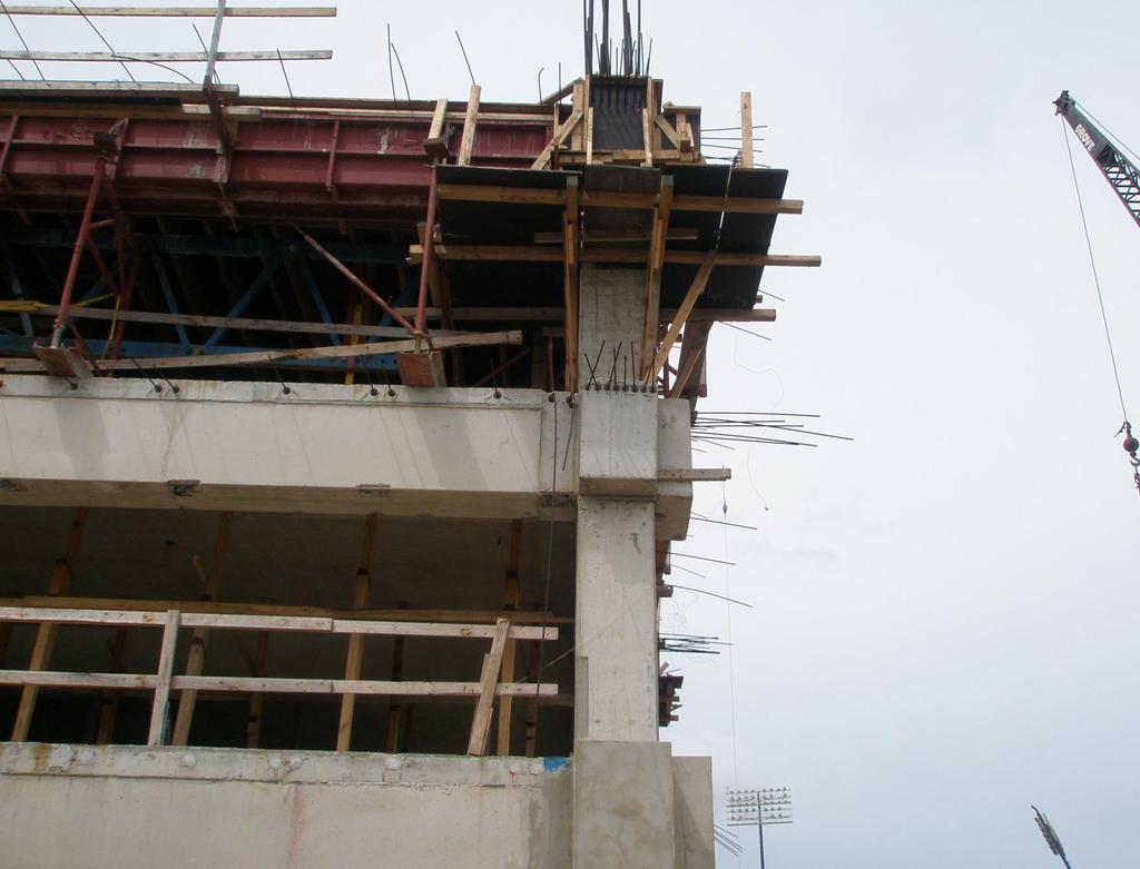
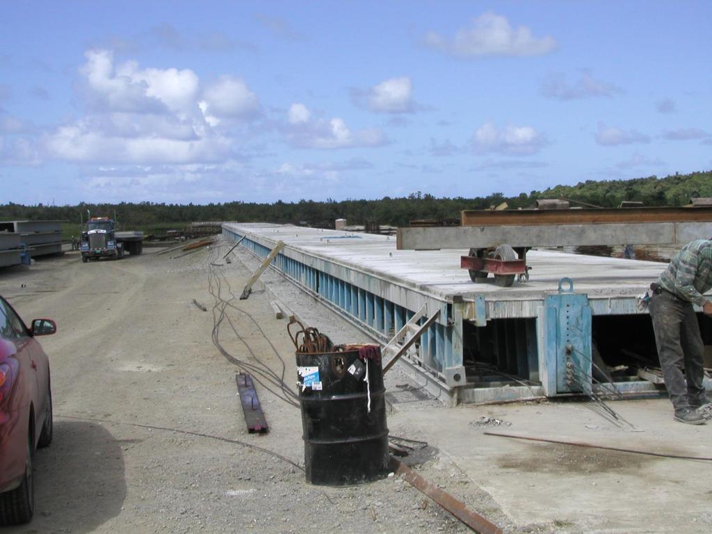
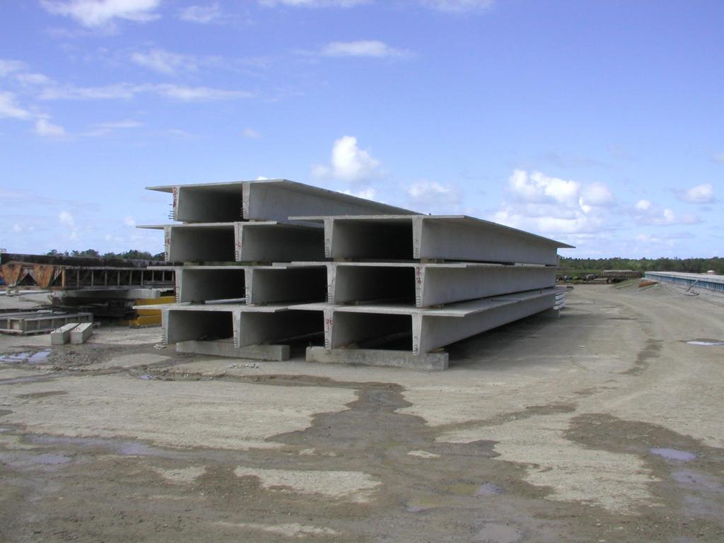
19 Pre-Stressing Construction Advantage 19


20 Pre-Stressing Construction Advantage 20
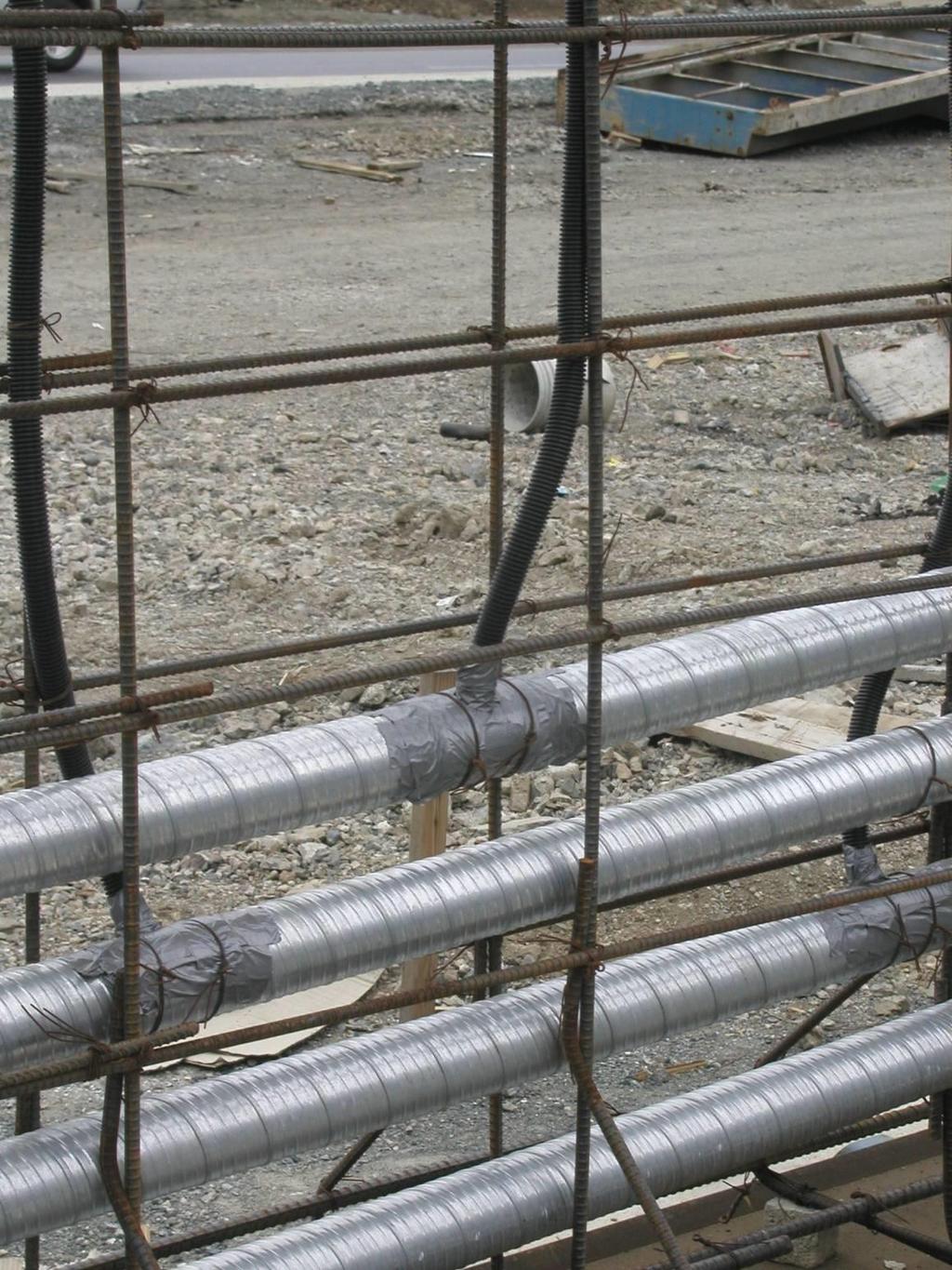
21 Pre-Stressing Element Connections 21
22 Pre-Stressing Element Connections
23 Pre-Stressing Element Connections 23


24 Pre-Stressed Slabs
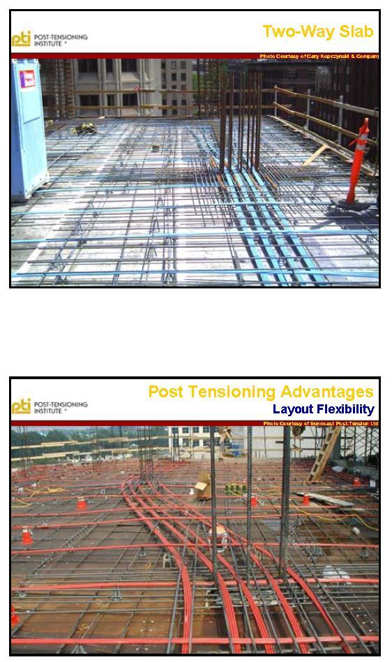

25 Pre-Stressed Slabs.
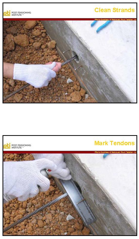
26 Pre-Stressed Slabs


27

28 Pre-Stressed Slabs


29 Pre-Stressed Slabs
30 Pre-Stressed Slabs

31 Pre-Stressed Slabs
32 Pre-Stressed Slabs
33 Pre-Stressed Slabs

34 Pre-Stressed Slabs
35 Pre-Stressed Slabs

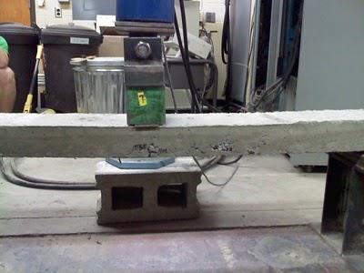
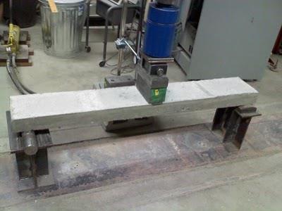
36 Pre-Stressed Beams

37 Pre-Stressed Beams
38 Pre-Stressed Beams

39 Pre-Stressed Beams

40 Pre-Stressed Beams
41 Pre-Stressed Beams

42 Pre-Stressed Beams

43 Pre-Stressed Columns

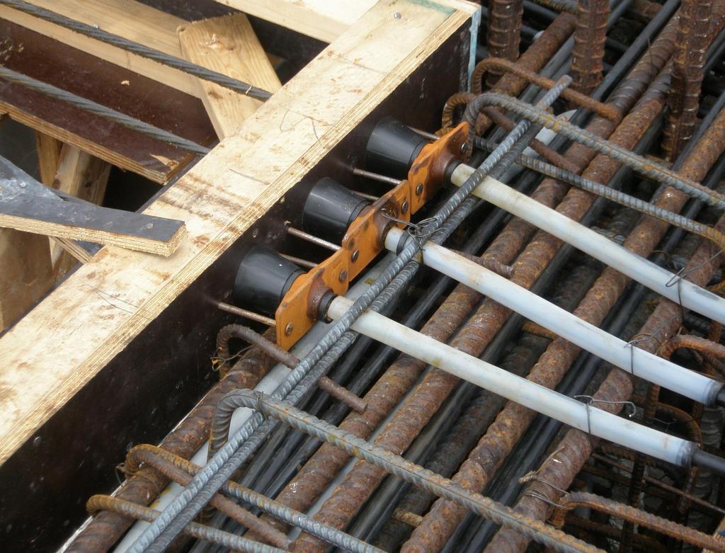
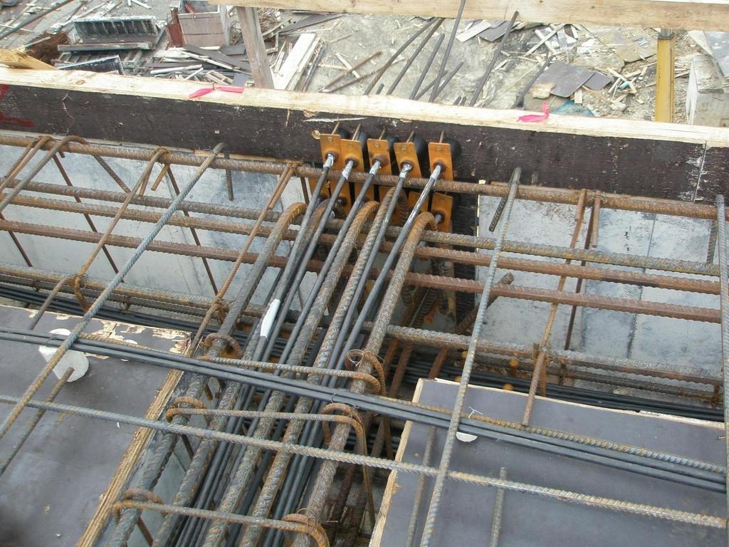
44 Post-Tensioned Beams

45 Post-Tensioned Beams

46 Post-Tensioned Beams

47 Post-Tensioned Beams

48 Post-Tensioned Beams

49 Post-Tensioned Beams
50 Post-Tensioned Beams

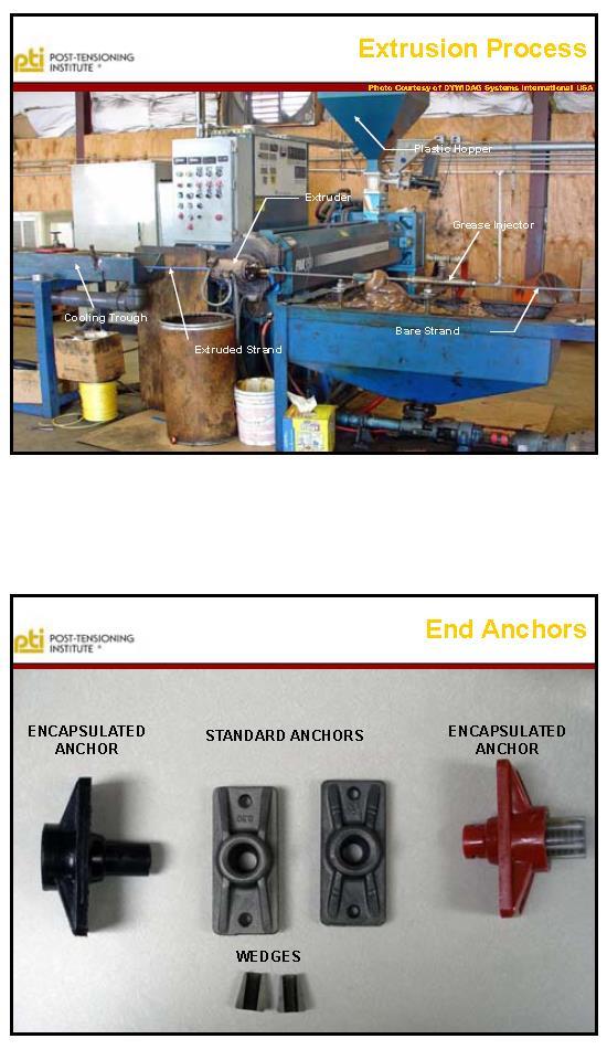
51 Post-Tensioned Anchorages


52 Post-Tensioned Anchorages
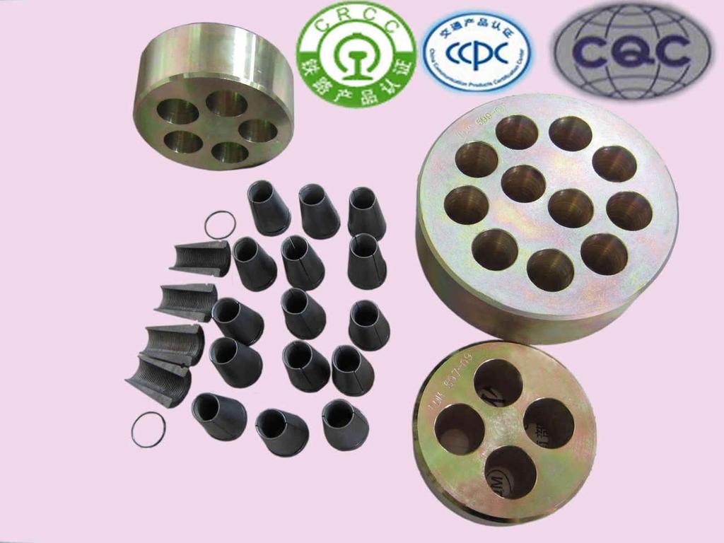
53 Post-Tensioned Anchorages


54 Post-Tensioned Bars

55 Pre-stressed Building Examples 55

56 Pre-stressed Building Examples 56
57 Centro de Transferencia de Tecnología en Transportación ABC: Vigas Pretensadas para Puentes Principios Básicos de Diseño Materials for Reinforced and Pre-stressed Concrete 1

58 Presentation- References 2
59 Compressive Strength of Concrete Compressive strength 6 12 ASTM C 31 ASTM C 39 3
60 Compressive Strength of Concrete Compressive strength Curve Stress f c E c = w c f c Strain 4
61 Compressive Strength of Concrete Compressive strength Curves 5
62 Tension Strength of Concrete Tensile strength Varies between 8% and 15% of the compressive strength 6
63 Tension Strength of Concrete Modulus of rupture (flexural test) b h f r = 6M bh 2 7
64 Tension Strength of Concrete Modulus of rupture (flexural test) ASTM C 78 Standard Test Method for Flexural Strength of Concrete (Using Simple Beam with Third-Point Loading) ASTM C 293 Standard Test Method for Flexural Strength of Concrete (Using Simple Beam With Center-Point Loading) 8
65 Tension Strength of Concrete Split cylinder test P d l 9
66 Tension Strength of Concrete Split cylinder test P d l f ct = 10 2P pld
67 Tension Strength of Concrete Split cylinder test ASTM C 496 Standard Test Method for Splitting Tensile Strength of Cylindrical Concrete Specimens 11
68 Tension and Compression Strength Relationship Relationship between compressive and tensile strengths Tensile strength increases with an increase in compressive strength Ratio of tensile strength to compressive strength decreases as the compression strength increases Tensile strength f c 12
69 Tension and Compression Strength Relationship Relationship between compressive and tensile strengths Mean f ct = 6.4f c For deflections (Eq. 9-10): f r = 7.5f c For strength (ACI ): f r = 6f c 13
70 Shrinkage, Creep and Thermal Expansion Shrinkage Creep Thermal expansion 14
71 Shrinkage Shrinkage Shortening of concrete during hardening and drying under constant temperature Moisture diffuses out of the concrete Exterior shrinks more than the interior Tensile stresses in the outer layer and compressive stresses in the interior 15
72 Shrinkage Shrinkage Shrinkage Strain Time 16
73 Shrinkage Shrinkage When not adequately controlled, can cause: Unsightly or harmful cracks Large and harmful stresses Partial loss of initial prestress Reinforcement restrains the development of shrinkage 17
74 Creep Creep Load removed Strain Load applied Creep strain Elastic recovery Creep recovery Elastic strain Permanent Deformation 18 Time
75 Creep Creep strains can lead to Increase in deflections with time Redistribution of stresses Decrease in pre-stressing forces 19
76 Thermal Expansion Thermal expansion Coefficient of thermal expansion or contraction Affected by: Composition of the concrete Moisture content of the concrete Age of the concrete 20
77 Thermal Expansion Thermal expansion Coefficient of thermal expansion or contraction Normal weight concrete Siliceous aggregate: 5 to 7 x 10⁻⁶ strain/f Limestone/calcareous aggregate: 3.5 to 7 x 10⁻⁶ strain/f Lightweight concrete 3.6 to 6.2 x 10⁻⁶ strain/f A value of 5.5 x 10⁻⁶ strain/f is satisfactory 21
78 Reinforcing Steels Deformed Bar Reinforcement Welded Wire Reinforcement Pre-stressing Steel 22
79 Deformed Bar Reinforcement ASTM A 615, Specification for Deformed and Plain Carbon-Steel Bars for Concrete Reinforcement ASTM A 706, Specification for Low-Alloy Steel Deformed and Plain Bars for Concrete Reinforcement ASTM A 996, Specification for Rail-Steel and Axle-Steel Deformed Bars for Concrete Reinforcement 23
80 Deformed Bar Reinforcement 24
81 Deformed Bar Reinforcement f s = E s e s f s = f y 25

82 Deformed Bar Reinforcement Bar Designation Area (in. 2 ) Weight (plf) Diameter (in.) No Minimum yield Ultimate strength Steel Grade No stress, f y (ksi) (ksi) No No No No No No No No No
83 Pre-stressing Steel Strands Seven-wire Three- and Four-wire Wire Bars Plain Deformed 27
84 Pre-stressing Steel ASTM A 416, Standard Specification for Steel Strand, Uncoated Seven-Wire for Prestressed Concrete ASTM A 421, Standard Specification for Uncoated Stress-Relieved Steel Wire for Prestressed Concrete ASTM A 722, Standard Specification for Uncoated High-Strength Steel Bars for Prestressing Concrete 28

85 Pre-stressed 7-wire strand

86
87 Prestressing Steel 7-Wire Strands, f pu = 270 ksi Nominal Diameter (in.) Area (in. 2 ) Weight (plf) 3/ / / / /
88 Prestressing Steel Design Aid in PCI Design Handbook, 6th Ed. 32
89 Prestressing Steel 33
90 Prestressing Steel 34
91 Losses in Pre-stressed Concrete 35

92 Pre-stressed Losses The fraction of the jacking force (Pj) that is eventually transferred to the concrete after releasing the temporary anchor or withdrawal of the hydraulic jack is the Pi. This force also keeps on decreasing with time due to time-dependent response of constituent materials; steel and concrete and reduced to a final value known as effective pre-stressing force, βpi.
93 Pre-stressed Losses
94 Topics Addressed Pre-stressed Losses Elastic Shortening Creep of Concrete Shrinkage of Concrete Steel Relaxation 38
95 Pre-stressed Losses Essentially, the reduction in the pre-stressing force can be grouped into two categories: Immediate elastic loss during the fabrication or construction process, including elastic shortening of the concrete, anchorage losses, and frictional losses. Time-dependent losses such as creep and shrinkage and those due to temperature effects and steel relaxation, all of which are determinable at the service-load limit state of stress in the pre-stressed concrete element. An exact determination of the magnitude of these losses, particularly the time-dependent ones, is not feasible, since they depend on a multiplicity of interrelated factors. Empirical methods of estimating
96 Pre-stressed Losses losses differ with the different codes of practice or recommendations, such as those of the Pre-stressed Concrete Institute, the ACI ASCE joint committee approach, the AASHTO lump-sum approach, the Comite Eurointernationale du Be ton (CEB), and the FIP (Federation Internationale de la Pre contrainte). The degree of rigor of these methods depends on the approach chosen and the accepted practice of record
97 NOTATION A ps = total area of pre-stressing steel e = eccentricity of center of gravity of pre-stressing steel with respect to center of gravity of concrete at the cross-section considered E c = modulus of elasticity of concrete at 28 days E ci = modulus of elasticity of concrete at time prestress is applied E s = modulus of elasticity of prestressing steel. Usually 28,500,000 psi f cds = stress in concrete at center of gravity of prestressing steel due to all superimposed permanent dead loads that are applied to the member after it has been pre-stressed f cir = net compressive stress in concrete at center of gravity of prestressing steel immediately after the pre-stress has been applied to the concrete. f cpa = average compressive stress in the concrete along the member length at the center of gravity of the pre-stressing steel immediately after the prestress has been applied to the concrete
98 NOTATION (Cont.) f g = stress in concrete at center of gravity of prestressing steel due to weight of structure at time prestress is applied f pi = stress in prestressing steel due to Ppi = Ppi/Aps f pu = specifi ed tensile strength of prestressing steel, psi I c = moment of inertia of gross concrete section at the cross-section considered M d = bending moment due to dead weight of member being prestressed and to any other permanent loads in place at time of prestressing M ds = bending moment due to all superimposed permanent dead loads that are applied to the member after it has been prestressed P pi = prestressing force in tendons at critical location on span after reduction for losses due to friction and seating loss at anchorages but before reduction for ES, CR, SH, and RE
99 For members with bonded tendons: ES = K es E s f cir /E ci (1) where K es = 1.0 for pre-tensioned members K es = 0.5 for post-tensioned members where tendons are tensioned in sequential order to the same tension. With other post-tensioning procedures, the value for Kes may vary from 0 to 0.5. f cir = K cir f cpi fg (2) Where: K cir = 1.0 for post-tensioned members K cir = 0.9 for pre-tensioned members For members with bonded tendons: ES = K es E s f cpa /E ci (1a) Elastic Shortening of Concrete (ES)
100 Creep Loss (CR) In general, this loss is a function of the stress in the concrete at the section being analyzed. In posttensioned, nonbonded members, the loss can be considered essentially uniform along the whole span. Hence, an average value of the concrete stress between the anchorage points can be used for calculating the creep in posttensioned members.
101 Creep of Concrete (CR) In general, this loss is a function of the stress in the concrete at the section being analyzed. In post-tensioned, non-bonded members, the loss can be considered essentially uniform along the whole span. Hence, an average value of the concrete stress between the anchorage points can be used for calculating the creep in post-tensioned members. For members with bonded tendons: CR = K cr E s * (f cir - f cds ) / E c (3) Where: K cr = 2.0 for pre-tensioned members K cr = 1.6 for post-tensioned members For members made of sand-lightweight concrete the foregoing values of Kcr should be reduced by 20 percent. For members with unbonded tendons: CR = K cr E s / E c * f cpa (3a)
102 Shrinkage of Concrete (SH) As with concrete creep, the magnitude of the shrinkage of concrete is affected by several factors. They include mixture proportions, type of aggregate, type of cement, curing time, time between the end of external curing and the application of pre-stressing, size of the member, and the environmental conditions. Size and shape of the member also affect shrinkage. Approximately 80% of shrinkage takes place in the first year of life of the structure. The average value of ultimate shrinkage strain in both moist-cured and steam-cured concrete is given in the ACI 209 R-92 Report. For post-tensioned members, the loss in pre-stressing due to elastic shortening and shrinkage is somewhat less since most of the elastic shortening and some shrinkage has already taken place before posttensioning.
103 Shrinkage of Concrete (SH) SH = K sh E s ( V/S) (100 - RH) (4) where K sh = 1.0 for pretensioned members K sh is taken from Table for post-tensioned members. TABLE 1
![Relaxation of Tendons (RE) RE = [Kre - J (SH + CR + ES)] C (5)](/docs-images/73/68347487/images/104-4.jpg "where the values of K re, J, and C are taken from Tables 2 and 3.")
104 Relaxation of Tendons (RE) RE = [Kre - J (SH + CR + ES)] C (5) where the values of K re, J, and C are taken from Tables 2 and 3. TABLE 2
105 Relaxation of Tendons (RE) TABLE 3
106 Relaxation of Tendons (RE)
107 Relaxation of Tendons (RE)
108 Annual Average Relative Humidity
109 AASHTO Lump-Sum Losses Approximated Methods for Losses Computations
110
111 Pre-stressed Losses 55
112 EXAMPLE For the simply supported double-tee shown below, estimate loss of prestress using the procedures as outlined earlier under Computation of Losses. Assume the unit is manufactured in Green Bay, WI.
113 EXAMPLE
114 EXAMPLE
115
116 EXAMPLE
117 EXAMPLE
118 EXAMPLE Table 2 Table 2 Table 3
119
120
121 1 PRE-STRESSED CONCRETE SEMINAR Centro de Transferencia de Tecnología en Transportación ABC: Vigas Pretensadas para Puentes Principios Básicos de Diseño Pre-stressed concrete Design Service Design
122 2 PRE-STRESSED CONCRETE SEMINAR Introduction to the Service Design Concepts Serviceability Limit State Design (SLS) is design of prestressed concrete member at the service load stage. The SLS design is related with the working stress design method because the allowable stress limit controls the design process. SLS design approach, control the selection of the geometrical dimension and the layout of the prestressing steel regardless if it is pre-tensioned or post-tensioned member. After the SLS design is satisfied then the other factor such as shear design, torsion design, ultimate strength design, control of deflection and cracking are satisfied. Different with reinforced concrete design, in prestressed concrete design several load stage must be checked such as when load transfer stage, service load stage and ultimate load stage.
123 3 Basic Assumptions in the Service Design Method There are three basic concepts may be applied to design the prestressed concrete member using, as follows: 1. The material is assumed as an elastic composite Material. 2. The compressive stress is carried by the concrete material and the tensile stress is carried by the prestressing steel. 3. Pre-stressed concrete section is assumed un-cracked due to service load
124 Loading Stages Pre-stressed concrete design must consider all the loading stages started from the initial pre-stressing force until the limit state of failure. For each loading stage the actual stress must be checked and compare with the allowable stress defined by the code. At the ultimate stage the flexural capacity must be compared with the ultimate bending moment or shear. For serviceability limit state design the two loading stages may governs the design, as follows : 1. Initial Loading, a loading stage where the prestressing force is transferred to the concrete without any external loading except the self weight of the structural member. 2. Final Service Loading, a loading stage where the prestressing force already reduced by several losses and full service load is applied. 4
125 Loading Stages Complete loading stages for Serviceability limit state design of prestressed concrete member are as follows : Initial Loading a. Initial Prestressing Force. b. Self Weight (DL) Final Service Loading a. Full Dead Load (SDL) + Effective Prestressing Force. b. Full Service Load (DL+SDL+LL) + Effective Prestressing Force. The loading stages for of prestressed concrete member at Ultimate limit state design are as follows : Full Ultimate Load ( DL + SDL + LL) Where: are combination Factors 5
126 1. The pre-stressing force is maximum because the losses has not yet occurred. 2. The acting external loading is minimum. 3. The concrete strength is minimum as the concrete is still young. 6 THE TRANSFER STAGE Initial Loading Stage The intial pre-stresing force P i is acting in the concrete element, after the Transfer stage occurs. The process of transferring the force acting in the hydraulic jack to the concrete element is called The transfer stage The external load acting at this stage is normally the self weight (DL) of the structural member. After the force acting in the hydraulic jack is transferred, the concrete element is under one of several critical conditions for the reasons described as it follow follows :
127 7 Service Loading Stage Service load stage is a loading stage where the pre-stress long term loss already taken. The pre-stress long term loss already taken is the creep loss, shrinkage loss and steel relaxation loss. The external loading at this stage is the full service load these are self weight (DL), superimposed dead load (SDL) and live load (LL). This stage is critical because of as follows : 1. The pre stressing force is minimum because all the losses already taken. 2. The applied loading is maximum because all the service loads already applied. 3.The pre stressing force at this loading stage is designated as Pe.
 y t x M xz M xz =Bending Moment + s x")
 ( + ) M ( ) y I t Sad Beam is (-) Happy Beam is (+)")
128 (-) e 0 PRE-STRESSED CONCRETE SEMINAR Stresses and Moments Sign Convention y (+) y t x M xz M xz =Bending Moment + s x M xz (+) e 0 s top ( + ) ( + ) M ( + ) y I (-) y b t - s x s bot ( ) ( + ) M ( ) y I t Sad Beam is (-) Happy Beam is (+) 8
129 Stresses in Beams P Stresses Sign Convention M xz (+)s x-top (+)s x-top x N Axial Load in Beams N (+)s xa () s x-bottom (+) s xa x M xz Combined Bending and Axial Loading N N P s top = (+) s x-top + (+) s xa x s bottom = () s x-bottom + (+) s xa 9
130 What s Look Different???? There is nothing new, however to be consistent with many authors, now Compression stresses are positive and tension stresses are negative M xz =Bending Moment + s x M xz M xz - s x
131 11 PRE-STRESSED CONCRETE SEMINAR Stress Diagram The following figure shows the stress diagram for each loading stage, as follows : Initial Service Pre-Stress Self -Weight Losses Sup- Imp + Live Load
132 s s i i Loading- Stresses Initial Loading Stress Expression top bot Pi A Pi A + P (e i P (e i 0 I 0 I )y )y Final Service Loading - Stress Expression P (e )y M y t b + M s Pe 0 t DL t SDL t LL t s e top s A I I I I cs s P P (e )y M y M y M y e 0 b DL b SDL b LL b s e bot + s A I I I I ts σ ci = Initial concrete compressive stress (transfer stage) σ ti = Initial concrete tensile stress ( (transfer stage) σ cs = Service concrete compressive stress (service load stage) σ ts = Service concrete tensile stress (service load stage) M DL = Moment due to the beam self weight M SDL = Moment due to superimposed dead load M LL = Moment due to acting live load 12 M M DL I DL I y y y t b s s M ti ci y
133 σ all ci σ all ti σ all cs σ all ts The Max eccentricity limit so that no tensile stress will develop any where in the member could be found by setting σ = 0 ; N ( Ne) y 0 + A I or: 1 ( e) y (1 + A e t k t ) 0 2 r ( ) or: ; M min M S b y b ; e k ( + ) b b S b y t (+) y t (-) y b ALLOWABLE SERVICE STRESSES DENOMINATION = concrete compressive stress (transfer stage) = concrete tensile stress (transfer stage) = concrete compressive stress (service load stage) = concrete tensile stress (service load stage) DL ; M max Kern Center Concepts M DL + M SDL + M LL ; P i F i ; P e F e (-) k x t (+) k F i b 13

134 14 PRE-STRESSED CONCRETE SEMINAR Central Kern Central kern is a region which is an axial compressive force of any magnitude will not produce any tension at this section. The central kern is depends to the cross section. The central kern is independent to the applied compressive force and allowable stress.
135 s s s s s s i i top bot top bot PRE-STRESSED CONCRETE SEMINAR Basic Concepts Final Service Loading - Stress Expression Pe A Pe A Initial Loading Stress Expression P + i A P i A P P + e e (e I (e 0 0 I P i P i )y )y t b (e (e + 0 I 0 I M M ) ) DL I DL I y y t b y + t y b M + M SDL I SDL I M M y y t b DL I DL + I y y M M t b LL I LL I y y t b s ti s s s ci cs ts Geometry Related Code Related Geometry Limits
136 Pre-stressed Equations to Remember Initial Loading Stress Expression s s i i top bot Pi A Pi A + P (e i P (e i 0 I 0 I )y )y t b + M M DL I DL I y y t b s s ti ci Pi [1 A Pi [1 + A e ( k 0 b )] + e 0 ( ( )k t M S DL t )] M S DL t s ti Allow Be Careful!!!!! s ci Allow 16
137 Sign Convention Summary The sign convention for bending moment is as follows : 1. Plus sign (+) is used to for positive bending moment which is compression in the top fiber and tension in the bottom fiber. 2. Minus sign (-) is used to for negative bending moment which is tension in the top fiber and compression in the bottom fiber. The sign convention for bending moment due to pre-stressing eccentricity is as follows : 1. The bending moment is positive (+) if the eccentricity goes up ward / above the neutral axis. 2. The bending moment is negative (-) if the eccentricity goes down ward / below the neutral axis. The sign convention for pre stressing force is as follows : 1. The pre-stressing force is always in plus (+) sign. The sign convention for pre-stressing eccentricity is as follows : 1. The eccentricity is positive (+) if goes down ward / below the neutral axis. 2. The eccentricity is negative (-) if goes up ward / above the neutral axis. The sign convention for concrete stress is as follows : 1. Plus sign (+) is used to for compressive concrete stress. 2. Minus sign (-) is used for tensile concrete stress.
138 i s top i s bot s s s s s s s s top top bot bot P i i I t b Loading Stages - Stresses Initial Loading Stress Expression P i A i + A P( e ) y 0 I P( e ) y 0 + M M DL I DL I y y t b s s ti ci P e i [1 ( A k P P (e )y M y M y M y e 0 DL SDL LL e t + t + t + t s A I I I I P e M M M e 0 DL SDL LL s [1 ( )] s cs A k St St St b P P (e )y M y M y M y e e 0 b DL b SDL b LL b + A I I I I P e M M M e 0 DL SDL LL s [1 + ( )] ts A ( )k Sb Sb Sb Allow Allow t Using the the previous equations will be re-writted 18 as: P i [1 + A b )] + e ) k t M S DL t )] Final Service Loading - Stress Expression ( ( 0 0 M S DL t s ti s cs Allow s cs ts s ci ts Allow
139 s s s s i i s s top bot top bot s s ci cs ts Loading Stages - Stresses Initial Loading Stress Expression F e M s i 0 min [1 ( )] + s ti A k S ti t s Fi A A A [1 + F F i i [1 [1 + b e 0 ( ( )k e ( k 0 b t e 0 ( ( )k )] )] + t M max S t M )] M min S t max S b s Allow Final Service Loading - Stress Expression s cs s ci Allow ts Allow Allow 19
140 e e 0 0 k k b t Loading Stages- Exentricity Initial Loading Excentricity 1 + ( Fi 1 + ( Fi ) (M ) (M min min + s s ti ci Allow Allow S S Final Service Loading - Excentricity Expression 1 e k ( ) (M s Allow 0 b + S ) F max cs t i e 0 k t + ( 1 Fi ) (M max + s ts Allow t b S ) ) b ) 20
141 Loading Stages- Forces Initial Loading Force Expression Fi Fi (M (M min min + s s ti ci Allow Allow S t S ) / ) / b (e 0 (e 0 k b k ) t ) Final Service Loading - Force Expression Fi Fi (M (M max max + s s cs ts Allow Allow S S t b ) / )/ (e (e 0 0 k k b t ) ) 21
142 Loading Stages - Forces Initial Loading Force Expression 1 Allow (e k ) /(M s 0 b S ) F min ti t i 1 Allow (e0 k t ) /(M s + S ) F min ci b i Final Service Loading - Force Expression 1 Allow (e0 k ) /(M s b S ) F max cs t i 1 Fi (e 0 k t ) / (M max + s ts Allow S b ) 22
143 23 Service Condition Allowable Stresses As explained before that pre-stressed concrete design in the serviceability limit state is controlled by the allowable stress determined by the code. The allowable stress is both for allowable stress in concrete and allowable stress in pre-stressing steel. There are at least four stress limitations, as follows : 1. Tensile stress and compressive stress at transfer stage. 2. Tensile stress and compressive stress at service load stage.
 f c = allowable concrete compressive stress (service load stage) f t = allowable concrete tensile stress (service load stage) f ci = initial concrete compressive")
144 Service Condition Allowable Stresses Allowable concrete stresses for transfer stage and service load stage f ci = allowable concrete compressive stress (transfer stage) f ti = allowable concrete tensile stress (transfer stage) f c = allowable concrete compressive stress (service load stage) f t = allowable concrete tensile stress (service load stage) f ci = initial concrete compressive strength f c = 28 days concrete compressive strength 24

145 25 Service Condition Allowable Stresses Allowable steel stresses for transfer stage and service load stage
146 Design of Flexural Members The design process is more difficult than analysis process because the unknown variables are more than when the section is analyzed. In the design process When need to find the minimum section to satisfy the allowable stress. After the section is determined then the actual stress also must be checked. Two governs condition are the maximum prestressing force with minimum external load and minimum pre-stressing force with maximum external load. ECCENTRIC PRESTRESSING The figure below shows the stress history of the eccentric pre-stressing system. Two stress conditions are used to determine the minimum section modulus. For eccentric pre-stressing the minimum section is controlled by maximum eccentricity at mid span. 26
147 Stress History
148 Stress History The followings are the explanation of the stress history, as follows : The actual stress due to pre-stressing and external load is shown with dashed line. Due to initial pre-stressing the stress will be tension in the top fiber (must be less than allowable tensile stress fti ) and compression in the bottom fiber (must be less than allowable compressive stress fci ).Due to effective pre-stressing the stress will be compression in the top fiber (must be less than allowable compressive stress fc ) and tension in the bottom fiber (must be less than allowable tensile stress ft ).The top fiber is controlled by the initial allowable tensile stress fti and allowable compressive stress fc. The bottom fiber is controlled by the initial allowable compressive stress fci and allowable tensile stress f 28 t.
149 Stress History 29
150 As previously explained the top fiber is controlled by the initial allowable tensile stress f ti and allowable compressive stress fc. So the section modulus for the top fiber St will be derived based on the two allowable stresses above. s s s i top top Initial Loading Stress Expression s s cs ti P i A Stress History A [1 F i [1 e ( k 0 b e ( k )] + M S min t M max S t s Final Service Loading - Stress Expression ti 0 )] + cs b s Allow Allow 30
151 but: PRE-STRESSED CONCRETE SEMINAR Assuming that all pre-stressed losses have occurred leads to a loading for which: F e M i 0 [1 ( )] + min s1 A k S b t Which can also be written as : F e M M M [ i [1 ( )] min] 0 + min min s1 A k S S S b t t t P M i e 0 min ] Allow [1 ( )] + s A k S ti t [ Therefore: s ti Allow + b M S min t (1 ) Stress History s 1 31
152 Stress History Now if we add a moment of amplitude ΔM to the section the corresponding additional stress on the top fiber will be : M s top St And the resulting stress due to the initial stress at the top plus the additional stress due to the moment ΔM must be less than or equal to the allowable compressive stress s s 1 + scs top Using previous equations it results that : s ti Allow + M min S t (1 ) + M S t Allow s CS Allow 32
153 The previous equation can be expressed as: S t Preliminary Sizing M (1 ) + M min s Allow Allow cs s ti By similarly examining the state of stress on the bottom fibber, it can be shown that: Note that: S b M (1 ) + M min s Allow s Allow ci ts M max M min + M 33
154 34
155 35
156 36
157 Pre-stressed Equations to Remember Initial Loading Stress Expression s s i i top bot Pi A Pi A + P (e i P (e i 0 I 0 I )y )y t b + M M DL I DL I y y t b s s ti ci Pi [1 A Pi [1 + A e ( k 0 b )] + e 0 ( ( )k t M S DL t )] M S DL t s ti Allow Be Careful!!!!! s ci Allow 37
158 s s s s s s s s top top bot bot PRE-STRESSED CONCRETE SEMINAR cs ts 0 0 Pre-stressed Equations to Remember Final Service Loading - Stress Expression Pe A s Pe A s + P P e Pe e Pe A (e A I (e I )y t [1 )y b [1 + + e ( k M 0 b M DL I DL I e 0 ( ( )k t y )] + y t b + M S )] DL t M M M S SDL + SDL DL b I I y M t S y SDL b t + M S SDL b M + M LL I M S LL I y t LL t M S LL b 38 s s cs cs ts Allow Be Careful!!!!! y b s s ts Allow
159 Pre-Stressed Design The Procedure The pre-stressed concrete design start by suggesting cross sections that could be solution to the problem. Having these sections the next step will be to determine the required pre-stressing force and its eccentricity at the critical section. After the pre-stressing force is determined this pre-stressing force is used along the span and we must compute the eccentricity at other location so there is no allowable stress is exceeded. The common method is by computing the eccentricity envelope which is the maximum location that produces concrete stress less than allowable value. The spreadsheet that accompany this presentation will be used to clarify the whole concepts. 39

160 Pre-Stressed Concrete Design - Example This example was taken from the Pre-stresses concrete Design Book by Antoine Naaman. In the example the author has used Z for the section modulus insteadof the typical mechanic of materials Books that normally use S.
161 Pre-Stressed Concrete Design - Example
162 Pre-Stressed Concrete Design - Example
163 Pre-Stressed Concrete Design - Example
164 Pre-Stressed Concrete Design - Example

165 Pre-Stressed Concrete Design - Example

166 Pre-Stressed Concrete Design - Example
167 Centro de Transferencia de Tecnología en Transportación ABC: Vigas Pretensadas para Puentes Principios Básicos de Diseño Ultimate Flexural Design Capacity 1
168 Load Combinations U = 1.4 (D + F) U = 1.2 (D + F + T) (L + H) (L r or S or R) U = 1.2D (L r or S or R) + (1.0L or 0.8W) U = 1.2D + 1.6W + 1.0L + 0.5(L r or S or R) U = 1.2D + 1.0E + 1.0L + 0.2S U= 0.9D + 1.6W + 1.6H U= 0.9D + 1.0E + 1.6H
169 Strength Design Strength design is based using the rectangular stress block The stress in the pre-stressing steel at nominal strength, f ps, can be determined by strain compatibility or by an approximate empirical equation For elements with compression reinforcement, the nominal strength can be calculated by assuming that the compression reinforcement yields. Then verified. The designer will normally choose a section and reinforcement and then determine if it meets the basic design strength requirement: M n M u
170 Stress Block Theory The Whitney stress block is a simplified stress distribution that shares the same centroid and total force as the real stress distribution =
171 Equivalent Stress Block b 1 Definition b 1 = 0.85 when f c < = 4,000 psi b 1 = {f c (ksi) 4(ksi)} b 1 =.65 when f c > 8,000 psi
172 Strength Design Flowchart
173 Find depth of compression block 1
174 Depth of Compression Block a A s f y A ' s f ' y.85 f ' c b Where: A s is the area of tension steel A s is the area of compression steel f y is the mild steel yield strength Assumes compression steel yields

175 Flanged Sections 2 Checked to verify that the compression block is truly rectangular
176 Compression Block Area If compression block is rectangular, the flanged section can be designed as a rectangular beam = = A comp a b

 h f to find a A w a A w b")
177 Compression Block Area If the compression block is not rectangular (a> h f ), = A f (b b w ) h f to find a A w a A w b w A comp A f
178 Determine Neutral Axis From statics and strain compatibility c a / b

179 3 PRE-STRESSED CONCRETE SEMINAR Check Compression Steel c 3 d' Verify that compression steel has reached yield using strain compatibility
180 Compression Comments By strain compatibility, compression steel yields if: c 3 d' If compression steel has not yielded, calculation for a must be revised by substituting actual stress for yield stress Non prestressed members should always be tension controlled, therefore c / d t < Add compression reinforcement to create tesnion controlled secions


181 4 Moment Capacity 2 equations rectangular stress block in the flange section rectangular stress block in flange and stem section
182 Strength Design Flowchart
183 Stress in Strand f se - stress in the strand after losses f pu - is the ultimate strength of the strand f ps - stress in the strand at nominal strength r p (A ps )/( bd p ) Pre-stressed Reinforcement This portion of the flowchart is dedicated to determining the stress in the prestress reinforcement 1
184 Stress in Strand Typically the jacking force is 65% or greater The short term losses at midspan are about 10% or less The long term losses at midspan are about 20% or less f se 0.5 f pu
185 Stress in Strand f pu - is the ultimate strength of the strand f ps - stress in the strand at nominal strength w (A s *f y )/( bdf c ) Non Pre-stressed Reinforcement w (A s *f y )/( bdf c ) Non Pre-stressed Reinforcement r p (A ps )/( bd p ) This portion of the flowchart is dedicated to determining the stress in the prestress reinforcement 5 Pre-stressed Reinforcement
186 Stress in Strand Prestressed Bonded reinforcement f ps f pu 1 g p b 1 r p f pu f ' c d d p ( w w ' g p = factor for type of prestressing strand, see ACI 18.0 =.55 for f py /f pu not less than.80 =.45 for f py /f pu not less than.85 =.28 for f py /f pu not less than.90 (Low Relaxation Strand) r p = prestressing reinforcement ratio
187 Compression Block Height Assumes compression steel yields a A ps f ps A s f y A ' s f ' y.85 f ' c b Prestress component Where A ps - area of prestressing steel f ps - prestressing steel strength
188 Flexural Strength Reduction Factor See figure next Page
189 Flexural Strength Reduction Factor Based on primary reinforcement strain Strain is an indication of failure mechanism Three Regions c/d t = > 0.6 = 0.70 with spiral ties = 0.65 with stirrups c/d t <= = 0.90 with spiral ties or stirrups
190 Transition Zone < e < at extreme steel tension fiber, or < c/d t < 0.6 = (e) or = (e) with spiral ties = /(c/d t ) or = /(c/d t ) with stirrups
191 Strand Slip Regions ACI Section where the strand embedment length is less than the development length =0.75
192 Limits of Reinforcement To prevent failure immediately upon cracking, Minimum A s is determined by: A s,min 3 f y f ' c b w d 200 b w d f y A s,min is allowed to be waived if tensile reinforcement is 1/3 greater than required by analysis
193 Limits of Reinforcement The flexural member must also have adequate reinforcement to resist the cracking moment Where M n 1.2M cr M cr S bc P A Pe f S r b M nc S bc 1 S b Section after composite has been applied, including prestress forces Correction for initial stresses on noncomposite, prior to topping placement
194 Critical Sections
195 Example from PCA 29
196 Example from PCA 30
197 Example from PCA 31
Flexure Design Sequence
 Prestressed Concrete Beam Design Workshop Load and Resistance Factor Design Flexure Design Flexure Design Sequence Determine Effective flange width Determine maximum tensile beam stresses (without prestress)
PRESTRESSED CONCRETE STRUCTURES. Amlan K. Sengupta, PhD PE Department of Civil Engineering, Indian Institute of Technology Madras
 PRESTRESSED CONCRETE STRUCTURES Amlan K. Sengupta, PhD PE Department of Civil Engineering, Indian Institute of Technology Madras Module 2: Losses in Prestress Lecture 10: Creep, Shrinkage and Relaxation
ST7008 PRESTRESSED CONCRETE
 ST7008 PRESTRESSED CONCRETE QUESTION BANK UNIT-I PRINCIPLES OF PRESTRESSING PART-A 1. Define modular ratio. 2. What is meant by creep coefficient? 3. Is the deflection control essential? Discuss. 4. Give
ADAPT PT7 TUTORIAL FOR BEAM FRAME 1
 ADAPT PT7 TUTORIAL FOR BEAM FRAME 1 Technical Note Structural Concrete Software System TN189_PT7_tutorial_beam_frame 012705 1 BEAM FRAME The objective of this tutorial is to demonstrate the step-by-step
ADAPT PT7 TUTORIAL FOR ONE-WAY SLAB 1
 Structural Concrete Software System TN187_PT7_tutorial_one_way_slab 012705 ADAPT PT7 TUTORIAL FOR ONE-WAY SLAB 1 1. ONE-WAY SLAB SUPPORTED ON BEAMS The objective of this tutorial is to demonstrate the
Chapter 2 Notation and Terminology
 Reorganized 318 Chapter Titles Chapter 1 General 1.1 Scope 1.2 Purpose 1.3 Interpretation 1.4 Drawings and Specifications 1.5 Testing and Inspection 1.6 Administatration and Enforcement 1.6.1 Retention
Part I: Introduction. Prestressed Concrete Bridge Design Basic Principles. Praveen Chompreda, Ph. D. Recall that in Reinforced Concrete
 Prestressed Concrete Bridge Design Basic Principles Emphasizing AASHTO LRFD Procedures Praveen Chompreda, Ph. D. EGCE 406 Bridge Design MAHIDOL UNIVERSITY 2010 Part I: Introduction Reinforced vs. Prestressed
Appendix M 2010 AASHTO Bridge Committee Agenda Item
 Appendix M 2010 AASHTO Bridge Committee Agenda Item 2010 AASHTO BRIDGE COMMITTEE AGENDA ITEM: SUBJECT: LRFD Bridge Design Specifications: Section 5, High-Strength Steel Reinforcement TECHNICAL COMMITTEE:
ADAPT-PT 2010 Tutorial Idealization of Design Strip in ADAPT-PT
 ADAPT-PT 2010 Tutorial Idealization of Design Strip in ADAPT-PT Update: April 2010 Copyright ADAPT Corporation all rights reserved ADAPT-PT 2010-Tutorial- 1 Main Toolbar Menu Bar View Toolbar Structure
TABLE OF CONTENTS DESIGN EXAMPLES NOTATION 9.0 INTRODUCTION
 PCI BRIDGE DESIGN MANUAL CHAPTER 9 NOTATION TABLE OF CONTENTS DESIGN EXAMPLES 9.0 INTRODUCTION 9.1 DESIGN EXAMPLE - AASHTO BOX BEAM, BIII-48, SINGLE SPAN WITH NON-COMPOSITE WEARING SURFACE. DESIGNED IN
ADAPT-PTRC 2016 Getting Started Tutorial ADAPT-PT mode
 ADAPT-PTRC 2016 Getting Started Tutorial ADAPT-PT mode Update: August 2016 Copyright ADAPT Corporation all rights reserved ADAPT-PT/RC 2016-Tutorial- 1 This ADAPT-PTRC 2016 Getting Started Tutorial is
Reinforced Concrete Design. Lecture no. 1
 Reinforced Concrete Design Lecture no. 1 Mechanics of RC Concrete is strong in compression but week in tension. Therefore, steel bars in RC members resist the tension forces. RC Members Reinforced concrete
Structural Option April 7 th, 2010
 Gravity System (Depth Topic I) Post Tensioned Slab A new floor system was designed in an attempt to create a more consistent flooring system throughout the entire building. This new design consists of
GATE SOLVED PAPER - CE
 YEAR 2013 Q. 1 Maximum possible value of compaction factor for fresh (green) concrete is (A) 0.5 (B) 1.0 (C) 1.5 (D) 2.0 Q. 2 As per IS 456 : 2000, bond strength of concrete t bd = 12. for M20. It is increased
PRESTRESSED CONCRETE STRUCTURES. Amlan K. Sengupta, PhD PE Department of Civil Engineering Indian Institute of Technology Madras
 PRESTRESSED CONCRETE STRUCTURES Amlan K. Sengupta, PhD PE Department of Civil Engineering Indian Institute of Technology Madras Module - 4: Design of Members Lecture - 17: Design of Members for Axial Tension
The use of 0.5 and 0.6 in. (13 and 15 mm) diameter
 diameter") Benefits of using.7 in. (18 mm) diameter strands in precast, pretensioned girders: A parametric investigation Jessica Salazar, Hossein Yousefpour, Alex Katz, Roya Alirezaei Abyaneh, Hyun su Kim, David
Benefits of using.7 in. (18 mm) diameter strands in precast, pretensioned girders: A parametric investigation Jessica Salazar, Hossein Yousefpour, Alex Katz, Roya Alirezaei Abyaneh, Hyun su Kim, David
CHAPTER 11: PRESTRESSED CONCRETE
 CHAPTER 11: PRESTRESSED CONCRETE 11.1 GENERAL (1) This chapter gives general guidelines required for the design of prestressed concrete structures or members with CFRM tendons or CFRM tendons in conjunction
HIGH PERFORMANCE CONCRETE. by John J. Roller CTLGroup
 HIGH PERFORMANCE CONCRETE by John J. Roller CTLGroup Early Louisiana HPC Research Law & Rasoulian (1980) Adelman & Cousins (1990) Bruce, Russell & Roller (1990-1993) Law & Rasoulian (1980) Concrete strengths
CHAPTER 2. Design Formulae for Bending
 CHAPTER 2 Design Formulae for Bending Learning Objectives Appreciate the stress-strain properties of concrete and steel for R.C. design Appreciate the derivation of the design formulae for bending Apply
Long-term Stress of Simply Supported Steel-concrete Composite Beams
 The Open Construction and Building Technology Journal, 2011, 5, 1-7 1 Open Access Long-term Stress of Simply Supported Steel-concrete Composite Beams Min Ding 1,2, Xiugen Jiang 1, Zichen Lin 3 and Jinsan
The Hashemite University Department of Civil Engineering. Dr. Hazim Dwairi 1
 Department of Civil Engineering Lecture 8 Deflection and Camber Introduction Prestressed concrete beams are more slender than R.C. beams, high span/depth ratios; thus, more deflection. Camber may be important.
1 Prepared By:Mr.A.Sathiyamoorthy, M.E., AP/Civil
 UNIVERSITY QUESTIONS PART A UNIT 1: INTRODUCTION THEORY AND BEHAVIOUR 1. List the loss of prestress. 2. Define axial prestressing. 3. What is the need for the use of high strength concrete and tensile
ASSIGNMENT 1 ANALYSIS OF PRESTRESS AND BENDING STRESS BFS 40303
 Instruction : Answer all question ASSIGNMENT 1 ANALYSIS OF PRESTRESS AND BENDING STRESS BFS 40303 1. A rectangular concrete beam, 100 mm wide by 250 mm deep, spanning over 8 m is prestressed by a straight
Flexure and Serviceability Limit State
 UNIT 3 Flexure and Serviceability Limit State Beam A structural member that support transverse (Perpendicular to the axis of the member) load is called a beam. Beams are subjected to bending moment and
One-Way Wide Module Joist Concrete Floor Design
 One-Way Wide Module Joist Concrete Floor Design A 1 3 4 30'-0" 30'-0" 30'-0" 3' B 3' C 3' D 3' E 4" 4" (typ.) 3' F 0" 0" (typ.) Figure 1 One-Way Wide Module Joist Concrete Floor Framing System 1 Overview
Continuous Beam Design with Moment Redistribution (ACI )
") Continuous Beam Design with Moment Redistribution (ACI 318-14) Continuous Beam Design with Moment Redistribution (ACI 318-14) A structural reinforced concrete continuous beam at an intermediate floor level
Continuous Beam Design with Moment Redistribution (ACI 318-14) Continuous Beam Design with Moment Redistribution (ACI 318-14) A structural reinforced concrete continuous beam at an intermediate floor level
Contents. Foreword 1 Introduction 1
 Contents Notation x Foreword xiii 1 Introduction 1 1.1 Aims of the Manual 1 1.2 Eurocode system 1 1.3 Scope of the Manual 3 1.4 Contents of the Manual 4 1.5 Notation and terminology 4 2 General principles
BS EN :2004 EN :2004 (E)
") Contents List 1. General 1.1 Scope 1.1.1 Scope of Eurocode 2 1.1.2 Scope of Part 1-1 of Eurocode 2 1.2 Normative references 1.2.1 General reference standards 1.2.2 Other reference standards 1.3 Assumptions
Contents List 1. General 1.1 Scope 1.1.1 Scope of Eurocode 2 1.1.2 Scope of Part 1-1 of Eurocode 2 1.2 Normative references 1.2.1 General reference standards 1.2.2 Other reference standards 1.3 Assumptions
14. Structural Concrete
 14. Structural Concrete 14.1. Materials 14.2. Reinforcement 14.3. Structural Concrete Design 14.4. Prestressed Concrete Girders Section 5 of the LRFD Specifications presents unified design requirements
ADAPT PT7 TUTORIAL FOR A NON-PRISMATIC SLAB 1
 Structural Concrete Software System ADAPT PT7 TUTORIAL FOR A NON-PRISMATIC SLAB 1 TN190_PT7_non_prismatic_slab 012705 1. NON-PRISMATIC (SEGMENTAL) COLUMN-SUPPORTED SLAB The objective of this tutorial is
IMPLEMENTATION OF DEFLECTION WITH ALLOWANCE FOR FLEXURAL CRACKING IN ADAPT-PT
 Your Partner in Structural Concrete Design TN310_PT8_cracked_deflection_3 082508 IMPLEMENTATION OF DEFLECTION WITH ALLOWANCE FOR FLEXURAL CRACKING IN ADAPT-PT This Technical Note details the implementation
Post-tensioned prestressed concrete bridge - assignment
 Post-tensioned prestressed concrete bridge - assignment Design a post-tensioned prestressed concrete bridge of a three-span arrangement. The construction is prestressed at the age of 7 days and put into
Reinforced Concrete Design. A Fundamental Approach - Fifth Edition
 CHAPTER REINFORCED CONCRETE Reinforced Concrete Design A Fundamental Approach - Fifth Edition Fifth Edition REINFORCED CONCRETE A. J. Clark School of Engineering Department of Civil and Environmental Engineering
ADAPT-PT 2010 GETTING STARTED GUIDE
 ADAPT-PT 2010 GETTING STARTED GUIDE Copyright ADAPT 2007, 2008 all rights reserved support@adaptsoft.com www.adaptsoft.com ADAPT Corporation, Redwood City, California, USA, Tel: +1 (650) 306-2400 ADAPT
DESIGN OF POST-TENSIONED MEMBERS IN BENDING USING ACI SIMPLIFIED PROCEDURE
 Structural Concrete Software System TN 179 Aci_simplified_M_design3 011005 DESIGN OF POST-TENSIONED MEMBERS IN BENDING USING ACI 318 2002 SIMPLIFIED PROCEDURE 1. BACKGROUND 1.1 GENERAL The following describes
Continuous Beam Design with Moment Redistribution (CSA A )
") Continuous Beam Design with Moment Redistribution (CSA A23.3-14) Continuous Beam Design with Moment Redistribution (CSA A23.3-14) A structural reinforced concrete continuous beam at an intermediate floor
Continuous Beam Design with Moment Redistribution (CSA A23.3-14) Continuous Beam Design with Moment Redistribution (CSA A23.3-14) A structural reinforced concrete continuous beam at an intermediate floor
Fundamentals of Post Tensioned Concrete Design for Buildings
 Fundamentals of Post Tensioned Concrete Design for Buildings Part Three by John P. Miller Overview of This Course This is Part Two of a two-part course that covers the fundamentals of post-tensioned concrete
PROFESSIONAL DEVELOPMENT SERIES
 Post-Tensioning for Two-Way Flat Plate Construction By Amy Reineke Trygestad, P.E. PROFESSIONAL DEVELOPMENT SERIES October 2005 Professional Development Series Every major metropolitan area is getting
Reinforced Concrete Column Design
 Reinforced Concrete Column Design Compressive Strength of Concrete f cr is the average cylinder strength f c compressive strength for design f c ~2500 psi - 18,000 psi, typically 3000-6000 psi E c estimated
PRESTRESSED CONCRETE STRUCTURES UNIT I INTRODUCTION THEORY AND BEHAVIOUR
 BASIC CONCEPTS: PRESTRESSED CONCRETE STRUCTURES UNIT I INTRODUCTION THEORY AND BEHAVIOUR A prestressed concrete structure is different from a conventional reinforced concrete structure due to the application
Analysis and Design of One-way Slab System (Part-I)
") Lecture-02 Analysis and Design of One-way Slab System (Part-I) By: Prof Dr. Qaisar Ali Civil Engineering Department UET Peshawar www.drqaisarali.com 1 Topics Addressed Concrete Floor Systems Analysis and
Lecture-02 Analysis and Design of One-way Slab System (Part-I) By: Prof Dr. Qaisar Ali Civil Engineering Department UET Peshawar www.drqaisarali.com 1 Topics Addressed Concrete Floor Systems Analysis and
2.3 Losses in Prestress (Part III)
") 2.3 Losses in Prestress (Part III) This section covers the following topics. Creep of Concrete Shrinkage of Concrete Relaxation of Steel Total Time Dependent Losses 2.3.1 Creep of Concrete Creep of concrete
2.3 Losses in Prestress (Part III) This section covers the following topics. Creep of Concrete Shrinkage of Concrete Relaxation of Steel Total Time Dependent Losses 2.3.1 Creep of Concrete Creep of concrete
Section A A: Slab & Beam Elevation
 CE 331, Spring 2011 Flexure Strength of Reinforced Concrete s 1 / 5 A typical reinforced concrete floor system is shown in the sketches below. The floor is supported by the beams, which in turn are supported
Supplemental Plan Check List for Concrete Special Moment Resisting Frame
 Plan Check / PCIS Application Number: Your feedback is important, please visit our website to complete a Customer Survey at /LADBSWeb/customer-survey.jsf. If you have any questions or need clarification
CONCRETE TECHNOLOGY CORPORATION
 PRECAST, PRESTRESSED HOLLOW CORE SLABS DESIGN CRITERIA & SPAN-LOAD CHARTS FOR STORM WATER DETENTION VAULT LIDS (CHARTS REVISED /18/08) Introduction Design Criteria for Development of the Span-Load Charts
Design Values of Materials
 9 Chapter 3 Design Values of Materials 3.1 General (1) This chapter provides general guidelines on the material characteristics of the UFC, particularly required for design activities. The material characteristics
Fundamentals of Prestressed Concrete Bridge
 Fundamentals of Prestressed Concrete Bridge MAB1053 Bridge Engineering Prof. Dr. Azlan Abdul Rahman Universiti Teknologi Malaysia UTM 2006 azlanfka/utm05/mab1053 1 Introduction In prestressed concrete,
7.1 Transmission of Prestress (Part I)
") 7.1 Transmission of Prestress (Part I) This section covers the following topics. Pre-tensioned Members 7.1.1 Pre-tensioned Members The stretched tendons transfer the prestress to the concrete leading to
7.1 Transmission of Prestress (Part I) This section covers the following topics. Pre-tensioned Members 7.1.1 Pre-tensioned Members The stretched tendons transfer the prestress to the concrete leading to
ADAPT-PT 2012 GETTING STARTED GUIDE
 ADAPT-PT 2012 GETTING STARTED GUIDE Copyright ADAPT 2007, 2008,2012 all rights reserved support@adaptsoft.com www.adaptsoft.com ADAPT Corporation, Redwood City, California, USA, Tel: +1 (650) 306-2400
Prestressed Concrete Girder Continuity Connection
 Report No: Title: Developing Organization: Precast/Prestressed Concrete Institute Technical Committee Phone - 888-700-5670 Email contact@pcine.org Website- www.pcine.org Report Date: Revision Date: Status
Release Note DESIGN OF CIVIL STRUCTURES. Release Date : SEP. 1, 2015 Product Ver. : Civil 2016 (v1.1)
") Release Note Release Date : SEP. 1, 2015 Product Ver. : Civil 2016 (v1.1) DESIGN OF CIVIL STRUCTURES Integrated Solution System for Bridge and Civil Engineering Enhancements Analysis & Design 3 (1) UK
Release Note Release Date : SEP. 1, 2015 Product Ver. : Civil 2016 (v1.1) DESIGN OF CIVIL STRUCTURES Integrated Solution System for Bridge and Civil Engineering Enhancements Analysis & Design 3 (1) UK
ACI Code Revisions Impact on StructurePoint Software
 ACI 318-19 Code Revisions Impact on StructurePoint Software General Themes & Summary ACI 318-19 continues to unify and simplify code provisions started in 2014 reorganization of chapters by members. Nearly
STRENGTH EVALUATION OF A CRACKED SLAB REINFORCED WITH GROUTED TENDONS 1
 Your Partner in Structural Concrete Design TN402_ULS_cracks_grouted_032211 STRENGTH EVALUATION OF A CRACKED SLAB REINFORCED WITH GROUTED TENDONS 1 Bijan O. Aalami 2 First draft: March 22, 2011 This Technical
A Guide for the Interpretation of Structural Design Options for Residential Concrete Structures
 CFA Technical Note: 008-2010 A Guide for the Interpretation of Structural Design Options for Residential Concrete Structures CFA Technical This CFA Technical Note is intended to serve as a guide to assist
ADAPT Floor Pro 2009/2010 Tutorial Export Design Strip to ADAPT PT or ADAPT RC
 ADAPT Floor Pro 2009/2010 Tutorial Export Design Strip to ADAPT PT or ADAPT RC Update: May 2010 Copyright ADAPT Corporation all rights reserved ADAPT PT 2010/RC 2010 to ADAPT Floor Pro 2009/2010 Strip
VARIOUS TYPES OF SLABS
 VARIOUS TYPES OF SLABS 1 CHOICE OF TYPE OF SLAB FLOOR The choice of type of slab for a particular floor depends on many factors. Economy of construction is obviously an important consideration, but this
ten reinforced concrete construction Concrete Concrete Materials Concrete Construction columns beams slabs domes footings
 APPLIED ACHITECTURAL STRUCTURES: STRUCTURAL ANALYSIS AND SYSTEMS DR. ANNE NICHOLS SPRING 018 lecture ten Concrete columns beams slabs domes ootings http://nisee.berkeley.edu/godden reinorced concrete construction
Grade 270 (1860 MPa) prestressing strand is the industry
 prestressing strand is the industry") The use of Grade 300 prestressing strand in pretensioned, prestressed concrete beams J. Chris Carroll, Thomas E. Cousins, and Carin L. Roberts-Wollmann Current code provisions are based on years of experimental
The use of Grade 300 prestressing strand in pretensioned, prestressed concrete beams J. Chris Carroll, Thomas E. Cousins, and Carin L. Roberts-Wollmann Current code provisions are based on years of experimental
Strength Design of Reinforced Concrete Structures
 Chapter 6 Strength Design of Reinforced Concrete Structures 6.1 Analysis and Design General Considerations 6.1.1 Convention and Notation Unless otherwise explicitly stated, the following units shall be
OXFORD ENGINEERING COLLEGE (NAAC Accredited with B Grade) Department of Civil Engineering LIST OF QUESTIONS
 Department of Civil Engineering LIST OF QUESTIONS") OXFORD ENGINEERING COLLEGE (NAAC Accredited with B Grade) Department of Civil Engineering LIST OF QUESTIONS Year/ Sem. : IV / VII Staff Name : S.LUMINA JUDITH Subject Code : CE 6702 Sub. Name : PRE STRESSED
OXFORD ENGINEERING COLLEGE (NAAC Accredited with B Grade) Department of Civil Engineering LIST OF QUESTIONS Year/ Sem. : IV / VII Staff Name : S.LUMINA JUDITH Subject Code : CE 6702 Sub. Name : PRE STRESSED
Appendix B Flexural Resistance of Members with Reinforcing Bars Lacking Well-Defined Yield Plateau
 Appendix B Flexural Resistance of Members with Reinforcing Bars Lacking Well-Defined Yield Plateau B.1 Introduction The nominal moment capacity (M n ) for non-prestressed members is commonly calculated
STRESS CHECK AND REBAR VERIFICATION
 Structural Concrete Software System TN180_stress_check_12 102905 STRESS CHECK AND REBAR VERIFICATION 1.0 OBJECTIVE This example illustrates how you can verify the stresses and other design values reported
Long term losses in pre-stressed concrete member as per IS 1343:2012 and IS 1343:1980
 Long term losses in pre-stressed concrete member as per IS 1343:2012 and IS 1343:1980 P Markandeya Raju and T Raghuram Sandeep In prestressed concrete structures, Creep and Shrinkage of concrete and Relaxation
PRESTRESSED CONCRETE STRUCTURES. Amlan K. Sengupta, PhD PE Department of Civil Engineering Indian Institute of Technology Madras
 PRESTRESSED CONCRETE STRUCTURES Amlan K. Sengupta, PhD PE Department of Civil Engineering Indian Institute of Technology Madras Module 7: Transmission of Prestress Lecture 30: Pre-tensioned Members Welcome
Proposed Modifications to the LRFD Design of U-Beam Bearings
 Proposed Modifications to the LRFD Design of U-Beam Bearings Charles D. Newhouse, Scott A. Bole, W. R. Burkett, Phillip T. Nash, Mostafa El-Shami Performed in Cooperation with the Texas Department of Transportation
CANADIAN CODE IMPLEMENTATION IN 1 ADAPT SOFTWARE
 Structural Concrete Software System TN4_Canadian_Code_implementation 0 0808 CNDIN CODE IMPLEMENTTION IN DPT SOFTWRE This details the implementation of the Canadian Code (CS 3.3-04) in the Builder Platform
Analysis and design of balanced cantilever prestressed box girder bridge considering constructions stages and creep redistribution
 Analysis and design of balanced cantilever prestressed box girder bridge considering constructions stages and creep redistribution 1. Introduction Assoc. Prof. Dr. Amorn Pimanmas Sirindhorn International
Pretensioned concrete members are widely used in
 Spacing requirements of.7 in. (8 mm) diameter prestressing strands Canh N. Dang, Royce W. Floyd, W. Micah Hale, and J. R. Martí-Vargas The use of.7 in. (8 mm) diameter strands for pretensioned concrete
PRESTRESSED CONCRETE STRUCTURES. Amlan K. Sengupta, PhD PE Department of Civil Engineering Indian Institute of Technology Madras
 PRESTRESSED CONCRETE STRUCTURES Amlan K. Sengupta, PhD PE Department of Civil Engineering Indian Institute of Technology Madras Module 3: Analysis of Members Lecture 13: Cracking Moment, Kern Point and
Concrete Design Guide
 Number 7 38 TheStructuralEngineer Technical July 2015 Post-tensioned slabs Concrete Design Guide No. 7: Design of post-tensioned slabs This series is produced by The Concrete Centre to enable designers
1. Cast-in-place concrete is specified in Section
 SECTION 03 38 00 PART 1 - GENERAL 1.01 DESCRIPTION A. This Section describes the requirements for furnishing and installing post-tensioned slabs, jacks, jacking and anchors at Parking Structure, and record
Practical Methods for the Analysis of Differential Strain Effects
 Practical Methods for the Analysis of Differential Strain Effects Doug Jenkins, Principal, Interactive Design Services, Sydney, Australia Abstract: In the assessment of time and temperature related strain
PRESTRESSED CONCRETE STRUCTURES. Amlan K. Sengupta, PhD PE Department of Civil Engineering Indian Institute of Technology Madras
 PRESTRESSED CONCRETE STRUCTURES Amlan K. Sengupta, PhD PE Department of Civil Engineering Indian Institute of Technology Madras Module 5: Analysis and Design for Shear and Torsion Lecture-24: Design for
5.4 Analysis for Torsion
 5.4 Analysis for Torsion This section covers the following topics. Stresses in an Uncracked Beam Crack Pattern Under Pure Torsion Components of Resistance for Pure Torsion Modes of Failure Effect of Prestressing
Appendix A Proposed LRFD Specifications and Commentary
 NCHRP Project 12-71 Design Specifications and Commentary for Horizontally Curved Concrete Box-Girder Highway Bridges Appendix A Proposed LRFD Specifications and Commentary A-1 A-2 4.2 DEFINITIONS (Additional)
Design of Reinforced Concrete Slabs
 Lecture 07 Design of Reinforced Concrete Slabs By: Prof Dr. Qaisar Ali Civil Engineering Department UET Peshawar drqaisarali@uetpeshawar.edu.pk 1 Topics Addressed Introduction Analysis and Design of slabs
mortarless masonry Design Manual Part 1 (IS 456:2000) Section 1 Page 1 IS 456:2000 PLAIN AND REINFORCED CONCRETE - CODE OF PRACTICE
 Section 1 Page 1 IS 456:2000 PLAIN AND REINFORCED CONCRETE - CODE OF PRACTICE") SECTION 1. mortarless masonry Design Manual Part 1 (IS 456:2000) Section 1 Page 1 1.1 Overview of IS 456:2000 IS 456:2000 PLAIN AND REINFORCED CONCRETE - CODE OF PRACTICE IS 456:2000 is the current Indian
SECTION 1. mortarless masonry Design Manual Part 1 (IS 456:2000) Section 1 Page 1 1.1 Overview of IS 456:2000 IS 456:2000 PLAIN AND REINFORCED CONCRETE - CODE OF PRACTICE IS 456:2000 is the current Indian
Fundamentals of Post-Tensioned Concrete Design for Buildings
 Fundamentals of Post-Tensioned Concrete Design for Buildings Part One by John P. Miller www.suncam.com Copyright 2012 John P. Miller Page 1 of 49 Overview of This Course This is Part One of a three-part
CE 315: Design of Concrete Structures I
 CE 315: Design of Concrete Structures I Dr. Tahsin Reza Hossain Professor, Room No-649 Email: tahsin@ce.buet.ac.bd Syllabus New Fundamental behavior of reinforced concrete Introduction to strength design
Applications of sustainable post-tensioned concrete slabs
 Innov. Infrastruct. Solut. (2017) 2:42 DOI 10.1007/s41062-017-0075-6 TECHNICAL PAPER Applications of sustainable post-tensioned concrete slabs Amr A. Abdelrahman 1 Received: 4 May 2017 / Accepted: 2 June
Atkinson Engineering, Inc.
 Atkinson Engineering, Inc. Atkinson Engineering, Inc. One of the problems in underpinning a typical post-tensioned foundation is support for the slab part that spans between the stiffening beams. An example
Topic Outline. Two Stage Analysis Procedure: Podium Design. Part 2: Rigid Lower Portion Philip Miller, S.E. 2/8/2018
 Two Stage Analysis Procedure: Podium Design Part 2: Rigid Lower Portion Philip Miller, S.E. Topic Outline Types of Podium Construction Example Buildings PT Basics PT Analysis Modeling Tips Load Balancing
The Hashemite University Department of Civil Engineering. Dr. Hazim Dwairi. Dr. Hazim Dwairi 1
 Department of Civil Engineering Lecture 2.1 Methods of Prestressing Advantages of Prestressing Section remains uncracked under service loads Reduction of steel corrosion (increase durability) Full section
BEHAVIOR OF PRETENSIONED CONCRETE BEAMS USING STEEL-FIBER REINFORCED CONCRETE
 BEHAVIOR OF PRETENSIONED CORETE BEAMS USING STEEL-FIBER REINFORCED CORETE Hyeong Jae YOON 1 & Minehiro NISHIYAMA 2 1 Ph.D. Candidate & JSPS Research Fellow Dept. Of Architecture and Architectural Engineering,
Overview of Masonry Codes. Description
 Overview of Masonry Codes Richard Bennett, PhD, PE The University of Tennessee Chair, 2016 TMS 402/602 Committee 2 nd Vice-chair, 2022 TMS 402/602 Committee TMS Provider Number: 50119857 Course Number:
Structural System Design
 Structural System Design STRUCTURAL SYSTEM DESIGN DESIGN CRITERIA The primary goals and criteria governing the alternate concrete superstructure design are as follows: -maintain an open office layout,
COLUMNS 1- Definition: The Egyptian code defines columns as : 2- Types of concrete columns
 COLUMNS 1- Definition: Columns are vertical compression members which carry primarily axial compression load; the axial load may be associated with bending moments in one or two directions, as shown in
10.5 ECCENTRICALLY LOADED COLUMNS: AXIAL LOAD AND BENDING.
 13 10.5 ECCENTRICALLY LOADED COLUMNS: AXIAL LOAD AND BENDING. Members that are axially, i.e., concentrically, compressed occur rarely, if ever, in buildings and other structures. Components such as columns
TORSION SIMPLIFIED: A FAILURE PLANE MODEL FOR DESIGN OF SPANDREL BEAMS
 TORSION SIMPLIFIED: A FAILURE PLANE MODEL FOR DESIGN OF SPANDREL BEAMS Gary Klein, Gregory Lucier, Sami Rizkalla, Paul Zia and Harry Gleich Biography: Gary Klein, FACI, is Executive Vice President and
Precast Concrete Bearing Wall Panel Design (Alternative Analysis Method) (Using ACI )
 (Using ACI )") Precast Concrete Bearing Wall Panel Design (Alternative Analysis ethod) (Using ACI 318-14) Precast Concrete Bearing Wall Panel Design (Alternative Analysis ethod) (Using ACI 318-14) A structural precast
Precast Concrete Bearing Wall Panel Design (Alternative Analysis ethod) (Using ACI 318-14) Precast Concrete Bearing Wall Panel Design (Alternative Analysis ethod) (Using ACI 318-14) A structural precast
FLEXURAL AND SHEAR STRENGTHENING OF REINFORCED CONCRETE STRUCTURES WITH NEAR SURFACE MOUNTED FRP RODS
 FLEXURAL AND SHEAR STRENGTHENING OF REINFORCED CONCRETE STRUCTURES WITH NEAR SURFACE MOUNTED FRP RODS ABSTRACT The use of Near Surface Mounted (NSM) Fiber Reinforced Polymer (FRP) rods is a new and promising
14.1 PCI Standard Design Practice
 SPECIFICATIONS AND STANDARD PRACTICES Chapter.1 PCI Standard Design Practice Precast and prestressed concrete structures have provided decades of satisfactory performance. This performance is the result
Appendix D.2. Redundancy Analysis of Prestressed Box Girder Superstructures under Vertical Loads
 Appendix D.2 Redundancy Analysis of Prestressed Box Girder Superstructures under Vertical Loads By Jian Yang, Giorgio Anitori, Feng Miao and Michel Ghosn Contents 1. Introduction...1 2. Prestressed Concrete
CHAPTER 3: DESIGN VALUES FOR MATERIALS
 CHAPTER 3: DESIGN VALUES FOR MATERIALS 3.1 GENERAL (1) The quality of concrete and reinforcing materials are expressed, in addition to compressive strength and tensile strength, in terms of material characteristics
Prestressed Concrete
 Prestressed Concrete Part 4 (Losses of prestress) Prof. Ing. Jaroslav Procházka, CSc. Department of Concrete and Masonry Structures 1 Prestressing force Prestressing force varies along the length of the
DESIGN RECOMMENDATIONS FOR THE OPTIMIZED CONTINUITY DIAPHRAGM FOR PRESTRESSED CONCRETE BULB-T BEAMS
 FINAL CONTRACT REPORT VTRC 09-CR1 DESIGN RECOMMENDATIONS FOR THE OPTIMIZED CONTINUITY DIAPHRAGM FOR PRESTRESSED CONCRETE BULB-T BEAMS STEPHANIE KOCH Graduate Research Assistant CARIN L. ROBERTS-WOLLMANN
STRENGTHENING OF UNBONDED POST-TENSIONED CONCRETE SLABS USING EXTERNAL FRP COMPOSITES
 STRENGTHENING OF UNBONDED POST-TENSIONED CONCRETE SLABS USING EXTERNAL FRP COMPOSITES F. El M e s k i 1 ; M. Harajli 2 1 PhD student, Dept. of Civil and Environmental Engineering, American Univ. of Beirut;
Softening Coefficients for Prestressed Steel Fiber Reinforced Concrete. Prestressed Steel Fiber Reinforced Concrete in Tension.
 Constitutive Relationships of Prestressed Steel Fiber Reinforced Concrete in Tension Justin Mickey Softening Coefficients for Prestressed Steel Fiber Reinforced Concrete Thomas Kelleher NSF REU Summer
ADAPT-Floor Pro 2009 Tutorial Export Design Strip to ADAPT-PT or ADAPT-RC
 ADAPT-Floor Pro 2009 Tutorial Export Design Strip to ADAPT-PT or ADAPT-RC Update: May 2010 Copyright ADAPT Corporation all rights reserved 1 EXPORT DESIGN STRIP FROM ADAPT-FLOOR PRO TO ADAPT-PT OR ADAPT-RC
The following terms are defined for general use in this Design Recommendation:
 CHAPTER 1: GENERAL 1.1 SCOPE (1) This Design Recommendation gives general requirements for design of concrete structures using continuous fiber reinforcing materials. Subjects not covered in this Recommendation