Lateral Design of Mid- Rise Wood Structures
|
|
|
- Jemimah Wilson
- 6 years ago
- Views:
Transcription

1 Lateral Design of Mid- Rise Wood Structures Presented by Ricky McLain, MS, PE, SE Technical Director WoodWorks Texas Workshops December, 2016
2

3 Insert picture of me graduating college
4 Follow the load
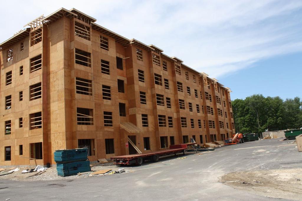
5 Following the load Multi-Story Wood Design Photo credit: Matt Todd & PB Architects
6 Load Path Continuity Karuna I Holst Architecture Photo credit: Matt Todd & PB Architects Photo: Terry Malone
7 Multi-Story Considerations Wind Load Paths Multi-Story Stacked Shear Wall Effects Accumulation of Overturning Loads Shear Wall Deflection Diaphragm Modeling Discontinuous Shear Walls

8 Wind Load Distribution to Shearwalls

9 Wind Load Distribution to Shearwalls

10 Wind Load Distribution to Shearwalls Photo credit: Matt Todd & PB Architects
11 Multi-Story Wind Load Design Design Principles are the Same Remember to: FOLLOW THE LOAD! Photo credit: Matt Todd & PB Architects
12 Multi-Story Wind Load Design WIND SURFACE LOADS ON WALLS

13 Multi-Story Wind Load Design WIND INTO DIAPHRAGMS AS UNIFORM LINEAR LOADS
14 Multi-Story Wind Load Design DIAPHRAGMS SPAN BETWEEN SHEARWALLS WIND INTO SHEARWALLS AS CONCENTRATED LOADS
15 Multi-Story Wind Load Design DIAPHRAGM WIND FORCES DO NOT ACCUMULATE-THEY ARE ISOLATED AT EACH LEVEL SHEARWALL WIND FORCES DO ACCUMULATE-UPPER LEVEL FORCES ADD TO LOWER LEVEL FORCES

16 Design Example: Five Over One Wood Frame Free download at woodworks.org
17 Multi-Story Wind Design Source: WoodWorks Five-Story Wood-Frame Structure over Podium Slab Design Example Floor Plan


18 Multi-Story Wind Design Source: WoodWorks Five-Story Wood-Frame Structure over Podium Slab Design Example Shearwall Layout Shearwall design we ll look at
19 Multi-Story Wind Design Source: WoodWorks Five-Story Wood-Frame Structure over Podium Slab Design Example Shearwall Layout
20 Components of Shear Wall Design F 5 = 5.2k F 4 = 3.8k F 3 = 3.7k F 2 = 3.6k F 1 = 3.4k 10-0 Typ Typ. Shear Wall Elevation Wind Forces Per Story
21 Components of Shear Wall Design F = 5.2k F = 9k F = 12.7k F = 16.3k 10-0 Typ. F = 19.7k 29-0 Typ. Shear Wall Elevation Accumulated Wind Forces
22 Components of Shear Wall Design Tension Compression Holdown Boundary Posts Anchorage Overturning Resistance
23 Overturning Force Calculation F = 5.2k F = 12.7k F = 16.3k F = 9k 9.6k 5.1k 1.9k T = C = F*h/L T & C are cumulative at lower stories F = 19.7k 15.4k h L is moment arm, not 22.5k entire wall Assume L = 29ft-1ft = 28ft L length

24 Sole Plate Crushing
25 Sole Plate Crushing Compression forces perpendicular to grain can cause localized wood crushing. NDS values for with metal plate bearing on wood result in a maximum wood crushing of Relationship is non-linear
26 Compression Post Size & Sole Plate Crush Level Compression Required Bearing Area Post Size Story Sole Plate Crush 5x Sole Plate Crush 5 th Floor 1.9 k 4.4 in 2 (2)-2x th Floor 5.1 k 11.9 in 2 (2)-4x rd Floor 9.6 k 22.6 in 2 (2)-4x nd Floor 15.4 k 36.3 in 2 (3)-4x st Floor 22.5 k 39.8 in 2 (4)-4x Floors 2-5 use S-P-F #2 Sole Plate, F cperp = 425 psi Floor 1 use SYP #2 Sole Plate, F cperp = 565 psi

27 Story to Story Compression Force Transfer Source: WoodWorks Five-Story Wood-Frame Structure over Podium Slab Design Example

28 Rim Joist Buckling & Crushing

29 Increasing Compression Post Size Source: WoodWorks Five-Story Wood-Frame Structure over Podium Slab Design Example
30 Overturning Tension Tension Compression Equal and Opposite Forces
 can be used to resist some or all overturning forces, depending")
31 Using Dead Load to Resist Overturning Load Combinations of ASCE 7-10: 06.D + 0.6W Dead load from above (Wall, Floor, Roof) can be used to resist some or all overturning forces, depending on magnitude Source: Strongtie

32 Shear Wall Holdown Options Strap Holdown Installation 6+ kip story to story capacities Standard Holdown Installation 13+ kip capacities Continuous Rod Tiedown Systems 100+ kip capacities 20+ kips/level
33 Components of Shear Wall Design F = 5.2k F = 9k F = 12.7k F = 16.3k F = 19.7k 1.9k 1.9k 3.2k 5.1k 4.5k 9.6k 5.8k 15.4k 7.1k 22.5k Continuous Rod Holdown System Overturning restraint at bearing plate at top of story Tension accumulates in rod. Bearing plates see local overturning only. Tension zone boundary framing in compression!


34 Threaded Rod Tie Down w/take Up Device Source: Strongtie Source: hardyframe.com

35 Threaded Rod Tie Down w/o Take Up Device
36 Tie Down Rod Size & Elongation Level Plate Hght Tension Rod Dia. Steel Rod Capacity Rod Elong. 5 th Floor 4 th Floor 3 rd Floor 2 nd Floor 1 st Floor 10 ft 1.9 k 3/8 A k ft 5.1 k 5/8 A k ft 9.6 k 5/8 A k ft 15.4 k 3/4 A k ft 22.5 k 7/8 A k 0.2

37 Bearing Plate Crushing
38 Bearing Plate Size & Thickness Level 5 th Floor 4 th Floor 3 rd Floor 2 nd Floor 1 st Floor Bearing Plate W L T Hole Area A brng Bearing Load Allow. Bearing Capacity Bearing Plate Crush 3 in 3.5 in 3/ in in k 4.4 k in 3.5 in 3/ in in k 4.2 k in 5.5 in 1/ in in k 6.8 k in 5.5 in 1/ in in k 6.7 k in 8.5 in 7/ in in k 10.4 k 0.014
39 Shearwall Deformation System Stretch Total system stretch includes: Rod Elongation Take-up device displacement Bearing Plate Crushing Sole Plate Crushing Source: WoodWorks Five-Story Wood-Frame Structure over Podium Slab Design Example
40 Accumulative Movement With Shrinkage Compensating Devices Level 5 th Floor 4 th Floor 3 rd Floor 2 nd Floor 1 st Floor Rod Elong. Shrinkage Sole Plate Crush Bearing Plate Crush Take Up Deflect. Elong. Total Displac
41 Shear Wall Deflection Deflection SDPWS 2008 Eq SDPWS 2008 Eq. C IBC 2000 to 2015 Eq Bending of boundary elements
42 Shear Wall Deflection Deflection SDPWS 2008 Eq SDPWS 2008 Eq. C IBC 2000 to 2015 Eq Shear Deformation of Sheathing Panels & Slip of panel to panel connections
43 Shear Wall Deflection Deflection SDPWS 2008 Eq h SDPWS 2008 Eq. C Δ a b IBC 2000 to 2015 Eq Rigid Body Rotation
44 Shearwall Deflection Level Unit Shear End Post A End Post E Ga Total Displace. Deflection 5 th Floor 4 th Floor 3 rd Floor 2 nd Floor 1 st Floor 179 plf 10.5 in ksi 310 plf 24.5 in ksi 438 plf 24.5 in ksi 562 plf 36.8 in ksi 679 plf 49 in ksi 10 k/in k/in k/in k/in k/in
45 Shearwall Deflection Methods Multiple methods for calculating accumulative shearwall deflection exist Mechanics Based Approach: Uses single story deflection equation at each floor Includes rotational & crushing effects Uses SDPWS 3 part equation Other methods exist which use alternate deflection equations, FEM
46 Shearwall Deflection Criteria for Wind Unlike seismic, no code information exists on deflection/drift criteria of structures due to wind loads Allowable =? Serviceability check to minimize damage to cladding and nonstructural walls ASCE 7-10: C.2.2 Drift of Walls and Frames. Lateral deflection or drift of structures and deformation of horizontal diaphragms and bracing systems due to wind effects shall not impair the serviceability of the structure. What wind force should be used? What drift criteria should be applied?
47 Shearwall Deflection Criteria for Wind Wind Forces Consensus is that ASD design level forces are too conservative for building/frame drift check due to wind Commentary to ASCE 7-10 Appendix C suggests that some recommend using 10 year return period wind forces: ~ 70% of 700 return period wind (ultimate wind speed for risk category II buildings) Others (AISC Design Guide 3) recommend using 75% of 50 year return period forces Drift Criteria Can vary widely with brittleness of finishes but generally recommendations are in the range of H/240 to H/600
48 Diaphragm Modeling Methods Not using all shared walls for Shear A B C Typical Unit D Robust Diaphragm Aspect Ratio Possible Shear Wall Layouts
49 Diaphragm Modeling Methods A B C Typical Unit D Robust Diaphragm Aspect Ratio Possible Shear Wall Layouts But maybe not much wall available on exterior
50 Rigid or Flexible Diaphragm? Light Frame Wood Diaphragms often default to Flexible Diaphragms Code Basis: ASCE Definitions (Wind) Diaphragms constructed of wood structural panels are permitted to be idealized as flexible Code Basis: ASCE (Seismic) Diaphragms constructed of untopped steel decking or wood structural panels are permitted to be idealized as flexible if any of the following conditions exist: [ ] c. In structures of light-frame construction where all of the following conditions are met: 1. Topping of concrete or similar materials is not placed over wood structural panel diaphragms except for nonstructural topping no greater than 1 1/2 in. thick. 2. Each line of vertical elements of the seismic force resisting system complies with the allowable story drift of Table
51 Area tributary to corridor wall line 23% A 27% 27% 23% Large portion of load on little wall Hypothetical Flexible Diaphragm Distribution Typical Unit Changing wall construction does NOT impact load to wall line B C D Area tributary to exterior wall line
52 Longer, stiffer walls receive more load 10% A 40% 40% 10% Narrow, flexible walls receive less load Hypothetical Rigid Diaphragm Distribution Typical Unit Changing wall construction impacts load to wall line B C D Diaphragm assumed to be rigid body.
53 Can a Rigid Diaphragm be Justified? ASCE (Seismic) [Diaphragms] are permitted to be idealized as flexible where the computed maximum in-plane deflection of the diaphragm under lateral load is more than two times the average story drift of adjoining vertical elements of the seismic force-resisting system of the associated story under equivalent tributary lateral load as shown in Fig IBC 2012 Chapter 2 Definition (Wind & Seismic) A diaphragm is rigid for the purpose of distribution of story shear and torsional moment when the lateral deformation of the diaphragm is less than or equal to two times the average story drift. Average drift of walls Maximum diaphragm deflection
54 Rigid Diaphragm Analysis Some Advantages of Rigid Diaphragm More load (plf) to longer interior/corridor walls Less load (plf) to narrow walls where overturning restraint is tougher Can tune loads to walls and wall lines by changing stiffness of walls Some Disadvantages of Rigid Diaphragm Considerations of torsional loading necessary More complicated calculations to distribute load to shear walls May underestimate Real loads to narrow exterior walls Justification of rigid assumption
55 Two More Diaphragm Approaches Semi-Rigid Diaphragm Analysis Neither idealized flexible nor idealized rigid Explicit modeling of diaphragm deformations with shear wall deformations to distribute lateral loads Not easy. Enveloping Method Idealized as BOTH flexible and rigid. Individual components designed for worst case from each approach Been around a while, officially recognized in the 2015 SDPWS
56 A B C Typical Unit D Possible Shear Wall Layouts The Cantilever Diaphragm Option
57 A B C Typical Unit D Robust Aspect Ratio but only supported on 3 sides Possible Shear Wall Layouts
58 Cantilevered Diaphragms in SDPWS 2008 Open Front Structure Cantilever Diaphragm AWC SDPWS 2008 Figure 4A AWC SDPWS 2008 Figure 4B
59 Cantilevered Diaphragms in SDPWS 2008 Open Front Structure SDPWS L 25 ft L/W 1, one story 2/3, multi-story Exception: Where calculations show the diaphragm deflections can be tolerated, the length, L, can be increased to L/W 1.5 for WSP sheathed diaphragms.
60 Cantilevered Diaphragms in SDPWS 2008 Cantilevered Diaphragm SDPWS Lc 25 ft Lc/W 2/3
61 A B C Typical Unit D Open Front Structure or Cantilevered Diaphragm? Possible Shear Wall Layouts
62 Cantilevered Diaphragms in SDPWS 2015 Open Front Structure with a Cantilevered Diaphragm AWC SDPWS 2015 Figure 4A
63 Open Front Structure & Cantilevered Diaphragms in SDPWS 2015 Cantilevered Diaphragm SDPWS L /W 1.5 When Torsionally Irregular L /W 1, one story L 35 ft 2/3, multi-story Provided diaphragms modelled as rigid or semi-rigid and for seismic, the story drift at each edge of the structure within allowable story drift of ASCE 7. Story drifts include torsion and accidental torsional loads and deformations of the diaphragm.

64 Wind Load Distribution to Shearwalls

65 Tie Down Attachment to Concrete Source: Strongtie

66 Tie Down Bolt with Washer Source: Strongtie
67 Tie Down Bolt with Washer - Reinforcing Source: Strongtie


68 Embedded Steel Plates Weld on Rods

69 Tie Down Anchors Precast Through Bolt

70 Tie Down Anchors Through Podium
71 Discontinuous Shear Walls Karuna I Holst Architecture Photo credit: Matt Todd & PB Architects Photo: Terry Malone

72 Offset Shear Wall Overturning Resistance Source: Strongtie


73 Tie Down to Steel Beam Attachment Source: Strongtie
74 Tie Down to Steel Beam Attachment

75 Shear Wall to Podium Slab Interface ASCE 7-10 Section and Commentary C provides guidance on seismic load requirements for various elements supporting discontinuous shear walls
76 Recap Wind Load Paths Multi-Story Stacked Shear Wall Effects Accumulation of Overturning Loads Shear Wall Deflection Diaphragm Modeling Discontinuous Shear Walls
77 Questions? This concludes The American Institute of Architects Continuing Education Systems Course Ricky McLain, MS, PE, SE WoodWorks (802) Visit for more educational materials, case studies, design examples, a project gallery, and more
78 Copyright Materials This presentation is protected by US and International Copyright laws. Reproduction, distribution, display and use of the presentation without written permission of the speaker is prohibited. The Wood Products Council 2016
Lateral load basics Code acceptance of Standard. Standard Overview 2008 Wind & Seismic Standard. Wind. Wind Load Path. IBC Section 1604.
 Outline 2005/2008 Special Design Provisions for Wind & Seismic Standard Lateral load basics Code acceptance of Standard 2005/2008 Wind & Seismic Standard Overview 2008 Wind & Seismic Standard John Buddy
Lateral Design Considerations for Mid-Rise Wood Structures
 Lateral Design Considerations for Mid-Rise Wood Structures 120 Union, San Diego, CA Togawa Smith Martin By: R. Terry Malone, PE, SE Senior Technical Director Architectural & Engineering Solutions www.woodworks.org
Significant Changes to AWC s Special Design Provisions for Wind and Seismic
 Significant Changes to AWC s Special Design Provisions for Wind and Seismic Michelle Kam-Biron, PE, SE, SECB Director of Education American Wood Council Copyright Materials This presentation is protected
2015 Special Design Provisions for Wind and Seismic Philip Line, P.E., John Buddy Showalter, P.E., Michelle Kam-Biron, P.E., S.E., Jason Smart, P.E.
 2015 Special Design Provisions for Wind and Seismic Philip Line, P.E., John Buddy Showalter, P.E., Michelle Kam-Biron, P.E., S.E., Jason Smart, P.E. The 2015 Edition of Special Design Provisions for Wind
Structural Design for Wind Loads: An Overview of Engineering Considerations for Wood
 Structural Design for Wind Loads: An Overview of Engineering Considerations for Wood Lori Koch, PE Manager, Educational Outreach American Wood Council Buildings Copyright Materials This presentation is
Learning Objectives. Copyright Materials. This presentation is protected by US and International Copyright laws. Reproduction,
 The Wood Products Council is a Registered Provider with The American Institute of Architects Continuing Education Systems (AIA/CES). Credit(s) earned on completion of this program will be reported to AIA/CES
Wood Solutions Fair, 2014, Toronto
 Overview of Changes to CSA O86-2014 & Structural Design Provisions for Mid-Rise in OBC Wood Solutions Fair, 2014, Toronto Jasmine Wang, Ph.D., P.Eng. Canadian Wood Council Copyright Materials This presentation
Designing Wood Frame Structures For High Winds. Ricky McLain, MS, PE, SE Technical Director WoodWorks SEAMASS Meeting
 Designing Wood Frame Structures For High Winds Ricky McLain, MS, PE, SE Technical Director WoodWorks SEAMASS Meeting 10-26-16 Overview Wind Loads and Code Changes Uplift Wall Design Diaphragms Shearwalls
WHITE PAPER March 7, 2013
 Liaison Committee Washington Association of Building Officials and Structural Engineers Association of Washington March 7, 2013 Abstract: This white paper establishes guidelines for specifications for
Shaft Wall Solutions for Wood-Frame Structures. Ricky McLain, PE, SE WoodWorks Wood Products Council Boston & Waltham Workshops, December 6 & 7, 2017
 Shaft Wall Solutions for Wood-Frame Structures Ricky McLain, PE, SE WoodWorks Wood Products Council Boston & Waltham Workshops, December 6 & 7, 2017 Shaft Walls Shaft Walls Form Shaft Enclosures The purpose
[TECHNICAL REPORT 3] Lateral System Analysis
![[TECHNICAL REPORT 3] Lateral System Analysis](/thumbs/96/126531717.jpg "[TECHNICAL REPORT 3] Lateral System Analysis") Science Center Research Park 3711 Market St. The Pennsylvania State University Department of Architectural Engineering Senior Thesis 2009-2010 Prepared by: November 30, 2009 [TECHNICAL REPORT 3] Lateral
Science Center Research Park 3711 Market St. The Pennsylvania State University Department of Architectural Engineering Senior Thesis 2009-2010 Prepared by: November 30, 2009 [TECHNICAL REPORT 3] Lateral
Special Inspections for Wood Construction BCD710 Michelle Kam-Biron, PE, SE, SECB Senior Director, Education American Wood Council
 Special Inspections for Wood Construction BCD710 Michelle Kam-Biron, PE, SE, SECB Senior Director, Education American Wood Council Copyright Materials This presentation is protected by US and International
Mandatory Wood Frame Soft-story Retrofit Program STRUCTURAL DESIGN GUIDELINES
 INFORMATION BULLETIN / PUBLIC - BUILDING CODE REFERENCE NO.: LAMC Division 93 Effective: 11/22/15 DOCUMENT NO.: P/BC 2014-137 Revised: 06/07/16 Previously Issued As: N/A Mandatory Wood Frame Soft-story
A REPORT ON THE EFFECTS OF WIND SPEED ON TIMBER CONSTRUCTION JOSHUA HUENEFELD. B.S., Kansas State University, 2012 A REPORT
 A REPORT ON THE EFFECTS OF WIND SPEED ON TIMBER CONSTRUCTION by JOSHUA HUENEFELD B.S., Kansas State University, 2012 A REPORT submitted in partial fulfillment of the requirements for the degree MASTER
Recent Advances in Seismic and Wind Design of Wood Structures &Historic Preservation Examples
 SEAoA 2015 Conference and Convention Recent Advances in Seismic and Wind Design of Wood Structures &Historic Preservation Examples Kelly Cobeen Wiss Janney Elstner Associates, Inc. Seminar Outline 1. NEHRP
4.6 Procedures for Connections
 4.6 Procedures for Connections This section provides Tier 2 evaluation procedures that apply to structural connections: anchorage for normal forces, shear transfer, vertical components, interconnection
Shaft Wall Solutions for Wood-Frame Structures. Ricky McLain, PE, SE WoodWorks Wood Products Council Charlotte WSF, November 2, 2017
 Shaft Wall Solutions for Wood-Frame Structures Ricky McLain, PE, SE WoodWorks Wood Products Council Charlotte WSF, November 2, 2017 Course Description It is fairly common for light wood-frame commercial
Lateral System Analysis and Confirmation Design
 Andrew Covely Structural Dr. Linda Hanagan The Helena New York City, NY November 15, 2004 Pictures courtesy of Fox & Fowle Architects Lateral System Analysis and Confirmation Design Executive Summary This
VOLUNTARY - EARTHQUAKE HAZARD REDUCTION IN EXISTING HILLSIDE BUILDINGS (Division 94 Added by Ord. No. 171,258, Eff. 8/30/96.)
") DIVISION 94 VOLUNTARY - EARTHQUAKE HAZARD REDUCTION IN EXISTING HILLSIDE BUILDINGS (Division 94 Added by Ord. No. 171,258, Eff. 8/30/96.) SEC. 91.9401. PURPOSE. (Amended by Ord. No. 172,592, Eff. 6/28/99,
DIVISION 94 VOLUNTARY - EARTHQUAKE HAZARD REDUCTION IN EXISTING HILLSIDE BUILDINGS (Division 94 Added by Ord. No. 171,258, Eff. 8/30/96.) SEC. 91.9401. PURPOSE. (Amended by Ord. No. 172,592, Eff. 6/28/99,
CVEN 483. Structural System Overview
 CVEN 483 Structural System Overview Dr. J. Bracci Fall 2001 Semester Presentation Overview 1. Building system primary function 2. Types of load 3. Building materials 4. Structural members 5. Structural
WELCOME! Copyright Materials. Credit Information. Welcome! We will begin in a few minutes. by the sign in table for today s drawing.
 WELCOME! Welcome! We will begin in a few minutes. Please drop a business card or name card in the bowl d d i b l by the sign in table for today s drawing. Copyright Materials This presentation is protected
2012 Wood Frame Construction Manual: Wind Load Distribution on Buildings Load Paths
 2012 Wood Frame Construction Manual: Wind Load Distribution on Buildings Load Paths Presented by: William L. Coulbourne, PE Copyright Materials This presentation is protected by US and International Copyright
Considerations for Outof-Plane. Design
 Considerations for Outof-Plane Wall and Uplift Design WoodWorks Texas Workshops December, 2016 Overview Uplift Wall Design Wind Loads Wind loads acting on buildings are modeled as uniform surface loads.
Structural Training - Part 1:
 Structural Training - Part 1: Structural Training Residential Wood-Framed Construction Presented by: City of Santa Clarita Building & Safety Division February, 2014 The information provided in this presentation
Question 8 of 55. y 24' 45 kips. 30 kips. 39 kips. 15 kips x 14' 26 kips 14' 13 kips 14' 20' Practice Exam II 77
 Question 8 of 55 A concrete moment frame building assigned to SDC = D is shown in the Figure. Equivalent lateral force analysis procedure is used to obtain the seismic lateral loads, E h, as shown. Assume
Xyston Inn. NY. Proposal. Xiaodong Jiang. Structure Option. Advisor: Dr. Linda Hanagan
 Proposal Xiaodong Jiang Structure Option Advisor: Dr. Linda Hanagan December 12, 2014 Executive Summary Xyston Inn is a 17-story hotel building that will be located in Brooklyn, New York. The design of
Two Stage Analysis Procedure: Wood on Podium Design
 Two Stage Analysis Procedure: Wood on Podium Design Part 1: Flexible Upper Portion Jared Cope, S.E. Two Stage Analysis Procedure: Wood on Podium Design 1 Two Stage Analysis: ASCE 7-10 Chapter 12 12.2.3.2
WIND & SEISMIC 2008 EDITION ASD/LRFD WITH COMMENTARY. American Forest & Paper Association. American Wood Council ANSI/AF&PA SDPWS-2008
 2008 EDITION ANSI/AF&PA SDPWS-2008 Approval Date: August 4, 2008 ASD/LRFD WIND & SEISMIC Special Design Provisions for Wind and Seismic WITH COMMENTARY American Forest & Paper Association American Wood
SDPWS. Special Design Provisions for Wind & Seismic 2015 EDITION
 SDPWS Special Design Provisions for Wind & Seismic 2015 EDITION ANSI/AWC SDPWS-2015 Approval date September 8, 2014 Updates and Errata While every precaution has been taken to ensure the accuracy of this
Pulaski County, Virginia Practical Wall Bracing
 Pulaski County, Virginia Practical Wall Bracing Based on the 2012 Virginia Residential Code The information herein provides guidelines for complying with the most common Practical Wall Bracing provisions
6-Story Wood Frame Committee
 6-Story Wood Frame Committee Fourth (A) Draft Report March 14 th 2009 1. INTRODUCTION 1.1 PURPOSE This technical bulletin provides basic guidance on structural, fire protection and building envelope engineering
SE APPRENTICE. Today s Speakers. Lateral Load Systems. Lateral Loads
 Today s Speakers Carrie Bremer, PE Schaefer Stephen Metz, PE SMBH, Inc. Today s Moderators SE APPRENTICE Lecture Two- Systems & Paths Lisa Willard, PE SE Solutions, LLC SE Apprentice Brian Quinn, PE SE
SEAU 5 th Annual Education Conference 1. ASCE Concrete Provisions. Concrete Provisions. Concrete Strengths. Robert Pekelnicky, PE, SE
 ASCE 41-13 Concrete Provisions Robert Pekelnicky, PE, SE Principal, Degenkolb Engineers Chair, ASCE 41 Committee* *The view expressed represent those of the author, not the standard s committee as a whole.
WIND & SEISMIC 2008 EDITION ASD/LRFD WITH COMMENTARY. American Forest & Paper Association. American Wood Council ANSI/AF&PA SDPWS-2008
 2008 EDITION ANSI/AF&PA SDPWS-2008 Approval Date: August 4, 2008 ASD/LRFD WIND & SEISMIC Special Design Provisions for Wind and Seismic WITH COMMENTARY American Forest & Paper Association Updates and Errata
COPYRIGHT MATERIALS. Wind Solutions - Perforated Wood Structural Panel Shear Walls (DES 416)
") Wind Solutions - Perforated Wood Structural Panel Shear Walls (DES 416) Lori Koch, M.S., M.F., P.E. Manager, Educational Outreach American Wood Council Adam Robertson, M.A.Sc., P.Eng. Manager, Codes and
Wind Solutions - Perforated Wood Structural Panel Shear Walls (DES 416) Lori Koch, M.S., M.F., P.E. Manager, Educational Outreach American Wood Council Adam Robertson, M.A.Sc., P.Eng. Manager, Codes and
Xyston Inn. NY. Proposal. Xiaodong Jiang. Structure Option. Advisor: Dr. Linda Hanagan
 Proposal Xiaodong Jiang Structure Option Advisor: Dr. Linda Hanagan December 12, 2014 Executive Summary Xyston Inn is a 17-story hotel building that will be located in Brooklyn, New York. The design of
Diaphragms 2. Design Process. Design Process. Diaphragms are the roofs and floors of the upper stories
 Diaphragms 2 Design Process Diaphragms are the roofs and floors of the upper stories They are assumed to act as a beam (usually a deep beam with substantial shear deformation) Design Process Sheathing
Table 3. Detailed Comparison of Structural Provisions of IRC 2000 and 1997 NEHRP (Continued)
") 2000 IRC 1997 NEHRP Section Provision Section Provision Comments CHAPTER 3 BUILDING PLANNING R301 DESIGN CRITERIA R301.2.2 Seismic Provisions R301.2.2.1 Determination of Seismic Design Category R301.2.2.1.1
2000 IRC 1997 NEHRP Section Provision Section Provision Comments CHAPTER 3 BUILDING PLANNING R301 DESIGN CRITERIA R301.2.2 Seismic Provisions R301.2.2.1 Determination of Seismic Design Category R301.2.2.1.1
MOUNTAIN STATE BLUE CROSS BLUE SHIELD HEADQUARTERS
 MOUNTAIN STATE BLUE CROSS BLUE SHIELD HEADQUARTERS PARKERSBURG, WEST VIRGINIA DOMINIC MANNO STRUCTURAL OPTION FACULTY CONSULTANT: DR. ANDRES LEPAGE Technical Report 3 11-21-08 TABLE OF CONTENTS TABLE OF
Attachment A. USG Minimum Design and Construction Requirements for Wood Framed Structures
 Attachment A USG Minimum Design and Construction Requirements for Wood Framed Structures 1. General Design Criteria 1.1. Per Adopted Georgia State Minimum Standard Building Code 1.2. Minimum Live Loads
WOOD STRUCTURES Objectives of Topic
 WOOD STRUCTURES Objectives of Topic Understanding of: Basic wood behavior Typical framing methods Main types of lateral force resisting systems Expected response under lateral loads Sources of strength,
Check the strength of each type of member in the one story steel frame building below.
 CE 331, Summer 2015 nalysis of Steel Braced Frame Bldg 1 / 9 Check the strength of each type of member in the one story steel frame building below. 4 @ 8 ft B 20 f 1 2 3 @ 25 ft Side Elevation 3 4 Plan
Point Pleasant Apartments Point Pleasant, NJ Ryan P. Flynn Structural Option Faculty Consultant: Dr. Hanagan
 Point Pleasant Apartments Point Pleasant, NJ Ryan P. Flynn Structural Option Faculty Technical Report #3: Lateral System Analysis and Confirmation Design Table of Contents Introduction... 3 Executive Summary...
Structural System. Design Criteria Fire Resistance Concrete designed for 2 HR rating (worst case) Geotechnical Report Allowable Bearing Capacity
 Geotechnical Report Allowable Bearing Capacity") System Codes and Criteria Design Codes and Standards The design code used is the Wisconsin Administrative Code along with the State of Wisconsin Department of Commerce-Safety & Buildings Chapters Comm
System Codes and Criteria Design Codes and Standards The design code used is the Wisconsin Administrative Code along with the State of Wisconsin Department of Commerce-Safety & Buildings Chapters Comm
Originally Issued: 02/11/2011 Revised: 02/23/2018 Valid Through: 02/28/2019
 MITEK USA, INC. USP HOLDOWN AND TENSION-TIE CONNECTORS CSI Section: 06 05 23 Wood, Plastic and Composite Fastenings 1.0 RECOGNITION MiTek USA, Inc. USP holdown and tension-tie connectors recognized in
REPORT HOLDER: FASTENING SPECIALISTS, INC. 726 CENTRAL FLORIDA PARKWAY ORLANDO, FLORIDA EVALUATION SUBJECT:
 0 Most Widely Accepted and Trusted ICC ES Evaluation Report ICC ES 000 (800) 423 6587 (562) 699 0543 www.icc es.org ESR 2328 Reissued 10/2017 This report is subject to renewal 10/2018. DIVISION: 03 00
Copyright Materials. American Wood Council
 2012 Wood Frame Construction Manual: Foundation Design to Resist Flood Loads and WFCM Calculated Wind Loads Presented by: William L. Coulbourne, PE 2 Copyright Materials This presentation is protected
RCKW Kneewall Connectors
 This product is preferable to similar connectors because of a) easier installation, b) higher loads, c) lower installed cost, or a combination of these features. The Simpson Strong-Tie RCKW rigid connectors
On Cold-Formed Steel Construction. Light Gauge Steel Engineers Association Washington, D.C Toll Free (866)
") TECHNICAL NOTE On Cold-Formed Steel Construction $5.00 Light Gauge Steel Engineers Association Washington, D.C. 20005 Toll Free (866) 465-4732 www.lgsea.com DESIGN OF BY-PASS SLIP CONNECTORS IN COLD-FORMED
TECHNICAL NOTE On Cold-Formed Steel Construction $5.00 Light Gauge Steel Engineers Association Washington, D.C. 20005 Toll Free (866) 465-4732 www.lgsea.com DESIGN OF BY-PASS SLIP CONNECTORS IN COLD-FORMED
fifteen design for lateral loads Lateral Load Resistance Load Direction Lateral Load Resistance
 APPLIED ARCHITECTURAL STRUCTURES: STRUCTURAL ANALYSIS AND SYSTEMS DR. ANNE NICHOLS FALL 2013 lecture fifteen design for lateral loads Lateral Load Resistance stability important for any height basic mechanisms
Z4 PRODUCT CATALOG
 Z4 PRODUCT CATALOG 08-01-17 At MiTek, we believe that better processes can empower your business; and we ve learned three important things over the years: We ve learned that when people collaborate well,
North Shore at Canton Baltimore, MD Beau Menard Technical Report 1
 North Shore at Canton Baltimore, MD Beau Menard Technical Report 1 Structural Schneider 10/05/05 Structural Concepts Executive Summary North Shore at Canton is a 4 story town home and parking garage structure
Lateral System Analysis Study
 Lateral System Analysis Study Prince Frederick Hall The University of Maryland College Park, MD Christopher Cioffi AE Senior Thesis- Structural Advisor: Heather Sustersic Table of Contents General Information...
Lateral System Analysis and Confirmation Design November 15, 2004
 Jonathan Hill Structural AE Faculty Consultant Dr. Hanagan Lynde and Harry Bradley School of Technology & Trade Milwaukee, Wisconsin Lateral System Analysis and Confirmation Design November 15, 2004 Executive
Copyright Materials. R. Jonkman, P.Eng, A. Robertson, P.Eng 1
 Robert Jonkman, P.Eng. November 12, 2013 Adam Robertson, P.Eng. Toronto Wood Solutions Fair Copyright Materials This presentation is protected by US and International Copyright laws. Reproduction, distribution,
Structural Engineering, Mechanics, and Materials. Preliminary Exam - Structural Design
 Fall Semester 2018 Preliminary Exam - Structural Design A small building is located in downtown Berkeley. The structural system, either structural steel or reinforced concrete, comprises gravity framing
Cross-Laminated Timber (CLT) in California: Guidelines, Testing and Recommendations
 in California: Guidelines, Testing and Recommendations") Cross-Laminated Timber (CLT) in California: Guidelines, Testing and Recommendations Presented by Scott Breneman, PhD, PE, SE Senior Technical Director Scott.Breneman@woodworks.org 1 The Wood Products Council
Cross-Laminated Timber (CLT) in California: Guidelines, Testing and Recommendations Presented by Scott Breneman, PhD, PE, SE Senior Technical Director Scott.Breneman@woodworks.org 1 The Wood Products Council
Chapter 2 EARTHQUAKE-RESISTANCE REQUIREMENTS
 Chapter 2 EARTHQUAKE-RESISTANCE REQUIREMENTS This chapter explains the International Residential Code s (IRC s) general earthquake-resistance requirements as well as specific IRC requirements concerning
Residential Wood Deck Design
 Residential Wood Deck Design EARN 0.1 ICC Continuing Education Unit (CEU) and/or AIA/CES HSW 1 Learning Unit (LU) BCD303-A Residential Wood Deck Design Description: Deck and balcony collapses injure occupants
4.2 Tier 2 Analysis General Analysis Procedures for LSP & LDP
 4.2 Tier 2 Analysis 4.2.1 General Four analysis procedures are provided in this section: Linear Static Procedure (LSP), Linear Dynamic Procedure (LDP), Special Procedure, and Procedure for Nonstructural
fifteen design for lateral loads Lateral Load Resistance Load Direction Lateral Load Resistance
 APPLIED ARCHITECTURAL STRUCTURES: STRUCTURAL ANALYSIS AND SYSTEMS DR. ANNE NICHOLS SPRING 2017 lecture fifteen design for lateral loads Lateral Load Resistance stability important for any height basic
fifteen design for lateral loads Lateral Load Resistance Load Direction Lateral Load Resistance
 APPLIED ARCHITECTURAL STRUCTURES: STRUCTURAL ANALYSIS AND SYSTEMS DR. ANNE NICHOLS FALL 2014 lecture fifteen design for lateral loads Lateral Load Resistance stability important for any height basic mechanisms
CE 549 Building Design Project Spring Semester 2010
 CE 549 Building Design Project Spring Semester 2010 Instructor: Farzad Naeim, Ph.D., S.E., Esq. E-Mail: naeim@usc.edu Syllabus Overview: We will design a mid-rise office building using a team-approach
Danielle Shetler - Structural option Courtyard by Marriott Lancaster, PA
 Structural Analysis Overview: During the structural analysis of the in Lancaster, Pa, a redesign of the lateral and gravity system from masonry bearing and shear walls to a staggered truss system was performed.
ENTRY FORM. DVASE 2014 Excellence in Structural Engineering Awards Program
 ENTRY FORM DVASE 2014 Excellence in Structural Engineering Awards Program PROJECT CATEGORY (check one): Buildings under $2M Buildings Over $100M Buildings $2M-$10M Other Structures Under $5M Buildings
Hilton Baltimore Convention Center Hotel Western Podium
 Hilton Baltimore Convention Center Hotel Western Podium CHRIS SIMMONS Structural Option Faculty Consultant: Dr. Ali M. Memari Technical Report 1 TABLE OF CONTENTS EXECUTIVE SUMMARY. Page 3 INTRODUCTION..
Shaft Wall Solutions for Wood-Frame Structures. Ricky McLain, PE, SE WoodWorks Wood Products Council Atlanta WSF, April 25, 2018
 Shaft Wall Solutions for Wood-Frame Structures Ricky McLain, PE, SE WoodWorks Wood Products Council Atlanta WSF, April 25, 2018 Course Description It is fairly common for light wood-frame commercial and
CBC SECTION/TABLE NUMBER NEW -CHANGE COMMENTARY. X Flexible and Rigid definitions removed and found in ASCE 7-10
 2016 Chapter 16 Structural Design- Changes include new plan content requirements for Photovoltaic Panel Systems as well as guidance on how to determine the dead and live loads. For mid- and high-rise designs
CE 549 Building Design Project Spring Semester 2013
 CE 549 Building Design Project Spring Semester 2013 Instructor: Farzad Naeim, Ph.D., S.E., Esq. E-Mail: naeim@usc.edu Syllabus Overview: We will design a mid-rise office building using a team-approach
Trusted ICC ES TEK USA, Evaluation. report, or as to any. ICC-ES Evaluation
 0 ICC ES Evaluation Report ICC ES 000 (800) 423 6587 (562) 699 0543 www.icc es.orgg Most Widely Accepted and Trusted ESR 3105 Reissued 08/2017 Revised 10/2018 This report is subject to renewal 08/2019.
Steel Roof Deck EC X
 IAPMO ES Cover Sheet Evaluation Criteria of Steel Roof Deck EC 007-200 Posted for public commenting on 10/16/2009 to 11/12/2009 INTERNATIONAL ASSOCIATION OF PLUMBING AND MECHANICAL OFFICIALS, EVALUATION
Alexis Pacella Structural Option Dr. Schneider Lexington II, Washington D.C. Technical Report #3 November 21,
 1 Executive Summary: Lateral System Analysis and Confirmation Design is an depth look at the lateral system of Lexington II and the loads of which it must carry. The structural system of Lexington II is
John Jay College Expansion Project
 Technical Report #3 Michael Hopper Mike AE Consultant: Dr. Lepage [Type the company name] November 21 st, 2008 Technical Report #3 Table of Contents Executive Summary.3 Introduction.4 Existing Composite
DIVISION: WOOD, PLASTICS AND COMPOSITES SECTION: SHEAR WALL PANELS REPORT HOLDER: TRUSSED, INC. EVALUATION SUBJECT:
 0 ICC-ES Evaluation Report ICC-ES 000 (800) 423-6587 (562) 699-0543 www.icc-es.org Most Widely Accepted and Trusted ESR-2807 Reissued 07/2018 Revised 08/2018 This report is subject to renewal 05/2019.
Composite Steel/Concrete
 Composite Steel/Concrete Composite Steel and Concrete Clinton O. Rex, P.E., PhD Originally developed by James Robert Harris, P.E., PhD, and Frederick R. Rutz, P.E., PhD Disclaimer Instructional Material
Executive Summary Building Description: Introduction... 13
 Table of Contents Executive Summary... 2 Building Description:... 2 Report Summary:... 2 Introduction... 3 Building Description:... 3 Current Framing Layout... 4 Report Topics:... 4 Loads and Load Cases...
Southwest Housing, Arizona State University
 Prepared by KSENIA TRETIAKOVA Structural Option 01.09.2012 Architectural Engineering Pennsylvania State University 2012 Southwest Housing, Arizona State University Technical Report #3 Lateral System 01.09.2012
Significant 2012 IBC, NDS and 2008 SDPWS Changes
 Significant 2012 IBC, NDS and 2008 SDPWS Changes Speaker s Name Title American Wood Council Engineered and Traditional Wood Framing Members Copyright Materials This presentation is protected by US and
INTERNATIONAL ASSOCIATION OF PLUMBING AND MECHANICAL OFFICIALS, EVALUATION SERVICES EVALUATION CRITERIA FOR STEEL ROOF DECK.
 INTERNATIONAL ASSOCIATION OF PLUMBING AND MECHANICAL OFFICIALS, EVALUATION SERVICES EVALUATION CRITERIA FOR STEEL ROOF DECK EC 007-2010 e1 1.0 INTRODUCTION 1.1 Purpose: This criteria establishes the requirements
Office Building-G. Thesis Proposal. Carl Hubben. Structural Option. Advisor: Dr. Ali Memari
 Office Building-G Thesis Proposal Structural Option December 10, 2010 Table of Contents Executive Summary... 3 Introduction... 4 Gravity System...4 Lateral System:...6 Foundation System:...6 Problem Statement...
Nabil A. Rahman, Ph.D., P.E.
 STIFFWALL STRAP BRACING SHEAR WALL SYSTEM Nabil A. Rahman, Ph.D., P.E. Introduction Buildings require a vertical load resisting system to provide lateral stiffness and to transfer acting lateral loads
Shear Wall Design Examples per 2015 WFCM and 2015 SDPWS
 Shear Wall Design Examples per 2015 WFCM and 2015 SDPWS Copyright Materials This presentation is protected by US and International Copyright laws. Reproduction, distribution, display and use of the presentation
SEAU 5 th Annual Education Conference 1. Read the Standard! ASCE Analysis Provisions. (not just the tables and equations)
") ASCE 41-13 Robert Pekelnicky, PE, SE Principal, Degenkolb Engineers Chair, ASCE 41 Committee* *The view expressed represent those of the author, not the standard s committee as a whole. ASCE 41-13 Analysis
ASCE 41-13 Robert Pekelnicky, PE, SE Principal, Degenkolb Engineers Chair, ASCE 41 Committee* *The view expressed represent those of the author, not the standard s committee as a whole. ASCE 41-13 Analysis
ALTERNATE DESIGN METHODOLOGY FOR UNREINFORCED MASONRY BUILDINGS
 INFORMATION BULLETIN / PUBLIC - BUILDING CODE REFERENCE NO.: LABC 8808 Effective: 01-01-2011 DOCUMENT NO. P/BC 2011-053 Revised: Previously Issued As: P/BC 2008-053 I. GENERAL ALTERNATE DESIGN METHODOLOGY
Masonry and Cold-Formed Steel Requirements
 PC UFC Briefing September 21-22, 2004 Masonry and Cold-Formed Steel Requirements David Stevens, ARA Masonry Requirements Composite Construction Masonry is often used in composite construction, such as
City of Berkeley Framework Guidelines for Soft, Weak or Open Front Building Retrofit Design
 Planning and Development Building & Safety Division City of Berkeley Framework Guidelines for Soft, Weak or Open Front Building Retrofit Design This document presents Guidelines for complying with Chapter
SECTION PLATE CONNECTED WOOD TRUSSES
 SECTION 06173 PLATE CONNECTED WOOD TRUSSES PART 1 GENERAL 1.01 SUMMARY A. Section Includes: 1. Shop fabricated wood trusses for roof and floor framing. 2. Bridging, bracing, and anchorage. B. Related Sections:
Tech Tips SidePlate Connections FAQ 09/30/2017
 Tech Tips SidePlate Connections FAQ 09/30/2017 Page 1 of 15 Introduction to SidePlate Connection Technology SidePlate Connection Technology is ideally suited to protect structures against seismic events,
Wood Shear Wall Design Examples For Wind
 Wood Design Examples For Wind EARN 0.1 ICC Continuing Education Unit (CEU) and/or AIA/CES HSW 1 Learning Unit (LU) DES413-A Wood Design Examples for Wind Description: In this article, a wood frame shear
STRUCTURAL ISSUES IN RESIDENTIAL CONSTRUCTION. Presented by: Susan L. Lasecki P.E., S.E.
 STRUCTURAL ISSUES IN RESIDENTIAL CONSTRUCTION Presented by: Susan L. Lasecki P.E., S.E. Presentation Outline Gravity Design Load Paths from Roof to Foundation Roof Framing Floor Framing Wall Framing Lateral
Special Civil Engineer Examination Seismic Principles Test Plan
 SDR Workbook 2015 IBC Version Special Civil Engineer Examination Definition of Seismic Principles Seismic Principles is defined as the fundamental principles, tasks and knowledge s underlying those activities
John Buddy Showalter, PE Vice President, Technology Transfer American Wood Council
 2015 NDS Changes John Buddy Showalter, PE Vice President, Technology Transfer American Wood Council Michelle Kam-Biron, PE, SE, SECB Director of Education American Wood Council Copyright Materials This
DIVISION: WOOD, PLASTICS AND COMPOSITES SECTION: SHEAR WALL PANELS REPORT HOLDER: SIMPSON STRONG-TIE COMPANY INC.
 0 Most Widely Accepted and Trusted ICC-ES Evaluation Report ICC-ES 000 (800) 423-6587 (562) 699-0543 www.icc-es.org ESR-2652 Reissued 04/2018 This report is subject to renewal 04/2019. DIVISION: 06 00
TECHNICAL NOTE On Cold-Formed Steel Construction
 TECHNICAL NOTE On Cold-Formed Steel Construction 1201 15th Street, NW, Suite 320 Washington, DC 20005 (202) 785-2022 $5.00 Changes from the 1997 UBC to the 2006 IBC for Lateral Design with Cold-Formed
THE PLAZA AT PPL CENTER ALLENTOWN, PA
 : MOMENT FRAME COMPARISON Introduction Design Intent IBC 2000 and ASCE 7-98 recognizes steel frames designed with a response modification factor, R, less than or equal to three as structural steel systems
OVERALL STRUCTURAL SYSTEM
 EXECUTIVE SUMMARY The at the Pittsburgh International Airport, PA, is a 275,000 square foot multi-use building located directly adjacent to the airport s landside terminal. The building consists of an
Heel Blocking Requirements and Capacity Analysis. Overview Revised 3/22/2017
 Heel Blocking Requirements and Capacity Analysis Overview Revised 3/22/2017 SBCA has been the voice of the structural building components industry since 1983, providing educational programs and technical
Structural Technical Report I October 5, 2006 Structural Concepts / Structural Existing Conditions Report
 1 THE ODYSSEY ARLINGTON, VA Aaron Snyder Structural Option Advisor: M. Kevin Parfitt, PE Structural Technical Report I October 5, 2006 Structural Concepts / Structural Existing Conditions Report Executive
IBC 2015 and Cold-Formed Steel Design Standards and Design Aids. Roger LaBoube Wei-Wen Yu Center for Cold-Formed Steel Structures
 IBC 2015 and Cold-Formed Steel Design Standards and Design Aids Roger LaBoube Wei-Wen Yu Center for Cold-Formed Steel Structures AISI Specifications 1946 1 st edition 2012 13 th edition 1946 Specification
130 MPH EXPOSURE B WFCM GUIDE. Guide to Wood Frame Construction in High Wind Areas for One- and Two-Family Dwellings 2015 EDITION
 130 MPH EXPOSURE B WFCM GUIDE Guide to Wood Frame Construction in High Wind Areas for One- and Two-Family Dwellings 2015 EDITION Updates and Errata While every precaution has been taken to ensure the accuracy