Chapter A-15. CID-MO Structural Analysis
|
|
|
- Delilah Singleton
- 6 years ago
- Views:
Transcription
1 Kansas Citys, Missouri and Kansas Flood Risk Management Feasibility Study Engineering Appendix to the Final Feasibility Study Chapter A-15 CID-MO Structural Analysis
2
3 Chapter A-15 CID-MO Structural Analysis Table of Contents A-15.1 Overview... 1 A-15.2 Assumptions... 1 A-15.3 Soil Material Properties... 2 A-15.4 CID-MO Existing Conditions... 3 A Floodwalls Existing Conditions... 3 A Floodwall Existing Conditions Summary... 4 A Floodwall Structures Remediation... 5 A Drainage Structures Existing Conditions... 5 A Closure Structures Existing Conditions... 7 A-15.5 RCBs and Pipes Associated with Gatewells... 9 A-15.6 References:... 9 LIST OF TABLES Table A-15-1: CID-MO Soil Properties... 3 Table A-15-2: CID-MO Existing Spread Footing Floodwall Conditions... 5 Table A-15-3: CID-MO Existing Pile Footing Floodwall Conditions... 5 Table A-15-4: CID-MO Existing Gatewell Conditions... 7 Table A-15-5: CID-MO Closure Summary of Results for Existing Conditions 9
4
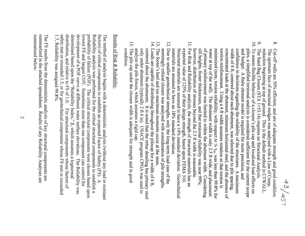
5 Chapter A-15 CID-MO Structural Analysis A-15.1 Overview This chapter addresses the structural features (floodwalls, gatewells, and closure structures) for the Missouri Central Industrial District (CID-MO) unit which includes existing conditions only because a raise is not being pursued at this time. The existing condition evaluation includes assigning reliability to the structures and recommending remedies if required. Elevations reference the NGVD29 datum as information was obtained from record drawings. For general structural methodology refer to the general structural chapter. A-15.2 Assumptions See the General Structural chapter for general KC Levees Structural Feasibility Assumptions. The following assumptions are in addition to those general assumptions, applying specifically to the CID Missouri Unit. 1. To assess flexible behavior of a closure s pile cap and localized load effects on piles, a simplified torsional analysis is considered sufficient for the current scope and budget. A finite element model is required for more precision, and confidence in decisions regarding the reliability of the structures. A maximum width of 4 ft, centered about each abutment, was selected due to pile spacing, concentrated loads at the abutment, minimum horizontal steel, and the absence of torsion reinforcement. Using a 4 ft width assumes rotation so that torsion is minimized (note, torsion reliability, with respect to ¼ τ cr, was less than 99.8% for water at top of the wall). The abutment width is only 2.5 ft wide, and placement of primary reinforcement was limited to within the abutment width. Considering sill heights, footer thicknesses, and that torsional reliability was near 99%; however, distribution of stresses beyond the 2.5 ft width is reasonable. 2. Due to smaller geotechnical strengths, only the long-term load case of the seemingly critical closure and floodwall was analyzed with consideration of pile strengths. 3. The footer s heel and toe maximum moments occur at the stem. 4. Loads are capable of distributing throughout the pilecap for a width of 4 ft, centered about the abutments. It is noted that the rebar detailing has primary steel only under abutment (typically 2 ft 6 in). USACE program CPGA was used to analyze the pile forces, which assumes a rigid cap. 5. The pile cap under the closure width is adequate for strength and in good condition. 6. For a consistent risk and economic comparison with other units T-wall results, axial tension in the heel of T-walls was not analyzed, shear and flexure in the floodwall keys were not analyzed, and shear friction at construction joints with only residual rebar capacity not used to resist bending was not checked. 7. Heels of T-walls were analyzed without contribution of key forces producing a pure moment into the heel. This moment is usually small in comparison with heel forces. Also, the heel was analyzed for net vertical pressures only. 1
6 Kansas Citys Levees Engineering Appendix Final Feasibility Report Chapter A Based on closure structure analysis, the following checks were not performed on the floodwalls because they proved not to control for the closures, therefore likely not control for the floodwalls: tension pile embedment, punching shear of pile through pilecap, vertical and horizontal bearing of pile and pile-cap, spread footer stability with shortterm strengths, horizontal shear in pile-cap (at sheetpile) and horizontal shear in all piles. 9. For a consistent risk and economic comparison of gate well stability calculations with other units results, a portion of soil skin friction is assumed aiding in the resistance of flotation. A crack is assumed in the top five feet of soil, which eliminates any contribution of the soil in resisting uplift. A-15.3 Soil Material Properties The expected soil properties used for the CID-MO calculations are located in Table A-15-1 These values were used for general soil properties in the structural calculations. The allowable bearing capacity values were used in the structural calculations and was arrived at by dividing the Ultimate Bearing Capacity from the table below by the factor of safety listed. Soil to structure friction and cohesion interaction was typically neglected for stability and strength calculations. However, for gatewells and spread footing founded floodwalls, this behavior was considered under geotechnical guidance. Friction Angle (drained shear strength) Embankment Fill/Debris Foundation Blanket Foundation Sand 29 o 20 o 22 o 30 o Cohesion Moist unit wt. 115pcf 110pcf 110pcf 115pcf Saturated unit wt. 120pcf 115pcf 115pcf 120pcf Wall friction coefficient (used in gatwell uplift) Ultimate Bearing Capacity compression (psf) FS=1.7 (Extreme Loading Condition) ,400 (Sta 0+00 to 7+00) 3,610 (Sta 7+00 to 7+50) 3,663 (Sta 7+50 to 10+25) 40,000 (Sta to 23+00) Table A-15-1: CID-MO Soil Properties 2
7 Kansas Citys Levees Engineering Appendix Final Feasibility Report Chapter A-15 A-15.4 CID-MO Existing Conditions A Floodwalls Existing Conditions Floodwalls on the CID-MO unit consist of spread footing floodwalls and pile founded floodwalls. For each of these types of walls the existing condition was evaluated. The evaluation entailed analysis of existing reliability and recommending solutions for any existing condition deficiencies. See the structural analysis appendix chapter for further information on reliability analysis. The existing CID-MO floodwalls are as follows: Sta to spread footing floodwall constructed in Sta to pile foundation floodwall constructed in This does not include walls that are part of a closure structure (see closure structures section). The floodwall is interrupted in locations where the wall ties into bridge piers or roadway ramp. The floodwall ties into existing ground at Sta and ties into an earthen levee at Sta The soil elevations both landside and riverside of the wall for the majority of the walls were field verified and where there were differences, the field noted elevations were used in the analysis. Clarification to pile details on the drawings - The record drawing (A ) shows only 18 square piles with and without tapers and the precast concrete sheet pile section. The last revision date on that sheet is 6/23/1947. Another drawing that apparently preceeded the record drawing shows 16 and 18 square piles without tapers and the precast concrete sheet pile section. All other drawings in the record drawings (as builts) show that there are 16 and 18 piles that were used including the driven pile lengths listed on record drawing A So the following assumptions were made for the feasibility analysis: piles not tapered and as detailed 2. All 18 piles tapered looking at 21 long pile (each type wall has at least 1 monolith with the 21 long piles) (therefore used 15 x15 dimensions for properties because of taper) 3. used the precast sheet pile as detailed on the record drawings The controlling probability of failure results for the spread footing walls is based on the controlling walls; 12ft wall for strength reliability (wall between Sta 0+00 to ) and Especial wall (wall between Sta and )for sliding reliability. The controlling probability of failure results for the pile footing walls is based on the wall R (wall between Sta to ) which controlled for pile geotechnical compression capacity. The pile capacities changed very little as the water level lowered down the wall, so the probability of failure analysis assumed the same pile capacity at each location. 3
8 Kansas Citys Levees Engineering Appendix Final Feasibility Report Chapter A-15 A Floodwall Existing Conditions Summary Station Wall Type CID-MO FLOODWALLS - Spread footing Floodwalls Existing Conditions with Water to Top of Wall OVERTURNING % Base in Compression (25% Req'd) BEARING (2.0 Req'd) Factors of Safety SLIDING (1.3 Req'd) STRENGTH Wall/ Heel/Toe (1.5 Req'd) to ' 72% to ' 83% to ' 100% to ' 95% to ' 68% to L (Monolith 29) 90% to M (Monolith 31) 100% to J (Monolith 34) 77% to H (Monolith 38) 80% to G (Monolith 40) 61% to F 33% to Fspecial 0% to Especial 0% to E (Monolith 47) 0% Mechanism Flexural Bottom Steel in Toe Flexural Bottom Steel in Toe Flexural Top Steel in Heel Flexural Top Steel in Heel Flexural Top Steel in Heel Flexural Bottom Steel in Toe Flexural Bottom Steel in Toe Flexural Bottom Steel in Toe Flexural Bottom Steel in Toe Flexural Bottom Steel in Toe Flexural Bottom Steel in Toe Flexural Riverside Steel in Stem Flexural Bottom Steel in Toe Flexural Bottom Steel in Toe Table A-15-2: CID-MO Existing Spread Footing Floodwall Conditions Comments 86% reliability for strength calculated 0% reliability for sliding CID-MO FLOODWALLS - Pile Foundation Floodwalls - Existing Conditions with Water to Top of Wall Factors of Safety Comments Concrete Sheet Piling Concrete Pile Wall Type STRENGTH Wall/ Pile Cap (1.5 Req'd) STRENGTH (1.5 Req'd) Geotech allowable Axial Compression and Tension loads (1.0 required) STRENGTH (1.5 Req'd) Geotech allowable Axial Compression and Tension loads (1.0 required) R tension compression Q tension compression Q-Monolith tension compression P tension compression N tension compression S tension Table A-15-3: CID-MO Existing Pile Footing Floodwall Conditions compression 96% reliability calculated for concrete pile geotechnical compression capacity 93% reliability calculated for heel strength 4
9 Kansas Citys Levees Engineering Appendix Final Feasibility Report Chapter A-15 A Floodwall Structures Remediation As a result of the findings noted in the floodwall existing conditions analysis, repair is recommended for approximately 292-feet of flood wall (between Sta and ). A preliminary recommended repair may be to: 1. reconstruct the heel key by demolishing the end of the heel at the existing unreinforced key 2. extending the heel key approximately 1-foot deeper than the existing key depth (total key depth of 2-feet) and reinforcing the key for E Special and F special walls 3. extending the heel approximately 2 feet riverward and constructing a new reinforced key approximately 4-feet. This repair will allow the key to be considered for sliding resistance for the stability of the floodwall. The 12-foot spread footing floodwall has a reliability of 69%. The analysis was based upon the maximum exposed stem height based upon field verified measurements. Much of the 12-foot wall has much less exposed stem since it is near the end of the protection where the groundline tapers up to the top of the wall (see record drawings). That coupled with a reasonably high reliability when water is to the top of the wall and the fact that once water is 1-foot down from the top of the wall, reliability is 98%, results in low risk of failure of the existing 12-foot spread footing floodwall. Similar results can be expected at the other walls with a low strength factor of safety. Some additional measures may be needed to address sliding in the area from Sta to 11+93, but they are expected to be minimal in nature. A Drainage Structures Existing Conditions The structural section of the Engineering Appendix for the Kansas City, Missouri and Kansas City, Kansas Flood Protection Project contains an evaluation of the existing gatewells abilities to meet Nominal 500 yr flood event. The three CID-MO gatewells and one manhole were analyzed with water to top of levee (worst case) only to determine their reliability for strength and flotation. The results of this analysis are shown in Table A The three gatewells and one manhole along the CID-MO unit were analyzed for flotation and strength requirements to determine if the gatewells could withstand water seepage pressures (HGL s) with water to top of flood walls. Results are summarized in Table A All values are based on the nominal 500 yr or water to top of levee (worst case). 5
10 Kansas Citys Levees Engineering Appendix Final Feasibility Report Chapter A-15 Station Flotation Factor of Safety (>1.1 Req'd) Existing Conditions with Water to Top of Protection HGL's From Geotech May 2011 Strength Factor of Safety (>1.5 Req'd) Controlling Structural Mechanism Assigned Reliability (%) Comment (GW) N/A 1.4 Wall Bending (MH) Base Slab Moment N/A Wall Bending N/A Base Slab Moment N/A N/A N/A N/A N/A The bottom of GW is the floodwall toe, therefore uplift is not analyzed. The floodwall stability is analyzed seperately. MH is 38.5' upstream of the gatewell, Line of Creep Method used for uplift pressures. HGL change. Gatewell is attached to Broadway pump station. Uplift not a concern. No Change from previous HGL estimate. Gatewell atatched to floodwall, uplift not a concern. Gatewell removed and rebuilt in Santa Fe Pump Station (Sheet #7, A ) Gatewell should be analyzed in unison with the Pump station. Table A-15-4: CID-MO Existing Gatewell Conditions Gatewell at Sta showed a 1.4 factor of safety for wall flexure, slightly less than the minimum requirement of 1.5. A probability of failure (POF) analysis was conducted which resulted in the wall being 99.86% reliable for strength. Flotation was not analyzed for this gatewell because the bottom of the gatewell is the toe of the floodwall. The floodwall stability was analyzed separately.. 6
11 Kansas Citys Levees Engineering Appendix Final Feasibility Report Chapter A-15 A Closure Structures Existing Conditions There were seven closure structures analyzed for the feasibility study: 1) M10 (STA ), 2) M18 (STA ), 3) M32 (STA ), 4) M145 (STA ), 5) M 158 (STA ), 6) M162 (STA ), and 7) a levee closure (STA ). The FS results from the deterministic analysis of key structural components are summarized in the table below. Pertaining to pile-founded closures (M145, M158, M162, and the Levee Closure), considering a simplified approach to qualify torsion, the geotechnical pullout strength of the tension piles (precast sheetpile) was critical. Reliability is 36% with water elevation at Tow of Wall (TOW); 85% with water elevation at 1 below TOW; and 99.5% with water elevation at 2 below TOW. With water elevation below 2 ft from TOW, the reliability is considered 99.8%. M145 was the most critical of all the pile-founded monoliths, and its results were used to establish POF plots vs water elevation for all closures. Since the closures were not found 99.8% reliable, without adjustment for structure degradation, a review in original design assumptions was performed. Like the present analysis, it seems that the original designers included water level to top of the wall. Unlike the present analysis, the original designers apparently only used undrained geotechnical strengths for the pile capacities (whereas the feasibility study included lower drained strengths), considered the closure s pile caps as rigid (whereas torsion was qualified in the feasibility study), but very conservatively ignored any efficiency of the cutoff wall to mitigate seepage and uplift pressures (whereas the cutoff wall efficiency was assumed 50% in the feasibility study). Setting aside remediation measures that may be borne out of the results from the feasibility analysis, the following recommendations are made in light of the site visit and analysis: 1. Most closures need maintenance at the abutments, including cleaning and painting embedded steel. 2. If possible, inspect pile caps for cracks and corrosion of rebar, and repair if necessary. 3. Inspect timber stop logs and repair/replace if needed. 4. Seal cracks and joints with appropriate sealant for exposed conditions and movement of concrete. 5. Should a finite element model, or other more detailed analysis, be performed, it is recommended that a 5% to 15% reduction in strength capacity be applied given the observations made during the site visit. Site visit observations can be found in the appendix with closure structure calculations. 7
12 Kansas Citys Levees Engineering Appendix Final Feasibility Report Chapter A-15 8
13 Kansas Citys Levees Engineering Appendix Final Feasibility Report Chapter A-15 A-15.5 RCBs and Pipes Associated with Gatewells There was no analysis done on the CID-MO pipes associated with the gatewells because there is no future conditions analysis (raise) for this unit. Existing pipes are assumed to be functioning at current state. Inspections and maintenance will be required for upkeep to system. The levee sponsor is responsible for maintaining all structures per the O&M (Operation and Maintenance) Manual. A-15.6 References: 1. CID-MO Plans for Construction of Broadway and Santa Fe Pumping Plants (October 1947) 2. Record Drawings; Appendix I Record Drawings; Operations and Maintenance Manual; Kansas Citys Flood Control Project; Missouri and Kansas Rivers; Central Industrial Unit Missouri Section; Sheet dates vary 3. Computations; Central Industrial District Mo. Section Design Computations, dated
14
15
16
17
18
19
20
21

22

23
24
25
26
27

28
Chapter A-14 CID-KS STRUCTURAL ANALYSIS
 Kansas Citys, Missouri and Kansas Flood Risk Management Study to the Final Feasibility Report Chapter A-14 CID-KS STRUCTURAL ANALYSIS Chapter A-14 CID-KS Structural Analysis Table of Contents A-14.1 Overview...
Chapter A-13 STRUCTURAL ANALYSIS ARGENTINE RAISE
 Kansas Citys, Missouri and Kansas Flood Damage Reduction Feasibility Study (Section 216 Review of Completed Civil Works Projects) Engineering Appendix to the Interim Feasibility Report Chapter A-13 STRUCTURAL
Chapter A-12 STRUCTURAL ANALYSIS EXISTING CONDITIONS
 Kansas Citys, Missouri and Kansas Flood Damage Reduction Feasibility Study (Section 216 Review of Completed Civil Works Projects) Engineering Appendix to the Interim Feasibility Report Chapter A-12 STRUCTURAL
Chapter A-8 GEOTECHNICAL ANALYSIS FAIRFAX-JERSEY CREEK (JERSEY CREEK SHEET PILE WALL)
") Kansas Citys, Missouri and Kansas Flood Damage Reduction Feasibility Study (Section 216 Review of Completed Civil Works Projects) Engineering Appendix to the Interim Feasibility Report Chapter A-8 GEOTECHNICAL
Kansas Citys, Missouri and Kansas Flood Damage Reduction Feasibility Study (Section 216 Review of Completed Civil Works Projects) Engineering Appendix to the Interim Feasibility Report Chapter A-8 GEOTECHNICAL
Appendix J: Structural Engineering
 Bass Ponds, Marsh, and Wetland Habitat Rehabilitation and Enhancement Project Feasibility Report and Integrated Environmental Assessment Upper Mississippi River Restoration Program January, 2019 TABLE
ENGINEERING REPORT STRUCTURAL STABILITY ANALYSIS FLOODWALLS. HOUSATONIC RIVER and NAUGATUCK RIVER FLOOD PROTECTION PROJECTS SECTION 1
 ENGINEERING REPORT STRUCTURAL STABILITY ANALYSIS FLOODWALLS HOUSATONIC RIVER and NAUGATUCK RIVER FLOOD PROTECTION PROJECTS SECTION 1 ANSONIA and DERBY, CONNECTICUT December 2010 MMI #1560-119 and #3118-03
twenty six concrete construction: foundation design ELEMENTS OF ARCHITECTURAL STRUCTURES: FORM, BEHAVIOR, AND DESIGN DR. ANNE NICHOLS SPRING 2013
 ELEMENTS OF ARCHITECTURAL STRUCTURES: FORM, BEHAVIOR, AND DESIGN DR. ANNE NICHOLS SPRING 2013 lecture twenty six concrete construction: www.tamu.edu foundation design Foundations 1 Foundation the engineered
Chapter A-9 GEOTECHNICAL ANALYSIS NORTH KANSAS CITY - LOWER (HARLEM AREA)
") Kansas Citys, Missouri and Kansas Flood Damage Reduction Feasibility Study (Section 216 Review of Completed Civil Works Projects) Engineering Appendix to the Interim Feasibility Report Chapter A-9 GEOTECHNICAL
Kansas Citys, Missouri and Kansas Flood Damage Reduction Feasibility Study (Section 216 Review of Completed Civil Works Projects) Engineering Appendix to the Interim Feasibility Report Chapter A-9 GEOTECHNICAL
twenty seven concrete construction: foundation design Foundation Structural vs. Foundation Design Structural vs. Foundation Design
 ARCHITECTURAL STRUCTURES: FORM, BEHAVIOR, AND DESIGN DR. ANNE NICHOLS SRING 2017 lecture twenty seven Foundation the engineered interface between the earth and the structure it supports that transmits
twenty four foundations and retaining walls Foundation Structural vs. Foundation Design Structural vs. Foundation Design
 ALIED ARCHITECTURAL STRUCTURES: STRUCTURAL ANALYSIS AND SYSTEMS DR. ANNE NICHOLS SRING 2018 lecture twenty four Foundation the engineered interface between the earth and the structure it supports that
Regulation 18 August 2009 NO Operations and Maintenance LEVEE ENCROACHMENT STANDARDS AND PROCEDURES
 CENWP-EC DEPARTMENT OF THE ARMY PDR 30-2-5 Portland District, Corps of Engineers (Draft) P.O. Box 2946 Portland, Oregon 97208 Regulation 8 August 2009 NO. 30-2-5 Operations and Maintenance LEVEE ENCROACHMENT
Chapter A-10 GEOTECHNICAL ANALYSIS NORTH KANSAS CITY - LOWER (NATIONAL STARCH AREA)
") Kansas Citys, Missouri and Kansas Flood Damage Reduction Feasibility Study (Section 216 Review of Completed Civil Works Projects) Engineering Appendix to the Interim Feasibility Report Chapter A-10 GEOTECHNICAL
Kansas Citys, Missouri and Kansas Flood Damage Reduction Feasibility Study (Section 216 Review of Completed Civil Works Projects) Engineering Appendix to the Interim Feasibility Report Chapter A-10 GEOTECHNICAL
Effective Stress Design For Floodwalls on Deep Foundations
 Effective Stress Design For Floodwalls on Deep Foundations Glen Bellew, PE Geotechnical Engineer USACE-Kansas City 23 April 2015 Contributors James Mehnert, PE USACE-Kansas City Paul Axtell, PE, D.GE Dan
16. Design of Pipeline Structures.
 16. Design of Pipeline Structures. a. General. 1) The following guidelines are for the design of structures for water and sewer pipelines including structural concrete and miscellaneous metals design.
INDIAN BEND WASH 2 LEVEE SYSTEM MARICOPA COUNTY, ARIZONA NLD SYSTEM ID #
 INDIAN BEND WASH 2 LEVEE SYSTEM MARICOPA COUNTY, ARIZONA NLD SYSTEM ID # 3805020008 PERIODIC INSPECTION REPORT NO. 1 GENERALIZED EXECUTIVE SUMMARY FINAL SYSTEM RATING: MINIMALLY ACCEPTABLE FINAL RATING
MILL CREEK LEVEE SYSTEM SAN BERNARDINO COUNTY, CALIFORNIA NLD SYSTEM ID #
 SAN BERNARDINO COUNTY, CALIFORNIA NLD SYSTEM ID # 3805010056 PERIODIC INSPECTION REPORT NO 1 GENERALIZED EXECUTIVE SUMMARY FINAL SYSTEM RATING: MINIMALLY ACCEPTABLE FINAL RATING DATE: SEPTEMBER 23, 2013
Modjeski and Masters, Inc. Consulting Engineers 04/18/06 St. Croix River Bridge 3D Analysis Report Introduction
 Introduction This memo presents a summary of a three dimensional (3D) analysis of the Organic concept for the proposed St. Croix River bridge project. The Organic concept has several attributes that are
Alexis Pacella Structural Option Dr. Schneider Lexington II, Washington D.C. Technical Report #3 November 21,
 1 Executive Summary: Lateral System Analysis and Confirmation Design is an depth look at the lateral system of Lexington II and the loads of which it must carry. The structural system of Lexington II is
Chapter 13: Retaining Walls
 Chapter 13: Retaining Walls Introduction In general, retaining walls can be divided into two major categories: (a) conventional retaining walls and (b) mechanically stabilized earth walls Conventional
UPPER MISSISSIPPI RIVER COMPREHENSIVE PLAN
 UPPER MISSISSIPPI RIVER COMPREHENSIVE PLAN APPENDIX D COST ESTIMATES Prepared by the U.S. Army Corps of Engineers Rock Island, St. Louis, and St. Paul Districts March 2008 UPPER MISSISSIPPI RIVER COMPREHENSIVE
Table of Contents 18.1 GENERAL Overview Responsibilities References
 Table of Contents Section Page 18.1 GENERAL... 18.1-1 18.1.1 Overview... 18.1-1 18.1.2 Responsibilities... 18.1-1 18.1.3 References... 18.1-2 18.2 MISCELLANEOUS FOUNDATION DESIGNS... 18.2-1 18.2.1 Buildings...
Chapter A-17 CONSTRUCTION PROCEDURES AND WATER CONTROL PLAN
 Kansas Citys, Missouri and Kansas Flood Damage Reduction Feasibility Study (Section 216 Review of Completed Civil Works Projects) Engineering Appendix to the Interim Feasibility Report Chapter A-17 CONSTRUCTION
(b) The written request must include 5 components: 1 The Permit Review and Approval Process. (1) Step 1: Pre-Coordination.
 The written request must include 5 components: 1 The Permit Review and Approval Process. (1) Step 1: Pre-Coordination.") 1 The Permit Review and Approval Process The processing of a Section 408 Permit request begins with a written request from an applicant. Along with the written request, a permit application (attached)
1 The Permit Review and Approval Process The processing of a Section 408 Permit request begins with a written request from an applicant. Along with the written request, a permit application (attached)
UPRR INDUSTRIAL LEAD BRIDGE T-WALL RETAINING WALL SYSTEM 5.0 x 7.5 UNITS DESIGN UNIT 018 WORK PACKAGE 04
 UPRR INDUSTRIAL LEAD BRIDGE T-WALL RETAINING WALL SYSTEM 5.0 x 7.5 UNITS DESIGN UNIT 018 WORK PACKAGE 04 1. Description This work shall consist of the design, manufacture and construction of a T-WALL structure
Section G1. Design of Cast-In-Place Box Conduits
 G1-1 Economy of Design 1. Height to Width Ratio Section G1 Design of Cast-In-Place Box Conduits Careful economic studies should be made to determine the greatest economy of the entire storm drain. As an
SAN GABRIEL RIVER 1 LEVEE SYSTEM LOS ANGELES COUNTY, CALIFORNIA NLD SYSTEM ID #
 LOS ANGELES COUNTY, CALIFORNIA NLD SYSTEM ID # 3805010031 PERIODIC INSPECTION REPORT NO. 2 GENERALIZED EXECUTIVE SUMMARY FINAL SYSTEM RATING: MINIMALLY ACCEPTABLE FINAL RATING DATE: APRIL 19, 2017 PERIODIC
Lecture Retaining Wall Week 12
 Lecture Retaining Wall Week 12 Retaining walls which provide lateral support to earth fill embankment or any other form of material which they retain them in vertical position. These walls are also usually
Cantilever or Restrained Retaining Wall Calculations
 Cantilever or Restrained Retaining Wall Calculations Organization: F.E.C. Project Name: Example Report Design by: LAA Job #: 9876 Date: 10/21/2013 Codes used: 2010 & 2013 CBC, 2009 & 2012 IBC, ACI 318-08
APPENDIX F VALUE ENGINEERING
 U.S. Army Corps of Engineers, Kansas City District Final Feasibility Report APPENDIX F VALUE ENGINEERING Kansas Citys, Missouri and Kansas Flood Risk Management Project Final Feasibility Report THIS PAGE
HURRICANE SANDY LIMITED REEVALUATION REPORT UNION BEACH, NEW JERSEY DRAFT ENGINEERING APPENDIX SUB APPENDIX B-2 FLOODWALL PILE ANALYSES EAST WALLS
 HURRICANE SANDY LIMITED REEVALUATION REPORT UNION BEACH, NEW JERSEY DRAFT ENGINEERING APPENDIX SUB APPENDIX B-2 FLOODWALL PILE ANALYSES EAST WALLS Revised March 2015 Preliminary Flood Wall Pile Analysis
CHAPTER 11: WALLS.
 CHAPTER 11: WALLS MODULAR BLOCK WALL (DRY CAST) Rather than being pre-approved as systems, the components of Modular block walls (dry cast) are pre-approved separately. The approved MBW components are
Foundation Design. π = pi ( radians or 180 ) ρ = reinforcement ratio in concrete beam design = A s /bd µ = coefficient of static friction
 ρ = reinforcement ratio in concrete beam design = A s /bd µ = coefficient of static friction") Foundation Design Notation: a = name for width dimension A = name for area b = width of retaining wall stem at base = width resisting shear stress b o = perimeter length for two-way shear in concrete footing
Foundation Design Notation: a = name for width dimension A = name for area b = width of retaining wall stem at base = width resisting shear stress b o = perimeter length for two-way shear in concrete footing
CHAPTER 23 PILES TABLE OF CONTENTS TABLE OF CONTENTS. 23.TOC Table of Contents... 30Jan Introduction... 30Jan2018
 CHAPTER 23 TABLE OF CONTENTS FILE NO. TITLE DATE TABLE OF CONTENTS 23.TOC Table of Contents... 30Jan2018 23.00 Introduction... 30Jan2018 DESIGN GUIDE FOR LATERALLY UNSUPPORTED 23.01-1 Notes and Definitions...
Water Control Structures Selected Design Guidelines Alberta Environment Page 13-1
 Alberta Environment Page 13-1 13.0 DROP INLET SPILLWAYS 13.1 General The drop inlet spillway is commonly used for providing flood protection for earth dams which have smaller reservoirs and/or smaller
Upon speaking with the representatives with Technical Foundations as well as Walder Foundations, it was determined that:
 As part of our analyses, we have considered the design and construction of the cantilever retaining wall that will be located along the north side of Lucks Lane, between Falling Creek and Gladstone Glen
MagnumStone Specifications Gravity
 MagnumStone Specifications Gravity SPECIFICATION FOR MAGNUMSTONE GRAVITY MECHANICALLY STABILIZED EARTH SYSTEM PART 1: GENERAL.01Description The work consists of supplying and installing all aspects of
1.364 ADVANCED GEOTECHNICAL ENGINEERING HOMEWORK No. 5
 .364 ADVANCED GEOTECHNICAL ENGINEERING HOMEWORK No. Due: Friday December 2. This question concerns the stability of an open slope cutting that will be used to provide construction access for a 3.2m deep
SANTA ANA RIVER/ SAN TIMOTEO CREEK 1 LEVEE SYSTEM SAN BERNARDINO COUNTY, CALIFORNIA NLD SYSTEM ID #
 SANTA ANA RIVER/ SAN TIMOTEO CREEK 1 LEVEE SYSTEM SAN BERNARDINO COUNTY, CALIFORNIA NLD SYSTEM ID # 3805030015 PERIODIC INSPECTION REPORT NO. 1 GENERALIZED EXECUTIVE SUMMARY FINAL SYSTEM RATING: UNACCEPTABLE
Design of Semi gravity Retaining Walls
 Design of Semi gravity Retaining Walls Example 13.1 A semi gravity retaining wall consisting of plain concrete (weight = 145 lb/ft³) is shown in Figure 13.9. The bank of supported earth is assumed to weigh
mortarless masonry Design Manual Part 1 (IS 456:2000) Section 1 Page 1 IS 456:2000 PLAIN AND REINFORCED CONCRETE - CODE OF PRACTICE
 Section 1 Page 1 IS 456:2000 PLAIN AND REINFORCED CONCRETE - CODE OF PRACTICE") SECTION 1. mortarless masonry Design Manual Part 1 (IS 456:2000) Section 1 Page 1 1.1 Overview of IS 456:2000 IS 456:2000 PLAIN AND REINFORCED CONCRETE - CODE OF PRACTICE IS 456:2000 is the current Indian
SECTION 1. mortarless masonry Design Manual Part 1 (IS 456:2000) Section 1 Page 1 1.1 Overview of IS 456:2000 IS 456:2000 PLAIN AND REINFORCED CONCRETE - CODE OF PRACTICE IS 456:2000 is the current Indian
Final Estimates Level 2
 Florida Department of TRANSPORTATION Final Estimates Level 2 Module 6: Structures 11/1/2017 FDOT Final Estimates Level 2 Release 11, Module 6 1 6-1 Module Content Concrete Structures Bridges Substructure
GEOTECHNICAL RESISTANCE FACTORS
 Chapter 9 GEOTECHNICAL RESISTANCE FACTORS Final SCDOT GEOTECHNICAL DESIGN MANUAL 9-i Table of Contents Section Page 9.1 Introduction... 9-1 9.2 Soil Properties... 9-2 9.3 Resistance Factors for LRFD Geotechnical
Advance Design of RC Structure Retaining Wall
 1 Retaining Wall Retaining Walls What are retaining walls Retaining walls are soil-structure systems intended to support earth backfills. Type of retaining walls Gravity retaining wall gravity walls rely
T-Wall Design Procedure (05 May 2008)
") 3.4.3.1 HPS T-Wall Design Procedure Description This design method evaluates the improvement in global stability by including the allowable shear and axial force contributions from the foundation piles
3.4.3.1 HPS T-Wall Design Procedure Description This design method evaluates the improvement in global stability by including the allowable shear and axial force contributions from the foundation piles
SCOPE OF WORK: for new structure for exterior elevator according to manufacturer requirement, with a 36ft tower to install new elevator for 2 floors
 5190 Indian Mound St Sarasota Fl. 34232 T 941 330-5095 F 941 866-2695 E-mail: jc generalcontractors@mac.com Web: http://jcontractor.com http://www.sarasotageneralcontractor.net Friday, June 24, 2016 The
THE FORENSIC MEDICAL CENTER
 THE FORENSIC MEDICAL CENTER Image courtesy of Gaudreau, Inc. TECHNICAL REPORT #1 OCTOBER 5, 2007 KEENAN YOHE STRUCTURAL OPTION DR. MEMARI FACULTY ADVISOR EXECUTIVE SUMMARY Image courtesy of Gaudreau, Inc.
BACKGROUND: SUBSURFACE CONDITIONS:
 2 BACKGROUND: The planned project consists of a prefabricated modular apartment building with underground parking, located on the site bounded by Dexter Avenue N. to the east, multi-story residential/commercial
SPECIFICATION FOR MAGNUMSTONE GEOGRID REINFORCED Mechanically Stabilized Earth (MSE) SYSTEM
 SYSTEM") MagnumStone Specifications Geogrid Reinforced SPECIFICATION FOR MAGNUMSTONE GEOGRID REINFORCED Mechanically Stabilized Earth (MSE) SYSTEM PART 1: GENERAL 1.01 Description The work consists of supplying
MagnumStone Specifications Geogrid Reinforced SPECIFICATION FOR MAGNUMSTONE GEOGRID REINFORCED Mechanically Stabilized Earth (MSE) SYSTEM PART 1: GENERAL 1.01 Description The work consists of supplying
Lake Houston Dam Comprehensive Evaluation of an Ambursen Dam
 Lake Houston Dam Comprehensive Evaluation of an Ambursen Dam ASDSO September 10, 2008 John Rutledge - Freese & Nichols, Inc. Chuck Easton - Freese & Nichols, Inc. Janis Murphy - Freese & Nichols, Inc.
Simplified Building Schematic for Typical Floor (Levels 9 through 22):
:") Introduction to Structural System Simplified Building Schematic for Typical Floor (Levels 9 through 22): Key: - Tower Columns - Tower Shear Walls - Parking Garage Columns - Parking Garage Shear Walls Solid
Introduction to Structural System Simplified Building Schematic for Typical Floor (Levels 9 through 22): Key: - Tower Columns - Tower Shear Walls - Parking Garage Columns - Parking Garage Shear Walls Solid
LOS ANGELES RIVER/ COMPTON CREEK 2 LEVEE SYSTEM LOS ANGELES COUNTY, CALIFORNIA NLD SYSTEM ID #
 LOS ANGELES RIVER/ COMPTON CREEK 2 LEVEE SYSTEM LOS ANGELES COUNTY, CALIFORNIA NLD SYSTEM ID # 3805010033 PERIODIC INSPECTION REPORT NO. 2 GENERALIZED EXECUTIVE SUMMARY FINAL SYSTEM RATING: UNACCEPTABLE
Chapter 2 Notation and Terminology
 Reorganized 318 Chapter Titles Chapter 1 General 1.1 Scope 1.2 Purpose 1.3 Interpretation 1.4 Drawings and Specifications 1.5 Testing and Inspection 1.6 Administatration and Enforcement 1.6.1 Retention
This document downloaded from vulcanhammer.net vulcanhammer.info Chet Aero Marine
 This document downloaded from vulcanhammer.net vulcanhammer.info Chet Aero Marine Don t forget to visit our companion site http://www.vulcanhammer.org Use subject to the terms and conditions of the respective
mortarless Design Manual Part 1 (AS 3600:2009) Section 1 Page 1 AS 3600:2009 PLAIN AND REINFORCED CONCRETE - CODE OF PRACTICE
 Section 1 Page 1 AS 3600:2009 PLAIN AND REINFORCED CONCRETE - CODE OF PRACTICE") SECTION 1. mortarless Design Manual Part 1 (AS 3600:2009) Section 1 Page 1 AS 3600:2009 PLAIN AND REINFORCED CONCRETE - CODE OF PRACTICE 1.1 Overview of AS 3600:2009 AS 3600:2009 is the latest Australian
SECTION 1. mortarless Design Manual Part 1 (AS 3600:2009) Section 1 Page 1 AS 3600:2009 PLAIN AND REINFORCED CONCRETE - CODE OF PRACTICE 1.1 Overview of AS 3600:2009 AS 3600:2009 is the latest Australian
UNIT-1 RETAINING WALLS
 UNIT-1 RETAINING WALLS PART-A 1. Describe about Retaining wall. 2. Define gravity retaining walls. BT-1 3. Classify the types of retaining walls. 4. Explain cantilever retaining wall? 5. Describe about
Pump Station Excavation
 Pump Station Excavation SPONSORED BY THE KIEWIT CORPORATION A capstone project for the The Department of Civil & Environmental Engineering in The Ira A. Fulton College of Engineering and Technology Brigham
SAN DIMAS WASH 7 LEVEE SYSTEM LOS ANGELES COUNTY, CALIFORNIA NLD SYSTEM ID #
 LOS ANGELES COUNTY, CALIFORNIA NLD SYSTEM ID # 3805010066 PERIODIC INSPECTION REPORT NO 1 GENERALIZED EXECUTIVE SUMMARY FINAL SYSTEM RATING: MINIMALLY ACCEPTABLE FINAL RATING DATE: FEBRUARY 27, 2015 PERIODIC
MSE WALLS CASE STUDIES. by John G. Delphia, P.E. TxDOT Bridge Division Geotechnical Branch
 MSE WALLS CASE STUDIES by John G. Delphia, P.E. TxDOT Bridge Division Geotechnical Branch COMMON RETAINING WALL TYPES CONCRETE BLOCK MSE TEMPORARY EARTH SPREAD FOOTING Gabions Drilled Shaft Soil Nail Tiedback
Footings GENERAL CONSIDERATIONS 15.2 LOADS AND REACTIONS 15.4 MOMENT IN FOOTINGS
 4 Footings GENERAL CONSIDERATIONS Provisions of Chapter 15 apply primarily for design of footings supporting a single column (isolated footings) and do not provide specific design provisions for footings
RetainingWalls. Professor of Geotechnical Engineering and Foundations. Faculty of Engineering - Cairo University. By Dr. Ashraf Kamal Hussein
 RetainingWalls By Dr. Ashraf Kamal Hussein Professor of Geotechnical Engineering and Foundations - 2012 1. Introduction Retaining wall: - a structure which retains from failure a soil mass or other materials
GEOTECHNICAL INVESTIGATION PROPOSED OUTFALL LOCATION CITY OF MORGAN S POINT DRAINAGE HARRIS COUNTY, TEXAS REPORT NO
 GEOTECHNICAL INVESTIGATION PROPOSED OUTFALL LOCATION CITY OF MORGAN S POINT DRAINAGE HARRIS COUNTY, TEXAS REPORT NO. 1140198001 Reported to: SIRRUS ENGINEERS, INC. Houston, Texas Submitted by: GEOTEST
APPLICATION FOR A BUILDING PERMIT (Retaining Wall/Garden Wall Construction Details)
") APPLICATION FOR A BUILDING PERMIT (Retaining Wall/Garden Wall Construction Details) City of San Jacinto 595 S. San Jacinto Ave San Jacinto CA 92583 951.487.7330 fax 951.654.9896 Must print legibly, submit
APPLICATION FOR A BUILDING PERMIT (Retaining Wall/Garden Wall Construction Details) City of San Jacinto 595 S. San Jacinto Ave San Jacinto CA 92583 951.487.7330 fax 951.654.9896 Must print legibly, submit
MAHALAKSHMI ENGINEERING COLLEGE TIRUCHIRAPALLI
 MAHALAKSHMI ENGINEERING COLLEGE TIRUCHIRAPALLI - 621213. QUESTION BANK WITH ANSWER DEPARTMENT: CIVIL SEMESTER: 07 SUBJECT CODE /NAME: CE 2401/DESIGN OF REINFORCED CONCRETE AND BRICK MASONDRY STRUCTURES
Earthquake Design of Flexible Soil Retaining Structures
 Earthquake Design of Flexible Soil Retaining Structures J.H. Wood John Wood Consulting, Lower Hutt 207 NZSEE Conference ABSTRACT: Many soil retaining wall structures are restrained from outward sliding
Foundation Strengthening Of Bascule Piers At The Bridge Of Lions
 Paper No. 22 Foundation Strengthening Of Bascule Piers At The Bridge Of Lions Structural Elements Jian Huang, Ph.D., P.E. G. Alan Klevens, P.E. Lichtenstein Consulting Engineers TENTH BIENNIAL SYMPOSIUM
CONSTRUCTION PLAN CHECKLIST
 CONSTRUCTION PLAN CHECKLIST The design engineer is responsible for ensuring that plans submitted for city review are in accordance with this checklist. It is requested that the executed checklist be submitted
DESIGNING AND CONSTRUCTION OF T-WALL RETAINING WALL SYSTEM
 Istanbul Bridge Conference August 11-13, 2014 Istanbul, Turkey DESIGNING AND CONSTRUCTION OF T-WALL RETAINING WALL SYSTEM T. C. NEEL and K.BOZKURT ABSTRACT This work shall consist of the design, manufacture
SAN DIMAS WASH 6 LEVEE SYSTEM LOS ANGELES COUNTY, CALIFORNIA NLD SYSTEM ID #
 LOS ANGELES COUNTY, CALIFORNIA NLD SYSTEM ID # 3805010067 PERIODIC INSPECTION REPORT NO 1 GENERALIZED EXECUTIVE SUMMARY FINAL SYSTEM RATING: MINIMALLY ACCEPTABLE FINAL RATING DATE: FEBRUARY 27, 2015 PERIODIC
TABLE OF CONTENTS. vii
 TABLE OF CONTENTS CHAPTER 1: INTRODUCTION...1 1.1 Scope...1 1.1.1 Screening...2 1.1.2 Detailed Evaluation...2 1.1.3 Retrofit Design Strategies...2 1.2 Design Earthquakes, Ground Motions, and Performance
DESIGN AND DETAILING OF RETAINING WALLS
 DESIGN AND DETAILING OF RETAINING WALLS (For class held from nd April 07) Dr. M. C. Nataraja, Professor, Civil Engineering Department, Sri Jayachamarajendra Collge of Engineering, Mysore-5a70 006 Phone:
See the IRC for additional information. See CPD-DS Information Bulletin 100 for Requirements for 1 & 2 Family Dwelling plan submittals.
 As a customer service initiative, the Kansas City, Missouri, City Planning and Development Department/Development Services, in cooperation with the Greater Kansas City Home Builders Association, has developed
ODOT Design & Construction Requirements for MSE Walls
 ODOT Design & Construction Requirements for MSE Walls Peter Narsavage, P.E. Foundation Engineering Coordinator Ohio Department of Transportation Office of Structural Engineering 2006 Ohio Transportation
Client Project Job # Wall Loc. SBWall Report deg 120 pcf 950 psf deg 0.0 ft. 6.0 ft 6.0 ft 2.0 ft. W16x50.
 SBWall Report Soils Data Soil Friction Angle, phi Soil Unit Weight, gamma Soil Surcharge (uniform), qs Passive Resistance, FSp Passive Wedge Width, PW*B Backfill Slope Angle, beta Ignore Passive Resistance,
VOLUNTARY - EARTHQUAKE HAZARD REDUCTION IN EXISTING HILLSIDE BUILDINGS (Division 94 Added by Ord. No. 171,258, Eff. 8/30/96.)
") DIVISION 94 VOLUNTARY - EARTHQUAKE HAZARD REDUCTION IN EXISTING HILLSIDE BUILDINGS (Division 94 Added by Ord. No. 171,258, Eff. 8/30/96.) SEC. 91.9401. PURPOSE. (Amended by Ord. No. 172,592, Eff. 6/28/99,
DIVISION 94 VOLUNTARY - EARTHQUAKE HAZARD REDUCTION IN EXISTING HILLSIDE BUILDINGS (Division 94 Added by Ord. No. 171,258, Eff. 8/30/96.) SEC. 91.9401. PURPOSE. (Amended by Ord. No. 172,592, Eff. 6/28/99,
UNION STATION EXPANSION AND RESTORATION
 UNION STATION EXPANSION AND RESTORATION WASHINGTON DC TECHNICAL REPORT III: LATERAL SYSTEM ANALYSIS Prepared By: Joseph W. Wilcher III Prepared For: M.K. Parfitt November 21, 2008 TABLE OF CONTENTS Addendum...
CALTRANS SDC PROCEDURE
 CALTRANS SDC PROCEDURE Robert Matthews H&N Infrastructure 3/7/2002 CALTRANS SDC PROCEDURE Slide No. 1 OVERVIEW APPLICABILITY OF SDC PRELIMINARY STRUCTURE SIZING LOCAL MEMBER DUCTILITY STAND-ALONE FRAME
OVERALL STRUCTURAL SYSTEM
 EXECUTIVE SUMMARY The at the Pittsburgh International Airport, PA, is a 275,000 square foot multi-use building located directly adjacent to the airport s landside terminal. The building consists of an
RISK ASSESSMENT FOR DAMS AND LEVEES
 RISK ASSESSMENT FOR DAMS AND LEVEES Nate Snorteland, P.E. Director, Risk Management Center Golden, CO 1 October 2011 US Army Corps of Engineers Outline Dams and Levees Decisions Screening Non-Routine Example
twenty two concrete construction: flat spanning systems, columns & frames ARCHITECTURAL STRUCTURES: FORM, BEHAVIOR, AND DESIGN
 ARCHITECTURAL STRUCTURES: FORM, BEHAVIOR, AND DESIGN DR. ANNE NICHOLS SUMMER 2014 lecture twenty two concrete construction: http:// nisee.berkeley.edu/godden flat spanning systems, columns & frames Concrete
AGUA FRIA RIVER 5 LEVEE SYSTEM MARICOPA COUNTY, ARIZONA NLD SYSTEM ID #
 AGUA FRIA RIVER 5 LEVEE SYSTEM MARICOPA COUNTY, ARIZONA NLD SYSTEM ID # 3805020001 PERIODIC INSPECTION REPORT NO. 1 GENERALIZED EXECUTIVE SUMMARY FINAL SYSTEM RATING: MINIMALLY ACCEPTABLE FINAL RATING
Route 360 Inverted T-beams. Carin Roberts-Wollmann Virginia Tech Tommy Cousins Clemson University Fatmir Menkulasi Louisiana Tech
 Route 360 Inverted T-beams Carin Roberts-Wollmann Virginia Tech Tommy Cousins Clemson University Fatmir Menkulasi Louisiana Tech Background Outline Scope and Objectives Development and Testing Topping
DESIGN OF RETAINING WALLS
 DESIGN OF RETAINING WALLS Dr. Izni Syahrizal bin Ibrahim Faculty of Civil Engineering Universiti Teknologi Malaysia Email: iznisyahrizal@utm.my Introduction Retaining wall is used to retain earth or other
Table of Contents. July
 Table of Contents 36.1 General... 3 36.1.1 Bridge or Culvert... 3 36.1.2 Box Culvert Size Restrictions... 4 36.1.3 Stage Construction for Box Culverts... 4 36.2 Dead Loads and Earth Pressure... 5 36.3
Attachment I-15: Reviews
 Attachment I-15: Reviews Attachment I-15 Agency Technical Review of Phase 2 and Phase 3 Documents January 2010 & August 2010 Attachment I-15, pg 1 ProjNet: Registered User Page 1 of 18 Comment Report:
Page 4-1 Hubbell Power Systems, Inc. All Rights Reserved Copyright 2014 LOAD DETERMINATION
 Page 4-1 Hubbell Power Systems, Inc. All Rights Reserved Copyright 2014 SECTION 4 CONTENTS STRUCTURAL LOADS... 4-4 PRELIMINARY TIEBACK DESIGN GUIDE... 4-5 PLACEMENT of TIEBACK ANCHORS... 4-7 TABLES for
SPECIFICATION FOR CORNERSTONE GEOGRID REINFORCED SEGMENTAL RETAINING WALL SYSTEM
 CornerStone Specifications Geogrid Reinforced SPECIFICATION FOR CORNERSTONE GEOGRID REINFORCED SEGMENTAL RETAINING WALL SYSTEM PART 1: GENERAL 1.01 Description The work consists of supplying and installing
Geotechnical Engineering Software GEO5
 Geotechnical Engineering Software GEO5 GEO5 software suite is designed to solve various geotechnical problems. The easy -to -use suite consists of individual programs with an unified and user-friendly
Xyston Inn. NY. Proposal. Xiaodong Jiang. Structure Option. Advisor: Dr. Linda Hanagan
 Proposal Xiaodong Jiang Structure Option Advisor: Dr. Linda Hanagan December 12, 2014 Executive Summary Xyston Inn is a 17-story hotel building that will be located in Brooklyn, New York. The design of
SEAU 5 th Annual Education Conference 1. ASCE Concrete Provisions. Concrete Provisions. Concrete Strengths. Robert Pekelnicky, PE, SE
 ASCE 41-13 Concrete Provisions Robert Pekelnicky, PE, SE Principal, Degenkolb Engineers Chair, ASCE 41 Committee* *The view expressed represent those of the author, not the standard s committee as a whole.
Simplified Building Schematic for Typical Floor (Levels 9 through 22):
:") Introduction to Structural System Simplified Building Schematic for Typical Floor (Levels 9 through 22): Key: - Tower Columns - Tower Shear Walls - Parking Garage Columns - Parking Garage Shear Walls Solid
Introduction to Structural System Simplified Building Schematic for Typical Floor (Levels 9 through 22): Key: - Tower Columns - Tower Shear Walls - Parking Garage Columns - Parking Garage Shear Walls Solid
HORROCKS. Engineering Review of Proposed Cast-in-Place. Reinforced Arch Culvert Specification. For. Rinker Material Concrete Pipe Division
 JO7 For Engineering Review of Proposed Cast-in-Place SPECS Item #6 December 12, 2018 Handout Date: December11, 201$ Prepared By: PLK Reviewed By: DAA HORROCKS PROJECT NO. 18001 Phase 27 Rinker Material
twenty two concrete construction: flat spanning systems, columns & frames Reinforced Concrete Design Reinforced Concrete Design
 ARCHITECTURAL STRUCTURES: FORM, BEHAVIOR, AND DESIGN DR. ANNE NICHOLS SUMMER 2013 lecture twenty two economical & common resist lateral loads concrete construction: flat spanning systems, columns & frames
SAN GABRIEL RIVER/SAN JOSE CREEK 1 LEVEE SYSTEM LOS ANGELES COUNTY, CALIFORNIA NLD SYSTEM ID #
 SAN GABRIEL RIVER/SAN JOSE CREEK 1 LEVEE SYSTEM LOS ANGELES COUNTY, CALIFORNIA NLD SYSTEM ID # 3805010052 PERIODIC INSPECTION REPORT NO 1 GENERALIZED EXECUTIVE SUMMARY FINAL SYSTEM RATING: MINIMALLY ACCEPTABLE
SAN GABRIEL RIVER/ COYOTE CREEK 2 LEVEE SYSTEM LOS ANGELES COUNTY, CALIFORNIA NLD SYSTEM ID #
 SAN GABRIEL RIVER/ COYOTE CREEK 2 LEVEE SYSTEM LOS ANGELES COUNTY, CALIFORNIA NLD SYSTEM ID # 3805010031 PERIODIC INSPECTION REPORT NO. 2 GENERALIZED EXECUTIVE SUMMARY FINAL SYSTEM RATING: MINIMALLY ACCEPTABLE
Limit Equilibrium Stability Analyses for Reinforced Slopes
 40 TRANSPORTATION RESEARCH RECORD 1330 Limit Equilibrium Stability Analyses for Reinforced Slopes STEPHEN G. WRIGHT AND J.M. DUNCAN Limit equilibrium slope stability analysis procedures have been successfully
Retaining Wall Design
 SIL 211 MEKANIKA TANAH Retaining Wall Design DR. IR. ERIZAL, MAGR DEPARTEMEN TEKNIK SIPIL DAN LINGKUNGAN FAKULTAS TEKNOLOGI PERTANIAN IPB 1 Conventional Retaining Walls Gravity Retaining Structures Stability
INDIAN BEND WASH 4 LEVEE SYSTEM MARICOPA COUNTY, ARIZONA NLD SYSTEM ID #
 INDIAN BEND WASH 4 LEVEE SYSTEM MARICOPA COUNTY, ARIZONA NLD SYSTEM ID # 3805020009 PERIODIC INSPECTION REPORT NO. 1 GENERALIZED EXECUTIVE SUMMARY FINAL SYSTEM RATING: MINIMALLY ACCEPTABLE FINAL RATING
Pile foundations Introduction
 Engineering manual No. 12 Updated: 06/2018 Pile foundations Introduction Program: Pile, Pile CPT, Pile Group The objective of this engineering manual is to explain the practical use of programs for the
In-plane testing of precast concrete wall panels with grouted sleeve
 In-plane testing of precast concrete wall panels with grouted sleeve P. Seifi, R.S. Henry & J.M. Ingham Department of Civil Engineering, University of Auckland, Auckland. 2017 NZSEE Conference ABSTRACT:
PAPERWORK REDUCTION ACT A. GENERAL
 U.S. DEPARTMENT OF HOMELAND SECURITY - FEDERAL EMERGENCY MANAGEMENT AGENCY RIVERINE STRUCTURES FORM O.M.B No. 1660-0016 Expires: 12/31/2010 PAPERWORK REDUCTION ACT Public reporting burden for this form