Hamilton Rapid Transit Preliminary Design and Feasibility Study
|
|
|
- Clara Strickland
- 6 years ago
- Views:
Transcription


1 Hamilton Rapid Transit Preliminary Design and Feasibility Study B-LINE STRUCTURAL ASSESSMENT DESIGN BRIEF Version:1.0
2 Hamilton Rapid Transit Preliminary Design and Feasibility Study B-LINE STRUCTURAL ASSESSMENT DESIGN BRIEF Version:1.0 November 2011
3 Table of Contents 1.0 INTRODUCTION PROPOSED RETAINING WALL ALONG NORTH SIDE OF PROPOSED LRT BRIDGE OVER HIGHWAY RECOMMENDATIONS PROPOSED RETAINING WALL ALONG SOUTH SIDE OF PROPOSED LRT BRIDGE OVER HIGHWAY EXISTING CP OVERPASS ON KING STREET WEST EAST OF DUNDURN STREET EXISTING CONDITION RECOMMENDATIONS EXISTING OVERHEAD PEDESTRIAN WALKWAY ACROSS KING STREET WEST AT SUMMERS LANE EXISTING CONDITION ACCOMMODATION OF THE LRT UNDER THE PEDESTRIAN BRIDGE RECOMMENDATIONS EXISTING VEHICULAR TUNNEL AT THE MCNAB TRANSIT TERMINAL EXISTING CONDITION RECOMMENDATIONS PROPOSED RETAINING WALL ALONG SOUTH SIDE OF QUEENSTON ROAD, WEST OF RED HILL VALLEY EXISTING CONDITION EVALUATED OPTIONS CONCLUSION DISCLAIMER File: November 4th 2011.doc 2011 SNC Lavalin Inc. All rights reserved i
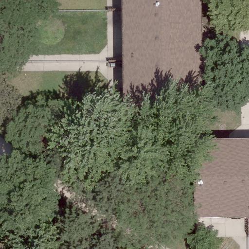
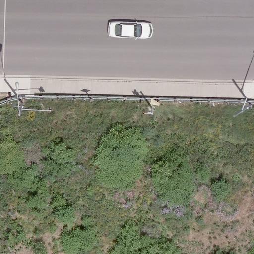
4 1.0 Introduction Through the preliminary design of the B-Line, it was determined that a structural assessment of seven structures along the alignment is needed to determine the extent of modifications, if any, that may be required to accommodate the LRT. These structures are the following: 1) A proposed retaining wall along the north side of the proposed LRT bridge over Highway 403 joining the west abutment (Station 2+000); 2) The proposed LRT bridge over Highway 403 (Station to Station 2+327); 3) A proposed retaining wall along the south side of the proposed LRT bridge over Highway 403 joining the east abutment (Station 2+332); 4) The existing CP overpass on King Street West east of Dundurn Street (Station 2+410); 5) The existing overhead pedestrian walkway across King Street West at Summer s Lane (Station 4+086); 6) The existing vehicular tunnel under King Street West at the McNab bus terminal (Station 4+189); 7) The existing Queenston Road bridge over the Red Hill Valley Parkway (Station to Station ) 8) A proposed retaining wall along south side of Queenston Road, west of Red Hill Valley (Station to Station ) The proposed bridge over Highway 403 (item 2) and the existing bridge over the Red Hill Valley Parkway (item 7) have undergone individual structural assessments under separate covers and will not be included in the assessment herein. 2.0 Proposed retaining wall along north side of proposed LRT bridge over Highway 403 The proposed bridge over Highway 403 is south of a parking lot which is susceptible to spill of the fill from under the LRT bridge. The purpose of the retaining wall is to contain the fill under the guideway as well as protect one existing mature tree (See Figures 1 and 2). The retaining wall will be approximately 35 m long and the height will vary between 4 m and 1.5 m. The construction cost of the retaining wall will be approximately $ 175,000, which could be substantially reduced if the fill is allowed to spill on to the existing parking lot, resulting in a loss of some parking spaces. In order to help balance the impact, the parking lot may be expanded to the southwest to compensate for the lost spaces. 2.1 Recommendations It is recommended that the feasibility of reconfiguring the parking lot in order to avoid the construction of a full retaining wall and avoid any potential impacts on the mature tree be assessed by the City of Hamilton in the next design stage. If reconfiguring the parking lot is not feasible and a retaining wall must be installed, further detailed design of the retaining wall in order to protect the mature tree must be undertaken in the next design phase. This can be accompanied by a cost benefit analysis of both options prior to the detailed design phase. File: November 4th 2011.doc 2011 SNC Lavalin Inc. All rights reserved 2
5
6
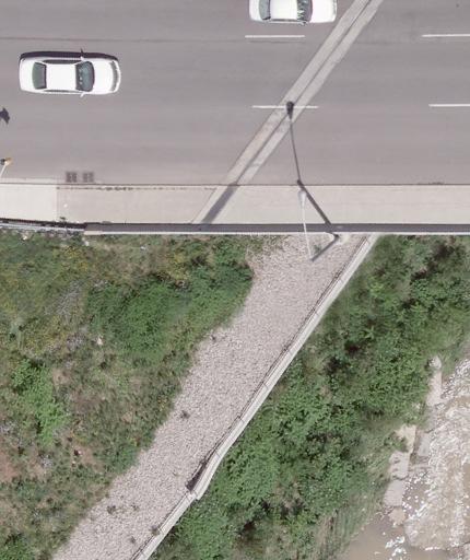
7 3.0 Proposed retaining wall along south side of proposed LRT bridge over Highway 403 The proposed wing wall of the bridge abutment will be an extended wing wall from the LRT bridge abutment (See Figures 3 and 4). It is needed to protect the existing asphalt path along the valley and to protect some mature trees to the south. The retaining wall will be approximately be 12 m long and will vary in height between 4.5 m and 1.5 m. The construction cost of the retaining wall will approximately be $ 95,000. File: November 4th 2011.doc 2011 SNC Lavalin Inc. All rights reserved 5

8
9 King Street West Figure 4: Proposed South Retaining Wall at East Side of Proposed LRT Bridge over Highway Cross-Section
10 4.0 Existing CP overpass on King Street West east of Dundurn Street 4.1 Existing Condition The existing overpass structure consists of steel I-beam girders spanning over two CP rail tracks with an opening of 9 m. The total width of the overpass is approximately 27.5 m, which includes two 1.8 m sidewalks and a 23.8 m roadway. Twelve steel girders with a height of 960 mm support the reinforced concrete slab with a distance from centre to centre of 2.3 m. The combined thickness of the concrete slab and asphalt pavement is 1200 mm (See Figure 5). 4.2 Recommendations The guideway will occupy 8 m of the overpass, occupying two traffic lanes on the south side (See Figure 6). The structural assessment confirmed that the existing structure with five girders directly under the guideway was sufficient to carry the additional load of the guideway and the LRT vehicles. The rails will be fixed to the existing reinforced concrete slab and an additional concrete pour will embed the grooved rails. Although the thickness of the reinforced slab is not known at this preliminary assessment phase, it will need to be determined in the detailed design phase in order to define the design detail of the rail fixation to the slab. If possible, the guideway should be flushed with the pavement. If a height difference must be tolerated, the guideway should become level with the pavement within the available 20 m before the next side entrance to the south. File: November 4th 2011.doc 2011 SNC Lavalin Inc. All rights reserved 8

11 Figure 5: CP Overpass east of King and Dundurn File: November 4th 2011.doc 2011 SNC Lavalin Inc. All rights reserved 9
12 Figure 6: Plan and Profile of the Guideway across the CP overpass File: November 4th 2011.doc 2011 SNC Lavalin Inc. All rights reserved 10
13 5.0 Existing overhead pedestrian walkway across King Street West at Summers Lane 5.1 Existing Condition There is an enclosed steel walkway over King Street West at Summers Lane, between Bay and McNab Street (See Figures 7 and 8). The walkway spans the entire length of the street, which is 26 m and has a width of 6 m. The clearance under the walkway is only 4.2 m, which is considered substandard. There have been recorded incidents of tractor-trailers scraping the underside of the bridge. With the addition of the LRT, this becomes an even greater concern as the clearance will be further diminished due to the addition of a catenary contact wire attachment to the underside of the bridge. Damage to the supports of the contact wire may cause short circuiting between the 750 V live wires and the steel structure, possibly endangering pedestrians both on the walkway and on the sidewalks. 5.2 Accommodation of the LRT under the pedestrian bridge The LRT contact wires can be affixed to the underside of the walkway either using a cross I-beam and clamps or by using a steady arm (See Figure 9). The minimum operating height of the pantograph is approximately 4 m, leaving only 200 mm for clearance. While it is possible to accommodate the LRT under the existing bridge, and this condition can be further examined in the detailed design phase, the City of Hamilton must carefully review the risk of truck impacts to the underside of the walkway resulting in possible damage to the contact wire supports. 5.3 Recommendations Due to the possible safety risk as a result of substandard clearance under the walkway, it is recommended that the City of Hamilton assess the feasibility of removing the bridge prior to the construction of the B-Line. The City should consult with the relevant stakeholders, particularly the Convention Centre and the Sheraton Hotel, as well as study the usage of the walkway. If the walkway is deemed necessary, the feasibility of raising the pedestrian bridge to comply with the recommended clearance of 5.3m to the underside of the bridge should be investigated. The raised walkway can be partially accommodated by ramps/stairs which can be constructed over the sidewalks on either side of the bridge. A safe attachment of contact wires to the underside with sufficient insulation should be included in the redesign for the reconfiguration of the raised structure. File: November 4th 2011.doc 2011 SNC Lavalin Inc. All rights reserved 11

14 Figure 7: Pedestrian Walkway over King St West between McNab and Bay St. File: November 4th 2011.doc 2011 SNC Lavalin Inc. All rights reserved 12
15 Figure 8: Plan and Profile of Pedestrian Walkway over King Street File: November 4th 2011.doc 2011 SNC Lavalin Inc. All rights reserved 13
16 Figure 9: Detail of possible attachment of contact wire to Pedestrian Walkway underside using I-beams and clamps File: November 4th 2011.doc 2011 SNC Lavalin Inc. All rights reserved 14
17 6.0 Existing Vehicular Tunnel at The McNab Transit Terminal 6.1 Existing Condition The tunnel is located under King Street West along McNab Street and links two vehicular lanes with the underground access to the McNab Transit Terminal. The tunnel has a total width of 8.5 m and has a vertical clearance of 4.4 m (See Figures 10 and 11). The minimum burden thickness is 1.14 m. The LRT profile along King Street West is shown in Figure Recommendations The structural assessment confirmed that the tunnel structure can accommodate the additional loads from the guideway and the LRT vehicles. The 1.14 m burden thickness allows for the guideway to be flushed without any structural constraints (See Figures 13 and 14). It is recommended to apply floating trackwork structures across the tunnel to avoid transfer of vibration to the tunnel roof and to the adjacent buildings. Special measures to avoid damage to the tunnel cover slab during construction and to maintain the current level of waterproofing to the tunnel need to be developed in the detailed design phase. File: November 4th 2011.doc 2011 SNC Lavalin Inc. All rights reserved 15

18 Figure 10: Vehicular tunnel under King Street at McNab Transit Terminal File: November 4th 2011.doc 2011 SNC Lavalin Inc. All rights reserved 16
19 Figure 11: Plan view of Vehicular Tunnel under King Street File: November 4th 2011.doc 2011 SNC Lavalin Inc. All rights reserved 17
20 Figure 12: Profile of LRT guideway over existing Vehicular Tunnel under King Street File: November 4th 2011.doc 2011 SNC Lavalin Inc. All rights reserved 18
21
22
23 7.0 Proposed retaining wall along south side of Queenston Road, West of Red Hill Valley 7.1 Existing Condition In the section between Station E to Station E near the Red Hill Valley Bridge, the road alignment as a negative slope to the east towards the bridge. Currently there are retaining walls on the north side adjacent to an apartment building and on the south side towards the Red Hill Valley Bridge. The introduction of the B-Line LRT requires road widening. Therefore, it is necessary to implement a retaining wall structure on the south side, just west of Station E Below are three options evaluated for the new retaining wall, along with a recommendation of the preferred option. 7.2 Evaluated Options The structural assessment of the adjoining area confirmed that a new retaining wall should be constructed just west of the existing retaining wall on the south side, and will have an approximate length of 68 m. Three options were evaluated for the type of retaining wall construction: Option A - A cantilever wall that is reverse T-shaped; Option B A cantilever wall that is L shaped; Options C A wall that is fixed using soil nails. Option A: Option A is a reverse T-shaped cantilever wall as shown in the figure below. The wall will have a maximum height of 2.7 m and a maximum width of footing will be 3.2m. The wall thickness will be 0.4m. The advantage of this option is that it uses less concrete and rebar than Option B. The disadvantage of this option is that it will require more backfill compared to Option B, as well as it requires excavation near the property line, although it is not expected that the construction of the retaining wall will compromise the structural integrity of the building, as it is assumed the dwelling has a basement. The impacts to property can be minimized if adequate construction staging methods are developed during the detail design phase. As the footing only extends slightly towards the guideway, there is still adequate room for the construction of a catch basin. File: November 4th 2011.doc 2011 SNC Lavalin Inc. All rights reserved 21
24 Figure 13: Option A Cantilever reverse T-shaped Retaining Wall Option B: Option B is an L-shaped cantilever wall as shown in the figure below. The maximum height of the wall measures 2.7 m. The maximum footing width is 3.6m, with a constant wall thickness of 0.4m. The advantage of this option is that it requires less excavation towards the property line than Option A. The disadvantage of this option is that it requires more concrete and rebar than Option A. Also, the footing extends towards the road which implies that more road construction would be required in comparison to the other two options. Additionally, the proximity of the footing to the road surface near the curb locations could negatively impact the placement of required catch basins and leads. Figure 14: Option B Cantilever L-shaped Retaining Wall File: November 4th 2011.doc 2011 SNC Lavalin Inc. All rights reserved 22
25 Option C: Option C is a retaining wall that is fixed using stabilizing soil nails. The advantage of this option is that it is the most economical option in terms of concrete and rebar quantities. The disadvantage is the nails encroach on to the property, which may require property acquisition, potentially resulting in an additional cost. Figure 15: Option C Retaining Wall fixed with Soil Nails 7.3 Conclusion Based on the above listed advantages and disadvantages of the three options, it has been determined that Option A should be further evaluated in the detailed design phase. A plan view of the proposed option A is shown in Figure 16 below. File: November 4th 2011.doc 2011 SNC Lavalin Inc. All rights reserved 23


26 Figure 16: Plan View of Proposed Retaining Wall - Option A
27 Disclaimer This document contains the expression of the professional opinion of Steer Davies Gleave North America Inc. ( SDG ) as to the matters set out herein, using its professional judgment and reasonable care. It is to be read in the context of the agreement (the Agreement ) between SDG and the City of Hamilton (the Client ) for the Rapid Transit Preliminary Design and Feasibility Study (reference C ), and the methodology, procedures and techniques used, SDG s assumptions, and the circumstances and constrains under which its mandate was performed. This document is written solely for the purpose stated in the Agreement, and for the sole and exclusive benefit of the Client, whose remedies are limited to those set out in the Agreement. This document is meant to be read as a whole, and sections or parts thereof should thus not be read or relied upon out of context. SDG has, in preparing the Agreement outputs, followed methodology and procedures, and exercised due care consistent with the intended level of accuracy, using its professional judgment and reasonable care. However, no warranty should be implied as to the accuracy of the Agreement outputs, forecasts and estimates. This analysis is based on data supplied by the client/collected by third parties. This has been checked whenever possible, however SDG cannot guarantee the accuracy of such data and does not take responsibility for estimates in so far as they are based on such data. SDG disclaims any liability to the Client and to third parties in respect of the publication, reference, quoting, or distribution of this report or any of its contents to and reliance thereon by any third party. DOCUMENT END File: November 4th 2011.doc 2011 SNC Lavalin Inc. All rights reserved 24
DESIGN OF TEMPLETON OVERPASS FOR THE CANADA LINE. Yulin Gao, M.A.Sc., P.Eng., SNC-Lavalin Inc. Samson Chan, M.Eng.,P.Eng., SNC-Lavain Inc.
 DESIGN OF TEMPLETON OVERPASS FOR THE CANADA LINE Yulin Gao, M.A.Sc., P.Eng., SNC-Lavalin Inc. Samson Chan, M.Eng.,P.Eng., SNC-Lavain Inc. Roger Woodhead, PhD, P.Eng., SNC-Lavain Inc. Paper prepared for
3.6 Construction Methods
 Exhibit 144: Birchmount Stop Layout West Don River Bridge - Girders are adequate to accommodate LRT right-of-way and required deck widening. Supplementary support or deck strengthening may be required
DESIGN OF CAMPBELL ROAD OVERPASS IN KELOWNA. Yulin Gao, M.A.Sc., P.Eng., SNC-Lavalin Inc. Samson Chan, M.Eng., P. Eng., SNC-Lavalin Inc.
 DESIGN OF CAMPBELL ROAD OVERPASS IN KELOWNA Yulin Gao, M.A.Sc., P.Eng., SNC-Lavalin Inc. Samson Chan, M.Eng., P. Eng., SNC-Lavalin Inc. Paper prepared for presentation at the Bridges in a Climate of Change
Chapter 1. General Design Information. Section 1.02 Structure Selection and Geometry. Introduction
 Chapter 1 Bridge Design Manual General Design Information Section 1.02 Selection and Geometry Introduction Selection or Rehabilitation Report This section of the design manual provides guidance on the
Conceptual Design Report
 Conceptual Design Report I-244/Arkansas River Multimodal Bridge Tulsa, Oklahoma Prepared for the Oklahoma Department of Transportation Prepared by: August 2009 I-244 / ARKANSAS RIVER MULTIMODAL BRIDGE
Structural - Engineering Review Checklist
 Structural - Engineering Review Checklist Project: List Corridor Criteria ID Review Priority (H,M,L) TOPICS S-_-## Structural Design Codes, Manuals and Specifications 6.1.0 REFERENCES DESIRED Criteria
Review of Plans and Specs from a Constructability Perspective
 Review of Plans and Specs from a Constructability Perspective The Executive Regional Manager and the Project Manager, with approval of the Director of Project Management, may request the Constructability
APPENDIX D STRUCTURAL REPORT
 Toronto Transit Commission / City of Toronto SCARBOROUGH-MALVERN LIGHT RAIL TRANSIT TRANSIT PROJECT ASSESSMENT STUDY ENVIRONMENTAL PROJECT REPORT APPENDICES APPENDIX D STRUCTURAL REPORT IBI Group Scarborough
Landscaping and Fencing
 Landscaping and Fencing Fences, driveways, paving, retaining walls, landscaping & other garden features To be read in conjunction with General Requirements: A guide to building on properties containing
Canadian Consulting Engineering Awards 2016 CANADIAN NIAGARA POWER FOREBAY BRIDGE RECONSTRUCTION
 Canadian Consulting Engineering Awards 2016 CANADIAN NIAGARA POWER FOREBAY BRIDGE RECONSTRUCTION April 2016 ELLIS Engineering Inc. 214 Martindale Road, Suite 201 St. Catharines, Ontario L2S 0B2 www.ellis.on.ca
ITEM 6 CONCRETE CURBS, GUTTERS, AND SIDEWALKS
 ITEM 6 CONCRETE CURBS, GUTTERS, AND SIDEWALKS 6.1 DESCRIPTION This work shall consist of constructing curbs, gutters, sidewalks, ramps, local depressions and driveways of the form and dimensions shown
Chapter 4 Bridge Program Drawings
 Chapter 4 Bridge Program Drawings Section 4.10-Bridge Railing Introduction Steel bridge railing and concrete bridge barrier rail are installed along the edge of the bridge roadway to keep errant vehicles
SECTION CONCRETE PAVING
 PART 1 GENERAL 1.1 SECTION INCLUDES SECTION 32 13 13 CONCRETE PAVING A. Extent of concrete curbs, walks, and paving as show on drawings B. Earthwork and prepared sub-base C. Concrete and related materials
Installation Guidelines
 815 NE 172 nd Avenue Vancouver, WA 98684 877-694-0141 Installation Guidelines Installation steps include job planning, layout, excavating and preparing the soil subgrade, applying geotextiles (optional),
DIVISION 6. ACCESSORY USES OR STRUCTURES
 DIVISION 6. ACCESSORY USES OR STRUCTURES Sec. 58-591. Generally. (a) Principal use or structure required to be present. An accessory use or structure in any zoning district shall not be established prior
SECTION CS-2. TRENCH EXCAVATION CONSTRUCTION STANDARDS
 SECTION CS-2. TRENCH EXCAVATION CONSTRUCTION STANDARDS CS-2-01. GENERAL: Trench excavation shall conform with the City Standard Specifications. In general a trench is defined as an excavation in which
New Jersey Turnpike Authority
 New Jersey Turnpike Authority DOCUMENT UPDATE REQUEST Forward to Assistant Chief Engineer, Design Initiator Russell Saputo, PE Submittal Date 6/21/16 Firm Stantec Consulting Services Inc. Telephone 201-587-9040
CONSTRUCTION SPECIFICATION FOR SITE RESTORATION FOLLOWING INSTALLATION OF PIPELINES, UTILITIES, AND ASSOCIATED STRUCTURES
 ONTARIO PROVINCIAL STANDARD SPECIFICATION METRIC OPSS 492 NOVEMBER 2010 CONSTRUCTION SPECIFICATION FOR SITE RESTORATION FOLLOWING INSTALLATION OF PIPELINES, UTILITIES, AND ASSOCIATED STRUCTURES TABLE OF
CHAPTER 13 R-5 MANUFACTURED MOBILE HOME PARK RESIDENTIAL DISTRICT
 15.1300 CHAPTER 13 R-5 MANUFACTURED MOBILE HOME PARK RESIDENTIAL DISTRICT 15.1301 SECTION 13.01 STATEMENT OF PURPOSE To provide for manufactured home park development, of long-term duration of stay, in
SAFEGUARDS DURING CONSTRUCTION
 CHAPTER 14 SAFEGUARDS DURING CONSTRUCTION SECTION 1401 GENERAL [B] 1401.1 Scope. The provisions of this chapter shall govern safety during construction that is under the jurisdiction of this code and the
MINNESOTA HISTORIC PROPERTY RECORD PART I. PROPERTY IDENTIFICATION AND GENERAL INFORMATION
 MINNESOTA HISTORIC PROPERTY RECORD PART I. PROPERTY IDENTIFICATION AND GENERAL INFORMATION Common Name: Camp Ripley Bridge Bridge Number: 4969 Identification Number: Location: Feature Carried: TH 115 Feature
It must be lowered 5 feet (1.5 meters) onto the bearings. Waterway clearance is decreased.
 onto the bearings. Waterway clearance is decreased.") CHAPTER 12 DECK-TYPE BRIDGES Deck-type panel bridges are normally twolane, class 50 or higher bridges assembled to replace single-lane bridges. A deck-type panel bridge has the following advantages over
CHAPTER 12 DECK-TYPE BRIDGES Deck-type panel bridges are normally twolane, class 50 or higher bridges assembled to replace single-lane bridges. A deck-type panel bridge has the following advantages over
CITY COUNCIL AGENDA Workshop Meeting: Tuesday, October 24, 2017
 1 2 CITY COUNCIL AGENDA Workshop Meeting: Tuesday, October 24, 2017 AGENDA ITEM: 2 Hear and deliberate on handrail, lighting, and walkway replacement options for Key Allegro Bridge on Bayshore Drive. SUBMITTED
ATTACHMENT F EXAMPLE SIMPLE CONCEPTUAL CTD (CONTRACT TIME DETERMINATION) FOR 25% DESIGN STAGE
 FOR 25% DESIGN STAGE") ATTACHMENT F EXAMPLE SIMPLE CONCEPTUAL CTD (CONTRACT TIME DETERMINATION) FOR 25% DESIGN STAGE DEVELOPED FOR CONSTRUCTION PLANNING DURING THE DESIGN PHASE REV2 10JAN14 CONTENT ATTACHMENT F SIMPLE/CONCEPTUAL
ATTACHMENT F EXAMPLE SIMPLE CONCEPTUAL CTD (CONTRACT TIME DETERMINATION) FOR 25% DESIGN STAGE DEVELOPED FOR CONSTRUCTION PLANNING DURING THE DESIGN PHASE REV2 10JAN14 CONTENT ATTACHMENT F SIMPLE/CONCEPTUAL
Historic Bridge Foundation Facebook Archives
 Historic Bridge Foundation Facebook Archives Focus Bridge: Adamsville Bridge April 2016 The Adamsville Bridge is one of the most unique historic bridges in America. It is a reinforced concrete cantilever
Bridge Barrier Development Presentation to the MFLNRO April John Deenihan Ph.D., EIT Julien Henley M.A.Sc., P.Eng
 Bridge Barrier Development Presentation to the MFLNRO April 2014 John Deenihan Ph.D., EIT Julien Henley M.A.Sc., P.Eng Contents Introduction Contents Introduction Background Information / Synopsis Contents
SCCRTC- MP San Lorenzo River Bridge Walkway Widening Feasibility Report
 SCCRTC- MP 19.43 San Lorenzo River Bridge Walkway Widening Feasibility Report May 19, 2016 INTRODUCTION Jacobs Engineering Group was selected to provide a feasibility report for the Santa Cruz County Regional
Second Avenue Subway
 Second Avenue Subway Community Board 8 Second Avenue Subway Task Force Update January 22, 2015 Tom Peyton Second Avenue Subway Project Director 0 Scope: Q train service Tunnels from 92nd St to 63rd St
CITY OF WINDSOR STANDARD SPECIFICATIONS JULY 2012 S-31 KEYHOLE EXCAVATION TABLE OF CONTENTS
 TABLE OF CONTENTS 31.01. SCOPE OF WORK... 1 31.02. REFERENCES... 1 31.03. DEFENITIONS... 1 31.04. MATERIALS... 2 31.05. EQUIPMENT... 3 31.06. CONSTRUCTION... 4 31.07. QUALITY ASSURANCE... 6 31.08. MEASUREMENT
SUBDIVISION SECTION STREET DESIGN MANUAL
 CITY OF ANAHEIM SUBDIVISION SECTION STREET DESIGN MANUAL A. INTRODUCTION : POLICY STATEMENT B. STREET CLASSIFICATION C. STREET STANDARDS REQUIREMENTS Requirements Approval of Street Improvement Plans Widening
EXCAVATION WORK IN PUBLIC RIGHT-OF-WAY GENERAL NOTES
 CITY OF SANTA MONICA Department of Public Works Civil Engineering Division 1685 Main, Room 116 Santa Monica, CA 90401 Tel: (310) 458-2240 or (310) 458-8737 EXCAVATION WORK IN PUBLIC RIGHT-OF-WAY GENERAL
Section 13. Guidelines for the Design of Ground Mounted Sign Supports
 Section 13 BDC11MR-04 13.1 Introduction Highway signs fall into two main categories, which are subdivided as follows: 1. Overhead Signs a. Sign Bridge Structures (GO) b. Sign Cantilever Structures (GO)
Eglinton Crosstown LRT Construction Liaison Committee
 Eglinton Crosstown LRT Construction Liaison Committee May 30, 2017 Agenda Eglinton Crosstown LRT Overview Eglinton Maintenance & Storage Facility Mount Dennis Station Railway Corridor West Portal & Elevated
CHAPTER 3 SCOPE SUMMARY
 CHAPTER 3 SCOPE SUMMARY GENERAL The SDDOT is an active member of AASHTO to share common national design standards for the state highway system. The AASHTO Task Force on Geometric Design has completed the
- DEFINITIONS (Defined Terms)
") A - DEFINITIONS (Defined Terms) A/E means Architect and Engineer. Abutting means to border upon. Access easement means an easement created for the purpose of providing vehicular or pedestrian access. ADA
A - DEFINITIONS (Defined Terms) A/E means Architect and Engineer. Abutting means to border upon. Access easement means an easement created for the purpose of providing vehicular or pedestrian access. ADA
The Most Advanced Name in Water Management Solutions TM. The most cost-effective slotted and trench surface drain systems.
 The Most Advanced Name in Water Management Solutions TM The most cost-effective slotted and trench surface drain systems. A sensible alternative to metal and concrete Since 1987, Duraslot surface drains
Chapter 3: Permit Procedures and Requirements
 Chapter 1: General Provisions 1 1 Short Title 1 2 Jurisdiction 1 3 Amendments and Revisions 1 4 Enforcement Responsibility 1 5 Review Process 1 6 Prior Approval 1 7 Relationship to Other Standards 1 8
APPLICANT any person who makes application for a permit. BOROUGH Borough of Elizabethtown, Lancaster County, Pennsylvania.
 CHAPTER 21 PART 2 TUNNELING AND EXCAVATIONS 201. Definitions. The following words and phrases, when used in this Part, shall have the meanings ascribed to them in this 201, except in those instances where
SPECIFICATIONS FOR STREET CONSTRUCTION WITHIN THE TOWN OF PLAINVILLE
 SPECIFICATIONS FOR STREET CONSTRUCTION WITHIN THE TOWN OF PLAINVILLE BE IT ORDAINED by the Town Council of the Town of Plainville: SECTION 1. SUBDIVISIONS. All subdivisions hereinafter developed within
Constructability Guidelines
 Constructability Guidelines The Constructability Guidelines offer a list of items that should be considered by Constructability function personnel during the Concept Development Phase through the Final
ACHD Bridge and Culvert Policy DRAFT
 ACHD Bridge and Culvert Policy DRAFT Standard Drawings and additional construction details are contained in the separate ACHD Bridge Design Guide and are hereto made part of this policy by reference. DEFINITIONS
Civil Engineering and Architecture Detailed and Performance Objective Outline
 Civil Engineering and Architecture Detailed and Performance Objective Outline Unit 1: History of Civil Engineering and Architecture (21 Total Days) Lesson 1.1: History of Civil Engineering and Architecture
SECTION 13 - EXISTING FACILITIES TABLE OF CONTENTS
 SECTION 13 - EXISTING FACILITIES TABLE OF CONTENTS Section Page 13-1 GENERAL... 13.1 13-1.01 Preservation of Property... 13.1 13-1.02 Overloading, Pavement Protection & Repair... 13.1 13-2 REMOVING EXISTING
Civil Engineering and Architecture Detailed and Performance Objective Outline
 Civil Engineering and Architecture Detailed and Performance Objective Outline Deadlines Unit 1: 11 Blocks 1/20/2015 Unit 2: 27 Blocks 2/27/2015 Unit 3: 28 Blocks 4/15/2015 Unit 4: 17 Blocks 5/8/2015 Unit
REHABILITATION PACKAGE 4-a
 4-a WINONA BRIDGE (BRIDGE 5900) REHABILITATION PACKAGE 4-a Rehab option 4-a is a rehabilitation package whereby all spans of the existing steel truss structure would be rehabilitated and strengthened.
The Chief Estimator Software. Item Cost Summary Bridge & Overpass Projects
 The Chief Estimator Software Item Cost Summary Bridge & Overpass Projects Elevated Transit Guideways Precast Girder Elevated Guideway 10 Abutment Excavation & Backfill 1,500.00 m3 222 10,368 8,634 1,309
Town of Sun Prairie Driveway Permits Standard Operating Procedure
 Town of Sun Prairie Driveway Permits Standard Operating Procedure A. Purpose To provide a standard procedure for issuing driveway access permits to town roads. To provide inspection of the construction
Tacoma Mall Office Building 4301 South Pine Street, Suite 446 Tacoma, Washington (253) Fax (253)
 Fax (253)") Tacoma Mall Office Building 4301 South Pine Street, Suite 446 Tacoma, Washington 98409-7207 (253) 798-7250 Fax (253) 798-4233 www.piercecountywa.org/roadstandards March 2012 Foreword This manual contains
Tacoma Mall Office Building 4301 South Pine Street, Suite 446 Tacoma, Washington 98409-7207 (253) 798-7250 Fax (253) 798-4233 www.piercecountywa.org/roadstandards March 2012 Foreword This manual contains
CPC GPA-ZC-HD-CU-CUB-ZAI-SPR T-1 CONDITIONS FOR EFFECTUATING TENTATIVE (T) CLASSIFICATION REMOVAL
 CLASSIFICATION REMOVAL") CPC-2014-3808-GPA-ZC-HD-CU-CUB-ZAI-SPR T-1 CONDITIONS FOR EFFECTUATING TENTATIVE (T) CLASSIFICATION REMOVAL Pursuant to Los Angeles Municipal Code Section 12.32 G, the T Tentative Classification shall
CPC-2014-3808-GPA-ZC-HD-CU-CUB-ZAI-SPR T-1 CONDITIONS FOR EFFECTUATING TENTATIVE (T) CLASSIFICATION REMOVAL Pursuant to Los Angeles Municipal Code Section 12.32 G, the T Tentative Classification shall
Chapter 1. General Design Information. Section 1.03 Loads and Load Factors. Introduction. Load Modifying Factors
 Chapter 1 Bridge Design Manual General Design Information Section 1.03 Loads and Load Factors Introduction This section defines the loads and load factors to be used in structural analysis and design.
The HKIE Structural Examination Written Examination
 The HKIE Structural Examination Written Examination Section 2: Design Questions (80% of the Written Examination) Date: 28 November 2014 (Friday) Time: 12:00 nn - 06:00 pm Answer ONE question only Question
Bridge and Culvert Design Standards
 3004 ROADWAY DESIGN STANDARDS 3004.1 Roadway Design Roadway planning and design for the public road system shall conform to the following guidelines and referenced specifications. Use the most current
TABLE OF DRAWINGS. Pierce County Public Works & Utilities
 Section A Concrete and Asphalt Concrete Pavement and Roadway Sections PC.A1.1 Arterial with Cement Concrete Traffic Curb and Gutter and Sidewalk, Closed Drainage 05/10/2018 PC.A1.2 Arterial with Cement
RS-5 District Schedule
 District Schedule 1 Intent The intent of this Schedule is generally to maintain the existing single-family residential character of the District by encouraging new development that is compatible with the
MATURE NEIGHBOURHOOD OVERLAY REGULATIONS
 OVERLAY REGULATIONS Effective September 1, 2017 On May 29, City Council approved the following changes to the Mature Neighbourhood Overlay (Section 814 of Edmonton Zoning Bylaw 12800). These new regulations
COUNTY OF ALBEMARLE. Community Development Department 401 McIntire Road, Room 227 Charlottesville, Virginia (434)
") COUNTY OF ALBEMARLE ZONING INFORMATION PACKET (For building permits for a structure on a property with a site plan) Community Development Department 401 McIntire Road, Room 227 Charlottesville, Virginia
COUNTY OF ALBEMARLE ZONING INFORMATION PACKET (For building permits for a structure on a property with a site plan) Community Development Department 401 McIntire Road, Room 227 Charlottesville, Virginia
CONTRACT PROPOSAL/CONTRACT ACCEPTANCE HIGDON LOOP ROAD BRIDGE
 CONTRACT PROPOSAL/CONTRACT ACCEPTANCE PROJECT # 2017-NC-001 For Construction of HIGDON LOOP ROAD BRIDGE located in Nelson County Kentucky 09/2017 REQUEST FOR BIDS HIGDON LOOP ROAD BRIDGE REPLACEMENT Nelson
Construction Overview. Section 5 Construction Considerations. Curb Ramp Construction. Curb Ramp Construction. Overview.
 Construction Overview Section 5 Construction Considerations Fall, 2017 Ann Johnson, PE Services Brady Rutman, SRF Consulting Group Overview Pedestrian Standard Plans Grade Breaks s Removals Curb & Gutter
Carpinteria Avenue Bridge Replacement Project Description Introduction
 Carpinteria Avenue Bridge Replacement Project Description Introduction The City of Carpinteria is proposing to replace the existing Carpinteria Avenue Bridge over Carpinteria Creek (Br. No. 51C 0172) with
HAMILTON B LINE LRT EVALUATION OF PHASING SCENARIOS TECHNICAL REPORT
 HAMILTON B LINE LRT EVALUATION OF PHASING SCENARIOS March 2013 Table of Contents 1 Introduction... 1 1.1 Background... 1 1.2 Purpose of Study... 1 1.3 Report Structure... 2 2 Phasing Scenarios... 3 2.1
TABLE OF DRAWINGS. Pierce County Public Works & Utilities
 Section A Concrete and Asphalt Concrete Pavement and Roadway Sections PC.A1.1 Arterial with Cement Concrete Traffic Curb and Gutter and Sidewalk, Closed Drainage 04/01/2019 PC.A1.2 Arterial with Cement
Assessment of Compatibility of Rolling Stock and Infrastructure Gauging and Stepping Distances
 Uncontrolled When Printed Railway Group Standard Assessment of Compatibility of Rolling Stock and Infrastructure Gauging and Stepping Distances Synopsis This document mandates specific requirements and
CONSTRUCTION SPECIFICATION FOR SITE RESTORATION FOR UNDERGROUND UTILITIES
 ONTARIO PROVINCIAL STANDARD SPECIFICATION METRIC OPSS 507 JULY 1991 CONSTRUCTION SPECIFICATION FOR SITE RESTORATION FOR UNDERGROUND UTILITIES 507.01 SCOPE 507.02 REFERENCES 507.03 Not Used 507.04 Not Used
Traffic Technical Memorandum: Hickman Road over Tuolumne River Bridge Replacement Project, Stanislaus County (BRLO-5938(199))
)") 11060 White Rock Road, Suite 200 Rancho Cordova, CA 95670 Phone: (916) 363-4210 Fax: (916) 363-4230 M e m o r a n d u m To: Reena Gohil, Environmental Planner Date: May 30, 2017 California Department of
11060 White Rock Road, Suite 200 Rancho Cordova, CA 95670 Phone: (916) 363-4210 Fax: (916) 363-4230 M e m o r a n d u m To: Reena Gohil, Environmental Planner Date: May 30, 2017 California Department of
Sidewalk Regulations. Table of Contents
 Sidewalk Regulations Table of Contents Section 1. Purpose and Intent... 2 Section 2. Pedestrian Sidewalk, Driveway Apron and Curb and Guttering Requirements... 2 Section 3. Sidewalk Provision Criteria...
914. "I-1", LIGHT INDUSTRIAL DISTRICT
 914. "I-1", LIGHT INDUSTRIAL DISTRICT 914.010. PURPOSE. The purpose of the "I-1", Light Industrial District is to provide for the establishment of warehousing and light or limited industrial development
THE REGIONAL MUNICIPALITY OF PEEL STANDARD SPECIFICATIONS FOR RESTORATION
 THE REGIONAL MUNICIPALITY OF PEEL STANDARD SPECIFICATIONS FOR RESTORATION Standard Specifications for Restoration INDEX PAGE R.1 GENERAL...1 R.2 SCOPE...1 R.3 MATERIALS...1 R.4 CONSTRUCTION...2 R.4.1 General...2
Phase 2 Exposition Metro Line Project
 Phase 2 Exposition Metro Line Project Monthly Project Status Report July 2014 TABLE OF CONTENTS PHASE 2 EXPO LINE PROJECT STATUS TABLE OF CONTENTS... 2 Phase 2 Exposition Metro Line Construction Authority
Engineering Design Process: Structural Design
 Engineering Design Process: Structural Design Introduction Structural engineering is the design of structural elements and their connections that work together to support loads and maintain stability within
DESIGN OF ROAD OVERBRIDGES
 Civil Engineering Technical Requirement CIVIL-SR-001 DESIGN OF ROAD OVERBRIDGES Revision: G Updated: 30 May 2011 Queensland Rail 2011 Reproduction by any means (including electronic, mechanical, photocopying,
APPENDIX C INLETS. The application and types of storm drainage inlets are presented in detail in this Appendix.
 Storm Drainage 13-C-1 APPENDIX C INLETS 1.0 Introduction The application and types of storm drainage inlets are presented in detail in this Appendix. 2.0 Inlet Locations Inlets are required at locations
Traffic Management Guide to Concrete Overlay Solutions. Dale S. Harrington P.E. Representing CP Tech Center
 Traffic Management Guide to Concrete Overlay Solutions December 5, 2014 ACPA Annual Meeting Dale S. Harrington P.E. Representing CP Tech Center Traffic Management- Concrete Overlays Traffic Management
APPENDIX B ABC STRUCTURES DESIGN GUIDE
 APPENDIX B ABC STRUCTURES DESIGN GUIDE The Cohos Evamy Partners TABLE OF CONTENTS Page No. DISCLAIMER... I 1. STRUCTURAL DESIGN GUIDELINES... 1 2. GENERAL REQUIREMENTS (FIGURE B.2, STEP 1)... 1 3. GENERAL
Curb Ramps [ 4.7.3] [ 4.7.2; 4.8.2; 4.1.6(3)(a)] [ 4.3.7] ADA Accessibility Survey Instructions Curb Ramps Page 1 of 6
![Curb Ramps [ 4.7.3] [ 4.7.2; 4.8.2; 4.1.6(3)(a)] [ 4.3.7] ADA Accessibility Survey Instructions Curb Ramps Page 1 of 6](/thumbs/73/68272859.jpg "Curb Ramps [ 4.7.3] [ 4.7.2; 4.8.2; 4.1.6(3)(a)] [ 4.3.7] ADA Accessibility Survey Instructions Curb Ramps Page 1 of 6") : Curb Ramps 1 [ 4.7.3] Only measure the width of the ramp section of the curb ramp (labeled ramp to the right). The ramp section of a curb ramp is also known as the ramp run. If the curb ramp has flared
: Curb Ramps 1 [ 4.7.3] Only measure the width of the ramp section of the curb ramp (labeled ramp to the right). The ramp section of a curb ramp is also known as the ramp run. If the curb ramp has flared
GENERAL DESCRIPTION OF WORK CONSTRUCTION WITH EXTRUDING EQUIPMENT OPENINGS AND ALTERATIONS 6
 06010_Jan31_2017.pdf ` Page 1 of 30 INDEX Page 06010-1 GENERAL DESCRIPTION OF WORK 3 06010-2 CONSTRUCTION WITH EXTRUDING EQUIPMENT 3 06010-3 OPENINGS AND ALTERATIONS 6 06010-4 METHOD OF REMOVING SIDEWALK
SECTION B1 BITUMINOUS CONCRETE PAVING GENERAL
 SECTION B1 BITUMINOUS CONCRETE PAVING GENERAL This section covers the restoration of roadways and sidewalks, in whole or in part, with bituminous concrete paving. WITHIN 4 DAYS OF BACKFILLING IN AREAS
Tacoma Mall Office Building 4301 South Pine Street, Suite 446 Tacoma, Washington (253) Fax (253)
 Fax (253)") Tacoma Mall Office Building 4301 South Pine Street, Suite 446 Tacoma, Washington 98409-7207 (253) 798-7250 Fax (253) 798-4233 www.piercecountywa.org/roadstandards March 2012 Comment Form Date: To: From:
Tacoma Mall Office Building 4301 South Pine Street, Suite 446 Tacoma, Washington 98409-7207 (253) 798-7250 Fax (253) 798-4233 www.piercecountywa.org/roadstandards March 2012 Comment Form Date: To: From:
B STEEL BEAM GUIDE RAIL - OPSS 721
 B721-2 - - OPSS 721 721-2.1 GENERAL Design guidance and a description of Steel Beam Guide Rail systems, including various types and treatments, are provided in the Roadside Design Manual (RDM). 721-2.2
DIVISION 2 SITE DEVELOPMENT DESIGN CONSIDERATIONS SECTION DESIGN GUIDELINES DUVAL COUNTY PUBLIC SCHOOLS
 DIVISION 2 SITE DEVELOPMENT DESIGN CONSIDERATIONS SECTION 02001 Bus Traffic. Separation between bus traffic, regular vehicular flow, service traffic and pedestrian traffic. Bus traffic must have adequate
ARLINGTON COUNTY, VIRGINIA
 ARLINGTON COUNTY, VIRGINIA County Board Agenda Item Meeting of April 25, 2009 DATE: April 13, 2009 SUBJECT: SP #401 Site Plan amendment to revise Conditions #6, 19, 21, 36, and 45 and other modifications
SPECIAL PROVISIONS - SP2014 BOOK Page 1 October 8, 2013
 SPECIAL PROVISIONS - SP2014 BOOK Page 1 S-1 (2104) REMOVE AND REPLACE BITUMINOUS PAVEMENT (ADA) Always include SP2014-119 (PLANT MIXED ASPHALT PAVEMENT) or SP2014-121 (PLANT MIXED ASPHALT PAVEMENT FOR
STATE OF NEW HAMPSHIRE DEPARTMENT OF TRANSPORTATION LOAD RATING REPORT GENERAL SULLIVAN BRIDGE - DOVER 200/023 OVER THE LITTLE BAY
 STATE OF NEW HAMPSHIRE DEPARTMENT OF TRANSPORTATION LOAD RATING REPORT GENERAL SULLIVAN BRIDGE - DOVER 200/023 OVER THE LITTLE BAY NEWINGTON-DOVER, 11238S August 15, 2016 Vanasse Hangen Brustlin, Inc.
GEOMETRIC DESIGN CRITERIA for Non-freeway Resurfacing, Restoration, and Rehabilitation Projects
 GEOMETRIC DESIGN CRITERIA for Non-freeway Resurfacing, Restoration, and Rehabilitation Projects SEPTEMBER 1989 Arkansas State Highway and Transportation Department GEOMETRIC DESIGN CRITERIA for Non-freeway
 Construct each curb ramp using Type A1 Use curb ramps with flared sides at locations with wide sidewalks. NOTES Construct each curb ramp using Type A2 Construct each curb ramp using Type A1 PERPENDICULAR
TECHNICAL MEMORANDUM
 California High-Speed Train Project TECHNICAL MEMORANDUM 15% Design Scope Guidelines TM 0.1 Signed document on file Prepared by: 12 May 08_ Ken Jong, PE Checked by: Signed document on file 12 May 08_ John
Special Provision No. 599S22 March 2018 REQUIREMENTS FOR RETAINED SOIL SYSTEMS (RSS)
") RETAINED SOIL SYSTEM, TRUE ABUTMENT - Item No. RETAINED SOIL SYSTEM, FALSE ABUTMENT - Item No. RETAINED SOIL SYSTEM, WALL/SLOPE, HIGH PERFORMANCE - Item No. RETAINED SOIL SYSTEM, WALL/SLOPE, MEDIUM PERFORMANCE
RETAINED SOIL SYSTEM, TRUE ABUTMENT - Item No. RETAINED SOIL SYSTEM, FALSE ABUTMENT - Item No. RETAINED SOIL SYSTEM, WALL/SLOPE, HIGH PERFORMANCE - Item No. RETAINED SOIL SYSTEM, WALL/SLOPE, MEDIUM PERFORMANCE
SECTION ASPHALT PAVING AND SURFACING
 SECTION 02500 ASPHALT PAVING AND SURFACING PART 1 - GENERAL 1.01 WORK INCLUDED A. Traffic control as required to divert vehicular and pedestrian traffic around construction. B. Spreading and compacting
(D) Surface Slope Bituminous patch in front of the truncated domes must not exceed 5% measured perpendicular to the flow line or edge of roadway.
 Surface Slope Bituminous patch in front of the truncated domes must not exceed 5% measured perpendicular to the flow line or edge of roadway.") Last Revision by CO Special Provisions: 09/14/18 Page 1 S-1 (2104) REMOVE AND REPLACE BITUMINOUS PAVEMENT (ADA) Always include SP2018-143 ((2360) PLANT MIXED ASPHALT PAVEMENT (MSCR)) when using this writeup.
Last Revision by CO Special Provisions: 09/14/18 Page 1 S-1 (2104) REMOVE AND REPLACE BITUMINOUS PAVEMENT (ADA) Always include SP2018-143 ((2360) PLANT MIXED ASPHALT PAVEMENT (MSCR)) when using this writeup.
Overview of City of Dallas and DART Interlocal Agreements
 Overview of City of Dallas and DART Interlocal Agreements Council Transportation and Environment Committee Prepared by Transportation Programs Public Works and Transportation March 24, 2008 Purpose of
Historic Bridge Adoption Information Packet
 Historic Bridge Adoption Information Packet Harris County Navigation Boulevard Underpass Bridge Commerce Street and Houston Belt & Terminal Railroad over Navigation Boulevard May, 2018 Table of Contents
NORFOLK SOUTHERN RAILWAY COMPANY FILES: BR & BR
 NORFOLK SOUTHERN RAILWAY COMPANY FILES: BR0013844 & BR0013129 COLUMBIA, CHEROKEE COUNTY, SOUTH CAROLINA I-85 UNDERPASS PROJECT (1) REPLACEMENT OF EXISTING I-85 UNDERPASS BRIDGE MILEPOST SB-141.35 DOT/AAR
Section 1 OBC FADS /13 Access to Parking Areas
 Section 1 OBC 3.8.2.2 4.3.12/13 Access to Parking Areas A barrier-free path of travel is provided from: a) the entrance to the exterior parking area b) at least one parking level where a passenger elevator
STREET IMPROVEMENTS (Refer to Title 18, chapter entitled "STREETS" of the Layton Municipal Code.)
") STREET IMPROVEMENTS (Refer to Title 18, chapter 18.24 entitled "STREETS" of the Layton Municipal Code.) I. Street widths STREET TYPE (ALL MEASUREMENTS IN FEET) ROW WIDTH LAYTON CITY STANDARD STREET SECTIONS
STREET IMPROVEMENTS (Refer to Title 18, chapter 18.24 entitled "STREETS" of the Layton Municipal Code.) I. Street widths STREET TYPE (ALL MEASUREMENTS IN FEET) ROW WIDTH LAYTON CITY STANDARD STREET SECTIONS
STRUCTURE AND BRIDGE DIVISION
 Sheet 1 of 8 VIRGINIA DEPARTMENT OF TRANSPORTATION STRUCTURE AND BRIDGE DIVISION INSTRUCTIONAL AND INFORMATIONAL MEMORANDUM GENERAL SUBJECT: State of Good Repair Bridge Project Selection and Eligible Work
LANDS ROW MANAGEMENT AND TRANSMISSION ENGINEERING UNIFORM STANDARDS INDEX. 1. Plan Submittal, Review & Approval Page 3
 LANDS ROW MANAGEMENT AND TRANSMISSION ENGINEERING UNIFORM STANDARDS INDEX 1. Plan Submittal, Review & Approval Page 3 1.1 Plan Submittal Review Page 3 1.2 Approval Types Page 4 1.2.1 No Conflict Process
Draft Noise Abatement Guidelines
 Document under Separate Cover refer to IMLC01-13 Draft Noise Abatement Guidelines April 2013 Legislative & Planning Services Table of Contents 1.0 Introduction...1 1.1 Key Definitions...1 2.0 Existing
Department of Building and Zoning Approaches and Sidewalks for ONE AND TWO FAMILY CONSTRUCTION
 Department of Building and Zoning Approaches and Sidewalks for ONE AND TWO FAMILY CONSTRUCTION GENERAL ITEMS SUBGRADE Prior to pouring concrete all subgrades must be wetted and compacted. All formwork
Description Accessibility Standards. University of Toronto
 Ramps The ramp must have a minimum clear width of 900 mm. The ramp must have a clear height that provides a minimum headroom clearance of 2,100 mm above the ramp. The surface of the ramp must be firm and
Fleet Elementary School
 Fleet Elementary School Community Newsletter () This is the February update on the status and progress of construction for the project. All monthly updates will also be posted to the project website and
DE-SPAN Design Guideline. Manufactured 100% indoors. Under 100% controlled conditions.
 DE-SPAN Design Guideline Manufactured 100% indoors. Under 100% controlled conditions. DE-SPAN DE-SPAN is a rigid-portal framed bridge system. Modules are designed with a horizontal deck to support soil