1970 s and. Site Location Map. and shed transform the. Gateway Project.
|
|
|
- Jonas Gregory
- 6 years ago
- Views:
Transcription


1
2 Bayview Gateway and Tulare Park Improvements Project August 2013 Page 2 of 10 Tulare Park Improvement Project Tulare Park is an existing 8,000 square foot park that is located within the Port s portion of the Blue-Greenway along Islais Creek shoreline, between Illinois and Third Streets. The park was originally constructed in the early 1970 s and is in need of major improvements. This project will include ADA upgrades to the park, new park furnishingss and signage; and new California native shorelinee landscaping. The ADAA upgrades will include an accessiblee path between Illinois and Third Streets. The path will include a small bridge structure extending over the Creek near Illinois Street. A five feet diameter sewer force main owned and operated by the San Francisco Public Utilities Commission (SFPUC) runs through the project area. The location of the site and vicinity is shown on Figure 1, Site Location Map. Bayview Gateway Project The Bayview Gateway Project will create a new one acre public open space along the southern bank of Islais Creek in San Francisco s south east waterfront. The Project Site is bound by Islais Creek on the north, Cargo Way on the South, 3 rd Street on the West, and Illinois Street on the East. This area was reclaimed in the 1900 s to create a working waterfront with timber wharf and shed buildings. The shed was removed in the early 1980 s leaving an asphalt covered lot. The Project will demolish the existing timber wharf, rehabilitate the seawall, and transform the asphalt lot into a public green space with walkways, plaza spaces and green spaces to provide water view and visual creek access. The location of the site and vicinity is shown on Figure 1, Site Location Map. Scope of Work The purpose of this geotechnical memorandum is to provide soil parameters for design of appropriate foundation system for the new pedestrian bridge walkway along the waterfront for Tulare Park Project and new pedestrian concrete viewing boardwalk for Bayview Gateway Project. Previous Field Investigations For preparation of this geotechnical memorandum, a geotechnical investigation report for the Illinois Street Bridge, prepared by Treadwelll & Rollo Environmental and Geotechnical Consultants, dated December 21, 2001 and geotechnical study report for the retrofit of Islais Creek Bridge, prepared by AGS, Inc., dated May 2008 were reviewed in order to develop an understanding of the expected subsurface conditions for the project. Subsurface Condition Tulare Park Improvement Project The subsurface profile primarily consists of fill, Bay Mud, interbedded sands and clays above Old Bay Clay. Boring B-1(Treadwell & Rollo), drilled at the north abutment of Illinois Street Bridge encountered about 23 feet of heterogeneous fill. The fill consists of densee clayey sand above the water table and loose sand and gravel below the water table. The fill is underlain by soft to medium stiff clay with organics, known locally as Bay Mud. The Bay Mud is about 98 feet thick and is weak and compressible. Alternating layers of sand and clay underlie the Bay Mud. The sand has various amounts of fines and is densee to very dense and the clay is very stiff to hard. This alternating layer of sand and clay is underlain by a layer of very stiff Old Bay Clay San Francisco Department of Public Works Making San Francisco a beautiful, livable, vibrant, and sustainable city.
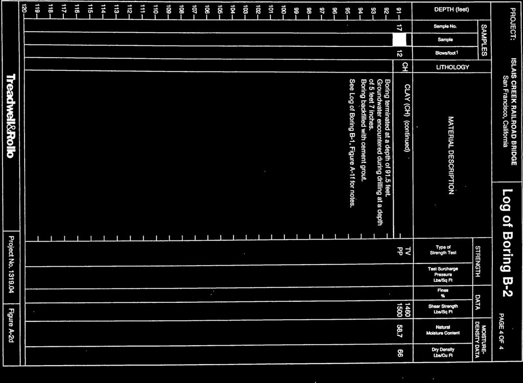
3 Bayview Gateway and Tulare Park Improvements Project August 2013 Page 3 of 10 to the maximum depth explored of feet. Boring B-17 (AGS, Inc.), was drilled approximately 47 feet north of the northern abutment of Third Street Bridge consists of approximately 43 feet of predominately clayey silty gravel with some silty and sand fill materials which were in turn underlain by approximately 35 feet of medium stiff to stiff Bay Mud. Below the Bay Mud, predominately very stiff silty clay soils with some sand lenses were encountered extending to the maximum depth explored of 123 feet. The fill thickness varies from about 23 to 43 feet. This extremely different thickness can occur within short distances and are typical of conditions where a mudwave has occurred. Mudwaves occur when fill is placed on a soft Bay Mud; when too much fill is placed in too short a time, a bearing capacity failure occurs. The approximate location of the testing borings is shown on Figure 2. Bayview Gateway Project Boring B-2(Treadwell & Rollo), drilled at the south abutment of Illinois Street Bridge encountered about 13 feet of loose to mediumm dense sandy gravel and medium stiff to stiff sandy clay fill. Approximately 12 feet of Bay Mud was encountered below the fill, which in turn is underlainn by 12 feet of medium to very densee gravel. Because Bay Mud was encountered between fill layers, it is likely the Bay Mud is fill or was displaced by fill placed during channel dredging. Below the gravel fill is natural Bay Mud, approximately 21 feet thick. A layer of dense to very dense sand with silt approximately 28 feet thick was encountered below the Bay Mud. The sand is underlainn by very stiff clay (Old Bay Clay) to the maximum depth explored of 91.5 feet. Boring B-18 (AGS, Inc.), was drilled approximately 40 feet south of the southern abutment of Third Street Bridge consists of approximately 23 feet of predominately clayeyy gravel and silty clay fill, which is in turn underlain by approximately 36 feet of medium stiff Bay Mud. The Bay Mud was in turn underlain by very stiff silty clay soils extending to the maximum depth explored of feet. The approximate location of the testing borings is shown on Figure 2. Groundwater Condition After the completion of soil boring, groundwater was measured in Borings B-1 and B-2 at levels of approximately 5.55 to 6 feet below the ground surface at the bridge abutments. This level may not represent a stabilized groundwater level; we expect groundwater levels in the area are controlled by the tidal variations in the channel. Groundwater should be assumed as much as 3 to 4 feet above sea level. Location Table 1 Summary of Test Borings Boring Designation Depth to Bottom of Fill (feet) Depth to Bottom of Bay Mud (feet) Depth to Bottom of Boring (feet) Tulare Park B-1* AGS B-17** Bayview Gateway B-2* AGS B-18** Note * Borings drilled at Illinois Street Bridge ** Borings drilled at Third Street Bridge San Francisco Department of Public Works Making San Francisco a beautiful, livable, vibrant, and sustainable city.
4 Bayview Gateway and Tulare Park Improvements Project August 2013 Page 4 of 10 Table 1 summarizes the test boring including elevations of the bottom of fill, Bay Mud, and borings. An idealized subsurface profile along the Illinois Street Bridge alignment is shown on Figure 3 and the previous boring logs for the Illinois Street and Third Street Bridges are included and shown on Appendix A. Pile Foundations Considering the presence of poor quality heterogeneous fill and weak, compressible Bay Mud at both project sites, we conclude the proposed pedestrian walkway and boardwalk be supported on driven piles. The piles should extend throughh the fill and weak Bay Mud, which are unsuitable for support, and gain support in the stiffer and denser soil below. Piles should gain support primarily in end bearing in the dense to very dense sand, roughly 130 feet below the existing ground surface at Tulare Park and 70 feet below the existing ground surface at Bayview Gateway. Because of the thickness and consistency of the competent sandy soil below the Bay Mud varies greatly from one location to another, we expect significant variations in pile lengths. It is our opinion that steel pipe pile may be used because the use of steel pipe pile permits flexibility of cutting off and adding on without compromising pile integrity, and can significantly reduce pile waste. Therefore, we are presenting recommendations for steel pipe piles in this memorandum. Pipe piles can be driven either open end or closed end. When driven open end, soil is allowed to enter the bottom of the pipe. If an empty pipe is required, a jet of water or an auger can be used to remove the soil inside following driving. Closed end pipe piles are constructed by covering the bottom of the pile with a steel plate or cast steel shoe. In some cases, pipe piles are filled with concrete to provide additional moment capacity or corrosion resistance. However, this is generally not done in order to reduce the cost. In thesee cases corrosion protection is provided by allowing for a sacrificial thickness of steel or by adopting a higher grade of steel. If a concretee filled pile is corroded, most of the load carrying capacity of the pile will remain intact due to the concrete, while it will be lost in an empty pile. The structural capacity of pipe pile is primarily calculated based on steel strength and concrete strength (if filled). An allowance is made for corrosion depending on the site conditions. Open-Ended Pipe Piles It is our opinion that open-endedd pipe piles may be used to provide support for the proposed pedestrian walkway and boardwalk. The open-ended pipe piles are non-displacement foundation elements as a result of reducing ground heaving such that it is unlikely to disturb the existing PUC sewer force main and other utilities in the close proximity. The pipe piles gain their axial capacity in friction along the shaft. Based on the results of our analyses, the piles need to be installed a minimum of 10 feet into very dense sand or receive refusal. Refusal should meet the requirements as discussed in detail in project drawings and specification; in general, refusal can be defined as when the pile installation blow count becomes less than six inches of penetration in fifty (50) blow counts. San Francisco Department of Public Works Making San Francisco a beautiful, livable, vibrant, and sustainable city.
5 Bayview Gateway and Tulare Park Improvements Project August 2013 Page 5 of 10 Since the existing utilities run through the project areas, to reduce vibrations during pile driving, pipe piles should be pre-drilled through the fill and Bay Mud to a depth of at least 25 feet to protect the existing utilities against disturbance. The diameter of the predrilled hole should not be greater than the nominal width of diameter of the pile. Pre-drilling will also reduce pile breakage through the fill, and maintain pile alignment. We also recommend the pipe piles be located a minimumm of 10 feet from the existing sewer force main. Due to the sloping bearing layer, pipe pile lengths will decrease from Tulare Park to Bayview Gateway; precise pile lengths cannot be determined priorr to driving. For estimating purposes, we recommend the bottom of Bay Mud is approximately 120 feet below the existing ground surface at Tulare Park and 60 feet below the existing ground surface at Bayview Gateway. The pipe piles can be designed for an allowable capacity of 200 kips in compression at Tulare Park and 100 kips in compression at Bayview Gateway with one-third increase for the seismic loads assuming the piles are driven to refusal of 10 feet below the top of the very dense sand layers. Based on the results of our analyses, the pipe piles should have a minimum spacing of 3 pile diameter center to center. It should note that if new fill is placed, the pipe piles will be subjected to downdrag loads, and pile capacities will be reduced due to the effect of downdrag. The structural capacity of the pipe piles needs to be confirmed by the project structural engineer. Lateral Resistance The pipe piles generally develop lateral resistance from the passive pressure acting on the upper portion of the piles and their structural rigidity. We developed load versus deflection and load versus moment curves based on a full section for both free-head and fixed-head condition for a 24-inch diameter pipe pile. The profiles of deflection, moment, and shear in the pipe pile for a range of lateral loads were generated. These profiles are presented in Figures 5 and 6 for Tulare Park and Figures 7 and 8 for Bayview Gateway. These lateral capacities are for single pipe pile only. Pile installed in a group of two spaced at least 3 pipe pile diameter center to center willl not adversely affect the pile resistance and capacity. Pile Test Program The objective of the pile test program is to: (1) validate the design assumptions used in the pile fictional shaft resistance and end bearing capacity, and (2) validate the pile head lateral deflection predictions under applied horizontal loads. Additionally, the success of installation method, particularly if pre-drilling is used is highly dependent on the performance of the pre- drilling in the fill layer. Pile test program will provide opportunities for the contractor to: (3) gain site experience at the project site; (4) develop acceptablee drilling and installationn methods to install test piles, and; (5) finalize the means and methods that will be used to install the production piles. We recommend at least one test pile be driven at each project site to observe the driving characteristics of the piles and the performance of the driving equipment. The test pile will provide blow count data to correlate with information obtained from the test borings, to aid in evaluating pre-drilling requirements and to be used as the basis for establishing final pile lengths. We also recommend using the same hammer type to drive the test and production piles. San Francisco Department of Public Works Making San Francisco a beautiful, livable, vibrant, and sustainable city.
6 Bayview Gateway and Tulare Park Improvements Project August 2013 Page 6 of 10 Pile Installation Determination of driving equipment for this project should take into account the matching of the pile hammer with the pile size and length. Special consideration should be given in selecting a hammer that can deliver enough energy to the tip of the piles to drive them efficiently without damagingg them. Pile driven with impact hammers shall be fitted with a helmet to distribute the hammer blow uniformly and concentrically to the pile head. The surface of the helmet in contact with the pile shall be plane and smooth and shall be aligned parallel with the hammer base and the pile head. For pipe piles which are approximately round sections are frequently driven using square helmets. If the helmet dimension is much larger than the pipe diameter, then a centering fixture is required. Appropriate driving heads, mandrels, or other devices shall be provided so that the piles may be driven without damage. Pipes installed open-ended may require a suitable cutting shoe. Pile shoes used at the option of the Contractor shall be of a type approved by the Engineer. TORQUE DOWN PILES It is our opinion that Torque Down piles may also be used because of its ability to unobtrusively install in close proximity to the existing sewer force main and other utilities. We recommend the torque down pile be located a minimum of 10 feet from the existing sewer force main. The Torque Down piles are displacement foundation elements and are screwed in place. The Torque Down piles gain their axial capacity both in friction along the shaft and end bearing. The majority of its capacity would be derived from end bearing in the very dense sand. The Torque Down 1275 pile is a full displacement pile consisting of a concrete filled, inch outside diameter steel pipe with a closed end conical tip welded to the bottom of the pipe. The steel pipe pile thickness is typically 3/8 inch. The piles are advancedd or screwed into the ground by application of torque and the weight of the drill rig. An advantage of the Torque Down 1275 system is to size the piles in the field becausee of the easee of adding on or subtracting to each pile during installation. A significant advantage is the displacement method of installation whichh typically results in very little construction spoils. Because the piles are installed using a displacement method, the presence of groundwater will not have an effect on installation and the installation results in little or no vibration. Similar to pipe pile, the torque down piles need to be installed a minimum of 10 feet into very dense sand or receivee refusal. Refusal will be defined as when the pile installation rate becomes less than one foot of penetration in ten (10) minutes, or when the torque required to install the pile exceeds 200,0000 foot-pounds. The torque down piles can be designed for an allowable capacity of 160 kips in compression and 80 kips in tension at Bayview Gateway and 80 kips in compression and 40 kips in tension at Bayview Gateway with one-third increase for the seismic loads. The structural capacity of the piles needs to be confirmed by the project structural engineer. Based on the results of our analyses, the torque down piles should have a minimum spacing of 3 pile diameter center to center. San Francisco Department of Public Works Making San Francisco a beautiful, livable, vibrant, and sustainable city.
7 Bayview Gateway and Tulare Park Improvements Project August 2013 Page 7 of 10 Lateral Resistance The Torque Down 1275 pile generally develops lateral resistance from the passive pressure acting on the upper portion of the piles and their structural rigidity. We developed load versus deflection and load versus moment curves based on a full section for both free-head and fixed- and shear in the pile for a range of lateral loads were generated. These profiles are presented in head condition for a inch diameter Torque Down Pile. The profiles of deflection, moment, Figures 9 and 10 for Tulare Park and Figures 11 and 12 for Bayview Gateway. These lateral capacities are for single pile only. Pile installed in a group of two be spaced at least 3 feet center to center will not adversely affect the pile resistance and capacity. Pile Test Program We recommend at least one test pile be installed at each project site to observe the installation characteristics of the piles and the performance of the equipment. The test pile will provide data to correlate with information obtained from the test borings, to aid in evaluating pre-drilling requirements and to be used as the basis for establishing final pile lengths. We also recommend using the same equipment to install the test and production piles. Corrosion Mitigation Measuress Bay Mud is considered potentially highly corrosive up to 20 feet below mud line. When pile is used in corrosive soil, special corrosion protection considerations for the steel pile may be needed. It is recommended that corrosion protection mitigation may include by allowing for a sacrificial thickness of steel in the upper portion of pile or by adopting a higher grade of steel and needs to be confirmed by the project structural engineer. Seismic Design Criteria The San Andreas Fault (Type A Fault as defined by the California Building Code) is the major active fault closest to the site. The main trace of the San Andreas Fault is situated about 12 kilometers southwest of the project site. For design in accordance with the 2010 California Building Code, we recommend the following: Peak Ground Acceleration (pga) for the Design Basis Earthquake (10% probability of exceedance in 50 years) of 0.48g. Site Class E Coefficients S MS of 1.35g and S M1 of 1.58g. Coefficients S DS of 0.90g and S D1 of 1.05g. Site Coefficients F a of 0.90 and F v of Construction Monitoring We recommend that the project geotechnical engineer review plans and specifications with regard to foundation and earthwork elements prior to construction bidding, in order to provide comments on the geotechnical aspects of the project. We further recommend that a representative of the geotechnical engineer be present to observe the pile test program and installation of the piles for the project. San Francisco Department of Public Works Making San Francisco a beautiful, livable, vibrant, and sustainable city.
8 Bayview Gateway and Tulare Park Improvements Project August 2013 Page 8 of 10 Pile installation will cause excessive noise and vibration and will adversely impact at the existing structures adjacent to the site, specifically the PUC sewer force main should be monitored for pile driving induced-displacement at various locations on structures. To evaluate the effects of vibrations during and vibrations during pile installation. Survey points should be established driving, ground vibration monitoring should be performed on adjacent structures. If excessive vibrations are recorded, pile driving operations should be halted and different methods of installation should be considered. Peak particle velocity at the ground surface in front of the adjacent structures should not exceed 0.1 inch per second or any site constraints per project requirements. All active utilities within the construction area should be protected during construction. We recommend the existing facilities within the influence zones of the proposed construction be protected from disturbance or damage prior to construction activities. Limitations No field investigationn was performed for this memorandum. The geotechnical discussions and recommendations made in this memorandumm are based on the assumption that the soil conditions do not deviate appreciably from those encountered in previous test borings by others. Furthermore, our evaluation is limited to the geotechnical aspects of the project and did not include evaluation of structural or environmental issues or presence of hazardous material at the site. The recommendations presented in this memorandum were developed with the Standard of Care commonly used as the state of the practice in the profession. No other warranties are included, either expressed or implied, as to the professional advice included in this memorandum. San Francisco Department of Public Works Making San Francisco a beautiful, livable, vibrant, and sustainable city.
9 Bayview Gateway and Tulare Park Improvements Project August 2013 Page 9 of 10 FIGURES San Francisco Department of Public Works Making San Francisco a beautiful, livable, vibrant, and sustainable city.

10 Tulare Park Bayview Gateway July 2013 Contract No. 1781J SITE LOCATION MAP Bayview Gateway and Tulare Park Improvement Project San Francisco, California FIGURE 1

11 Tulare Park Bayview Gateway Approximate Location of Test Borings by AGS, February 2000 Approximate Location of Test Borings by Treadwell & Rollo, May 1997 and August 2001 Approximate Location of Test Borings by Treadwell & Rollo, January 2004 Approximate Location of Test Borings by Treadwell & Rollo, April 2004 July 2013 Contract No. 1781J VICINITY MAP Bayview Gateway and Tulare Park Improvement Project San Francisco, California FIGURE 2

12 NOTE: 1. Idealized subsurface profile was prepared by Treadwell & Rollo, dated December The above profile represents a generalized soil cross section interpreted from widely spaced borings. Soil deposits may vary in type, strength, and other important properties between points of exploration. IDEALIZED SUBSURFACE PROFILE ALONG ILLINOIS STREET BRIDGE IN THE VICINITY OF TULARE PARK Bayview Gateway and Tulare Park July 2013 Improvement Project Project No. 1781J San Francisco, California FIGURE 3

13 NOTE: 1. Idealized subsurface profile was prepared by Treadwell & Rollo, dated December The above profile represents a generalized soil cross section interpreted from widely spaced borings. Soil deposits may vary in type, strength, and other important properties between points of exploration. IDEALIZED SUBSURFACE PROFILE ALONG ILLINOIS STREET BRIDGE IN VICINITY OF BAYVIEW GATEWAY Bayview Gateway and Tulare Park July 2013 Improvement Project Project No. 1781J San Francisco, California FIGURE 4
14 Depth, feet T&R B-1 (~ ) FILL BAY MUD Bending Moment (kip-ft) Deflection (inch) Notes: kips axial load and 20 kip-ft bending moment applied to head of pipe pile. 2. Passive resistance of pile caps/footing has not been included. 3. Soil Profile based on existing boring (T&R B-1) in the site vicinity Shear (kip) FREE HEAD SUMMARY OF NUMERICAL ANALYSES OPEN-ENDED PIPE PILE (Do = 24") for TULARE PARK July 2013 Project No. 1781J Bayview Gateway and Tulare Park Improvement Project San Francisco, California FIGURE 5
15 Depth, feet T&R B-1 (~ ) FILL BAY MUD Bending Moment (kip-ft) Deflection (inch) Notes: kips axial load and 20 kip-ft bending moment applied to head of pipe pile. 2. Passive resistance of pile caps/footing has not been included. 3. Soil Profile based on existing boring (T&R B-1) in the site vicinity Shear (kip) FIXED HEAD SUMMARY OF NUMERICAL ANALYSES OPEN-ENDED PIPE PILE (Do = 24") for TULARE PARK July 2013 Project No. 1781J Bayview Gateway and Tulare Park Improvement Project San Francisco, California FIGURE 6
16 T&R B-2 (~ ) Depth, feet FILL BAY MUD Bending Moment (kip-ft) Deflection (inch) Notes: kips axial load and 20 kip-ft bending moment applied to head of pipe pile. 2. Passive resistance of pile caps/footing has not been included. 3. Soil Profile based on existing boring (T&R B-2) in the site vicinity Shear (kip) FREE HEAD SUMMARY OF NUMERICAL ANALYSES OPEN-ENDED PIPE PILE (Do = 24") for BAYVIEW GATEWAY July 2013 Project No. 1781J Bayview Gateway and Tulare Park Improvement Project San Francisco, California FIGURE 7
17 T&R B-2 (~ ) Depth, feet FILL BAY MUD Bending Moment (kip-ft) Deflection (inch) Notes: kips axial load and 20 kip-ft bending moment applied to head of pipe pile. 2. Passive resistance of pile caps/footing has not been included. 3. Soil Profile based on existing boring (T&R B-2) in the site vicinity Shear (kip) FIXED HEAD SUMMARY OF NUMERICAL ANALYSES OPEN-ENDED PIPE PILE (Do = 24") for BAYVIEW GATEWAY July 2013 Project No. 1781J Bayview Gateway and Tulare Park Improvement Project San Francisco, California FIGURE 8
18 Depth, feet T&R B-1 (~ ) FILL BAY MUD Bending Moment (kip-ft) Deflection (inch) Notes: kips axial load and 20 kip-ft bending moment applied to head of pile. 2. Passive resistance of pile caps/footing has not been included. 3. Soil Profile based on existing boring (T&R B-1) in the site vicinity Shear (kip) FREE HEAD SUMMARY OF NUMERICAL ANALYSES TORQUE DOWN PILE (Do = 12.75") for TULARE PARK July 2013 Project No. 1781J Bayview Gateway and Tulare Park Improvement Project San Francisco, California FIGURE 9
19 Depth, feet T&R B-1 (~ ) FILL BAY MUD Bending Moment (kip-ft) Deflection (inch) Notes: kips axial load and 20 kip-ft bending moment applied to head of pile. 2. Passive resistance of pile caps/footing has not been included. 3. Soil Profile based on existing boring (T&R B-1) in the site vicinity Shear (kip) FIXED HEAD SUMMARY OF NUMERICAL ANALYSES TORQUE DOWN PILE (Do = 12.75") for TULARE PARK July 2013 Project No. 1781J Bayview Gateway and Tulare Park Improvement Project San Francisco, California FIGURE 10
20 T&R B-2 (~ ) Depth, feet FILL BAY MUD Bending Moment (kip-ft) Deflection (inch) Notes: kips axial load and 20 kip-ft bending moment applied to head of pile. 2. Passive resistance of pile caps/footing has not been included. 3. Soil Profile based on existing boring (T&R B-2) in the site vicinity Shear (kip) FREE HEAD SUMMARY OF NUMERICAL ANALYSES TORQUE DOWN PILE (Do = 12.75") for BAYVIEW GATEWAY July 2013 Project No. 1781J Bayview Gateway and Tulare Park Improvement Project San Francisco, California FIGURE 11
21 T&R B-2 (~ ) Depth, feet FILL BAY MUD Bending Moment (kip-ft) Deflection (inch) Notes: kips axial load and 20 kip-ft bending moment applied to head of pile. 2. Passive resistance of pile caps/footing has not been included. 3. Soil Profile based on existing boring (T&R B-2) in the site vicinity Shear (kip) FIXED HEAD SUMMARY OF NUMERICAL ANALYSES TORQUE DOWN PILE (Do = 12.75") for BAYVIEW GATEWAY July 2013 Project No. 1781J Bayview Gateway and Tulare Park Improvement Project San Francisco, California FIGURE 12
22 Bayview Gateway and Tulare Park Improvements Project August 2013 Page 10 of 10 APPENDIX A (Previous Boring Logs) San Francisco Department of Public Works Making San Francisco a beautiful, livable, vibrant, and sustainable city.

23

24

25

26

27

28

29

30

31
32

33

34


35


36


37


38
39
40
41
42
43
44
45
46
47
48
49
50
51
52
53
54
55
56
57
58
59
60
61
62
63
64
65
Earth Mechanics, Inc. Geotechnical & Earthquake Engineering
 Earth Mechanics, Inc. Geotechnical & Earthquake Engineering TECHNICAL MEMORANDUM DATE: June 3, 2009 EMI PROJECT NO: 01-143 TO: COPY: FROM: SUBJECT: John Chun, P.E. / Port of Long Beach (POLB) Jorge Castillo
HURRICANE SANDY LIMITED REEVALUATION REPORT UNION BEACH, NEW JERSEY DRAFT ENGINEERING APPENDIX SUB APPENDIX B-2 FLOODWALL PILE ANALYSES EAST WALLS
 HURRICANE SANDY LIMITED REEVALUATION REPORT UNION BEACH, NEW JERSEY DRAFT ENGINEERING APPENDIX SUB APPENDIX B-2 FLOODWALL PILE ANALYSES EAST WALLS Revised March 2015 Preliminary Flood Wall Pile Analysis
Implementation of this Special Provision requires a complete understanding of the following documents:
 VIRGINIA DEPARTMENT OF TRANSPORTATION SPECIAL PROVISION FOR Quality Assurance/Quality Control (QA/QC) for the Construction of Deep Foundation Systems for Design-Build and PPTA Contracts November 10, 2009
Over the last decade, drilled and postgrouted micropile foundations have
 Seismic Design of Micropile Foundation Systems Leo Panian, S.E., and Mike Korolyk, S.E. Over the last decade, drilled and postgrouted micropile foundations have come to be increasingly relied on for resisting
April 7, Webster Street Sub-Surface Stormwater Storage System Bid No Bid Date: 4/13/17 ADDENDUM NO 1
 PUBLIC WORKS DEPARTMENT David A. Jones, P.E., Director April 7, 2017 Webster Street Sub-Surface Stormwater Storage System Bid No. 2017-022 Bid Date: 4/13/17 ADDENDUM NO 1 Please make the following changes
Design and Construction of Drilled Full Displacement Piles using the Penetration Resistance Method
 SUPERPILE 2009 Burlingame, CA Design and Construction of Drilled Full Displacement Piles using the Penetration Resistance Method Peter Faust Malcolm Drilling Company Inc. Alexandria Parking Garage, San
DIVISION: EARTHWORK SECTION: BORED PILES REPORT HOLDER: GEOTECH ENTERPRISES, INC.
 0 Most Widely Accepted and Trusted ICC ES Report ICC ES 000 (800) 423 6587 (562) 699 0543 www.icc es.org ESR 3623 Reissued 04/2017 This report is subject to renewal 04/2018. DIVISION: 31 00 00 EARTHWORK
UNDERPINNING A CRANE FOUNDATION
 UNDERPINNING A CRANE FOUNDATION Donald R. McMahon, P.E., McMahon & Mann Consulting Engineers, P.C., Buffalo, New York, USA Andrew J. Nichols, P.E., McMahon & Mann Consulting Engineers, P.C., Buffalo, New
GEOTECHNICAL RESISTANCE FACTORS
 Chapter 9 GEOTECHNICAL RESISTANCE FACTORS Final SCDOT GEOTECHNICAL DESIGN MANUAL 9-i Table of Contents Section Page 9.1 Introduction... 9-1 9.2 Soil Properties... 9-2 9.3 Resistance Factors for LRFD Geotechnical
OPEN CELL. (800) SWC 120. SWC Weld-on. Charts and Pictures courtesy of: 120 o
 SWC 120. SWC Weld-on. Charts and Pictures courtesy of: 120 o") OPEN CELL The OPEN CELL bulkhead, used primarily on docks and similar structures, is a cellular flat sheet pile structure in which each cell s sheet piles are driven in the shape of a U when viewed from
OPEN CELL The OPEN CELL bulkhead, used primarily on docks and similar structures, is a cellular flat sheet pile structure in which each cell s sheet piles are driven in the shape of a U when viewed from
Subsurface Investigation Report. Proposed New 1-Story Building 6447 Grand Avenue Gurnee, Illinois
 AGI Project No. -11 Subsurface Investigation Report For the Proposed New 1-Story Building 6447 Grand Avenue Gurnee, Illinois Prepared for Mr. Steve Panko Key Development Partners, LLC North State Street,
Applied GeoScience, Inc Hammond Dr., Suite 6 Schaumburg, Illinois
 AGI Project No. 13-276 Subsurface Investigation Report For the Proposed New Retail Center 9601 South Pulaski Road Evergreen Park, Illinois Prepared for Mr. Feras Sweis FHS Design + Build LLC 2010 West
NONLINER STIFFNESS MATRIX MODELING FOR COMPLEX PILE GROUP FOUNDATION OF THE ANCHORAGE PORT ACCESS BRIDGE
 10NCEE Tenth U.S. National Conference on Earthquake Engineering Frontiers of Earthquake Engineering July 21-25, 2014 Anchorage, Alaska NONLINER STIFFNESS MATRIX MODELING FOR COMPLEX PILE GROUP FOUNDATION
PROJECT NO A. ISSUED: February 29, 2016
 INTERPRETIVE REPORT FOR INFILTRATION SYSTEM DESIGN, PROPOSED VILLA VERONA APARTMENT COMMUNITY, ASSESSOR S PARCEL NUMBERS 311-040-015, 311-040-021, 311-040-024, 311-040-026 AND 311-040-013, LOCATED ON THE
APPENDIX J.2 GEOTECHNICAL TEST RESULTS
 APPENDIX J.2 GEOTECHNICAL TEST RESULTS GEOTECHNICAL INVESTIGATION CARMEL LOFTS Sunnyvale, California Carmel Partners, Inc. San Francisco, California 18 January 2012 Project 73176301 18 January 2012 Project
Performance of Mechanically Stabilized Earth walls over compressible soils
 Performance of Mechanically Stabilized Earth walls over compressible soils R.A. Bloomfield, A.F. Soliman and A. Abraham The Reinforced Earth Company, Vienna, Virginia, USA ABSTRACT: Two projects have recently
NPTEL Course GROUND IMPROVEMENT USING MICROPILES
 Lecture 22 NPTEL Course GROUND IMPROVEMENT USING MICROPILES Prof. G L Sivakumar Babu Department of Civil Engineering Indian Institute of Science Bangalore 560012 Email: gls@civil.iisc.ernet.in Contents
Determination of Design Infiltration Rates for the Sizing of Infiltration based Green Infrastructure Facilities
 Determination of Design Infiltration Rates for the Sizing of Infiltration based Green Infrastructure Facilities 1 Introduction This document, developed by the San Francisco Public Utilities Commission
PDPI 2015 STATIC ANALYSIS LATERALLY LOADED PILE DESIGN. Chapter 9
 PDPI 2015 STATIC ANALYSIS LATERALLY LOADED PILE DESIGN Chapter 9 Lateral Capacity of Single Piles Potential sources of lateral loads include vehicle acceleration & braking, wind loads, wave loading, debris
Application of Vibro Techniques for Infrastructure Projects in India
 Application of Vibro Techniques for Infrastructure Projects in India Rainer Wegner Contract Manager, Keller Grundbau GmbH, Germany Dr. V.R. Raju Director, Keller Ground Engineering India Pvt Ltd, India
Offshore pile acceptance using dynamic pile monitoring
 Offshore pile acceptance using dynamic pile monitoring Webster, S. & Givet, R. GRL Engineers, Inc. Charlotte, NC, USA Griffith, A. Saudi Aramco, Dhahran, Saudi Arabia ABSTRACT: Dynamic pile monitoring
Pile Design from Constructability Perspective
 Pile Design from Constructability Perspective Prestressed Concrete Piles in Coastal Georgia Presented by: Guoming Lin, Ph.D., G.E., D.GE Senior Principal / Senior Consultant Savannah, Georgia November
RIGID INCLUSIONS. Rigid Inclusions offer an economical approach for building on sites underlain by soft soil.
 H A Y W A R D B A K E R I N C. RIGID INCLUSIONS Rigid Inclusions offer an economical approach for building on sites underlain by soft soil. Above: HBI installed Rigid Inclusions on a congested downtown
ADDENDUM No. 6. ITB No. 4424: W.R. Wheeler (Swift Run) Service Center PUD Non-motorized Improvements Phase 1
 Service Center PUD Non-motorized Improvements Phase 1") ADDENDUM No. 6 ITB No. 4424: W.R. Wheeler (Swift Run) Service Center PUD Non-motorized Improvements Phase 1 Due: June 9, 2016 at 2:00 p.m. (local time) The following changes, additions, and/or deletions
ADDENDUM No. 6 ITB No. 4424: W.R. Wheeler (Swift Run) Service Center PUD Non-motorized Improvements Phase 1 Due: June 9, 2016 at 2:00 p.m. (local time) The following changes, additions, and/or deletions
OFFICE OF STATE AID ROAD CONSTRUCTION MISSISSIPPI DEPARTMENT OF TRANSPORTATION
 Supplemental Specification 901-S-803-1 LFRD Driven Pile Specifications. DATE: May 24, 2010 OFFICE OF STATE AID ROAD CONSTRUCTION MISSISSIPPI DEPARTMENT OF TRANSPORTATION SUBJECT: LRFD Driven Pile Specifications
DIVISION: EARTHWORK SECTION: BORED PILES REPORT HOLDER: GOLIATHTECH INCORPORATED 175B RUE PELADEAU MAGOG, QUEBEC J1X 5G9 CANADA
 0 Most Widely Accepted and Trusted ICC-ES Evaluation Report ICC-ES 000 (800) 423-6587 (562) 699-0543 www.icc-es.org ESR-3726 Issued 10/2017 This report is subject to renewal 10/2018. DIVISION: 31 00 00
SECTION DUCTILE IRON PILES
 SECTION 31 66 13 DUCTILE IRON PILES PART 1 - GENERAL 1.1 GENERAL REQUIREMENTS A. Work of this Section, as shown or specified, shall be in accordance with the requirements of the Contract Documents. B.
Subsurface Investigation Report
 AGI Project No. 17-154 Subsurface Investigation Report For the Proposed New One-Story Building Addition 7030 West 111 th Street Worth, Illinois Prepared for T63 Development LLC 11052 Mayflow er Lane Orland
Prepared for: HDR Engineering, Inc. 200 West Forsyth Street, Suite 800 Jacksonville, Florida Prepared by:
 REPORT OF GEOTECHNICAL EXPLORATION REHABILITATE WHARF STRUCTURE AT BERTHS 6 AND ½ OF BERTH 5 TALLEYRAND MARINE TERMINAL, JACKSONVILLE, FLORIDA E&A PROJECT NO. 0756-0081 Prepared for: HDR Engineering, Inc.
Subsurface Environmental Investigation
 Subsurface Environmental Investigation Lake Development East Lake and 21 st Avenue South February 23, 201 Terracon Project No. MP14738A Prepared for: Minneapolis Public Schools Prepared by: Terracon Consultants,
A Case History of Pile Freeze Effects in Dense Florida Sands
 A Case History of Pile Freeze Effects in Dense Florida Sands By Ching Kuo 1, Guoan Cao 2, Amy L. Guisinger 3, and Paul Passe 4 Submission Date: August 1, 2006 2,804 Words 1 Table 5 Figures 1 Professional
PART VII - WATER SYSTEM DESIGN CRITERIA
 PART VII - WATER SYSTEM DESIGN CRITERIA A. Water Distribution, General 1. The water system layout shall be approved by the City Engineer. The fire hydrant layout shall be approved by the Redwood City Fire
DUCTILE IRON PILES ARE HIGHLY EFFECTIVE, FAST AND VERSATILE MODULAR DRIVEN MICROPILE SYSTEMS
 DUCTILE IRON PILES DUCTILE IRON PILES ARE HIGHLY EFFECTIVE, FAST AND VERSATILE MODULAR DRIVEN MICROPILE SYSTEMS Designed to resist both compression and tension loads in either end-bearing or friction,
GEOTECHNICAL INVESTIGATION I-15 SIGN BRIDGES LAS VEGAS EA JANUARY
 GEOTECHNICAL INVESTIGATION I-15 SIGN BRIDGES LAS VEGAS EA 73171 JANUARY 06 MATERIALS DIVISION STATE OF NEVADA DEPARTMENT OF TRANSPORTATION MATERIALS DIVISION GEOTECHNICAL SECTION GEOTECHNICAL REPORT I-15
USE OF DIPP PILES FOR A NEW SUP BRIDGE IN WEST MELBOURNE
 USE OF DIPP PILES FOR A NEW SUP BRIDGE IN WEST MELBOURNE If you want to put a photo on the title slide use this layout with colour photos (delete this box) Michael Wei, Jawad Zeerak & David Barton 8 th
Steven Dapp, Ph.D., P.E. Steven Dapp, Ph.D., P.E. Dan Brown and Associates
 LA Transportation Conference: 10 Jan 2011 Drilled Shaft Foundations For Two Mississippi River Bridges in Louisiana Dan Brown and Associates Projects John James Audubon Bridge, St. Francisville New Construction
Construction Planning, Equipment, and Methods PILES AND PILE-DRIVING EQUIPMENT
 CHAPTER Construction Planning, Equipment, and Methods PILES AND PILE-DRIVING EQUIPMENT Sixth Edition A. J. Clark School of Engineering Department of Civil and Environmental Engineering 19 By Dr. Ibrahim
aggregate piers / vscs
 aggregate piers / vscs 1 2 HT1.0 1-1 1-2 1' - 1" 34' - 0" 16' - 11" 1' - 1" 13' - 10" BOF 817' - 6" (TYPICAL WITHIN HATCHED REGION) 1-17 1-32 1-47 1-62 1-3 1-18 1-33 1-48 1-63 1-4 1-19 1-34 1-49 1-64 1-5
Using Thermal Integrity Profiling to Confirm the Structural Integrity of foundation applications
 Using Thermal Integrity Profiling to Confirm the Structural Integrity of foundation applications Authors: 1. George Piscsalko, PE, Pile Dynamics, Inc., 30725 Aurora Road, Solon, Ohio, USA, gpiscsalko@pile.com;
Experience of a Large Scale Unintentionally Long Surcharge on Organic Soils
 Experience of a Large Scale Unintentionally Long Surcharge on Organic Soils Ying Liu, Ph.D., P.E., Senior Engineer, Group Delta Consultants, Inc., 37 Amapola Ave., Suite 212, Torrance, CA. Email: yingl@groupdelta.com
REPORT OF SUBSURFACE INVESTIGATION AND GEOTECHNICAL ENGINEERING SERVICES. Proposed Soundside Boardwalk Expansion Duck, North Carolina
 REPORT OF SUBSURFACE INVESTIGATION AND GEOTECHNICAL ENGINEERING SERVICES Proposed Soundside Boardwalk Expansion Duck, North Carolina G E T PROJECT NO: EC10-260G November 17, 2010 Prepared for VHB, Inc.
DIVISION: EARTHWORK SECTION: BORED PILES REPORT HOLDER: HELICAL ANCHORS, INC BOONE AVENUE, NORTH MINNEAPOLIS, MINNESOTA 55428
 0 Most Widely Accepted and Trusted ICC-ES Evaluation Report ICC-ES 000 (800) 423-6587 (562) 699-0543 www.icc-es.org ESR-3982 Reissued 09/2017 This report is subject to renewal 09/2019. DIVISION: 31 00
Marina Bay Sands Hotel Arch 631 Kayla Brittany Maria Michelle
 Marina Bay Sands Hotel Arch 631 Kayla Brittany Maria Michelle Overall Information Location: Singapore Date of Completion: 2010 Cost: $5.7 billion Architect: Moshe Safdie Executive Architect: Aedas, Pte
DIVISION: EARTHWORK SECTION: BORED PILES REPORT HOLDER: MAGNUM PIERING, INC. 156 CIRCLE FREEWAY DRIVE CINCINNATI, OHIO 45246
 0 Most Widely Accepted and Trusted ICC ES Evaluation Report ICC ES 000 (800) 423 6587 (562) 699 0543 www.icc es.org ESR 2997 Reissued 05/2017 This report is subject to renewal 05/2018. DIVISION: 31 00
First Applications of the SAVE Compozer Method (Non-Vibratory Stone Columns) for Soil Densification in the U.S.
 for Soil Densification in the U.S.") GSP 181 28 ASCE First Applications of the SAVE Compozer Method (Non-Vibratory Stone Columns) for Soil Densification in the U.S. Jun Mukai 1, Masaru Sakakibara 2, Juan I. Baez, Ph.D., P.E 3, Sean G. Callan,
GSP 181 28 ASCE First Applications of the SAVE Compozer Method (Non-Vibratory Stone Columns) for Soil Densification in the U.S. Jun Mukai 1, Masaru Sakakibara 2, Juan I. Baez, Ph.D., P.E 3, Sean G. Callan,
Please include this addendum in your Bid proposal for the above referenced project. Questions are in black ink, and the answers are in red ink.
 JAHarchitects, LLC PROJECT NO. 393 RIVERCREST CDD 11560 RAMBLE CREEK DRIVE, RIVERVIEW FL ADDENDUM TO BID PROJECT: RIVERCREST CDD MULTI PURPOSE FIELD MAINTENANCE BUILDING & DOG PARK POOL & CABANNA JAH PROJECT
BACKGROUND: SUBSURFACE CONDITIONS:
 2 BACKGROUND: The planned project consists of a prefabricated modular apartment building with underground parking, located on the site bounded by Dexter Avenue N. to the east, multi-story residential/commercial
Modelling of a pile row in a 2D plane strain FE-analysis
 Numerical Methods in Geotechnical Engineering Hicks, Brinkgreve & Rohe (Eds) 2014 Taylor & Francis Group, London, 978-1-138-00146-6 Modelling of a pile row in a 2D plane strain FE-analysis J.J.M. Sluis,
Bond Strength of Hollow-Core Bar Micropiles
 Missouri University of Science and Technology Scholars' Mine International Conference on Case Histories in Geotechnical Engineering (28) - Sixth International Conference on Case Histories in Geotechnical
This report presents the findings of the subsurface exploration concerning the design of the taxiway rehabilitation. Description
 September 22, 2016 American Infrastructure Development, Inc. 3810 Northdale Boulevard, Suite 170 Tampa, Florida 33624 Attn: Mr. Mohsen Mohammadi, Ph.D., P.E. Senior Consultant Mob: (813) 244-6609 E-mail:
GEOTECHNICAL INVESTIGATION For PROPOSED OUTDOOR THEATER 495 Upper Park Road APN Santa Cruz, California
 GEOTECHNICAL INVESTIGATION For PROPOSED OUTDOOR THEATER 495 Upper Park Road APN 009-301-06 Santa Cruz, California Prepared For SANTA CRUZ SHAKESPEAR Santa Cruz, California Prepared By DEES & ASSOCIATES,
BLEINC. August 17, Black & Veatch Corporation 201 Brookfield Parkway, Suite 150 Greenville, SC 29607
 BLEINC. BUNNELL-LAMMONS ENGINEERING, INC. GEOTECHNICAL, ENVIRONMENTAL AND CONSTRUCTION MATERIALS CONSULTANTS August 17, 2017 Black & Veatch Corporation 201 Brookfield Parkway, Suite 150 Greenville, SC
Temporary Structures. Excavations and Excavation Supports
 UNIVERSITY OF WASHINGTON DEPARTMENT OF CONSTRUCTION MANAGEMENT CM 420 TEMPORARY STRUCTURES Winter Quarter 2007 Professor Kamran M. Nemati Temporary Structures Excavations and Excavation Supports CM 420
A Case Study: Foundation Design in Liquefiable Site
 RESEARCH ARTICLE OPEN ACCESS A Case Study: Foundation Design in Liquefiable Site Tahar Ayadat* *(Department of Civil Engineering, College of Engineering, PMU University, P.O. Box 1664, Al-Khobar, 31952,
Oweninny Wind Farm. Oweninny Environmental Impact Statement Appendix 5. Turbine Foundation Construction Method Statement
 Oweninny Wind Farm Oweninny Environmental Impact Statement Appendix 5 Turbine Foundation Construction Method Statement Copyright ESB International Limited, all rights reserved. Farm Contents 1 Introduction
Minimum Guidelines for the Design and Use of Underpins When Performing Foundation Stabilization and/or Supplementation UP-08
 Minimum Guidelines for the Design and Use of Underpins When Performing Foundation Stabilization and/or Supplementation UP-08 Table of Contents 1. Title 2. Designation 3. List of Figures 4. Scope 5. Referenced
Monitoring a Drilled Shaft Retaining Wall in Expansive Clay: Long-Term Performance in Response to Moisture Fluctuations
 1348 Brown, A.C., Dellinger, G., Helwa, A., El-Mohtar, C., Zornberg, J.G., and Gilbert, R.B. (2015). Monitoring a Drilled Shaft Retaining Wall in Expansive Clay: Long-Term Performance in Response to Moisture
Typical Subsurface Profile. November 28, 2016
 November 28, 2016 RSCCD Facility Planning, District Construction and Support Services 2323 N. Broadway, Suite 112, Santa Ana, CA 92706 Attn: Re: Ms. Allison Coburn Facilities Project Manager P: (714) 480-7530
GEOTECHNICAL EXPLORATION
 GEOTECHNICAL EXPLORATION SAN MATEO COUNTY REPLACEMENT CORRECTIONAL FACILITY REDWOOD CITY, CALIFORNIA Submitted to: Mr. Sam Lin San Mateo County Sheriff s Office Jail Planning Unit 400 County Center, 3rd
Design Data 4. Jacking Concrete Pipe
 Design Data 4 Jacking Concrete Pipe FOREWORD Jacking or tunneling concrete pipe is an increasingly important construction method for installing concrete pipelines without interrupting commerce, or disturbing
AL HAMRA TOWER KUWAIT CITY, KUWAIT SARAH CLAUS, VICTORIA GARCIA, AMBER HOLDEN-O DONNELL, ERICA SCHNEIDER, HANNAH VOSSLER
 AL HAMRA TOWER KUWAIT CITY, KUWAIT SARAH CLAUS, VICTORIA GARCIA, AMBER HOLDEN-O DONNELL, ERICA SCHNEIDER, HANNAH VOSSLER DESIGNED AND ENGINEERED BY SKIDMORE, OWINGS AND MERRILL CONSTRUCTED FROM 2005-2011
DIVISION: EARTHWORK SECTION: BORED PILES REPORT HOLDER: EMPIRE PIERS 2656 EAST HWY 47 WINFIELD, MO EVALUATION SUBJECT:
 0 Most Widely Accepted and Trusted ICC-ES Evaluation Report ICC-ES 000 (800) 423-6587 (562) 699-0543 www.icc-es.org ESR-4050 Issued 12/2017 This report is subject to renewal 12/2018. DIVISION: 31 00 00
A CASE HISTORY ON DESIGN, CONSTRUCTION, AND PERFORMANCE OF STONE COLUMN GROUND IMPROVEMENT BENEATH AN MSE EMBANKMENT
 A CASE HISTORY ON DESIGN, CONSTRUCTION, AND PERFORMANCE OF STONE COLUMN GROUND IMPROVEMENT BENEATH AN MSE EMBANKMENT Karen Dawson, P.E. and Seungcheol Shin, Ph.D., P.E., CH2M HILL, Bellevue, WA, USA Suthan
DIVISION: EARTHWORK SECTION: BORED PILES REPORT HOLDER: CANTSINK MANUFACTURING, INC. 71 FIRST AVENUE LILBURN, GEORGIA 30047
 0 Most Widely Accepted and Trusted ICC-ES Evaluation Report ICC-ES 000 (800) 423-6587 (562) 699-0543 www.icc-es.org ESR-1559 Reissued 12/2016 This report is subject to renewal 12/2018. DIVISION: 31 00
Chapter A-8 GEOTECHNICAL ANALYSIS FAIRFAX-JERSEY CREEK (JERSEY CREEK SHEET PILE WALL)
") Kansas Citys, Missouri and Kansas Flood Damage Reduction Feasibility Study (Section 216 Review of Completed Civil Works Projects) Engineering Appendix to the Interim Feasibility Report Chapter A-8 GEOTECHNICAL
Kansas Citys, Missouri and Kansas Flood Damage Reduction Feasibility Study (Section 216 Review of Completed Civil Works Projects) Engineering Appendix to the Interim Feasibility Report Chapter A-8 GEOTECHNICAL
King County Uses Trenchless Methods to Construct a Large Siphon Under Seattle s Ship Canal
 North American Society for Trenchless Technology (NASTT) NASTT s 2013 No-Dig Show Sacramento, California March 3-7, 2013 TA-T1-03 King County Uses Trenchless Methods to Construct a Large Siphon Under Seattle
INNOVATIVE PILE EXTRACTION TECHNIQUE OF CFA PILES FOR THE NEW HARBOR BRIDGE PROJECT
 INNOVATIVE PILE EXTRACTION TECHNIQUE OF CFA PILES FOR THE NEW HARBOR BRIDGE PROJECT Tracy Brettmann, P.E., D.GE, Vice President, A. H. Beck Foundation Company, Houston, Texas, (713) 413-3800, tracy.brettmann@ahbeck.com
Panduit Corporation Tinley Park, Illinois. Outset and Inset Cabinets Seismic Load Rating and Anchorage Design
 Panduit Corporation Tinley Park, Illinois Outset and Inset Cabinets Seismic Load Rating and Anchorage Design February 13, 2013 Degenkolb Job Number B2439007.00 www.degenkolb.com 500 Degenkolb Engineers
August 15, 2006 (Revised) July 3, 2006 Project No A
 July 3, 2006 Project No A") August 15, 2006 (Revised) July 3, 2006 Project No. 01-05-0854-101A Mr. David Reed, P.E. Protean Design Group 100 East Pine Street, Suite 306 Orlando, Florida 32801 Preliminary Soil Survey Report Polk Parkway
August 15, 2006 (Revised) July 3, 2006 Project No. 01-05-0854-101A Mr. David Reed, P.E. Protean Design Group 100 East Pine Street, Suite 306 Orlando, Florida 32801 Preliminary Soil Survey Report Polk Parkway
DIVISION: EARTHWORK SECTION: BORED PILES REPORT HOLDER: IDEAL MANUFACTURING, INC. 999 PICTURE PARKWAY WEBSTER, NEW YORK 14580
 0 Most Widely Accepted and Trusted ICC-ES Evaluation Report ICC-ES 000 (800) 423-6587 (562) 699-0543 www.icc-es.org ESR-3750 Reissued 06/2017 This report is subject to renewal 06/2018. DIVISION: 31 00
ACCEPTANCE CRITERIA FOR HELICAL PILE SYSTEMS AND DEVICES PREFACE
 www.icc-es.org (800) 423-6587 (562) 699-0543 A Subsidiary of the International Code Council ACCEPTANCE CRITERIA FOR HELICAL PILE SYSTEMS AND DEVICES AC358 Approved June 2012 Compliance date December 1,
Requirements for Foundations on Liquefiable Sites
 Requirements for Foundations on Liquefiable Sites Robert Bachman, S.E. R. E. Bachman Consulting Structural Engineers Laguna Niguel, CA 1 Issue Team and ASCE 7 Contributing Members Evolved and Improved
REPORT OF SUBSURFACE EXPLORATION
 REPORT OF SUBSURFACE EXPLORATION WELDING & JOINING TECHNOLOGY FACILITY NORTH GEORGIA TECHNICAL COLLEGE CLARKESVILLE, GEORGIA S&ME PROJECT NO. 161-10-061 Prepared For: LW Engineering, P.C. Post Office Box
SCG INTERNATIONAL TRINIDAD AND TOBAGO LIMITED COUVA CHILDREN S HOSPITAL
 SCG INTERNATIONAL TRINIDAD AND TOBAGO LIMITED COUVA CHILDREN S HOSPITAL GEOTECHNICAL CONSULTANT Prepared by Checked by Approved by Mr. C Allen Dr. Derek Gay Dr. Derek Gay Signature Date Signature Date
GEOTECHNICAL ENGINEERING REPORT
 GEOTECHNICAL ENGINEERING REPORT PROJECT MINECRAFT ACCESS ROAD BOYDTON PLANK ROAD DINWIDDIE COUNTY, VIRGINIA JOB NUMBER: 37775.003 PREPARED FOR: DINWIDDIE COUNTY PO BOX 70 DINWIDDIE COUNTY, STATE 23841
RECOMMENDED PROCEDURES FOR IMPLEMENTAION OF DMG SPECIAL PUBLICATION 117 GUIDELINES FOR ANALYZING AND MITIGATING LIQUEFACTION IN CALIFORNIA
 RECOMMENDED PROCEDURES FOR IMPLEMENTAION OF DMG SPECIAL PUBLICATION 117 GUIDELINES FOR ANALYZING AND MITIGATING LIQUEFACTION IN CALIFORNIA SECTION 5.0 FIELD INVESTIGATIONS 5.0 FIELD INVESTIGATIONS Field
SECTION SPECIFICATION FOR STONEBRIDGE RETAINING WALL SYSTEM
 SECTION 32 32 23 SPECIFICATION FOR STONEBRIDGE RETAINING WALL SYSTEM PART 1: GENERAL 1.01 Scope Work includes furnishing all materials, labor, equipment, and supervision to install a Stonebridge segmental
SAMPLE SPECIFICATION for HIGH STRAIN DYNAMIC TESTING of DRIVEN PILES
 SAMPLE SPECIFICATION for HIGH STRAIN DYNAMIC TESTING of DRIVEN PILES October 2014 In using this sample specification, it should be recognized that each site and structure is unique. Therefore, geotechnical
ASSESSMENT AND MITIGATION OF LIQUEFACTION RISK FOR EXISTING BUILDING FOUNDATION
 ASSESSMENT AND MITIGATION OF LIQUEFACTION RISK FOR EXISTING BUILDING FOUNDATION Rolando P. Orense 1, Yukio Morita 2 and Masanori Ide 3 ABSTRACT This paper outlines the mitigation measures performed to
Bi-Directional Static Load Testing of Driven Piles
 Bi-Directional Static Load Testing of Driven Piles Paul J. Bullock, PhD Fugro Consultants Inc. Loadtest Bi-Directional Osterberg Cell Testing Specialized jack in pile uses bearing to mobilize side shear
is a possibility of the existence of permafrost as a result
 111.2 CERTAIN ASPECTS OF ALASKA DISTRICT ENGINEERS EXPERIENCE IN AREAS OF MARGINAL PERMAFROST E. L. Long In nearly twenty years of engineering and construction experience in Alaska, the Alaska District
Details for Exterior Brick Masonry Veneer Supported by Metal Plate Connected Wood Trusses
 Details for Exterior Brick Masonry Veneer Supported by Metal Plate Connected Wood Trusses Released May 20, 2009 Updated March 9, 2011 Introduction: Wood frame structures with attached brick masonry veneer
LARGE DIAMETER HELICAL PILES FOR REFINERY EXPANSION
 LARGE DIAMETER HELICAL PILES FOR REFINERY EXPANSION Eric Wey, Fluor Corp, One Fluor Daniel Drive, Sugar Land, TX, USA, (281) 263-4060 eric.wey@fluor.com Patrick Murray, Marathon Petroleum Company, Marathon
Design of Deep Foundations for Slope Stabilization
 Design of Deep Foundations for Slope Stabilization J. Erik Loehr, Ph.D., P.E. University of Missouri Annual Kansas City Geotechnical Conference Overland Park, Kansas April 23, 215 Stability analysis for
WELCOME TO THE PILE DRIVING INSPECTOR COURSE
 Lesson 1 WELCOME TO THE PILE DRIVING INSPECTOR COURSE 1-1 Welcome to the Pile Driving Inspector Course. This is a course designed to assist students to understand the specifications and inspection practices
BERTHS 57, 58 AND 59 CONTAINER WHARF AT THE PORT OF OAKLAND
 BERTHS 57, 58 AND 59 CONTAINER WHARF AT THE PORT OF OAKLAND Simo Hoite, PE Associate, Liftech Consultants Inc. Thomas Dahlgren, PE Ben C. Gerwick, Inc. George Fotinos, SE Consultant Reprinted from Ports
ACCEPTANCE CRITERIA FOR HELICAL FOUNDATION SYSTEMS AND DEVICES PREFACE
 ICC EVALUATION SERVICE, INC. Evaluate P Inform P Protect ACCEPTANCE CRITERIA FOR HELICAL FOUNDATION SYSTEMS AND DEVICES AC358 Approved June 2007 Effective July 1, 2007 PREFACE Evaluation reports issued
In preparation for constructing buildings on a property, the builder. Site Preparation CHAPTER
 CHAPTER 3 Site Preparation In preparation for constructing buildings on a property, the builder must consider a number of factors related to code requirements. The buildings must be located according to
CANTILEVER RETAINING WALLS - KOPPERS ROUNDWOOD POSTS FOR WALL HEIGHTS 0.3m to 1.8m
 TDS 1 TECHNICAL DESIGN GUIDE CANTILEVER RETAINING WALLS - KOPPERS ROUNDWOOD POSTS FOR WALL HEIGHTS.3m to 1.8m THESE TABLES ARE ENGINEERED FOR KOPPERS SLASH/CARIBAEA HYBRID SPECIES ROUNDWOOD POSTS ONLY
PRACTICAL CONSIDERATIONS IN THE SELECTION AND USE OF CONTINUOUS FLIGHT AUGER AND DRILLED DISPLACEMENT PILES. Dan A. Brown 1, P.E., M.
 PRACTICAL CONSIDERATIONS IN THE SELECTION AND USE OF CONTINUOUS FLIGHT AUGER AND DRILLED DISPLACEMENT PILES Dan A. Brown 1, P.E., M. ASCE ABSTRACT: The use of continuous flight auger (CFA) and drilled
INNOVATIVE SLOPE STABILISATION BY USING ISCHEBECK TITAN SOIL NAILS
 Dipl.-Wirt.Ing. Oliver Freudenreich Friedr. Ischebeck GmbH phone: ++49 2333 8305-0 Loher Str. 31 79 fax: ++49 2333 8305-55 e-mail: freudenreich@ischebeck.de D-58256 Ennepetal www.ischebeck.com INNOVATIVE
ROTARY DRILLING TECHNIQUES LARGE DIAMETER
 INTRODUCTION This paper presents details about large diameter rotary drilling techniques typically employed in the civil engineering industry. These techniques have also been applied to the resources /
HIGH BRIDGE AREA ROADWAY SLIDE, LETCHWORTH STATE PARK PORTAGEVILLE, NEW YORK
 HIGH BRIDGE AREA ROADWAY SLIDE, LETCHWORTH STATE PARK PORTAGEVILLE, NEW YORK INTRODUCTION Letchworth State Park is located along the Genesee River about 35 miles south of Rochester, New York. The Genesee
PARKING LOTS 4, 7, AND 8 RECONSTRUCTION REPORT
 PARKING LOTS 4, 7, AND 8 RECONSTRUCTION REPORT Converse Project No. 15-81-177-01 Prepared For: David Evans and Associates, Inc. 17782 17th Street, Suite 200 Tustin, California 92780 Prepared By: 10391
RECORD KEEPING AND INSPECTION NOTES FOR FUTURE NEEDS
 RECORD KEEPING AND INSPECTION NOTES FOR FUTURE NEEDS Chris Nickel, P.E. LA DOTD Pavement & Geotechnical Services 2011 Louisiana Engineering Conference TOPIC OUTLINE Driven Piles Definitions and Data table
Brace Badger Helical Anchor System. MB Badger Advantages Installation Requirements MB Super Braces Brace Attachment Criteria.
 Brace Badger Helical Anchor System MB Badger Advantages Installation Requirements MB Super Braces Brace Attachment Criteria MB BRACE BADGER HELICAL ANCHOR SYSTEM There are times in tilt-up construction
Applied GeoScience, Inc Hammond Dr., Suite 6 Schaumburg, Illinois
 AGI Project No. 13-109B Subsurface Investigation Report For the Proposed Roosevelt Middle School Site Improvements 7560 Oak Avenue River Forest, Illinois Prepared for Mr. Jerry Pilipowicz Terra Engineering,
Observations and Performance of a Soil Nail Shoring Wall in Seattle Silts and Clays
 Missouri University of Science and Technology Scholars' Mine International Conference on Case Histories in Geotechnical Engineering (2004) - Fifth International Conference on Case Histories in Geotechnical