Update the metric conversions to Chapter 9 and the associated annex sections based on the work done by
|
|
|
- Delphia Kelly
- 6 years ago
- Views:
Transcription
1 National Fire Protection Association Report of /7/ :51 PM Second Revision No. 4-NFPA [ Global Comment ] Update the metric conversions to Chapter 9 and the associated annex sections based on the work done by the Metric Task Group (see attached spreadsheet). Supplemental Information File Name 13_Metrification_-_AUT-HBS.xlsx Description HBS Metric Spreadsheet Submitter Information Verification Submitter Full Name: [ Not Specified ] Organization: [ Not Specified ] Street Address: City: State: Zip: Submittal Date: Wed Jun 18 16:03:37 EDT 2014 Committee Statement Committee Statement: Response Message: The conversions proposed for the 2016 edition will be based on a soft conversion scheme as opposed to the traditional hard conversion. The attached spreadsheet provides the proposed conversion.
2 Piping Equivalents Conversion Factors (T ) English Metric (mm) SI Unit Eng. Unit Factor 1/4 6 L gal 1 gal = L 3/8 10 mm/min gpm/ft2 1 gpm/ft2 = mm/min 1/2 15 dm3 gal 1 gal = dm3 3/4 20 Pa psi 1 psi = Pa 1 25 bar psi 1 psi = bar 1 1/4 32 Pa --> bar - 1 bar = 1E5 Pa 1 1/ /4 45 Length 2 50 SI Unit Eng. Unit Factor 2 1/2 65 m ft 1 ft = m 3 80 m in 1 in = m 3 1/2 90 mm in 1 in = 25.4 mm Area, Volume SI Unit Eng. Unit Factor m2 ft2 1 ft2 = m m2 in2 1 in2 = m mm2 in2 1 in2 = mm m3 ft3 1 ft3 = m mm3 in3 1 in3 = mm Other SI Unit Eng. Unit Factor kj/kg Btu/lb 1 Btu/lb = kj/kg g oz. 1 oz = g kj/m2 Btu/ft2 1 Btu/ft2 = kj/m2
3 National Fire Protection Association Report 2 of /7/ :51 PM Second Revision No. 14-NFPA [ New Section after ] Prying Factor. A factor based on fitting geometry that results in an increase in service tension load due to the effects of prying between the upper seismic brace attachment fitting and the structure. Submitter Information Verification Submitter Full Name: [ Not Specified ] Organization: [ Not Specified ] Street Address: City: State: Zip: Submittal Date: Sun Jun 22 17:41:00 EDT 2014 Committee Statement Committee Statement: Response Message: The term prying factor has been added to the standard in several location for the 2016 edition. This revision is intended to provide direction to the user on how the term "prying factor" is used throughout the standard. For more information on the use of the term, see SR 15.
4 National Fire Protection Association Report 9 of /7/ :51 PM Second Revision No. 2-NFPA [ Section No ] Where angles are used for trapeze hangers, and slotted holes are used, the slotted holes shall meet all of the following: (1) The length of each slotted hole shall not exceed 3 in. (80 mm) (2) The width of the slotted hole shall not exceed 1 16 in. (1.6 mm) greater than the bolt or rod diameter. (3) The minimum distance between slotted holes shall be 3 in. (80 mm) edge to edge. (4) The minimum distance from the end of the angle to the edge of the slotted hole shall be 3 in. (80 mm) (5) The number of slots shall be limited to three per section of angle. (6) The washer(s) required by shall have a minimum thickness of one-half the thickness of the angle. Multiple washers shall not be used. (7) Washer Washers and nuts required by shall be provided on both the top and bottom of the angle. Submitter Information Verification Submitter Full Name: [ Not Specified ] Organization: [ Not Specified ] Street Address: City: State: Zip: Submittal Date: Wed Jun 18 14:53:19 EDT 2014 Committee Statement Committee Statement: As proposed in the first draft, this section mandates the use of slots when using angle iron for trapeze hangers It is not the intent to mandate slots, only to provide this design guidance where slots are used.using multiple washers is common practice and there is no indication that the use of multiple washers will cause a failure. Removing this language would have been overly conservative. Response Message: Public Comment No. 123-NFPA [Section No ] Public Comment No. 124-NFPA [Section No ] Public Comment No. 156-NFPA [Section No ]
5 National Fire Protection Association Report 0 of /7/ :51 PM Second Revision No. 11-NFPA [ Section No ] 9.2.6* Pipe Stands General Where pipe stands are used to support system piping, the requirements of shall apply unless the requirements of are met Pipe stands certified by a registered professional engineer to include all of the following shall be an acceptable alternative to the requirements of 9.2.6: (1) Pipe stands shall be designed to support five times the weight of water-filled pipe plus 250 lb (114 kg) at each point of piping support. (2) These points of support shall be adequate to support the system. (3) The spacing between pipe stands shall not exceed the value given for the type of pipe as indicated in Table (a) or Table (b). (4) Pipe stand components shall be ferrous. (5) Detailed calculations shall be submitted, when required by the reviewing authority, showing stresses developed in the pipe stand, the system piping and fittings, and safety factors allowed Where water-based fire protection systems are required to be protected against damage from earthquakes, pipe stands shall also meet the requirements of Component Material Pipe stands and their components shall be ferrous unless permitted by Nonferrous components that have been proven by fire tests to be adequate for the hazard application and that are in compliance with the other requirements of this section shall be acceptable Sizing * The maximum heights for pipe stands shall be in accordance with Table unless the requirements of are met. Table Maximum Pipe Stand Heights Pipe Stand Diameter System Pipe D iameter* in. 2 in in. 3 in. 4 in in. 10 ft 14 ft 18 ft 28 ft 30 ft 2 in. 8 ft 12 ft 16 ft 26 ft 30 ft in. 6 ft 10 ft 14 ft 24 ft 30 ft 3 in. 8 ft 12 ft 22 ft 30 ft >3 in. up to and including 8 in. 10 ft For SI units, 1 in. = 25.4 mm; 1 ft = m. *System piping is assumed to be Schedule 40 (8 in. is Schedule 30). Pipe stands are Schedule 40 pipe * Pipe diameters up to and including 10 in. (200 mm) Schedule 40 are permitted to be supported by 2 in. (50 mm) diameter pipe stands when all of the following conditions are met: (1) A maximum height of 4 ft (1.2 m), as measured from the base of the pipe stand to the centerline of the pipe being supported (2)* The pipe stand shall be axially loaded The distance between pipe stands shall not exceed the values in Table (a) or Table (b) Pipe Stand Base The pipe stand base shall be secured by an approved method.
6 National Fire Protection Association Report 1 of /7/ :51 PM * Pipe stand base plates shall be threaded malleable iron flanges or welded steel flanges in accordance with Table Pipe stands installed in accordance with shall be permitted to use a welded steel plate * Pipe stands shall be anchored fastened to a concrete pier or footing with either expansion shields, bolts for concrete, or cast-in-place J hooks floor or footing using listed concrete anchors or other approved means A minimum of four anchors shall be used to attach the base plate to the floor A minimum of four anchors shall be used to attach the base plate to the floor Pipe stands installed in accordance with shall be permitted to use a minimum of two anchors to attach the base plate to the floor The minimum diameter for the anchors shall be 1 2 in. for pipe stand diameters up to and including 3 in. and 5 8 in. for pipe stands 4 in. diameter and larger Where the pipe stand complies with , 3 8 in. anchors shall be permitted Attaching to System Piping Piping shall be attached to the pipe stand with U-bolts or equivalent attachment * Where a horizontal bracket is used to attach the system piping to the pipe stand, it shall not be more than 1 ft (0.3 m) as measured horizontally from the centerline of the pipe stand to the centerline of the supported pipe Horizontal support brackets shall be sized such that the section modulus required in Table does not exceed the available section modulus from Table (b). Table Required Section Modulus for Pipe Stand Horizontal Support Arms (in 3 ) Nominal Diameter of Pipe Being Supported Section Modulus Schedule 10 Steel Section Modulus Schedule 40 Steel For SI units, 1 in. = 25.4 mm. Note: The table is based on a maximum bending stress of 15 ksi and a 1 ft (0.3 m) cantilever supporting a concentrated load from 15 ft (4.6 m) of water-filled pipe plus 250 lb (114 kg) Thrust * System piping shall be supported and restrained to restrict movement due to sprinkler/nozzle reaction and water surges * Where thrust forces are anticipated to be high, a pipe ring or clamps shall secure the system piping to the pipe stand Exterior Applications. Pipe stands shall be constructed of Schedule 40 threaded pipe, malleable iron flange base, and shall have a threaded cap top Where required, pipe stands used in exterior applications shall be made of galvanized steel or other suitable corrosionresistant materials A welded, threaded, grooved, or other approved cap shall be securely attached to the top of the pipe stand. Supplemental Information
7 National Fire Protection Association Report 2 of /7/ :51 PM File Name 13_SR_11_Table_ _edited.docx 13_SR_11_A_9_2_6_edited_rev_MJK_.docx Description Submitter Information Verification Submitter Full Name: [ Not Specified ] Organization: [ Not Specified ] Street Address: City: State: Zip: Submittal Date: Sun Jun 22 12:14:00 EDT 2014 Committee Statement Committee Statement: Short pipe stands that commonly support headers, piping near backflow preventers or piping near fire pumps have been addressed allowing for traditional practices to remain when the height is not more than 4 feet. A figure was included to make sure the user understands that these short pipe stands do not allow for a cantilever support that would apply eccentric loading to the base of the pipe stand. In addition, more detail was included for the base of the pipe stand as well as the horizontal bracket used in some scenarios. Discussions of poor practices in the field led to a minimum number of anchors and a minimum anchor size being specified for the base of the pipe stand. The horizontal bracket will now include an example diagram in the annex. There is also a table to size the bracket that is based on section modulus similar to the trapeze hanger approach. For these calculations the bending stress (σ) used was 15 ksi. Exterior application was expanded so that the prescriptive method uses a material with some corrosion resistance. It also permits the cap to be connected by means other than threading. Response Message:
8 Table Required Section Modulus for Pipe Stand Horizontal Support Arms (in 3 ) Nominal Diameter of Pipe Being Supported Section Modulus Schedule 10 Steel Section Modulus Schedule 40 Steel 1 1 ¼ 1 ½ 2 2 ½ 3 3 ½ For SI units, 1 in. = 25.4 mm. Note: The table is based on a maximum bending stress of 15 ksi and a 1 ft (0.3 m) cantilever supporting a concentrated load from 15 ft (4.6 m) of water-filled pipe plus 250 lb (114 kg).
9 A Where applicable, the design of pipe stands should consider additional loading from other sources. Environmental impacts, including water accumulation at the base, corrosion, and wind, should also be taken into account as appropriate. The performance of piping support systems should allow for expansion and contraction due to temperature change, expansion due to internal water pressure (thrust), restrained and/or unrestrained joints or pipe runs, heavy point loads (e.g., valves), and pipe deflection (span/support spacing). Manufacturer s installation instructions and engineering design guides should be consulted when available. Examples of common applications include headers and horizontal runs of pipe that need support from the floor. A The slenderness ratio (l/r) for pipe stands should not exceed 200. The values presented in Table have been calculated so as not to exceed this. Pipe stands are intended to be a single piece of pipe. For lengths that require joining pipes, they should be welded to ensure the strength is maintained. Page 1 of 4
. FIGURE A.9.2.6.3.2(2) Acceptable Axial Loading and Unacceptable Loading.A.9.2.6.4.")
10 A These short pipe stands commonly support items such as backflow preventers, header piping, and other appurtenances. A (2) The allowances for these short pipe stands do not account for eccentric loadings. See Figure A (2). FIGURE A (2) Acceptable Axial Loading and Unacceptable Loading.A Where welded steel flanges are used for the base plate, the entire circumference of the flange should be welded. A Examples of acceptable anchors can be listed inserts set in concrete, listed post-installed anchors, bolts for concrete, or cast-in-place J hooks. A See Figure A Page 2 of 4

11 FIGURE A Example of a Horizontal Bracket Attached to a Pipe Stand. A The support and restraint are needed in order to maintain system performance and integrity. Water surges could be from filling the system, from system operation, or water supply related. A Traditionally, pipe saddles have been used, which creates a U for the pipe to rest in. However, thrust forces in some applications can be large enough to move the pipe off the saddle. Therefore, a pipe ring or clamp should be around the system piping to keep it in place. A When using a pipe stand to support the gravity load of a water-based fire protection system in an Page 3 of 4
12 earthquake area, care should be taken in planning the seismic protection. This includes close attention to the differential movement between the system and the building or other components. COMP: Delete {{Edits ok MJK}} Page 4 of 4
13 National Fire Protection Association Report 3 of /7/ :51 PM Second Revision No. 5-NFPA [ Section No ] * The installed horizontal and upward vertical clearance between horizontal sprinkler piping and equipment attached to the building structure or other systems piping shall be at least 2 in. (50 mm). No clearance shall be required where piping is supported by holes through structural members as permitted by Submitter Information Verification Submitter Full Name: [ Not Specified ] Organization: [ Not Specified ] Street Address: City: State: Zip: Submittal Date: Wed Jun 18 17:23:43 EDT 2014 Committee Statement Committee Statement: This is a return to the language of the 2013 edition. This requirement would place an unreasonable burden on sprinkler installers by requiring them to maintain clearances from equipment and systems that are not under their control. Response Message: Public Comment No. 289-NFPA [Section No ]
14 National Fire Protection Association Report 4 of /7/ :51 PM Second Revision No. 6-NFPA [ Section No ] * The installed clearance between sprinklers (drops and sprigs) and structural members not used collectively or independently to support the sprinklers, or from equipment attached to the building structure, or from other systems piping a sprinkler and structural elements not used collectively or independently to support the sprinklers shall be at least 3 in. (75 80 mm) in all directions unless the requirements of are met Where sprinklers are installed using flexible sprinkler hose, clearance for the sprinkler shall not be required. Supplemental Information File Name 13_SR_6_A _edited.docx Description Submitter Information Verification Submitter Full Name: [ Not Specified ] Organization: [ Not Specified ] Street Address: City: State: Zip: Submittal Date: Wed Jun 18 17:30:35 EDT 2014 Committee Statement Committee Statement: Response Message: The new section as approved at the first draft meeting is too onerous and essentially impossible in certain installations where there are multiple additional trades (Hospitals). Public Comment No. 126-NFPA [Section No ]
15 A Structural elements include, but are not limited to, beams, girders, and trusses. Frangible ceilings should not be considered structural elements for this purpose.
16 National Fire Protection Association Report 5 of /7/ :51 PM Second Revision No. 140-NFPA [ Section No ] * The listed loads load rating shall be reduced as shown in Table to determine the allowable load for installations where the brace is less than 90 degrees from vertical. Table Listed Horizontal Load Adjustment Brace Angle Degrees from Vertical Allowable Horizontal Load 30 to 44 Listed load rating divided by to 59 Listed load rating divided by to 89 Listed load rating divided by Listed load rating * Maximum allowable horizontal loads shall be determined by testing at angles of 30, 45, 60, and 90 degrees from vertical and confirmed to be equal to or greater than those calculated using For attachments to structures, additional tests shall be performed at 0 degrees. Supplemental Information File Name 13_SR_140_A _edited.docx Description Submitter Information Verification Submitter Full Name: Matthew Klaus Organization: National Fire Protection Assoc Street Address: City: State: Zip: Submittal Date: Mon Jun 30 17:59:25 EDT 2014 Committee Statement Committee Statement: NFPA 13, per Section , specifies that the maximum allowable load for braces be established based on the weakest component. Depending upon the geometry of a particular brace fitting, this weakest component may result in an actual horizontal failure load at an angle other than 90 degrees that is less than would be found by dividing the failure load at 90 degrees by the factor given in Table Testing a brace fitting at multiple angles is needed to confirm that the listed load rating at 90 degrees is conservative. Response Message: Public Comment No. 193-NFPA [Section No ]
17 A The listed load rating must include a minimum safety factor of 1.5 against the ultimate break strength of the brace components and then be further reduced according to the brace angles. A Depending on the configuration of bracing fittings and connections, it is not always the case that the weakest component of a brace assembly tested at a brace angle of 90 degrees will be the same or will fail in the same way as the weakest component when tested at other brace angles. Therefore, determining an allowable horizontal load using the factors in Table and a listed load rating established solely by testing along the brace assembly at 90 degrees might not be conservative. In most cases, a single listed load rating can be determined by testing the brace assembly at angles of 30, 45, 60, and 90 degrees, reducing the horizontal force at failure found for each of these angles by an appropriate safety factor and then resolving the resulting maximum allowable horizontal loads to a direction along the brace, and finally taking the minimum of these values along the brace assembly as the listed load rating. By taking the minimum value so determined as the listed load rating, allowable horizontal loads determined using Table will be conservative. In some cases, and where justified by engineering judgment, fewer or additional tests might be needed to establish a listed load rating.
18 National Fire Protection Association Report 6 of /7/ :51 PM Second Revision No. 16-NFPA [ Section No ] *
19 National Fire Protection Association Report 7 of /7/ :51 PM Lateral sway bracing shall be in accordance with either Table (a), Table (b), Table (c), Table (d), Table (e), or Table (g), or , based on the piping material of the sprinkler system. Table (a) Maximum Load (Fpw F ) in Zone of Influence (lb), (Fy F = 30 ksi) Schedule 10 Steel Pipe pw y Lateral Sway Brace Spacing (ft) a Pipe 20 b 25 b 30 c 35 c 40 d and larger e Note: ASTM A106 Grade B or ASTM A53 Grade B has an F = 35 ksi. An F = 30 ksi was used also as a conservative value y y to account for differences in material properties as well as other operational stresses. a The tables for the maximum load, Fpw, in zone of influence are based on specific configurations of mains and branch lines. b Assumes branch lines at center of pipe span and near each support. c Assumes branch lines at third-points of pipe span and near each support. d Assumes branch lines at quarter-points of pipe span and near each support. e Larger diameter pipe can be used when justified by engineering analysis. Table (b) Maximum Load (Fpw F ) in Zone of Influence (lb), (Fy F = 30 ksi) Schedule 40 Steel Pipe pw y Lateral Sway Brace Spacing (ft) a Pipe 20 b 25 b 30 c 35 c 40 d and larger e Note: ASTM A106 Grade B or ASTM A53 Grade B has an F = 35 ksi. An F = 30 ksi was used also as a conservative value y y to account for differences in material properties as well as other operational stresses. a The tables for the maximum load, Fpw, in zone of influence are based on specific configurations of mains and branch lines. b Assumes branch lines at center of pipe span and near each support. c Assumes branch lines at third-points of pipe span and near each support. d Assumes branch lines at quarter-points of pipe span and near each support. e Larger diameter pipe can be used when justified by engineering analysis. Table (c) Maximum Load (Fpw F pw ) in Zone of Influence (lb), (Fy F y = 30 ksi) Schedule 5 Steel Pipe Pipe Lateral Sway Brace Spacing (ft) a
20 National Fire Protection Association Report 8 of /7/ :51 PM 20 b 25 b 30 c 35 c 40 d e Note: ASTM A106 Grade B or ASTM A53 Grade B has an F = 35 ksi. An F = 30 ksi was used also as a conservative value y y to account for differences in material properties as well as other operational stresses. a The tables for the maximum load, Fpw, in zone of influence are based on specific configurations of mains and branch lines. b Assumes branch lines at center of pipe span and near each support. c Assumes branch lines at third-points of pipe span and near each support. d Assumes branch lines at quarter-points of pipe span and near each support. e Larger diameter pipe can be used when justified by engineering analysis. Table (d) Maximum Load (Fpw F pw ) in Zone of Influence (lb), (Fy F y = 8 ksi) CPVC Pipe Lateral Sway Brace Spacing (ft) a Pipe 20 b 25 b 30 c 35 c 40 d a The tables for the maximum load, Fpw, in zone of influence are based on specific configurations of mains and branch lines. b Assumes branch lines at center of pipe span and near each support. c Assumes branch lines at third-points of pipe span and near each support. d Assumes branch lines at quarter-points of pipe span and near each support. Table (e) Maximum Load (Fpw F ) in Zone of Influence (lb), (Fy F pw y Soldered Joints) = 30 ksi) Type M Copper Tube (with Lateral Sway Brace Spacing (ft) a Pipe 20 b 25 b 30 c 35 c 40 d e a The tables for the maximum load, Fpw, in zone of influence are based on specific configurations of mains and branch lines. b Assumes branch lines at center of pipe span and near each support. c Assumes branch lines at third-points of pipe span and near each support. d Assumes branch lines at quarter-points of pipe span and near each support.
21 National Fire Protection Association Report 9 of /7/ :51 PM e Larger diameter pipe can be used when justified by engineering analysis. Table (f) Maximum Load ( F pw ) in Zone of Influence (lbs), ( F y = 9 ksi) Type M Copper Tube (with Brazed Joints) Lateral Sway Spacing (ft) a Diameter 20 a 25 b 30 c 35 c 40 d e a The tables for the maximum load, F, in zone of influence are based on specific configurations of mains and branch pw lines. b Assumes branch lines at center of pipe span and near each support. c Assumes branch lines at third-points of pipe span and near each support. d Assumes branch lines at quarter-points of pipe span and near each support. e Larger diameter pipe can be used when justified by engineering analysis. Table (g) Maximum Load ( F pw ) in Zone of Influence (lbs), ( F y = 9ksi) Type M Copper Tube (with Brazed Joints) Lateral Sway Spacing (ft) a Diameter 20 a 25 b 30 c 35 c 40 d e a pw The tables for the maximum load F, in zone of influence are bases on specific configurations of mains and branch lines. b Assumes branch lines at center of pipe span and near each support. c Assumes branch lines at third-points of pipe span and near each support. d Assumes branch lines at quarter-points of pipe span and near each support. e Larger diameter pipe can be used when justified by engineering analysis. Table (g) Maximum Load ( F pw ) in Zone of Influence (lbs), ( F y = 9 ksi) Red Brass Pipe(with Brazed Joints) Lateral Sway Spacing (ft) a Diameter 20 a 25 b 30 c 35 c 40 d e a The tables for the maximum load, F, in zone of influence are based on specific configurations of mains and branch pw lines. b Assumes branch lines at center of pipe span and near each support. c Assumes branch lines at third-points of pipe span and near each support. d Assumes branch lines at quarter-points of pipe span and near each support.
22 National Fire Protection Association Report 00 of /7/ :51 PM e Larger diameter pipe can be used when justified by engineering analysis Specially listed nonstandard pipe shall be permitted using the values in Table (c) or with values provided by the manufacturer Spacing shall not exceed a maximum interval of 40 ft (12.2 m) on center The maximum permissible load in the zone of influence of a sway brace shall not exceed the values given in Table (a) through Table (g) or the values calculated in accordance with When determining permissible loads in accordance with or on a main with varying sizes, the allowable load shall be based on the smallest pipe size within the zone of influence. Supplemental Information File Name 13_SR_16_Table_ _f_edited.docx 13_SR_16_Table_ _g_edited.docx Description Submitter Information Verification Submitter Full Name: [ Not Specified ] Organization: [ Not Specified ] Street Address: City: State: Zip: Submittal Date: Sun Jun 22 18:45:47 EDT 2014 Committee Statement Committee Statement: Revised table (f) - The table in the first draft incorrectly used a value of 9 for Rp. As stated in Annex, the simplified approach limits Rp=4.5. This revision corrects that problem. New Table (g) - This proposal adds ZOI tables for red brass piping with brazed connections. ASCE/SEI 7-10 considers brass piping with brazed connections ductile. The strength design stress is in the piping is 0.90Fy. While ASCE/SEI 7-10 allows a Response Factor Rp = 9, the value of Rp for the brazed piping was taken as 4.5, to be compatible the current design simplified design approach. Response Message:
23 Table (f) Maximum Load (F pw ) in Zone of Influence (lb), (F y = 9 ksi) Type M Copper Tube (with Brazed Joints) Lateral Sway Spacing (ft) a Diameter 20 a 25 b 30 c 35 c 40 d 3/ / / e a The tables for the maximum load F pw, in zone of influence are based on specific configurations of mains and branch lines. b Assumes branch lines at center of pipe span and near each support. c Assumes branch lines at third-points of pipe span and near each support. d Assumes branch lines at quarter-points of pipe span and near each support. e Larger diameter pipe can be used when justified by engineering analysis.
24 Table (g) Maximum Load (F pw ) in Zone of Influence (lb), (F y = 9 ksi) Red Brass Pipe (with Brazed Joints) Lateral Sway Spacing (ft) a Diameter 20 a 25 b 30 c 35 c 40 d 3/ / / e a The tables for the maximum load F pw, in zone of influence are based on specific configurations of mains and branch lines. b Assumes branch lines at center of pipe span and near each support. c Assumes branch lines at third-points of pipe span and near each support. d Assumes branch lines at quarter-points of pipe span and near each support. e Larger diameter pipe can be used when justified by engineering analysis.
25 National Fire Protection Association Report 01 of /7/ :51 PM Second Revision No. 7-NFPA [ Section No ] * The requirements of The lateral sway bracing required by shall be permitted to be omitted when either for branch lines or are for mains is met Branch lines shall comply with the following: (1)* The branch lines shall be individually supported within 6 in. (152 mm) of the structure, measured between the top of the pipe and the point of attachment to the building structure. (2) Seventy-five At least 75 percent of all the hangers on the branch line shall meet, and not more than two consecutive hangers shall be permitted to exceed, the limitation the requirements of in (1). (3) Consecutive hangers on the branch line shall not be permitted to exceed the limitation in (1) Main piping Mains shall comply with all the following: (1)* The main piping shall be individually supported within 6 in. (152 mm) of the structure, measured between the top of the pipe and the point of attachment to the building structure. (2) Seventy-five At least 75 percent of all the hangers on the main shall meet, and not more than two consecutive hangers shall be permitted to exceed, the limitation in the requirements of (1). (3) Consecutive hangers on the main shall not be permitted to exceed the limitation in (1) (4) Seismic The seismic coefficient (C ) shall not exceed p (5) The nominal pipe diameter shall not exceed 6 in. (152 mm) for feed mains and 4 in. (102 mm) for cross mains. (6) Hangers are not shall not be omitted in accordance with , , or Branch lines permitted to omit lateral sway bracing by shall not be omitted from load calculations for the mains serving them in Submitter Information Verification Submitter Full Name: [ Not Specified ] Organization: [ Not Specified ] Street Address: City: State: Zip: Submittal Date: Wed Jun 18 18:31:21 EDT 2014 Committee Statement Committee Statement: Response Message: This section was revised to delete the limitation on two consecutive hangers in both sections (3) and (3). Furthermore the Cp value in (4) was reduced from cp=1.0 to Cp=0.5. Public Comment No. 329-NFPA [New Section after ] Public Comment No. 297-NFPA [Section No ]
26 National Fire Protection Association Report 02 of /7/ :51 PM Second Revision No. 141-NFPA [ Section No ]
27 National Fire Protection Association Report 03 of /7/ :51 PM
28 National Fire Protection Association Report 04 of /7/ :51 PM The loads determined in shall not exceed the lesser of the maximum allowable loads provided in Table (a), Table (b), and Table (c)or and the manufacturer s certified maximum allowable horizontal loads for brace angles of 30 to 44 degrees, 45 to 59 degrees, 60 to 89 degrees, or 90 degrees. Table (a) Maximum Horizontal Loads for Sway Braces with l/r = 100 for Steel Braces with F y = 36 ksi Maximum Horizontal Load (lb) Maximum Length for l/r = 100 Brace Angle Brace Shape and Size Pipe Schedule 40 Angles Area (in. 2 ) Least Radius of Gyration (r) ft in. 30 to 44 Angle from Vertical 45 to 59 Angle from Vertical ,150 4,455 5, ,266 6,033 7, to 90 Angle from Vertical ,095 7,206 8, ,823 9,650 11, ,387 6,205 7, ,982 8,459 10, ,760 9,560 11, ,589 10,732 13, ,354 11,814 14, ,183 12,987 15,905 Rods (all thread) ,163 1, ,320 1,867 2, ,970 2,787 3, ,736 3,869 4,738 Rods ,215 (threaded at ,250 1,768 2,165 ends only) ,958 2,769 3, ,819 3,986 4, ,833 5,420 6,638 Flats ,391 3,382 4, ,189 4,509 5, ,783 6,764 8,284 Table (b) Maximum Horizontal Loads for Sway Braces with l/r = 200 for Steel Braces with Fy F = 36 ksi y Maximum Horizontal Load (lb) Maximum Length for l/r = 200 Brace Angle Brace Shape and Size Area (in. 2 ) Least Radius of Gyration (r) ft in. 30 to 44 Angle from Vertical 45 to 59 Angle from Vertical 60 to 90 Angle from Vertical Pipe Schedule
29 National Fire Protection Association Report 05 of /7/ :51 PM Maximum Length for l/r = 200 Brace Shape and Area Least Radius of Size (in. 2 ) Gyration (r) ft in. 30 to 44 Angle from Vertical Maximum Horizontal Load (lb) Brace Angle 45 to 59 Angle from Vertical 60 to 90 Angle from Vertical Angles Rods (all thread) Rods (threaded at ends only) Flats Table (c) Maximum Horizontal Loads for Sway Braces with l/r = 300 for Steel Braces with Fy F = 36 ksi y Brace Shape and Size Area (in. 2 ) Least Radius of Gyration (r) Maximum Length for ft l/r = 300 in. 30 to 44 Angle from Vertical Maximum Horizontal Load (lb) Brace Angle 45 to 59 Angle from Vertical Pipe Schedule to 90 Angle from Vertical Angles
30 National Fire Protection Association Report 06 of /7/ :51 PM Maximum Horizontal Load (lb) Brace Shape and Size Area (in. 2 ) Least Radius of Gyration (r) Maximum Length for ft l/r = 300 in. 30 to 44 Angle from Vertical Brace Angle 45 to 59 Angle from Vertical to 90 Angle from Vertical Rods (all thread) Rods (threaded at ends only) Flats Submitter Information Verification Submitter Full Name: Matthew Klaus Organization: National Fire Protection Assoc Street Address: City: State: Zip: Submittal Date: Mon Jun 30 18:08:22 EDT 2014 Committee Statement Committee Statement: Response Message: NFPA 13, per Section , specifies that the maximum allowable load for braces be established based on the weakest component. Depending upon the geometry of a particular brace fitting, this weakest component may result in an actual horizontal failure load at an angle other than 90 degrees that is less than would be found by dividing the failure load at 90 degrees by the factor given in Table Testing a brace fitting at multiple angles is needed to confirm that the listed load rating at 90 degrees is conservative.
31 National Fire Protection Association Report 07 of /7/ :51 PM Second Revision No. 15-NFPA [ Section No ] * Fasteners.
32 National Fire Protection Association Report 08 of /7/ :51 PM *
, Figure 9.3.5.12.1(b), and Table 9.3.5.12.1(a) through Table 9.3.5.12.1(j) unless alternate allowable loads are determined and certified by a registered professional engineer.")
33 National Fire Protection Association Report 09 of /7/ :51 PM For individual fasteners, the loads determined in shall not exceed the allowable loads provided in Figure Figure (a), Figure (b), and Table (a) through Table (j) unless alternate allowable loads are determined and certified by a registered professional engineer. Figure (a) Maximum Loads for Various Types of Structures and Maximum Loads for Various Types of Fasteners to Structures. Loading Perpendicular to Structural Member Figure (b) Loading Parallel to Structural Member Table (a) Wedge Anchors in 3000 psi Sand Lightweight Cracked Concrete on Metal Deck Diameter Embedment A B C D E F G H I Pr Pr Pr Pr Pr Pr Pr Pr Pr
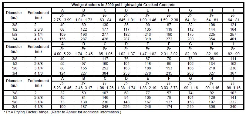
34 National Fire Protection Association Report 10 of /7/ :51 PM Diameter Diameter Embedment Embedment A B C D E F G H I A B C D E F G H I Pr Pr Pr Diameter Embedment Pr Pr Pr Pr Pr A B C D E F G H I Pr Pr Pr Pr Pr * Pr = prying factor range. (Refer to A for additional information.) Table (b) Wedge Anchors in 3000 psi Lightweight Cracked Concrete Diameter Diameter Embedment Pr Pr Pr A B C D E F G H I Pr Pr Pr Pr Pr Pr Pr Pr Pr Pr Pr Embedment A B C D E F G H I Diameter Pr Pr Pr Pr Pr Pr Pr Pr Pr Embedment A B C D E F G H I Pr Pr Pr Pr Pr Pr Pr Pr Pr * Pr = prying factor range. (Refer to A for additional information.) Table (c) Wedge Anchors in 3000 psi Normal Weight Cracked Concrete Diameter Diameter Embedment A B C D E F G H I Pr Pr Pr Pr Pr Pr Pr Pr Pr Embedment A B C D E F G H I Pr Pr Pr Pr Pr Pr Pr Pr Pr
35 National Fire Protection Association Report 11 of /7/ :51 PM Diameter Embedment A B C D E F G H I Diameter Embedment A B C D E F G H I Pr Pr Pr Pr Pr Pr Pr Pr * Pr = prying factor range. (Refer to A for additional information.) Table (d) Wedge Anchors in 4000 psi Normal Weight Cracked Concrete Diameter Embedment A B C D E F G H I Pr Pr Pr Pr Pr Pr Pr Pr Pr Pr Diameter Embedment A B C D E F G H I Pr Pr Pr Pr Pr Pr Pr Pr Pr Diameter Embedment A B C D E F G H I Pr Pr Pr Pr Pr Pr Pr Pr Pr * Pr = prying factor range. (Refer to A for additional information.) Table (e) Wedge Anchors in 6000 psi Normal Weight Cracked Concrete Diameter Embedment A B C D E F G H I Pr Pr Pr Pr Pr Pr Pr Pr Pr Diameter Embedment A B C D E F G H I Pr Pr Pr Pr Pr Pr Pr Pr Pr Diameter Embedment A B C D E F G H I Pr Pr Pr Pr Pr Pr Pr Pr Pr
36 National Fire Protection Association Report 12 of /7/ :51 PM Diameter Embedment A B C D E F G H I * Pr = prying factor range. (Refer to A for additional information.) Table (f) Undercut Anchors in 3000 psi Normal Weight Concrete Diameter Embedment A B C D E F G H I Table (g) Connections to Steel (Values Assume Bolt Perpendicular to Mounting Surface) Diameter of Unfinished Steel Bolt A B C D E F G H I A B C D E F G H I Diameter of Unfinished Steel Bolt A B C D E F G H I A B C D E F G H I Table (h) Through-Bolts in Sawn Lumber or Glue-Laminated Timbers (Load Perpendicular to Grain) Bolt Diameter Length of Bolt in Timber A B C D E F G H I A B C D E F G H I A B C D E F G H I Table (i) Lag Screw and Lag Bolts in Wood (Load Perpendicular to Grain Holes Predrilled Using Good Practice) Lag Bolt Diameter Length of 4 1 Bolt 2 in 5 Timber A B C D E F G H I A B C D E F G H I A B C D E F G H I Table (j) Specific Gravity Multiplier Specific Gravity of Wood Multiplier 0.36 thru thru thru /2 Note: Wood fastener maximum capacity values are based on 2001 National Design Specifications (NDS) for wood with a specific gravity of Values for other types of wood can be obtained by multiplying the values given in Table (f) through Table (i) by the factors given in this table.
37 National Fire Protection Association Report 13 of /7/ :51 PM The type of fasteners used to secure the bracing assembly to the structure shall be limited to those shown in Figure (a), Figure (b), and Table (a) through Table (j) or to listed devices * For connections to wood, through-bolts with washers on each end shall be used, unless the requirements of are met Where it is not practical to install through-bolts due to the thickness of the wood member in excess of 12 in. (305 mm) or inaccessibility, lag screws shall be permitted and holes shall be pre-drilled 1 8 in. (3.2 mm) smaller than the maximum root diameter of the lag screw Holes for through-bolts and similar listed attachments shall be 1 16 in. (1.6 mm) greater than the diameter of the bolt The requirements of shall not apply to other fastening methods, which shall be acceptable for use if certified by a registered professional engineer to support the loads determined in accordance with the criteria in Calculations shall be submitted where required by the authority having jurisdiction Concrete Anchors * Concrete anchors shall be prequalified for seismic applications in accordance with ACI 355.2, Qualification of Post-Installed Mechanical Anchors in Concrete and Commentary, and installed in accordance with the manufacturer's instructions Concrete anchors other than those shown in Figure shall be acceptable for use where designed in accordance with the requirements of the building code and certified by a registered professional engineer. Allowable concrete anchor loads shall be determined based upon the prying factor associated with the specific upper seismic brace attachment fitting to the structure. (A) Sway brace manufacturers shall provide prying factors based on geometry of the fitting and the brace orientation angles A through I as shown in Figure (a), Figure (b), and Table (a) through Table (j) For each brace orientation angle range, the prying factor shall be taken as the largest value associated with the minimum and maximum angles within that range. (A) Where the prying factor for the fitting is unknown, the largest prying factor value in Figure (a), Figure (b), and Table (a) through Table (j) for the specific condition based on the brace angle A through I shall be used Concrete anchors other than those shown in Figure (a), Figure (b), and Table (a) through Table (j) shall be acceptable for use where designed in accordance with the requirements of the building code and certified by a registered professional engineer. Supplemental Information File Name Tables_ _f_through_j.pdf Wedge_Anchor_Tables.docx 13_SR_15_Table_ _f_.docx 13_SR_15_Table_ _g_.docx 13_SR_15_Table_ _h_.docx 13_SR_15_Table_ _i_.docx 13_SR_15_Table_ _j_.docx 13_SR_15_A_9_3_5_12_edited_REV_MJK_.docx 13_SR_15_Tables_ _a_b_and_c_.xlsx 13_SR_15_Table_ _d_.xlsx 13_SR_15_Table_ _e_.xlsx Description Tables (a) through (e) Submitter Information Verification Submitter Full Name: [ Not Specified ] Organization: [ Not Specified ] Street Address: City:
38 National Fire Protection Association Report 14 of /7/ :51 PM State: Zip: Submittal Date: Sun Jun 22 18:05:56 EDT 2014 Committee Statement Committee Statement: The building code references ASCE/SEI 7-10 Minimum Design Loads for Buildings and Other Structures for structural design criteria. NFPA 13 is adopted as a reference standard by ASCE/SEI 7-10, and the seismic design provisions of NFPA 13 have are deemed to comply with the requirements of ASCE/SEI This is a great advantage, because it means the designs per NFPA 13 may be accepted by building officials as completely code compliant. To maintain this status, the seismic provisions of NFPA 13 must be periodically reexamined to verify that changes in ASCE/SEI 7 are accounted for in NFPA 13. This proposal is the first significant revision to the NFPA 13 requirements for concrete anchors since the 2007 edition. It accounts for significant changes in the design of attachment for nonstructural components that were adopted with Supplement 1 of ASCE/SEI 7-10 in The most significant change is the requirement that loads for attachment of nonstructural components to concrete or masonry be amplified by a factor of 2.5. In addition, the load factor used in NFPA 13 for converting from strength design to allowable stress design forces required updating. Finally, the current allowable loads for concrete anchors do not correctly account for a load factor for attachments of 1.3 that was required in ASC/SEI 7-05, which has been increased to 2.5 as noted above. Addressing these issues results in substantially lower allowable load carrying capacities of the concrete anchors in the Fig Tables but it must be done in order to insure that NFPA 13 preserves its standing as a code-compliant Standard. To mitigate the effects of these changes, a more refined design approach is offered, that allows the user to take advantage of connection hardware with favorable geometry, which reduces the prying factor applied to tension loads. In prior editions of NFPA 13, a worst-case prying factor was assumed when generating the allowable loads in Figure In this proposal, allowable anchor loads are provided for three ranges of prying factors. By selecting of efficient connection hardware, the allowable anchor loads can be substantially increased. The proposal includes the following changes: Section 2.3.2: Updates the references to the latest edition of ASCE 7. Section 3.11: Adds a definition of prying factor. Section : Specifically permits an engineer to come up with their own allowable anchor loads. Given that Fig uses lower bound assumptions for the allowable anchor tension and shear capacities and conservative assumptions regarding brace and connection geometry, an engineered design for the anchors may yield substantially higher allowable loads. Section : Adds procedures for using the revised Fig Revisions to Figure New tables for wedge anchor allowable loads in different types of concrete conditions. Revision to Annex A : Expanded and corrected coverage of the anchor allowable load provisions New Annex E.7: Provides step by step procedures and examples for determining allowable loads for wedge anchors, shows how the generic Fig concrete anchor table values were calculated, and provides instruction to the user for performing specific calculations that may yield more beneficial results. Revised Fig anchor tables and related annex information were unanimously passed at the 2016 NFPA-13 2nd Draft Meeting. Response Message: Public Comment No. 298-NFPA [Section No ]
39
")
40 Table (a) Table (b)
 1 (d)")
41 Table (c) Table (d)

42 Table (e)
43 Undercut Anchors in 3000 psi Normal Weight Concrete Diameter Embedment A B C D E F G H I 3/ ½ /8 7 1/
44 Connections to Steel (Values Assume Bolt Perpendicular to Mounting Surface) Diameter of Unfinished Steel Bolt 1/4 3/8 A B C D E F G H I A B C D E F G H I Diameter of Unfinished Steel Bolt 1/2 5/8 A B C D E F G H I A B C D E F G H I
45 Length of Bolt in Timber (in). Through Bolts in Saw Lumber or Glue Laminated Timbers (Load Perpendicular to Grain) Bolt Diameter 1/2 5/8 3/4 A B C D E F G H I A B C D E F G H I A B C D E F G H I 1 ½ ½ ½ ½
46 Length of Bolt in Timber Lag Screw and Lag Bolts in Wood (Load Perpendicular to Grain Holes Predrilled Using Good Practice) Lag Bolt Diameter 3/8 1/2 5/8 A B C D E F G H I A B C D E F G H I A B C D E F G H I 3 ½ ½ ½ ½
47 Specific Gravity of Wood Multiplier 0.36 thru thru thru
48 A Current fasteners for anchoring to concrete are referred to as post installed anchors. There are several types of post installed anchors, including expansion anchors, chemical or adhesive anchors, and undercut anchors. The criteria in Figure (a) and Figure (b) and Table (a) through Table (j) are based on the use of wedge expansion anchors and undercut anchors. Use of other anchors in concrete should be in accordance with the listing provisions of the anchor. Anchorage designs are usable under ASD methods. Values in Table (a) through Table (j) are based on an 8 to 1 safety factor in tension and a 4 to 1 safety factor in shear for allowable loads ultimate strength design values obtained using the procedures in Annex D of ACI 318, Building Code Requirements for Structural Concrete and Commentary, which are then adjusted for allowable stress design. Wedge anchors are torque controlled expansion anchors that are set by applying a torque to the anchor s nut, which causes the anchor to rise while the wedge stays in place. This causes the wedge to be pulled onto a coned section of Formatted: Not Highlight Formatted: Not Highlight Formatted: Not Highlight
49 the anchor and presses the wedge against the wall of the hole. Undercut anchors might or might not be torque controlled. Typically, the main hole is drilled, a special second drill bit is inserted into the hole, and flare is drilled at the base of the main hole. Some anchors are self drilling and do not require a second drill bit. The anchor is then inserted into the hole and, when torque is applied, the bottom of the anchor flares out into the flared hole, and a mechanical lock is obtained. Consideration should be given with respect to the position near the edge of a slab and the pacing of anchors. Typically ffor full capacity in Figure (a) and Figure (b) and Table (a) through Table (j), the edge distance, should be mes the embedment and 3 times the embedment for the spacing between anchors, and the thickness of concrete should conform to the anchor manufacturer s recommendations. COMP: Replace Section A with the following (retain all figures):
50 A The values for the wedge anchor tables and the undercut anchor tables have been developed using the following formula: 1.2 COMP: Add equation number [A a] COMP: Please make the allow in two places in the above equation subscript. where: T = applied service tension load including the effect of prying (Fpw x Pr) Fpw = horizontal earthquake load Pr = prying factor based on fitting geometry and brace angle from vertical Tallow = allowable service tension load V = applied service shear load Vallow = allowable service shear load T/Tallow should not exceed 1.0. V/Vallow should not exceed 1.0.
51 The allowable tension and shear loads come from the anchor manufacturer s published data. As required in Supplement 1 of ASCE/SEI 7, Minimum Design Loads for Buildings and Other Structures, the design loads have been amplified by an overstrength factor of 2.5, and the allowable strength of the anchors has been increased by a factor of 1.2. As the effect of prying on the applied tension is also to develop appropriate load values, the applied tension equation, including the prying effect, varies with the orientation of the fastener in relationship to the brace necessary at various brace angles. The letters A through D in the following equations are the dimensions of the anchors as indicated in Figure A (a) through Figure A (c). where: Cr = critical angle at which prying flips to the toe or the heel of the structure attachment fitting Pr = prying factor for service tension load effect of prying TanӨ = tangent of brace angle from vertical For anchor orientations A, B, and C, the applied tension, including the effect of prying (Pr), is as follows: [A b]
52 For braces acting in tension, Cr < brace angle from vertical is as follows: / [A c] ϴ Cr > Brace angle from vertical is as follows: [A d] ϴ / For braces acting in compression, Cr < brace angle from vertical is as follows: / [A e] ϴ Cr > brace angle from vertical is as follows: / [A f] ϴ
53 For anchor orientations D, E, and F, the applied tension, including the effect of prying (Pr), is as follows: For braces acting in tension, [A g] Cr < brace angle from vertical is as follows: / [A h] ϴ Cr > brace angle from vertical is as follows: [A i] / For braces acting in compression, Formatted: Font: Italic Cr < brace angle from vertical is as follows: / [A j] ϴ Cr > brace angle from vertical is as follows: / [A k] ϴ
54 For anchor orientations G, H, and I the applied tension, including the effect of prying (Pr), is as follows: [A l]
55 Table (a) Diameter Embedment Wedge Anchors in 3000 psi Sand Lightweight Cracked Concrete on Metal Deck A B C D E F G H I Pr Pr Pr Pr Pr Pr Pr Pr Pr / /2 2 3/ /8 3 1/ Diameter Embedment A B C D E F G H I Pr Pr Pr Pr Pr Pr Pr Pr Pr / /2 2 3/ /8 3 1/ Diameter Embedment A B C D E F G H I Pr Pr Pr Pr Pr Pr Pr Pr Pr / /2 2 3/ /8 3 1/ Table (b) Diameter Embedment Wedge Anchors in 3000 psi Lightweight Cracked Concrete A B C D E F G H I Pr Pr Pr Pr Pr Pr Pr Pr Pr / /2 2 3/ /8 3 1/ /4 4 1/ Diameter Embedment A B C D E F G H I Pr Pr Pr Pr Pr Pr Pr Pr Pr / /2 2 3/ /8 3 1/ /4 4 1/ Diameter Embedment A B C D E F G H I Pr Pr Pr Pr Pr Pr Pr Pr Pr / /2 2 3/ /8 3 1/ /4 4 1/ Table (c) Diameter Embedment Wedge Anchors in 3000 psi Normal Weight Cracked Concrete A B C D E F G H I Pr Pr Pr Pr Pr Pr Pr Pr Pr / /2 3 5/ /8 3 7/ /4 4 1/ Diameter Embedment A B C D E F G H I Pr Pr Pr Pr Pr Pr Pr Pr Pr / /2 3 5/ /8 3 7/ /4 4 1/ Diameter Embedment A B C D E F G H I Pr Pr Pr Pr Pr Pr Pr Pr Pr / /2 3 5/ /8 3 7/ /4 4 1/
56 Table (d) Wedge Anchors in 4000 psi Normal Weight Cracked Concrete Diameter Embedment A B C D E F G H I Pr Pr Pr Pr Pr Pr Pr Pr Pr / /2 3 5/ /8 3 7/ /4 4 1/ Diameter A B C D E F G H I Pr Pr Pr Pr Pr Pr Pr Pr Pr 3/ /2 3 5/ /8 3 7/ /4 4 1/ A B C D E F G H I Diameter Embedment Embedment Pr Pr Pr Pr Pr Pr Pr Pr Pr 3/ /2 3 5/ /8 3 7/ /4 4 1/ * Pr = prying factor range. (Refer to Annex for additional information.)
57 Table (e) Wedge Anchors in 6000 psi Normal Weight Cracked Concrete Diameter Embedment A B C D E F G H I Pr Pr Pr Pr Pr Pr Pr Pr Pr /8 2 1/ /2 3 5/ /8 3 7/ /4 4 1/ Diameter A B C D E F G H I Pr Pr Pr Pr Pr Pr Pr Pr Pr 3/8 2 1/ /2 3 5/ /8 3 7/ /4 4 1/ A B C D E F G H I Diameter Embedment Embedment Pr Pr Pr Pr Pr Pr Pr Pr Pr 3/8 2 1/ /2 3 5/ /8 3 7/ /4 4 1/ ctor range. (Refer to Annex for additional information.)
58 National Fire Protection Association Report 15 of /7/ :51 PM Second Revision No. 17-NFPA [ Section No ] * Branch lines shall be laterally restrained at intervals not exceeding those specified in Table (a) or Table (b) based on branch line diameter and the value of C p. Table (a) Maximum Spacing (ft), of Steel Pipe Restraints Seismic Coefficient, C p Pipe C p < C p < C P 1.40 C P Note: For SI values, 1 in = 25.4 mm Table (b) Maximum Spacing (ft), of CPVC, Copper, and Copper Pipe Red Brass Pipe Restraints Seismic Coefficient C p Pipe C p < C p < C P 1.40 C P Note: For SI values, 1 in in. = 25.4 mm mm. Submitter Information Verification Submitter Full Name: [ Not Specified ] Organization: [ Not Specified ] Street Address: City: State: Zip: Submittal Date: Sun Jun 22 19:01:41 EDT 2014 Committee Statement Committee Statement: This change adds red brass piping to the revised table for branch line restraints. Response Message:
59 National Fire Protection Association Report 16 of /7/ :51 PM Second Revision No. 12-NFPA [ Section No ] 9.3.8* Pipe Stands Subject to Earthquakes In areas where the horizontal force factor exceeds 0.5 W p, pipe stands over 4 ft (1.2 m) in height shall be certified by a registered professional engineer to be adequate for the seismic forces Where seismic protection is provided, concrete anchors used to secure pipe stands to their base bases shall be in accordance with ACI 355.2, Qualification of Post-Installed Mechanical Anchors in Concrete and Commentary, and shall be installed in accordance with manufacturer s instructions Pipe saddles shall not be used to attach the system piping to the pipe stand. Submitter Information Verification Submitter Full Name: [ Not Specified ] Organization: [ Not Specified ] Street Address: City: State: Zip: Submittal Date: Sun Jun 22 17:27:15 EDT 2014 Committee Statement Committee Statement: This revision was created to correlate with the revisions in SR-11 regarding pipe stand installations. Response Message:
60 National Fire Protection Association Report 83 of /7/ :51 PM Second Revision No. 151-NFPA [ Section No. A (1) ]
61 National Fire Protection Association Report 84 of /7/ :51 PM A (1)
62 National Fire Protection Association Report 85 of /7/ :51 PM Figure A (1)(a) and Figure A (1)(b) are examples of how to measure the distance between the top of pipe and the point of attachment. Figure A (1)(a) Measurement for Distance Between Top of Pipe and Point of Attachment (Example 1). Figure A (1)(b) Measurement for Distance Between Top of Pipe and Point of Attachment (Example 2).

63 National Fire Protection Association Report 86 of /7/ :51 PM Supplemental Information File Name rod_rule_revised-wood pdf rod_rule_revised-steel pdf Description Submitter Information Verification Submitter Full Name: Matthew Klaus Organization: National Fire Protection Assoc Street Address:
KINETICS Pipe & Duct Seismic Application Manual
 KINETICS ipe & Duct Seismic Application Manual FIRE ROTECTION IING SYSTEMS S13.1 Introduction: Historically the ICC (2000, 2003, 2006, and 2009 IBC) and the NFA (NFA 5000) have been competing code writing
HANGERS AND SUPPORTS FOR HVAC PIPING AND EQUIPMENT SECTION HANGERS AND SUPPORTS FOR HVAC PIPING AND EQUIPMENT
 13686.00 HANGERS AND SUPPORTS FOR HVAC PIPING AND EQUIPMENT 230529-1 SECTION 230529 - HANGERS AND SUPPORTS FOR HVAC PIPING AND EQUIPMENT 1.1 SUMMARY A. Section Includes: 1. Metal pipe hangers and supports.
SECTION HANGERS AND SUPPORTS FOR PLUMBING
 SECTION 22 05 29 HANGERS AND SUPPORTS FOR PLUMBING PART 1 - GENERAL 1.1 RELATED DOCUMENTS A. Drawings and general provisions of the Contract, including General and Supplementary Conditions and Division
Fig Beam Clamp Retaining Strap (B-Line B3367)
") Fig. 69 - Beam Clamp Retaining Strap (B-Line B3367) Size Range: 3 /8"-16 thru 3 /4"-10 rod 4 (101.6mm) thru 16 (406.4mm) lengths Note: longer lengths are available consult factory Material: Pre-Galvanized
Fig. 69 - Beam Clamp Retaining Strap (B-Line B3367) Size Range: 3 /8"-16 thru 3 /4"-10 rod 4 (101.6mm) thru 16 (406.4mm) lengths Note: longer lengths are available consult factory Material: Pre-Galvanized
DIVISION 15-MECHANICAL SECTION SUPPORTS AND ANCHORS PN PART 1 - GENERAL 1.01 SECTION INCLUDES. A. Pipe and equipment support systems.
 PART 1 - GENERAL 1.01 SECTION INCLUDES A. Pipe and equipment support systems. B. Inserts. 1.02 RELATED SECTIONS A. Section 15890 - Ductwork Supports. 1.03 DEFINITIONS A. Supports: Attachments, hangers,
SECTION HANGERS AND SUPPORTS FOR PLUMBING PIPING AND EQUIPMENT
 Page 220529-1 SECTION 220529 - PART 1 - GENERAL 1.1 RELATED DOCUMENTS A. Drawings and general provisions of the Contract, including General and Supplementary Conditions and Division 01 Specification Sections,
SECTION VIBRATION CONTROLS FOR HVAC PIPING AND EQUIPMENT
 SECTION 230548 - PART 1 - GENERAL 1.1 SUMMARY A. This Section includes the following: 1. Elastomeric Isolation pads. 2. Elastomeric Isolation mounts. 3. [Freestanding] [Restrained] [Freestanding and restrained]
OSU PROJECT NO PAGE 1 02 NOV 2006 SECTION SUPPORTS AND ANCHORS
 OSU PROJECT NO. 30-04-15 PAGE 1 PART 1 GENERAL 1.1 WORK INCLUDED A. Supports and anchors for piping systems and equipment. 1.2 RELATED WORK SPECIFIED ELSEWHERE A. The provisions of Section 15050, Basic
SECTION HANGERS AND SUPPORTS FOR PLUMBING PIPING AND EQUIPMENT
 SECTION 220529 - HANGERS AND SUPPORTS FOR PLUMBING PIPING AND EQUIPMENT PART 1 - GENERAL 1.1 DESCRIPTION A. The General Conditions, Special Conditions and Division 1 through Division 22 as set forth in
NORTH HARRIS COUNTY REGIONAL WATER AUTHORITY PIPE HANGERS, Section PIPE HANGERS, SUPPORTS, AND RESTRAINTS
 PART 1 GENERAL 1.01 SUMMARY Section 15140 PIPE HANGERS, This Section includes the furnishing and subsequent installation of: A. Pipe and equipment hangers, supports, and associated anchors B. Equipment
SECTION HANGERS AND SUPPORTS FOR PLUMBING PIPING AND EQUIPMENT
 SECTION 220529 HANGERS AND SUPPORTS FOR PLUMBING PIPING AND EQUIPMENT PART 1 - GENERAL 1.1 RELATED DOCUMENTS A. Drawings and general provisions of the Contract, including General and Supplementary Conditions
NORTHWESTERN UNIVERSITY PROJECT NAME JOB #
 SECTION 26 0529 - HANGERS AND SUPPORTS FOR ELECTRICAL SYSTEMS PART 1 - GENERAL 1.1 RELATED DOCUMENTS A. Drawings and general provisions of the Contract, including General and Supplementary Conditions and
SECTION SEISMIC CONTROL OSHPD
 SECTION 01451 PART 1 - GENERAL 1.01 DESCRIPTION A. Provide all required seismic restraints and calculations in order to insure that the installation of all architectural, mechanical, and electrical equipment/components
DARTMOUTH COLLEGE DESIGN September 15, 2004 &CONSTRUCTION GUIDELINES
 PART 1 DESIGN DIRECTIVE 1.1 RELATED DOCUMENTS SECTION 15240 SEISMIC RESTRAINT AND VIBRATION CONTROL A. This section shall be considered as a part of each DC Standards, Part 15. 1.2 QUALITY ASSURANCE A.
1.2 ACTION AND INFORMATIONAL SUBMITTALS.1 Provide submittals in accordance with Section Submittal Procedures.
 BID OPPORTUNITY NO. 253-2011 PAGE 1 OF 7 PART 1 GENERAL 1.1 REFERENCES.1 American Society of Mechanical Engineers (ASME).1 ASME B31.1, Power Piping, B31.3 Process Piping, B31.9 Building Services Piping..2
Daytona Beach Pier Building Renovation Jun 2010
 SECTION 15060 - HANGERS AND SUPPORTS PART 1 - GENERAL 1.1 RELATED DOCUMENTS A. Drawings and general provisions of the Contract, including General and Supplementary Conditions and Division 1 Specification
1. Hangers and supports for electrical equipment and systems. 2. Construction requirements for concrete bases.
 SECTION 260529 - HANGERS AND SUPPORTS PART 1 - GENERAL 1.1 SUMMARY A. Section includes: 1. Hangers and supports for electrical equipment and systems. 2. Construction requirements for concrete bases. 1.2
SEISMIC RESTRAINTS Multi-Directional Bracing For Electrical Conduit, Cable Tray And Mechanical Piping Systems
 SEISMIC RESTRAINTS Multi-Directional Bracing For Electrical Conduit, Cable Tray And Mechanical Piping Systems SYSTEMS THAT MAKE SENSE INTRODUCTION INTRODUCTION What is Seismic Bracing? Seismic forces are
SECTION VIBRATION AND SEISMIC CONTROLS FOR ELECTRICAL SYSTEMS
 PART 1 - GENERAL 1.1 RELATED DOCUMENTS A. Drawings and general provisions of the Contract, including General and Supplementary Conditions, apply to this Section. 1.2 SUMMARY A. This Section includes the
SECTION HANGERS AND SUPPORTS FOR PLUMBING PIPING AND EQUIPMENT
 SECTION 220529 - PART 1 - GENERAL 1.1 SUMMARY A. This Section includes the following: 1. Steel pipe hangers and supports. 2. Metal framing systems. 3. Thermal-hanger shield inserts. 4. Fastener systems.
A. Pipe Supports: ANSI B 31.1, Power Piping. B. Automatic Sprinkler Pipe Supports: Refer to Section
 SECTION 15140 SUPPORTS, ANCHORS, AND SEALS PART 1 - GENERAL 1.01 RELATED DOCUMENTS A. Drawings and general provisions of Contract including General and Supplementary Conditions, Division 1 Specification
Fig. 1 - Standard Clevis Hanger
 Revision 10/24/2007 Fig. 1 - Standard Clevis Hanger Component of State of California OSHPD Approved Seismic Restraints System Size Range Size 1/2" thru 36" pipe. Function Recommended for the suspension
SECTION HANGERS AND SUPPORTS FOR PLUMBING PIPING AND EQUIPMENT. A. ASME B31.1 (American Society of Mechanical Engineers) - Power Piping
 - Power Piping") SECTION 22 05 29 HANGERS AND SUPPORTS FOR PLUMBING PIPING AND EQUIPMENT PART 1 - GENERAL 1.1 SUMMARY A. Section includes pipe and equipment supports, hangers, anchors, bases sleeves and the sealing of
SECTION 22 05 29 HANGERS AND SUPPORTS FOR PLUMBING PIPING AND EQUIPMENT PART 1 - GENERAL 1.1 SUMMARY A. Section includes pipe and equipment supports, hangers, anchors, bases sleeves and the sealing of
SECTION HANGERS AND SUPPORTS FOR HVAC PIPING AND EQUIPMENT
 SECTION 23 05 29 HANGERS AND SUPPORTS FOR HVAC PIPING AND EQUIPMENT PART 1 - GENERAL 1.1 SUMMARY A. Section includes pipe and equipment supports, hangers, anchors, bases sleeves and the sealing of work
SECTION HANGERS AND SUPPORTS FOR HVAC PIPING AND EQUIPMENT
 SECTION 230529 - HVAC PIPING AND EQUIPMENT PART 1 - GENERAL 1.1 RELATED DOCUMENTS A. Drawings and General Provisions of Contract, including General Conditions and other Division 1 Specification Sections,
SECTION HANGERS AND SUPPORTS PART 1 - GENERAL. A. Drawings and Division 1 Specification Sections, apply to this Section.
 1.01 RELATED DOCUMENTS SECTION 15060 HANGERS AND SUPPORTS PART 1 - GENERAL A. Drawings and Division 1 Specification Sections, apply to this Section. 1.02 SUMMARY A. This Section includes hangers and supports
Updated references to SEI/ASCE 7 to the 2016 edition once it is available.
 Committee Input No. 8008-NFPA 5000-2015 [ Global Input ] Updated references to SEI/ASCE 7 to the 2016 edition once it is available. Submitter Information Verification Submitter Full Name: Tracy Vecchiarelli
Seismic Restraints. Cent-R-Rail Supplement* SYSTEMS THAT MAKE SENSE
 SRSCR-0 Seismic Restraints Cent-R-Rail Supplement* Multi-Directional Bracing For Data-Track, Half-Rack and Multi-Tier Half-Rack Systems Structural Engineer S 9 *To be used in conjunction with Cooper B-Line
NORTHWESTERN UNIVERSITY PROJECT NAME JOB # ISSUED: 03/29/2017
 SECTION 23 0529 - MECHANICAL SUPPORTING DEVICES PART 1 - GENERAL 1.1 RELATED DOCUMENTS A. Drawings and general provisions of the Contract, including General and Supplementary Conditions and Division 01
Interior Hangers. Application
 Application Interior bridge deck hangers are typically fabricated using two heavy duty sheet metal end clips that have been electrically resistance welded to an appropriate sized wire or formed metal connecting
City of Winnipeg BASES, HANGERS AND SUPPORTS Section NEWPCC - Pump Well Isolation Page 1 of 6 Tender No June 2003
 NEWPCC - Pump Well Isolation Page 1 of 6 PART 1 General 1.1 RELATED SECTIONS.1 Section 01001 General Requirements..2 Section 03300 - Cast-in-Place Concrete..3 Section 05121 - Structural Steel for Buildings..4
SECTION HANGERS AND SUPPORTS FOR HVAC PIPING AND EQUIPMENT
 SECTION 230529 - HANGERS AND SUPPORTS FOR HVAC PIPING AND EQUIPMENT PART 1 - GENERAL 1.1 RELATED DOCUMENTS A. Drawings and general provisions of the Contract, including General and Supplementary Conditions
SECTION HANGERS AND SUPPORTS FOR ELECTRICAL SYSTEMS
 SECTION 26 05 29 HANGERS AND SUPPORTS FOR ELECTRICAL SYSTEMS PART 1 GENERAL 1.1 DESCRIPTION A. Scope: 1. CONTRACTOR shall provide all labor, materials, equipment, and incidentals as shown, specified, and
SECTION HANGERS AND SUPPORTS FOR PLUMBING PIPING AND EQUIPMENT
 SECTION 22 0529 HANGERS AND SUPPORTS FOR PLUMBING PIPING AND EQUIPMENT PART 1 - GENERAL 1.1 RELATED DOCUMENTS A. Drawings and general provisions of the Contract, including General and Supplementary Conditions
Anchor bolts ASTM F1554, Gr. 36 Wide flange beams ASTM A992, Fy = 50 ksi Misc. structural steel ASTM A36, Fy = 36 ksi
 STRUCTURAL NOTES MATERIAL STRENGTHS Structural Steel Reinforcing Steel Concrete Masonry Structural Lumber Anchor bolts ASTM F1554, Gr. 36 Wide flange beams ASTM A992, Fy = 50 ksi Misc. structural steel
REPORT HOLDER: MITEK USA, INC. (FORMERLY USP STRUCTURAL CONNECTORS) SOUTHCROSS DRIVE, SUITE 200 BURNSVILLE, MINNESOTA EVALUATION SUBJECT:
 SOUTHCROSS DRIVE, SUITE 200 BURNSVILLE, MINNESOTA EVALUATION SUBJECT:") 0 Most Widely Accepted and Trusted ICC ES Evaluation Report ICC ES 000 (800) 43 6587 (56) 699 0543 www.icc es.org ESR 3754 Reissued 09/07 This report is subject to renewal 09/09. DIVISION: 03 00 00 CONCRETE
0 Most Widely Accepted and Trusted ICC ES Evaluation Report ICC ES 000 (800) 43 6587 (56) 699 0543 www.icc es.org ESR 3754 Reissued 09/07 This report is subject to renewal 09/09. DIVISION: 03 00 00 CONCRETE
FIGURE R502.2 FLOOR CONSTRUCTION
 CHAPTER 5 FLOORS 11 I SECTION R501 GENERAL R501.1 Application. The provisions of this chapter shall control the design and construction of the floors for all buildings including the floors of attic spaces
Union County Vocational - Technical Schools Scotch Plains, New Jersey
 SECTION 055113 - METAL PAN STAIRS PART 1 - GENERAL 1.1 RELATED DOCUMENTS A. Drawings and general provisions of the Contract, including General and Supplementary Conditions and Division 01 Specification
TOLCO Fire Protection Support Systems. Pipe Hangers Supports Seismic Bracing. UL Listed FM Approved for Fire Sprinkler Installations
 TOLCO Fire Protection Support Systems Pipe Hangers Supports Seismic Bracing UL Listed FM Approved for Fire Sprinkler Installations Revision 12/06/2007 Catalog Forward This catalog has been created with
UNIVERSITY SERVICES ANNEX James Madison University Harrisonburg, Virginia State Project Code: Architect s Project Number:
 SECTION 230529 - HANGERS AND SUPPORTS FOR HVAC PIPING AND EQUIPMENT PART 1 - GENERAL 1.1 RELATED DOCUMENTS A. Provisions of the Contract and of the Contract Documents apply to this Section. 1.2 DEFINITIONS
Sprinkler Identification Numbers (SINs)
") Worldwide Contacts www.tyco-fire.com Model 2.8 K-factor Combustible Concealed Space Sprinklers Specific Application, Upright General Description The Model Combustible Concealed Sprinklers are fast response,
Worldwide Contacts www.tyco-fire.com Model 2.8 K-factor Combustible Concealed Space Sprinklers Specific Application, Upright General Description The Model Combustible Concealed Sprinklers are fast response,
SECTION PLATE CONNECTED WOOD TRUSSES
 SECTION 06173 PLATE CONNECTED WOOD TRUSSES PART 1 GENERAL 1.01 SUMMARY A. Section Includes: 1. Shop fabricated wood trusses for roof and floor framing. 2. Bridging, bracing, and anchorage. B. Related Sections:
INTERNATIONAL ASSOCIATION OF PLUMBING AND MECHANICAL OFFICIALS UNIFORM EVALUATION SERVICE EVALUATION CRITERIA FOR
 INTERNATIONAL ASSOCIATION OF PLUMBING AND MECHANICAL OFFICIALS UNIFORM EVALUATION SERVICE EVALUATION CRITERIA FOR HELICAL PILES FOR USE UNDER THE INTERNATIONAL RESIDENTIAL CODE EC027-2017 (Adopted November
POST FRAME BUILDING STANDARDS
 CASS COUNTY, MISSOURI BUILDING CODES, ENVIRONMENTAL HEALTH AND ZONING DEPARTMENT 30508 S. West Outer Road, Harrisonville, MO 64701 P- (816) 380-8134 F- (816) 380-8130 POST FRAME BUILDING STANDARDS 201.3
DIVISION: EARTHWORK SECTION: BORED PILES REPORT HOLDER: GEOTECH ENTERPRISES, INC.
 0 Most Widely Accepted and Trusted ICC ES Report ICC ES 000 (800) 423 6587 (562) 699 0543 www.icc es.org ESR 3623 Reissued 04/2017 This report is subject to renewal 04/2018. DIVISION: 31 00 00 EARTHWORK
CH. 9 WOOD CONSTRUCTION
 CH. 9 WOOD CONSTRUCTION PROPERTIES OF STRUCTURAL LUMBER Grading Load carrying capacity effected by: - Size and number of knots, splits & other defects - Direction of grain - Specific gravity of wood Grading
SPECIFICATIONS - DETAILED PROVISIONS Section Stainless Steel Sluice Gates C O N T E N T S
 SPECIFICATIONS - DETAILED PROVISIONS Section 11294 - Stainless Steel Sluice Gates C O N T E N T S PART 1 - GENERAL... 1 1.01 SUMMARY... 1 1.02 REFERENCES... 1 1.03 DEFINITIONS... 1 1.04 DESIGN REQUIREMENTS...
HILLSBOROUGH TOWNSHIP CODE ENFORCEMENT
 HILLSBOROUGH TOWNSHIP CODE ENFORCEMENT SAMPLE GUIDE FOR RESIDENTIAL DECKS revised 7 16 Call before you dig! 1 800 272 1000 New Jersey One Call. Utility Mark Out. THIS GENERIC GUIDE IS NOT ALL INCLUSIVE
a difficult challenge when trying to achieve effective coverage within a shallow space. The Model CC1 Combustible
 Worldwide Contacts www.tyco-fire.com Model CC1 2.8 K-factor Combustible Concealed Space Sprinklers Specific Application, Upright General Description The Model CC1 Combustible Concealed Sprinklers are fast
HANGERS AND SUPPORTS FOR HVAC PIPING AND EQUIPMENT
 SECTION 23 05 29 PART 1 - GENERAL 1.01 RELATED DOCUMENTS A. Drawings and general provisions of the Contract, including General and Supplementary Conditions and Division 1 Specification Sections, apply
Seismic Installation Manual
 Seismic Installation Manual California Office of Statewide Health Planning & Development OPA-2123-10 This manual provides the design strength capacities and installation guidelines for the Bracing System
SECTION METAL FLOOR PLATE STAIRS
 SECTION 05513 - METAL FLOOR PLATE STAIRS PART 1 - GENERAL 1.1 RELATED DOCUMENTS A. Drawings and general provisions of the Contract, including General and Supplementary Conditions and Division 01 Specification
SPECIFICATIONS FOR THE CONSTRUCTION OF NEW PASSENGER EQUIPMENT CARS PREFACE
 SPECIFICATIONS FOR THE CONSTRUCTION OF NEW PASSENGER EQUIPMENT CARS Standard ADOPTED 1939; ADVANCED TO STANDARD, 1945. PREFACE The specifications have been prepared on the basis that they will be used
REPORT HOLDER: MITEK USA, INC. (FORMERLY USP STRUCTURAL CONNECTORS) SOUTHCROSS DRIVE, SUITE 200 BURNSVILLE, MINNESOTA EVALUATION SUBJECT:
 SOUTHCROSS DRIVE, SUITE 200 BURNSVILLE, MINNESOTA EVALUATION SUBJECT:") 0 Most Widely Accepted and Trusted ICC-ES Evaluation Report ICC-ES 000 (800) 423-6587 (562) 699-0543 www.icc-es.org ESR-2787 Reissued 05/2017 This report is subject to renewal 05/2019. DIVISION: 03 00
0 Most Widely Accepted and Trusted ICC-ES Evaluation Report ICC-ES 000 (800) 423-6587 (562) 699-0543 www.icc-es.org ESR-2787 Reissued 05/2017 This report is subject to renewal 05/2019. DIVISION: 03 00
Materials Carbon Steel and Malleable Iron are used in the manufacture of concrete inserts. Stainless Steel and other materials are available.
 Concrete inserts offered in this section are designed to provide a pre-set support point in concrete ceilings, walls, and floors. A range of inserts with varying design loads are available. Materials Carbon
SECTION SEISMIC RESTRAINT REQUIREMENTS FOR NON-STRUCTURAL COMPONENTS REVISED PART 1 GENERAL 1.1 DESCRIPTION:
 SECTION 13 05 41 SEISMIC RESTRAINT REQUIREMENTS FOR NON-STRUCTURAL COMPONENTS REVISED 1-25-13 PART 1 GENERAL 1.1 DESCRIPTION: A. Provide seismic restraint in accordance with the requirements of this section
PIP PNC00001 Pipe Support Criteria for ASME B31.3 Metallic Piping
 July 2017 Piping PIP PNC00001 Pipe Support Criteria for ASME B31.3 Metallic Piping PURPOSE AND USE OF PROCESS INDUSTRY PRACTICES In an effort to minimize the cost of process industry facilities, this Practice
Structural Tests and Special Inspections Form. Inspection of Fabricators (1704.2)
") Inspection of Fabricators (1704.2) Furnish inspection reports (1704.2.1) - Fabricators that have not been approved Provide a Certificate of Compliance (1704.2.2) - Approved Fabricators Steel Construction
Inspection of Fabricators (1704.2) Furnish inspection reports (1704.2.1) - Fabricators that have not been approved Provide a Certificate of Compliance (1704.2.2) - Approved Fabricators Steel Construction
Materials Carbon Steel is used in the manufacturing of riser and pipe clamps. Stainless Steel and other materials are available.
 Pipe clamps offered in this section are designed for support and attachment of pipe to structural members. wide range of pipe clamps are available for various applications. Materials arbon Steel is used
FACT SHEET #2 DECK INFORMATION
 Borough of Doylestown Building and Zoning Department 57 West Court Street, Doylestown, PA 18901 215.345.4140 FACT SHEET #2 DECK INFORMATION BACKGROUND The provisions of the PAUCC. ICC Property Maintenance
Stainless Steel Aeration Equipment Specification
 Section 15 Stainless Steel Aeration Equipment Specification Part 1 - General 1.01 Description A. Scope of Work 1. Furnish, install and test aeration system including air mains, drop pipes, valves, expansion
11.1.2* Adjacent Hazards or Design Methods. For buildings with two or more adjacent hazards or design methods, the following shall apply:
 10 of 474 11/7/2013 12:33 PM First Revision No. 260-NFPA 13-2013 [ Section No. 11.1.2 ] 11.1.2* Adjacent Hazards or Design Methods. For buildings with two or more adjacent hazards or design methods, the
KINETICS Seismic & Wind Design Manual Section D9.0
 KINETICS Seismic & Wind Design Manual Section D9.0 SECTION D9.0 TABLE OF CONTENTS Title Revision Record Section D9.0A D9.0 Electrical Distribution Systems Title Section Seismic Forces Acting On Cable Trays
6.1 General. This chapter shall provide requirements for correct use of sprinkler system components and hardware.
 NFPA 13-Proposed 2013 Edition Standard for the Installation of Sprinkler Systems TIA Log No.: 1054 Reference: Chapter 6 Comment Closing Date: June 1, 2012 Submitter: Bob Caputo, Fire & Life Safety America
Northpointe Renovation EPN #1701 F/A Project #17027 September 8, 2017
 SECTION 055213 - PIPE AND TUBE RAILINGS PART 1 - GENERAL 1.1 RELATED DOCUMENTS A. Drawings and general provisions of the Contract, including General and Supplementary Conditions and Division 01 Specification
FROM: PROPOSED SUBSTITUTION: Use HILTI X-CW Ceiling Wire for Suspended Ceiling Systems
 DATE: PROJECT: TO: FROM: SUBJECT: HILTI X-CW CEILING WIRE FASTENER SUBSTITUTION REQUEST SPECIFICATION TITLE: SECTION: PAGE: ARTICLE/PARAGRAPH: DESCRIPTION: DESIGN DETAIL NO.: PROPOSED SUBSTITUTION: Use
STATE UNIVERSITY CONSTRUCTION FUND. UNIVERSITY CON DIRECTIVE 5-1 Issue date: October 2014
 STATE STRUCTION FUND DIRECTIVE 5-1 Issue date: October 2014 STRUCTURAL STEEL 1. General: It is the Fund's policy that the design of the structural steel is the prime responsibility of the project's Structural
DDI + (DECK INSERT) Threaded Insert for Metal Deck
 Threaded Insert for Metal Deck") GENERAL INFORMATION GENERAL INFORMATION DDI + (DECK INSERT) Threaded Insert for Metal Deck PRODUCT DESCRIPTION The DDI+ (Deck Insert) is a concrete insert designed for installation in concrete-illed metal
GENERAL INFORMATION GENERAL INFORMATION DDI + (DECK INSERT) Threaded Insert for Metal Deck PRODUCT DESCRIPTION The DDI+ (Deck Insert) is a concrete insert designed for installation in concrete-illed metal
WHAT IS CANTILEVER RACK?
 PRODUCT INFORMATION WHAT IS CANTILEVER RACK? 2946 Larimer St. Denver, CO 80205 303-295-1100 / 800-373-7693 FAX 303-295-2464 Email info@snyderequipment.com www.snyderequipment.com MODERN EQUIPMENT COMPANY,
DIVISION: EARTHWORK SECTION: BORED PILES REPORT HOLDER: HELICAL ANCHORS, INC BOONE AVENUE, NORTH MINNEAPOLIS, MINNESOTA 55428
 0 Most Widely Accepted and Trusted ICC-ES Evaluation Report ICC-ES 000 (800) 423-6587 (562) 699-0543 www.icc-es.org ESR-3982 Reissued 09/2017 This report is subject to renewal 09/2019. DIVISION: 31 00
WALL MOUNTED ARTICULATING JIB CRANE
 SECTION 14656 WALL MOUNTED ARTICULATING JIB CRANE ***** Gorbel, Inc. manufacturers a broad range of material handling cranes including monorail, bridge, gantry, and jib cranes. Numerous work station and
Seismic Installation Manual
 Seismic Installation Manual This manual provides the design strength capacities and installation guidelines for the Restraint systems brace components for use in the design of an overall bracing/restraint
TITEN HD Heavy Duty Screw Anchor for Concrete & Masonry
 TITEN HD Heavy Duty Screw Anchor for & Masonry The Titen HD is a patented, high-strength screw anchor for concrete and masonry. The self-undercutting, non-expansion characteristics of the Titen HD makes
REPORT HOLDER: BLUE POINT FASTENING, INC YORBA COURT CHINO, CALIFORNIA EVALUATION SUBJECT:
 0 Most Widely Accepted and Trusted ICC-ES Evaluation Report ICC-ES 000 (800) 423-6587 (562) 699-0543 www.icc-es.org ESR-1530 Reissued 09/2017 This report is subject to renewal 09/2019. DIVISION: 03 00
REV. 9/08. Mounting Structure PRE-INSTALLATION GUIDE for Ergon Skybooms
 REV. 9/08 Mounting Structure PRE-INSTALLATION GUIDE for Ergon Skybooms SKYTRON MOUNTING STRUCTURES for Ceiling Mounted Equipment Foreword Skytron s objective is to provide a program and guideline to assist
Trusted SECTION: 04 HILTI, INC. TULSA, Conformity! ICC-ES Evaluation. not specifically. Copyright 2015
 0 ICC ES Report ICC ES (800) 42 6587 (562) 699 054 www.icc es.orgg 000 Most Widely Accepted and Trusted ESR 2269 Reissued 02/205 This report is subject to renewal 02/207. DIVISION: 0 00 00 CONCRETE SECTION:
R Code and Commentary for 2012 NC Residential Code final 03/06/13
 R602.10 Code and Commentary for 2012 NC Residential Code final 03/06/13 Commentary italicized and printed in red 1. Section R602.10 -- provides charging language for two simplified bracing approaches (isolated
ROOFING APPLICATION STANDARD (TAS) No. 102(A)-95
 No. 102(A)-95") ROOFING APPLICATION STANDARD (TAS) No. 102(A)-95 TEST PROCEDURE FOR STATIC UPLIFT RESISTANCE OF MECHANICALLY ATTACHED, CLIPPED, RIGID, ROOF SYSTEMS (For Methods of Mechanical Attachment Excluding Clips,
ROOFING APPLICATION STANDARD (TAS) No. 102(A)-95 TEST PROCEDURE FOR STATIC UPLIFT RESISTANCE OF MECHANICALLY ATTACHED, CLIPPED, RIGID, ROOF SYSTEMS (For Methods of Mechanical Attachment Excluding Clips,
A Guide for the Interpretation of Structural Design Options for Residential Concrete Structures
 CFA Technical Note: 008-2010 A Guide for the Interpretation of Structural Design Options for Residential Concrete Structures CFA Technical This CFA Technical Note is intended to serve as a guide to assist
MERCHANTS METALS. A. ASTM F552 Standard Terminology Relating to Chain Link Fencing
 MERCHANTS METALS SECTION 32 31 13 COLORBOND CHAIN LINK FENCE AND GATES 2014 PART 1 GENERAL 1.1 RELATED DOCUMENTS A. DIVISION 01 - GENERAL REQUIREMENTS: Drawings, quality, product and performance requirements,
SECTION CRL50 AND CRL51 HEAVY GLASS TOP HUNG SLIDING DOOR SYSTEMS
 SECTION 08 32 20 CRL50 AND CRL51 HEAVY GLASS TOP HUNG SLIDING DOOR SYSTEMS Page 1 of 6 USE THIS SECTION WHEN SPECIFYING OVERHEAD SUPPORTED GLASS PANEL PARTITIONS. SECTION INCLUDES OVERHEAD TRACK ASSEMBLY,
Standard Installation Fire Damper Models: 119, 119(F), 119(SS), D19
, 119(SS), D19") Standard Installation Fire Damper Models: 119, 119(F), 119(SS), D19 Page 1 or 8 APPLICATION This fi re damper is intended to restrict the passage of fl ame. The standard installation requires that the
Standard Installation Fire Damper Models: 119, 119(F), 119(SS), D19 Page 1 or 8 APPLICATION This fi re damper is intended to restrict the passage of fl ame. The standard installation requires that the
CARROLL COUNTY BUREAU OF PERMITS AND INSPECTIONS RESIDENTIAL CODE COMPLIANCE GUIDELINES FOR DECKS
 CARROLL COUNTY BUREAU OF PERMITS AND INSPECTIONS RESIDENTIAL CODE COMPLIANCE GUIDELINES FOR DECKS Code Reference: Chapter 97, Code of Public Local Laws and Ordinances of Carroll County and The International
REPORT HOLDER: HILTI, INC DALLAS PARKWAY, SUITE 1000 PLANO, TEXAS EVALUATION SUBJECT: HILTI LOW-VELOCITY POWER-ACTUATED FASTENERS
 0 Most Widely Accepted and Trusted ICC-ES Report ICC-ES 000 (800) 423-6587 (562) 699-0543 www.icc-es.org ESR-1663 Reissued 03/2017 This report is subject to renewal 03/2019. DIVISION: 03 00 00 CONCRETE
SECTION CHAIN-LINK FENCES AND GATES 02821/1
 SECTION 02821 - CHAIN-LINK FENCES AND GATES 02821/1 PART 1 - GENERAL 1.1 SUMMARY A. This Section includes the following: 1. Chain-Link Fences: 2. Gates: horizontal slide or swing. 3. Fences installed where
PATHWAYS FOR COMMUNICATIONS SYSTEMS
 270528 PATHWAYS FOR PART 1 GENERAL 1.1 WORK INCLUDED A. Provide all labor, materials, and equipment for the complete installation of work called for in the Contract Documents. 1.2 SCOPE OF WORK A. This
Cantilevered Rail System
 Knight Global's Cantilevered Rail Systems are designed to eliminate the need for a four post floor structure system. It provides an alternative to workstations with minimal floor space. A wide range of
SECTION HANGERS AND SUPPORTS FOR PLUMBING PIPING AND EQUIPMENT
 SECTION 22 05 29 - PART 1 - GENERAL 1.1 RELATED DOCUMENTS A. Drawings and general provisions of the Contract, including General and Supplementary Conditions and Division 01 Specification Sections, apply
16. Design of Pipeline Structures.
 16. Design of Pipeline Structures. a. General. 1) The following guidelines are for the design of structures for water and sewer pipelines including structural concrete and miscellaneous metals design.
Large cable sizes stronger than pipe/strut
 Legrand Seismic Wire Rope/Cable Bracing is the recommended seismic bracing for Legrand wire mesh and ladder tray systems. It is UL Listed, complies with all building codes and standards, and offers significant
ACCEPTANCE CRITERIA FOR HELICAL PILE SYSTEMS AND DEVICES PREFACE
 www.icc-es.org (800) 423-6587 (562) 699-0543 A Subsidiary of the International Code Council ACCEPTANCE CRITERIA FOR HELICAL PILE SYSTEMS AND DEVICES AC358 Approved June 2012 Compliance date December 1,
Seismic Installation Manual
 Seismic Installation Manual This manual provides the design strength capacities and installation guidelines for the Bracing System for use in the design of an overall bracing system for suspended nonstructural
SECTION ALUMINUM GATES
 P.O. Box 1058 370 South Athol Rd. Athol, Massachusetts 01331 Phone: (978) 249-7924 Fax: (978) 249-3072 SECTION ALUMINUM GATES PART 1 GENERAL 1.01 SCOPE OF WORK A. The CONTRACTOR shall furnish all labor,
The following are details of the code requirements of the 2015 International Residential Code for single-story decks.
 The following are details of the code requirements of the 2015 International Residential Code for single-story decks. The 2015 International Residential Code Section R507 contains additional information
CHAPTER 5 FLOORS SECTION R501
 CHAPTER 5 FLOORS SECTION R501 GENERAL R501.1 Application. The provisions of this chapter shall control the design and construction of the floors for all buildings including the floors of attic spaces used
Smarter. Safer. Leaner.
 Smarter. Safer. Leaner. Fast Installation and Removal Decrease Leading Edge Exposure by 87% OSHA Compliant Versatile and Reusable Use Perimeter Protection Posts During Construction: At Building Perimeter
Item 442 Metal for Structures
 Item 442 Metal for Structures 1. DESCRIPTION 2. MATERIALS Provide structural steel, high-strength bolts, forgings, steel castings, iron castings, wrought iron, steel pipe and tubing, aluminum castings
SECTION NON-STRUCTURAL METAL FRAMING
 PART 1 - GENERAL 1.1 DESCRIPTION SECTION 09 22 16 1. Use this section only for NCA projects. 2. Delete between //----// if not applicable to project. Also delete any other item or paragraph not applicable
REPORT HOLDER: HILTI, INC DALLAS PARKWAY, SUITE 1000 PLANO, TEXAS EVALUATION SUBJECT:
 0 Most Widely Accepted and Trusted ICC ES Evaluation Report ICC ES 000 (800) 423 6587 (562) 699 0543 www.icc es.org ESR 2269 Reissued 02/2017 This report is subject to renewal 02/2019. DIVISION: 03 00
Seismic bracing SBFSS-14. TOLCO seismic bracing UL listed and FM approved for fire sprinkler systems
 Seismic bracing SBFSS-14 TOLCO seismic bracing UL listed and FM approved for fire sprinkler systems TOLCO Seismic Bracing Specified Worldwide TOLCO Seismic Bracing products are specified worldwide for