6. Design of Water Tanks (For class held on 23 rd, 24 th, 30 th April 7 th and 8 th May 07)
|
|
|
- Kristopher Wiggins
- 5 years ago
- Views:
Transcription
1 6. Design of Water anks (For class held on 3 rd, 4 th, 30 th April 7 th and 8 th May 07) By Dr. G.S.Suresh, Professor, Civil Engineering Department, NIE, Mysore (Ph: , gss_nie@ yahoo.com) 6.1 Introduction: Storage tanks are built for oring water, liquid petroleum, petroleum products and similar liquids. Analysis and design of such tanks are independent of chemical nature of product. hey are designed as crack free ructures to eliminate any leakage. Adequate cover to reinforcement is necessary to prevent corrosion. In order to avoid leakage and to provide higher rength concrete of grade M0 and above is recommended for liquid retaining ructures. o achieve imperviousness of concrete, higher density of concrete should be achieved. Permeability of concrete is directly proportional to water cement ratio. Proper compaction using vibrators should be done to achieve imperviousness. Cement content ranging from 330 Kg/m 3 to 530 Kg/m 3 is recommended in order to keep shrinkage low. he leakage is more with higher liquid head and it has been observed that water head up to 15 m does not cause leakage problem. Use of high rength deformed bars of grade Fe415 are recommended for the conruction of liquid retaining ructures. However mild eel bars are also used. Correct placing of reinforcement, use of small sized and use of deformed bars lead to a diffused diribution of cracks. A crack width of 0.1mm has been accepted as permissible value in liquid retaining ructures. While designing liquid retaining ructures recommendation of Code of Practice for the orage of Liquids- IS3370 (Part I to IV) should be considered. Fractured rength of concrete is computed using the formula given in clause 6.. of IS ie., f cr =0.7f ck MPa. his code does not specify the permissible resses in concrete for resiance to cracking. However earlier version of this code published in 1964 recommends permissible value as cat = 0.7 f ck for direct tension and cbt = 0.37 f ck for bending tensile rength. Allowable resses in reinforcing eel as per IS 3370 are = 115 MPa for Mild eel (Fe50) and = 150 MPa for HYSD bars(fe415) In order to minimize cracking due to shrinkage and temperature, minimum reinforcement is recommended as: i) For thickness 100 mm = 0.3 % ii) For thickness 450 mm = 0.% iii) For thickness between 100 mm to 450 mm = varies linearly from 0.3% to 0.% For concrete thickness 5 mm, two layers of reinforcement be placed, one near water face and other away from water face. Cover to reinforcement is greater of i) 5 mm, ii) Diameter of main bar. In case of concrete cross section where the tension occurs on fibers away from the water face, then permissible resses for eel to be used are same as in the analysis of other sections, ie., =140 MPa for Mild eel and =30 MPa for HYSD bars. 1
2 6. Introduction to Working Stress method: In this method the concrete and eel are assumed to be elaic. At the wor combination of working loads, the resses in materials are not exceeded beyond permissible resses. he permissible resses are found by using suitable factors of safety to material rengths. Permissible resses for different grades of concrete and eel are given in ables 1 and respectively of IS he modular ratio m of composite material ie., RCC is defined as the ratio of modulus of elaicity of eel to modulus of elaicity of concrete. But the code 80 ipulate the value of m as m, where bc is the permissible ress in concrete 3 bc in bending compression. o develop equation for moment of resiance of singly reinforced beams, the linear rain and ress diagram are shown in Fig. 6.1 x b c E c x/3 C d z Section E s Strain Diagram Stress Diagram Fig. 6.1 Singly Reinforced Section he neutral axis depth is obtained from rain diagram as x / E c m m = solving for x; x d kd d x / E s m m where, k, k is known as neutral axis conant m he lever arm z=d-x/3 = d-(kd/3)= d(1-k/3) = jd, where, j=1-k/3; j is known as lever arm conant C= ½ bx; = A Moment of resiance M= C z = z Consider, M=C z = (½ bx) jd = (½ bkd) jd = (½ kj) bd = Q bal bd Where, Q bal is known as moment of resiance factor for balanced section. Now consider M= z = A jd;
3 M A ; Let p t be the percentage of eel expressed as jd 100A M 1 50k p tbal 100 bd jd bd Design conants for balanced section is given in table 6.1 able 6.1 Design conants Concrete Grade Steel Grade k j Q bal p tbal M0 Fe Fe M5 Fe Fe Liquid Retaining Members subjected to axial tension only: When the member of a liquid retaining ructure is subjected to axial tension only, the member is assumed to have sufficient reinforcement to resi all the tensile force and the concrete is assumed to be uncracked. For analysis purpose 1m length of wall and thickness t is considered. he tension in the member is resied only by eel and hence ct A and 1000 t ct +(m-1)a or t 1 (m 1) 1000ct Minimum thickness of the member required is tabulate in table 6. able 6. Minimum thickness of members under direct tension (Uncracked condition) Grade of hickness of members in mm for force in N concrete Mild eel HYSD M0 /1377 /1331 M5 /1465 /143 M30 /168 / Liquid Retaining Members subjected to Bending Moment only: For the members subjected to BM only with the tension face in contact with water or for the members of thickness less than 5 mm, the compressive ress and tensile resses should not exceed the value given in IS For the member of thickness more than 5 mm and for the face away from the liquid, this condition need not be satisfied and higher ress in eel may be allowed. he bending analysis is done for cracked and uncracked condition. Cracked condition: he procedure of designing is same as in working ress method except that the resses in eel are reduced. he design coefficients for these reduced resses in eel is given in able 6.3 3
4 able 6.3 Design conants for members in bending (Cracked condition) Concrete Grade Steel Grade k j Q bal p tbal For members less than 5 mm thickness and tension on liquid face M0 Fe Fe For members more than 5 mm thickness and tension away from liquid face M0 Fe Fe Uncracked condition: In this case, the whole section is assumed to resi the moment. Hence the maximum tensile ress in concrete should not be more than permissible value. he section is designed as a homogenous section. b kd d D Section cbt Stress Diagram Fig. 6.1 Singly Reinforced Section aking moments of transformed areas about NA b kd kd/ = b (D-kD) (D-kD)/ + (m-1) A (d-kd) Subituting A = p t bd /100 and simplifying d 100 p t (m 1) k D 00 p t (m 1) Moment of inertia I xx =bd 3 /1 + bd (kd-d/) + (m-1) A (d-kd) subituting A = p t bd /100 and simplifying I xx =(1/3 k(1-k)+(d/d-k) (m-1) p t /100)bD 3 he moment of resiance may be expressed using Bernouli s equation M I xx cb D kd D(1 k) and cbt I xx M D(1 k) 4
5 6.5 Liquid Retaining Members subjected to Combined axial tension and Bending Moment : For the members subjected to combined axial tension and bending moment, two cases are considered: i) ension on liquid face and ii) ension on remote face ension on liquid face IS 3370 requires that the resses due to combination of direct tension and bending moment shall satisfy the following condition f ct f cbt 1 ct cbt where, f ct = calculated direct tensile ress in concrete ct = permissible direct tensile ress in concrete f cbt =calculated ress in concrete in bending tension cbt = permissible ress in concrete in bending tension. ension on remote face For the sections less than 5 mm thick, the procedure explained above for tension on liquid face should be used. For the sections more than 5 mm thick, concrete rain need not be checked. his has two cases: i) ensile force is large ie., the line of action of resultant force lies within the ii) effective depth ensile force is small ie., the line of action of resultant force lies outside the section i) ensile force is large: Steel is provided on both faces. 1 and are tensile forces in eel on remote and water face face respectively. otal tensile force = 1 +. Referring to Fig. 6. and taking moment about cg of eel on water face b D d Fig. 6. d' e=m/ d' 1 (d-d )=(D/+e-d ) but d =D-d D d e 1 d D =- 1 D d e d D 5
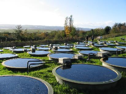
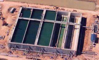
6 ii) ensile force is small: If eel is provided on both faces then the equation derived in case 1 is valid. When eel is provided only on tension face and referring to Fig.6.3, an approximate method may be used as given below b d' C D d e=m/ z=jd Fig. 6.3 d' s Equilibrium of forces give s -C= aking moment about centroid of tensile reinforcement Cjd= (e-d/+d ) Let E= e-d/+d = e-d/+(d-d)=e+d/-d E C Subituting in equilibrium equation jd E A jd E A jd 6.6 WAER ANKS : A water tank is used to ore water to facilitate the daily requirements of habitats. ypes of water tank based on placing and shape is given in Fig Circular tanks have minimum surface area when compared to other shapes for a particular capacity of orage required. Hence the quantity of material required for circular water tank is less than required for other shapes. But the form work for a circular tank is very complex and expensive when compared to other shapes. Square and Rectangular water tanks are generally used under ground or on the ground. Circular tanks are preferred for elevated tanks. 6


7 Fig. 6.4 WAER ANK BASED ON PLACEMEN OF ANK BASED ON SHAPE OF ANK 1. RESING ON GROUND. UNDER GROUND 3. ELEVAED 1. CIRCULAR. RECANGULAR 3. SPHERICAL 4. INZ 5. CONICAL BOOM Reing on ground Under Ground 7

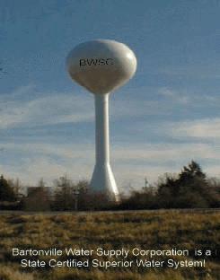

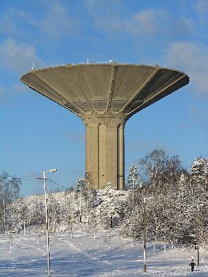
8 Elevated Circular Rectangular Spherical Intz Conical Bottom 8
9 6.6.1 Circular anks reing on ground : Due to hydroatic pressure, the tank has tendency to increase in diameter. his increase in diameter all along the height of the tank depends on the nature of joint at the junction of slab and wall as shown in Fig 6.5 ank with flexible base ank with rigid base Fig
10 When the joints at base are flexible, hydroatic pressure induces maximum increase in diameter at base and no increase in diameter at top. his is due to fact that hydroatic pressure varies linearly from zero at top and maximum at base. Deflected shape of the tank is shown in Fig When the joint at base is rigid, the base does not move. he vertical wall deflects as shown in Fig Design of Circular anks reing on ground with flexible base: Maximum hoop tension in the wall is developed at the base. his tensile force is computed by considering the tank as thin cylinder D H ; Quantity of reinforcement required in form of hoop eel is computed HD / as A or 0.3 % (minimum) When the thickness of the wall is less than 5 mm, the eel placed at centre. When the thickness exceeds 5mm, at each face A / of eel as hoop reinforcement is provided In order to provide tensile ress in concrete to be less to be less than permissible ress, the ress in concrete is computed using equation HD / c If c cat, where cat =0.7f ck, then the A (m 1)A 1000t (m 1)A c section is from cracking, otherwise the thickness has to be increased so that c is less than cat. While designing, the thickness of concrete wall can be eimated as t=30h+50 mm, where H is in meters. Diribution eel in the form of vertical bars are provided such that minimum eel area requirement is satisfied. As base slab is reing on ground and no bending resses are induced hence minimum eel diributed at bottom and the top are provided Design Problem: Design a circular water tank with flexible connection at base for a capacity of 4,00,000 liters. he tank res on a firm level ground. he height of tank including a free board of 00 mm should not exceed 3.5m. he tank is open at top. Use M 0 concrete and Fe 415 eel. Draw to a suitable scale: i) Plan at base ii) Cross section through centre of tank. Solution: Step 1: Dimension of tank Depth of water H= = 3.3 m Volume V = 4,00,000/1000 = 400 m 3 Area of tank A = 400/3.3 = 11. m Diameter of tank D 4A 1.4m 13 m 10
11 he thickness is assumed as t = 30H+50= mm Step : Design of Vertical wall D Max hoop tension at bottom H 14.5kN Area of eel A 1430 mm 150 Minimum eel to be provided A min =0.4%of area of concrete = 0.4x 1000x160/100 = 384 mm he eel required is more than the minimum required Let the diameter of the bar to be used be 16 mm, area of each bar =01 mm Spacing of 16 mm diameter bar=1430x 1000/01= mm c/c Provide 140 c/c as hoop tension eel Step 3: Check for tensile ress Area of eel provided A provided =01x1000/140 = mm Modular ratio m= Stress in concrete c 1. N/mm 1000t (m 1)A ( )1436 Permissible ress cat =0.7f ck = 1. N/mm Actual ress is equal to permissible ress, hence safe. Step 4: Curtailment of hoop eel: Quantity of eel required at 1m, m, and at top are tabulated. In this table the maximum spacing is taken an 3 x 160 = 480 mm Height from top Hoop tension =HD/ (kn) A = / Spacing of #16 mm c/c.3 m m op 0 Min eel (384 mm ) 400 Step 5: Vertical reinforcement: For temperature and shrinkage diribution eel in the form of vertical reinforcement is 0.4 % ie., A =384 mm. Spacing of 10 mm diameter bar = 78.54x1000/384=04 mm c/c 00 mm c/c Step 6: ank floor: As the slab res on firm ground, minimum 0.3 % is provided. hickness of slab is assumed as 150 mm. 8 mm diameter bars at 00 c/c is provided in both directions at bottom and top of the slab. 11
12 1
13 Design of Circular anks reing on ground with rigid base: Due to fixity at base of wall, the upper part of the wall will have hoop tension and lower part bend like cantilever. For shallow tanks with large diameter, hoop resses are very small and the wall act more like cantilever. For deep tanks of small diameter the cantilever action due to fixity at the base is small and the hoop action is predominant. he exact analysis of the tank to determine the portion of wall in which hoop tension is predominant and the other portion in which cantilever action is predominant, is difficult. Simplified methods of analysis are i) Reissner s method ii) Carpenter s simplified method iii) Approximate method iv) IS code method Use of IS code method for analysis and design of circular water tank with rigid base is udied in this course. IS code method ables 9,10 and 11 of IS 3370 part IV gives coefficients for computing hoop tension, moment and shear for various values of H /Dt Hoop tension, moment and shear is computed as = coefficient ( w HD/) M= coefficient ( w H 3 ) V= coefficient ( w H ) hickness of wall required is computed from BM consideration ie., M d Qb where, Q= ½ jk m k m j=1-(k/3) b = 1000mm Providing suitable cover, the over all thickness is then computed as t = d+cover. Area of reinforcement in the form of vertical bars on water face is computed as M A. Area of hoop eel in the form of rings is computed as A 1 jd Diribution eel and vertical eel for outer face of wall is computed from minimum eel consideration. ensile ress computed from the following equation should be less than the permissible ress for safe design c and the permissible ress is 0.7 f ck 1000t (m 1)A Base slab thickness generally varies from 150mm to 50 mm and minimum eel is diributed to top and bottom of slab. 13
14 Design Problem No.1: A cylindrical tank of capacity 7,00,000 liters is reing on good unyielding ground. he depth of tank is limited to 5m. A free board of 300 mm may be provided. he wall and the base slab are ca integrally. Design the tank using M0 concrete and Fe415 grade eel. Draw the following i) Plan at base ii) Cross section through centre of tank. Solution: Step 1: Dimension of tank H= = 4.7 and volume V = 700 m 3 A=700/4.7 = m D= (4 x /) = m Step : Analysis for hoop tension and bending moment One meter width of the wall is considered and the thickness of the wall is eimated as t=30h+50 = 191 mm. he thickness of wall is assumed as 00 mm. H Dt Referring to table 9 of IS3370 (part IV), the maximu m coefficient for hoop tension = max =0.575 x 10 x 4.7 x 7 = kn Referring to table 10 of IS3370 (part IV), the maximum coefficient for bending moment = (produces tension on water side) M max = x 10 x =15.15 kn-m Step 3: Design of section: For M0 concrete =7, For Fe415 eel =150 MPa and m=13.33 for M0 concrete and Fe415 eel he design conants are: m k 0.39 m j=1-(k/3)=0.87 Q= ½ jk = 1.19 Effective depth is calculated as Step 3: Design of section: For M0 concrete =7, For Fe415 eel =150 MPa and m=13.33 for M0 concrete and Fe415 eel he design conants are: m k 0.39 m j=1-(k/3)=0.87 Q= ½ jk = 1.19 Effective depth is calculated as d M Qb x mm 1.19x
15 Let over all thickness be 00 mm with effective cover 33 mm d provided =167 mm 6 M 15.15x10 A mm jd 150x0.87x167 01x1000 Spacing of 16 mm diameter bar = 89.3mmc / c Provide #16@75 c/c as vertical reinforcement on water face x10 Hoop eel: A 1 161mm x1000 Spacing of 1 mm diameter bar = 89.mmc / c 161 Provide #1@80 c/c as hoop reinforcement on water face 113x1000 Actual area of eel provided A 141.5mm 80 (Max spacing 3d=501mm) Step 4: Check for tensile ress: x10 c 0.87N / mm 1000t (m 1)A 1000x00 ( )x141.5 Permissible ress = 0.7f ck =1. N/mm > c Safe Step 5: Diribution Steel: Minimum area of eel is 0.4% of concrete area A =(0.4/100) x1000 x 00 = 480 mm Spacing of 8 mm diameter bar = 50.4x mmc / c Provide 100 c/c as vertical and horizontal diribution on the outer face. Step 5: Base slab: he thickness of base slab shall be 150 mm. he base slab res on firm ground, hence only minimum reinforcement is provided. A =(0.4/100) x1000 x 150 = 360 mm Reinforcement for each face = 180 mm 50.4x1000 Spacing of 8 mm diameter bar = 79.mmc / c 180 Provide 50 c/c as vertical and horizontal diribution on the outer face. 15
16 16
17 Design Problem No.: Design a circular water tank to hold 5,50,000 liters of water. Assume rigid joints between the wall and base slab. Adopt M0 concrete and Fe 415 eel. Sketch details of reinforcements. Solution: Step 1: Dimension of tank Volume of tank V=550 m 3 Assume H= 4.5 A=550/4.5 = 1. m D= (4 x 1./) = m Step : Analysis for hoop tension and bending moment One meter width of the wall is considered and the thickness of the wall is eimated as t=30h+50 = 185 mm. he thickness of wall is assumed as 00 mm. H Dt Referring to table 9 of IS3370 (part IV), the maximum coefficient for hoop tension = max =0.575 x 10 x 4.5 x 6.5 =161.7 kn Referring to table 10 of IS3370 (part IV), the maximum coefficient for bending moment = (produces tension on water side) M max = x 10 x =13.3 kn-m Step 3: Design of section: For M0 concrete =7, For Fe415 eel =150 MPa and m=13.33 for M0 concrete and Fe415 eel he design conants are: m k 0.39 m j=1-(k/3)=0.87 Q= ½ jk = M 13.3x10 Effective depth is calculated as d 105.7mm Qb 1.19x1000 Let over all thickness be 00 mm with effective cover 33 mm d provided =167 mm 6 M 13.3x10 A 610.7mm jd 150x0.87x167 01x1000 Spacing of 16 mm diameter bar = 39.36mmc / c Provide #16@300 c/c as vertical reinforcement on water face x10 Hoop eel: A mm 150 (Max spacing 3d=501mm) 17
18 113x1000 Spacing of 1 mm diameter bar = 104mmc / c Provide #1@100 c/c as hoop reinforcement on water face 113x1000 Actual area of eel provided A 1130mm 100 Step 4: Check for tensile ress: x10 c 1000t (m 1)A 1000x00 ( )x1130 Permissible ress = 0.7f ck =1. N/mm > c Safe 0.76N / mm Step 5: Diribution Steel: Minimum area of eel is 0.4% of concrete area A =(0.4/100) x1000 x 00 = 480 mm Spacing of 8 mm diameter bar = 50.4x mmc / c Provide 100 c/c as vertical and horizontal diribution on the outer face. Step 5: Base slab: he thickness of base slab shall be 150 mm. he base slab res on firm ground, hence only minimum reinforcement is provided. A =(0.4/100) x1000 x 150 = 360 mm Reinforcement for each face = 180 mm 50.4x1000 Spacing of 8 mm diameter bar = 79.mmc / c 180 Provide 50 c/c as vertical and horizontal diribution on the outer face. 18
19 19
20 6.6. Rectangular tank with fixed base reing on ground : Rectangular tanks are used when the orage capacity is small and circular tanks prove uneconomical for small capacity. Rectangular tanks should be preferably square in plan from point of view of economy. It is also desirable that longer side should not be greater than twice the smaller side. Moments are caused in two directions of the wall ie., both in horizontal as well as in vertical direction. Exact analysis is difficult and such tanks are designed by approximate methods. When the length of the wall is more in comparison to its height, the moments will be mainly in the vertical direction, ie., the panel bends as vertical cantilever. When the height is large in comparison to its length, the moments will be in the horizontal direction and panel bends as a thin slab supported on edges. For intermediate condition bending takes place both in horizontal and vertical direction. In addition to the moments, the walls are also subjected to direct pull exerted by water pressure on some portion of walls. he walls are designed both for direct tension and bending moment. ` B C p=h B A D L BASE FBD OF AB IN PLAN FBD OF AD IN PLAN + 0.5b 0.5b y - a Bending moment diagram x IS3370 (Part -IV) gives tables for moments and shear forces in walls for certain edge condition. able 3 of IS3370 provides coefficient for max Bending moments in horizontal and vertical direction. Maximum vertical moment = M x w a 3 ( for x/a = 1, y=0) Maximum horizontal moment = M y w a 3 (for x/a = 0, y=b/) 0
21 ension in short wall is computed as s =pl/ ension in long wall L =pb/ Horizontal eel is provided for net bending moment and direct tensile force M' A =A 1 +A ; A 1 ; M =Maximum horizontal bending moment x; x= d-d/ jd A =/ d D/ x Design problem No.1 Design a rectangular water tank 5m x 4m with depth of orage 3m, reing on ground and whose walls are rigidly joined at vertical and horizontal edges. Assume M0 concrete and Fe415 grade eel. Sketch the details of reinforcement in the tank Solution: Step1: Analysis for moment and tensile force E C A Free a=h=3m Fixed D L=5m B F b=4m i) Long wall: L/a= ; at y=0, x/a=1, M x =-0.074; at y=b/, x/a=1/4, M y =-0.05 Max vertical moment = M x w a 3 = Max horizontal moment = M y w a 3 = ; long = w ab/=60 kn ii) Short wall: B/a= ; at y=0, x/a=1, M x =-0.06; at y=b/, x/a=1/4, M y = Max vertical moment = M x w a 3 = -16. Max horizontal moment = M y w a 3 = ; short = w al/=75 kn 1
22 Step: Design conants =7 MPa, =150 MPa, m=13.33 m k 0.38 m j=1-(k/3)=0.87 Q= ½ jk = 1.15 Step3: Design for vertical moment For vertical moment, the maximum bending moment from long and short wall (M max ) x = kn-m d M Qb x mm 1.15x1000 Assuming effective cover as 33mm, the thickness of wall is t= =164.8 mm170 mm d provided =170-33=137mm 6 M 19.98x10 A mm jd 150x0.87x137 Spacing of 1 mm diameter bar = 113x Provide 100 mm c/c Diribution eel Minimum area of eel is 0.4% of concrete area A =(0.4/100) x1000 x 170 = 408 mm Spacing of 8 mm diameter bar = 50.4x mmc / c (Max spacing 3d=411mm) 13.19mmc / c Provide 10 c/c as diribution eel. Provide 10 c/c as vertical and horizontal diribution on the outer face. Step4: Design for Horizontal moment Horizontal moments at the corner in long and short wall produce unbalanced moment at the joint. his unbalanced moment has to be diributed to get balanced moment using moment diribution method. A B 14.4 C K AC DF DF AC AB 1 1 ; K AC ; 5 5 1/ / 0 1/ / 0 K 9 0
23 Moment diribution able Joint A Member AC AB DF FEM Diribution Final Moment he tension in the wall is computed by considering the section at height H 1 from the base. Where, H 1 is greater of i) H/4, ii) 1m, ie., i) 3/4=0.75, ii) 1m; H 1 = 1m Depth of water h=h-h 1 =3-1-m; p= w h=10 x = 0 kn/m ension in short wall s =pl/=50 kn ension in long wall L =pb/= 40 kn Net bending moment M =M-x, where, x= d-d/=137-(170/)=5mm M = x 0.05= kn-m x10 A mm 150x0.87x x10 A mm 150 A =A 1 +A = mm 113x1000 Spacing of 1 mm diameter bar = 13 mmc / c (Max spacing 3d=411mm) Provide #1@10 mm c/c at corners Step5: Base Slab: he slab is reing on firm ground. Hence nominal thickness and reinforcement is provided. he thickness of slab is assumed to be 00 mm and 0.4% reinforcement is provided in the form of 00 c/c. at top and bottom A haunch of 150 x 150 x 150 mm size is provided at all corners 3
24 4
Flexure and Serviceability Limit State
 UNIT 3 Flexure and Serviceability Limit State Beam A structural member that support transverse (Perpendicular to the axis of the member) load is called a beam. Beams are subjected to bending moment and
Code No: R Set No. 1
 Code No: R059210303 Set No. 1 II B.Tech I Semester Regular Examinations, November 2006 MECHANICS OF SOLIDS ( Common to Mechanical Engineering, Mechatronics, Metallurgy & Material Technology, Production
2016 DESIGN AND DRAWING OF REINFORCED CONCRETE STRUCTURES
 R13 SET - 1 DESIGN AND DRAWING OF REINFCED CONCRETE STRUCTURES 1 Design a simply supported rectangular beam to carry 30kN/m superimposed load over a span of 6m on 460mm wide supports. Use M20 grade concrete
CHAPTER 2. Design Formulae for Bending
 CHAPTER 2 Design Formulae for Bending Learning Objectives Appreciate the stress-strain properties of concrete and steel for R.C. design Appreciate the derivation of the design formulae for bending Apply
6. Design of Portal Frames (For class held on 20 th, 26 th and 27 th March 07)
") 6. Design of Portal Frames (For class held on 0 th, 6 th and 7 th March 07) By Dr. G.S.Suresh, Professor, Civil Engineering Department, NIE, Mysore (Ph:934188467, email: gss_nie@ yahoo.com) 3.1 Introduction:
6. Design of Portal Frames (For class held on 0 th, 6 th and 7 th March 07) By Dr. G.S.Suresh, Professor, Civil Engineering Department, NIE, Mysore (Ph:934188467, email: gss_nie@ yahoo.com) 3.1 Introduction:
COLUMNS. Classification of columns:
 COLUMNS are vertical compression members in structures, the effective length of which exceeds three times its lateral dimension. Which are provided for bear the load of Beam, Slab, etc. since columns support
GATE SOLVED PAPER - CE
 YEAR 2013 Q. 1 Maximum possible value of compaction factor for fresh (green) concrete is (A) 0.5 (B) 1.0 (C) 1.5 (D) 2.0 Q. 2 As per IS 456 : 2000, bond strength of concrete t bd = 12. for M20. It is increased
BEAMS: COMPOSITE BEAMS; STRESS CONCENTRATIONS
 BEAMS: COMPOSITE BEAMS; STRESS CONCENTRATIONS Slide No. 1 Bending of In the previous discussion, we have considered only those beams that are fabricated from a single material such as steel. However, in
Diploma in Civil Engineering. Term-End Examination June, BCE-041 : THEORY OF STRUCTURES II
 No. of Printed Pages : 6 BCE-041 Diploma in Civil Engineering Term-End Examination June, 2012 00819 BCE-041 : THEORY OF STRUCTURES II Time : 2 hours Maximum Marks : 70 Note : Question number 1 is compulsory.
VTU EDUSAT PROGRAMME Lecture Notes on Design of Stair cases
 VTU EDUSAT PROGRAMME 17 2012 Lecture Notes on Design of Stair cases DESIGN OF RCC STRUCTURAL ELEMENTS - 10CV52 (PART B, UNIT 8) Dr. M. C. Nataraja Professor, Civil Engineering Department, Sri Jayachamarajendra
CIVIL ENGINEERING YEAR QUESTION BANK
 CE 6505-DESIGN OF RC ELEMENTS CIVIL ENGINEERING SEM- V YEAR 2015-16 STAFF NAME: THIVAKAR.S A/P QUESTION BANK Subject Name: DESIGN OF RC ELEMENTS Subject Code: CE6505 PART-A UNIT I 1. What are the advantages
UNIT-I DESIGN CONCEPTS, DESIGN OF BEAMS Part - A (Short Answer Questions)
") S.NO IMPORTANT QUESTIONS UNIT-I DESIGN CONCEPTS, DESIGN OF BEAMS Part - A (Short Answer Questions) 1 What are the three methods of design of reinforced concrete structural elements? 2 State four objectives
S.NO IMPORTANT QUESTIONS UNIT-I DESIGN CONCEPTS, DESIGN OF BEAMS Part - A (Short Answer Questions) 1 What are the three methods of design of reinforced concrete structural elements? 2 State four objectives
COMPARATIVE STUDY OF DESIGN OF WATER TANK WITH NEW PROVISIONS
 e-sn 2455 1392 Volume 2 Issue 4, April 2016 pp. 481-485 Scientific Journal Impact Factor : 3.468 http://www.ijcter.com COMPARATIVE STUDY OF DESIGN OF WATER TANK WITH NEW PROVIONS Sneha S. Shende 1, Sanjay
UNIT I SIMPLE STRESSES AND STRAINS, STRAIN ENERGY
 SIDDHARTH GROUP OF INSTITUTIONS :: PUTTUR Siddharth Nagar, Narayanavanam Road 517583 QUESTION BANK (DESCRIPTIVE) Subject with Code: Year & Sem: II-B.Tech & I-Sem Course & Branch: B.Tech - ME Regulation:
Lecture Retaining Wall Week 12
 Lecture Retaining Wall Week 12 Retaining walls which provide lateral support to earth fill embankment or any other form of material which they retain them in vertical position. These walls are also usually
1.Axial Force, Shear Force and Bending Moment:
 1 TRIBHUVAN UNIVERSITY INSTITUTE OF ENGINEERING PULCHOWK CAMPUS (Pulchowk, Lalitpur) Subject: Strength of Materials(II/I) (Tutorial ) 1.Axial Force, Shear Force and Bending Moment: 1. Draw AFD, SFD and
SIDDHARTH GROUP OF INSTITUTIONS :: PUTTUR Siddharth Nagar, Narayanavanam Road QUESTION BANK (DESCRIPTIVE)
") SIDDHARTH GROUP OF INSTITUTIONS :: PUTTUR Siddharth Nagar, Narayanavanam Road 517583 QUESTION BANK (DESCRIPTIVE) Subject with Code : DDRCS(13A01502) Year & Sem: III-B.Tech & I-Sem Course & Branch: B.Tech
SIDDHARTH GROUP OF INSTITUTIONS :: PUTTUR Siddharth Nagar, Narayanavanam Road 517583 QUESTION BANK (DESCRIPTIVE) Subject with Code : DDRCS(13A01502) Year & Sem: III-B.Tech & I-Sem Course & Branch: B.Tech
1 Prepared By:Mr.A.Sathiyamoorthy, M.E., AP/Civil
 UNIVERSITY QUESTIONS PART A UNIT 1: INTRODUCTION THEORY AND BEHAVIOUR 1. List the loss of prestress. 2. Define axial prestressing. 3. What is the need for the use of high strength concrete and tensile
UNIVERSITY OF BOLTON WESTERN INTERNATIONAL CENTRE FZE. BEng (HONS) CIVIL ENGINEERING SEMESTER ONE EXAMINATION 2015/2016
 CIVIL ENGINEERING SEMESTER ONE EXAMINATION 2015/2016") OCD59 UNIVERSITY OF BOLTON WESTERN INTERNATIONAL CENTRE FZE BEng (HONS) CIVIL ENGINEERING SEMESTER ONE EXAMINATION 2015/2016 ADVANCED STRUCTURAL ANALYSIS AND DESIGN MODULE NO: CIE6001 Date: Tuesday 12
OCD59 UNIVERSITY OF BOLTON WESTERN INTERNATIONAL CENTRE FZE BEng (HONS) CIVIL ENGINEERING SEMESTER ONE EXAMINATION 2015/2016 ADVANCED STRUCTURAL ANALYSIS AND DESIGN MODULE NO: CIE6001 Date: Tuesday 12
Flat Slabs. d 2. A typical flat slab (without drop and column head)
") 1 CHAPTER Flat Slabs 1.1 INTRDUCTIN Common practice of design and construction is to support the slabs by beams and support the beams by columns. This may be called as beam-slab construction. The beams
1 CHAPTER Flat Slabs 1.1 INTRDUCTIN Common practice of design and construction is to support the slabs by beams and support the beams by columns. This may be called as beam-slab construction. The beams
Subject with Code: Strength of Materials(16CE104) Course& Branch: B. Tech - CE Year &Sem : II-B. Tech &I-Sem Regulation: R16
 Course& Branch: B. Tech - CE Year &Sem : II-B. Tech &I-Sem Regulation: R16") SIDDHARTH INSTITUTE OF ENGINEERING &TECHNOLOGY:: PUTTUR (Approved by AICTE, New Delhi & Affiliated to JNTUA, Anantapuramu) (Accredited by NBA & Accredited by NAAC with A Grade) (An ISO 9001:2008 Certified
SIDDHARTH INSTITUTE OF ENGINEERING &TECHNOLOGY:: PUTTUR (Approved by AICTE, New Delhi & Affiliated to JNTUA, Anantapuramu) (Accredited by NBA & Accredited by NAAC with A Grade) (An ISO 9001:2008 Certified
FE Review Mechanics of Materials
 1 2 3 4 5 6 7 8 9 10 11 12 13 14 15 16 17 18 19 20 21 22 23 24 25 26 27 28 29 1. T he element is subjected to the plane stress condition shown. a-x = - 140 M Pa a- y = 205 M Pa Txy = 100 M Pa What is t
REINFORCED CONCRETE DESIGN 1. Analysis of Section (Examples and Tutorials)
") Analysis of Section (Example and Tutorials) by Sharifah Maszura Syed Mohsin For updated version, please click on http://ocw.ump.edu.my REINFORCED CONCRETE DESIGN 1 Analysis of Section (Examples and Tutorials)
Analysis of Section (Example and Tutorials) by Sharifah Maszura Syed Mohsin For updated version, please click on http://ocw.ump.edu.my REINFORCED CONCRETE DESIGN 1 Analysis of Section (Examples and Tutorials)
ST7008 PRESTRESSED CONCRETE
 ST7008 PRESTRESSED CONCRETE QUESTION BANK UNIT-I PRINCIPLES OF PRESTRESSING PART-A 1. Define modular ratio. 2. What is meant by creep coefficient? 3. Is the deflection control essential? Discuss. 4. Give
SIDDHARTH GROUP OF INSTITUTIONS :: PUTTUR Siddharth Nagar, Narayanavanam Road QUESTION BANK (DESCRIPTIVE)
") SIDDHARTH GROUP OF INSTITUTIONS :: PUTTUR Siddharth Nagar, Narayanavanam Road 517583 QUESTION BANK (DESCRIPTIVE) Subject with Code :Strength of Materials-II (16CE111) Course & Branch: B.Tech - CE Year
SIDDHARTH GROUP OF INSTITUTIONS :: PUTTUR Siddharth Nagar, Narayanavanam Road 517583 QUESTION BANK (DESCRIPTIVE) Subject with Code :Strength of Materials-II (16CE111) Course & Branch: B.Tech - CE Year
DESIGN OF SLABS. 3) Based on support or boundary condition: Simply supported, Cantilever slab,
 Based on support or boundary condition: Simply supported, Cantilever slab,") DESIGN OF SLABS Dr. G. P. Chandradhara Professor of Civil Engineering S. J. College of Engineering Mysore 1. GENERAL A slab is a flat two dimensional planar structural element having thickness small compared
DESIGN OF SLABS Dr. G. P. Chandradhara Professor of Civil Engineering S. J. College of Engineering Mysore 1. GENERAL A slab is a flat two dimensional planar structural element having thickness small compared
 VALLIAMMAI ENGINEERING COLLEGE DEPARTMENT OF MECHANICAL ENGINEERING QUESTION BANK CE 6306 - STRENGTH OF MATERIALS UNIT I STRESS STRAIN DEFORMATION OF SOLIDS PART- A (2 Marks) 1. What is Hooke s Law? 2.
DESIGN AND DETAILING OF RETAINING WALLS
 DESIGN AND DETAILING OF RETAINING WALLS (For class held from nd April 07) Dr. M. C. Nataraja, Professor, Civil Engineering Department, Sri Jayachamarajendra Collge of Engineering, Mysore-5a70 006 Phone:
Level 6 Graduate Diploma in Engineering Structural analysis
 9210-111 Level 6 Graduate Diploma in Engineering Structural analysis Sample Paper You should have the following for this examination one answer book non-programmable calculator pen, pencil, ruler, drawing
CE2401-DESIGN OF REINFORCED CONCRETE AND BRICK MASONRY QUESTION BANK
 CE2401-DESIGN OF REINFORCED CONCRETE AND BRICK MASONRY QUESTION BANK UNIT-1 PART-A 1. What is a Retaining wall? 2. What are the disadvantages of gravity retaining walls? 3. What are the types of retaining
Question Paper Code : 11410
 Reg. No. : Question Paper Code : 11410 B.E./B.Tech. DEGREE EXAMINATION, APRIL/MAY 2011 Fourth Semester Mechanical Engineering ME 2254 STRENGTH OF MATERIALS (Common to Automobile Engineering and Production
Design and Seismic Analysis of Ground Supported Water Tank
 Kalpa Publications in Civil Engineering Volume 1, 2017, Pages 1 6 ICRISET2017. International Conference on Research and Innovations in Science, Engineering &Technology. Selected papers in Civil Engineering
THE ECONOMIC ANALYSIS & DESIGN OF R.C.C. & PRESTRESSED CONCRETE WATER TANK RESTING ON THE GROUND
 International Research Journal of Engineering and Technology (IRJET) e-issn: 2395-0056 THE ECONOMIC ANALYSIS & DESIGN OF R.C.C. & PRESTRESSED CONCRETE WATER TANK RESTING ON THE GROUND Novendra kumar verma,
UNIT-1 RETAINING WALLS
 UNIT-1 RETAINING WALLS PART-A 1. Describe about Retaining wall. 2. Define gravity retaining walls. BT-1 3. Classify the types of retaining walls. 4. Explain cantilever retaining wall? 5. Describe about
DESIGN OF RC ELEMENTS UNIT 1 PART-A
 DESIGN OF RC ELEMENTS UNIT 1 PART-A 1. Calculate the design strength for M 30 grade concrete and Fe 415 grade steel? 2. What is the important principle of ultimate load method? 3. Write the classification
COST ANALYSIS OF DOME STRUCTURE WITH RING BEAM
 COST ANALYSIS OF DOME STRUCTURE WITH RING BEAM B. H. V. Pai 1 and B. Durga Prasad Baliga 2 1 Department of Civil Engineering, Manipal Institute of Technology, Manipal, Udupi, Karnataka, India 2 Department
IV. IS GUIDELINES & PROBLEM DEFINITION
 Design and Optimization of RCC Silo Afzal Ansari 1, Kashif Armaghan 2, Sachin S. Kulkarni 3 1,2 B.E Students, Department of Civil Engineering, Secab Institute of Engineering & Technology, Vijayapur 3 Assistant
COMPARISION OF DESIGN OF WATER TANK AS PER IS 3370 (1967) AND IS 3370 (2009)
 AND IS 3370 (2009)") COMPARION OF DESIGN OF WATER TANK AS PER () AND () Prof. Yogesh Kumar Bajpai 1, Saurabh Pare 2 1 Head of Department, Civil Engineering Department, Gyan Ganga institute of technology and sciences, Jabalpur,
COMPARION OF DESIGN OF WATER TANK AS PER () AND () Prof. Yogesh Kumar Bajpai 1, Saurabh Pare 2 1 Head of Department, Civil Engineering Department, Gyan Ganga institute of technology and sciences, Jabalpur,
OXFORD ENGINEERING COLLEGE (NAAC Accredited with B Grade) Department of Civil Engineering LIST OF QUESTIONS
 Department of Civil Engineering LIST OF QUESTIONS") OXFORD ENGINEERING COLLEGE (NAAC Accredited with B Grade) Department of Civil Engineering LIST OF QUESTIONS Year/ Sem. : IV / VII Staff Name : S.LUMINA JUDITH Subject Code : CE 6702 Sub. Name : PRE STRESSED
OXFORD ENGINEERING COLLEGE (NAAC Accredited with B Grade) Department of Civil Engineering LIST OF QUESTIONS Year/ Sem. : IV / VII Staff Name : S.LUMINA JUDITH Subject Code : CE 6702 Sub. Name : PRE STRESSED
SIDDHARTH GROUP OF INSTITUTIONS :: PUTTUR Siddharth Nagar, Narayanavanam Road QUESTION BANK (DESCRIPTIVE) UNIT-5 FOOTINGS & STAIRS
 UNIT-5 FOOTINGS & STAIRS") SIDDHARTH GROUP OF INSTITUTIONS :: PUTTUR Siddharth Nagar, Narayanavanam Road 517583 QUESTION BANK (DESCRIPTIVE) Subject with Code : DDRCS(13A01502) Year & Sem: III-B.Tech & I-Sem Course & Branch: B.Tech
SIDDHARTH GROUP OF INSTITUTIONS :: PUTTUR Siddharth Nagar, Narayanavanam Road 517583 QUESTION BANK (DESCRIPTIVE) Subject with Code : DDRCS(13A01502) Year & Sem: III-B.Tech & I-Sem Course & Branch: B.Tech
Questions with Solution
 Questions with Solution Q 1. Vus/d depends on a) Asv b) spacing of shear reinforcement c) grade of steel d) all of these. Refer Cl. 40.4 (a), pg. 73 IS 456:2000 V us = 0.87 f y A sv d s v 1. (d) all of
KSK COLLEGE OF ENGINEERING AND TECHNOLOGY DEPARTMENT OF CIVIL ENGINEERING CE 2505-DESIGN OF RC ELEMENTS QUESTION BANK
 KSK COLLEGE OF ENGINEERING AND TECHNOLOGY DEPARTMENT OF CIVIL ENGINEERING CE 2505-DESIGN OF RC ELEMENTS QUESTION BANK PARTA UNIT I 1. What are the advantages of limit state method over working stress and
Flexural Analysis and Design of Beams. Chapter 3
 Flexural Analysis and Design of Beams Chapter 3 Introduction Fundamental Assumptions Simple case of axial loading Same assumptions and ideal concept apply This chapter includes analysis and design for
International Journal of Advance Engineering and Research Development
 Scientific Journal of Impact Factor (SJIF): 4.72 International Journal of Advance Engineering and Research Development Volume 4, Issue 1, January -2017 e-issn (O): 2348-4470 p-issn (P): 2348-6406 PARAMETRIC
CHAPTER 12. Composite Beams Steel reinforced timber beams E, I, M,=- E, I, M,= - R
 CHAPTER 12 Composite Beams Frequently in civil engineering construction beams are fabricated from comparatively inexpensive materials of low strength which are reinforced by small amounts of high-strength
9.6 Circular Prestressing
 9.6 Circular Prestressing This section covers the following topics. Introduction General Analysis and Design Prestressed Concrete Pipes Liquid Storage Tanks Ring Beams Conclusion 9.6.1 Introduction When
PRESTRESSED CONCRETE STRUCTURES. Amlan K. Sengupta, PhD PE Department of Civil Engineering Indian Institute of Technology Madras
 PRESTRESSED CONCRETE STRUCTURES Amlan K. Sengupta, PhD PE Department of Civil Engineering Indian Institute of Technology Madras Module - 4: Design of Members Lecture - 17: Design of Members for Axial Tension
UNIVERSITY OF BOLTON WESTERN INTERNATIONAL COLLEGE FZE. BEng (HONS) CIVIL ENGINEERING SEMESTER ONE EXAMINATION 2018/2019
 CIVIL ENGINEERING SEMESTER ONE EXAMINATION 2018/2019") OCD030 UNIVERSITY OF BOLTON WESTERN INTERNATIONAL COLLEGE FZE BEng (HONS) CIVIL ENGINEERING SEMESTER ONE EXAMINATION 2018/2019 ADVANCED STRUCTURAL ANALYSIS AND DESIGN MODULE NO: CIE6001 Date: Tuesday 8
OCD030 UNIVERSITY OF BOLTON WESTERN INTERNATIONAL COLLEGE FZE BEng (HONS) CIVIL ENGINEERING SEMESTER ONE EXAMINATION 2018/2019 ADVANCED STRUCTURAL ANALYSIS AND DESIGN MODULE NO: CIE6001 Date: Tuesday 8
Sabah Shawkat Cabinet of Structural Engineering 2017
 3.1-1 Continuous beams Every building, whether it is large or small, must have a structural system capable of carrying all kinds of loads - vertical, horizontal, temperature, etc. In principle, the entire
UNIT IVCOMPOSITE CONSTRUCTION PART A
 UNIT IVCOMPOSITE CONSTRUCTION PART A 1. What is composite section of pestressed concrete? [A/M 16] A composite section in context of prestressed concrete members refers to a section with a precast member
PRESTRESSED CONCRETE STRUCTURES. Amlan K. Sengupta, PhD PE Department of Civil Engineering Indian Institute of Technology Madras
 PRESTRESSED CONCRETE STRUCTURES Amlan K. Sengupta, PhD PE Department of Civil Engineering Indian Institute of Technology Madras Module 3: Analysis of Members Lecture 13: Cracking Moment, Kern Point and
PRESTRESSED CONCRETE STRUCTURES. Amlan K. Sengupta, PhD PE Department of Civil Engineering Indian Institute of Technology Madras
 PRESTRESSED CONCRETE STRUCTURES Amlan K. Sengupta, PhD PE Department of Civil Engineering Indian Institute of Technology Madras Module 7: Transmission of Prestress Lecture 30: Pre-tensioned Members Welcome
7.1 Transmission of Prestress (Part I)
") 7.1 Transmission of Prestress (Part I) This section covers the following topics. Pre-tensioned Members 7.1.1 Pre-tensioned Members The stretched tendons transfer the prestress to the concrete leading to
7.1 Transmission of Prestress (Part I) This section covers the following topics. Pre-tensioned Members 7.1.1 Pre-tensioned Members The stretched tendons transfer the prestress to the concrete leading to
COLUMNS 1- Definition: The Egyptian code defines columns as : 2- Types of concrete columns
 COLUMNS 1- Definition: Columns are vertical compression members which carry primarily axial compression load; the axial load may be associated with bending moments in one or two directions, as shown in
PRESTRESSED CONCRETE STRUCTURES. Amlan K. Sengupta, PhD PE Department of Civil Engineering Indian Institute of Technology Madras
 PRESTRESSED CONCRETE STRUCTURES Amlan K. Sengupta, PhD PE Department of Civil Engineering Indian Institute of Technology Madras Module 5: Analysis and Design for Shear and Torsion Lecture-24: Design for
VARIOUS TYPES OF SLABS
 VARIOUS TYPES OF SLABS 1 CHOICE OF TYPE OF SLAB FLOOR The choice of type of slab for a particular floor depends on many factors. Economy of construction is obviously an important consideration, but this
mortarless masonry Design Manual Part 1 (IS 456:2000) Section 1 Page 1 IS 456:2000 PLAIN AND REINFORCED CONCRETE - CODE OF PRACTICE
 Section 1 Page 1 IS 456:2000 PLAIN AND REINFORCED CONCRETE - CODE OF PRACTICE") SECTION 1. mortarless masonry Design Manual Part 1 (IS 456:2000) Section 1 Page 1 1.1 Overview of IS 456:2000 IS 456:2000 PLAIN AND REINFORCED CONCRETE - CODE OF PRACTICE IS 456:2000 is the current Indian
SECTION 1. mortarless masonry Design Manual Part 1 (IS 456:2000) Section 1 Page 1 1.1 Overview of IS 456:2000 IS 456:2000 PLAIN AND REINFORCED CONCRETE - CODE OF PRACTICE IS 456:2000 is the current Indian
Concrete Cracking. ε ctr = f ctr / E c = 0.6 / 4400 = x 10-3
 Concrete Cracking Concrete is known as a sensitive material for cracking. The code defines concrete modulus of elasticity (E c ) and concrete cracking-limit tensile stress (f ctr ) as: E c = 4400 (f cu
Comparative Analysis of Circular and Rectangular Reinforced Concrete Tanks Based on Economical Design Perspective
 American Journal of Applied Scientific Research 2017; 3(2): 14-20 http://wwwsciencepublishinggroupcom/j/ajasr doi: 1011648/jajasr2017030212 ISSN: 2471-9722 (Print); ISSN: 2471-9730 (Online) Comparative
SHEAR BEHAVIOR OF RC DEEP BEAMS WITH SOLID CIRCULAR CROSS SECTION UNDER SIMPLY SUPPORTED CONDITION AND ANTI-SYMMETRIC MOMENT
 SHEAR BEHAVIOR OF RC DEEP BEAMS WITH SOLID CIRCULAR CROSS SECTION UNDER SIMPLY SUPPORTED CONDITION AND ANTI-SYMMETRIC MOMENT Koji MATSUMOTO (Tokyo Institute of Technology) Moe YONEHANA (Kajima Corporation)
Unit II Shear and Bending in Beams
 Beams and Bending Unit II Shear and Bending in Beams 2 Marks questions and answers 1. Mention the different types of supports. i. Roller support ii. Hinged support iii. Fixed support 2. Differentiate between
Structural Characteristics of New Composite Girder Bridge Using Rolled Steel H-Section
 Proc. Schl. Eng. Tokai Tokai Univ., Univ., Ser. ESer. E 41 (2016) (2016) - 31-37 Structural Characteristics of New Composite Girder Bridge Using Rolled Steel H-Section by Mohammad Hamid ELMY *1 and Shunichi
3. Bond, Anchorage and Shear This chapter will discuss the following topics:
 3. Bond, Anchorage and Shear This chapter will discuss the following topics: Outline the theory of calculating the anchorage bond length. Determination of anchorage bond length, tension lap length and
Hours / 100 Marks Seat No.
 17422 21314 4 Hours / 100 Seat No. Instructions (1) All Questions are Compulsory. (2) Answer each next main Question on a new page. (3) Illustrate your answers with neat sketches wherever necessary. (4)
DURABILITY AND SERVICEABILITY
 DURABILITY AND SERVICEABILITY Introduction of Durability Durability requirements are to ensure that a structure has satisfactory durability and serviceability performance under normal circumstances throughout
EN REINFORCED MASONRY DESIGN EXAMPLE 1 (NOTE: THIS USES THE UK NATIONAL ANNEX NDP VALUES)
") 42.50 10.00 3.00 20.00 EN 1996-1-1 REINFORCED MASONRY DESIGN EXAMPLE 1 (NOTE: THIS USES THE UK NATIONAL ANNEX NDP VALUES) Reinforced Masonry - Reinforced Brickwork Stem Cantilever Pocket-Type Retaining
42.50 10.00 3.00 20.00 EN 1996-1-1 REINFORCED MASONRY DESIGN EXAMPLE 1 (NOTE: THIS USES THE UK NATIONAL ANNEX NDP VALUES) Reinforced Masonry - Reinforced Brickwork Stem Cantilever Pocket-Type Retaining
Questions with solution
 Questions with solution Q 1: The rectangular beam of width, 250 mm is having effective depth of 317 mm. The concrete grade is M20 and the grade of reinforcing steel is Fe415. The moment capacity of the
Long-term Stress of Simply Supported Steel-concrete Composite Beams
 The Open Construction and Building Technology Journal, 2011, 5, 1-7 1 Open Access Long-term Stress of Simply Supported Steel-concrete Composite Beams Min Ding 1,2, Xiugen Jiang 1, Zichen Lin 3 and Jinsan
A Guide for the Interpretation of Structural Design Options for Residential Concrete Structures
 CFA Technical Note: 008-2010 A Guide for the Interpretation of Structural Design Options for Residential Concrete Structures CFA Technical This CFA Technical Note is intended to serve as a guide to assist
Two-way slabs. Flat plate with or without drop panels / capitals
 Two-way slabs Two-way slab behavior is described by plate bending theory which is a complex extension of beam bending. Codes of practice allow use of simplified methods for analysis and design of two-way
UNIVERSITY OF BOLTON SCHOOL OF ENGINEERING. BEng (Hons) CIVIL ENGINEERING
 CIVIL ENGINEERING") TW7 UNIVERSITY OF BOLTON SCHOOL OF ENGINEERING BEng (Hons) CIVIL ENGINEERING SEMESTER 2 EXAMINATION 2015/2016 ADVANCED STRUCTURAL ANALYSIS & DESIGN MODULE NO. CIE6001 Date: Thursday 19 th May 2016 Time:
TW7 UNIVERSITY OF BOLTON SCHOOL OF ENGINEERING BEng (Hons) CIVIL ENGINEERING SEMESTER 2 EXAMINATION 2015/2016 ADVANCED STRUCTURAL ANALYSIS & DESIGN MODULE NO. CIE6001 Date: Thursday 19 th May 2016 Time:
Types of Foundations
 Shallow Foundations Types of Foundations Foundations can be classified to two major categories: Shallow. Deep. 1 Introduction If the soil stratum is suitable for supporting the structural loads from the
Council on Tall Buildings
 Structure Design of Sino Steel (Tianjin) International Plaza Xueyi Fu, Group Chief Engineer, China Construction Design International 1 1 Brief of Project 2 Location: Tianjin Xiangluowan Business District
R13. II B. Tech I Semester Regular/Supplementary Examinations, Dec MECHANICS OF SOLIDS (Com. to ME, AME, AE, MTE) Time: 3 hours PART-A
 Time: 3 hours PART-A") SET - 1 II B. Tech I Semester Regular/Supplementary Examinations, Dec - 2015 MECHANICS OF SOLIDS (Com. to ME, AME, AE, MTE) Time: 3 hours Max. Marks: 70 Note: 1. Question Paper consists of two parts (Part-A
SET - 1 II B. Tech I Semester Regular/Supplementary Examinations, Dec - 2015 MECHANICS OF SOLIDS (Com. to ME, AME, AE, MTE) Time: 3 hours Max. Marks: 70 Note: 1. Question Paper consists of two parts (Part-A
Dr. NAGY GYÖRGY Tamás Professor
 Dr. NAGY GYÖRGY Tamás Professor E mail: tamas.nagy gyorgy@upt.ro Tel: +40 256 403 935 Web: http://www.ct.upt.ro/users/tamasnagygyorgy/index.htm Office: A219 Dr.ing. Nagy György T. Faculty of Civil Engineering
ACI Code Revisions Impact on StructurePoint Software
 ACI 318-19 Code Revisions Impact on StructurePoint Software General Themes & Summary ACI 318-19 continues to unify and simplify code provisions started in 2014 reorganization of chapters by members. Nearly
5.4 Analysis for Torsion
 5.4 Analysis for Torsion This section covers the following topics. Stresses in an Uncracked Beam Crack Pattern Under Pure Torsion Components of Resistance for Pure Torsion Modes of Failure Effect of Prestressing
Continuous Beam Design with Moment Redistribution (CSA A )
") Continuous Beam Design with Moment Redistribution (CSA A23.3-14) Continuous Beam Design with Moment Redistribution (CSA A23.3-14) A structural reinforced concrete continuous beam at an intermediate floor
Continuous Beam Design with Moment Redistribution (CSA A23.3-14) Continuous Beam Design with Moment Redistribution (CSA A23.3-14) A structural reinforced concrete continuous beam at an intermediate floor
15.2 Approximate Analysis of a Continuous Beam for Gravity Load
 15.2 Approximate Analysis of a Continuous Beam for Gravity Load Figure 15.1 Location of points of inflection and shear and moment curves for beams with various idealized end conditions 1 15.2 Approximate
PRESTRESSED CONCRETE STRUCTURES. Amlan K. Sengupta, PhD PE Department of Civil Engineering, Indian Institute of Technology Madras
 PRESTRESSED CONCRETE STRUCTURES Amlan K. Sengupta, PhD PE Department of Civil Engineering, Indian Institute of Technology Madras Module 9: Special Topics Lecture 40: Circular Prestressing, Conclusion Welcome
NPTEL Course. GROUND IMPROVEMENT Factors affecting the behaviour and performance of reinforced soil
 Lecture 27 NPTEL Course GROUND IMPROVEMENT Factors affecting the behaviour and performance of reinforced soil Prof. G L Sivakumar Babu Department of Civil Engineering Indian Institute of Science Bangalore
Seismic Detailing of RC Structures (IS: )
") Seismic Detailing of RC Structures (IS:13920-1993) Sudhir K Jain Indian Institute of Technology Gandhinagar November 2012 1 Outline This lecture covers: Covers important clauses of IS13920 With particular
Seismic Detailing of RC Structures (IS:13920-1993) Sudhir K Jain Indian Institute of Technology Gandhinagar November 2012 1 Outline This lecture covers: Covers important clauses of IS13920 With particular
Members Analysis under Flexure (Part II)
") BETON PRATEGANG TKS - 4023 Session 10: Members Analysis under Flexure (Part II) Dr.Eng. Achfas Zacoeb, ST., MT. Jurusan Teknik Sipil Fakultas Teknik Universitas Brawijaya Introduction The analysis of flexural
BETON PRATEGANG TKS - 4023 Session 10: Members Analysis under Flexure (Part II) Dr.Eng. Achfas Zacoeb, ST., MT. Jurusan Teknik Sipil Fakultas Teknik Universitas Brawijaya Introduction The analysis of flexural
Shear Wall Sample Problem
 Shear Wall Sample Problem A long by high concrete block masonry shear wall, reinforced with 4 No. 20 bars (, as shown in the figure below, is subjected to a factored axial load of (including the self-weight)
DESIGN OF RETAINING WALLS
 DESIGN OF RETAINING WALLS Dr. Izni Syahrizal bin Ibrahim Faculty of Civil Engineering Universiti Teknologi Malaysia Email: iznisyahrizal@utm.my Introduction Retaining wall is used to retain earth or other
CHAPTER 10: GENERAL STRUCTURAL DETAILS
 CHAPTER 10: GENERAL STRUCTURAL DETAILS 10.1 GENERAL It shall be in accordance with JSCE Standard Specification (Design), 9.1, "steel" shall be taken to signify "steel or CFRM". 10.2 CONCRETE COVER (1)
Section A A: Slab & Beam Elevation
 CE 331, Spring 2011 Flexure Strength of Reinforced Concrete s 1 / 5 A typical reinforced concrete floor system is shown in the sketches below. The floor is supported by the beams, which in turn are supported
IMPLEMENTATION OF DEFLECTION WITH ALLOWANCE FOR FLEXURAL CRACKING IN ADAPT-PT
 Your Partner in Structural Concrete Design TN310_PT8_cracked_deflection_3 082508 IMPLEMENTATION OF DEFLECTION WITH ALLOWANCE FOR FLEXURAL CRACKING IN ADAPT-PT This Technical Note details the implementation
Analysis and Design of INTZE Type Overhead Water Tank under the Hydrostatic Pressure as Per IS: 3370 & IS: by Using STAAD Pro Software
 Analysis and Design of INTZE Type Overhead Water Tank under the Hydrostatic Pressure as Per IS: 3370 & IS: 456-2000 by Using STAAD Pro Software Issar Kapadia 1, Purav Patel 2, Nilesh Dholiya 3, Nikunj
Serviceability considerations
 Serviceability considerations Presented by: Jan Wium / John Robberts Stellenbosch University NUCSE Table of contents Stress limitation (Chapter 7) Crack control (Chapter 7) Deflection control (Chapter
Strength Design of Reinforced Concrete Structures
 Chapter 6 Strength Design of Reinforced Concrete Structures 6.1 Analysis and Design General Considerations 6.1.1 Convention and Notation Unless otherwise explicitly stated, the following units shall be
Austral Deck Design for Construction Loading. Permanent formwork and Span capability
 Austral Deck Design for Construction Loading Permanent formwork and Span capability Introduction The purpose of this document is to demonstrate the process of designing Austral Deck as formwork complying
UNIT V PART A
 1. Why concrete bridges are used? [N/D 14] UNIT V PART A a. Reinforced concrete and prestressed concrete have been found most suited for the construction of high way bridges the former for small and medium
Scientific Seminar Design of Steel and Timber Structures SPbU, May 21, 2015
 Riga Technical University Institute of Structural Engineering and Reconstruction Scientific Seminar The research leading to these results has received the funding from Latvia state research programme under
Chapter. Masonry Design
 Chapter Masonry Design The masonry design section contains modules for the analysis of reinforced masonry beams subjected to pure bending and unreinforced masonry walls subjected to axial compression and
DESIGN OF STEEL FIBRE REINFORCED CONCRETE BEAMS USING THE NEW FIB MODEL CODE 2010 AN EVALUATIVE
 147 Paper No. 739 DESIGN OF STEEL FIBRE REINFORCED CONCRETE BEAMS USING THE NEW FIB MODEL CODE 2010 AN EVALUATIVE AMMAR ABID, K. B. FRANZEN 148 Ammar Abid, K. B. Franzen 72 nd Annual Session of Pakistan
10.5 ECCENTRICALLY LOADED COLUMNS: AXIAL LOAD AND BENDING.
 13 10.5 ECCENTRICALLY LOADED COLUMNS: AXIAL LOAD AND BENDING. Members that are axially, i.e., concentrically, compressed occur rarely, if ever, in buildings and other structures. Components such as columns
How to Design a Singly Reinforced Concrete Beam
 Time Required: 45 minutes Materials: -Engineering Paper -Calculator -Pencil -Straight Edge Design For Flexural Limit State How to Design a Singly Reinforced Concrete Beam Goal: ΦMn > Mu Strength Reduction
CHAPTER 3 BEHAVIOUR OF FERROCEMENT HOLLOW SLABS
 30 CHAPTER 3 BEHAVIOUR OF FERROCEMENT HOLLOW SLABS 3.1 INTRODUCTION There are numerous similarities between ferrocement and reinforced concrete. Both use similar matrix and reinforcement materials. They