Chapter 6: Structural Analysis
|
|
|
- Hugo Henry
- 5 years ago
- Views:
Transcription


1 Chapter 6: Structural Analysis 1
2 6.1 Simple Trusses A truss is a structure composed of slender members joined together at their end points. The members commonly used in construction consist of wooden struts or metal bars. In particular, planar trusses lie in a single plane and are often used to support roofs and bridges. 2

3 6.1 Simple Trusses Example of a typical roof-supporting truss: In this figure, the roof load is transmitted to the truss at the joints by means of a series of purlins. Since this loading acts in the same plane as the truss, the analysis of the forces developed in the truss members will be two-dimensional. 3
4 6.1 Simple Trusses Example of a typical bridge truss: In the case of a bridge, the load on the deck is first transmitted to stringers, then to floor beams, and finally to the joints of the two supporting side trusses. Like the roof truss, the bridge truss loading is also two-dimensional. 4
5 6.1 Simple Trusses When bridge or roof trusses extend over large distances, a rocker or roller is commonly used for supporting one end. This type of support allows freedom for expansion or contraction of the members due to a change in temperature or application of loads. 5


6 6.1 Simple Trusses Assumptions for design: All loadings are applied at the joints. The members are joined together by smooth pins. 6
7 6.1 Simple Trusses Each truss member act as a two-force member, and therefore the force acting at each end of the member will be directed along the axis of the member. If the force tends to elongate the member, it is a tensile force (T); if the force tends to shorten the member, it is a compressive force (C). In the actual design of a truss it is important to state whether the nature of the force is tensile or compressive. Often, compression members must be made thicker than tension members because of the buckling or column effect that occurs when a member is in compression. 7
8 6.2 The Method of Joints In order to analyze or design a truss, it is necessary to determine the force in each of its members. One way to do this is to use the method of joints. This method is based on the fact that if the entire truss is in equilibrium, then each of its joints is also in equilibrium. When using the method of joints, always start at a joint having at least one known force and at most two unknown forces. In this way, application of SFx = 0 and SFy = 0 yields two algebraic equations which can be solved for the two unknowns. 8
9 6.2 The Method of Joints The correct sense of direction of an unknown member force can, in many cases, be determined by inspection. If not, always assume the unknown member forces acting on the joint s free-body diagram to be in tension; i.e., the forces pull on the pin. If this is done, then numerical solution of the equilibrium equations will yield positive scalars for members in tension (T) and negative scalars for members in compression (C). 9


10 Example 1 Determine the force in each member of the truss shown below and indicate whether the members are in tension or compression. 10

11 Example 2 Determine the force in each member of the truss shown below and indicate whether the members are in tension or compression. 11


12 Example 3 Determine the force in each member of the truss shown below and indicate whether the members are in tension or compression. 12
13 6.3 Zero-Force Members Truss analysis using the method of joints is greatly simplified if we can first identify those members which support no loading. These zero-force members are used to increase the stability of the truss during construction and to provide added support if the loading is changed. The zero-force members of a truss can generally be found by inspection of each of the joints. 13
14 6.3 Zero-Force Members So, AB and AF are zero-force members. 14
15 6.3 Zero-Force Members So, DC and DE are zero-force members. 15
16 6.3 Zero-Force Members Truss analysis is greatly simplified when we first identify the zero-force members. 16
17 6.3 Zero-Force Members From these observations, we can conclude that: if only two non-collinear members form a truss joint and no external load or support reaction is applied to the joint, the two members must be zeroforce members. 17
18 6.3 Zero-Force Members So, DA is zero-force members. 18
19 6.3 Zero-Force Members So, CA is zero-force members. 19
20 6.3 Zero-Force Members Truss analysis is greatly simplified when we first identify the zero-force members. 20
21 6.3 Zero-Force Members From these observations, we can conclude that: if three members form a truss joint for which two of the members are collinear, the third member is a zero-force member provided no external force or support reaction is applied to the joint. 21

22 Example 6.4 Using the method of joints, determine all the zero-force members of the Fink roof truss shown below. Assume all joints are pin connected. 22
23 Example F6.4 Determine the greatest load P that can be applied to the truss so that none of the members are subjected to a force exceeding either 2 kn in tension or 1.5 kn in compression. 23
24 6.4 The Method of Sections When we need to find the force in only a few members of a truss, we can analyze the truss using the method of sections. It is based on the principle that if the truss is in equilibrium then any segment of the truss is also in equilibrium. Three equilibrium equations ( Fx = 0, Fy = 0, MO = 0 ) can be applied to the free-body diagram of any segment. 24
25 6.4 The Method of Sections As in the method of joints, there are two ways in which we can determine the correct sense of an unknown member force: 1. The correct sense of an unknown member force can in many cases be determined by inspection. 2. Always assume that the unknown member forces at the cut section are tensile forces, i.e., pulling on the member. By doing this, the numerical solution of the equilibrium equations will yield positive scalars for members in tension and negative scalars for members in compression. 25

26 Example 6.5 Determine the force in members GE, GC, and BC of the truss shown below. Indicate whether the members are in tension or compression. 26

27 Example 6.6 Determine the force in member CF of the truss shown below. Indicate whether the member is in tension or compression. Assume each member is pin connected. 27

28 Example 6.7 Determine the force in member EB of the roof truss shown below. Indicate whether the member is in tension or compression. 28
29 6.6 Frames and Machines Frames and machines are two types of structures which are often composed of pin-connected members. Frames are used to support loads, whereas machines contain moving parts and are designed to transmit and alter the effect of forces. The forces acting at the joints and supports can be determined by applying the equations of equilibrium to each of its members. Once these forces are obtained, it is then possible to design the size of the members, connections, and supports using the theory of mechanics of materials and an appropriate engineering design code. 29

30 Example 6.14 Determine the tension in the cables and also the force P required to support the 600-N force using the frictionless pulley system shown below. 30

31 Example 6.16 Determine the horizontal and vertical components of force which the pin at C exerts on member BC of the frame. 31

32 Example 6.17 The compound beam shown below is pin connected at B. Determine the components of reaction at its supports. Neglect its weight and thickness. 32
33 Example 6.20 The smooth disk shown below is pinned at D and has a weight of 20 lb. Neglecting the weights of the other members, determine the horizontal and vertical components of reaction at pins B and D. 33


34 34
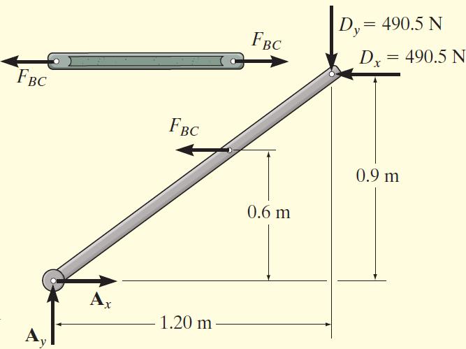
35 Example 6.21 The frame shown below supports the 50-kg cylinder. Determine the horizontal and vertical components of reaction at A and the force at C. 35

36 36
Chapter 6: Structural Analysis
 Chapter 6: Structural Analysis Goals and Objectives Determine the forces in members of a truss using the method of joints Determine zero-force members Determine the forces in members of a truss using the
ENG202 Statics Lecture 13, Sections
 ENG202 Statics Lecture 13, Sections 6.1-6.3 Simple Truss -A truss is a structure of slender members (Elements) joined together at their end points (Joints). -Elements consist of wooden struts or metal
Chapter Objectives. To show how to determine the forces in the members of a truss using: the method of joints and the method of sections.
 Structural Analysis Chapter Objectives To show how to determine the forces in the members of a truss using: the method of joints and the method of sections. Chapter Outline Two-force members Planar (Simple)
Structure composed of slender members joined together at their end points.
 STRUCTURAL ANALYSIS Truss Structure composed of slender members joined together at their end points. The members commonly used in construction consist of wooden struts or metal bars. Examples Simple Truss
Engineering Mechanics Statics. 8. Structural Analysis
 Mechanical Systems Engineering _ 2016 Engineering Mechanics Statics 8. Structural Analysis Dr. Rami Zakaria Simple Trusses Structural Analysis A truss is a structure composed of slender members joined
Equilibrium. Of a Rigid Body
 Equilibrium Of a Rigid Body 1 Objectives 1. To develop the equations of equilibrium for a rigid body. 2. To introduce the concept of the free-body diagram for a rigid body. 3. To show how to solve rigid
Truss: Types and Classification. Theory of Structure - I
 Truss: Types and Classification Theory of Structure - I Lecture Outlines Common Types of Trusses Classification of Trusses Method of Joints Zero Force Members Method of Sections 2 TRUSS ANALYSIS A truss
Statics Chapter 6 Structural Analysis Eng. Iqbal Marie Hibbeler, Engineering Mechanics: Statics,13e, Prentice Hall
 Statics Chapter 6 Structural Analysis Eng. Iqbal Marie iqbal@hu.edu.jo Hibbeler, Engineering Mechanics: Statics,13e, Prentice Hall 6.1 Simple Trusses 6.1 Simple Trusses truss structure composed of straight,
3 Simple and Compound Trusses Simple Truss: a truss whose number of members is given by m = 2j 3, where m = no. of members and j = no. of joints. (For
 2 TRUSSES Learning Objectives 1). To identify zero-force members in a structure. 2). To recognize planar and space (i.e., three-dimensional) truss structures. 3). To understand the assumptions made in
CIVL 3121 Trusses - Introduction 1/8
 CIVL 3121 Trusses - Introduction 1/8 We will discuss the determinacy, stability, and analysis of three forms of statically determinate trusses: simple, compound, and complex. CIVL 3121 Trusses - Introduction
Chapter - 1. Analysis of Truss
 Chapter - 1 Analysis of Truss Dr. Rajesh Sathiyamoorthy Department of Civil Engineering, IIT Kanpur hsrajesh@iitk.ac.in; http://home.iitk.ac.in/~hsrajesh/ Simple Trusses A truss is a structure composed
UNIT -2 (A) BENDING MOMENT AND SHEAR FORCE DIAGRAM FOR BEAMS. MYcsvtu Notes.
 BENDING MOMENT AND SHEAR FORCE DIAGRAM FOR BEAMS. MYcsvtu Notes.") UNIT -2 (A) BENDING MOMENT AND SHEAR FORCE DIAGRAM FOR BEAMS Beam It is a structural member whose longitudinal dimension is large compared to the transverse dimension. The beam is supported along its length
UNIT -2 (A) BENDING MOMENT AND SHEAR FORCE DIAGRAM FOR BEAMS Beam It is a structural member whose longitudinal dimension is large compared to the transverse dimension. The beam is supported along its length
Chapter 3: Analysis of Statically Determinate Trusses PREPARED BY SHAMILAH
 Chapter 3: Analysis of Statically Determinate Trusses PREPARED BY SHAMILAH ANUDAI@ANUAR INTRODUCTION Truss is a structure composed of slender members joined together at their end points The joint connections
Engineering Mechanics. Trusses
 Engineering Mechanics Trusses Truss 2 Definition of a Truss A truss is an assembly of straight members connected at joints. No member is continuous through a joint. Most structures are made of several
ENGINEERING STRUCTURES
 ENGINEERING STRUCTURES In the previous chapter we have employed the equations of equilibrium in order to determine the support / joint reactions acting on a single rigid body or a system of connected members
Types of Structures and Loads
 Types of Structures and Loads THEORY OF STRUCTURES Asst. Prof. Dr. Cenk Üstündağ Asst. Prof. Dr. Cenk Ustundag E-mail: ustunda1@itu.edu.tr Room Nr: 103 Web: http://web.itu.edu.tr/ustunda1 Course Content
DEPARTMENT OF ARCHITECTURE ABUBAKAR TAFAWA BALEWA UNIVERSITY, BAUCHI ARC 615: ADVANCED BUILDING STRUCTURES LESSON 4: VECTOR ACTIVE STRUCTURAL SYSTEMS
 DEPARTMENT OF ARCHITECTURE ABUBAKAR TAFAWA BALEWA UNIVERSITY, BAUCHI ARC 615: ADVANCED BUILDING STRUCTURES LESSON 4: VECTOR ACTIVE STRUCTURAL SYSTEMS 4.1 Introduction 4.2 Structural concept of planar trusses
ENR202 Mechanics of Materials Lecture 1A Slides and Notes
 Slide 1 Copyright Notice Do not remove this notice. COMMMONWEALTH OF AUSTRALIA Copyright Regulations 1969 WARNING This material has been produced and communicated to you by or on behalf of the University
Introduction to Structural Analysis TYPES OF STRUCTURES LOADS AND
 AND Introduction to Structural Analysis TYPES OF STRUCTURES LOADS INTRODUCTION What is the role of structural analysis in structural engineering projects? Structural engineering is the science and art
Chapter 6 ANALYSIS OF STRUCTURES
 hapter 6 NLYSIS OF STRUTURES truss is a structure consisting of straight members connected at their extremities only. The members being slender and unable to support lateral loads, all the loads must be
Spaghetti Bridge Design Project
 Spaghetti Bridge Design Project EI 2018 Contents 1 Project Overview..................................... 1 2 Introduction........................................ 1 3 Theory and Online Simulator.............................
15.2 Approximate Analysis of a Continuous Beam for Gravity Load
 15.2 Approximate Analysis of a Continuous Beam for Gravity Load Figure 15.1 Location of points of inflection and shear and moment curves for beams with various idealized end conditions 1 15.2 Approximate
How Beams Work, I. Statics and Strength of Materials
 How Beams Work, I Statics and Strength of Materials HOW BEAMS WORK Beams work by transferring transverse loads along their length to their supports primarily by resisting a force called internal bending
INDETERMINACY AND STABILITY. Old Little Belt Bridge Little Belt Strait Denmark
 INETERMINAY AN STABILITY Old Little Belt Bridge Little Belt Strait enmark Static Indeterminancy To solve a truss using only the equations of equilibrium, the truss must be statically determinate. For a
three equilibrium and planar trusses Equilibrium Equilibrium on a Point Equilibrium on a Point balanced steady resultant of forces on a particle is 0
 ELEMENTS OF RHITETURL STRUTURES: FORM, EHVIOR, N ESIGN R. NNE NIHOLS SPRING 2014 lecture three Equilibrium balanced steady resultant of forces on a particle is 0 X equilibrium and planar trusses X = Equilibrium
Structural Analysis. Method of Joints. Method of Pins
 Structural Analysis / Method of Pins "This professor would make a good parking lot a6endant. Tries to tell you where to go, but you can never understand him." Trusses Trusses are common means of transferring
Approximate Analysis of Statically Indeterminate Structures
 Approximate Analysis of Statically Indeterminate Structures Every successful structure must be capable of reaching stable equilibrium under its applied loads, regardless of structural behavior. Exact analysis
5.4 Analysis for Torsion
 5.4 Analysis for Torsion This section covers the following topics. Stresses in an Uncracked Beam Crack Pattern Under Pure Torsion Components of Resistance for Pure Torsion Modes of Failure Effect of Prestressing
Chapter 3: Torsion. Chapter 4: Shear and Moment Diagram. Chapter 5: Stresses In beams
 Chapter 3: Torsion Chapter 4: Shear and Moment Diagram Chapter 5: Stresses In beams Torsion Torsion or Torque, T, put simply, is referred to as a twisting moment. θ The derived formulas are: Where: Torsional
Example of a modelling review Roof truss
 Example of a modelling review Roof truss Iain A MacLeod The Structure Figure gives an elevation and connection details for a roof truss. It is supported at each end on masonry walls. The trusses are at
PORTAL FRAMES 1.0 INTRODUCTION
 36 PORTAL FRAMES 1.0 INTRODUCTION The basic structural form of portal frames was developed during the Second World War, driven by the need to achieve the low - cost building envelope. Now they are the
Method of Joints. Method of Joints. Method of Joints. Method of Joints. Method of Joints. Method of Joints. CIVL 3121 Trusses - Method of Joints 1/5
 IVL 3121 Trusses - 1/5 If a truss is in equilibrium, then each of its joints must be in equilibrium. The method of joints consists of satisfing the equilibrium equations for forces acting on each joint.
Plane Truss Stiffness Matrix
 ecture : Trusses & Grids tiffness Method Plane Truss tiffness Matri The distinguishing feature of a plane truss is that loads are applied in the plane of the structure whereas in a space truss they are
Chapter 2: Strain. Chapter 3: Torsion. Chapter 4: Shear and Moment Diagram
 Chapter 2: Strain Chapter 3: Torsion Chapter 4: Shear and Moment Diagram Strain - Is defined as change in length per unit length, simply put it is unit deformation L Stress and Strain Exist concurrently
Sabah Shawkat Cabinet of Structural Engineering 2017
 3.1-1 Continuous beams Every building, whether it is large or small, must have a structural system capable of carrying all kinds of loads - vertical, horizontal, temperature, etc. In principle, the entire
E APPENDIX. The following problems are intended for solution using finite element. Problems for Computer Solution E.1 CHAPTER 3
 E APPENDIX Problems for Computer Solution The following problems are intended for solution using finite element analysis software. In general, the problems associated with Chapters 3, 4, and 9 can be solved
Question Paper Code : 11410
 Reg. No. : Question Paper Code : 11410 B.E./B.Tech. DEGREE EXAMINATION, APRIL/MAY 2011 Fourth Semester Mechanical Engineering ME 2254 STRENGTH OF MATERIALS (Common to Automobile Engineering and Production
The problems in this guide are from past exams, 2011 to 2016.
 CE 311 Exam 1 Past Exam Problems, 2011 to 2016 Exam 1 (14% of the grade) THURSDY, 9/21 7 TO 9:30PM. OPTIONL Q& SESSION WED. 9/20, 8PM. COVERGE: LESSONS 1 TO 9 Exam is designed for 2 hours, but a maximum
MECHANICS OF MATERIALS
 Lecture Notes: Dr. Hussam A. Mohammed Al- Mussiab Technical College Ferdinand P. Beer, E. Russell Johnston, Jr., and John T. DeWolf Introduction Concept of Stress The main objective of the study of mechanics
 VALLIAMMAI ENGINEERING COLLEGE DEPARTMENT OF MECHANICAL ENGINEERING QUESTION BANK CE 6306 - STRENGTH OF MATERIALS UNIT I STRESS STRAIN DEFORMATION OF SOLIDS PART- A (2 Marks) 1. What is Hooke s Law? 2.
Jerome J. Connor Susan Faraji. Fundamentals of Structural. Engineering. ^ Springer
 Jerome J. Connor Susan Faraji Fundamentals of Structural Engineering ^ Springer Contents Part I Statically Determinate Structures 1 Introduction to Structural Engineering 3 1.1 Types of Structures and
Trusses. 4.1 Introduction
 P T R Trusses 4 4.1 Introduction truss is a structural element composed of a stable arrangement of slender interconnected bars (see ig. 4.1a). The pattern of bars, which often subdivides the truss into
1.Axial Force, Shear Force and Bending Moment:
 1 TRIBHUVAN UNIVERSITY INSTITUTE OF ENGINEERING PULCHOWK CAMPUS (Pulchowk, Lalitpur) Subject: Strength of Materials(II/I) (Tutorial ) 1.Axial Force, Shear Force and Bending Moment: 1. Draw AFD, SFD and
Graphic truss analysis. Graphic truss analysis Copyright Prof Schierle
 Graphic truss analysis Graphic truss analysis Copyright Prof Schierle 2011 1 Truss examples Oakland Bay Bridge Truss joists Graphic truss analysis Copyright Prof Schierle 2011 2 Stadium roof Milan Airport
Comparison between Seismic Behavior of Suspended Zipper Braced Frames and Various EBF Systems
 Comparison between Seismic Behavior of Suspended Zipper Braced Frames and Various EBF Systems A. Niknam 1, A. Sharfaei 2 1- Assistant Professor, Civil Engineering Faculty, University of Science & Technology,
(a) Pin-Pin P cr = (b) Fixed-Fixed P cr = (d) Fixed-Pin P cr =
 Pin-Pin P cr = (b) Fixed-Fixed P cr = (d) Fixed-Pin P cr =") 1. The most critical consideration in the design of rolled steel columns carrying axial loads is the (a) Percent elongation at yield and the net cross-sectional area (b) Critical bending strength and axial
1. The most critical consideration in the design of rolled steel columns carrying axial loads is the (a) Percent elongation at yield and the net cross-sectional area (b) Critical bending strength and axial
CHAPTER 2. Design Formulae for Bending
 CHAPTER 2 Design Formulae for Bending Learning Objectives Appreciate the stress-strain properties of concrete and steel for R.C. design Appreciate the derivation of the design formulae for bending Apply
The Static Analysis of the Truss
 American Journal of Mechanical Engineering, 2016, Vol. 4, No. 7, 440-444 Available online at http://pubs.sciepub.com/ajme/4/7/38 Science and Education Publishing DOI:10.12691/ajme-4-7-38 The Static Analysis
Design of Steel Structures Prof. S.R.Satish Kumar and Prof. A.R.Santha Kumar
 2.6 Portal frames Portal frames are the most commonly used structural forms for single-storey industrial structures. They are constructed mainly using hot-rolled sections, supporting the roofing and side
STRUCTURAL ANALYSIS Using Classical and Matrix Methods
 STRUCTURAL ANALYSIS Using Classical and Matrix Methods Fourth Edition Jack C. McCormac Clemson University 8 O 7 2 O O 7 John Wiley and Sons, Inc. Table of Contents DEDICATION PREFACE xiii vii PART ONE:
Lectures Notes (Steel I - CT122) Higher technological institute 10 th of Ramadan city Dr. Essam Abd Elaty Mohamed Amoush.
 Higher technological institute 10 th of Ramadan city Dr. Essam Abd Elaty Mohamed Amoush.") Introduction A truss is a structural system constructed of linear members forming triangular patterns. The members are assumed to be straight and connected to one another by frictionless hinges. All loading
Introduction A truss is a structural system constructed of linear members forming triangular patterns. The members are assumed to be straight and connected to one another by frictionless hinges. All loading
Indeterminate Structures. Architecture 4.440
 Indeterminate Structures Architecture 4.440 Outline! Introduction! Static Indeterminacy! Support Conditions! Degrees of Static Indeterminacy! Design Considerations! Conclusions Forces in the Legs of a
Page 1 of 46 Exam 1. Exam 1 Past Exam Problems without Solutions NAME: Given Formulae: Law of Cosines: C. Law of Sines:
 NAME: EXAM 1 PAST PROBLEMS WITHOUT SOLUTIONS 100 points Tuesday, September 26, 2017, 7pm to 9:30 You are allowed to use a calculator and drawing equipment, only. Formulae provided 2.5 hour time limit This
Shear Wall Sample Problem
 Shear Wall Sample Problem A long by high concrete block masonry shear wall, reinforced with 4 No. 20 bars (, as shown in the figure below, is subjected to a factored axial load of (including the self-weight)
VALLIAMMAI ENGINEERING COLLEGE
 VALLIAMMAI ENGINEERING COLLEGE DEPARTMENT OF CIVIL ENGINEERING CE6603: DESIGN OF STEEL STRUCTURES QUESTION BANK UNIT I: INTRODUCTION PART-A 1. List the various types of connections used for connecting
Behavioural Analysis of Lattice Bridge by Using ANSYS
 Behavioural Analysis of Lattice Bridge by Using ANSYS K.Suganthi 1, K. Sachidanandam 2 PG Student, Department of Civil Engineering, Starlion College of Engg and Tech, Thanjavur, Tamilnadu, India 1 Assistant
CHAPTER 1. Introduction
 CHAPTER 1 Introduction In the past it was common practice to teach structural analysis and stress analysis, or theory of structures and strength of materials as they were frequently known, as two separate
CH. 9 WOOD CONSTRUCTION
 CH. 9 WOOD CONSTRUCTION PROPERTIES OF STRUCTURAL LUMBER Grading Load carrying capacity effected by: - Size and number of knots, splits & other defects - Direction of grain - Specific gravity of wood Grading
Hours / 100 Marks Seat No.
 17422 21314 4 Hours / 100 Seat No. Instructions (1) All Questions are Compulsory. (2) Answer each next main Question on a new page. (3) Illustrate your answers with neat sketches wherever necessary. (4)
Code No: R Set No. 1
 Code No: R059210303 Set No. 1 II B.Tech I Semester Regular Examinations, November 2006 MECHANICS OF SOLIDS ( Common to Mechanical Engineering, Mechatronics, Metallurgy & Material Technology, Production
Full file at
 ink full download: Solution Manual for Mechanics of Materials 7th Edition by eer Johnston DeWolf and Mazurek https://digitalcontentmarket.org/download/solution-manual-for-mechanics -of-materials-7th-edition-by-beer-johnston-dewolf-and-mazurek/
Ce 479 Reinforced Masonry Fall 2005
 INTRODUCTION TO STRUCTURAL DESIGN OF REINFORCED MASONRY In the preceding lecture on structural design of masonry, we have seen examples of unreinforced masonry bearing walls. In bearing walls, when the
Optimum Dimensions of Suspension Bridges Considering Natural Period
 IOSR Journal of Mechanical and Civil Engineering (IOSR-JMCE) e-issn: 2278-1684,p-ISSN: 2320-334X, Volume 6, Issue 4 (May. - Jun. 2013), PP 67-76 Optimum Dimensions of Suspension Bridges Considering Natural
Structural Considerations for Trusses
 Introduction Structural Considerations for Trusses L0 L1 L3 L4 L5 L6 L7 Pratt Truss 1 Truss Types Three types of trusses in Alberta: Pony trusses Through trusses Deck trusses Traffic loads are transferred
ST7008 PRESTRESSED CONCRETE
 ST7008 PRESTRESSED CONCRETE QUESTION BANK UNIT-I PRINCIPLES OF PRESTRESSING PART-A 1. Define modular ratio. 2. What is meant by creep coefficient? 3. Is the deflection control essential? Discuss. 4. Give
EFFECTS OF INTERACTION BETWEEN JOINT SHEAR AND BOND STRENGTH ON THE ELAST-PLASTIC BEHAVIOR OF R/C BEAM-COLUMN JOINTS
 EFFECTS OF INTERACTION BETWEEN JOINT SHEAR AND BOND STRENGTH ON THE ELAST-PLASTIC BEHAVIOR OF R/C BEAM-COLUMN JOINTS Hitoshi SHIOHARA 1 ABSTRACT The effects of the interaction between (a) joint shear force
MAHALAKSHMI ENGINEERING COLLEGE TIRUCHIRAPALLI
 MAHALAKSHMI ENGINEERING COLLEGE TIRUCHIRAPALLI - 621213. QUESTION BANK WITH ANSWER DEPARTMENT: CIVIL SEMESTER: 06 SUBJECT CODE /NAME: CE 2352/DESIGN OF STEEL STRUCTURES YEAR: III UNIT II TENSION MEMBER
PRESTRESSED CONCRETE STRUCTURES UNIT I INTRODUCTION THEORY AND BEHAVIOUR
 BASIC CONCEPTS: PRESTRESSED CONCRETE STRUCTURES UNIT I INTRODUCTION THEORY AND BEHAVIOUR A prestressed concrete structure is different from a conventional reinforced concrete structure due to the application
CHAPTER 5 FINITE ELEMENT MODELLING
 53 CHAPTER 5 FINITE ELEMENT MODELLING 5.1 GENERAL Reinforced concrete structures are largely employed in engineering practice in a variety of situations and applications. In most cases these structures
Stay Tuned! Practical Cable Stayed Bridge Design
 midas Civil Stay Tuned! Practical Cable Stayed Bridge Design 2017 Francesco Incelli I. Introduction II. Modeling of the cable-stayed bridge a. Bridge wizard b. Girder Cross Section III. Nonlinear Effect
Members Subjected to Flexural Loads
 Members Subjected to Flexural Loads Introduction: In many engineering structures members are required to resist forces that are applied laterally or transversely to their axes. These type of members are
Effect of beam dimensions on structural performance of wide beam-column joints
 Effect of beam dimensions on structural performance of wide beam-column joints J.S. Kuang 1) and *Wing Shan Kam 2) 1), 2) Department of Civil and Environmental Engineering, Hong Kong University of Science
Class Exercise-1 Truss Structure & Stability
 Class Exercise-1 Truss Structure & Stability 1) How many bars do you need to make a simplest stable truss? a) 4 b) 3 c) 5 d) 0 2) The figure below shows three frame structure A, B, C respectively. The
Analysis of Statically Determinate Structures. W.M.Onsongo. 11~1~~ii~1 ~il~~i~i~',r,~jrll. Nairobi University Press
 Analysis of Statically Determinate Structures W.M.Onsongo 11~1~~ii~1 ~il~~i~i~',r,~jrll 04965208 Nairobi University Press CONTENTS Preface xiii CHAPTER INTRODUCTION I 1.1 Structures 1.2 Loads 1.3 Analysis
Trusses. Giacomo Boffi.
 Analysis of Design of http://intranet.dica.polimi.it/people/boffi-giacomo Dipartimento di Ingegneria Civile Ambientale e Territoriale Politecnico di Milano October 18, 2017 Analysis of Design of Historical
Experimental Study on Post Buckling Behaviour of Steel Plate Girder
 GRD Journals- Global Research and Development Journal for Engineering Volume 1 Issue 8 July 2016 ISSN: 2455-5703 Experimental Study on Post Buckling Behaviour of Steel Plate Girder Rohit V. Khobaragade
SHEAR BEHAVIOR OF RC DEEP BEAMS WITH SOLID CIRCULAR CROSS SECTION UNDER SIMPLY SUPPORTED CONDITION AND ANTI-SYMMETRIC MOMENT
 SHEAR BEHAVIOR OF RC DEEP BEAMS WITH SOLID CIRCULAR CROSS SECTION UNDER SIMPLY SUPPORTED CONDITION AND ANTI-SYMMETRIC MOMENT Koji MATSUMOTO (Tokyo Institute of Technology) Moe YONEHANA (Kajima Corporation)
Nonlinear Buckling of Prestressed Steel Arches
 Nonlinear Buckling of Prestressed Steel Arches R. Giles-Carlsson and M. A. Wadee Department of Civil and Environmental Engineering, Imperial College London, Exhibition Road, London SW7 2AZ, UK June 22
UNIT I SIMPLE STRESSES AND STRAINS, STRAIN ENERGY
 SIDDHARTH GROUP OF INSTITUTIONS :: PUTTUR Siddharth Nagar, Narayanavanam Road 517583 QUESTION BANK (DESCRIPTIVE) Subject with Code: Year & Sem: II-B.Tech & I-Sem Course & Branch: B.Tech - ME Regulation:
ARCH 331. Study Guide for Final Examination
 ARCH 331. Study Guide for Final Examination This guide is not providing answers for the conceptual questions. It is a list of topical concepts and their application you should be familiar with. It is an
Subject with Code: Strength of Materials(16CE104) Course& Branch: B. Tech - CE Year &Sem : II-B. Tech &I-Sem Regulation: R16
 Course& Branch: B. Tech - CE Year &Sem : II-B. Tech &I-Sem Regulation: R16") SIDDHARTH INSTITUTE OF ENGINEERING &TECHNOLOGY:: PUTTUR (Approved by AICTE, New Delhi & Affiliated to JNTUA, Anantapuramu) (Accredited by NBA & Accredited by NAAC with A Grade) (An ISO 9001:2008 Certified
SIDDHARTH INSTITUTE OF ENGINEERING &TECHNOLOGY:: PUTTUR (Approved by AICTE, New Delhi & Affiliated to JNTUA, Anantapuramu) (Accredited by NBA & Accredited by NAAC with A Grade) (An ISO 9001:2008 Certified
Unit II Shear and Bending in Beams
 Beams and Bending Unit II Shear and Bending in Beams 2 Marks questions and answers 1. Mention the different types of supports. i. Roller support ii. Hinged support iii. Fixed support 2. Differentiate between
Introduction to Bridges
 Introduction to Bridges Clinton Pandaraoan Civil Engineer Japan Engineer District February 5, 2010 US Army Corps of Engineers Scope Definition of a bridge Examples of the different types of bridges Principles
Portal frame PLASTIC DESIGN OF PORTAL FRAMES
 Portal frame Monday, November 9, 2015 9:23 AM PLASTIC DESIGN OF PORTAL FRAMES Introduction This section covers a number of features of plastic design of portal frames to BS 5950-1. The frame is analysed
Note. Floor beams can also be made from wooden beams put through the holes in the longitudinal beam and boards nailed to it.
 Assembly instructions for HAKI IV These assembly instructions are designed for the construction of sectional HAKI IV scaffolding approved in accordance with the technical standards TP 73-05-60/020/83.
CHAPTER 1 INTRODUCTION
 CHAPTER 1 INTRODUCTION 1.0. GENERAL Modern civilization relies upon the continuing performance of civil engineering infrastructure ranging from industrial building to power station and bridges. For the
Contents. Tables. Notation xii Latin upper case letters Latin lower case letters Greek upper case letters Greek lower case letters. Foreword.
 Tables x Notation xii Latin upper case letters Latin lower case letters Greek upper case letters Greek lower case letters xii xiv xvi xvi Foreword xviii 1 Introduction 1 1.1 Aims of the Manual 1 1.2 Eurocode
NODIA AND COMPANY. GATE SOLVED PAPER Civil Engineering Design of Steel Structure. Copyright By NODIA & COMPANY
 No part of this publication may be reproduced or distributed in any form or any means, electronic, mechanical, photocopying, or otherwise without the prior permission of the author. GATE SOVED AER Civil
Idealization of Structures and Loads
 Idealization of Structures and Loads To analyze a structure by the methods that are described in these notes it must be idealized. By utilizing the idealized structural model the deformations and internal
TRUSSES. Church Truss Vermont Timber Works
 TRUSSES Church Truss Vermont Timber Works Truss Action Consider a loaded beam of rectangular cross section as shown on the next page. When such a beam is loaded, it is subjected to three internal actions:
Name of the Lab Course (Basic Structural Analysis Lab)
") Lebanese University Faculty of Engineering II LAB Civil Engineering Department Name of the Lab Course (Basic Structural Analysis Lab) Instructors: Wassim Elias, M2R. Civil Eng. Youssef Kassouf, Civil Eng.
Lebanese University Faculty of Engineering II LAB Civil Engineering Department Name of the Lab Course (Basic Structural Analysis Lab) Instructors: Wassim Elias, M2R. Civil Eng. Youssef Kassouf, Civil Eng.
R13. II B. Tech I Semester Regular/Supplementary Examinations, Dec MECHANICS OF SOLIDS (Com. to ME, AME, AE, MTE) Time: 3 hours PART-A
 Time: 3 hours PART-A") SET - 1 II B. Tech I Semester Regular/Supplementary Examinations, Dec - 2015 MECHANICS OF SOLIDS (Com. to ME, AME, AE, MTE) Time: 3 hours Max. Marks: 70 Note: 1. Question Paper consists of two parts (Part-A
SET - 1 II B. Tech I Semester Regular/Supplementary Examinations, Dec - 2015 MECHANICS OF SOLIDS (Com. to ME, AME, AE, MTE) Time: 3 hours Max. Marks: 70 Note: 1. Question Paper consists of two parts (Part-A
UNIVERSITY OF BOLTON WESTERN INTERNATIONAL COLLEGE FZE. BEng (HONS) CIVIL ENGINEERING SEMESTER ONE EXAMINATION 2018/2019
 CIVIL ENGINEERING SEMESTER ONE EXAMINATION 2018/2019") OCD030 UNIVERSITY OF BOLTON WESTERN INTERNATIONAL COLLEGE FZE BEng (HONS) CIVIL ENGINEERING SEMESTER ONE EXAMINATION 2018/2019 ADVANCED STRUCTURAL ANALYSIS AND DESIGN MODULE NO: CIE6001 Date: Tuesday 8
OCD030 UNIVERSITY OF BOLTON WESTERN INTERNATIONAL COLLEGE FZE BEng (HONS) CIVIL ENGINEERING SEMESTER ONE EXAMINATION 2018/2019 ADVANCED STRUCTURAL ANALYSIS AND DESIGN MODULE NO: CIE6001 Date: Tuesday 8
Masonry and Cold-Formed Steel Requirements
 PC UFC Briefing September 21-22, 2004 Masonry and Cold-Formed Steel Requirements David Stevens, ARA Masonry Requirements Composite Construction Masonry is often used in composite construction, such as
LESSON 8: COLUMN BUCKLING I
 "lways, there is football." Cristal Choi, former exchange student who lived in Prof. Kurtz s house, explaining all merican holidays to a new exchange student. LESSON 8: COLUMN BUCING I Wednesday, September
BRACING REQUIREMENTS FOR LATERAL STABILITY
 BRACING REQUIREMENTS FOR LATERAL STABILITY By John J. Zahn, 1 M. ASCE ABSTRACT: The forces induced in braces depend on the magnitude of initial imperfections (lateral bending and twist) and magnitude of
Analysis of Shear Wall Transfer Beam Structure LEI KA HOU
 Analysis of Shear Wall Transfer Beam Structure by LEI KA HOU Final Year Project report submitted in partial fulfillment of the requirement of the Degree of Bachelor of Science in Civil Engineering 2013-2014
Estimate the endurance strength in MPa if the rod is used in rotating bending.
 348 Mechanical Engineering Design PROBLEMS Problems marked with an asterisk (*) are linked to problems in other chapters, as summarized in Table 1 1 of Sec. 1 16, p. 24. Problems 6 1 to 6 63 are to be
CIVL473 Fundamentals of Steel Design
 CIVL473 Fundamentals of Steel Design CHAPTER 3 Design of Beams Prepared By Asst.Prof.Dr. Murude Celikag DESIGN OF STRUCTURAL ELEMENTS 3. Beams in Buildings 3.1. Laterally Restrained Beams Restrained beams
Lessons learned: 3.2.Stability concepts
 The contractor did not follow the contract requirement to limit the advancement of the uppermost lifted slabs to not more than three levels above the level of completed shear walls. Also, he did not provide