CHAPTER 8 Nuclear Plant Systems
|
|
|
- Roderick Powers
- 5 years ago
- Views:
Transcription
1 1 CHAPTER 8 Nuclear Plant Systems prepared by Dr. Robin Chaplin Summary: This chapter deals with the main components of a CANDU nuclear power plant. It follows the general path of energy production from the nuclear reactor to the electrical generator with descriptions of the systems and equipment essential for the purpose of generating thermal energy, transferring heat and converting heat into mechanical and then electrical energy. Some key auxiliary systems are included where these are an essential part of the energy processes as are the basic control systems which maintain stable operational conditions and ensure safety of the plant. This chapter leads into Chapter 9 which describes how a typical CANDU plant operates. Table of Contents 1 Introduction General Configuration Nuclear Reactor General Arrangement Calandria Arrangement Moderator Temperature Control Moderator Reactivity Control Core Shielding Reactor Control Systems and Devices Fuel Configuration Fuel Channel Conditions Fuel Handling Heat Transport System General Arrangement Heat Transport Pumps Pressurizer Inventory Control System Shutdown Cooling System Partial Boiling in CANDU Reactors Pressure and Level Effects Temperature and Nuclear Considerations... 27
2 2 The Essential CANDU 4 Steam Generators Steam Generator Function Steam Generator Conditions Pressure Control Level Control Comparison of CANDU and PWR Systems Steam System General Arrangement Steam Bypass System Condenser Steam Discharge Valves Turbine Control Valves Steam Turbine General Arrangement Turbine Cylinders Turbine Rotors Turbine Blading Turbine Sealing Principles Turbine Seals Steam Sealing System Turbine Bearings Bearing Lubrication Reheating and Feed Heating Steam Separators and Reheaters Deaerator Feedwater Heaters Condenser General Arrangement Electrical Generator Generator Rotor Generator Stator Excitation System Generator Systems Power Transmission Generator Main Connections Generator Circuit Breakers Generator Transformers Transformer Connections Problems References and Bibliography Acknowledgements... 58
3 Nuclear Plant Systems 3 List of Figures Figure 1 Reactor vault and assembly... 6 Figure 2 Feeder tube assembly on reactor face... 7 Figure 3 Moderator cooling and purification system... 8 Figure 4 CANDU 6 reactor assembly Figure 5 Reactor cross section Figure 6 Reactor longitudinal section Figure 7 Reactor plan view Figure 8 Shutdown System 2 (SDS2) Figure 9 37-element fuel bundle Figure 10 Reactor face with fuelling machine Figure 11 Typical fuelling machine and bridge Figure 12 Orientation of fuelling machine with respect to reactor Figure 13 Simplified heat transport and moderator circuits Figure 14 Diagrammatic arrangement of figure-of-eight heat transport system Figure 15 Heat transport purification and feed system Figure 16 Shutdown cooling system Figure 17 Steam generator for CANDU system Figure 18 Temperature profiles in steam generator Figure 19 Steam generator for PWR system Figure 20 Steam generator for CANDU system Figure 21 Steam and feedwater system for a CANDU reactor Figure 22 Main steam system (Point Lepreau) (courtesy of NB Power) Figure 23 High pressure turbine cross section for nuclear unit (courtesy of Eskom) Figure 24 Low pressure turbine cross section for nuclear unit (courtesy of Eskom) Figure 25 Electrical generator for a large turbine (courtesy of Siemens) Figure 26 Construction of a 900 MW steam turbine for a nuclear unit (courtesy of Eskom) Figure 27 Spring mounted labyrinth seal to accommodate shaft deflection Figure 28 Principle of operation of LP turbine shaft seal (courtesy of NB Power) Figure 29 Turbine steam sealing system Figure 30 Fixing points for turbine rotors and casings (courtesy of NB Power) Figure 31 Turbine generator shaft catenary Figure 32 Turbine lubricating oil system Figure 33 Deaerator and deaerator storage tank (courtesy of NB Power) Figure 34 Feedwater heater with integral drain cooler (courtesy of NB Power) Figure 35 Condenser longitudinal section (courtesy of NB Power) Figure 36 Condenser cross section (courtesy of NB Power) Figure 37 Insertion of rotor into stator of generator (courtesy of NB Power) Figure 38 Arrangement of three single phase generator transformers... 55
4 4 The Essential CANDU List of Tables Table 1 CANDU fuel characteristics Table 2 Fuel channel parameters (CANDU 6) Table 3 Steam generator conditions (CANDU 6) Table 4 Turbine generator conditions (CANDU 6)... 33
5 Nuclear Plant Systems 5 1 Introduction 1.1 General Configuration Specific units in a typical CANDU nuclear plant include a nuclear reactor in which heat is generated by nuclear fission, a heat transport system to convey this heat from the reactor to the steam cycle, a steam generator in which steam is generated, a steam system to convey steam from the steam generator to the steam turbine, a steam turbine where available heat energy is converted into mechanical energy, a condenser where unavailable heat energy is rejected to the cooling water system, a steam reheating and feedwater heating system to improve cycle efficiency, an electrical generator to convert mechanical energy into electrical energy, and an electrical system to generate electrical energy for distribution to consumers. To balance the flow of energy through these components and to regulate plant output, a control system is required. Each of these major systems will be described in this chapter. All thermal reactors have four important components: fuel, moderator, coolant, and control elements. The moderator is that part of the nuclear reactor where neutrons are reduced in energy to increase the probability of fission when they re-enter the fuel. Spacing of the fuel assemblies within the moderator is therefore of key importance. Heat must be removed by the coolant from the fuel assemblies at a high rate without making the fuel sustain excessive temperatures. This is achieved by having multiple small diameter fuel rods (elements) in one fuel assembly. These two requirements dictate the general reactor configuration. A unique aspect of the CANDU reactor is the horizontal arrangement of fuel channels within the reactor calandria. These channels contain the fuel bundles and are surrounded by the heavy water moderator, whereas heavy water coolant flows through the channels. Heat is generated in the nuclear reactor, and electricity is produced by the electrical generator. The production and discharge of this energy must be perfectly balanced. The steam generator is the key component for maintaining this balance, that is, the rate of steam generation must match the rate of steam flow to the steam turbine, or vice versa. Any change in these two energy flows will immediately be reflected as a change in steam pressure in the steam generator. Therefore, steam pressure is a key control parameter for the entire plant under all operating conditions. 2 Nuclear Reactor 2.1 General Arrangement For all CANDU reactors, the horizontal fuel channels are arranged in a square array across the reactor face, as shown in Figure 1. The calandria, which contains the moderator at essentially atmospheric pressure, contains axial tubes in a similar square array to accommodate the pressurized fuel channels or pressure tubes, which in turn contain the fuel bundles and the primary system coolant. Figure 2 shows a close-up view of the feeder pipes conveying coolant to and from the pressure tubes at one end of the reactor.

6 6 The Essential CANDU Figure 1 Reactor vault and assembly

7 Nuclear Plant Systems Calandria Arrangement Figure 2 Feeder tube assembly on reactor face The calandria contains the moderator for the reactor. It consists essentially of a horizontally mounted cylindrical tank containing many horizontal tubes in a square array. Pressure tubes containing fuel and coolant are fitted inside the calandria tubes, with a small annular gas filled space to provide heat insulation. This annular space is maintained by garter springs which resist sagging of the pressure tubes and thus minimize the risk of contact with the calandria tubes. The gas used is carbon dioxide because it has low thermal conductivity, shows little tendency to promote corrosion, and does not produce significant activation products. The carbon dioxide is circulated in the annular space to cool it and to monitor it for any leakage from the calandria and pressure tubes. The calandria contains heavy water as moderator, which fills the space between the calandria tubes. The spacing of the calandria tubes and hence the fuel channels is greater than optimum with respect to neutron moderation, with the result that the reactor is over-moderated. 2.3 Moderator Temperature Control Heat is generated in the heavy water moderator by the neutron moderating process, where the kinetic energy of the neutrons is converted into heat energy, and by absorption of gamma radiation. Both these processes intensify with a rise in reactor power. Heat is also transferred to the moderator through the carbon dioxide in the annular space between the pressure tubes and calandria tubes. This process is largely independent of reactor power because the fuel channel temperature is fairly constant at all power levels. The total amount of heat generated in and transferred to the moderator is approximately 5% of total reactor heat production. This heat must be removed to maintain the desired temperature in the moderator. The moderator temperature is maintained between 60 C and 65 C by an external cooling system, as illustrated in Figure 3. This system includes circulating pumps and heat exchangers, which reject heat to the service water system. Although the relatively large temperature difference between the reactor coolant and the moderator induces some heat loss, the rela-
8 8 The Essential CANDU tively cool moderator can provide some measure of cooling to the fuel in the event of a loss of coolant accident and the coincident failure of the emergency coolant injection system. Because the reactor s configuration makes it over-moderated, any void formation within the moderator would cause an increase in reactivity, leading to unstable reactivity conditions. Hence, it is desirable to maintain an adequate margin below boiling conditions. Figure 3 Moderator cooling and purification system The moderator temperature has an effect on the reactivity of the reactor as its temperature rises from ambient conditions to operating conditions during reactor warm-up. For equilibrium fuel conditions, that is, a mix of used and new fuel that arises after several months of continuous refuelling, the temperature coefficient of reactivity is positive, meaning that the reactivity increases by about 4 mk as the temperature goes from 30 C to 70 C. This phenomenon is due mainly to two factors. One is the lower density of the moderator at higher temperatures, resulting in less neutron absorption. The other is the increased fission cross section of plutonium as the increase in temperature takes the neutron energy into a resonance peak of Pu Moderator Reactivity Control To control moderator reactivity, soluble poisons are added to the heavy water at appropriate concentrations under certain operating conditions through a moderator liquid poison addition system. This system consists of mixing tanks for boron and gadolinium, also shown in Figure 3, where the solutions are formulated, as well as flow transmitters at the circulating pump inlet to measure the amount entering the moderator system.
9 Nuclear Plant Systems 9 Both gadolinium and boron have strong neutron absorbing isotopes, namely Gd-155, Gd-157, and B-10. They gradually lose their ability to absorb neutrons as neutrons are absorbed to form a heavier isotope. The burnout rate for boron is slower than that of gadolinium, making it more suitable for longer term operations such as compensation for reactivity loss due to fuel burnup. When a reactor is charged with new fuel, the excess reactivity from the fuel can be balanced by a certain concentration of boron. As the fuel burns up and neutron absorbing fission products are produced, the effectiveness of the boron decreases, making it possible to maintain reasonably constant reactivity with naturally small adjustments. The burnout rate for gadolinium is faster than that of boron, and therefore it is more suitable for short term reactivity adjustments such as those necessary during xenon transients. The xenon concentration in the fuel is lower during periods of low load and builds up following a large power increase. Gadolinium can compensate for this and burns out at a rate roughly corresponding to xenon buildup. Gadolinium can also be used to compensate for a lack of xenon in the reactor during an outage to ensure that the reactor will remain subcritical. The shutdown system, which will be described later, injects liquid poison directly into the moderator in the event of certain reactor trips. Gadolinium is used at sufficient concentration to ensure an immediate reduction in reactivity to well below critical conditions. Upon reactor restart, it must be removed by the moderator purification system. Gadolinium is easily removed by ion exchange resins, whereas boron, being a weaker ion, is not easily removed. This makes gadolinium better suited for use in the shutdown system, but it still takes several hours to remove it and almost as long as the ensuing outage due to xenon poisoning. A moderator purification system, also shown in Figure 3, is connected to the moderator cooling system to maintain heavy water purity and to remove or adjust the concentration of soluble poisons such as gadolinium or boron which may have been introduced for shutdown purposes or to assist in reactivity control. The non-active soluble poison (after neutron absorption) must be removed to maintain the general purity of the moderator. The purification system has strainers to remove particulate material such as resin fines from the system, followed by mixed bed ion exchange columns to remove dissolved material in the form of positive and negative ions. 2.5 Core Shielding The reactor core is shielded at the ends by end shields and around the periphery by a thermal shield to absorb neutron and gamma radiation which would otherwise create excessive radiation fields at the reactor faces and high temperatures in the calandria structure. The shields contain water which is circulated and cooled. The end shields contain steel balls as well to ensure sufficiently low radiation fields during routine maintenance shutdowns. The combination of water and steel balls is very effective in attenuating both neutron and gamma radiation. 2.6 Reactor Control Systems and Devices Heavy water is a very weak neutron absorber, which is advantageous with regard to fuel utilization. To compensate for reactivity changes in the fuel, the absorption properties of the moderator can be modified by adding a soluble neutron absorber in small concentrations. Gadolinium and boron both have strong neutron absorbing isotopes, namely Gd-155, Gd-157, and B-10. These can be added through the liquid poison system and removed through the moderator purification system using ion exchangers. Light water is a stronger neutron absorber than heavy
10 10 The Essential CANDU water, and therefore the concentration of light water in the heavy water moderator must be limited to avoid excessive neutron absorption. The normal isotopic concentration of D 2 O in the moderator is 99.5%. Light water, however, can be conveniently used as a control device within the reactor, where its volume in vertical tubes can be varied. Reactor power is controlled and maintained at the required level by several devices which absorb neutrons and thereby control the nuclear fission process. These systems and devices are: Liquid poison in moderator Liquid zone control absorbers Mechanical rod control absorbers Mechanical rod adjusters. In addition, a complete reactor shutdown can be achieved by operating one or both of the following devices in addition to those listed above: Mechanical rod shut-off absorbers (Shutdown System 1) Liquid poison injection system (Shutdown System 2). Appropriate signals to operate the control systems are obtained from neutron flux detectors within the core and ion chambers alongside the core as well as from other sensors in the steam system and turbine generator. The main control devices are shown as part of the reactor assembly in Figure 4. The control devices described below are generally applicable to CANDU 6 reactors. The same design philosophy applies to other CANDU reactors, but the number of devices may be different if the reactor core is of different size. In a CANDU 6 reactor core, there are 26 in-core vertical flux detectors and 7 in-core horizontal flux detectors. Twelve vertically installed detectors provide flux information to Shutdown System 1, while three horizontal flux detectors supply flux data to Shutdown System 2. The remaining vertical flux detectors send information to the liquid zone control absorbers and the solid control rod absorbers. All these in-core flux detectors can provide data for three dimensional flux mapping of the reactor core. Figure 5, Figure 6, and Figure 7 show three orthogonal views of a CANDU 6 reactor. These show the relative positions and arrangement of various components and devices.

11 Nuclear Plant Systems 11 Figure 4 CANDU 6 reactor assembly


12 12 The Essential CANDU Figure 5 Reactor cross section


13 Nuclear Plant Systems 13 Figure 6 Reactor longitudinal section
14 14 The Essential CANDU Figure 7 Reactor plan view
15 Nuclear Plant Systems Moderator Poison Addition System Liquid poison such as boron or gadolinium can be added to the moderator to adjust reactor reactivity. Because these are both neutron absorbers, they reduce neutron efficiency and hence adversely affect fuel utilization. However, as described earlier, their use is necessary under certain transient conditions to maintain reactivity within regular control limits. Such conditions arise when a reactor is started with a new charge of fresh fuel, when a significant amount of fresh fuel is added, and during large increases in load when xenon transients need to be accommodated Liquid zone control absorbers Critical reactivity balance is mostly and predominantly maintained by the six liquid zone control absorbers located vertically within the reactor core interspersed among the mechanical control absorbers, adjuster rods, and shut-off rods. These liquid zone absorbers contain light water in two or three separate sections, forming a total of fourteen compartments. These separate and independent absorbers enable spatial control of neutron flux. Light water absorbs neutrons more strongly than heavy water and acts like a control rod as light water is added or removed through inlet and outlet pipes, where a difference in flow rate will vary the level. Helium gas is maintained above the light water, and the difference in pressure between the inlet and outlet, at the bottom and top of the water column respectively, indicates the level of light water. The quantity of water in each compartment is controlled by automated valves receiving signals from the flux detectors through the control computers of the reactor regulating system Mechanical rod control absorbers Besides the liquid zone control absorbers, there are also four mechanical control absorbers made from a variety of alloys, predominantly cadmium encased in stainless steel. These absorbers adjust the flux level when a greater reactivity rate or depth than can be provided with the liquid zone control absorbers is required. They can bring about a fast reactor power reduction such as a reactor stepback. They may be driven in or out of the core at variable speed or dropped into the core by the release of a clutch. The design of these solid control absorbers is virtually identical to that of the shut-off rods described below Mechanical rod adjusters Adjuster rods are used in the reactor to optimize the neutron flux profile for reactor power, compensate for fuel burnup, and provide excess reactivity to overcome Xenon-135 surges following a power reduction. CANDU reactors are designed to develop full power when these adjuster rods are fully inserted into the reactor core. There are 21 adjuster rods arranged in three rows vertically between the other control devices. The adjuster elements are raised or lowered individually by winching drives similar to those described for the shut-off rods, except that these adjusters do not fall into the reactor in the event of a shutdown signal from the flux detectors because they would normally be fully inserted during normal operation. When the adjusters are fully withdrawn, the reactivity gain is about 16 mk, which is sufficient to overcome minor xenon transients during power manoeuvering.
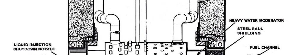
16 16 The Essential CANDU Mechanical rod shut-off absorbers The signals received from the flux detectors or other plant indicators, which are routed to Shutdown System 1 (SDS1), control a system of 28 vertical shut-off rods. These shut-off rods are composed of cadmium and stainless steel absorber elements and are used to shut the reactor down under normal and emergency conditions. When these rods are inserted into the core, they are aided by perforated guide tubes made of zirconium alloy that are open to the pressure of the moderator. These shut-off rods are inserted into or withdrawn from the core by means of a stainless steel cable which is wound on a drum in the rod drive mechanism. This drum is driven by an electric motor with an electromagnetic friction clutch. When a shut-off signal is received, the clutch de-energizes, and the shut-off rods fall into the reactor core inside the zirconium alloy guide tubes under the influence of gravity. While the clutch is energized, the shut-off rods can be driven into or out of the reactor core by the electric drive motor Liquid poison injection system This system, unlike the Moderator Poison Addition System, is a safety system as opposed to a control system. It injects a large quantity of soluble poison into the moderator to reduce reactivity drastically rather than adding a controlled amount to maintain reactivity at the required level. Shutdown System 2 (SDS2), as illustrated diagrammatically in Figure 8, is activated based on information received from the three horizontal in-core flux detectors or other plant indicators. The poison that is injected into the core is gadolinium nitrate dissolved in heavy water. This poison is contained in six tanks outside the reactor vault in an accessible area for routine maintenance. Each of the six poison tanks is connected to a nozzle pipe in the calandria by stainless steel pipes. These nozzle pipes are oriented horizontally in the reactor core, each with several orifice holes situated to provide maximum negative reactivity changes when the poison is injected. The nozzle pipes themselves are made of zirconium alloy. The gadolinium nitrate poison is injected into the core by helium under pressure. Pressurized helium in this tank is isolated from the poison tanks by triplicated quick-acting valves. When these valves are opened, the pressure forces the poison into the moderator very quickly. A ball in the poison tanks prevents blowthrough of helium gas and ensures that calandria pressure does not exceed its design value. SDS2 is typically capable of supplying at least 50 mk of negative reactivity worth, although a negative reactivity of 30 mk is considered adequate to bring about complete and rapid shutdown. This system acts as a backup to SDS1 and should be activated only in the event of a failure of SDS1 or if the initiating event is so severe or so fast that SDS1 has not arrested the transient. Because liquid poison is injected into the moderator, quick recovery from such a trip is not possible. In the original CANDU design concept, it was decided that there should be two independent and different shutdown systems operated from different sources and configured differently. To achieve this objective, the SDS1 and SDS2 systems inject negative reactivity in different ways and even in different orientations within the reactor, that is, one vertically and one horizontally.
17 Nuclear Plant Systems 17 Figure 8 Shutdown System 2 (SDS2) 2.7 Fuel Configuration In most CANDU reactors, the individual fuel bundles have 37 fuel elements, each containing a stack of natural uranium dioxide fuel pellets. Within each fuel element are approximately 30 fuel pellets, giving an effective stack length of 480 mm. The fuel elements are held in place by end plates which are perforated to enable coolant to flow axially and are prevented from contacting one another or the pressure tube by spacers. The element sheaths are made of zircaloy to minimize neutron absorption. There are 12 fuel bundles in each fuel channel of the CANDU 6 reactor. The configuration of the reactor with horizontal fuel channels enables the reactor to be refuelled while on load and also facilitates partial refuelling of a single channel because the fuel bundles do not have to be linked together as in a vertical channel. A 37element fuel bundle is shown in Figure 9, while Table 1 gives details of a 37-element fuel bundle.


18 18 The Essential CANDU Figure 9 37-element fuel bundle Table 1 CANDU fuel characteristics Fuel Type Sintered natural uranium dioxide Pellets Cylindrical with concave dished ends Number in Elements 30 Elements per Bundle 37 Bundles per Fuel Channel 12 Pellet Diameter mm Pellet Stack Length 480 mm Cladding Zircaloy-4 Cladding Outside Diameter mm Bundle Outside Diameter mm Bundle Overall Length 495 mm 2.8 Fuel Channel Conditions A temperature rise takes place along the fuel channel from the inlet to the outlet until saturation conditions are reached, after which the temperature remains approximately constant. This temperature rise is not linear because the rate of temperature rise depends upon the local rate of heat release and hence on the neutron flux, which drops off towards both the inlet and outlet of the channel. The most severe fuel conditions occur where both the heat flux and coolant temperature are high. This occurs normally somewhat downstream of the channel midpoint. Typical fuel channel conditions are given in Table 2.
19 Nuclear Plant Systems 19 Table 2 Fuel channel parameters (CANDU 6) Fuel Channel Material Zirconium-Niobium Alloy Inside Diameter mm Wall Thickness 4.19 mm Inlet Pressure MPa (a) Outlet Pressure MPa (a) Inlet Temperature 267 C Outlet Temperature 312 C Maximum Coolant Flow 24 kg/s Average Coolant Flow 20 kg/s 2.9 Fuel Handling Short term reactivity changes occur continuously during normal operation due to load changes or to minor transient conditions. Short term reactivity control is maintained in the reactor core by liquid zone control absorbers (for load changes) and adjuster rods (for transients). Long term reactivity changes occur slowly as fuel is used up and fission products accumulate in the fuel. Long term reactivity control is achieved through on-line refuelling to maintain constant reactivity while fuel is burned. By varying the frequency of refuelling in different areas of the reactor core, the flux and hence the power distribution can be very effectively and accurately controlled. The CANDU reactor with its horizontal fuel channels has a reactor face at each end, onto which two fuelling machines must attach while maintaining pressure and flow in the channel. Figure 10 shows a typical reactor face with a fuelling machine. This is a larger reactor with 480 fuel channels (Darlington) with a later design of fuelling machine than the one illustrated in Figure 11 and Figure 12. Fuel is inserted into and removed from the fuel channels by two remotely controlled fuelling machines which attach to the ends of a selected fuel channel. A general view of a typical fuelling machine (Pickering) as seen from the reactor side is shown in Figure 11. These fuelling machines are fully automatic and remotely controlled. The equipment itself consists of a fuelling machine mounted on a suspended carriage. The carriage travels on a track which can be raised or lowered by a gantry so that the fuelling machines can reach any fuel channel. Heavy water and electricity supplies are provided by a flexible catenary which connects the machine to the stationary auxiliary systems.

20 20 The Essential CANDU Figure 10 Reactor face with fuelling machine Figure 11 Typical fuelling machine and bridge The arrangement with respect to the reactor face is shown in Figure 12. By raising or lowering the gantry and traversing the carriage, the fuelling machine can reach any channel. When the gantry is at its lowest point, the machine can turn 90 in the horizontal plane, as shown by the dotted image, to receive new fuel or to discharge spent fuel in the service area. After
21 Nuclear Plant Systems 21 attachment to the reactor, the fuelling machines open the fuel channel and remove the shield plug. One fuelling machine carries the new fuel in its magazine, while the other machine at the opposite end of the fuel channel receives and stores spent fuel in its own magazine. Each magazine can revolve and has several slots, each of which can store two fuel bundles. Two new fuel bundles from the fuelling machine are inserted at the coolant inlet end, while two used bundles are removed at the coolant outlet end. Normally, depending on the particular CANDU design, eight bundles are changed during one channel refuelling. In this way, the two bundles at each end where the neutron flux is low spend twice as long in the reactor than those in the high flux zone in the middle. Flow through the channel is maintained, and the pressure difference so derived is used to move the bundles into the channel and to provide a driving force to facilitate their removal. Spent fuel is later transferred to the irradiated fuel bay, where it is stored under water. The average time taken to refuel one fuel channel is about two and one half hours, meaning that the refuelling process is almost continuous during normal working hours. Figure 12 Orientation of fuelling machine with respect to reactor New fuel is loaded directly into the magazine of the fuelling machine, but irradiated fuel must be remotely handled and transferred under shielded conditions to the irradiated fuel bay for interim storage during its initial cooldown period. 3 Heat Transport System 3.1 General Arrangement The fundamental function of the primary coolant circuit or heat transport system is to circulate the heavy water coolant and transport heat from the fuel elements to the steam system. The entire circuit consists of pumps, headers, feeder pipes, pressure tubes, and steam generators, as shown in Figure 13. In addition, there is a single pressurizer in the circuit. The coolant used in CANDU

22 22 The Essential CANDU reactors is heavy water to minimize neutron absorption. In the pressure tubes, the coolant flows are in opposite directions in adjacent tubes. Thus the coolant passes from the steam generators at one end of the reactor through half the tubes to the steam generators at the other end of the reactor and back again through the adjacent tubes. There are two steam generators and two heat transport pumps at each end of the reactor, and therefore the entire system is divided into two independent loops, with each serving half the reactor. They are linked by a balance pipe with restricting orifices so that the same pressure is maintained in each loop and only one pressurizer is required. This arrangement is illustrated diagrammatically in Figure 14. The advantage of this arrangement is that, in the event of a serious loss of coolant accident, only half the reactor will be affected initially, with minimum subsequent loss of coolant from the other half. Figure 13 Simplified heat transport and moderator circuits
23 Nuclear Plant Systems 23 Figure 14 Diagrammatic arrangement of figure-of-eight heat transport system As coolant leaves the reactor, it passes through the outlet feeder tubes on each reactor face and then to the respective headers. From here, it enters the U-tube steam generators situated at opposite ends of the reactor. In the steam generator, the pressurized heavy water exchanges heat with the light water on the steam side of the steam generator. The now cooled heavy water passes to the heat transport pumps, one for each steam generator, and returns to the reactor core through headers and inlet feeder tubes at each end of the reactor. The heat transport system serves to remove heat from the reactor under both power producing and shutdown conditions. The flow is maintained by the heat transport pumps under most conditions, but with the steam generators located above the reactor, natural circulation is possible under shutdown conditions. Pressure in the fuel channels is maintained at about 10 MPa at the outlet end, and the coolant is generally subcooled, although above about 90% full load power, some boiling occurs in the most highly rated fuel channels. At full power, the steam exit quality is typically 3% to 5%, which gives a voidage of 26% to 37% at 10 MPa. This steam is subsequently mixed with subcooled coolant from the lower rated channels to give conditions very close to saturation at the steam generator inlet though the flow to the lower rated channels is somewhat reduced to minimize the difference in exit quality. The heat transport pumps are driven by electrical motors. Should power supply to the motors fail, forcing a reactor trip, the pumps have sufficient built-in inertia to run down over a period of two to three minutes. This allows sufficient time for natural circulation or thermosiphoning to be established. Pressure in the heat transport circuit is maintained by a pressurizer in most CANDU reactors. This operates at saturation conditions and is approximately half filled with liquid, with the remaining space containing vapour. It is connected to the heat transport system by a pipe which is long enough to maintain its temperature independently of the heat transport system. This enables the reactor outlet header pressure to be controlled regardless of the heat trans
24 24 The Essential CANDU port system temperature. There is a feed-and-bleed system to inject or extract heavy water from the heat transport system. This enables the correct inventory to be maintained under transient conditions such as start-up and shutdown and to compensate for leakage. It also enables external clean-up and chemical treatment of coolant under lower pressure and temperature conditions, as well as recovery of leakage and upgrading of heavy water. 3.2 Heat Transport Pumps Four heat transport pumps circulate heavy water coolant around the system. They are vertical single stage centrifugal pumps driven by induction motors. Mechanical seals prevent leakage of reactor coolant. These seals are supplied with cooled heavy water, some of which leaks outwards and some into the pump, thus maintaining the correct operating temperature at the pump seals and preventing loss of reactor coolant. In the CANDU 6, the pumps each draw approximately 5 MW of electrical power, giving a total of 17 MW of energy input to the heat transport system. This input is used to raise the temperature and pressure of the reactor coolant system during warm-up from cold shutdown conditions. 3.3 Pressurizer The pressurizer maintains pressure in the heat transport system by maintaining a cushion of vapour above the heavy water in the lower half. Pressure can be reduced by venting vapour at the top or by spraying water into the vapour space and can be increased by heating the water with electric heaters at the bottom. During normal operation, the heaters generally operate periodically because the pressurizer loses heat naturally to its surroundings. Some plants rely on venting vapour only to reduce pressure and do not have water sprays. Level in the pressurizer is ramped up as the temperature of the heat transport system increases to accommodate partially the thermal expansion of the reactor coolant during power raising. Under cold shutdown conditions, the pressurizer is normally isolated from the heat transport system to maintain an elevated temperature in it. During warm-up, the pressurizer is isolated from the heat transport system, meaning that the system is in the so-called solid mode of operation as opposed to the normal mode of operation where the pressurizer is connected to the system. In this solid mode, pressure control is by feed and bleed action where the flow rate of heavy water in and out of the system is adjusted to maintain the correct pressure. In the normal mode, the feed and bleed action of the inventory control system adjusts the coolant inventory by maintaining the pressurizer level at its set-point. To avoid over-pressure conditions in the heat transport system, pressure relief valves on the reactor outlet headers discharge excess coolant to the degasser condenser of the inventory control system. If this action is insufficient to alleviate the over-pressure condition, the control system will step back the reactor to a lower power level, and if this still does not reduce pressure sufficiently, it will trip the reactor. Note that the steam generators serve as a heat sink for the heat transport system, and therefore reducing pressure and hence temperature in the steam generators will have the effect of reducing temperature in the heat transport system, with a resulting reduction in pressure as well.
25 Nuclear Plant Systems Inventory Control System The inventory control system serves to maintain pressure in the heat transport system when the pressurizer is isolated and to maintain level in the pressurizer under normal operating conditions. It also serves as a reserve source of heavy water to compensate for minor leakage and to maintain heavy water purity by means of the purification system. This requires continuous bleeding and feeding of heavy water so that it can be treated appropriately. Figure 15 shows a diagrammatic arrangement of a typical inventory control system for purification and feeding of coolant to the heat transport system. The heavy water is at high temperature and pressure upon leaving the system. Therefore, it must be treated under either high pressure or low pressure conditions. Figure 15 shows a system with high pressure purification to minimize pressure reduction and pumping back to pressure, but the feed and bleed operation and heavy water storage are at lower pressure, with the coolant initially passing through a degasser before being pumped back into the system. Furthermore, the ion exchange resins cannot withstand high temperatures, and therefore cooling to about 50 C is required before purification. It is advantageous to use the heat removed from the bleed flow to heat the feed flow before it is returned to the heat transport system. Therefore, the system includes interchangers as well as service water coolers. Figure 15 Heat transport purification and feed system 3.5 Shutdown Cooling System When the reactor is shut down, decay heat is removed through the steam generators and the
26 26 The Essential CANDU steam reject system. If the reactor must be cooled down, the steam reject system can function well until the steam generator pressure drops so low that the volume flow rate through the steam reject or condenser steam discharge valves is insufficient for effective cooling. This occurs at about 150 C to 165 C. Operation of the shutdown cooling system is initiated before this stage is reached and removes heat directly from the heat transport system. A typical system is shown in Figure 16. It can handle about 10% to 15% of the main system flow and is capable of removing 1% to 3% of reactor full power heat. Figure 16 Shutdown cooling system 3.6 Partial Boiling in CANDU Reactors Although CANDU reactors have pressurized primary coolant systems where boiling is suppressed, local boiling does occur in the highest rated fuel channels. The steam produced is subsequently partially condensed when it mixes with coolant from lower rated fuel channels. This has some definite advantages. Slight boiling enhances the heat transfer coefficient on the fuel element surfaces, thus promoting heat transfer. It also increases the heat removal capacity of the coolant because the enthalpy of the mixture leaving the fuel channel is increased. Thirdly, after mixing with coolant from nonboiling fuel channels, the average coolant exit temperature is at saturated conditions with some vapour present, or at least closer to saturated conditions than it would be if there were no boiling. This means that the coolant entering the steam generators is at as high a temperature as possible considering the prevailing pressure in the system. The degree of boiling is limited to about 3% by weight to avoid flow instability problems and to maintain a sufficient margin to avoid dryout of the fuel elements. This small amount of steam is nevertheless about 25% by volume at prevailing pressures and is not insignificant with regard to reactivity effects because it does provide slight positive feedback.
27 Nuclear Plant Systems 27 This occurs because the fuel channel spacing is greater than optimum, resulting in overmoderation of neutrons. Voidage reduces the moderating effect and reduces neutron absorption, creating conditions closer to the optimum. 3.7 Pressure and Level Effects Pressure in the heat transport system must be maintained within certain limits to avoid overpressure conditions if it is too high or excessive vapour production and pump cavitation if it is too low. Although these problems can be easily controlled by venting some vapour (if the pressure is too high) or heating the liquid (if the pressure is too low), the required liquid level in the pressurizer must also be maintained, and therefore level and pressure are interdependent, although independently controlled. Level changes occur during warm-up and shutdown and also during power increases and decreases due to changes in average coolant temperature. As the average coolant temperature rises and increases the coolant volume, the excess is pushed into the pressurizer, causing an increase in level. During warm-up from the cold shutdown condition to the hot standby condition, as much as 60 m3 may be displaced due to swelling. The resulting rise in pressurizer level is accommodated by the feed and bleed system, which temporarily increases the extraction rate. With an increase in power, there is additional swelling due to a further increase in average temperature and the onset of limited vapour generation. Note that the steam generator steam pressure and hence steam temperature are kept constant, and therefore, to achieve an increased heat transfer rate, the temperature difference between the primary side reactor coolant and the secondary side water and steam must increase. Hence, the average reactor coolant temperature in the steam generator must increase, which causes an increase in its specific volume. This last effect accounts for about 10 m3 to 20 m3 displacement of reactor coolant. This is accommodated by ramping up the setpoint of the pressurizer level control system. Power transients therefore do not force a change in inventory and have minimal impact on the feed and bleed system. 3.8 Temperature and Nuclear Considerations Temperature and voidage both affect reactor reactivity. Generally, temperature causes a change in reactivity as the coolant goes from cold shutdown conditions to hot shutdown conditions. This leads to a negative coefficient of reactivity with new fuel and a slight positive coefficient with equilibrium fuel. During normal operation, when some boiling occurs in the fuel channels, the effect of voidage becomes significant. Because so little moderator is present between the closest fuel rods, there is little initial moderating of neutrons, and the fast fission factor increases. Moreover, with higher neutron energies, there is less probability of resonance absorption. Both these effects contribute to an increase in reactivity, giving a positive coefficient of reactivity as voidage increases. In the overall design, these effects are compensated for by other negative coefficients and by the reactor regulating system. During operation of the primary system, the heavy water isotopic concentration is slowly downgraded due to leakage and chemical treatment. The increase in light water increases neutron absorption. This reduces neutron economy and results in an increase in fuel usage. Moreover, with reduced heavy water isotopic concentration, additional reactivity worth must be added to maintain criticality. In the event of a loss of coolant accident and channel void formation, the increase in positive reactivity will be greater. To ensure that this will be controllable, there is a lower limit on heavy water isotopic concentration. This is generally in the range of 97.5% to 98.5%, while the normal value is around 99.5%.
28 28 The Essential CANDU There is also an upper limit on fuel channel heavy water isotopic concentration. It should always be less than the calandria heavy water isotopic concentration by a small margin. This is necessary because, in the event of an in-core loss of coolant accident, the possible penetration of channel coolant into the calandria may displace moderator containing neutron poison. The concentration of light water must therefore be sufficient to absorb at least as many neutrons as the poison and light water in the moderator would have absorbed before the accident. 4 Steam Generators 4.1 Steam Generator Function The steam generator serves the primary function of supplying energy to the turbine for power production. It also serves the secondary function, but one most important from the safety point of view, of removing energy from the reactor. Immediately after a reactor trip, the decay heat of the fission products amounts to some 7% of full power heat production. The most practical method of removing this heat is through the steam generator. Hence, it is necessary to maintain a certain minimum water inventory in the steam generator and to ensure that adequate reserve supplies of feed water are available. The steam generator also serves as the main controlling link between the nuclear reactor and the turbine generator. The power flows of the primary coolant system and the secondary steam system must be balanced under all conditions. Any imbalance will cause an accumulation or a depletion of the total heat content of the steam generator inventory, which in turn will result in a rise or fall of steam pressure. Steam pressure is therefore a key parameter in plant control. The steam generator separates the primary coolant circuit from the secondary steam circuit and hence prevents radioactive products in the reactor coolant from entering the steam turbine and the feedwater heating system. This barrier is an additional safety feature and also minimizes the area over which radiation monitoring is required. As an example of the importance of the steam generator in performing an essential safety function, consider a nuclear plant with an electrical output of 600 MW. The reactor produces approximately 1800 MW of heat, and the decay heat amounts to about 120 MW immediately after a reactor trip from full power. This is a substantial amount, the removal of which must be guaranteed under all conditions, including for a certain period after shutdown, because it takes almost 10 hours for this heat to fall to a tenth of the initial value, that is, about 12 MW for the example given. Separate smaller capacity heat removal systems can handle these lesser heat flows on their own after the reactor has been shut down for some time, although they are often put into service while the steam generators are still handling the major portion of the heat flow. 4.2 Steam Generator Conditions The primary coolant enters the steam generators at nearly saturated conditions or saturated with some steam present. As shown in Figure 17, it passes through the inverted U-tubes at high velocity, resulting in high heat transfer coefficients on the inside of the tubes. Water on the outside of the tubes is at lower pressure and therefore boils under the prevailing conditions. This boiling results in high heat transfer coefficients on the outside of the tubes and induces a strong upward convection current which promotes recirculation of the water in the steam generator, while the steam produced is separated for use in the steam system. A feature of the
29 Nuclear Plant Systems 29 steam generator is the high heat transfer rate across the tubes compared with other types of heat exchangers. This high heat transfer rate leads to a large temperature difference across the tubes themselves, as well as in the boundary layer on each side of the tubes. Typically, the temperature differences in the two boundary layers and across the tube itself are all approximately the same. This means that the temperature drop across the tubes is about one third of the total temperature difference and cannot be disregarded as in some other heat exchangers such as the main condenser. Ideally, heat exchangers should be counter-flow to minimize the temperature difference between the hot and cold fluids. This is not possible with a phase change on one side of the heat exchanger. Steam is therefore generated on the secondary side at a somewhat lower temperature than the primary coolant inlet temperature. To maintain good thermodynamic efficiency, a partial counter-flow arrangement is achieved by the subcooled feed water, which enters the steam generator being passed through a preheater section before mixing with the saturated recirculating water. The preheater receives heat from the primary coolant just before its exit to minimize large temperature differences across which heat is transferred. The temperature profile along the length of the tubes is shown in Figure 18. Table 3 gives typical operating parameters of a CANDU 6 steam generator. Figure 17 Steam generator for CANDU system
30 30 The Essential CANDU Figure 18 Temperature profiles in steam generator Table 3 Steam generator conditions (CANDU 6) Type Vertical U-Tube with Preheater Number of Steam Generators 4 Heat Transfer Area (each) 3127 m Heat Transferred (total) 2064 MW Coolant Flow Rate (total) 7600 kg/s Coolant Inlet Temperature 312 C Coolant Outlet Temperature 266 C Steam Flow Rate (total) 1047 kg/s Feedwater Flow Rate 959 kg/s Reheater Return Flow Rate 89 kg/s Blowdown Flow Rate 1 kg/s Steam Outlet Pressure 4.69 MPa (a) Steam Outlet Temperature 260 C Feedwater Inlet Temperature 187 C Reheater Drain Inlet Temperature 258 C Pressure Control Any mismatch in the rate of heat flow to the steam generator on the primary side or from it on the secondary side will result in a change in steam pressure. Control of steam generator pressure is therefore achieved by reactor heat input or steam turbine output. It therefore becomes part of overall plant control, which is covered in Chapter 10.
31 Nuclear Plant Systems 31 A change in steam pressure in the steam generator affects steam generator water level. A reduction in pressure causes the expansion of existing vapour bubbles in the water and additional evolution of vapour due to the lower saturation conditions. The result is a rise in water level or swelling of the inventory. An increase in pressure has the opposite effect, shrinking of the inventory. These are transient conditions, and the original conditions are restored when steam pressure returns to normal. A change in load also affects the level. A simultaneous increase in reactor output and turbine generator load will not affect steam pressure, but will result in increased evolution of vapour within the water space. This will in turn cause a rise in water level or swelling of the inventory. The opposite will cause shrinking of the inventory. These are steady state effects, and hence there is a relationship between load and level. The level control system takes this into account by ramping up the level set-point as load increases. 4.4 Level Control Considering the effects described above, it is evident that level control is a critical aspect of steam generator performance. A change in pressure is usually induced by a change in load. An increase in turbine load, for example, will cause a drop in steam pressure as more steam is drawn from the system. This will cause transient swelling, and the rise in water level would indicate that less feed water is required, when in fact more will be required to meet the increased steam demand. Inventory control by level only will result in excessive level fluctuations. To solve this problem, the control system compares steam flow and feedwater flow and combines the result with the level indication. Such a three element level control system gives better control in normal operation, while single element level control using level measurement only is satisfactory for low power operation. 4.5 Comparison of CANDU and PWR Systems A comparison of steam generators as used in the PWR and CANDU systems is instructive in comparing their relative merits. Both are very similar in construction. Natural circulation drives the flow upwards over the tube bundle and downwards through a peripheral annulus after separation of the steam, which occurs in cyclonic separators. Above the cyclones are steam dryers, so that the steam leaving the steam generator has a moisture content of only about 0.25%. The fundamental difference between the PWR and CANDU steam generators is shown in Figure 19 and Figure 20 respectively. The feed water enters the PWR steam generator at the top near the normal water level and mixes with the recirculating water before passing down the annulus. The recirculating water is therefore somewhat subcooled when it re-enters the tube bundle. In the CANDU steam generator, the feed water enters at the bottom and passes over the outlet side of the tube bundle before mixing with the recirculating water. The feed water is thus preheated by the exiting coolant in a counter-flow arrangement, while the recirculating water within the steam generator is not subject to subcooling. This is an advantage from a thermodynamic point of view because hot and cold fluids are not mixed, but limits must be placed on the feedwater temperature range to avoid thermal shock to the steam generator tubes, and a deaerator with hot storage capabilities is essential. In the PWR, this is not a problem because thorough mixing occurs before the water enters the tube bundle. This means that the PWR steam generator can receive feed water over a much wider temperature range and that hot storage of feed water is not essential.
32 32 The Essential CANDU Figure 19 Steam generator for PWR system Figure 20 Steam generator for CANDU system
33 Nuclear Plant Systems 33 5 Steam System 5.1 General Arrangement From the steam generators, steam is piped to the high pressure turbine at a temperature of about 260 C, as shown in Figure 21, where it expands partially in the high pressure turbine, yielding some useful work. The steam is then put through a separator and reheater, where moisture in the steam is removed in a cyclonic separator and the steam brought up to higher temperature in a heat exchanger using steam directly from the steam generator. The superheated steam is then passed in parallel through two or three low pressure turbines where the remaining energy is removed from the expanding steam. The steam is then passed to a condenser where it is condensed. This condensate is pumped through low pressure feedwater heaters where it is preheated. It is then passed through a deaerator and pumped through high pressure feedwater heaters for further preheating. It re-enters the steam generator at a temperature of about 180 C. Table 4 gives typical technical and operating parameters for a CANDU 6 steam turbine. Table 4 Turbine generator conditions (CANDU 6) Number of HP Cylinders 1 (double flow) Number of LP Cylinders 3 (double flow) Number of Moisture Separators 4 Number of Reheaters 2 Steam Flow Rate (total) 1047 kg/s Steam Flow Rate (turbine) 957 kg/s HP Steam Inlet Pressure 4.55 MPa (a) HP Steam Inlet Temperature 258 C LP Steam Inlet Pressure MPa (a) LP Steam Inlet Temperature 242 C Steam Exhaust Pressure MPa (a) (typical) Steam Exhaust Temperature 30 C (typical)
34 34 The Essential CANDU Figure 21 Steam and feedwater system for a CANDU reactor Control of steam flow is important to protect the steam generators as well as the steam turbine. Provision is therefore made to release excess steam to avoid over-pressure in the steam generators and to stop steam flow to the turbine if electrical output is terminated or if a component or system fails on the turbine generator. 5.2 Steam Bypass System The main steam system is somewhat more complex than that shown diagrammatically in Figure 21 because provision must be made to discharge excess steam when it is not required or cannot be used. It is advantageous to recover this steam, condense it, and return it to the feedwater system, but if this is not possible, it must be discharged to the atmosphere. Figure 22 shows the steam system for a CANDU 6 unit with the various valves to control steam flow under various conditions.
35 Nuclear Plant Systems 35 Figure 22 Main steam system (Point Lepreau) (courtesy of NB Power) As mentioned above, the steam generator has the important secondary function of removing heat from the reactor after a turbine trip. Under such circumstances, the excess steam must be diverted elsewhere. Excess steam may be vented to the atmosphere through atmospheric discharge valves. This, however, is wasteful, and it is better to recover the steam in the condenser and to reuse the condensate. All plants therefore have a steam bypass system to enable excess steam to be dumped to the condenser through the condenser steam discharge valves and recovered by the condensate system. The condenser bypass system is usually designed to accept the maximum quantity of steam that can be handled by the condenser to enable excess steam to be bypassed under a range of reactor operating conditions. In the event that the atmospheric discharge valves and condenser steam discharge valves are both inoperable, there are conventional boiler safety valves on the steam generators to enable discharge of excess steam. During plant start-up, the reactor load is increased progressively through a series of checks on its operation. During this time, it might not be desirable to run the turbine, and hence excess steam would be discharged to the condenser, bypassing the turbine. Another situation is a turbine trip or grid system disruption requiring a temporary rejection of load. Such a large load reduction would result in a buildup of neutron absorbing xenon in the
36 36 The Essential CANDU reactor to the extent that it would force a reactor shutdown. To avoid this situation, the reactor load must be maintained at about 60%. By dumping the equivalent quantity of steam into the condenser, reactor load can be maintained at a sufficiently high level to avoid xenon poisoning and a long term forced shutdown. Because the steam cycle has a thermal efficiency of about 30%, almost all the remaining 70% of heat input can be rejected to the environment through the condenser. The maximum heat rejection capabilities of the condenser therefore roughly match the minimum load required by the reactor to avoid excessive xenon buildup and reactor poisoning. 5.3 Condenser Steam Discharge Valves The condenser steam discharge valves open progressively to control steam generator pressure by discharging an appropriate amount of surplus steam. Under certain circumstances, when the turbine is unavailable and it is desirable to maintain load on a nuclear reactor to prevent poisoning out with xenon buildup, substantial quantities of steam may have to be discharged for an extended period. This steam enters the condenser space at high velocity and in a hot superheated condition. To avoid thermal damage to the condenser structure and tubes and to the condenser neck expansion joint, cool condensate is sprayed into the steam to cool it to normal condenser temperatures. Provision must also be made to avoid flow induced vibration due to the high velocities generated. A typical location of the steam discharge headers is shown in Figure 35 and Figure 36 in the section on the condenser later in this chapter. Certain limits are imposed on the operation of the condenser steam discharge valves. Under particular circumstances, the condenser steam discharge valves are prevented from opening and discharging steam. Circumstances leading to this are reduced condenser vacuum or high turbine load when the ability of the condenser to absorb additional thermal load is limited. 5.4 Turbine Control Valves The steam turbine has stop valves and governor valves on all high pressure turbine inlet pipes. The governor valves control the steam flow to the turbine and hence the turbine output, while the stop valves close in an emergency to stop all flow of steam to the turbine. In the event of a turbine trip, they operate together as a back-up to one another, but during a load rejection, the stop valves stay open. In addition, most turbines have stop valves and all have intercept valves on all the low pressure turbine inlet pipes to serve the same purpose with regard to the steam trapped in the moisture separator and reheater system. Expansion of this steam could accelerate the turbine generator to overspeed conditions if it were allowed to enter the low pressure turbine. Separate steam release valves enable this trapped steam to be released to the condenser. 6 Steam Turbine 6.1 General Arrangement Steam turbines consist essentially of a casing to which stationary blades are fixed on the inside and a rotor carrying moving blades on its periphery. The rotor is fitted inside the casing, with the rows of moving blades penetrating between the rows of fixed blades. Therefore, steam flowing through the turbine passes alternately through fixed and moving blades, with the fixed blades directing the steam at the correct angle for entry into the moving blades. Both casings
37 Nuclear Plant Systems 37 and rotors must be constructed to minimize damaging thermal stresses, and the moving blades must be fitted securely to the rotor to withstand high centrifugal forces. Where the rotor shaft passes through the ends of the casing, a seal is required to prevent steam leakage and air ingress. In addition, within the casing, seals are required to prevent steam from leaking around the blades rather than passing through them. Turbine seals are of the labyrinth type where there is no mechanical contact between fixed and rotating parts. Leakage is therefore not really eliminated, but merely controlled to minimal amounts. The rotor shafts are carried on bearings and are linked together and to the electrical generator. Bearings must be properly aligned to accommodate the natural gravitational bending of the shaft. Allowance must also be made for differential expansion between the rotors and the casings during thermal transients. Both must be free to expand without upsetting the alignment, while allowing the rotors to expand more quickly and to a greater degree than the casing. Lubrication is required for the bearings. Multiple pumps driven by alternative power sources ensure adequate lubrication under all operating circumstances. 6.2 Turbine Cylinders Typical units applicable to CANDU plants have a high pressure cylinder and three low pressure cylinders. These are designed to accommodate the increasing specific volume of the steam as it expands down to subatmospheric pressures. Provision is also made for steam quality improvement by reheating and for the extraction of partially expanded steam for feedwater heating. To withstand pressure, thick cylinder walls are required, but to minimize thermal stress, abrupt changes in thickness and asymmetrical arrangements should be avoided. This leads inevitably to smooth rounded profiles of the stress bearing components. In addition, uniform heating of components is desirable to avoid differential expansion and undue thermal stress. This requires sections of uniform thickness and provision for steam circulation within the casing, as shown in Figure 23, to promote uniform temperature changes, particularly during unit start-up. Steam access into and out of the cylinder must also be accommodated, which requires special nozzles and casing reinforcement in these areas. Furthermore, overall expansion of the components must be accommodated, and therefore the cylinders must be mounted on sliding pads with keys to maintain alignment. To assemble the turbine and to disassemble it for maintenance, the casing must be split in some way. The joint is normally horizontal so that the upper half can be removed, leaving the lower half in position along with the rotating parts. The high pressure turbine is fairly compact due to the low specific volume of steam at this point in the steam cycle. Provision is made to extract steam for feedwater heating and for steam circulation within the casing to promote uniform heating and cooling. Figure 23 shows the high pressure cylinder of a 900 MW turbine for a PWR, which has high pressure steam conditions fairly close to those of a CANDU reactor.


38 38 The Essential CANDU Figure 23 High pressure turbine cross section for nuclear unit (courtesy of Eskom) Low pressure turbines are very much larger because they must accommodate the increase in specific volume as the steam expands. Low pressure turbines are therefore of different construction. An inner casing supports the fixed blading and has annular channels through which steam is extracted for feedwater heating. Surrounding each entire low pressure turbine is an exhaust hood into which the exhaust steam flows before passing into the condenser below the turbine. Figure 24 shows the low pressure cylinder of a 900 MW turbine for a PWR which has low pressure steam conditions fairly close to those of a CANDU reactor. Figure 24 Low pressure turbine cross section for nuclear unit (courtesy of Eskom) Diaphragms carrying the fixed blades are fixed inside the turbine cylinders. Like the cylinder casings, they are split horizontally to enable assembly around the turbine rotor. Because there is a pressure drop across the fixed blades in both impulse and reaction turbines, sealing must be
39 Nuclear Plant Systems 39 provided between the diaphragms and the rotor to minimize steam leakage. In turbines with reaction blading, significant axial thrust is developed by the steam flow. Double flow turbines are normally used so that this axial thrust is balanced by opposing forces. Turbines with impulse blading do not develop this large thrust, but the low pressure blading near the turbine exhaust must have a reaction component due to the length of the blades. Therefore, all large low pressure turbines are double flow. 6.3 Turbine Rotors The moving blades are mounted on and transmit power to the turbine rotors. Their shafts are coupled together and drive the generator rotor. Rotors must be able to transmit the applied torque and to withstand the gravitational force due to their mass. As with casings, rotors are subject to high temperatures and must be built to minimize thermal stress during temperature transients. A certain degree of rigidity is important to minimize vibration during full speed operation as well as during run-up and shutdown. Rotors of small turbines are usually machined from solid forgings, but large turbines and especially low pressure turbines are usually built up from discs shrunk onto a stepped shaft. The blades are attached to the turbine rotors in various ways and in such a pattern as to minimize unbalanced forces. Even with close manufacturing tolerances, there is a slight mass variation between blades. The moment of each blade with respect to the shaft centre is measured and the blades arranged around the circumference to minimize out of balance forces and to ensure uniform stress on the turbine discs. Even so, some imbalance is inevitable, and the turbine rotor must be dynamically balanced, usually at full speed, in a specially designed tunnel or pit. The generator rotor is invariably the longest of the rotors making up the entire turbine generator. A typical generator is illustrated in Figure 25, which shows the rotor. The rotor carries the field coils which excite the stator coils to produce electric power. Because the field coils carry heavy currents, they must be sufficiently robust and well cooled. The individual current carrying bars must be well insulated and securely mounted to withstand centrifugal forces. Cooling is by hydrogen under pressure circulating through the bars. The hydrogen is driven by fans mounted on the rotor, which contribute to the full speed no-load frictional resistance felt by the machine. More frictional resistance arises from the shaft bearings of all rotors. The stator is also cooled by hydrogen and often by water passing through the windings as well. Electric power is produced at high voltage, and insulation must be designed accordingly.

40 40 The Essential CANDU Figure 25 Electrical generator for a large turbine (courtesy of Siemens) 6.4 Turbine Blading Turbine blades are either fixed or moving and are shaped so that energy transfer takes place by the impulse or reaction principle. The blade design is governed by the steam conditions in the turbine, the desired steam velocities and directions, and the steam forces on the blades. In addition, consideration must be given to geometrical limitations and dynamic forces arising from high speed turbine rotation. The moving blades in particular are subject to very high centrifugal forces and are sensitive to vibration induced by turbine rotation and steam flow. Figure 26 shows a large nuclear steam turbine under construction. This turbine receives saturated steam at 5.5 MPa from a pressurized water reactor, operates at 1500 revolutions per minute, and has a nominal rating of 900 MW. In the figure, the lower half of a diaphragm containing one row of fixed blades for one low pressure cylinder is seen being lowered into position. Also shown are the moving blades attached to the rotor of another low pressure cylinder. In the background is one complete rotor for a low pressure turbine. It is evident from this photograph that the fixed blades are securely fixed at both ends in a robust diaphragm. The moving blades, however, are attached only to the rotor discs and may or may not have tip shrouding or lacing wires to increase rigidity. Both tip shrouding and lacing wires are used in this machine and can be seen in the picture.

41 Nuclear Plant Systems 41 Figure 26 Construction of a 900 MW steam turbine for a nuclear unit (courtesy of Eskom) The design philosophy for fixed and moving blades is naturally different. All large turbines have pressure compounded impulse blading or reaction blading so that there is a pressure drop across the fixed blading. The blades must withstand this pressure drop, and if the design provides for a large diaphragm, as is usually the case in low pressure turbines, the blades must also support the pressure difference across the diaphragm. The blades may therefore be quite wide (as measured in the axial direction), especially towards the outer diameter. On the other hand, moving blades are subject to high centrifugal forces and have a slender shape decreasing in width towards the outer diameter. When steam expands below the saturation line, some condensation takes place, and the steam becomes wet. A very fine mist of droplets forms and passes over the blading, and some is deposited on the blades to create a film of water. This film is swept off the blades and entrained by the steam. The size of these entrained drops is governed by surface tension rather than by condensation phenomena. They are therefore somewhat larger than the original condensation droplets and, when travelling at high velocity, can damage any material on which they impinge. Being larger and heavier, they are also separated more easily from the main steam flow during changes in direction. When these larger drops are swept off the fixed blades, their velocity tends to be lower than that of the steam, and the moving blades tend to run into them at high speed. The impact of the drops on the blades (more accurately the blades on the drops) causes material erosion from the blades. Minute amounts of material are removed,

42 42 The Essential CANDU leaving a rough etched like surface. If severe, this material removal can change the blade profile and weaken the blade. After impact on the moving blades, the water film tends to be thrown off towards the periphery by centrifugal action. Turbine blades must be designed to withstand moisture erosion in the affected areas. This is done using inserts of hard erosion resistant material such as tungsten or stellite or by specialized heat treatment to harden the blades in selected areas. 6.5 Turbine Sealing Principles Steam turbines receive steam at high pressure and discharge it at high vacuum conditions. Provision must therefore be made to prevent steam from leaking out of the turbine where the steam pressure is high and air from leaking into the turbine where the steam pressure is below atmospheric. The turbine casing can be made steam tight with accurately machined flange joints, but where the rotating shaft passes through the stationary casing, leak tight joints cannot be made without direct contact between fixed and rotating parts. Similarly, within the turbine itself, there is a stepwise steam pressure drop through the various stages. Each diaphragm carrying the fixed blades must withstand a pressure differential and have seals around the hole through which the rotating shaft passes. In a reaction turbine, where there is a pressure drop across the moving blades as well, these must have seals around their periphery to reduce steam leakage around the top of the blades. Various types of glands have been devised, but large steam turbines all use the labyrinth type of seal. The distinct advantage of this type of seal is the lack of direct mechanical contact. Under normal circumstances, this eliminates mechanical friction and wear and heat buildup. The objective is not to eliminate leakage, but to reduce it to manageable proportions. Labyrinth seals are therefore designed to pass steam through the gap between the fixed and moving parts. Abnormal shaft deflection, however, can cause contact between the shaft and seals. The seals are therefore spring mounted so that they can be pushed back and are thin so that they can deform or wear away quickly in the event of contact to avoid overheating and damage to the turbine shaft. Figure 27 Spring mounted labyrinth seal to accommodate shaft deflection
43 Nuclear Plant Systems Turbine Seals Pressure in a turbine drops from the inlet to the exhaust, with the exhaust being under subatmospheric conditions. Moreover, as the turbine load changes, so does the steam pressure. The steam flow through the turbine is proportional to the inlet steam pressure. Therefore, as the turbine is throttled and steam flow reduced, the inlet steam pressure drops and, in the limit, will drop to condenser vacuum conditions under no flow. In any case, the entire steam space of the turbine is connected to the condenser, and at start-up, before steam is admitted to the turbine, this space throughout the turbine will be at the same pressure as the condenser, that is, very nearly a complete vacuum. Under these conditions, air will leak into the turbine through the shaft seals, creating difficulty in maintaining the proper vacuum conditions. To overcome this problem of air in-leakage, provision is made to supply low pressure steam to the shaft seals when they are subjected to subatmospheric internal pressures. This steam is fed into the seals in such a way that some leaks through the labyrinth rings into the turbine and some leaks through the opposite rings to the outside atmosphere, as shown in Figure 28. As long as steam flows outwards, air cannot enter the turbine against this flow, and the condenser is protected against air ingress. The steam that leaks inwards into the turbine space is simply condensed in the condenser and rejoins the steam-water circuit. The steam that leaks out of the turbine to atmosphere is lost unless special provision is made to capture it. With the advent of larger turbines, provision has been made to recover this leakage steam. Figure 28 Principle of operation of LP turbine shaft seal (courtesy of NB Power) 6.7 Steam Sealing System A typical steam sealing system must prevent inward air leakage at all turbine shaft seals during start-up and very low load operation and prevent outward steam leakage at the high pressure turbine and inward air leakage at the low pressure turbine during normal operation. Therefore, auxiliary steam from outside the turbine must be supplied during start-up, but once a certain load has been reached, the steam leaking through the high pressure turbine seals can be directed to the low pressure turbine seals, and the whole system becomes self-sufficient. Figure 29 shows a simplified steam sealing system for a large turbine.
44 44 The Essential CANDU Figure 29 Turbine steam sealing system 6.8 Turbine Bearings Large steam turbines are made up of several rotating sections, with each section coupled rigidly with the adjacent one. Normally, each rotor is mounted on a pair of journal bearings, one at each end, with the couplings between the bearings of adjacent rotors. The bearings are mounted on foundations to secure the rotating elements in the proper vertical and transverse positions. The bearings are supplied with lubricating oil, and the shaft rides on a hydrodynamic oil film without metal to metal contact. When starting from rest with the oil film having been squeezed out, there is metal to metal contact. To avoid rubbing and scoring of the bearings, high pressure jacking oil is supplied to a point under the shaft to lift the shaft off the bearings before commencing rotation. To secure the shaft in the proper axial position, a single thrust bearing is provided, usually close to the high pressure turbine, but always in a location that will minimize shaft movement in other parts of the turbine due to thermal expansion. The shaft will naturally expand outwards from the thrust bearing. The turbine casings are also fixed to the foundations in a way that permits free thermal expansion. These fixing points must be positioned to minimize differential movement between the casing and rotor and must maintain proper radial alignment of the rotating parts within the fixed parts. Typical locations of fixing points for a large turbine are shown in Figure 30.

45 Nuclear Plant Systems 45 Figure 30 Fixing points for turbine rotors and casings (courtesy of NB Power) All turbine rotors are slightly flexible due to the elastic nature of the material from which they are made. They therefore bend slightly under the influence of gravity. As they rotate, this bend remains always in the direction of the force of gravity. The couplings are consequently tilted slightly upwards. To ensure proper alignment at the couplings, the adjacent rotors must be installed at a slight upward angle. They in turn deform slightly under gravity, and their outer bearings must be elevated further to compensate for bending. The further a rotor is from the centre, the greater the compensation required. The result is that the entire turbine shaft is mounted along a catenary, as shown in Figure 31. The end points may be some 20 mm to 30 mm higher than the midpoint in a large steam turbine and generator. Figure 31 Turbine generator shaft catenary 6.9 Bearing Lubrication Lubricating oil is supplied to all bearings to maintain hydrodynamic lubrication and to cool the bearings. Heat is generated in the oil by friction in the hydrodynamic oil film and by turbulence within the oil itself. Furthermore, a substantial amount of heat is conducted from the steam in the turbine to the bearing through the shaft.


46 46 The Essential CANDU To ensure continuity of oil supply, there are three or four oil pumps driven by different power sources. The main oil pump is usually driven directly by the turbine through a hydraulic connection to an oil driven turbine and sometimes by an uninterruptable electrical connection from a small separate generator on the turbine shaft. As the turbine runs up to speed, more power is provided to run the pump, which increases its speed, and at some intermediate turbine speed, the main oil pump output reaches the required value. The auxiliary oil pump is electrically driven and is supplied with power from the station or unit auxiliary electrical systems. It is used during turbine run-up and rundown when the main oil pump does not provide adequate oil pressure. It can also be used as an emergency oil pump at any time, should the main oil pump fail. At low turbine speeds, however, this pump itself could fail, and therefore an emergency pump is required. At least one electrically driven emergency pump is provided. Its power supply is usually from an uninterruptable electrical source such as the station emergency electrical system, from a DC battery system, or both if two emergency pumps are provided. There are also jacking oil pumps to lift the shaft off the bearings before rolling the turbine after a shutdown in which the turbine has been stopped. These are positive displacement pumps with a separate pump supplying each bearing to ensure a definite flow to each bearing. Figure 32 shows a typical lubricating oil system for a large steam turbine. Figure 32 Turbine lubricating oil system
47 Nuclear Plant Systems 47 7 Reheating and Feed Heating 7.1 Steam Separators and Reheaters Reheating is required to ensure adequate steam quality at the turbine exhaust to minimize moisture erosion and is done locally, as part of the steam system, in independent reheaters using some high pressure steam. Reheating with high pressure steam limits the maximum temperature of the reheated steam, but sufficient superheat is still present to ensure that the low pressure turbine exhaust steam wetness is not more than about 10%. The reheater generally consists of finned tubes carrying high pressure steam, which condenses fully to water inside the tubes while transferring its heat to the lower pressure steam flowing over the outside. Reheating is preceded by removal of excess moisture from the steam leaving the high pressure turbine in separators. The separators may be separate from or integral with the reheaters. If separate, they usually operate using centrifugal principles, where the steam is given a strong swirling motion to throw out the moisture. If integral, sudden changes in the direction of the steam cause moisture to be trapped by chevron type plates. The flow of reheating steam is governed by the flow of reheated steam. As the reheated steam extracts heat from the reheating steam, the latter condenses. The greater the flow of reheated steam and hence the rate of heat extraction, the greater is the condensation rate and hence the required flow of heating steam to take its place. The system is therefore self-regulating provided that the heating steam is fully condensed in the tubes and that the condensate is released in a controlled manner. It is either pumped back into the steam generator (CANDU) or cascaded into the highest pressure feedwater heater (PWR). 7.2 Deaerator The deaerator is part of the feedwater heating system and receives extraction steam from the turbine. The condensate to be heated and the extraction steam are intimately mixed in the deaerator by a system of spray nozzles and cascading trays between which the steam percolates as shown in Figure 33. The condensate is heated to saturated conditions and the steam condensed in the process. Any dissolved gases in the condensate are released in this process and removed from the deaerator by venting to the atmosphere or to the main condenser. This ensures removal of oxygen from the system particularly during turbine start-up and minimizes the risk of corrosion within the system. Venting to the atmosphere reduces the load on the condenser vacuum pumps, but results in some steam loss unless provision is made to condense it and return it to the condensate system. Venting to atmosphere is only possible if the deaerator pressure is above atmospheric as it is at higher loads. In the CANDU system, auxiliary (pegging) steam is supplied at low loads to maintain elevated temperatures in the deaerator storage tank.


48 48 The Essential CANDU Figure 33 Deaerator and deaerator storage tank (courtesy of NB Power) Immediately below the deaerator is the deaerator storage tank, where a large quantity of feed water is stored at near saturation conditions. In the event of a turbine trip, the steam generator will require an assured supply of feed water to maintain the required water inventory during subsequent stabilizing conditions, during which residual heat must be removed. During such conditions, the loss of extraction steam to the high pressure feedwater heaters renders them ineffective, and water from the deaerator storage tank is pumped into the boiler or steam generator without further heating. If deaerator pressure is maintained between 0.5 MPa and 1.0 MPa, then the corresponding temperature of this stored feed water will be between 150 C and 180 C. With an adequate supply of water at this temperature in the deaerator storage tank, damaging thermal shock to the steam generator can be avoided. The deaerator storage tank is usually located at a high elevation between the reactor containment and the turbine hall to ensure an adequate net positive suction head at the inlet to the feedwater pumps, thus minimizing the risk of pump cavitation. 7.3 Feedwater Heaters The low pressure feedwater heaters receive extraction steam from the low pressure turbine for heating the feed water. Condensate extraction pumps pump condensate from the condenser hotwell through the low pressure heaters to the deaerator. The high pressure feedwater heaters receive extraction steam from the high pressure turbine. Feedwater pumps pump feed water from the deaerator storage tank through the high pressure heaters to the steam generator. The conventional design for a feedwater heater is that of a horizontal cylindrical shell inside which is a bank of U-tubes connected to a divided header at one end, as shown in Figure 34. Feed water enters one side of the header, passes through the U-tubes, and leaves from the

49 Nuclear Plant Systems 49 other side of the header. Extraction steam from the turbine enters the shell and passes over the outside of the tubes, where it is condensed. The condensed steam collects in the bottom of the shell and is drained away. Generally, the drains from the high pressure heaters are cascaded through lower pressure heaters to the deaerator, and those from the low pressure heaters likewise to the condenser. Figure 34 Feedwater heater with integral drain cooler (courtesy of NB Power) Like the reheaters and deaerator, the feedwater heaters are self-regulating and draw only as much extraction steam from the turbine as they require to heat the feed water. The greater the feedwater flow, the greater is the rate of heat absorption from the steam, and the greater is the flow of extraction steam. In the event of a turbine trip, the steam supply to the turbine is cut off, and pressures throughout the turbine drop to condenser pressure. Extraction steam pressures follow suit, inducing a reverse flow from the feedwater heaters to the turbine. The low pressure in the feedwater heater shell initiates vigorous flashing of any condensed steam. This may cause some water to become entrained in the reverse steam flow to the turbine. Any water entering the turbine in this way could cause severe damage to the turbine blading. As a precaution, therefore, nonreturn valves are placed in the extraction steam lines between the feedwater heaters and the turbine. These may be motor assisted to ensure sufficiently rapid closure at the onset of reverse flow. 8 Condenser 8.1 General Arrangement The purpose of the condenser is to condense the exhaust steam from the turbine so that it can be returned to the system for reuse. In the Rankine cycle, the condenser is complementary to the steam generator in that it condenses the steam while the steam generator evaporates the water. Like the steam generator, it has a free water surface that interfaces with the steam, and some form of level control is required. Steam leaving the turbine enters at the top of the


 Cooling water from a lake or ocean is supplied to the")

50 50 The Essential CANDU condenser and circulates around the outside of the tubes, where it is condensed by cooling water passing through the tubes. The resulting condensate rains down to collect in a hotwell at the bottom of the condenser. Figure 35 and Figure 36 show a typical arrangement for a large condenser. Figure 35 Condenser longitudinal section (courtesy of NB Power) Figure 36 Condenser cross section (courtesy of NB Power) Cooling water from a lake or ocean is supplied to the condenser by circulating or cooling water pumps and passes through the condenser tubes. The volume circulated is very large and the supply pipes quite long, and therefore damaging inertial effects must be avoided when starting
51 Nuclear Plant Systems 51 and stopping the pumps. In the event of a pump trip, vacuum breakers enable the water column to separate at the condenser and provide an air cushion to avoid damaging reverse flow. The condenser hotwell serves as the entry point for demineralized make-up water, which is required to compensate for leakage losses. Level sensors indicate when there is a need for additional water. Note that the level in the hotwell rises naturally as the system is heated and loaded and water is displaced from other components. An air extraction system removes air that is in the system before start-up and that may leak into the system during normal operation. This system extracts air from the end of the steam path, that is, at the centre of the condenser tube bundle, where it collects as steam is condensed. Shrouded air cooling tubes in this region reduce the temperature locally to a few degrees below saturation to increase the ratio of air to steam extracted. The air is extracted by vacuum pumps which run continuously to maintain condenser vacuum. In the CANDU system, water spray pipes and nozzles are located in the condenser shell outside the tube bundle, so that during condenser steam bypass operation, cool condensate can be sprayed into the steam entering the condenser from the bypass system. This steam is at a high temperature and in a superheated condition and therefore must be cooled before it enters the tube bundle. 9 Electrical Generator 9.1 Generator Rotor The generator rotor is machined from a single long slender forging of high strength steel. Slots are cut on two opposing sides for a two pole rotor and on four sides for a four pole rotor to take the rotor windings. The latter are for large half speed turbine generators used in nuclear plants. The poles between the slots produce the rotating magnetic field as the rotor turns. The copper windings are laid in the slots in pairs so that the current flow in them produces opposite north and south poles in a two pole rotor and alternating north and south poles in a four pole rotor. When rotating, these magnetic poles induce an alternating current in the generator stator. The rotor windings carry a large current at low voltage. Hence, they must be cooled and insulated while being held securely in the slots against very high centrifugal forces. The individual windings are separated from one another by insulating separators and from the rotor itself by insulating slot liners. These are held in place by insulating blocks and aluminum wedges that fit into tapered grooves at the top of the slots. The windings have spaces between them to allow free flow of hydrogen coolant through the windings. A space is left at the bottom of each slot to create a duct to enable coolant to flow into the rotor from the ends. The flow is driven by centrifugal action, with the rate determined by holes in the wedges. This ensures uniform distribution of coolant and consistent cooling of all rotor windings. Hydrogen under moderate pressure (to increase its density) is a good coolant and very suitable for this application. The winding connections, which protrude at the ends of the slots, wrap around, and enter slots further around the rotor, are held in place by end bells. These are ring shaped and are shrunk onto the ends of the slotted part of the rotor. They cover the end windings and secure them under the high centrifugal forces arising during operation. Centrifugal or axial flow fans are fitted to the rotor shaft at each end to feed coolant to the ends of the rotor and to ensure
52 52 The Essential CANDU proper circulation of hydrogen through the stator. Each fan serves one half of the generator. Rotor current is provided by an exciter connected to and driven by the generator shaft. Current is transferred to the rotor by fixed brushes and slip rings mounted on the shaft. This current is on the order of 5000 A and the voltage around 500 V for a 660 MW generator. 9.2 Generator Stator The generator stator, with its laminated iron core and heavy copper windings inside a robust fabricated steel frame, is invariably the heaviest component of the turbine generator. The stator core is made up of laminated steel sheets having low loss magnetic properties and with a thickness of 0.5 mm or less. The sheets are coated with an insulating varnish to prevent circulating currents. Slots are arranged in the core for the stator windings, and provision is made for circulation of hydrogen coolant. The stator current of a typical 660 MW generator operating at 24 kv and a power factor of 0.85 is on the order of 19,000 A, or about 950 A per bar. The current generates considerable heat, and therefore additional cooling must be provided. Water is an ideal coolant but must be pure enough to be effectively nonconducting. It flows to and from the stator windings through nonconducting polytetrafluorethylene (PTFE) hoses so that the windings remain fully insulated from the coolant pumps and heat exchangers. The water pressure is less than the hydrogen pressure to prevent water ingress to the generator in the event of coolant system leakage. Hydrogen, driven by the fans, circulates over the outside of the windings and then through water coolers mounted longitudinally around the periphery of the stator core or vertically at the corners of the stator core. 9.3 Excitation System A separate exciter coupled directly to the generator rotor shaft provides excitation current to the rotor through brushes and slip rings. The exciter is, in effect, a small generator, which itself requires a small excitation current. This current in turn is provided by a pilot exciter and delivered to the main exciter rotor through its own brushes and slip rings. The pilot exciter has a permanent magnet on its shaft to provide the necessary rotating magnetic field. The development of compact rectifiers enabled them to be incorporated into the rotating elements of the exciter. This means that the rotor and stator windings of the main exciter can be interchanged. The resulting brushless excitation system with a rotating armature main exciter is less complex and requires less maintenance than the conventional system. The further development of thyristors enabled the conventional excitation system to be replaced by a current control system which feeds the required excitation current directly to the generator from an external power source. Although a feed from the generator electrical output circuit through an excitation transformer can be used as this source, it does not have the same intrinsic electrical security as a shaft mounted excitation system. 9.4 Generator Systems The most important auxiliary systems associated with the electrical generator are those for cooling, sealing, and lubricating. Virtually all generators of the size used in nuclear power plants are cooled by hydrogen at a pressure of 0.4 MPa to 0.5 MPa. Hydrogen under this pressure, which increases its density, has

53 Nuclear Plant Systems 53 good heat transfer properties. Compared with air under similar conditions, it has twice the heat transfer capability and several times the thermal conductivity and specific heat. This makes it ten times more effective at heat removal than air. The hydrogen atmosphere also prevents degradation of insulation and other materials by oxidation processes. Hydrogen, however, is flammable and explosive in concentrations from 4% to 76% of hydrogen in air. Hence, it must be contained in the generator and maintained at a high purity of about 97%. Special seals are required where the rotor shaft penetrates the casing, and appropriate provisions must be made to prevent any mixing with air during gassing or degassing of the generator. Most seals have a very fine running clearance between the fixed and moving parts, into which seal oil is injected. The seal oil is usually lubricating oil from the main turbine generator oil tank, but is purified and pressurized for this purpose. When gassing the generator before operation, all air is displaced by admitting heavier carbon dioxide at the bottom of the generator casing and allowing the air to escape at the top. Hydrogen is then admitted at the top and, being lighter, displaces the carbon dioxide downwards. When all the carbon dioxide has been expelled, the generator casing is sealed and more hydrogen admitted to pressurize it. Degassing is done by following a reverse procedure, with hydrogen discharged to atmosphere from the top of the generator while being displaced by carbon dioxide admitted at the bottom. Like the turbine, the generator runs on bearings at each end, with the exciter having its own bearings. These are lubricated by the main turbine oil system. The bearings, however, must be removable because assembly of the generator is different from that of the turbine. Because the generator stator cannot be split horizontally, the rotor must be threaded into the stator from one end of the generator, as shown in Figure 37. Once in place, the bearings are mounted and aligned to ensure that the rigidly bolted generator couplings maintain the required shaft catenary under gravity. This means that the generator bearings must be slightly higher than those of the turbine due to the natural bending of the turbine and generator rotors under the influence of gravity at all times, even at speed. Furthermore, the generator rotor must be able to move axially in the bearings by about 25 mm or more to accommodate axial expansion of the turbine rotors as their temperatures increase to those of normal operation. Figure 37 Insertion of rotor into stator of generator (courtesy of NB Power)
54 54 The Essential CANDU 10 Power Transmission 10.1 Generator Main Connections The neutral point of the generator star connection is grounded through a current limiting device to minimize ground fault currents in the generator, should a flashover occur in the stator windings. A convenient manner of providing a low resistance, yet current limiting ground connection is to use a transformer where the inductance limits the current. In the event of a ground fault, the lower voltage secondary side reflects a high current. This signals the fault to the generator protection system, which initiates a trip of the generator circuit breaker Generator Circuit Breakers Generator circuit breakers are usually provided and located along the busbars between the generator and the tee-off to the unit transformer. They provide the necessary protection to the generator in the event of electrical faults. If not provided in the busbars, they are located on the high voltage side of the generator transformer in the electrical switchyard. The generator circuit breakers must interrupt heavy currents within a fraction of a second, and therefore provision must be made to extinguish the arc which forms as the circuit breaker contacts separate. Usually, this is done with a jet of air in air blast switchgear. A development of this concept is the use of sulphur hexafluoride (SF6) instead of air. It is odourless, colourless, nontoxic, and nonflammable and has a density five times that of air, a thermal transfer coefficient greater than that of air, and a dielectric strength comparable to oil under moderate pressure. It is therefore ideally suited for use in circuit breakers, particularly where high voltages are used and limited space is available Generator Transformers Generator transformers are required to increase the voltage before transmission of electrical power through the grid system. By increasing the voltage, the current is correspondingly reduced. Because electrical losses are proportional to the square of the current, there are significant advantages in operating a grid system at high voltages Transformer Connections Three phase transformers may have star connected or delta connected circuits on the primary and secondary sides. This leads to four possible transformer arrangements between the power source and the load: star-delta, delta-star, star-star, and delta-delta. Practical considerations dictate the use of certain combinations in preference to others. All high voltage three phase circuits require a ground connection. This ensures that the potential differences between lines and grounded structures are maintained at design values. A star connected circuit provides such a connection at the neutral point, whereas a delta connected circuit does not. Furthermore, third harmonic currents are generated by hysteresis in the core. The magnitude of these can be reduced by a delta connected circuit. For this reason, star-star arrangements with star connected circuits on both sides are not common. Hence, it follows that, because most electrical generators have star connected circuits, the generator transformers and unit transformers supplied by the generator have delta connected circuits on the primary side and star connected circuits on the secondary side to provide a new grounded neutral point for the next circuit at a


55 Nuclear Plant Systems 55 higher voltage in the case of the generator transformer and at a lower voltage in the case of the unit transformer. In very large generating units, separate single phase transformers are provided for each phase. In such a case, a delta connected circuit may be provided on both primary and secondary sides. The advantage of such a delta-delta arrangement is that one of the single phase transformers can be isolated for maintenance or removed for replacement without disrupting the continuity of the three phase system, as shown in Figure 38. The system can therefore continue to operate, although at a reduced power level which is only about 58 percent of rated power. This is not possible with a star connected secondary circuit. Figure 38 Arrangement of three single phase generator transformers 11 Problems 1. List the reactivity control devices for a CANDU reactor and for each describe briefly its purpose and how it operates. 2. Explain the difference between Shutdown System 1 (SDS1) and Shutdown System 2 (SDS2). Explain how each operates and under what conditions each would operate. Clarify how each would be reset to the primed condition. 3. Explain how the inventory and pressure of the heat transport system are maintained. 4. Describe how heat is removed from the reactor under all operational conditions including the shutdown state. 5. If the exit quality of the steam leaving a fuel channel is 4%, calculate the void fraction at this point assuming no slip (vapour velocity equal to liquid velocity) in the channel. As
6.1 Introduction. Control 6-1
 Control 6-1 Chapter 6 Control 6.1 Introduction Although the bulk of the process design of the Heat Transport System is done prior to the control design, it is helpful to have the key features of the control
CANDU Reactor & Reactivity Devices
 CANDU Reactor & Reactivity Devices B. Rouben UOIT Nuclear Plant Systems & Operation NUCL-5100G 2016 Jan-Apr 2016 January 1 Contents We study the CANDU reactor and its reactivity devices in CANDU reactors,
VVER-440/213 - The reactor core
 VVER-440/213 - The reactor core The fuel of the reactor is uranium dioxide (UO2), which is compacted to cylindrical pellets of about 9 height and 7.6 mm diameter. In the centreline of the pellets there
2. The CANDU Reactivity Devices
 2. The CANDU Reactivity Devices Every reactor design must include means of changing and adjusting the system reactivity. These are needed to: maintain the reactor critical for normal operation, allow power
CANDU Fundamentals. Table of Contents
 Table of Contents 1 OBJECTIVES... 1 1.1 COURSE OVERVIEW... 1 1.2 ATOMIC STRUCTURE... 1 1.3 RADIOACTIVITY SPONTANEOUS NUCLEAR PROCESSES... 1 1.4 NUCLEAR STABILITY AND INSTABILITY... 2 1.5 ACTIVITY... 2
Safety Practices in Chemical and Nuclear Industries
 Lecture 9 Safety Practices in Chemical and Nuclear Industries CANDU Safety Functions and Shutdown Systems Dr. Raghuram Chetty Department of Chemical Engineering Indian Institute of Technology Madras Chennai-
R.A. Chaplin Department of Chemical Engineering, University of New Brunswick, Canada
 NUCLEAR REACTOR STEAM GENERATION R.A. Chaplin Department of Chemical Engineering, University of New Brunswick, Canada Keywords: Steam Systems, Steam Generators, Heat Transfer, Water Circulation, Swelling
ACR Safety Systems Safety Support Systems Safety Assessment
 ACR Safety Systems Safety Support Systems Safety Assessment By Massimo Bonechi, Safety & Licensing Manager ACR Development Project Presented to US Nuclear Regulatory Commission Office of Nuclear Reactor
CANDU Safety #1 - CANDU Nuclear Power Plant Design Dr. V.G. Snell Director Safety & Licensing
 CANDU Safety #1 - CANDU Nuclear Power Plant Design Dr. V.G. Snell Director Safety & Licensing 24/05/01 8:14 AM CANDU Safety - #1 - CANDU Design.ppt Rev. 1 vgs 1 What Accident is This? 28 killed, 36 injured,
UNIT-5 NUCLEAR POWER PLANT. Joining of light nuclei Is not a chain reaction. Cannot be controlled
 UNIT-5 NUCLEAR POWER PLANT Introduction Nuclear Energy: Nuclear energy is the energy trapped inside each atom. Heavy atoms are unstable and undergo nuclear reactions. Nuclear reactions are of two types
An Overview of the ACR Design
 An Overview of the ACR Design By Stephen Yu, Director, ACR Development Project Presented to US Nuclear Regulatory Commission Office of Nuclear Reactor Regulation September 25, 2002 ACR Design The evolutionary
CHAPTER 9 Nuclear Plant Operation. Table of Contents
 1 Summary: CHAPTER 9 Nuclear Plant Operation Prepared by Dr. Robin A. Chaplin This chapter deals with the operating concepts of a CANDU nuclear power plant. It combines some theoretical aspects with basic
AP1000 European 15. Accident Analysis Design Control Document
 15.2 Decrease in Heat Removal by the Secondary System A number of transients and accidents that could result in a reduction of the capacity of the secondary system to remove heat generated in the reactor
NSSS Design (Ex: PWR) Reactor Coolant System (RCS)
 Reactor Coolant System (RCS)") NSSS Design (Ex: PWR) Reactor Coolant System (RCS) Purpose: Remove energy from core Transport energy to S/G to convert to steam of desired pressure (and temperature if superheated) and moisture content
NSSS Design (Ex: PWR) Reactor Coolant System (RCS) Purpose: Remove energy from core Transport energy to S/G to convert to steam of desired pressure (and temperature if superheated) and moisture content
CONDENSATE-FEEDWATER-BOILER SYSTEM ON-LINE ANALYZERS. On-Line Analyzer Sample Point Alarm Points Comments
 CONDENSATE-FEEDWATER-BOILER SYSTEM ON-LINE ANALYZERS On-Line Analyzer Sample Point Alarm Points 1. L.P. Heaters 2. H.P. Heaters 3. Boilers Feedwater Low 9.3 High 9.5 Boilers Low 8.7 High 9.7 Feedwater
1. CANDU Operational Characteristics
 Operational Characteristics and Management of the Qinshan Phase III CANDU Nuclear Power Plant by Zhu Jizhou*, Shan Jianqiang* and Dennis McQuade** *Xi an Jiaotong University ** Atomic Energy of Canada
Main Steam & T/G Systems, Safety
 Main Steam & T/G Systems, Safety Page 1 This steam generator, built for the Wolsong station in Korea, was manufactured in Canada by the Babcock and Wilcox company. In Wolsong 2,3, and 4 a joint venture
Reactivity requirements can be broken down into several areas:
 Reactivity Control (1) Reactivity Requirements Reactivity requirements can be broken down into several areas: (A) Sufficient initial reactivity should be installed to offset the depletion of U 235 and
Review Questions. Module 1
 Review Questions This material is provided for the sole use of students in the 2016 Winter Semester course P4P03 Nuclear Plant Systems and Operation. This material is not to be copied or shared in either
Design of Traditional and Advanced CANDU Plants. Artur J. Faya Systems Engineering Division November 2003
 Design of Traditional and Advanced CANDU Plants Artur J. Faya Systems Engineering Division November 2003 Overview Canadian Plants The CANDU Reactor CANDU 600 and ACR-700 Nuclear Steam Supply Systems Fuel
University of Zagreb, Croatia. ACR-1000: Advanced CANDU Reactor Design for Improved Safety, Economics and Operability
 University of Zagreb, Croatia ACR-1000: Advanced CANDU Reactor Design for Improved Safety, Economics and Operability Dr. Nik Popov Manager, ACR Licensing 2007 April 26 Copyright AECL 2007 Presentation
The design features of the HTR-10
 Nuclear Engineering and Design 218 (2002) 25 32 www.elsevier.com/locate/nucengdes The design features of the HTR-10 Zongxin Wu *, Dengcai Lin, Daxin Zhong Institute of Nuclear Energy and Technology, Tsinghua
Journal of American Science 2014;10(2) Burn-up credit in criticality safety of PWR spent fuel.
 Burn-up credit in criticality safety of PWR spent fuel.") Burn-up credit in criticality safety of PWR spent fuel Rowayda F. Mahmoud 1, Mohamed K.Shaat 2, M. E. Nagy 3, S. A. Agamy 3 and Adel A. Abdelrahman 1 1 Metallurgy Department, Nuclear Research Center, Atomic
Burn-up credit in criticality safety of PWR spent fuel Rowayda F. Mahmoud 1, Mohamed K.Shaat 2, M. E. Nagy 3, S. A. Agamy 3 and Adel A. Abdelrahman 1 1 Metallurgy Department, Nuclear Research Center, Atomic
THE MODERATOR PURIFICATION SYSTEM
 Approval ssue Course 233 - Reactor &; Auxiliaries - Module 5 - Moderator Purification Module 5 THE MODERATOR PURFCATON SYSTEM OBJECTVES: After completing this module you will be able to: 5.1 a) State three
CANDU Safety #12: Large Loss of Coolant Accident F. J. Doria Atomic Energy of Canada Limited
 CANDU Safety #12: Large Loss of Coolant Accident F. J. Doria Atomic Energy of Canada Limited 24-May-01 CANDU Safety - #12 - Large LOCA.ppt Rev. 0 1 Overview Event sequence for a large break loss-of of-coolant
Burn up Analysis for Fuel Assembly Unit in a Pressurized Heavy Water CANDU Reactor
 Burn up Analysis for Fuel Assembly Unit in a Pressurized Heavy Water CANDU Reactor A. A. EL-Khawlani a, Moustafa Aziz b, M. Ismail c and A. Y. Ellithi c a Physics Department, Faculty of Science, High Education,
TOPIC: KNOWLEDGE: K1.01 [2.5/2.5]
![TOPIC: KNOWLEDGE: K1.01 [2.5/2.5]](/thumbs/96/127964750.jpg "TOPIC: KNOWLEDGE: K1.01 [2.5/2.5]") KNOWLEDGE: K1.01 [2.5/2.5] P283 The transfer of heat from the reactor fuel pellets to the fuel cladding during normal plant operation is primarily accomplished via heat transfer. A. conduction B. convection
KNOWLEDGE: K1.01 [2.5/2.5] P283 The transfer of heat from the reactor fuel pellets to the fuel cladding during normal plant operation is primarily accomplished via heat transfer. A. conduction B. convection
AP1000 European 9. Auxiliary Systems Design Control Document
 9.2 Water Systems 9.2.1 Service Water System The service water system (SWS) supplies cooling water to remove heat from the nonsafety-related component cooling water system (CCS) heat exchangers in the
CANDU Safety #6 - Heat Removal Dr. V.G. Snell Director Safety & Licensing
 CANDU Safety #6 - Heat Removal Dr. V.G. Snell Director Safety & Licensing 24/05/01 CANDU Safety - #6 - Heat Removal.ppt Rev. 0 vgs 1 Overview the steam and feedwater system is similar in most respects
C. heating turbine exhaust steam above its saturation temperature. D. cooling turbine exhaust steam below its saturation temperature.
 P74 (B2277) Condensate depression is the process of... A. removing condensate from turbine exhaust steam. B. spraying condensate into turbine exhaust steam. C. heating turbine exhaust steam above its saturation
CANDU Fundamentals. 16 Reactor Fuel
 16 Reactor Fuel 16.1 Introduction This module shows how fuel materials are selected and assembled to make a fuel bundle that is safe and economic. It also introduces some fuel performance and operating
 UNIT- III NUCLEAR POWER PLANTS Basics of Nuclear Engineering, Layout and subsystems of Nuclear Power Plants, Working of Nuclear Reactors: Boiling Water Reactor (BWR), Pressurized Water Reactor (PWR), CANada
Lecture 7 Heat Removal &
 Containment Dr. V.G. Snell Nuclear Reactor Safety Course McMaster University Containment R4 vgs 1 Where We Are (still) Deterministic Requirements Experience Chapter 3 Chapter 1 Safety Goals Chapter 6 Probabilistic
MANAGEMENT OF BWR CONTROL RODS
 MANAGEMENT OF BWR CONTROL RODS Management of BWR Control Rods Authors Kurt-Åke Magnusson NDT Expertise SWE AB, Skultuna, Sweden Klas Lundgren ALARA Engineering AB, Västerås, Sweden Reviewed by Peter Rudling
NPP Simulators Workshop for Education - Passive PWR NPP & Simulator Overview
 NPP Simulators Workshop for Education - Passive PWR NPP & Simulator Overview Wilson Lam (wilson@cti-simulation.com) CTI Simulation International Corp. www.cti-simulation.com Sponsored by IAEA Modified
4.2 DEVELOPMENT OF FUEL TEST LOOP IN HANARO
 4.2 DEVELOPMENT OF FUEL TEST LOOP IN HANARO Sungho Ahn a, Jongmin Lee a, Suki Park a, Daeyoung Chi a, Bongsik Sim a, Chungyoung Lee a, Youngki Kim a and Kyehong Lee b a Research Reactor Engineering Division,
McGuire Nuclear Station UFSAR Chapter 15
 McGuire Nuclear Station UFSAR Chapter 15 Table of Contents 15.0 Accident Analysis 15.0.1 References 15.1 Increase in Heat Removal by the Secondary System 15.1.1 Feedwater System Malfunctions that Result
Bhabha Atomic Research Centre
 Bhabha Atomic Research Centre Department of Atomic Energy Mumbai, INDIA An Acrylic Model of AHWR to Scale 1:50 Threat of climate change and importance of sustainable development has brought nuclear power
CANDU Safety #14 - Loss of Heat Sink Dr. V.G. Snell Director Safety & Licensing
 CANDU Safety #14 - Loss of Heat Sink Dr. V.G. Snell Director Safety & Licensing 24/05/01 CANDU Safety - #14 - Loss of Heat Sink.ppt Rev. 0 vgs 1 Steam and Feedwater System steam lines have isolation valves
Lesson 10: Overall Unit Control Module 1: Boiler Pressure Control
 IAEA - CANDU I & C Module 1: Boiler Pressure Control Lesson 10: OVERALL UNIT CONTROL Module 1: Boiler Pressure Control MODULE 1: BOILER PRESSURE CONTROL (BPC) MODULE OBJECTIVES: At the end of this module,
NUCLEAR PLANT WITH VK-300 BOILING WATER REACTORS FOR POWER AND DISTRICT HEATING GRIDS
 7th International Conference on Nuclear Engineering Tokyo, Japan, April 19-23, 1999 ICONE-7335 NUCLEAR PLANT WITH VK-300 BOILING WATER REACTORS FOR POWER AND DISTRICT HEATING GRIDS Yu.N. Kuznetsov*, F.D.
HTR Research and Development Program in China
 HTR Research and Development Program in China Yuanhui XU Institute of Nuclear and New Energy Technology Tsinghua University, Beijing, China 2004 Pacific Basin Nuclear Conference And Technology Exhibit
Nuclear Reactor Types. An Environment & Energy FactFile provided by the IEE. Nuclear Reactor Types
 Nuclear Reactor Types An Environment & Energy FactFile provided by the IEE Nuclear Reactor Types Published by The Institution of Electrical Engineers Savoy Place London WC2R 0BL November 1993 This edition
2012 Deep River Science Academy Summer Lecture GENERATION IV SUPERCRITICAL WATER-COOLED REACTOR
 2012 Deep River Science Academy Summer Lecture GENERATION IV SUPERCRITICAL WATER-COOLED REACTOR M. Yetisir Deep River, 2012 July 12 What is a Gen IV Reactor Contents How does nuclear plant work? What is
Nuclear Energy Revision Sheet
 Nuclear Energy Revision Sheet Question I Identify the NPP parts by writing the number of the correct power plant part in the blank. Select your answers from the list provided below. 1 Reactor 2 Steam generator
HTS HEAT SOURCES & HEAT TRANSFER PATHS
 Approval Issue Module 6 Course 233 - Reactor &: Auxiliaries - Module 6 - HTS Heat Sources HTS HEAT SOURCES & HEAT TRANSFER PATHS OBJECTIVES: Mter completing this module you will be able to: 6.1 For each
CHAPTER 5: REACTOR CONTROL AND PROTECTION MODULE 2: REACTOR REGULATING SYSTEM
 ChulaJongkom University Chapter 5: Reactor Conirol and Protection Module 2: Reactor Reguiating System CHAPTER 5: REACTOR CONTROL AND PROTECTION MODULE 2: REACTOR REGULATING SYSTEM Introduction The general
Status report 68 - Enhanced CANDU 6 (EC6)
") Status report 68 - Enhanced CANDU 6 (EC6) Overview Full name Enhanced CANDU 6 Acronym Reactor type Coolant Moderator Neutron spectrum Thermal capacity Electrical capacity Design status Designers EC6 Pressure
Status report 68 - Enhanced CANDU 6 (EC6) Overview Full name Enhanced CANDU 6 Acronym Reactor type Coolant Moderator Neutron spectrum Thermal capacity Electrical capacity Design status Designers EC6 Pressure
RELAP 5 ANALYSIS OF PACTEL PRIMARY-TO-SECONDARY LEAKAGE EXPERIMENT PSL-07
 Fifth International Seminar on Horizontal Steam Generators 22 March 21, Lappeenranta, Finland. 5 ANALYSIS OF PACTEL PRIMARY-TO-SECONDARY LEAKAGE EXPERIMENT PSL-7 József Bánáti Lappeenranta University of
Application of Selected Safety Requirements from IAEA SSR-2/1 in the EC6 Reactor Design
 Application of Selected Safety Requirements from IAEA SSR-2/1 in the EC6 Reactor Design Technical Meeting on Safety Challenges for New NPPs 22-25 June 2015, Vienna, Austria - Copyright - A world leader
Appendix B. Glossary of Steam Turbine Terms
 Operator s Guide to General Purpose Steam Turbines: An Overview of Operating Principles, Construction, Best Practices, and Troubleshooting. Robert X. Perez and David W. Lawhon. 2016 Scrivener Publishing
Lecture (3) on. Nuclear Reactors. By Dr. Emad M. Saad. Mechanical Engineering Dept. Faculty of Engineering. Fayoum University
 on. Nuclear Reactors. By Dr. Emad M. Saad. Mechanical Engineering Dept. Faculty of Engineering. Fayoum University") 1 Lecture (3) on Nuclear Reactors By Dr. Emad M. Saad Mechanical Engineering Dept. Faculty of Engineering Fayoum University Faculty of Engineering Mechanical Engineering Dept. 2015-2016 2 Nuclear Fission
1 Lecture (3) on Nuclear Reactors By Dr. Emad M. Saad Mechanical Engineering Dept. Faculty of Engineering Fayoum University Faculty of Engineering Mechanical Engineering Dept. 2015-2016 2 Nuclear Fission
Influence of Coolant Phase Separation on Event Timing During a Severe Core Damage Accident in a Generic CANDU 6 Plant
 Influence of Coolant Phase Separation on Event Timing During a Severe Core Damage Accident in a Generic CANDU 6 Plant M.J. Brown, S.M. Petoukhov and P.M. Mathew Atomic Energy of Canada Limited Fuel & Fuel
CHAPTER 2 STUDY OF 210 MW BOILER SYSTEM 2.1 DESCRIPTION OF 210 MW BOILER
 8 CHAPTER 2 STUDY OF 210 MW BOILER SYSTEM 2.1 DESCRIPTION OF 210 MW BOILER Detailed study has been carried out on a 210 MW boiler system with regard to model development, control and optimization. Figure
Draft proposals for Test methods for close-coupled solar water heating systems - Reliability and safety
 IEA/SHC Task 57, Subtask B Draft proposals for new test procedures B4: Final Draft Draft proposals for Test methods for close-coupled solar water heating systems - Reliability and safety HE Zinian Beijing
Module 05 WWER/ VVER (Russian designed Pressurized Water Reactors)
") Module 05 WWER/ VVER (Russian designed Pressurized Water Reactors) 1.3.2016 Prof.Dr. Böck Technical University Vienna Atominstitut Stadionallee 2, 1020 Vienna, Austria ph: ++43-1-58801 141368 boeck@ati.ac.at
Module 05 WWER/ VVER (Russian designed Pressurized Water Reactors) 1.3.2016 Prof.Dr. Böck Technical University Vienna Atominstitut Stadionallee 2, 1020 Vienna, Austria ph: ++43-1-58801 141368 boeck@ati.ac.at
AP1000 European 21. Construction Verification Process Design Control Document
 2.5 Instrumentation and Control Systems 2.5.1 Diverse Actuation System Design Description The diverse actuation system (DAS) initiates reactor trip, actuates selected functions, and provides plant information
Science of Nuclear Energy and Radiation. Nuclear Reactor Concepts. by Dr. Jerry M. Cuttler, PEng
 Science of Nuclear Energy and Radiation Nuclear Reactor Concepts by Dr. Jerry M. Cuttler, PEng 1. Introduction When we speak of a nuclear reactor, we mean a system that employs the fission reaction - the
Nuclear Power Volume II - Nuclear Power Plants
 PDHonline Course E338 (5 PDH) Nuclear Power Volume II - Nuclear Power Plants Instructor: Lee Layton, PE 2012 PDH Online PDH Center 5272 Meadow Estates Drive Fairfax, VA 22030-6658 Phone & Fax: 703-988-0088
Module 06 Boiling Water Reactors (BWR)
") Module 06 Boiling Water Reactors (BWR) 1.3.2017 Prof.Dr. Böck Technical University Vienna Atominstitut Stadionallee 2, 1020 Vienna, Austria ph: ++43-1-58801 141368 boeck@ati.ac.at Contents BWR Basics Technical
Module 06 Boiling Water Reactors (BWR) 1.3.2017 Prof.Dr. Böck Technical University Vienna Atominstitut Stadionallee 2, 1020 Vienna, Austria ph: ++43-1-58801 141368 boeck@ati.ac.at Contents BWR Basics Technical
IAEA-TECDOC-1361 Assessment and management of ageing of major nuclear power plant components important to safety
 IAEA-TECDOC-1361 Assessment and management of ageing of major nuclear power plant components important to safety Primary piping in PWRs July 2003 The originating Section of this publication in the IAEA
Module 06 Boiling Water Reactors (BWR)
") Module 06 Boiling Water Reactors (BWR) 1.10.2015 Prof.Dr. Böck Vienna University oftechnology Atominstitute Stadionallee 2 A-1020 Vienna, Austria ph: ++43-1-58801 141368 boeck@ati.ac.at Contents BWR Basics
Module 06 Boiling Water Reactors (BWR) 1.10.2015 Prof.Dr. Böck Vienna University oftechnology Atominstitute Stadionallee 2 A-1020 Vienna, Austria ph: ++43-1-58801 141368 boeck@ati.ac.at Contents BWR Basics
A. Kaliatka, S. Rimkevicius, E. Uspuras Lithuanian Energy Institute (LEI) Safety Assessment of Shutdown Reactors at the Ignalina NPP
 Safety Assessment of Shutdown Reactors at the Ignalina NPP") A. Kaliatka, S. Rimkevicius, E. Uspuras Lithuanian Energy Institute (LEI) Safety Assessment of Shutdown Reactors at the Ignalina NPP Outline Introduction Specific of heat removal from shutdown RBMK-type
A. Kaliatka, S. Rimkevicius, E. Uspuras Lithuanian Energy Institute (LEI) Safety Assessment of Shutdown Reactors at the Ignalina NPP Outline Introduction Specific of heat removal from shutdown RBMK-type
Advanced Fuel CANDU Reactor. Complementing existing fleets to bring more value to customers
 Advanced Fuel CANDU Reactor Complementing existing fleets to bring more value to customers Depleted Enriched Spent Fuel Storage Recovered Actinides Thorium Cycle LWR NUE Enrichment Thorium Mine + Fissile
Severe Accident Progression Without Operator Action
 DAA Technical Assessment Review of the Moderator Subcooling Requirements Model Severe Accident Progression Without Operator Action Facility: Darlington Classification: October 2015 Executive summary After
Westinghouse Small Modular Reactor. Passive Safety System Response to Postulated Events
 Westinghouse Small Modular Reactor Passive Safety System Response to Postulated Events Matthew C. Smith Dr. Richard F. Wright Westinghouse Electric Company Westinghouse Electric Company 600 Cranberry Woods
LOCA analysis of high temperature reactor cooled and moderated by supercritical light water
 GENES4/ANP23, Sep. 15-19, Kyoto, JAPAN Paper 116 LOCA analysis of high temperature reactor cooled and moderated by supercritical light water Yuki Ishiwatari 1*, Yoshiaki Oka 1 and Seiichi Koshizuka 1 1
Simulation of thermal hydraulics accidental transients: evaluation of MAAP5.02 versus CATHAREv2.5
 1/12 Simulation of thermal hydraulics accidental transients: evaluation of MAAP5.02 versus CATHAREv2.5 J. Bittan¹ 1) EDF R&D, Clamart (F) Summary MAAP is a deterministic code developed by EPRI that can
OPG Proprietary Report
 N/A R001 2 of 114 Table of Contents Page List of Tables and Figures... 5 Revision Summary... 6 Executive Summary... 7 1.0 INTRODUCTION... 9 1.1 Objectives... 10 1.2 Scope... 10 1.3 Organization of Summary...
4. Nuclear Power Plants 1 / 40
 4. Nuclear Power Plants 4. Nuclear Power Plants 1 / 40 Cross-Section of a Nuclear Power Plant In the steam power plants, the thermal efficiency of a fossil power plant is approximately 40%, and of a nuclear
LOS ALAMOS AQUEOUS TARGET/BLANKET SYSTEM DESIGN FOR THE ACCELERATOR TRANSMUTATION OF WASTE CONCEPT
 LOS ALAMOS AQUEOUS TARGET/BLANKET SYSTEM DESIGN FOR THE ACCELERATOR TRANSMUTATION OF WASTE CONCEPT M. Cappiello, J. Ireland, J. Sapir, and B. Krohn Reactor Design and Analysis Group Los Alamos National
1.1 What is a Light Water Reactor? Fuel Rods and Fuel Assemblies Pressurized Water Reactor (PWR)...8
...8") 1 Chapter 1. Introduction 1.1 What is a Light Water Reactor?...2 1.2 Fuel Rods and Fuel Assemblies...5 1.3 Spacer Grids...7 1.4 Coolant: H 2 O...8 1.5 Pressurized Water Reactor (PWR)...8 1.6 Boiling Water
1 Chapter 1. Introduction 1.1 What is a Light Water Reactor?...2 1.2 Fuel Rods and Fuel Assemblies...5 1.3 Spacer Grids...7 1.4 Coolant: H 2 O...8 1.5 Pressurized Water Reactor (PWR)...8 1.6 Boiling Water
NUCLEAR TRAINING CENTRE COURSE 134 FOR ONTARIO HYDRO USE ONLY
 NUCLEAR TRAINING CENTRE COURSE 134 FOR ONTARIO HYDRO USE ONLY NUCLEAR TRAINING COURSE COURSE 134 1 - Level 3 - Equipment & System Principles 4 - TURBINE, GENERATOR & AUXILIARIES Index 134.00-0 Objectives
3. It must decrease k sufficiently, or provide a large negative
 Reactor Boiler and Auxiliaries - Course 133 THE FlfflCTIONS OF REACTIVITY MECHANISMS The reactivity mechanisms, in a reactor, represent the final control element which causes a change in the neutron multiplication
BARC BARC PASSIVE SYSTEMS RELIABILITY ANALYSIS USING THE METHODOLOGY APSRA. A.K. Nayak, PhD
 BARC PASSIVE SYSTEMS RELIABILITY ANALYSIS USING THE METHODOLOGY APSRA A.K. Nayak, PhD Reactor Engineering Division Bhabha Atomic Research Centre Trombay, Mumbai 400085, India INPRO Consultancy Meeting
CHAPTER 7: OVERALL UNIT CONTROL MODULE 3: UNIT STARTUP
 Chulalongkom University CHAPTER 7: OVERALL UNIT CONTROL MODULE 3: UNIT STARTUP MODULE OBJECTIVES: At the end of this module, you will be able to: 1. State the reactor conditions, with regard to poison
Core Management and Fuel Handling for Research Reactors
 Core Management and Fuel Handling for Research Reactors A. M. Shokr Research Reactor Safety Section Division of Nuclear Installation Safety International Atomic Energy Agency Outline Introduction Safety
Temelin 1000 MW Units Active Testing Stage - Commissioning Experience
 International Conference Nuclear Energy for New Europe 2003 Portorož, Slovenia, September 8-11, 2003 http://www.drustvo-js.si/port2003 1 ABSTRACT Temelin 1000 MW Units Active Testing Stage - Commissioning
Nuclear Energy 101. The American Nuclear Society. Credit: W. D. Pointer, Ph. D. ANS Congressional Seminar Series
 Nuclear Energy 101 1 The American Nuclear Society Credit: W. D. Pointer, Ph. D Shippingport Reactor Vessel 3 We re going to wrestle with some big questions 4 We re going to wrestle with some big questions
Workgroup Thermohydraulics. The thermohydraulic laboratory
 Faculty of Mechanical Science and Engineering Institute of Power Engineering Professorship of Nuclear Energy and Hydrogen Technology Workgroup Thermohydraulics The thermohydraulic laboratory Dr.-Ing. Christoph
The Generation IV Gas Cooled Fast Reactor
 The Generation IV Gas Cooled Fast Reactor Dr Richard Stainsby AMEC Booths Park, Chelford Road, Knutsford, Cheshire, UK, WA16 8QZ Phone: +44 (0)1565 684903, Fax +44 (0)1565 684876 e-mail: Richard.stainsby@amec.com
CAREM Prototype Construction and Licensing Status
 IAEA-CN-164-5S01 CAREM Prototype Construction and Licensing Status H. Boado Magan a, D. F. Delmastro b, M. Markiewicz b, E. Lopasso b, F. Diez, M. Giménez b, A. Rauschert b, S. Halpert a, M. Chocrón c,
Nuclear Power Plant Design Characteristics
 IAEA-TECDOC-1544 Nuclear Power Plant Design Characteristics Structure of Nuclear Power Plant Design Characteristics in the IAEA Power Reactor Information System (PRIS) March 2007 IAEA-TECDOC-1544 Nuclear
FUKUSHIMA DAIICHI BWR REACTOR SPRAY AND FEED WATER SYSTEMS EVALUATION FOR EARLY FAILURE Dean Wilkie
 FUKUSHIMA DAIICHI BWR REACTOR SPRAY AND FEED WATER SYSTEMS EVALUATION FOR EARLY FAILURE Dean Wilkie The BWR reactor vessel spray(core spray) and feed water spray systems are designed to inject water into
Scenarios of Heavy Beyond-Design-Basis Accidents in HTGRs N.G. Kodochigov, Yu.P. Sukharev
 Scenarios of Heavy Beyond-Design-Basis Accidents in HTGRs N.G. Kodochigov, Yu.P. Sukharev IAEA Technical Meeting on the Safety of High Temperature Gas Cooled Reactors in the Light of the Fukushima Daiichi
NUCLEAR ENERGY MATERIALS AND REACTORS Vol. I - Pressurized Water Reactors - J. Pongpuak
 PRESSURIZED WATER REACTORS J. Pongpuak Department of Chemical Engineering, University of New Brunswick, Canada Keywords: Pressurized Water Reactors, Reactor Core, Fuel Elements, Control Rods, Steam Generators
SIMPACK - MODEL DEVELOPMENT PACKAGE FOR POWER PLANTS
 SIMPACK - MODEL DEVELOPMENT PACKAGE FOR POWER PLANTS 1.0 OVERVIEW SIMPACK is a totally integrated set of simulation software development modules for power plants. It is template based modeling tool and
THE DEVELOPMENT OF CANDU by Xu Jijun* and K.R. Hedges** * Shanghai Jiaotong University ** Atomic Energy of Canada Ltd. ABSTRACT
 THE DEVELOPMENT OF CANDU by Xu Jijun* and K.R. Hedges** * Shanghai Jiaotong University ** Atomic Energy of Canada Ltd. ABSTRACT The CANDU (Canada Deuterium Uranium) pressurized heavy-water reactor type
CAREM: AN INNOVATIVE-INTEGRATED PWR
 18th International Conference on Structural Mechanics in Reactor Technology (SMiRT 18) Beijing, China, August 7-12, 2005 SMiRT18-S01-2 CAREM: AN INNOVATIVE-INTEGRATED PWR Rubén MAZZI INVAP Nuclear Projects
Electromagnetic flowmeter, 861 Electromagnetic pumps, 844 characteristics, 845 efficiency, 845 End blanket effects, 869 Energy costs, summary, 921 Eng
 PART III INDEX Activity coefficients, at infinite dilution, 808 Additives, effect on solubility of corrosion products in bismuth, 727 Alloy steel, 743 Annual aqueous processing costs vs plant throughput,
NUCLEAR HEATING REACTOR AND ITS APPLICATION
 NUCLEAR HEATING REACTOR AND ITS APPLICATION Zhang Yajun* and Zheng Wenxiang INET, Tsinghua University, Beijing China *yajun@dns.inet.tsinghua.edu.cn Abstract The development of nuclear heating reactor
DISTRIBUTION LIST UK HPR1000 GDA. Preliminary Safety Report Chapter 5 Reactor Core. GNS Executive. GNS all staff. GNS and BRB all staff CGN EDF
 Rev: 000 Page: 2 / 39 DISTRIBUTION LIST Recipients GNS Executive GNS all staff Cross Box GNS and BRB all staff CGN EDF Regulators Public Rev: 000 Page: 3 / 39 Table of Contents 5.1 List of Abbreviations
Secondary Systems: Steam System
 Secondary Systems: Steam System K.S. Rajan Professor, School of Chemical & Biotechnology SASTRA University Joint Initiative of IITs and IISc Funded by MHRD Page 1 of 10 Table of Contents 1 SECONDARY SYSTEM
UKEPR Issue 05
 Title: PCER Sub-chapter 1.3 Comparison with reactors of similar design Total number of pages: 12 Page No.: I / II Chapter Pilot: P. KRUSE Name/Initials Date 10-10-2012 Approved for EDF by: A. MARECHAL
PI Heat and Thermodynamics - Course PI 25 CRITERION TEST. of each of the following a. it
 Heat and Thermodynamics - Course PI 25 CRITERION TESTS PI 25-1 - 1. Define: heat temperature (c) enthalpy 2. State the applies to meaning water: of each of the following a. it saturation temperature subcooled
Nuclear Energy 101. The American Nuclear Society. Credit: W. D. Pointer, Ph. D. ANS Congressional Seminar Series
 Nuclear Energy 101 1 The American Nuclear Society Credit: W. D. Pointer, Ph. D Shippingport Reactor Vessel 3 We re going to wrestle with some big questions 4 We re going to wrestle with some big questions
Irradiation Facilities at the Advanced Test Reactor International Topical Meeting on Research Reactor Fuel Management Lyon, France
 Irradiation Facilities at the Advanced Test Reactor International Topical Meeting on Research Reactor Fuel Management Lyon, France S. Blaine Grover Idaho National Laboratory March 12, 2007 Agenda Advanced
nuclear science and technology
 EUROPEAN COMMISSION nuclear science and technology Fast-Acting Boron Injection System (FABIS) Contract No: FIKS-CT-2001-00195 Final report (short version) Work performed as part of the European Atomic
Outline of New Safety Standard (Design Basis) (DRAFT) For Public Comment
 (DRAFT) For Public Comment") Provisional Translation (Feb.13,2013 Rev.0) February 6, 2013 Outline of New Safety Standard (Design Basis) (DRAFT) For Public Comment 0 February 6, 2013 Outline of New Safety Standard (Design Basis) (DRAFT)
Provisional Translation (Feb.13,2013 Rev.0) February 6, 2013 Outline of New Safety Standard (Design Basis) (DRAFT) For Public Comment 0 February 6, 2013 Outline of New Safety Standard (Design Basis) (DRAFT)
REACTIVITY EFFECTS OF TEMPERATURE CHANGES THIS SECTION IS NOT REQUIRED FOR MECHANICAL MAINTAINERS
 REACTIVITY EFFECTS OF TEMPERATURE CHANGES THIS SECTION IS NOT REQUIRED FOR MECHANICAL MAINTAINERS OBJECTIVES At the conclusion of this lesson the trainee will be able to: 1. Define: a) temperature coefficient