Ruby Installation Manual
|
|
|
- Roderick Cody Hudson
- 6 years ago
- Views:
Transcription


1 Ruby Installation Manual Version 02
2 Introduction Table of Contents: INTRODUCTION TECHNICAL DATA AND SPECS Ruby Model Numbering Ruby Technical Data Ruby Mechanical Specifications MECHANICAL INSTALLATION Ruby 2 and 4 Amp Ruby 8 and 12 Amp ELECTRICAL INSTALLATION Components of a Servo System Electrical Supply Connection Bus Supply P1 (fusing provided by the user) Three Phase Single Phase V Auxiliary Supply P4 (supplied by User) Regen Circuit P Functional Description Regen in individual drives Multiple drives coupled through DC bus link Connection Diagram Servomotor Connection P P3 Connection for Brushless Servomotors without Brake P3 Connection for Brush Servomotors without Brake P3 Connection for Brushless Servomotors with Brake P3 Connection for Brush Servomotors with Brake Encoder Feedback from Servomotor S I/O Connection S Analog Command Signal Programmable Analog Outputs Digital Inputs Enable Travel Limit Inputs Digital Outputs Digital Output 1 Fault Digital Output 2 Ready VDC Output Grounding Digital Ground Analog Ground Special Function I/O Connection S /27/2008 2
3 Introduction Position Mode Master/Slave nd Encoder Input S2 USB Interface to PC Drive Status LED /27/2008 3
4 Introduction Table of Figures: Figure 1 Ruby 2 and 4 Amp Mechanical Dimensions 8 Figure 2 - Ruby 8 and 12 Amp Mechanical Dimension 9 Figure 3 - Drive Components 10 Figure 4 - Three Phase Input Connection 11 Figure 5 - P1 12 Figure 6 P4 12 Figure 7 P2 Connector 14 Figure 8 Brushless Motor Power 15 Figure 9 - P3 Connection to the Brushless Motor without Brake 15 Figure 10 Brush Motor Power 16 Figure 11 - P3 Connection to the Brush Motor without Brake 16 Figure 12 P3 Connection to the Brushless Motor with Brake 17 Figure 13 P3 Connection to the Brush Motor with Brake 18 Figure 14 S4 -Encoder I/O Connector 19 Figure 15 S1-Control I/O pins 21 Figure 16 Analog Command Signals 22 Figure 17 - Digital Input Stage 23 Figure 18 - Digital Outputs 24 Figure 19 - S3 Connection 25 Figure 20 - USB Connector 27 Table of Tables: Table 1 24VDC pin description 12 Table 2 Auxiliary input current 12 Table 3 P2 Connection 14 Table 4 Brushless Motor power connector pinout 15 Table 5 Brush Motor power connector pinout 16 Table 6 Brushless Motor power/brake connector pinout 17 Table 7 Brush Motor power/brake connector pinout 18 Table 8 Encoder I/O connector pinout 19 Table 9 Pinout of Control I/O Connector S1 21 Table 10 Torque Direction 22 Table 11 - S3 Connection Pinout 25 Table 12 - USB Pin Description 27 8/27/2008 4
5 Introduction 1 Introduction This servo drive is designed to meet the simplest and most critical applications. The performance is delivered through a digital signal processor (DSP) and external high resolution A/D s and D/A s. The construction is designed to maintain the lowest level of radiation emission and electrical noise. This servo drive can run brushless servomotors, brush servomotors and voice coil motors. The packaging is a compact bookshelf mounting design with maximum current output capabilities. The design is CE, RoHS and UL 508C compliant. This design optimizes the packaging keeping it as small as possible but delivering maximum power. The servo drive operates in torque, velocity or position mode. The position mode has added features such as, electronic gearing and 2 nd encoder feedback. The commutation is field-oriented sinusoidal delivering the highest performance of motion control. Feedback devices can be incremental encoder, resolver or sin/cos encoder. The drive outputs a TTL differential signal that can be programmed to different frequencies not to exceed 4 times the resolution of the primary feedback device. The servo drive has a failsafe brake output with programmable on/off response times. An internal regeneration circuit handles most situations, however when necessary an external regen component can be added and multiple servo drives can be connected together to share regeneration. The servo drive requires a 24 VDC or VAC input for supplying the logic power. This is mandatory for isolating the drive output power from the drive logic power for controlled shut downs. The servo drive inputs consist of enable, command signal, travel limits (positive and negative) and TTL inputs (pulse/direction, electronic gearing). The servo drive has 2 programmable 16 bit analog outputs. These are typically used for monitoring velocity or torque output, but can also be used for control feedback. There are 2 digital outputs, one for drive ready and one for fault condition. The fault condition can trip a hard relay which can be powered by the servo drive. An LED is visible from the front of the servo drive for preliminary fault analysis. For complete analysis the servo drive must be connected to a PC. The servo drives is fully protected against irregular operating conditions and miss wiring. Commissioning software assists the user in installation and tuning the servo drive. A PC is connected to the servo drive through a USB connection. The commissioning software must be installed on the PC. Simple instructions guide the user through setup and tuning. An oscilloscope in the commissioning software is provided for the advanced user. 8/27/2008 5
6 Technical Data and Specs 2 Technical Data and Specs 2.1 Ruby Model Numbering 2.2 Ruby Technical Data Motor Operating Modes Series Model Brush, Brushless and Linear Current, Velocity, Position, Gearing, Dual Loop Supply Voltage (VAC) (1 ) (1,3 ) Continuous Output Current (Amp) Peak Output Current (Amp), Max 3 Sec DC Bus Voltage (VDC) Current Loop Bandwidth (Hz) 3300 Velocity Loop Bandwidth (Hz) Digital In, Digital Out, Analog In, Analog Out Communications 350 4, 3, 2, 2 USB 2.0 Mini-B-Receptacle, Current Rating 1 A, Voltage Rating 5 VAC, Transmission speeds up to 480 Mbps 8/27/2008 6
7 Technical Data and Specs 2.3 Ruby Mechanical Specifications Series Model Width mm(in) Height mm(in) Depth mm(in) Weigh kg(lb) 65 (2.56) 86 (3.4) 65 (2.56) 86 (3.4) 187 (7.35) 113 (4.45) 1.02 (2.25) 1.40 (3.10) 8/27/2008 7
8 Mechanical Installation 3 Mechanical Installation The important elements to mechanical installation are providing adequate cooling, a non-corrosive environment, and grounding. Four mounting slots are provided as shown below. 3.1 Ruby 2 and 4 Amp Units in Inch (mm) Figure 1 Ruby 2 and 4 Amp Mechanical Dimensions 8/27/2008 8
9 Mechanical Installation 3.2 Ruby 8 and 12 Amp Units in Inch (mm) Figure 2 - Ruby 8 and 12 Amp Mechanical Dimension 8/27/2008 9

10 4 Electrical Installation 4.1 Components of a Servo System The servo drive and servomotor should have comparable current and voltage ratings to protect the servomotor. Fusing is the responsibility of the user. The power and control cables must be routed separately to protect against electrical noise as required by EMC regulations. Shields on all cables must be grounded on one end consistent from the controller to the servomotor and regen resisters if added. Cabling is the responsibility of the user. The conductor cross-sections must meet EN It is recommended to use 22 awg, twisted pairs, and shielded cabling for the feedback from the servomotor to the servo drive. Figure 3 - Drive Components Note: S1, S2, S3 and S4 mating connectors are supplied by the customer. 8/27/

11 4.2 Electrical Supply Connection Bus Supply P1 (fusing provided by the user) AC Voltage Supply Three Phase Input voltage range: 50/60 Hz All ground leads must lead to a central ground point. Failure to do so may result in ground loops. Figure 4 - Three Phase Input Connection The protective earth (PE) connection ensures that all exposed conductive surfaces are at the same electrical potential as the surface of the Earth. It also ensures that in the case of an insulation fault, a high fault current flows, which will trigger an overcurrent protection device (fuse) that disconnects the power supply. Failure to connect the PE could result in electrical shock. The PE wire needs to be thick enough to handle the current in case of an insulation fault. It is a good practice to connect the shield on just one side. Connecting on both ends could cause a potential difference that may result in current flow in the shield. 8/27/

 Input Current (ma) 12 400 24")
12 Single Phase Input Voltage range: 50/60Hz. L1 phase must be connected through an external fuse. Figure 5 - P V Auxiliary Supply P4 (supplied by User) 24 VDC or 24VAC input if not powering servomotor brake Figure 6 P4 Pin Description 1 24VDC or 24VAC Note 2 GND Table 1 24VDC pin description Input Voltage (VDC) Input Current (ma) Table 2 Auxiliary input current Note: 24VAC may be used only when the brake is not present. 8/27/
13 4.2.3 Regen Circuit P Functional Description Regen in individual drives In some applications where the servomotor decelerates with a lot of inertia, or is running at high speed and commanded to stop, the system kinetic energy that is being regenerated is greater than the losses in the system. This means that electrical energy is pumped back into the main bus capacitors and may cause them to charge up to a voltage level beyond the capability of the drive and the capacitors. The drive is protected against this over-voltage condition. The drive has a shunt regulator connected to the DC bus capacitor. The shunt regulator turns on at Shunt Regulator Trip and shunts excessive voltage through a voltage-dropping resistor mounted on the heat sink. An external braking resistor may be used for applications in which the servo motor has to be braked frequently and the internal braking resistor cannot dissipate the excess braking energy Multiple drives coupled through DC bus link In multiple drive applications, the drives are set up to allow their DC link to be tied to the DC links of other drives so that the regenerative power from one motor can be used as the motor power for another. 8/27/

14 Connection Diagram Figure 7 P2 Connector Pin Name External Regen Resistor *Internal Regen Resistor 1 RE X Ohm resistor to RB Not Connected 2 RI Not Connected Connected to RB 3 RB X Ohm resistor to RE Connected to RI 4 DC- Not Connected Not Connected Illustration R Table 3 P2 Connection Jumper *Internal Regen Resistor is 30 W at 25 ohms. 8/27/

15 4.2.4 Servomotor Connection P P3 Connection for Brushless Servomotors without Brake Figure 8 Brushless Motor Power Pin Name Description 6 BR- Not Connected 5 BR+ Not Connected 4 PE Protective Earth 3 W Motor Phase W 2 V Motor Phase V 1 U Motor Phase U Table 4 Brushless Motor power connector pinout Figure 9 - P3 Connection to the Brushless Motor without Brake The protective earth (PE) connection ensures that all exposed conductive surfaces are at the same electrical potential as the surface of the Earth. It also ensures that in the case of an insulation fault, a high fault current flows, which will trigger an overcurrent protection device (fuse) that disconnects the power supply. Failure to connect the PE could result in electrical shock. It is required to connect the shield on one side, and leave it opens on the other side. Connecting on both ends could cause a potential difference that may result in current flow in the shield. 8/27/
 connection ensures that all exposed conductive surfaces are")
16 P3 Connection for Brush Servomotors without Brake Figure 10 Brush Motor Power Pin Name Description 6 BR- Not Connected 5 BR+ Not Connected 4 PE Protective Earth 3 NC Not Connected 2 - Motor Motor + Table 5 Brush Motor power connector pinout Figure 11 - P3 Connection to the Brush Motor without Brake The protective earth (PE) connection ensures that all exposed conductive surfaces are at the same electrical potential as the surface of the Earth. It also ensures that in the case of an insulation fault, a high fault current flows, which will trigger an overcurrent protection device (fuse) that disconnects the power supply. Failure to connect the PE could result in electrical shock. It is required to connect the shield on one side, and leave it opens on the other side. Connecting on both ends could cause a potential difference that may result in current flow in the shield. 8/27/
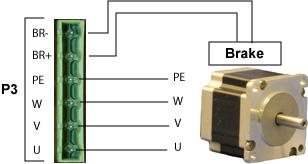
17 P3 Connection for Brushless Servomotors with Brake Ruby is compatible only with 24V brakes. The Engage and the Disengage time may be set in the commissioning software (Motor properties page). Figure 12 P3 Connection to the Brushless Motor with Brake Pin Name Description 6 BR- Brake - 5 BR+ Brake + 4 PE Protective Earth 3 W Motor Phase W 2 V Motor Phase V 1 U Motor Phase U Table 6 Brushless Motor power/brake connector pinout The protective earth (PE) connection ensures that all exposed conductive surfaces are at the same electrical potential as the surface of the Earth. It also ensures that in the case of an insulation fault, a high fault current flows, which will trigger an over current protection device (fuse) that disconnects the power supply. It is required to connect the shield on one side, and leave it opens on the other side. Connecting on both ends could cause a potential difference that may result in current flow in the shield. 8/27/

18 P3 Connection for Brush Servomotors with Brake Ruby is compatible only with 24V brakes. The Engage and the Disengage time may be set in the commissioning software (Motor properties page). Figure 13 P3 Connection to the Brush Motor with Brake Pin Name Description 6 BR- Brake - 5 BR+ Brake + 4 PE Protective Earth 3 NC Not Connected 2 - Motor Motor + Table 7 Brush Motor power/brake connector pinout The protective earth (PE) connection ensures that all exposed conductive surfaces are at the same electrical potential as the surface of the Earth. It also ensures that in the case of an insulation fault, a high fault current flows, which will trigger an over current protection device (fuse) that disconnects the power supply. It is required to connect the shield on one side, and leave it opens on the other side. Connecting on both ends could cause a potential difference that may result in current flow in the shield. 8/27/

19 4.2.5 Encoder Feedback from Servomotor S4 Figure 14 S4 -Encoder I/O Connector Pin Name Description 1 +5V +5V DC Encoder power 2 D_GND Digital Ground 3 A+ Encoder Input A+ 4 A- Encoder Input A- 5 B+ Encoder Input B+ 6 B- Encoder Input B- 7 I+ Encoder Input I+ 8 I- Encoder Input I- 9 HA+ Hall sensor Input A+ 10 HA- Hall sensor Input A- 11 HB+ Hall sensor Input B+ 12 HB- Hall sensor Input B- 13 HC+ Hall sensor Input C+ 14 HC- Hall sensor Input C- 15 TACH Tachometer feedback (with ref to A_GND) 16 A_GND Analog Ground 17 THERM1 Thermistor Input (PTC/NTC/Switch) 18 THERM2 Thermistor Input (PTC/NTC/Switch) 19 ENC_FBK Encoder feedback. See Note 20 +5VDC +5V DC 21 +5VDC +5V DC 22 D_GND Digital Ground 23 D_GND Digital Ground 24 D_GND Digital Ground 25 D_GND Digital Ground 26 D_GND Digital Ground Table 8 Encoder I/O connector pinout Note: Pin 19 must be jumped to digital ground if the encoder is not installed or the ENC_FBK signal is not used to identify an encoder feedback. 8/27/
20 The encoder inputs A and B provide incremental motor position information, and the input is a reference position marker to zero the position. Channels A and B are 90 degrees apart and Channel I is typically a small width pulse that marks the position of the shaft as zero when asserted. The Hall signals are differential inputs, used for speed and coarse position feedback. There are 3 hall inputs - one signal for each motor phase. All signals need to be connected in reference to the Digital ground. The Ruby accepts 5V differential TTL encoder signals. Single-ended or open-collector type hall signals may be used by connecting the positive hall signals to the respective positive hall inputs, and pulling up the negative hall signals to 5V through 475 Ohms resistor. Frequency limit for encoder channels A & B is 15MHz. Note: The mating connector to S4 is DB 26 pins shell size 2 male connector and is provided by the customer. 8/27/
21 4.2.6 I/O Connection S1 Figure 15 S1-Control I/O pins Pin Name Description 1 REF+ + Command Input (ref. to A_Gnd) 2 REF- - Command Input (ref. to A_Gnd) 3 A_GND Analog Ground (for single-ended command input) 4 AO_1 Programmable analog output 1 ( ref to A_Gnd) 5 AO_2 Programmable analog output 2 (ref to A_Gnd) 6 A_GND Analog Ground 7 ENABLE Enable the amplifier (refer to I_Gnd) 8 Limit+ Limit Switch Positive (ref to I_Gnd) 9 Limit- Limit Switch Negative (ref to I_Gnd) 10 DO1/Fault Digital output 1 Amplifier Fault (ref to I_Gnd) 11 DO2/Ready Digital output 2 Ready (ref to I_Gnd) 12 I_GND Isolated Ground 13 I_GND Isolated Ground 14 I_GND Isolated Ground 15 24V 24V DC switch power (ref to I_Gnd) Table 9 Pinout of Control I/O Connector S1 Note: The command voltage input range is +/-10V. Note: The mating connector to S1 is DB 15 pins shell size 2 male connector and is provided by the customer. 8/27/
22 Analog Command Signal The Ruby accepts single or differential command input. Figures below illustrate the input stage. Figure 16 Analog Command Signals The recommended full-scale differential command input range is ± 10V. The offset voltage is the input value at which the output is zero. The deadband is the voltage range for which there is no output response. For example, if the deadband voltage is 100mV, then the drive treats any input up to 100mV as zero, and hence only outputs for input greater than 100mV. Deadband is useful in cases where the rotation due to noise needs to be minimized/eliminated. The offset and the deadband for the input voltage may be set in the commissioning software Analog I/O page. Using Autobalancing (in the Analog I/O page) in the commissioning software sets the offset automatically. The direction of the torque depends on the Velocity/Current command direction in the commissioning software as listed below. Vel/Dir Command Direction 0 1 Command Input Polarity Direction Positive Clockwise Negative Counter Clockwise Positive Counter Clockwise Negative Clockwise Table 10 Torque Direction 8/27/
23 Programmable Analog Outputs Ruby has two programmable analog outputs, which can be selected in the commissioning software. The outputs may be chosen to represent the following motor data: Motor Current Command Current Current Error (Motor current command current) Velocity Feedback Command Velocity Velocity Error (Velocity feedback command velocity) Digital Inputs Illustrates the digital input stage. All the digital inputs are optically isolated. Figure 17 - Digital Input Stage Open Collector, 80 ma max Enable The function of this signal is to enable/disable the drive. The enable signal has to be wired through an external switch. The enable input accepts voltage in the range of VDC. The enable input signal may be configured as active high or active low in the commissioning software Travel Limit Inputs The function of the Limit switches (LS+ and LS-) is to provide an inhibit signal. When either of the inputs is asserted, the motor faults out. When the motor is reenabled, it starts moving in the opposite direction (relative to the direction in which it was moving prior to the fault). These signals maybe configured as active high or active low in the commissioning software. 8/27/
24 Digital Outputs Ruby has two digital outputs Fault and Ready. Both outputs are open collector type and are fully isolated from rest of the circuits. This picture shows the output stage of the digital outputs. Digital output max voltage -- 30V Figure 18 - Digital Outputs Digital Output 1 Fault This output is asserted when there is fault in the system. This may be configured as active high or active low in the commissioning software Digital Output 2 Ready This output is asserted when the system is enabled/ready. This maybe configured as active high or active low in the commissioning software VDC Output The 24 VDC output may be used to power the digital signals Grounding Digital Ground Isolated Ground is used as reference ground for digital I/O Analog Ground Used as reference ground for analog I/O. 8/27/

25 4.2.7 Special Function I/O Connection S3 Figure 19 - S3 Connection Pin Name Function 1 +5V +5 VDC 2 D_GND Digital Ground 3 OUTA+ Encoder output A+ 4 OUTA- Encoder output A- 5 OUTB+ Encoder output B+ 6 OUTB- Encoder output B- 7 OUTC+ Encoder output C+ 8 OUTC- Encoder output C- 9 PULSE+ Pulse input + 10 PULSE- Pulse input - 11 DIR+ Direction + 12 DIR- Direction V +5V DC 14 D_GND Digital Ground 15 D_GND Digital Ground Table 11 - S3 Connection Pinout Note: The mating connector to S3 is DB 15 pins shell size 1 female connector and is provided by the customer. 8/27/
26 Position Mode The pulse input determines the distance moved and the pulse frequency determines the velocity. The direction of torque is determined by the Direction input. These inputs are optically isolated from rest of the circuit. Differential signals are recommended for these inputs since they result in better resolution. Pulse and direction input voltage range 5V Dif. Pulse frequency range - Scaling Direction - + CW and CCW Master/Slave Ruby supports drive slaving from an external pulse input. Desired ratio is selected during commissioning. Connect the Encoder outputs A & B of the master drive to the pulse and direction input of the slave drive. This enables the slave drive to follow the master drive nd Encoder Input In cases where the drive is in position mode and the application requires high position resolution with minimum backlash, a second encoder can be installed on the load side. The encoder is fed into the Ruby for closing the position loop reducing backlash in the system. The pulse and direction inputs may optionally be used as the second encoder input. 8/27/

27 4.2.8 S2 USB Interface to PC The USB connector enables the user to connect the drive to the PC. The windows based program ServoVista is used to configure and tune the drive. Figure 20 - USB Connector Pin Description 1 VBUS 2 D- 3 D+ 4 Not Connected 5 GND Table 12 - USB Pin Description Drive Status LED The LED in Ruby indicates the status of the drive. Here are the lists of the LED status with its respective description. LED Status Solid Orange Solid Green Solid Red Description Drive is powered on, and disabled Drive is enabled Drive is under fault 8/27/
Ser vo Drive Commissioning Instruction
 Ser vo Drive Commissioning Instruction Version 02 www.servodynamics.com Important Notice: This document is object to the following conditions and restrictions: This Document contains proprietary information
BMC-7 CONTROLLER MANUAL
 BMC-7 CONTROLLER MANUAL 1-1-3236-900-00 REV L May 6, 2013 *Please check with the factory for latest version of this controller manual* IMPORTANT PLEASE OBSERVE ALL MOTOR POLYGON ASSEMBLY (MPA) SPECIFICATIONS
PDM16 & PDM32 User Manual
 MoTeC PDM16 & PDM32 User Manual Contents Introduction... 3 Operation... 4 Configuration...4 PDM Manager Software...4 PC Connection...4 Configuration Concepts...4 Conditions...7 Switch Inputs...7 CAN Inputs...8
RT8725. Single-Phase BLDC Fan Driver IC. Features. General Description. Applications
 RT8725 Single-Phase BLDC Fan Driver IC General Description The RT8725 is a single-phase driver IC for fan motors. Rotation speed is controlled by input signal. The RT8725 provides several protection features
INSTALLATION MANUAL AND OPERATING INSTRUCTIONS
 INSTALLATION MANUAL AND OPERATING INSTRUCTIONS MD41-( ) Series GPS ANNUNCIATION CONTROL UNIT FOR NORTHSTAR M3 GPS APPROACH MD41-828 28vdc Horizontal Mount MD41-838 28vdc Vertical Mount (shown on page 13)
MEGATORQUE MOTOR SYSTEM User s Manual
 MEGATORQUE MOTOR SYSTEM User s Manual (ESA23 Driver Unit System) ESA CN4 MOTOR FUSE1 250V 10A FUSE2 250V 10A I/O CN2 RS-232C CN1 POWER DISP. CONT. AC90-220V MAIN AC200-220V T R S VEL. GND SENSOR CN3 FGND
INSTALLATION MANUAL AND OPERATING INSTRUCTIONS
 INSTALLATION MANUAL AND OPERATING INSTRUCTIONS MD41-( ) Series GPS ANNUNCIATION CONTROL UNIT FOR ALLIED SIGNAL KLN 900 MD41-1924 14vdc Horizontal Mount MD41-1934 14vdc Vertical Mount (shown on page 11)
INSTALLATION MANUAL AND OPERATING INSTRUCTIONS
 INSTALLATION MANUAL AND OPERATING INSTRUCTIONS MD41-( ) Series GPS Annunciation Control Unit for Garmin GNS/GTN Systems. MD41-1470 28vdc Horizontal Mount Mid-Continent Instruments and Avionics Manual Number
INSTALLATION MANUAL AND OPERATING INSTRUCTIONS
 INSTALLATION MANUAL AND OPERATING INSTRUCTIONS MD41-( ) Series GPS ANNUNCIATION CONTROL UNIT FOR II MORROW APOLLO 2001TSO / 2001GPS / 2101/ GX50 / GX60 MD41-728 28vdc Horizontal Mount MD41-738 28vdc Vertical
INSTALLATION MANUAL AND OPERATING INSTRUCTIONS
 INSTALLATION MANUAL AND OPERATING INSTRUCTIONS MD41-( ) Series GPS Annunciation Control Unit for Garmin GNS 430/530 VHF Communication and Navigation Management System MD41-1469 28vdc Horizontal Mount MD41-1479
Sensor unit MC2 for toxic gases and oxygen with analog output
 Page 1 July 2016-2 Exchangeable sensor unit including digital value processing, temperature compensation and self control for the continuous monitoring of the ambient air. The sensor unit MC2 houses a
INSTALLATION MANUAL AND OPERATING INSTRUCTIONS
 INSTALLATION MANUAL AND OPERATING INSTRUCTIONS MD41-( ) Series GPS Annunciation Control Unit for GARMIN GPS 400/500, GNC 420 and GNS 430/530 Series Navigation Management System MFG. P/N: MD41-1408A 28VDC
MD Power Supply -48Vdc +Bias Tee
 215988-001MD Power Supply -48Vdc +Bias Tee Operation and Maintenance Manual Mitec Telecom Inc. Designers and manufacturers of telecom and wireless products 9000 Trans Canada, Pointe-Claire, Quebec, Canada
Shur-Shot X-Proof Hydrogen Fluoride Alarm Operations Manual
 Shur-Shot X-Proof Hydrogen Fluoride Alarm Operations Manual P/N 1000006053 Rev E $7%$QDO\WLFV// //& 733 Dairy Rd. Parkton, Md. 21120 www.atbanalytics.com (410) 733-6365 Table of Contents Chapter 1: Getting
Owner's manual SAX-1200D SAZ-1500D SAZ-2500D SAZ-3500D
 Owner's manual SAX-1200D SAZ-1500D SAZ-2500D SAZ-3500D Congratulations on your purchase of a Sundown Audio high performance car audio amplifier. Your new amplifier has been built to the highest standards
Mechatronics Courses by School Period
 Mechatronics Courses by School Period Year One P1 P1 P2 P3 P3 P3 P4 P4 P4 Integrated Systems Industrial Math (Geometry, Trig, Algebra,) Blueprint Reading Machine Tool I (Hand tools-measuring-saws & Drill
Wash Down Duty Non-Contact Sensor
 Wash Down Duty Non-Contact Sensor Instruction Manual Models WDDC1-020/040/060/080/100 WDDC2-020/040/060/080/100 WDDV1-020/040/060/080/100 WDDV2-020/040/060/080/100 Table of Contents 1. General Description.....................................
RT mA, Ultra-Low Noise, Ultra-Fast CMOS LDO Regulator. Features. General Description. Applications. Ordering Information RT9193-
 RT9193 3mA, Ultra-Low Noise, Ultra-Fast CMOS LDO Regulator General Description The RT9193 is designed for portable RF and wireless applications with demanding performance and space requirements. The RT9193
Food & Beverage Portfolio
 Line card Food & Beverage Portfolio Products for the Primary Processes Process Automation DCS A flexible, scalable and innovative control system that ensures the productivity, availability and safety of
Temperature Controllers: JC Series Digital Indicating Controllers. JC Series. High Performance Controllers...at the lowest prices anywhere!
 JC Series High Performance Controllers...at the lowest prices anywhere! Structure Units available in standard DIN sizes (1/16, 1/8, and 1/4 DIN) NEMA 4X protective construction Black enclosure Programmable
Single Pulse Resistance Welder Instruction Pamphlet CD125SP High Accuracy CD Welder
 EN G IN EERI N G Single Pulse Resistance Welder Instruction Pamphlet CD125SP High Accuracy CD Welder Fundamentals of Capacitive Discharge Resistance Welding deliver repeatable welds even during line voltage
Model 5511 & 6611 Scale Controller User s Manual Version 2.66 January Thompson Scale Company WEIGHING SYSTEMS & PACKAGING MACHINERY CONTROLS
 Model 5511 & 6611 Scale Controller User s Manual Version 2.66 January 2016 Thompson Scale Company WEIGHING SYSTEMS & PACKAGING MACHINERY CONTROLS MODEL 5511 SCALE CONTROLLER VERSION 2.66 TOOLS CALIBRATE
Mar11 Rev B
 Product Specification 108-1576 11Mar11 Rev B Patch Panel, Modular Jack To 110Connect Block 1. SCOPE 1.1. Content This specification covers performance, tests and quality requirements for NETCONNECT* Category
The I-7531 CAN Repeater
 The I-7531 CAN Repeater User s Manual Warranty All products manufactured by ICP DAS are under warranty regarding defective materials for a period of one year from the date of delivery to the original purchaser.
Daker DK kva. Parallel installation quick start. Part. LE08927AA-09/15-01 GF
 Daker DK 4.5-10 kva Parallel installation quick start Part. LE08927AA-09/15-01 GF Daker DK 4.5-10 kva UK ENGLISH 3 2 Daker DK 4.5-10 kva Index Introduction 2 1 Important Safety Instructions 2 2 Parallel
Technological Training Programs
 Technological Training Programs On behalf of Noaman Engineering, I would like to introduce you to our training courses. All of our courses cover Theoretical, Practical, and software implementation and
Supplemental Instruction Manual
 PD8 Series ProtEX-MAX Supplemental Instruction Manual Modern, Sleek and Practical Enclosure Display Mountable at 0, 90, 180, & 270 Degrees Explosion-Proof, IP68, NEMA 4X Enclosure PROVU, Trident X2, or
Datenblatt Touch Controller 4/5 Draht Resistiv TC-R4/5-232+USB
 Datenblatt Touch Controller 4/5 Draht Resistiv TC-R4/5-232+USB GMBH CONTENT. Application ------------------------------------------------------------------------------2 2.Function ---------------------------------------------------------------------------------2
SINAMICS S120 Firmware Version V4.8
 SINAMICS S120 Firmware Version V4.8 siemens.com/sinamics Agenda 1 Product family 2 2 Typical applications 4 3 Highlights at a glance 6 4 Overview of customer benefits 8 Page 2 SINAMICS S120 product family
Features. Low Flow Dual Duct VAV/CV with QVM. Application Data Sheet
 Low Flow Dual Duct VAV/CV with QVM Application Data Sheet Figure 1. Dual Duct VAV Box with Two Inlet Flow Figure 2. Dual Duct VAV Box with One Inlet and One Sensors. Discharge Flow Sensor. NOTE: The source
AS950 ALL-WEATHER REFRIGERATED SAMPLER
 AS950 ALL-WEATHER REFRIGERATED SAMPLER Applications Wastewater Collection systems Industrial pretreatment Environmental monitoring Stormwater Sampling has never been this easy. Hach's AS950 sampler controller
Model: LI55 DataView Level Controller Instruction Manual
 Model: LI55 DataView Level Controller www.flowline.com 10500 Humbolt St. Los Alamitos CA 90720 USA Tel (562) 598-3015 Fax (562) 431-8507 Disclaimer The information contained in this document is subject
Taking the LED Pick and Place Challenge
 Taking the LED Pick and Place Challenge Joshua J. Markle Cree, Inc. Joshua_markle@cree.com Abstract For the past few years there has been a shift in the Lighting Industry that has carried over to the surface
FAST POWER FACTOR REGULATOR. Computer-14df - xx - 144a INSTRUCTION MANUAL ( M / 00A ) (c) CIRCUTOR S.A.
 (c) CIRCUTOR S.A.") FAST POWER FACTOR REGULATOR Computer-14df - xx - 144a INSTRUCTION MANUAL ( M 981 611 / 00A ) (c) CIRCUTOR S.A. -------- POWER FACTOR REGULATOR COMPUTER- 14f --------- Page 2 POWER FACTOR REGULATOR COMPUTER-
FAST POWER FACTOR REGULATOR Computer-14df - xx - 144a INSTRUCTION MANUAL ( M 981 611 / 00A ) (c) CIRCUTOR S.A. -------- POWER FACTOR REGULATOR COMPUTER- 14f --------- Page 2 POWER FACTOR REGULATOR COMPUTER-
7700 TEST KIT OPERATIONS MANUAL
 7700 TEST KIT OPERATIONS MANUAL 1 The following specifications apply to the CosaTron Model 7700 Digital Test Kit. SPECIFICATIONS: HV DISPLAY ------------------------------------------- 3 Digit (XX.X KV),
2.8 ( Access Level 3-4)
") BSR-2100 2 4. 2 76 2 1 : ------------------------------------------------------------------------------------------------------------- 7 1.1 ----------------------------------------------------------------------------------------------------------------------
BSR-2100 2 4. 2 76 2 1 : ------------------------------------------------------------------------------------------------------------- 7 1.1 ----------------------------------------------------------------------------------------------------------------------
Power Supply Featuring OMRON s Unique, New Undervoltage Alarm Function with Compact Body Contributing to Machine Downsizing
 Switch Mode Power Supply S8VM (15/30/50/100/150/300/600/1,500-W Models) Power Supply Featuring OMRON s Unique, New Function with Compact Body Contributing to Machine Downsizing New undervoltage alarm function
User Manual. Network Pro Series Tower and Rack-Mount Convertible UPS. Table of Contents 1000/1500/2200/3000
 Table of Contents Network Pro Series Tower and Rack-Mount Convertible UPS User Manual 1 Introduction ------------------------------------------------------------------------------------2 2 IMPORTANT SAFETY
Three-tank System Exercise
 Three-tank System Exercise Advanced Process Control Methods and Process Control Project Work Laboratory of Process Control and Automation 1 Table of Contents 1 Introduction ------------------------------------------------------------------------------
Theft Resistant Shopping Cart Project Proposal
 Theft Resistant Shopping Cart Project Proposal Team 25 Team Members Kong Zhi Yao (kkong7) Mei Ling Yeoh (myeoh2) Zhan (xzhan5) TA: Jacob Bryan ECE 445 Spring 2016 February 10 th, 2016 1 Table of Contents
electroplating DC power supply type SIFCO PROCESS POWER PACK 1028
 Documentation type: Author: Quick start manual J. Schumann Last modification: Last modification by: D. Mayer-Eckardt Print date: 9/9/2010 10:46 AM Last saving: 9/9/2010 10:46 AM Doc-Nr.: ZK-xxxxxx-01-V01
SELECTION GUIDE Appearance Sensing distance Operation Mode Connector Shape example (M8) Outer diameter (Ferrous material only) Wiring Output Output no
 Outer diameter (Ferrous material only) Wiring Output Output no") Stainless Steel Sensing Face Proximity Switch Model FL7S The FL7S is a proximity switch having a stainless steel sensing face and housing, and is specially designed for welding applications on the automobile
Stainless Steel Sensing Face Proximity Switch Model FL7S The FL7S is a proximity switch having a stainless steel sensing face and housing, and is specially designed for welding applications on the automobile
Technical System Catalogue Modular PDU (PSM)
") Technical System Catalogue Modular PDU (PSM) Benefits of PSM busbars at a glance Modular configuration, flexibly extendible Redundant designs in busbars are supported Vertical mounting in the rack without
Technical System Catalogue Modular PDU (PSM) Benefits of PSM busbars at a glance Modular configuration, flexibly extendible Redundant designs in busbars are supported Vertical mounting in the rack without
Table of Contents. Installation 2-10 Leveler legs... 2 Controller... 4 Dip-switch Configurations. 5 Wire Harness Installation.. 7
 Table of Contents Installation 2-10 Leveler legs... 2 Controller... 4 Dip-switch Configurations. 5 Wire Harness Installation.. 7 Operation 11-14 Program HOME Position... 12 Program/Reprogram AUTO Level
July P Wide Format Stacker User Guide
 July 2009 701P49768 Wide Format Stacker User Guide 2009 Xerox Corporation. All rights reserved. Xerox and the sphere of connectivity design are trademarks of Xerox Corporation in the United States and/or
TR1 TR2. Transformer / Relay Adapter. Installation Manual. Rev 1.1 Feb. 22, Deklin Technologies Inc 413 Childe Harolds Lane Brentwood, TN 37027
 TR1 TR2 Transformer / Relay Adapter Installation Manual Rev 1.1 Feb. 22, 2016 Deklin Technologies Inc 413 Childe Harolds Lane Brentwood, TN 37027 Tel: (615) 819-0800 Fax: (615) 819-0801 www.deklintech.com
Industrial Solutions. Quality is Our Driving Force. interfaceforce.com
 Industrial Solutions Quality is Our Driving Force interfaceforce.com The high performance you ve come to know and trust from Interface products is also available in a rugged industrial configuration. Since
Standard of Practice - Campus Electrical Distribution System
 A26.3 Standard of Practice - Campus Electrical Distribution System NOTE: Significant revisions or additions to the previous standards are highlighted in italics. GENERAL Designers shall verify that all
SOLAR WATER PUMP KIT MODEL: SIS-10HP
 SOLAR WATER PUMP KIT MODEL: SIS-10HP Model: SIS -10HP Pump Size: 6 Capacity in HP: 10 PV Size in kw: 10 Water head range 14-53 meter Water quantity range 20000-78000 liter per hour Quantity Description
Bonded Neo Magnetization Guide
 Bonded Neo Magnetization Guide 1 Presentation Outline 1. Magnetizing Systems 2. Fixture Design 3. Construction 4. Testing 5. Design Study 2 Magnetizing Systems A typical magnetizing system consists of
SIWAREX FTC-B Weighing Module for Belt Scales Set-up of SIWAREX FTC with SIWATOOL FTC_B
 SIWAREX FTC-B Weighing Module for Belt Scales Set-up of SIWAREX FTC with SIWATOOL FTC_B Quick Guide For modules with order number 7MH4900-3AA01 1 Hardware Requirements... 3 2 Connections... 5 3 SIWATOOL
Title: YALE OFFICE OF FACILITIES PROCEDURE MANUAL Chapter: 01 - Yale Design Standard Division: Electrical Standards
 Date Description of Change Pages / Sections Modified ID 6/15/16 Updated format, division title, and removed references to other sections. - mgl44 A. Summary This section contains design criteria for the
ALLIED ELECTRONICS, INC STATION SITE CONTROLLER (SSC) Installation and Start Up Guide. ARCO / ANDI to Wayne PIB
 Installation and Start Up Guide. ARCO / ANDI to Wayne PIB") ALLIED ELECTRONICS, INC STATION SITE CONTROLLER (SSC) Installation and Start Up Guide ARCO / ANDI to Wayne PIB ALLIED ELECTRONICS, INC 2210 FARRAGUT AVENUE BRISTOL, PA 19007-0624 PHONE: 215.785.6200 FAX:
ALLIED ELECTRONICS, INC STATION SITE CONTROLLER (SSC) Installation and Start Up Guide ARCO / ANDI to Wayne PIB ALLIED ELECTRONICS, INC 2210 FARRAGUT AVENUE BRISTOL, PA 19007-0624 PHONE: 215.785.6200 FAX:
MNL, SEL DIMENSIONS, SITE AW PLANNING GUIDE ARTWORK SIZE A SHEET 1 OF 1
 Artwork and Signature File for: MAN-01120, MNL, SEL DIMENSIONS, SITE PLANNING GUIDE Artwork consists of: Thirty-Six (36) 8 ½ inch x 11 inch sheet(s) attached. REV AUTHORED BY DATE A.TAMBASCIO 01/20/10
Scanning Devices Label Counting Table Operations Manual
 Scanning Devices Label Counting Table Operations Manual This document describes the functions performed by counting table components and suggests procedures for setting up and operating the counting table.
Digital Self Contained Weighing Module
 Model 9010D Digital Self Contained Weighing Module FEATURES Capacities 3-90kg Unique adjustable tare load cancelling mechanism Highly effective viscous damping 6 Built-in overload limit stops in three
15 Pin DSUB - MALE 15 Pin DSUB - FEMALE 9 Pin DSUB - MALE 9 Pin DSUB - FEMALE
 Last Revised: 6 Oct 07 Description: This data sheet show our range of high quality appliance cables, such as signal cables (VGA / DVI / DisplayPort (DP)), Touchscreen and power cables. These are either
Oxygen Sensor QGO20...
 QGO20.000D17 QGO20.000D27 Oxygen Sensor QGO20... Basic Documentation The QGO20 and this Basic Documentation are intended for use by OEMs which integrate the oxygen sensor in their products! CC1P7842en
2000 User/ Installer Guide
 MODELS SH 16, 30, 50, 75, 100 Now Up To 14 Digit Dialing 2000 User/ Installer Guide Select Entry Systems This page intentionally blank. TABLE OF CONTENTS 1.0 INTRODUCTION... 1 1.1 ENVIRONMENTAL... 1 1.2
Melt tension measurement (Haul-Off)
") Göttfert Werkstoff-Prüfmaschinen GmbH Siemensstraße 2 74722 Buchen Email: info@goettfert.de Internet: http://www.goettfert.com WERKSTOFF-PRÜFMASCHINEN GMBH Melt tension measurement (Haul-Off) The Haul-Off
Göttfert Werkstoff-Prüfmaschinen GmbH Siemensstraße 2 74722 Buchen Email: info@goettfert.de Internet: http://www.goettfert.com WERKSTOFF-PRÜFMASCHINEN GMBH Melt tension measurement (Haul-Off) The Haul-Off
PD662 Loop-Powered Meter Instruction Manual
 PD662 Loop-Powered Meter C US 4-20 ma Input Loop-Powered -1999 to 2999 Display Easy Four-Button Programming NEMA 4X Enclosure Loop-Powered Backlight Option 1.7 Volt Drop without Backlight 32-Point and
product specifications e
 Wallbox The Wallbox controls up to six zones of light and will operate the following sources with a continuous Square Law dimming curve or on a full conduction non-dim basis: Incandescent LED, Tungsten
Equipment Requirements SBC Local Exchange Carriers May 2001 NETWORK EQUIPMENT POWER, GROUNDING, ENVIRONMENTAL, AND PHYSICAL DESIGN REQUIREMENTS
 TP76200MP NETWORK EQUIPMENT POWER, GROUNDING, ENVIRONMENTAL, AND PHYSICAL DESIGN REQUIREMENTS Contents Page Contents Page 1. GENERAL... 1 A. Purpose... 1 B. Definitions... 1 C. Product Evaluation Process...
DIGITAL NITROUS PROCESSOR Installation and Instruction Manual
 DIGITAL NITROUS PROCESSOR Installation and Instruction Manual For Accel DFI part number: 74186 VER 3.1 INSTR74186 Table of Contents Introduction...3 Handheld Programmer Quick Menu Flow Chart...4 Programing
RapID Raw Materials Verification System
 RapID Raw Materials Verification System Pre-Installation Guide NOTICE: This document contains references to Cobalt or Cobalt Light Systems. Please note that Cobalt Light Systems was purchased by Agilent
Y-HEAT THERMAL MANAGEMENT SYSTEM FOR OVEN, FURNACE, VACUUM FURNACE, AND CRYOGENIC CHAMBER SYSTEMS. Product Overview and Specifications
 Y-HEAT THERMAL MANAGEMENT SYSTEM FOR OVEN, FURNACE, VACUUM FURNACE, AND CRYOGENIC CHAMBER SYSTEMS Product Overview and Specifications Y-HEAT Overview Throughout the thermal industry, ovens, furnaces, vacuum
AVPTC. Multi-Position, Variable-Speed, ECM-Based Air Handler with Internal TXV ComfortNet Compatible 1½ to 5 Tons. Contents.
 Multi-Position, Variable-Speed, ECM-Based Air Handler with Internal TXV ComfortNet Compatible 1½ to 5 Tons Contents Air Handler Nomenclature... 2 Heater Kit Nomenclature... 2 Product Specifications...
ARC STUD WELDING SYSTEMS
 ARC STUD WELDING SYSTEMS ARE complete stud welding systems which weld ARC studs using the ARC stud welding process. CONSIST OF the following items: An ARC stud welding power supply with built-in timer/control
PERFORMANCE OF VAISALA OZONE INTERFACE BOARD OIF411
 PERFORMANCE OF VAISALA OZONE INTERFACE BOARD OIF411 White Paper B211385EN-A Performance of Vaisala Ozone Interface Board OIF411 This page intentionally left blank. 2 B211385EN-A Table of Contents CHAPTER
MERIGAUGE MODEL 3900 OPERATING INSTRUCTIONS
 99 Washington Street Melrose, MA 02176 Phone 781-665-1400 Toll Free 1-800-517-8431 Visit us at www.testequipmentdepot.com MERIGAUGE MODEL 3900 OPERATING INSTRUCTIONS Meriam Instrument s MERIGAUGE Model
LD2985. Very low drop and low noise voltage regulator with inhibit function. Features. Description
 ery low drop and low noise voltage regulator with inhibit function Datasheet - production data to 30 µrms. Typical application are in cellular phone, palmtop laptop computer, personal digital assistant
Pallet Safe: Installation Supplement Rev
 Pallet Safe: Installation Supplement Rev. 4-1-13 Smartscan Incorporated, 33083 Eight Mile Road, Livonia MI 48152 Tel: (248)477-2900 Fax: (248) 477-7453 Web: www.smartscaninc.com SMARTSCAN INCORPORATED
ELVORON LU/LA ELEVATOR
 Creating An Accessible World ELVORON LU/LA ELEVATOR DESIGN AND PLANNING GUIDE www.garaventalift.com Please note: Dimensions provided in this Guide are for REFERENCE ONLY and should not be used for site
Revision 1 RAM ELEVATORS. Elevator Electrical Planning Guide. RAM Manufacturing Ltd
 RAM ELEVATORS Elevator Electrical Planning Guide This guide is intended for people with an understanding of electricity. If you are not, please consult a licensed electrician as errors in application of
Electrical Networks Principles and Performance
 Engineering Standard Electrical Networks Electrical Networks Principles and Performance Version: 1 Issued: January 2015 Owner: Chief Engineer Approved By: Paul O Halloran Chief Engineer PRINTOUT MAY NOT
Three-sided barrier compliant to DIN EN ISO Depending on location, design also as wind protection. Clear height (DH) Three-sided barrier
 Three-sided barrier") of 5 Page Car SingleVario 06 Stack Parker 06 50 for vehicle up to 5.00 m = 6 long (50 for vehicle up to 5.0 m 7 long) Depending on location, design also as wind protection. Product Data CONFORMITY 06/06/G63
of 5 Page Car SingleVario 06 Stack Parker 06 50 for vehicle up to 5.00 m = 6 long (50 for vehicle up to 5.0 m 7 long) Depending on location, design also as wind protection. Product Data CONFORMITY 06/06/G63
Customer Interface Publication: KCOM (Hull) CIP003
 CIP003") Customer Interface Publication: KCOM (Hull) CIP003 Public Switched Telephone Network (PSTN) Technical Characteristics of the Direct Dialling Inward Exchange Line Interface Issue: 1.2 April 2016 The information
Customer Interface Publication: KCOM (Hull) CIP003 Public Switched Telephone Network (PSTN) Technical Characteristics of the Direct Dialling Inward Exchange Line Interface Issue: 1.2 April 2016 The information
Quick Guide. CSN950 MultiHead Dimensioner _v2d_MAN_QG_CSN950MH_EN
 Quick Guide CSN950 MultiHead Dimensioner File: 20160406_v2d_MAN_QG_CSN950MH_EN CSN950 MultiHead Quick Guide Table of Contents 1. Safety Instructions... 2 Safety and General Precautions... 2 2. Specifications
TF20 Tray Feeder. Instruction Manual. for JEDEC and IEC Standard Trays
 for JEDEC and IEC Standard Trays Instruction Manual 096-0243-003 Data I/O assumes no liability for errors, or for any incidental, consequential, indirect, or special damages, including, without limitation,
MPK 411 CONTROL SYSTEM
 CONTROL SYSTEM OPERATING INSTRUCTION Kollmorgen Steuerungstechnik GmbH Broichstraße 32 51109 Köln Phone +49 (0) 221 89 85 0 Fax +49 (0) 221 89 85 30 http://www.kollmorgen.de Email: info@kollmorgen.de KOLLMORGEN
x act i Precision Pressure Transmitter for Food Industry, Pharmacy and Biotechnology Stainless Steel Sensor accuracy according to IEC 60770: 0.
 Precision Pressure Transmitter for Food ndustry, Pharmacy and Biotechnology Stainless Steel Sensor accuracy according to EC 60770: 0. % FSO Nominal pressure from 0... 400 mbar up to 0... 40 bar Output
3 PHASE ENERGY ELECTRONIC METERS MKB-363-M INSTRUCTION MANUAL ( M / 00 B
 3 PHASE ENERGY ELECTRONIC METERS MKB-363-M INSTRUCTION MANUAL ( M 981 198 / 00 B ) (c) CIRCUTOR S.A. -- MKB-363-M ELECTRONIC METERS -- M-981198 -- Page Nº 2 THREE-PHASE THREE-WIRE ACTIVE ENERGY ELECTRONIC
kva single and parallel UPS Systems User s and Installation Manual
 80-130 kva single and parallel UPS Systems User s and Installation Manual 80-130 kva single and parallel UPS Systems CONTENTS 1. Introduction... 5 2. System description... 5 2.1 General description...
Data Bus Connector and Terminator Requirements Document DB-1001-A. Revision C
 Data Bus Connector and Terminator Requirements Document DB-1001-A Revision C 2507 W. Geneva Dr. Tempe, Arizona 85282 Phone [602] 231-8616 FAX [602] 273-9135 www.phxlogistics.com TABLE OF CONTENTS 1. Introduction
ENGLISH Datasheet JIS Miniature Thermocouple Connector PCB Mounting Socket Types K, J, T, E, R/S & B (JIS Colour Code)
") ENGLISH Datasheet JIS Miniature Thermocouple Connector PCB Mounting Socket Types K, J, T, E, R/S & B (JIS Colour Code) Versatile, high quality, circuit board mounting miniature socket Specially designed
ENGLISH Datasheet JIS Miniature Thermocouple Connector PCB Mounting Socket Types K, J, T, E, R/S & B (JIS Colour Code) Versatile, high quality, circuit board mounting miniature socket Specially designed
ACT. Summary. 1 Introduction. 2 Synoptic. 3 Technical characteristics. 4 Part-numbering system. 5 Arrangements. 6 Receptacles. 7 Plug / Panel seal
 Summary 1 Introduction 2 Synoptic 3 Technical characteristics 4 Part-numbering system 5 Arrangements 6 Receptacles 7 Plug / Panel seal 8 Mating and unmating dimensions 9 Mounting cutouts 10-11 Contacts
DVPTC. Multi-Position, Variable-Speed, ECM-Based Air Handler with Internal TXV ComfortNet Compatible 2 to 5 Tons
 DVPTC Multi-Position, Variable-Speed, ECM-Based Air Handler with Internal TXV ComfortNet Compatible 2 to 5 Tons Contents Air Handler Nomenclature...2 Heater Kit Nomenclature...2 Product Specifications...3
WP200e Wallbox to CD Changer Adapter
 WP200e Wallbox to CD Changer Adapter Supported Wallbox Models AMI W-40 & W-80 & W-120, 40/80/120 Select AMI WQ-200, 200 Select Rock-Ola 1558 & 500, 160 Select Rock-ola 1555, 200 Select Rowe WRA, WRB &
Welding Force Calibration Transmitter
 Force Welding Force Calibration Transmitter System for Measuring the Electrode Force in Spot Welding Type 9831C... Measuring system for testing and calibrating the electrode force in spot welding machines
alpha single screw extruders
 alpha single screw extruders Index Extruder models Applications Basic and optional equipment Technical data Processing unit Screw designs / output list SecuRe functionality Interfaces and synchronization
SM-220-MP SHOCK TEST MACHINE. Halfsine. Sawtooth. Squarewave
 SHOCK TEST MACHINE SM-220-MP Halfsine Sawtooth Squarewave Technical subject to changes without prior notice! GUTENBERGSTRASSE 27 D-246 REINBEK / HAMBURG GERMANY SM-220-MP SHOCK TEST MACHINE Dimensions
FAST SPOTTER WT-FS-5.0
 . FAST SPOTTER WT-FS-5.0 Installation, Operating and Maintenance Manual WELDING TECHNOLOGIES www.weldingnet.com 1365 Horseshoe Dr., Blue Bell, PA 19422 Phone: 610-278-9325 Fax: 610-278-9325 Toll Free Number:
IPC-SMEMA Mechanical Equipment Interface Standard IPC-SMEMA Supersedes SMEMA 1.2 ASSOCIATION CONNECTING ELECTRONICS INDUSTRIES
 ASSOCIATION CONNECTING ELECTRONICS INDUSTRIES IPC-SMEMA-981 Mechanical Equipment Interface Standard IPC-SMEMA-981 February 200 Supersedes SMEMA 1.2 A standard developed by IPC 3000 Lakeside Drive, Suite
Design Qualification Test Report SMS/TMS SMS L-D/TMS L-D
 Project Number: Design Qualification Test Report Tracking Code: 147211_Report_Rev_1 Requested by: Joe Smallwood Date: 11/11/2011 Product Rev: 0 Lot #: N/A Tech: Peter Chen Eng: Vico Zhao Qty to test: 45
Multi-Purpose Mechanized Welding Carriage
 WEL-HANDY MULTI Multi-Purpose Mechanized Welding Carriage Feature & Benefits Two Models Available Standard and Programmable Stitch/Tack Multi Weld Process Standard and Programmable Stitch/Tack Multiple
DESIGN VERIFICATION TEST REPORT ERCDA SS-TD-TU. Mated with ERF L-DV-L
 Project Number: Tracking Code: TC0810--1621 Requested by: John Riley Date: 05/27/2008 Product Rev: 0 Part #: ERCDA-25-09.00-1SS-TD-TU Lot #: N/A Tech: Eric Fox & Daniel Borgelt Eng: Troy Cook Qty to test:
nicrom e l e c t r o n i c
 G E N E R A L High Performance Thick Film Resistors C A T A L O G 3 Nicrom Electronic Via Roncaglia CH - 6883 Novazzano SWITZERLAND Phone : ++4 () 9 68 99 86 Fax : ++4 () 9 68 99 86 info@nicrom-electronic.com
Powerware 9120 UPS. Date: Issued By: Product Affected May 27, 2003 Gary Bankay PowerFlex 7000 MV Drive
 Medium Voltage Support Technical Services Update Title: Powerware 90 UPS Product Update Number: PF000_GEN- Date: Issued By: Product Affected May, 0 Gary Bankay PowerFlex 000 MV Drive Only personnel who
Model PM-616 Two-Color Pyrometer Operator s Manual Revision 1.2
 Model PM-616 Two-Color Pyrometer Operator s Manual Revision 1.2 Logika Technologies Inc. 2857 Sherwood Heights Dr. Unit 2 Oakville ON, CanadaL6J 7J9 Tel: 905-829-5841 www.logikatech.com Logika Technologies