CHAPTER V. Microporous Membranes of Polyoxymethylene from a Melt-Extrusion Process: (I) Effects of Resin Variables and Extrusion Conditions
|
|
|
- Rudolf Whitehead
- 6 years ago
- Views:
Transcription
1 172 CHAPTER V Microporous Membranes of Polyoxymethylene from a Melt-Extrusion Process: (I) Effects of Resin Variables and Extrusion Conditions ABSTRACT A two part study utilizing polyoxymethylene (POM) was undertaken to investigate a three stage process (Melt-Extrusion/Annealing/Uniaxial-Stretching) (MEAUS) employed to produce microporous films. In this first part, three POM resins (D, E & F) were melt-extruded into tubular films (blowup ratio; BUR = 1), where resin D has a higher weight average molecular weight (M w ) than resin E but both possess similar relatively narrow molecular weight distributions (MWD). In contrast, resin F is characterized by a broader MWD while its M w is slightly lower than resin D. Specific attention was focused upon the morpholog ical and crystal orientation results as a function MWD and M w. A stacked lamellar morphology was obtained in each case from the melt-extrusion, however, the type of stacked lamellar morphology, planar or twisted, and the orientation state was found to depend upon both the resin characteristics and the melt-extrusion conditions. Atomic force microscopy and wide-angle X-ray scattering were the main techniques utilized to study the melt-extruded films while dynamic melt rheometry in conjunction with the Carreau-Yasuda model aided in differentiating the melt-flow behavior of the three resins. Small-angle light scattering (SALS) was also employed to characterize the morphological state.
2 INTRODUCTION In a previous investigation 1 by the authors, isotactic poly(4-methyl-1-pentene) (PMP) was studied in a sequential manner from resin to final film with respect to the three-stage (meltextrusion/annealing/uniaxial-stretching) (MEAUS) method utilized to produce a microporous membrane. From this study, the authors verified a number of prerequisites for microporous membrane formation via the method in question. The first prerequisite is the ability of the oriented polymer to crystallize at a sufficient rate so that main chain melt relaxation does not occur during extrusion. Fast crystallization kinetics then enable a tubular film (blowup ratio; BUR = 1) to be produced with a planar stacked lamellar morphology (little or no lamellar twisting) and high crystalline orientation. Also, it is undesirable to have a h igh concentration of long fibril nuclei similar to the structures reported by Yu and coworkers 2 for linear high density polyethylene (HDPE) tubular films, which were found to pin the lamellae together during uniaxial-stretching (third stage). A rapid quenching process and control of the film thickness to approximately 1 mil (25 µm), which then minimizes any skin-core effects, also facilitate a uniform parallel planar texture and high crystalline orientation throughout the film cross-section. The last prerequisite proposed by the authors is the ability of the polymer chains to translate through the crystal phase at a temperature below the T m. This thermally activated transition is conventionally referred to as the α c relaxation, and greater detail regarding its origin is presented elsewhere,3,4. The PMP α c relaxation was suggested to be required if a microporous membrane was to be obtained by the MEAUS process. Further evidence for this supposition exists for both HDPE 4 and isotactic polypropylene (ipp) 4 are known to possess an α c relaxation and microporous films of each are commercially available via the MEAUS process 5. Since this hypothesis has been verified for a three polyolefin materials (HDPE, ipp, PMP), it is of interest to test the α c supposition utilizing a non-polyolefin highly crystalline polymer. A semicrystalline polymer known to possess an α c relaxation that is not a polyolefin is polyoxymethylene (POM). While this polymer has been shown to be capable of forming a microporous structure 6,7, it has not been investigated specifically with this in mind. Instead it was studied for its ability to display hard-elastic character when processed using the proper melt conditions. Additionally, there has not been a sequential study of POM from resin to final film with respect to the MEAUS method. Besides hoping to verify the proposed criteria for a non-polyolefin, if produced into a final film possessing highly interconnected micropores, a
3 174 POM membrane could serve in applications requiring a somewhat more hydrophilic film then the polyolefin membranes currently available. For example, HDPE and ipp membranes are utilized in microfiltration applications as well as battery separators between the cathode and the anode in an electrolyte solution 8. The sequential investigation of POM from resin to final film utilizing the MEAUS method will be undertaken in the course of two papers. This first paper addresses the melt-extrusion stage where the results of a number of melt-extrusion conditions applied to three different POM resins will be presented. The effect the extrusion conditions and the resin characteristics have on the resulting precursor film morphology and crystal orientation will be analyzed. The main goal is to produce a precursor with a high crystal orientation and a stacked lamellar morphology where the lamellae are characterized as planar and which facilitate micropore formation via lamellar splaying (separation) during the uniaxialstretching stage that will be addressed in part II 9 of this work. The precursor properties of interest are the crystalline orientation, the morphology, the level of crystallinity, the melting point of the crystalline phase, and the α c relaxation. The first was followed via wide-angle X-ray scattering (WAXS) and quantitatively evaluated using Hermans orientation function (f H ). The morphology of the extruded film has been studied with the aid of atomic force microscopy (AFM). Small-angle light scattering (SALS) also has, in some instances, been employed to observe structures on the order of the wavelength of light. For example, H v SALS (horizontal polarizer and vertical analyzer) of an undeformed optically anisotropic spherulitic morphology typically yields a symmetric four lobed pattern termed the cloverleaf pattern that possesses four-fold symmetry. 10 Such unoriented optically anisotropic spherulitic superstructures are not normal for flow induced morphologies but have been observed in the case of linear low density PE blown (BUR > 1) and cast roll films where near four-fold symmetry of the H v SALS patterns were found in some instances. 11 For isotactic poly(1-butene) (PB-1) tubular extruded films, studied by Hashimoto and coworkers 12, butterfly-type H V SALS patterns occurred, which stemmed from isolated sheaf-like structures. Thus, the SALS technique has been previously employed for investigating tubular or blown film and was utilized here for the POM precursors to observe if there are anisotropic superstructures on the scale of the wavelength of light. Small-angle X-ray scattering (SAXS) was employed to estimate the long spacing of the stacked lamellae that compose the precursors while differential scanning calorimetry (DSC) was used to assist in determining the melting point and level of crystallinity.
4 175 Considerable effort has been devoted to studying the crystalline structure and orientation state of extruded semicrystalline films by a variety of techniques including those previously listed. The row nucleated lamellae model as a result of fibril nucleation proposed by Keller and Machin 13 is accepted in many studies as a common feature of melt-extruded films or more generally for crystallization under extrusion stress. The level of this stress has also been shown to influence the final film properties. A low stress condition results in widely spaced fibril nuclei that are aligned along the principal flow direction, i.e., the machine direction (MD). Lamellae nucleate from the fibrillar structures often become twisted ribbon-like structures as a result of the wide spacing between fibril nuclei. It is, however, questionable whether lamellar twisting occurs for all semicrystalline polymers, and if lamellar twisting may also be a function of the molecular weight distribution (MWD). Thus, this morphology may not be present in all materials extruded under low stress conditions. Crystallization under high stress also produces highly aligned fibril nuclei, however, these structures are more concentrated which then produces a more parallel planar (non-twisted) lamellar morphology. Regarding polyethylene (PE), the latter extrusion stress case results in a c -axis orientation diffraction pattern while the low stress case produces signs of a -axis orientation caused by the twisted or tilted lamellae. Based upon the suggested criteria for the formation of a highly interconnected microporous structure, the latter or high stress extrusion condition produces the desired outcome. The stress applied to the melt is actually a consequence of the melt-extrusion variables such as extrusion temperature, extrusion rate, quench height, and line speed (or uptake). The molecular characteristics of the resin, e.g. weight average molecular weight (M w ) and MWD, also are known to play critical roles on the precursor properties. 1,2,14-18 For both meltextrusion conditions and resin characteristics, it is the effect either variable has on the orientation state of the molecular conformations of the melt, specifically the degree of chain extension prior to crystallization, that is a crucial factor influencing the morphology and crystalline orientation. 15 Thus, the melt-extruded film morphology and orientation provide a window into the melt-flow behavior prior to crystallization while the degree of chain extension in the melt influences the precursor properties. In this work, the authors will present a number of stacked lamellar morphologies observed in POM extruded tubular films. The formation of these morphologies will be shown to depend mainly upon the resin characteristics and are therefore a consequence of the melt flow/relaxation behavior of the resin during crystallization
5 176 at the air ring. A number of these precursors will then be selected based upon their morphologies and crystalline orientations for thermal annealing followed by uniaxial stretching along MD, i.e., the second and third stages, respectively, of the MEAUS process. In these subsequent stages, a number of variable combinations will be explored for their influence on structure and orientation with the overall goal of producing a highly uniform microporosity throughout the final film. The results from the second and third stages, however, will be presented and discussed within a later report EXPERIMENTAL Materials Two POM resins designated as resins D and F were mainly employed in this study, however a third resin labeled E was also investigated albeit to a lesser extent. Two of the three commercial resins (D and E) are a result of the same anionic polymerization of formaldehyde and end-capping the chains using acetic anhydride. The acetic anhydride is employed to stabilize the chain because POM has a relatively low ceiling temperature (ca 120 C) and the chain undergoes depolymerization (unzipping) initiated at the hydroxyl end groups without end-capping. Resins D and E resins differ in M w and M n but both possess a MWD of approximately 2. The third resin, F, is polymerized via a ring-opening polymerization mechanism. This particular synthesis utilizes a small amount of the comonomer ethylene oxide to provide thermal stability to the POM chain. 19 Additionally, and of significance to this study, resin F is characterized by a distinctly broader MWD (ca 5.9) than either resins D or E. More information addressing the three resins will be provided in the results section. Melt Rheological Characterization The three resin samples were compression molded at 180 C for a total time of ten minutes. The samples were allowed to melt at atmospheric conditions for four minutes and then subjected to a low molding pressure for an additional six minutes. The molded samples were subsequently quenched under ambient conditions upon removal from the press. The 25.4 mm diameter compression molded disks were of 2 mm in thickness. The modulus of the complex viscosity ( η* ) as a function of frequency (ω) in radians/sec was obtained by a RMS Rheometrics 800 Spectrometer using a parallel-plate geometry. The rheometer test chamber was operated with a nitrogen atmosphere to minimize polymer degradation. The rheometer
6 177 was preheated to the testing temperature of 180 C and allowed to reach thermal equilibration before loading of the specimens. The samples were squeezed between the plates to a thickness of 1.5 mm; at this time the excess sample was trimmed. From sample insertion and trimming to initiating the frequency sweep, a total time of 10 minutes elapsed. The η* versus ω data were curve fitted using the modified three parameter Carreau- Yasuda (CY) model, Eqn. 5.1, to obtain the CY parameters: η 0, the zero shear viscosity, a the parameter which describes severity or sharpness of the transition from Newtonian to shear thinning behavior, and τ n the characteristic melt-relaxation time which is correlated to the frequency where shear-thinning begins. The power law number (n), when set equal to 2/11, provided accurate CY fits to the POM rheological data and thus was held constant to lower the number of fitting parameters. Further details regarding the CY model may be found elsewhere η * ( ω) = η [ ( ) ] ( 1 n) a 1+ ωτ a Another parameter that has been used 11 to aid in understanding the melt-flow behavior is the recoverable shear strain parameter (RSP or γ ), which is a measure of the melt elasticity. The RSP can be described mathematically in the limit of zero shear rate as shown in Eqn 5.2. γ n o N 1 = 2τ The parameter N 1 is the first normal stress difference and τ is the shear stress, which is equal to ( ω) ω * η in the limit of zero shear rate. If the empirical Cox-Merz 24 rule, η γ& )= η* ω ( ), is applied, the frequency dependent viscosity can be related to the ( ( ) ω= γ& shear-rate dependent viscosity. It can also be shown that the first normal stress can be approximated by the elastic component of the complex shear modulus (G ) in the limit of ω approaching zero; 25 mathematically this becomes: lim ω 0 N 1 = 2 G Therefore using the above allows Eqn. 5.2 to be rewritten at low frequencies as, RSP = γ ~ G ω η * ( ω) (Eqn. 5.1) (Eqn. 5.2) (Eqn. 5.3) (Eqn. 5.4)
7 178 It is Eqn. 5.4 that will be utilized to estimate the elasticity of the melt at low frequency (< 0.05 radian/sec) and provide a basis for better understanding and differentiating the melt-flow behavior of these resins. Tubular Film Processing All the tubular film (1:1 blow up ratio) samples were of one mil (25µm) thickness and all were made on a laboratory scale blown film line. This film line was comprised of a MPM brand extruder using an annular die with a diameter of 3 inches (76 mm), a die gap of inches (1.8 mm), a single screw with a 1.5 inch (37.5 mm) diameter (aspect ratio, L/D=36). Films were quenched with a single lip Western air ring system using ambient air ca. 25 C. A schematic of the tubular film extruder is shown in Fig. 5.1 with the important features labeled with the extrusion conditions utilized. Four main processing parameters: melt extrusion temperature, T melt, extrusion speed of the screw in revolutions per minute (rpm), quench height, which is the distance from the die exit to the cooling ring, and the line speed in meters per minute (mpm) are listed with the specific conditions utilized in Tables for the resins D, E, and F, respectively. In the case of resin E, three extrusion conditions were utilized and these matched three of the conditions for resin D and one condition for resin F. The extrusion setup promotes planar extensional flow with the deformation direction along the MD. This leads to expected uniaxial symmetry about the MD axis, 1,2 as will be verified later by WAXS and refractometry. Table 5.1 Summary of melt-extrusion conditions for Resin D. Extrusion Melt Temperature Extrusion Speed Quench Height Line Speed Sample Condition ( C) (rpm) (cm) (mpm) D D D D D D Table 5.2 Summary of melt-extrusion conditions for Resin E.
8 179 Extrusion Melt Temperature Extrusion Speed Quench Height Line Speed Sample Condition ( C) (rpm) (cm) (mpm) E E E Table 5.3 Summary of melt-extrusion conditions for Resin F. Extrusion Melt Temperature Extrusion Speed Quench Height Line Speed Sample Condition ( C) (rpm) (cm) (mpm) F F F F F In all cases, the line speed was adjusted to maintain a nominal film thickness of 1 mil (25 microns). Further, the flow rate of the air through the air ring was kept constant in this study where in a previous publication 2 from this laboratory that addressed HDPE, this variable was investigated utilizing a similar extrusion scheme.
9 180 Collapsing guides & Nip rolls Line speed (14 & 19 m/min) Tubular film Cooling ring Quench height (2 & 5 cm) Extruder (20 & 45 rev/min) Die (0.18cm) Melt-Extrusion Temperature (170, 180, 185, 195 C) Figure 5.1 Schematic depicting the tubular extrusion setup utilized in this study with some processing parameters indicated.
10 181 Structural and Optical Techniques and Analysis Utilized Wide-Angle X-ray Scattering (WAXS) WAXS studies were performed on a Philips table-top x-ray generator model PW1720 equipped with a standard vacuum sealed Warhus photographic pinhole camera. The X-ray beam was of Cu Kα radiation, λ = Å, and was collimated to a beam diameter of inches (0.508 mm). As will be shown later, the planar extensional flow along the MD promoted uniaxial orientation behavior along this same axis. A commonly reported parameter for uniaxially oriented systems is a second moment average, termed the Hermans orientation, and is expressed by Eqn ( 2 3 cos θ 1) f H = The quantity cos 2 θ represents the average value of cos 2 θ taken over all the polymer chains within the system or phase being measured. The value for θ is the angle between the chain axis and the chosen reference axis. Therefore, if all the chains are perfectly oriented along the reference direction, then θ = 0 and f H = 1. In contrast, if the chain is oriented perpendicular to that of the reference direction, then θ = 90 and f H = -1/2. It can be shown for random orientation that cos 2 θ = 1/3 and thus f H = 0. The most common means used to determine f H for the crystalline orientation of a material is via WAXS. In the crystalline phase, the c-axis unit cell orientation is desirable because it generally provides the chain axis orientation. For melt-crystallized POM, the unit cell is trigonal (or hexagonal) with the unit cell dimension of a equal to 4.47Å and c equals 17.39Å where the a and b axes are one in the same. 26 Figure 5.2 depicts the coordinate system used to define a hexagonal unit cell with respect to a given set of orthogonal (x, y, z) axes. The angles α, β, and ε are measured with respect to the reference axis, z-axis or MD, and the a, b, and c unit cell axes. In the case of a hexagonal unit cell and uniaxial symmetry, f a equals f b (α = β), leading to, 2 2 f a + f c = 0 (Eqn. 5.5) (Eqn. 5.6) Hence, only a single reflection that is solely dependent on the a -axis (h00) or c -axis (00l) is required to follow crystal orientation for a uniaxially oriented system. For uniaxially oriented
11 182 POM materials, the set-of-planes typically followed are the (100) a planes Hermans orientation function can be shown to become 31 ( 3 cos 2θ sin ψ 100 1) f 100 = (Eqn. 5.7) 2 where the azimuthal dependence of the scattered intensity for the (100) reflection is defined by the angle Ψ 100, and θ 100 is the Bragg angle. The quantity sin 2 ψ is calculated by determining hkl the scattering intensity of the appropriate scattering reflection as a function of angle. It is represented by the following relationship sin 2 ψ 100 = π /2 I ( ψ ) sin 2ψ 0 π / I ( ψ ) cosθ cos θ where I(ψ 100 ) is the relative intensity at the angle ψ 100 for the (100) reflection. Equation 5.8 can also be evaluated graphically, or sin 2 ψ may be approximated in uniaxial systems by 100 measuring the half width of the (100) arc Thus, the crystalline orientation can be estimated by examination of the azimuthal angle dependence of the (100) reflection obtained from standard flat plate WAXS patterns dψ dψ (Eqn. 5.8) a The three index notation is employed here, however, hexagonal unit cells can also be described by four index
12 183 z ε c α a x β b y Figure 5.2 Coordinate system used to define the hexagonal unit cell with respect to a given set of orthogonal axes. notation. In that case, the notation used to describe the (100) planes would be (1010).
13 184 Birefringence Optical anisotropy or birefringence is another means of measuring the Hermans orientation function in single-phase systems owing to the following equation o = f T where T is the birefringence of the material under investigation and is the birefringence of the fully oriented material 34. Assuming the additivity of the crystalline and amorphous contributions to the total birefringence in a semicrystalline polymer, Stein 35 proposed the following relationship for measurements above the glass transition temperature where distortion or glassy birefringence should not be present = φ f + ( 1 X T c c o c c ) c f am o am + (Eqn. 5.9) form (Eqn. 5.10) In this case, f c and f am are the crystalline and amorphous orientation functions, respectively, o c or o am are the intrinsic birefringence values for the perfectly oriented crystalline and amorphous phases, respectively, and φ c is the crystalline volume fraction. The form birefringence is form and is due to the distortion of the electric field of the incident light wave at the phase boundary of geometrically anisotropic structure. 35 This latter contribution, form, is noted as generally being negligible for the precursor morphologies discussed here. 2 For POM, neither the value of o c or o am has been determined and will not be accomplished here, but the total birefringence will be experimentally measured for comparison purposes with the sample f c. In extruded HDPE stacked lamellae systems prepared by a similar process to that utilized in this report, it has been shown by Yu et al. 2 that the amorphous orientation is negligible. Although it will not be directly proven here, it will be assumed that the same holds true for these POM stacked lamellar morphologies. This statement is in part supported by film shrinkage experiments done at temperatures ca. 150 C where all POM precursors essentially retained their original dimensions within ca. 2 percent. Thus, the birefringence is believed to be determined by the crystalline orientation, but the f c value determined via WAXS will be relied upon in discussing the films. A Babinet compensator method was utilized to measure the film birefringence as described elsewhere 17.
14 185 Refractometry In order to determine the refractive index in all three dimensions, i.e. MD, transverse direction (TD), and normal direction (ND), a METRICON prism coupler refractometer Model 2010, equipped with a polarized laser was utilized. 36 Small-Angle X-ray Scattering (SAXS) SAXS was utilized to estimate the long spacing of the POM precursors. A slit collimation system of dimensions 0.03 x 5mm was employed with a Kratky camera along with nickel filtered Cu Kα radiation possessing a wavelength, λ, of Å. The SAXS profiles were obtained by passing the beam along the ND to the film and obtaining the scan along the MD. No desmearing of the slit-smeared intensity data was undertaken in this investigation. After correction for parasitic scatter was performed using a Lupolen standard, the scattering curves were normalized to the main beam intensity and sample thickness. The results, I(s), were plotted against the angular variable, θ s = 2(sin )/ λ (Eqn. 5.11) 2 where θ is the radial scattering angle. The long periods estimated by using the equation l = 1/s*, where s* is the value of s at the peak of the slit-smeared I(s) versus s plot. Small-Angle Light Scattering (SALS) A He-Ne laser of wavelength 6328 Å was utilized in conjunction with an openback Polaroid camera that directly records the H v scattering pattern. Further details of this technique are described elsewhere 34. Atomic Force Microscopy (AFM) AFM micrographs were obtained with the use of a Digital Instruments Nanoscope III Scanning Probe Microscope operated in TappingMode. Nanosensor TESP single beam cantilever tips possessing force constants of 35±7 N/m and oscillated at frequencies of ca. 290
15 186 khz were used. The films were placed upon glass slides using double stick tape with raster-scanning parallel to the film MD. Differential Scanning Calorimetry (DSC) DSC measurement was performed with a Perkin-Elmer DSC-7 operating at a cooling rate of 30 C/min utilizing sample weights of ca. 5 milligrams. Sample temperatures were raised to 180 C for 10 minutes followed by cooling to promote crystallization. The samples were then reheated to 180 C for 15 minutes followed by a second crystallization run. It was noted that the results of both cooling scans were analogous. All DSC scans were performed under a N 2 atmosphere. Heating scans were conducted utilizing a heating rate of 30 C/min under a N 2 atmosphere with a sample weight ca. 5 milligrams. The mass fraction of crystallinity using DSC was calculated from the following relation X c H = H where H f is the measured heat of fusion/mol from the area under the melting endotherm and H f is the enthalpy of fusion/mol for a 100 percent crystalline sample. In the case of POM, the value of H f = 9.8 kj/mol 37 was chosen and used throughout this study. The crystallinity was determined by calculating the area under the melting endotherm for the sample using the standard supplied Perkin-Elmer software. Baseline corrections were also accomplished using this software. Instrument calibration was done with indium and tin samples at the same heating rate of 30 C/min. f o f (Eqn. 5.12) 5.3 RESULTS & DISCUSSION The molecular and thermal characteristics of the three POM resins melt-extruded in this study are displayed in Table 5.4. It is recognized that resin D possesses the highest M w followed by resin F and resin E; however, resin F is shown to have the broadest MWD (ca. 5.9) of the three as discussed earlier. As pointed out, the mechanism used to produce resin F incorporates a small amount of ethylene oxide as a comonomer to add thermal stability to the chain. The consequence is that the comonomer leads to a lower melting point relative to the other two resins, as can be observed in the DSC profile given in Fig. 5.3 for ice water quenched samples of the three POM resins. However, it is noted that all three materials are
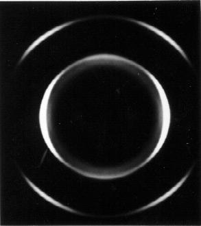
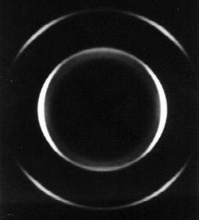
16 187 characterized by sharp melting peaks where the T m values for resins D and E are approximately at 178 C while resin F is 166 C. While the data is absent from this figure, but included within Table 5.4, the non-isothermal melt crystallization temperature (T mc ) is surprisingly not decreased by the additional comonomer. From our investigation, the small difference in T mc should not influence the amount of time the polymer melt is allowed to relax prior to crystallization during extrusion. The reader should recognize, however, that the reported values of T mc are from quiescent melts and not oriented melts such as occur upon melt-extrusion. It expected that because M w and MWD are critical in controlling the rheological and associated relaxation behavior, it is these latter variables that will play critical roles on the resulting orientation and morphological state, as will be discussed. Table 5.4 Molecular weight characteristics for the three POM resins studied. Resin M n (kg/mol) M w (kg/mol) M w / M n T mc ( C) T m ( C) D E F As stated earlier, the planar extensional flow promotes uniaxial symmetry about the MD axis, as verified by Fig. 5.4, which shows the WAXS pattern of a POM precursor obtained with the X-ray beam parallel to the MD. No azimuthal dependence is noted thereby verifying MD as a symmetry axis. 1,2 This type of WAXS pattern occurred for all POM precursors extruded with this film line. In addition, refractometry was performed to determine the refractive index for all three directions (MD, TD & ND) of a POM film. As expected for a uniaxially oriented system, the ND and TD refractive index values were equivalent (ca ) while the refractive index along the MD was different (ca ).
17 188 Endo Temperature ( C) Figure 5.3 Second heating scans of POM (-!-) resin D, (-n-) resin E, and (- -) resin F utilizing a heating rate of 30 C/min.

18 189 ND TD MD Figure 5.4 WAXS photograph of an oriented POM film with X-ray beam parallel to film MD isotropic crystal orientation with respect to the ND of the film.
19 Resins D (Highest M w, Narrow MWD): The WAXS diffraction patterns for films D2 D5 obtained with the beam along the normal direction (ND) are shown in Fig. 5.5a-d. These resin D precursors films were melt-extruded using the conditions #2 #5 described earlier in Table 5.1. In this figure, an arrow indicates the reflection corresponding to the (100) planes. This reflection is utilized to estimate f a and thus f c, i.e., the "c"-axis (chain axis) orientation with respect to the film MD. In Fig. 5.5, the azimuthal dependence of this reflection for each of these precursors is not considerable. However, precursor D2 possesses the greatest azimuthal dependence of those shown. Recall that the azimuthal dependence can be related to f c and thus the precursor, termed D2 produced by extrusion condition #2, is characterized by the greatest level of crystalline orientation along MD for the resin D films. The crystalline orientation for each resin D film, as measured by f c, is listed in Table 5.5 with other pertinent film properties ( T, T m, X c ) to be addressed. These results indicate that f c values are ranked in the following order: D2 > D1 > D3 > D6 > D4 > D5. Note that in calculating f c for the precursors, the meridonal intensity of the (100) planes was ignored and only the azimuthal spread of its equatorial reflection was utilized. The meridonal region of these WAXS patterns, specifically for the (100) reflection, displays different weak intensity levels between the precursors. This bimodal effect feature of a -axis orientation has been noted in other studies 13,14-16,44 on stacked lamellar morphologies, where the a -axis orientation was attributed to lamellar twisting/tilting. It is recognized in Fig. 5.5 that the meridonal intensity is the least intense for the highest oriented sample, D2, but is most intense for the lowest oriented sample D5. This meridonal scattering intensity indicating partial a -axis orientation along MD also decreases as T increases (Table 5.5), as would be expected. In fact, T nearly scales linearly with f c for all the POM films studied see Fig In contrast, neither the melting temperature (T m ), the degree of crystallinity (X c ), or the long spacing (l), change significantly as a function of the resin D processing conditions. In Table 5.5, the measured long spacing for the resin D films remains constant at approximately 152Å, the crystallinity is ca. 51 percent, and the average melting point is 178 C.
20 191 Table 5.5 The crystalline orientation (f c ), total birefringence ( T ), long spacing (l), mass fraction percent crystallinity (X c ), and melting point (T m ) for the resin D precursors. Sample f c, (100) T l (Å) X c (%) T m ( C) D D D D D5 NM D *NM indicates that the azimuthal dependence was not sufficient enough to allow a reasonable estimate of f c.
 TD MD")
 (d)")
21 192 (100) (a) TD MD ND (b) (c) (d)
22 193 Figure 5.5 WAXS photographs of resin D POM films a) D2, b) D3, c) D4, and d) D5. The MD is labeled. Arrows in figure (a) indicate the scattering reflection corresponding to the (100) set-of-planes T f c Figure 5.6 The measured total birefringence ( T ) plotted against the crystalline orientation (f c ) measured from the WAXS.
23 194 AFM micrographs of the same resin D precursors whose WAXS patterns are presented in Fig. 5.5 are shown in Fig It is apparent that a non-planar (twisted) stacked lamellar morphology is predominant in each of these films with the average lateral (long) direction of the lamellae being oriented perpendicular to the film MD. Additionally, larger scale sheaf or fan-like morphologies, indicated by arrows, are evident in the films presented in Fig. 5.7 where the individual fans are oriented perpendicular to the MD. Recognize that the sizes and concentration of these structures increase as either f c or T decrease - compare the AFM micrographs in Figs. 5.7a & d. In the latter case, the superstructure has the 2-dimensional appearance of a spherulitic superstructure that has been described by Wunderlich. 37 In his description, it is stated that this type of spherulitic superstructure emanates (nucleates) from small crystalline lamellae or, in this particular case, more possibly from a small concentration of row-nuclei. This is not the first time spherulitic 11 or sheaf-like 12 morphology has been observed in a process where crystallization of the melt occurs during the application of extrusion stress. Oriented sheaf/fan-like lamellar arrangements were reported by Hashimoto and coworkers for PB-1 blown films. 12 Spherulitic-like superstructures were also found to occur for metallocene catalyzed linear low density polyethylene (LLDPE) blown and cast roll films where the resins possessed similarly narrow MWD values of ca. 2. In some of the LLDPE and all PB-1 films, SALS was observed to produce oriented butterfly-like patterns where the theory describing these patterns has been discussed by Hashimoto and coworkers 12.
 0.")

 D2, b) D3,")

24 195 a) 0.5µm MD TD b) 0.5µm Figure 5.7 AFM phase images of the resin D POM films a) D2, b) D3, c) D4, and d) D5. The MD is labeled. Images are each 3µm x 3µm. MD TD


25 196 c) 0.5µm MD TD d) 0.5µm MD TD (Figure 5.7 cont d)
26 197 Figure 5.8a-d presents the H v SALS patterns for the resin D films D2 through D5, respectively, the same films displayed in Figs. 5.5 and 5.7. Besides the overall 2-fold symmetric butterfly-type pattern, there are inner lobes that decrease in intensity from D2 through D5 or as f c or T decreases. Notice that film D5 has a total absence of any inner lobe in Fig. 5.8d. There are also observable maxima present in the butterfly lobes of films D4 and D5, however, maxima are not present in the SALS patterns for the other two films present ed in Fig These two films are of a higher f c than those that do have maxima. In an attempt to relate the proposed light scattering theory of Hashimoto et al 12 for oriented sheaf morphologies to our experimental H v SALS patterns, a depiction of their oriented fan model is displayed in Fig. 5.9, where the angle γ is half the aperture angle of the fan. This particular parameter will be the only one discussed with respect to its effects on the maxima in the H v SALS patterns. According to this theory, as the angular spread of the oriented fan becomes smaller, γ decreases, the maxima become more elliptic and orients towards the vertical (normal to the sheaf) as well as away from the zero scattering angle (θ = 0). Recalling the AFM results, the sheaf structures were observed to decrease in overall size but also to decrease in γ (angular spread) as f c increased. Thus, based upon this theory of Hashimoto, the resin D H v patterns should be more oriented towards the vertical (MD) as the precursor f c increases. The particular shape of the maxima and the direction, if any, towards which the maxima orient is only evident upon examination of the patterns exhibiting maxima where the theory holds. Additionally, the overall lobes do occur at distinctly higher angles for sample D2 relative to samples D3, D4 and especially D5. This implies that sample D2 possesses smaller superstructural elements as indeed was verified earlier by AFM recall Figs. 5.7a,c, & d. In the case of the lowest oriented film, as observed via AFM and SALS, it does appear to possess the most spherulitic-like texture with distinct maxima observable in the SALS pattern. As is well established, the average radius, R, of an anisotropic spherulite can be determined from the H v pattern 34,38 by use of the relationship 4πR.13 = Sin ( θ / 2) (Eqn. 5.13) λ 4 max m where λ m is the wavelength in the medium and θ max is the radial scattering angle defined by the maximum in the scattering intensity in any lobe of the four fold symmetric H v pattern. The value of λ m is determined by dividing the wavelength of the incident beam (632.8 nm) by the average refractive index of the polymer, (an average isotropic value). Applying this
27 198 equation only to sample D5, the average spherulitic diameter for this sample is approximately 3.2µm, which is comparable to the structure in Fig. 5.7d.
 (c) (d)")


 D4, and")
28 199 (a) TD MD (b) (c) (d) Figure 5.8 H V SALS photographs of resin D POM films a) D2, b) D3, c) D4, and d) D5. The MD is labeled.
29 200 Figure 5.9 Oriented fan model proposed by Hashimoto and coworkers where angle γ is half the aperture angle of the fan. The MD is along the Z-axis. Reprinted with permission from T. Hashimoto.
30 201 To better observe the decrease in superstructure size as f c or T increases, Figs. 5.10a and b are presented; these are AFM height images of the highest and lowest oriented resin D films (D2 & D5, respectively) using a much lower magnification scale (30µm x 30µm). Clearly, much larger superstructures occur in D5, where these are similar in size to that calculated from the SALS patterns. In the higher oriented film, D2, much smaller and more numerous sheaflike structures are evident. Thus, for these resin D films, as f c or T increases as a result of the processing conditions, the morphology becomes smaller and less spherulitic-like moving towards a sheaf-like texture. These fans were also found to decrease in aperture angle (γ) but increase in frequency as f c increased. Note, however, that in each case of the resin D films, the lamellar arrangement was generally stacked with the long dimension perpendicular to the MD axis even in the case of sample D5.

 D2 and b) D5.")
31 202 a) TD 5 µm MD b) TD 5µm MD Figure 5.10 AFM height images of POM resin D films a) D2 and b) D5. The MD is labeled. Images are each 30µm x 30µm.
32 Resin E (Lowest M w, Narrow MWD): The reader will recall that the important difference between resins D and E is the value of M w, resin E possessing a lower value than resin D. It is expected that the resin E films will possess less crystal orientation than the resin D films when processed under equal conditions. This is observed in Figs. 5.11a and b, which display the WAXS diffraction patterns for the precursors from extrusion conditions #2, and #4, respectively, i.e. films E2 and E4. The (100) scattering reflection of the precursor E2 has slightly greater azimuthal dependence than the E4 precursor. The f c value for precursor E2 is observed in Table 5.6 along with other precursor characteristics for the resin E specimens. Although extrusion condition #1 was utilized for resin E to produce film E1, results shown in Table 5.6 suggest that it possessed analogous characteristics to that of film E2. This lack of an extrusion effect between conditions #1 and #2 with respect to resin E is believed due to its lower M w and narrow MWD. However, as in the case of the resin D films, the birefringence values scale with the f c values while the long spacing, melting temperature, and crystallinity remain essentially constant between the three resin E precursors at 157Å, 177 C, and 54 percent, respectively. Table 5.6 The crystalline orientation (f c ), total birefringence ( T ), long spacing (l), mass fraction percent crystallinity (X c ), and melting point (T m ) for the resin E precursors. Sample f c, (100) T l (Å) X c (%) T m ( C) E E E4 NM *NM indicates that the azimuthal dependence was not sufficient enough to allow a reasonable estimate of f c. The morphologies of the resin E precursors are influenced by the process conditions as can be observed in the AFM micrographs displayed in Figs. 5.12a & b. For the more oriented sample, E2, Fig. 5.12a shows the structure of this sample to be a stacked lamellar morphology with evidence of twisting and tilting of the lamellae. The WAXS patterns of these samples also indicate considerable a -axis orientation, thus, verifying there is lamellar twisting or tilting. The lower oriented film, E4 displayed in Fig. 5.12b, is characterized by a more isotropic lamellar superstructure similarly observed for precursor D5. In fact, a few lamellae are observed to return or tilt back along their growth direction.

 E2")
33 204 (a) TD MD ND (b) Figure 5.11 WAXS photographs of resin E POM films a) E2 and b) E4. The MD is labeled.

 E2 and b) E4.")
34 205 a) TD MD 0.5µm b) TD MD MD TD 0.5µm Figure 5.12 AFM phase images of the resin E POM films a) E2 and b) E4. The MD is labeled. Images are 3µm x 3µm.
35 206 As already stated, such a morphology is quite atypical of flow induced morphologies were the application of stress in known to produce higher levels of nucleation than in its absence. A similar H v SALS pattern to the D5 film is also obtained for film E4 as shown in Fig. 5.13b. Note the apparent maxima in the lobes which provides an estimated superstructure size of approximately 4.5µm. The E2 SALS pattern, Fig. 5.13a, is more typical of the resin D films possessing the fan-like structures, which includes the detectable presence of the previously mentioned inner lobes. It also displays a distinct maxima in the butterfly lobes, which leads to an estimated size of roughly 2.3µm. As expected, this value is lower than that for film E4. These patterns also respond in the manner predicted by the light scattering theory described by Hashimoto et al regarding the lobes and their maxima moving towards the MD as the aperture angle decreases, which, in our case, is also as f c decreases. AFM height images using a larger length scale (10µm x 10µm) are presented in Figs. 5.14a and b of precursors E2 and E4. In both cases, the morphologies observed here reflect those shown in Fig at the higher magnification. Specifically, a sheaf-like morphology is observed in the higher oriented film while in the lower oriented film, a more spherulitic-like lamellar arrangement occurs. Additionally, the superstructure number per area or concentration appears to be greater for the film E2 versus E4. These superstructure sizes observed via AFM correlate well with the average superstructure size calculated from the SALS photographs. It is, therefore, recognized that as f c or T increase, the superstructure size decreases while the number of these structures increases as a result of the melt-extrusion conditions.
 TD Figure")

")

36 207 MD (a) (b) TD Figure 5.13 H V SALS photographs of resin E POM films a) E2 and b) E4. The MD is labeled.
 TD 1.")


37 208 a) 1.5µm MD TD b) TD 1.5µm MD Figure 5.14 AFM phase and height micrographs of POM resin E films a) E2 and b) E4. The MD is labeled. The images are 10µm x 10µm.
38 Resin F (Intermediate M w, Broadest MWD): The WAXS diffraction patterns are displayed in Fig for selected resin F meltextruded precursors that arise from the extrusion conditions F1, F2, F3, and F4 described in Table 5.3. It is immediately evident upon examination of these figures, that each display distinctly higher azimuthal dependence of the (100) scattering reflection than has previously been observed for comparable films from either resin D or E, when processed at the same condition (#2). In fact upon calculation of the f c values given in Table 5.7 along with other film properties, the results clearly reflect this statement. The resin F sample F1 possesses the highest f c value for the films from this resin but also for any of the three resins investigated. More important, however, is that upon direct comparison of similarly extruded films, D2, E2 and F2, it is clearly evident that film F2 possesses a significantly higher f c value than either D2 or E2. This result is an obvious consequence of the MWD difference between resin F and resins D and E. The resin F precursor f c values are ranked accordingly in the order F1 > F2 > F5 > F3 > F4. The reader recalls that the presence of a -axis orientation was noted in both the resin D and E films from the evident meridonal intensity of the (100) reflection. Upon further examination of the resin F WAXS patterns, this type of orientation is found as well. Another similarity with the resin D films is that the intensity in the meridonal region decreases with increasing f c, as was expected based upon the works of previous investigators 13,17. Thus the level of lamellar twisting, which is indicated by the presence of some a -axis orientation, decreases as f c increases when comparing resin F samples among each other. The total birefringence, as measured from the samples, also follows this trend. The long spacing, degree of crystallinity, and melting temperature do not change with extrusion conditions as observed previously, where the average values for the resin F films are 128Å, 48 percent, and 166 C, respectively. Table 5.7 The crystalline orientation (f c ), total birefringence ( T ), long spacing (l), mass fraction percent crystallinity (X c ), and melting point (T m ) for the resin F precursors. Sample f c, (100) T l (Å) X c (%) T m ( C) F F F F F

 F1, b) F2, c) F3,")
39 210 (a) TD MD ND (b) (c) (d) Figure 5.15 WAXS photographs of resin F POM films a) F1, b) F2, c) F3, and d) F4. The MD is labeled.
40 211 The morphologies of the same precursors presented in Fig are displayed in Figs. 5.16a-e at the higher magnification utilized previously (3µm x 3µm). A stacked lamellar morphology is present in each film where more planar lamellar textures are noted for the films F1, F2, and F5 while samples F3 and F4 have observably more twisting as shown in Figs a-e, respectively. The precursor F1 appears to possess the most planar texture while the lamellae twist to a greater extent for the precursor F4, however, there is a detectable amount of lamellar twisting for all the resin F precursors, thus verifying the WAXS results. In contrast to the resin D and E films, an overall lack of any observable superstructure is noted in the AFM micrographs for any of the resin F films. The H v SALS patterns also differ from those from resins D and E. Note the absence of any butterfly-type pattern for the selected resin F film results displayed in Fig This is the case even for the lowest oriented precursor F4, which displays a H v SALS pattern similar to that published by one of the authors 40 for a tubular extruded ipp precursor film. The current authors point out that the associated ipp film morphology was a stacked lamellar texture, which is of no surprise since that particular film is utilized as a precursor for ipp commercial microporous films via the MEAUS process. A similar H v pattern occurs for sample F3 that possesses the second lowest f c, except that the scattering is less diffuse at large scattering angles directly along the vertical or MD axis. Recognize also the trend among these H v patterns as f c changes. Specifically, a more rigid rodlike scattering pattern is observed for sample F1 (highest crystal orientation) although it possesses more clover-leaf like scattering with no distinct maxima. 34 These patterns become increasingly more diffuse (less clover-leaf like) as the orientation decreases and the morphology changes from planar to more twisted. However, the light scattering theory accounting for this behavior has not been developed and will not be undertaken here.
 F1, b) F2, c)")
41 212 a) 0.5µm MD TD Figure 5.16 AFM phase images of the resin F films in order of decreasing f c values a) F1, b) F2, c) F5, d) F3, and e) F4. The MD is labeled. Images are each 3µm x 3µm.


42 213 b) TD c) 0.5µm MD TD 0.5µm MD (Figure 5.16 cont d)


43 214 d) e) 0.5µm MD TD 0.5µm MD TD (Figure 5.16 cont d)
 Figure 5.")


 F5, d) F3, and")
44 215 (a) TD MD (b) (c) Figure 5.17 H V SALS photographs of resin F POM films arranged according to decreasing f c or T a) F1, b) F2, c) F5, d) F3, and e) F4. The MD is labeled.

45 216 (d) (e) MD TD (Figure 5.17 cont d)
46 217 AFM height images at lower magnifications for these resin F precursors are displayed in Figs. 5.18a & b. In the case of film F1, a highly oriented fibril texture appears to be present. This morphology is somewhat apparent in the previous higher magnification phase image of this film, Fig 5.16a. Recalling this figure, the reader will recognize that there is the appearance of a larger scale layer-like morphology with its long axis aligned parallel with the MD which is better observed via the height image in Fig. 5.18a. The other film, F3, appears to have no trace of such structures. Upon re-examination of the higher resolution AFM micrograph in Fig. 5.18b, there is a lack of any observable layer-like structure. However, in all AFM micrographs there is an absence of any visible shish or row-nuclei, and the WAXS patterns do not display additional sharp equatorial reflections superimposed upon the (100) reflection. Sharp equatorial superimposed reflections in WAXS patterns have been shown to occur in the case of HDPE tubular films that did possess visibly evident shish-kebob morphologies. 2 Thus, the observed morphologies may not contain long fibril structures based on the above WAXS and lack of any observable row-nuclei in the AFM micrographs. However, if there are large long fibrillar nuclei in the film F1, they would be detrimental to the formation of a microporous morphology upon uniaxial-stretching. This is due to the pinning effect caused by these structures during stretching thus hindering lamellar separation. 41 This will be addressed in the second report of this study 9, where a selected number of the resin D and especially resin F precursors will be followed for the effects of annealing and stretching variable combinations on the resulting morphology and microporosity. As pointed out, the differences in the resin characteristics were noted to influence the film morphology and orientation state of the precursors as well as the long spacing, melting temperature, and crystallinity. The long spacing, melting temperature, and crystallinity are, of course, a consequence of the added comonomer present in resin F resulting in a disruption of the chain symmetry thereby leading to greater imperfection in the crystalline phase. This greater imperfection in the crystalline phase then produces a lower melting temperature and level of crystallinity versus precursors from the resins polymerized without the presence of the comonomer (resins D and E). Since the defects caused by the added comonomer are likely to be excluded from the crystalline phase, the crystalline lamellae will be smaller as reflected by the smaller long spacing, recall Tables This result is also shown in Fig. 5.19, where the corresponding SAXS profile of sample F2 is given for the slit-smeared intensity versus scattering vector, s. The corresponding SAXS profiles for the similarly extruded samples D2
47 218 and E2 are also displayed for comparison purposes. These SAXS profiles were obtained by passing the X-ray beam along the ND and obtaining the scan along the MD. As might be expected, these profiles clearly show a well-defined first order peak along with a weaker second order peak. (Note that this data is slit-smeared and thus the first and second order peaks are not as prominent (intense) or narrow as they would be if desmearing had been undertaken.) The SAXS data in addition to that presented in Tables indicates the effect the ethylene oxide comonomer present in resin F has on the lamellar thickness. Neglecting differences in the long spacing, both resin D, E, and F precursors have similar SAXS profiles suggesting that the resins, when extruded under analogous conditions, possess similar lamellar morphologies.


48 219 a) TD 5µm MD b) TD 5µm MD Figure 5.18 AFM height images of the resin F POM films a) F1 and b) F2. The MD is labeled. Images are each 30µm x 30µm.
LIST OF FIGURES. 2.1 Schematic of the types of row structure with the respective extrusion condition and the main features of the PE WAXS patterns.
 ix LIST OF FIGURES FIGURE 2.1 Schematic of the types of row structure with the respective extrusion condition and the main features of the PE WAXS patterns. 33 2.2 Tensile curves of hard elastic Celcon
CHAPTER IV ABSTRACT. Matthew B. Johnson Chapter IV PMP Annealing & Stretching
 115 CHAPTER IV Microporous Membranes of Isotactic Poly(4-methyl-1-pentene) from a Melt-Extrusion Process: (II) Effects of Thermal Annealing and Stretching on Porosity ABSTRACT A two part study utilizing
Matthew B. Johnson Chapter III PMP Melt-Extrusion CHAPTER III
 78 CHAPTER III Microporous Membranes of Isotactic Poly(4-methyl-1-pentene) from a Melt-Extrusion Process: (I) Effects of Resin Variables and Extrusion Conditions ABSTRACT A study utilizing isotactic poly(4-methyl-1-pentene)
Microporous Membranes of Isotactic Poly(4-methyl-1- pentene) from amelt-extrusion Process. II. Effects of Thermal Annealing and Stretching on Porosity
 from amelt-extrusion Process. II. Effects of Thermal Annealing and Stretching on Porosity") Microporous Membranes of Isotactic Poly(4-methyl-1- pentene) from amelt-extrusion Process. II. Effects of Thermal Annealing and Stretching on Porosity MATTHEW B. JOHNSON, GARTH L. WILKES Virginia Tech,
Microporous Membranes of Isotactic Poly(4-methyl-1- pentene) from amelt-extrusion Process. II. Effects of Thermal Annealing and Stretching on Porosity MATTHEW B. JOHNSON, GARTH L. WILKES Virginia Tech,
Polyolefins. James L. White, Choi. Processing, Structure Development, and Properties ISBN Leseprobe 3
 Polyolefins James L. White, Choi Processing, Structure Development, and Properties ISN 3-446-22962-0 Leseprobe 3 Weitere Informationen oder estellungen unter http://www.hanser.de/3-446-22962-0 sowie im
Polyolefins. James L. White, Choi. Processing, Structure Development, and Properties ISBN Leseprobe 2
 Polyolefins James L. White, Choi Processing, Structure Development, and Properties ISBN 3-446-96-0 Leseprobe Weitere Informationen oder Bestellungen unter http://www.hanser.de/3-446-96-0 sowie im Buchhandel
When non-branched linear polymers such as polyethylene (PE) crystallizes from the melt,
 crystallizes from the melt,") Polarizing Optical Microscopy: Birefringence Analysis and the Effect of Different Crystallization Temperatures on the Spherulitic Microstructure Eman Mousa Alhajji North Carolina State University Department
Polarizing Optical Microscopy: Birefringence Analysis and the Effect of Different Crystallization Temperatures on the Spherulitic Microstructure Eman Mousa Alhajji North Carolina State University Department
conference papers Micro-focus X-ray scanning on layers of smectic superstructures
 Micro-focus X-ray scanning on layers of smectic superstructures I. Gurke 1, *. Wutz 1, D. Gieseler 1, B. Janssens 1, F. Heidelbach 2,. Riekel 2, H.R. Kricheldorf 1 1 Universität Hamburg, Institut für Technische
Spherulitic Morphologies of Poly(ethylene terephthalate), Poly(ethylene 2,6-naphthalate), and Their Blend
, Poly(ethylene 2,6-naphthalate), and Their Blend") Macromolecular Research, Vol. 10, No. 1, pp 44-48 (2002) Spherulitic Morphologies of Poly(ethylene terephthalate), Poly(ethylene 2,6-naphthalate), and Their Blend Jong Kwan Lee and Kwang Hee Lee* Center
Macromolecular Research, Vol. 10, No. 1, pp 44-48 (2002) Spherulitic Morphologies of Poly(ethylene terephthalate), Poly(ethylene 2,6-naphthalate), and Their Blend Jong Kwan Lee and Kwang Hee Lee* Center
Chemical Engineering 160/260 Polymer Science and Engineering. Lecture 17: Kinetics and Thermodynamics of Crystallization February 26, 2001
 Chemical Engineering 160/260 Polymer Science and Engineering Lecture 17: Kinetics and Thermodynamics of Crystallization February 26, 2001 Sperling, Chapter 6 Objectives To rationalize the observed morphology
CHAPTER 4 LANGMUIR FILMS AT THE AIR/WATER INTERFACE
 CHAPTER 4 GROWTH OF POLY(ε-CAPROLACTONE) CRYSTALS IN LANGMUIR FILMS AT THE AIR/WATER INTERFACE Reproduced with permission from: Li, B.; Wu, Y.; Liu, M.; Esker, A. R. Brewster Angle Microscopy Study of
Chapter 3 Basic Crystallography and Electron Diffraction from Crystals. Lecture 9. Chapter 3 CHEM Fall, L. Ma
 Chapter 3 Basic Crystallography and Electron Diffraction from Crystals Lecture 9 Outline The geometry of electron diffraction Crystallography Kinetic Theory of Electron diffraction Diffraction from crystals
Single crystal X-ray diffraction. Zsolt Kovács
 Single crystal X-ray diffraction Zsolt Kovács based on the Hungarian version of the Laue lab description which was written by Levente Balogh, Jenő Gubicza and Lehel Zsoldos INTRODUCTION X-ray diffraction
9/28/2013 9:26 PM. Chapter 3. The structure of crystalline solids. Dr. Mohammad Abuhaiba, PE
 Chapter 3 The structure of crystalline solids 1 2 Why study the structure of crystalline solids? Properties of some materials are directly related to their crystal structure. Significant property differences
Crystallization kinetics of PHB and its blends 3.1 Introduction
 3 3.1 Introduction The crystallization process is a transition from liquid phase (melts) into solid phase after cooling. The crystallization kinetics of PHB and its blends is investigated by using differential
High-Pressure Crystallization of Poly(1-butene)
") High-Pressure Crystallization of Poly(1-butene) JIŘÍ KALOUS, LUBOMÍR BENÍČEK, ROMAN ČERMÁK Department of Polymer Engineering Tomas Bata University Náměstí T.G.Masaryka 275, 762 72, Zlín CZECH REPUBLIC
High-Pressure Crystallization of Poly(1-butene) JIŘÍ KALOUS, LUBOMÍR BENÍČEK, ROMAN ČERMÁK Department of Polymer Engineering Tomas Bata University Náměstí T.G.Masaryka 275, 762 72, Zlín CZECH REPUBLIC
9/29/2014 8:52 PM. Chapter 3. The structure of crystalline solids. Dr. Mohammad Abuhaiba, PE
 1 Chapter 3 The structure of crystalline solids 2 Home Work Assignments HW 1 2, 7, 12, 17, 22, 29, 34, 39, 44, 48, 53, 58, 63 Due Sunday 12/10/2014 Quiz # 1 will be held on Monday 13/10/2014 at 11:00 am
Strain. Two types of stresses: Usually:
 Stress and Texture Strain Two types of stresses: microstresses vary from one grain to another on a microscopic scale. macrostresses stress is uniform over large distances. Usually: macrostrain is uniform
A study of plastic plateau disappearance in stress-strain curve of annealed polypropylene films during stretching
 The 2012 World Congress on Advances in Civil, Environmental, and Materials Research (ACEM 12) Seoul, Korea, August 26-30, 2012 A study of plastic plateau disappearance in stress-strain curve of annealed
Optical microscopy Theoretical background Galina Kubyshkina
 Optical microscopy Theoretical background Galina Kubyshkina Elektromaterial Lendava d.d., Slovenia Crystalline materials presence of a unit (cell), which is periodically repeated in space regular structure
Chapter 5. Differential Scanning Calorimetry
 Chapter 5. Differential Scanning Calorimetry 5.1 Introduction The discussion in Chapter 2 clearly illustrates the fact that the crystallization process and the resulting morphology in polymers are largely
3.5.7 Flow Through Simple Dies
 152 3 Fundamentals of Polymers isothermal spinning of a Newtonian fluid and predicted the critical draw ratio of 20.210. Below the critical draw ratio, any disturbance along the filament is dampened out
9/16/ :30 PM. Chapter 3. The structure of crystalline solids. Mohammad Suliman Abuhaiba, Ph.D., PE
 Chapter 3 The structure of crystalline solids 1 Mohammad Suliman Abuhaiba, Ph.D., PE 2 Home Work Assignments HW 1 2, 7, 12, 17, 22, 29, 34, 39, 44, 48, 53, 58, 63 Due Sunday 17/9/2015 3 Why study the structure
SECTION A. NATURAL SCIENCES TRIPOS Part IA. Friday 4 June to 4.30 MATERIALS AND MINERAL SCIENCES
 NATURAL SCIENCES TRIPOS Part IA Friday 4 June 1999 1.30 to 4.30 MATERIALS AND MINERAL SCIENCES Answer five questions; two from each of sections A and B and one from section C. Begin each answer at the
Technical articles Micro-area X-ray diffraction measurement by SmartLab μ
 Technical articles Micro-area X-ray diffraction measurement by SmartLab μhr diffractometer system with ultra-high brilliance microfocus X-ray optics and two-dimensional detector HyPix-3000 Yuji Shiramata*
Morphology Development during Biaxial Stretching of Polypropylene Films
 Morphology Development during Biaxial Stretching of Polypropylene Films L.Capt(1)(2), M. R. Kamal(1), H. Münstedt(2), K. Stopperka(3) and J. Sänze(3) (1) Department of Chemical Engineering, McGill University
BLOCK COPOLYMERS ORGANIZATION AT INTERFACE
 THE 19 TH INTERNATIONAL CONFERENCE ON COMPOSITE MATERIALS BLOCK COPOLYMERS ORGANIZATION AT INTERFACE D.Fischer, S. Bistac *, M. Brogly, Université de Haute Alsace, LPIM, Mulhouse France * Corresponding
WIDE, HIGHLY ORIENTED MESOPHASE PITCH-BASED CARBON TAPES: MECHANICAL PROPERTIES OF THE TAPES AND OF TAPE-DERIVED CARBON SPRINGS
 WIDE, HIGHLY ORIENTED MESOPHASE PITCH-BASED CARBON TAPES: MECHANICAL PROPERTIES OF THE TAPES AND OF TAPE-DERIVED CARBON SPRINGS A. Antonarulrajah, A. Westwood*, E. Galanopoulos, A. Eagles, J. Sansom and
THE EFFECT OF BIAXIAL ORIENTATION PROCESSING CONDITIONS ON IMMISCIBLE POLYMER BLENDED SHEET
 THE EFFECT OF BIAXIAL ORIENTATION PROCESSING CONDITIONS ON IMMISCIBLE POLYMER BLENDED SHEET Jennifer K. Lynch, Ph.D., Rutgers University Thomas J. Nosker, Ph.D., Rutgers University James D. Idol, Ph.D.,
Thickness Uniformity of Double Bubble Tubular Film Process for Producing Biaxially Oriented PA 6 Film
 FILM M. Takashige 1 *, T. Kanai 2, T. Yamada 3 1 Idemitsu Unitech Co., Ltd., Hyogo, Japan 2 Idemitsu Petrochemical Co., Ltd., Chiba, Japan 3 Kanazawa University, Ishikawa, Japan Thickness Uniformity of
Ionic Aggregates in Zn- and Na-neutralized Poly(ethylene-ran-methacrylic acid)
") University of Pennsylvania ScholarlyCommons Departmental Papers (MSE) Department of Materials Science & Engineering December 2005 Ionic Aggregates in Zn- and Na-neutralized Poly(ethylene-ran-methacrylic
University of Pennsylvania ScholarlyCommons Departmental Papers (MSE) Department of Materials Science & Engineering December 2005 Ionic Aggregates in Zn- and Na-neutralized Poly(ethylene-ran-methacrylic
Supporting Online Material for
 www.sciencemag.org/cgi/content/full/316/5827/1014/dc1 Supporting Online Material for Molecular Basis of the Shish-Kebab Morphology in Polymer Crystallization Shuichi Kimata, Takashi Sakurai, Yoshinobu
Orientation / Texture Polyethylene films
 Application Note PT-002 Orientation / Texture Polyethylene films Polyethylene (PE) film is one of the most commonly used polymeric products and orientation measurements of this material are of great interest.
X-ray diffraction
 2.2.3.- X-ray diffraction 2.2.3.1.- Origins and fundamentals of the technique The first experimental evidence concerning x-ray diffraction was given by Max von Laue who in 1912 demonstrated that x-rays
Fundamentals of X-ray diffraction and scattering
 Fundamentals of X-ray diffraction and scattering Don Savage dsavage@wisc.edu 1231 Engineering Research Building (608) 263-0831 X-ray diffraction and X-ray scattering Involves the elastic scattering of
Thin Film Confinement of a Spherical Block Copolymer via Forced Assembly Co-extrusion
 Supplementary Information Thin Film Confinement of a Spherical Block Copolymer via Forced Assembly Co-extrusion Tiffani M. Burt a,b, Seyedali Monemian a, Alex M. Jordan a,b, and LaShanda T. J. Korley a,b*
NEW DEVELOPMENTS IN BETA NUCLEATION OF POLYPROPYLENE AND LASER PRINTING OF MICROPOROUS FILMS
 NEW DEVELOPMENTS IN BETA NUCLEATION OF POLYPROPYLENE AND LASER PRINTING OF MICROPOROUS FILMS Philip Jacoby, V.P. of Technology, Mayzo Corporation, Suwanee, GA Abstract: Beta nucleation can be used to produce
Application of Atomic Force Microscopy (AFM) in Polymer Materials
 in Polymer Materials") Application of Atomic Force Microscopy (AFM) in Polymer Materials Application Note Jing-jiang Yu and Sergei N. Magonov Introduction Atomic force microscopy (AFM) is a powerful characterization tool for
Application of Atomic Force Microscopy (AFM) in Polymer Materials Application Note Jing-jiang Yu and Sergei N. Magonov Introduction Atomic force microscopy (AFM) is a powerful characterization tool for
Diffraction Basics. The qualitative basics:
 The qualitative basics: Diffraction Basics Coherent scattering around atomic scattering centers occurs when x-rays interact with material In materials with a crystalline structure, x-rays scattered in
The growth of patterned ceramic thin films from polymer precursor solutions Göbel, Ole
 University of Groningen The growth of patterned ceramic thin films from polymer precursor solutions Göbel, Ole IMPORTANT NOTE: You are advised to consult the publisher's version (publisher's PDF) if you
ANNEALING OF UNIAXIALLY ORIENTED ISOTACTIC POLYPROPYLENE
 ANNEALING OF UNIAXIALLY ORIENTED ISOTACTIC POLYPROPYLENE MARTINA HRIBOA a, FRANTISEK RYBNIKAR b, JAROSLA KUCERA c, and JIRI SADILEK c a University Institute, Tomas Bata University in Zlin, Nad Ovcirnou
This lecture is part of the Basic XRD Course.
 This lecture is part of the Basic XRD Course. Basic XRD Course 1 A perfect polycrystalline sample should contain a large number of crystallites. Ideally, we should always be able to find a set of crystallites
UNIT V -CRYSTAL STRUCTURE
 UNIT V -CRYSTAL STRUCTURE Solids are of two types: Amorphous and crystalline. In amorphous solids, there is no order in the arrangement of their constituent atoms (molecules). Hence no definite structure
Abstract. Experimental. Introduction. for the polymer showing the lowest crystallinity is very advantageous for a number of applications.
 Elastic Nonwoven Fabrics from Polyolefin Elastomers by S. Srinivas, C. Y. Cheng (Consultant), N. Dharmarajan, and G. Racine ExxonMobil Chemical, 52 Bayway Drive, Baytown, TX 7752 Abstract Vistamaxx Specialty
DAVID L. GODSHALL DOCTOR OF PHILOSOPHY. Chemical Engineering APPROVED: G.L. Wilkes, Chairman. October, 2002 Blacksburg, VA
 INVESTIGATIONS OF STRUCTURE PROPERTY RELATIONSHIPS IN SEMICRYSTALLINE THERMOPLASTIC POLYMERS: BLOWN POLYETHYLENE FILMS AND POLYACRYLONITRILE COPOLYMERS by DAVID L. GODSHALL Dissertation submitted to the
Effect of Processing Parameters on Polypropylene Film Properties
 Vol.2, Issue.5, Sep.-Oct. 2012 pp-3056-3060 ISSN: 2249-6645 Effect of Processing Parameters on Polypropylene Film Properties Ikilem Gocek 1, Sabit Adanur 2 1 (Department of Textile Engineering, Istanbul
The object of this experiment is to test the de Broglie relationship for matter waves,
 Experiment #58 Electron Diffraction References Most first year texts discuss optical diffraction from gratings, Bragg s law for x-rays and electrons and the de Broglie relation. There are many appropriate
EFFECTS OF MACHINE DIRECTION ORIENTATION (MDO) ON THE MOISTURE AND OXYGEN PROPERTIES OF HMW-PE FILMS
 ON THE MOISTURE AND OXYGEN PROPERTIES OF HMW-PE FILMS") EFFECTS OF MACHINE DIRECTION ORIENTATION (MDO) ON THE MOISTURE AND OXYGEN PROPERTIES OF HMW-PE FILMS EFFECTS OF MACHINE DIRECTION ORIENTATION (MDO) ON THE MOISTURE AND OXYGEN PROPERTIES OF HMW-PE FILMS
EFFECTS OF MACHINE DIRECTION ORIENTATION (MDO) ON THE MOISTURE AND OXYGEN PROPERTIES OF HMW-PE FILMS EFFECTS OF MACHINE DIRECTION ORIENTATION (MDO) ON THE MOISTURE AND OXYGEN PROPERTIES OF HMW-PE FILMS
3. SOLID STATE STRUCTURE-PROPERTY RELATIONSHIP OF SEMICRYSTALLINE POLY(ETHER-BLOCK-AMIDE) PEBAX THERMOPLASTIC ELASTOMERS
 PEBAX THERMOPLASTIC ELASTOMERS") 3. SOLID STATE STRUCTURE-PROPERTY RELATIONSHIP OF SEMICRYSTALLINE POLY(ETHER-BLOCK-AMIDE) PEBAX THERMOPLASTIC ELASTOMERS 3.1 CHAPTER SUMMARY The solid state structure-property behavior was investigated
3. SOLID STATE STRUCTURE-PROPERTY RELATIONSHIP OF SEMICRYSTALLINE POLY(ETHER-BLOCK-AMIDE) PEBAX THERMOPLASTIC ELASTOMERS 3.1 CHAPTER SUMMARY The solid state structure-property behavior was investigated
LECTURE 7. Dr. Teresa D. Golden University of North Texas Department of Chemistry
 LECTURE 7 Dr. Teresa D. Golden University of North Texas Department of Chemistry Diffraction Methods Powder Method For powders, the crystal is reduced to a very fine powder or microscopic grains. The sample,
METHOD TO EVALUATE BIAXIAL STRETCH RATIOS IN STRETCH BLOW MOLDING
 METHOD TO EVALUATE BIAXIAL STRETCH RATIOS IN STRETCH BLOW MOLDING Masoud Allahkarami 1, 2, Sudheer Bandla 2, and Jay C. Hanan 1 1 Mechanical and Aerospace Engineering, Oklahoma State University, Tulsa,
Chapter 2. Metallic Glass Honeycombs. Introduction
 8 Chapter 2 Metallic Glass Honeycombs Introduction Due to the fact that they undergo a glass transition and are stable as an undercooled liquid over a large range of temperatures for a significant amount
Influence of extrusion coating processing conditions on structure and tensile properties of some polyethylene grades
 ANNUAL TRANSACTIONS OF THE NORDIC RHEOLOGY SOCIETY, VOL. 1, 22 Influence of extrusion coating processing conditions on structure and tensile properties of some polyethylene grades Nils Toft and Mikael
Measurement of Residual Stress by X-ray Diffraction
 Measurement of Residual Stress by X-ray Diffraction C-563 Overview Definitions Origin Methods of determination of residual stresses Method of X-ray diffraction (details) References End Stress and Strain
11.3 The analysis of electron diffraction patterns
 11.3 The analysis of electron diffraction patterns 277 diameter) Ewald reflecting sphere, the extension of the reciprocal lattice nodes and the slight buckling of the thin foil specimens all of which serve
EXTRUSION OF ELASTOMER FILM, EFFECTS OF ELASTOMER DESIGN ON CHILL ROLL STICKING
 EXTRUSION OF ELASTOMER FILM, EFFECTS OF ELASTOMER DESIGN ON CHILL ROLL STICKING Mary Ann Jones, Todd Hogan, and Sarah Gassner, The Dow Chemical Company, Midland, MI Abstract Sticking of plastic webs to
MICRO-THERMAL, X-RAY AND RAMAN ANALYSES OF POLYOLEFIN INTERFACES
 MICRO-THERMAL, X-RAY AND RAMAN ANALYSES OF POLYOLEFIN INTERFACES T. Nishino, M. Kotera, D. Izumo, Y.Urushihara Graduate School of Engineering, Kobe University Rokko, Nada, Kobe 657-8501, Japan tnishino@kobe-u.ac.jp
QUANTITATIVE POLE FIGURE ANALYSIS OF ORIENTED POLYETHYLENE FILMS
 Copyright(c)JCPDS-International Centre for Diffraction Data 2000,Advances in X-ray Analysis,Vol.43 141 QUANTITATIVE POLE FIGURE ANALYSIS OF ORIENTED POLYETHYLENE FILMS J. H. Butler, S. MI. Wapp and F.
Physics 6180: Graduate Physics Laboratory. Experiment CM5: X-ray diffraction and crystal structures
 Physics 6180: Graduate Physics Laboratory Experiment CM5: X-ray diffraction and crystal structures References: Preston and Dietz, Expt. 10 pp. 180-197 Eisberg and Resnick, Quantum Physics, Sec. 9 Kittel,
CURVATURE MEASUREMENTS OF STRESSED SURFACE-ACOUSTIC- WAVE FILTERS USING BRAGG ANGLE CONTOUR MAPPING
 86 CURVATURE MEASUREMENTS OF STRESSED SURFACE-ACOUSTIC- WAVE FILTERS USING BRAGG ANGLE CONTOUR MAPPING ABSTRACT Paul M. Adams The Aerospace Corporation Los Angeles, CA 90009 Surface-acoustic-wave (SAW)
TIE-27: Stress in optical glass
 PAGE 1/13 0 Introduction The amount and distribution of permanent inherent stress in glass depends on the annealing conditions, the glass type, size and geometry of the glass part This stress causes birefringence
THE ANALYSIS OF STRESS DISTRIBUTION BASED ON MEASUREMENTS USING TWO METHODS OF X-RAY APPLICATION
 182 THE ANALYSIS OF STRESS DISTRIBUTION BASED ON MEASUREMENTS USING TWO METHODS OF X-RAY APPLICATION ABSTRACT Barbara Kucharska Institute of Materials Engineering, Czestochowa University of Technology,
Supporting Information
 Supporting Information Novel Interwoven Polymer Composites via Dual- Electrospinning with Shape Memory/Self-healing Properties Jaimee M. Robertson, Hossein Birjandi Nejad, Patrick T. Mather* Syracuse Biomaterials
A vapor (or gas) needs a completely enclosed container to have a definite volume; it will readily take on any shape imposed.
 needs a completely enclosed container to have a definite volume; it will readily take on any shape imposed.") Overview: Amorphous and crystalline solid states. States of matter. General description. A vapor (or gas) needs a completely enclosed container to have a definite volume; it will readily take on any shape
Overview: Amorphous and crystalline solid states. States of matter. General description. A vapor (or gas) needs a completely enclosed container to have a definite volume; it will readily take on any shape
(aw = l20,000), which had been extruded at 170 C up
, which had been extruded at 170 C up") Effects of Shearing Conditions on Crystalline Orientation and Relaxation in Polyethylene E. S. HSIUE, R. E. ROBERTSON,* and G. S. Y. YEH Department of Chemical Engineering and Macromolecular Research Center
Effects of Shearing Conditions on Crystalline Orientation and Relaxation in Polyethylene E. S. HSIUE, R. E. ROBERTSON,* and G. S. Y. YEH Department of Chemical Engineering and Macromolecular Research Center
Seminar: Structural characterization of photonic crystals based on synthetic and natural opals. Olga Kavtreva. July 19, 2005
 Seminar: Structural characterization of photonic crystals based on synthetic and natural opals Olga Kavtreva July 19, 2005 Abstract Novel class of dielectric structures with a refractive index which exhibits
Introduction to Polymer-Dispersed Liquid Crystals
 Introduction to Polymer-Dispersed Liquid Crystals Polymer-dispersed liquid crystals (PDLCs) are a relatively new class of materials that hold promise for many applications ranging from switchable windows
F. Sadeghi, A. Ajji, P. J. Carreau
 Study of Polypropylene Morphology Obtained from Blown and Cast Film Processes: Initial Morphology Requirements for Making Porous Membrane by Stretching F. Sadeghi, A. Ajji, P. J. Carreau To cite this version:
Endex Foam Extrusion General Information Guide
 Endex International Innovation for the Future Endex Foam Extrusion General Information Guide Section 01 - Foam Extrusion Foam extrusion, in simple terms, consists of mixing a chemical foaming agent with
CURE PROCESS MONITORING OF CURVED COMPOSITE WITH INTERLAMINAR TOUGHENED LAYERS
 CURE PROCESS MONITORING OF CURVED COMPOSITE WITH INTERLAMINAR TOUGHENED LAYERS The University of Tokyo, Graduate School of Frontier Science, 5-1-5, Kashiwanoha, Kashiwashi, Chiba 277-8561, Japan, sawaguchi@smart.k.u-tokyo.ac.jp.
Identification of Crystal Structure and Lattice Parameter. for Metal Powders Using X-ray Diffraction. Eman Mousa Alhajji
 Identification of Crystal Structure and Lattice Parameter for Metal Powders Using X-ray Diffraction Eman Mousa Alhajji North Carolina State University Department of Materials Science and Engineering MSE
Lab 4 Module γ 1. Short range order
 3.014 Materials Laboratory Dec. 9 th Dec. 14 th, 2005 Lab 4 Module γ 1 Short range order OBJECTIVES 9 Understand structure of amorphous materials 9 Learn principles of x-ray scattering from amorphous materials
3. Anisotropic blurring by dislocations
 Dynamical Simulation of EBSD Patterns of Imperfect Crystals 1 G. Nolze 1, A. Winkelmann 2 1 Federal Institute for Materials Research and Testing (BAM), Berlin, Germany 2 Max-Planck- Institute of Microstructure
Silicone masterbatch additives for improved plastics processing
 Gummi Fasern Kunststoffe, No. 11, 2000, p. 778 masterbatch additives for improved plastics processing V.B. John and H. Rubroeder* Translation submitted by C. Hinchliffe Selected from International Polymer
Directional Amorphization of Boron Carbide Subjected to Laser Shock Compression
 Supporting Information Directional Amorphization of Boron Carbide Subjected to Laser Shock Compression This PDF file contains: Figures S1 to S4 Supplementary Text : 1. Materials and initial characterization
Highly insulating polyethylene blends for HVDC power cables
 Supporting Information Highly insulating polyethylene blends for HVDC power cables Mattias G. Andersson 1, Jonna Hynynen 1, Mats R. Andersson 2, Villgot Englund 3, Per-Ola Hagstrand 3, Thomas Gkourmpis
Chapter 15 Part 2. Mechanical Behavior of Polymers. Deformation Mechanisms. Mechanical Behavior of Thermoplastics. Properties of Polymers
 Mechanical Behavior of Polymers Chapter 15 Part 2 Properties of Polymers Wide range of behaviors Elastic-Brittle (Curve A) Thermosets and thermoplastics Elastic-Plastic (Curve B) Thermoplastics Extended
Atomic Densities. Linear Density Number of atoms per length whose centers lie on the direction vector for a specific crystallographic direction.
 Atomic Densities Linear Density Number of atoms per length whose centers lie on the direction vector for a specific crystallographic direction. Planar Density Number of atoms per unit area that are centered
Crystallization Behavior of Polyamide-6 Microcellular Nanocomposites*
 Crystallization Behavior of Polyamide-6 Microcellular Nanocomposites* MINGJUN YUAN, LIH-SHENG TURNG, SHAOQIN GONG AND ANDREAS WINARDI Polymer Engineering Center Department of Mechanical Engineering University
COMPARATIVE STRUCTURE DEVELOPMENT OF VARIOUS POLYOLEFINS IN INJECTION MOLDING PROCESS. A Dissertation. Presented to the
 COMPARATIVE STRUCTURE DEVELOPMENT OF VARIOUS POLYOLEFINS IN INJECTION MOLDING PROCESS A Dissertation Presented to the The Graduate Faculty of the University In Partial Fulfillment of the Requirements for
Effect of Material Properties and Processing Conditions on PP Film Casting
 Effect of Material Properties and Processing Conditions on PP Film Casting Kenneth Aniunoh and Graham Harrison Department of Chemical and Biomolecular Engineering and Center for Advanced Engineering Fibers
Local buckling of slender aluminium sections exposed to fire. Residual stresses in welded square hollow sections of alloy 5083-H111
 Netherlands Institute for Metals Research Eindhoven University of Technology TNO Built Environment and Geosciences Report no. 8 Local buckling of slender aluminium sections exposed to fire Residual stresses
Rietveld refinement of ZrSiO 4 : application of a phenomenological model of anisotropic peak width
 Rietveld refinement of ZrSiO 4 : application of a phenomenological model of anisotropic peak width A. Sarkar, P. Mukherjee, P. Barat Variable Energy Cyclotron Centre 1/A Bidhan Nagar, Kolkata 700064, India
T E C H N O L O G Y Form No K.W. Swogger, et. al. UNRESTRICTED May be shared with anyone May 2003
 T E C H N O L O G Y Form No. 746-03801 MATERIAL CLASSIFICATION AND APPLICATIONS OF NEW PROPYLENE-ETHYLENE COPOLYMERS K. W. Swogger 2, B. Poon 1, C. H. Stephens 1, P. Ansems 2, S. Chum 2, A. Hiltner 1,
Crystallization under Strain and Resultant Orientation of Poly(ɛ-caprolactone) in Miscible Blends
 in Miscible Blends") 1218 Macromolecules 1999, 32, 1218-1225 Crystallization under Strain and Resultant Orientation of Poly(ɛ-caprolactone) in Miscible Blends Yue Zhao,*,, Daniel Keroack,, and Robert Prud homme*, Département
1218 Macromolecules 1999, 32, 1218-1225 Crystallization under Strain and Resultant Orientation of Poly(ɛ-caprolactone) in Miscible Blends Yue Zhao,*,, Daniel Keroack,, and Robert Prud homme*, Département
Chapter 5. Morphology Development in HDPE/Copolymer Blends: Quiescent and Flow-Induced Crystallization
 V - 1 Chapter 5 Morphology Development in HDPE/Copolymer Blends: Quiescent and Flow-Induced Crystallization 5.1 INTRODUCTION...V-2 5.2 EXPERIMENTAL METHODS...V-4 5.2.1 Materials...V-4 5.2.2 Differential
Author(s) Hyon, S.-H.; Taniuchi, H.; Kitamaru.
 Hyon, S.-H.; Taniuchi, H.; Kitamaru.") Title The Orientation of Crystal Planes i under Compression (Special Issue on Author(s) Hyon, S.-H.; Taniuchi, H.; Kitamaru Citation Bulletin of the Institute for Chemi University (1973), 51(2): 91-103
Title The Orientation of Crystal Planes i under Compression (Special Issue on Author(s) Hyon, S.-H.; Taniuchi, H.; Kitamaru Citation Bulletin of the Institute for Chemi University (1973), 51(2): 91-103
Calcium Carbonate in Blown HDPE Film
 Calcium Carbonate in Blown HDPE Film New Developments to Increase Productivity and Profitability by Gil Morieras - Marketing Manager Polyolefines (Omya) and Dr. Gerard Schaeffer (GS Technology) Many interesting
Characterization of Materials Using X-Ray Diffraction Powder Diffraction
 Praktikum III, Fall Term 09 Experiment P1/P2; 23.10.2009 Characterization of Materials Using X-Ray Diffraction Powder Diffraction Authors: Michael Schwarzenberger (michschw@student.ethz.ch) Philippe Knüsel
BLOCK COPOLYMER PHOTONIC GEL FOR DETECTING INTERFACIAL SEPARATION
 BLOCK COPOLYMER PHOTONIC GEL FOR DETECTING INTERFACIAL SEPARATION Edwin P. Chan, Materials Research Engineer, National Institute of Standards and Technology, Gaithersburg, MD Introduction Mechanochromism,
Nanoconfinement Crystallization of Frustrated Alkyl Groups: Crossover of Mesophase to Crystalline Structure
 Nanoconfinement Crystallization of Frustrated Alkyl Groups: Crossover of Mesophase to Crystalline Structure Haifeng Shi,,,* Haixia Wang, John H. Xin, Xingxiang Zhang, and Dujin Wang, * State Key Laboratory
Carbon nanostructures. (http://www.mf.mpg.de/de/abteilungen/schuetz/index.php?lang=en&content=researchtopics&type=specific&name=h2storage)
") Carbon nanostructures (http://www.mf.mpg.de/de/abteilungen/schuetz/index.php?lang=en&content=researchtopics&type=specific&name=h2storage) 1 Crystal Structures Crystalline Material: atoms arrange into a
Carbon nanostructures (http://www.mf.mpg.de/de/abteilungen/schuetz/index.php?lang=en&content=researchtopics&type=specific&name=h2storage) 1 Crystal Structures Crystalline Material: atoms arrange into a
Thin Film Scattering: Epitaxial Layers
 Thin Film Scattering: Epitaxial Layers 6th Annual SSRL Workshop on Synchrotron X-ray Scattering Techniques in Materials and Environmental Sciences: Theory and Application May 29-31, 2012 Thin films. Epitaxial
The Science and Engineering of Materials, 4 th ed Donald R. Askeland Pradeep P. Phulé. Chapter 3 Atomic and Ionic Arrangements
 The Science and Engineering of Materials, 4 th ed Donald R. Askeland Pradeep P. Phulé Chapter 3 Atomic and Ionic Arrangements 1 Objectives of Chapter 3 To learn classification of materials based on atomic/ionic
Introduction of L-MODU TM as a modifier for BOPP films
 Introduction of L-MODU TM as a modifier for BOPP films Performance Materials Laboratories 1 / 16 What is L-MODU TM...? Rigid Soft melting point (ºC) 150 100 PP WAX PE WAX APAO IPP Low Crystallinity HDPE
Transmission Electron Microscopy (TEM) Prof.Dr.Figen KAYA
 Prof.Dr.Figen KAYA") Transmission Electron Microscopy (TEM) Prof.Dr.Figen KAYA Transmission Electron Microscope A transmission electron microscope, similar to a transmission light microscope, has the following components along
Transmission Electron Microscopy (TEM) Prof.Dr.Figen KAYA Transmission Electron Microscope A transmission electron microscope, similar to a transmission light microscope, has the following components along
Supporting Information
 Supporting Information Multi-temperature Memory Actuation of a Liquid Crystal Polymer Network over a Broad Nematic-Isotropic Phase Transition Induced by Large Strain Rong Yang a,b and Yue Zhao b* a Jiangsu
Chapter 8: Strain Hardening and Annealing
 Slide 1 Chapter 8: Strain Hardening and Annealing 8-1 Slide 2 Learning Objectives 1. Relationship of cold working to the stress-strain curve 2. Strain-hardening mechanisms 3. Properties versus percent
Symmetry and Anisotropy Structure, Properties, Sample and Material, Texture and Anisotropy, Symmetry
 Symmetry and Anisotropy Structure, Properties, Sample and Material, Texture and Anisotropy, Symmetry Objectives Symmetry Operators & Matrix representation. Effect of crystal and sample symmetry
Rheo-Optics and X-ray Scattering Study of Elastomeric Polypropylene
 [SLAC-PUB-9028] August 2001 Rheo-Optics and X-ray Scattering Study of Elastomeric Polypropylene Willy Wiyatno, Gerald G. Fuller, Alice P. Gast Chemical Engineering Dept., Stanford University, Stanford,