Dislocations. Mostly from Introduction to Dislocations, 3 rd Edition by D. Hull and DJ Bacon
|
|
|
- Raymond Gibson
- 5 years ago
- Views:
Transcription
1 Dislocations Mostly from Introduction to Dislocations, 3 rd Edition by D. Hull and DJ Bacon
2 Testing of Pure Mg single crystal with (0001) plane at 45º to the stress axis

3 Theoretical Shear Strength
4 Theoretical Shear Strength Frenkel 1926 Sinusoidal periodicity for energy max max x / sin a sin 2x b max 2x b x / a 2 More realistic, t = m/30 m Mg = 2,500,000 psi => t ~10 5 psi
5 Theoretical Tensile Yield Strength Gage length = 2r 0 Displacement = 0.25r 0 Strain, e = 1/8 Theoretical Strength, s 0 ~ E e = E/8 More realistic estimates give, s 0 ~ E/15


6
7 In 1934, Taylor, Orowan, and Polamyi independently proposed a lattice defect which is the cause for the low yield strengths
8
9 Shear stress Shear stress Shear stress Slip plane Unit step Edge dislocation Edge Dislocation Symbol: or T


10 Screw Dislocation Symbol:


11 Mixed Dislocations
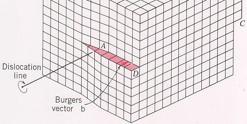
12 The Bugers Vector: b Dislocation is a lattice line defect that defines the boundary between slipped & unslipped part of a crystal. b characterizes the magnitude & direction of a given dislocation. Determination: 1. Choose, arbitrarily, a positive direction. 2. Draw a counterclockwise (RHS) circuit of atom-toatom steps. 3. Vector b connecting the end point to the starting point is Burgers vector of the dislocation.
13 Assume that the direction out of paper plane is +ve. Draw a circuit in the same manner as a rotating righthand screw screw advancing in the positive direction.


14 Assume that the right to left direction is +ve. Draw a circuit in the same manner as a rotating righthand screw screw advancing in the positive direction.
15 FS/RH Burgers Circuit Dislocation line going into the board
16
17 The Burgers vector is given by the line integral, taken in the RHS relative to (the dislocation line direction), of the elastic displacement u around the dislocation b u dl l C Dislocation is characterized by two parameters, b and
18 Differences Edge dislocation 1. Dislocation line lies perpendicular to b b. =0 2. Moves in the b direction. Screw Dislocation 1. Dislocation line lies parallel to b b. =b (+ for RH screw and for LH screw) 2. Moves perpendicular to the b direction.
19 Mixed Dislocations b is invariant along the dislocation line b s ( b ξ)ξ b e ξ (bξ)
20 A dislocation whose Burgers vector is a lattice translation vector is known as a Perfect or unit dislocation. The dislocation density, r, is defined as the total length of dislocation line per unit volume of crystal. (Units = 1/mm 2 ) Or, no. of dislocations intersecting a unit area. Well-annealed crystals, r ~ 10 4 to 10 5 /cm 2 Heavily cold-worked metal, r ~10 11 /cm 2
21 Important Points Slip plane is the plane that contains both and b For an edge dislocation, since and b are perpendicular to each other, the slip plane is uniquely defined. Can t cross-slip! Need nonconservative (climb) motion For a screw dislocation, the slip plane can be any plane containing the dislocation. Can glide in any direction that is parallel to the original orientation.


22 Cross-Slip
23 Dislocation Loops Dislocations can terminate at a free surface or a grain boundary, but never within a grain. Dislocations must form network with branches terminating at the surface or must form loops.
24 At Nodes, b 1 +b 2 +b 3 = 0 n i1 b i 0 If dislocations are of the same sense, b 1 = b 2 +b 3
25 Elastic Properties of Dislocations Screw Dislocation Shear strain, g Z = b/2r Shear stress, t Z = mb/2r Only applicable for r > 5-10Å
26 Edge Dislocation
27 xx yy by 2(1 ) by 2(1 ) Edge Dislocation (3x 2 y 2 ) (x 2 y 2 ) 2 (x 2 y 2 ) (x 2 y 2 ) 2 bx (x 2 y 2 ) xy yx 2(1 ) (x 2 y 2 ) 2 zz ( xx yy ) xz zx zy yz 0 p xx 1 yy zz b 2 (1 ) x 2 y y 2
28 Energy of Dislocations E screw 1 2 r r 1 0 z bdr E 1 screw 2 r 1 b2 dr b 2 ln r 1 r 0 2 r 4 ln r 0 E edge b ln r 1 r 0 Mixed dislocations, E b 2 a=0.5-1
29 E el (edge) > E el (screw) by 1/(1-n) E el ~4 nj/m or 1 aj (6 ev) for each atom plane threaded by the dislocation E core ~ aj Varies as the dislocation moves Crystals contain many dislocations Crystals contain many dislocations Dislocations tend to form configurations in which the superimposed long range stress fields cancel out R~half of the average spacing for dislocations arranged in random
30 Consequences of Eb 2 Minimize b, hence slip occurs usually in close-packed directions! Dislocation dissociation when b 1 2 b 2 2 b 3 2 Known as Frank s Rule
31 Line Tension, T (energy per unit length) is increase in energy per unit increase in the dislocation line length T b 2 Tries to straighten the dislocation, so as to minimize the energy Stress required to keep a dislocation curved, t T/bR mb/r R-radius of curvature Glide force acting on a dislocation, f, due to applied shear stress, t f (/unit length) = tb
32 Stress on a Curved Dislocation Net force acts in OA direction Disln. will remain curved if there is a stress t o opposing it d =dl/r Outward force = t o b dl Inward force = 2T sin (d/2) =T d for small d Equilibrium, t o b dl =T d T= agb 2 t o = a G b/r
33 Glide force acting on a dislocation Derivation: Use PVW Work done = (t x area) x b = t l 1 l 2 b (1) Works against force, f, opposing against its motion = (f l 1 )l 2 Note that f defined as force per unit length Equating f = t b
34 Forces between Dislocations
35 Forces between Dislocations Screw dislocations of opposite sign attract and those of the same sign repel. The magnitude of the attractive/repulsive force is inversely proportional to the distance between them. Edge dislocations: Dislocations on the same slip plane, attract each other if they are of opposite signs and repel if of the same sign. Complicated if they are on different planes
36 Dislocations of same sign, but on parallel slip planes, attract each other if x<y Can form arrays with dislocations stacked one the other to form Low-angle tilt boundaries.
37 Stable Configurations
38 Small Angle Grain Boundary
39 Image Forces A dislocation near the surface is attracted towards the free surface. (Repelled by a rigid surface layer.) Analysis for a infinite, straight dislocation line that is parallel to the surface at x = d.
40 For a free surface, tractions s xx, s yx, and s xz should be zero at x = 0. Met if a opposite sign (imaginary) dislocation exists at x = -d. For screw dislocation, at x> ) ( 1 ) ( 1 2 y d x y d x Gby zx ) ( ) ( ) ( ) ( 2 y d x d x y d x d x Gb zy
41 Force per unit length in x direction, F x, induced by the surface is obtained by F x For an edge dislocation, zy b xd, y0 2 Gb 4d Gb F x 4 (1 ) d Image forces decrease with increasing d. May remove dislocations from surface. Important factor in TEM of dislocations and in thin films! 2
42 Partial Dislocations As noted earlier, a dislocation can dissociate to minimize energy. Has to satisfy, b 12 > b 22 +b 3 2 Dislocations b 2 and b 3 are known as Shockley partial dislocations. In FCC, <110> type dislocation dissociates into two <112> type dislocation a 2 a a 6
43
44 In HCP, Partials repel each other! The equilibrium separation distance depends on the stacking fault energy (SFE)! Aside FCC crystal structure is created by stacking (111) planes in ABCABCAB..manner HCP by stacking in ABABABAB.. manner 3 1 3


45


46 HCP FCC


47 Extended Dislocations Stacking sequence, ABCACABCA
48 Stacking Fault A 2-D defect Has surface energy, g. Small compared to GB energy. SFE and the repulsive force between the partials determine the equilibrium separation distance, d, between two partial dislocations. ( b 2 b3) d 2 High SFE, low width and vice-versa
49 SFE depends on material, composition, etc.. SFE determines the ability of dislocations to cross-slip and in-turn work hardening characteristics. High SFE, lower separation between partials, easier cross-slip, lower work hardening exponent, n. Materials exhibit wavy slip. Low SFE, higher separation between partials, difficult for cross-slip, and higher n. Material exhibits planar slip.
50
51 SFE and Slip Character Metal SFE (mj/m 2 ) n Slip Character Stainless <10 ~0.45 Planar Steel Cu ~90 ~0.3 Planar/ Wavy Al ~ Wavy
52 Lomer-Cottrell Lock A sessile dislocation that occurs in FCC metals. Also known as Stair-Rod Dislocations
53 Cottrell Lock in BCC Metals Two perfect dislocations interact to form a sessile [100] type dislocation. a 0 a a The [001] dislocation lies on a {001} plane and large stresses are required to move it. Helps in Cleavage fracture through crack nucleation. (Acts as a microcrack.)
54 Superlattice Dislocations Found in Intermetallic compounds Superlattic = long range order
55 (111)

 The region")
56 Movement of one dislocation generates unfavorable lattice distortion. Creates a antiphase domain. Need another dislocation to close the antiphase domain. Dislocations have to move in pairs (superdislocation) The region (2D) between them in known as Antiphase boundary (APB)
57 APB is a 2-D defect. APB width depends on the balance between the APB energy and the repulsive force between dislocations. APB energy depends on the degree of order in the lattice. APBs lead to planar slip character. In some precipitation hardened alloys such as Al-Li alloys, the ordered precipitates force planar slip, and hence lowered ductility.
58 Kinks Dislocation step in the slip plane Kink in an edge dislocation has screw character Kink in a screw dislocation has edge character Easy to remove
59 Jogs Steps in dislocation normal to the slip plane Jogs always have an edge character
60 Dislocation-Dislocation Intersection Summary When two edge dislns. interact jogs are created. These jogs do not impede the dislocation motion.
61 A screw disln. interacts with another screw or edge disln. to produce edge jogs that impede the motion.
62 Nonconservative motion of jogs is required to move jagged screw dislocations.
63 0 x b 2 b 2 x 0 x 0
64 Disregistry of atoms Defined as displacement difference Du between two atoms on adjacent sites above and below the slip plane Du = u(b) u(a) Width, w, of a dislocation is defined as the distance over which Du is one half of its max value, i.e. b/4 Du b/4 A measure of the size of the dislocation core wherein the elasticity theory fails
65 f(x) = d(du)/dx Distribution of Burgers Vector Core width, b-5b, depends on interatomic potential and crystal structure
66 The Peierls Barrier The core disregistry imparts resistance to dislocation motion. Peierls (1940) and Nabarro (1947) assumed a sisusoidal force relations to obtain analytical solutions for Du. P-N calculated the dislocation energy per unit length as a function of the dislocation Position. 2 Max. fluctuation, Gb 2w E P N exp( (1 ) Max. slope of E p is critical force per unit length required to move the dislocation. b )
67 The Peierls-Nabarro Stress, t P-N The t P-N characterizes the lattice s resistance to dislocation motion from one low energy position to another. Magnitude depends on 1) The width, W, of the dislocation. W represents the distance over which the lattice is distorted. 2) Distance between similar planes, a.
68 t P-N m exp(-2w/b) W = a/(1-) t P-N decreases with increasing a. Close packed planes preferred.
69 W depends on atomic structure and atomic bonding (spherical vs. directional). Close packed structures (spherical), W is high, and hence t P-N is low. When bonding forces are highly directional (BCC, ionic and covalent bonded materials), W is low, and hence t P-N is large. The t P-N is sensitive to thermal energy in the lattice and, hence, to the test temperature. Low T, High t P-N. Increase in T, t P-N decreases.
70 W and Temperature Sensitivity Material Crystal Type W Peierls Stress y temp. Sensitivity Metal FCC Wide Very Small Metal BCC Narrow Moderate Strong Ceramic Ionic Narrow Large Strong P (xg) Negligible < Ceramic Covalent Very Narrow Very Large Strong 10-2
 sheared by N dislns.")
71 Deformation due to Dislocation Motion (Orowan s equation) Deformation is related to no. of dislns that move and the distance traveled by them. Cube (dx 1, dx 2, dx 3 ) sheared by N dislns. Plastic strain, g 13 =Nb/dx 3 Density of dislocations, r=ndx 2 / dx 1 dx 2 dx 3 g 13 =rbdx 1
72 In real materials, deformation generated by each dislocation is related to the average distance traveled, l, by it. bl 13 Correction parameter, k, to account for multiple slip, misalignment, etc. kbl p Known as Taylor-Orowan or Orowan s eqn. Note: r mobile < r total As r increases, more and more dislocations are locked. Taking the time derivative, d dt p kb dl dt or p kb
73 Origin of Dislocations Thermodynamically stable density of dislocations is zero in a stress-free crystal Dislocations in freshly grown crystals are due to 1) dislns. in seed crystals 2) Nucleation during the growth process a) heterogeneous nucleation due to internal stresses thermal gradients, change in composition, or change in lattice structure b) impingement of growing interfaces c) formation and movement of disln. loops formed by the vacancy platelets
74 Dislocation Multiplication Dislocation density increases by 6 to 8 orders of magnitude when a fully annealed metal is coldworked heavily. Explained by dislocation multiplication mechanisms. Most common is the Frank-Read source-- A dislocation segment pinned on either end. Shear stress will cause the dislocation to bow out. Radius, R Gb/t When R = l/2, the loop becomes unstable
75 Frank-Read Source

76


77 Frank-Read Source in a Si Crystal
78 Cross-slip is another Mechanism for Dislocation multiplication
79 Slip and Twinning

80
81 HCP If c/a < 1.633, then True in Zr(1.593) and Ti(1.587). Can t explain in Co (1.623), Mg (1.623), & Be (1.568). If c/a > 1.633, then basal slip plane {0001}. Examples: Zn (1.856) and Cd (1.886).
82 Von Mises Criterion Ductility of a material depends on its ability to withstand a general homogeneous strain involving an arbitrary shape change Von Mises postulated that the above is possible when there are 5 independent slip systems. Six independent components of strain tensor, e xx, e yy, e zz, e xy, e xz, and e zy But, e xx +e yy +e zz = 0 (constant vol. process) Hence, 5 independent slip systems.
83 Independent Slip System Defined as one producing crystal shape change that can t be reproduced by any other slip system. Taylor (1938): Of the 12 possible slip systems in FCC and BCC, 5 are independent. Hence, BCC and FCC metals show good ductility. For HCP, only two out of three (basal or prism) slip systems are independent. Hence, HCP metals lack ductility and need twinning.
84 Geometry of Slip Single crystal subjected to stress. A slip-plane =A 0 /cos P resolved = Pcosl Resolved shear stress, t rss = (P/A 0 ) coscosl Plastic deformation starts when slip gets activated, i.e., t rss = t crss Critical RSS The product coscosl is known as Schmid factor
85 Yield Behavior of Anthracene Crystals
86 Slip Plane Rotation L L i 0 sin 0 sin i L i, L o -gage lengths before and after plastic flow
87 Stereographic Projection
88 Standard Projection for Cubic Crystals
89 The relative orientation of a crystal can be given with respect to any triangle within the stereographic projection.
90 Primary slip system (slip system with highest Schmid factor) : Rotation occurs along great circle, towards 101 pole. As the crystal rotates, l decreases and increases If, l 0 >45º> 0, rotation will increase the Schmid factor. Yielding at lower loads. Geometric Softening. If, l 0 <45º< 0, Geometric Hardening. (Different from work hardening, which is a result of dislocation-dislocation interactions.)
91
92 When the crystal axis crosses over into the triangle II, slip system (conjugate slip system) becomes activated. Now, the crystal starts rotating towards [011] Back and forth movement of crystal orientation between primary and conjugate slip systems, moves it along the [001] tie line until load axis is parallel to Cross-slip Slip system: Critical Slip System:
93 Resolved shear stress vs. shear strain response of a FCC crystal oriented for single slip I: Easy glide (primary slip) II: Linear hardening (secondary slip) III: Parabolic hardening (dynamic recovery & Cross-slip) cos 1 cos 0 l sin l 2 1 / l / l 0 2 sin 2 0 cos 0 Suresh: p. 31


94 Twinning
95
96 Differences between Slip & Twinning Slip Simple translation of one rigid portion over the other. No shape change or orientation change. Multiples of unit displacement, b. 1-D defect Twinning A shape change is involved with parts oriented differently Atom movements on all planes in fractional amounts, with d distance from the twin boundary. A 2-D defect
97 Mechanical (or deformation) twins: A result of superimposed plastic deformation. ex: Zn Annealing Twins: A result of pre-existing plastic deformation. Example: Brass -Form during recrystallization and grain growth of heavily deformed materials. -Form due to interaction of new grains with stacking faults. -Generally observed in low SFE metals (high stacking fault probability). -Increase with increased cold work.
98
99
100 Twin Geometry X, Y, Z to X, Y, Z X= X, Z=Z, Y= Y+SZ where S is the shear strain. Equation for the distorted sphere: X 2 +Y 2 +Z 2 =1 X 2 +Y 2 +2SZY+Z 2 (1+S 2 ) =1 Ellipsoid with major axis inclined to 1 by. AO is shortened and BO is elongated. Compositional plane (K 1 ) and plane OC (K 2 ) are undistorted.
101 S = 2cot2f
102 Elongation Potential of Twinning Total deformation to be expected from a completely twinned crystal is l l 4 1 S S S where S is the shear strain. Quite small in HCP crystals. However, the rotation of the crystal within the twins may make them favorable for slip deformation.
103 Twin Shape b increases with decreasing shear strain (Cahn 1954) Twin initiation stress is much larger than that required to propagate it.
![Twinning in HCP Crystals 2+2 =180 cot2 =S/2 S=(tan 2-1)/tan tan =c/3a S [( c / a) 2 3)] 3a 3c](/docs-images/81/83419270/images/104-0.jpg "c/a = 3, twinning does not occur in {1012} mode Twin deformation is opposite in sense for c/a")
104 Twinning in HCP Crystals 2+2 =180 cot2 =S/2 S=(tan 2-1)/tan tan =c/3a S [( c / a) 2 3)] 3a 3c c/a = 3, twinning does not occur in {1012} mode Twin deformation is opposite in sense for c/a >< 3
105 Be (c/a=1.568) Compression of basal plane and tension of the prism plane. If basal plane is oriented parallel to the loading direction, twinning will only occur under compression
106 Zn (c/a = 1.856) Zn will twin when applied stress causes tension in basal plane or compression in prism.
107 c/a=1.856 c/a=1.624
108 c/a <3 = 3 >3
109 Commonality between Martensite and Twinning Both form as a result of atoms in a finite parent phase crystal realigning as new crystal lattices. In twins, the realignment reproduces the original crystal structure with a new orientation. In martensite, new orientation as well as new crystal structure (e.g. FCC to BCT in Steels.) In both cases, the change in shape distorts the surrounding matrix. Both look alike, either small lenses or plates. Driving force: Applied shear stress for twins Free energy Change for Martensite


110 Deformation twins in Polycrystalline Zr. Martensite plates in a Fe-1.5C-5.1Ni steel
Chapter Outline Dislocations and Strengthening Mechanisms. Introduction
 Chapter Outline Dislocations and Strengthening Mechanisms What is happening in material during plastic deformation? Dislocations and Plastic Deformation Motion of dislocations in response to stress Slip
Strengthening Mechanisms
 ME 254: Materials Engineering Chapter 7: Dislocations and Strengthening Mechanisms 1 st Semester 1435-1436 (Fall 2014) Dr. Hamad F. Alharbi, harbihf@ksu.edu.sa November 18, 2014 Outline DISLOCATIONS AND
Chapter 7 Dislocations and Strengthening Mechanisms. Dr. Feras Fraige
 Chapter 7 Dislocations and Strengthening Mechanisms Dr. Feras Fraige Chapter Outline Dislocations and Strengthening Mechanisms What is happening in material during plastic deformation? Dislocations and
Movement of edge and screw dislocations
 Movement of edge and screw dislocations Formation of a step on the surface of a crystal by motion of (a) n edge dislocation: the dislocation line moves in the direction of the applied shear stress τ. (b)
Chapter 8. Deformation and Strengthening Mechanisms
 Chapter 8 Deformation and Strengthening Mechanisms Chapter 8 Deformation Deformation and Strengthening Issues to Address... Why are dislocations observed primarily in metals and alloys? How are strength
Fundamentals of Plastic Deformation of Metals
 We have finished chapters 1 5 of Callister s book. Now we will discuss chapter 10 of Callister s book Fundamentals of Plastic Deformation of Metals Chapter 10 of Callister s book 1 Elastic Deformation
Dislocations in Materials. Dislocations in Materials
 Pose the following case scenario: Consider a block of crystalline material on which forces are applied. Top Force (111) parallel with top surface Bottom Force Sum Sum of of the the applied forces give
Single vs Polycrystals
 WEEK FIVE This week, we will Learn theoretical strength of single crystals Learn metallic crystal structures Learn critical resolved shear stress Slip by dislocation movement Single vs Polycrystals Polycrystals
Lecture # 11 References:
 Lecture # 11 - Line defects (1-D) / Dislocations - Planer defects (2D) - Volume Defects - Burgers vector - Slip - Slip Systems in FCC crystals - Slip systems in HCP - Slip systems in BCC Dr.Haydar Al-Ethari
Twins & Dislocations in HCP Textbook & Paper Reviews. Cindy Smith
 Twins & Dislocations in HCP Textbook & Paper Reviews Cindy Smith Motivation Review: Outline Crystal lattices (fcc, bcc, hcp) Fcc vs. hcp stacking sequences Cubic {hkl} naming Hcp {hkil} naming Twinning
3, MSE 791 Mechanical Properties of Nanostructured Materials
 3, MSE 791 Mechanical Properties of Nanostructured Materials Module 3: Fundamental Physics and Materials Design Lecture 1 1. What is strain (work) hardening? What is the mechanism for strain hardening?
IMPERFECTIONSFOR BENEFIT. Sub-topics. Point defects Linear defects dislocations Plastic deformation through dislocations motion Surface
 IMPERFECTIONSFOR BENEFIT Sub-topics 1 Point defects Linear defects dislocations Plastic deformation through dislocations motion Surface IDEAL STRENGTH Ideally, the strength of a material is the force necessary
Module-6. Dislocations and Strengthening Mechanisms
 Module-6 Dislocations and Strengthening Mechanisms Contents 1) Dislocations & Plastic deformation and Mechanisms of plastic deformation in metals 2) Strengthening mechanisms in metals 3) Recovery, Recrystallization
Lecture # 11. Line defects (1D) / Dislocations
 / Dislocations") Lecture # 11 - Line defects (1-D) / Dislocations - Planer defects (2D) - Volume Defects - Burgers vector - Slip - Slip Systems in FCC crystals - Slip systems in HCP - Slip systems in BCC References: 1-
Lecture # 11 - Line defects (1-D) / Dislocations - Planer defects (2D) - Volume Defects - Burgers vector - Slip - Slip Systems in FCC crystals - Slip systems in HCP - Slip systems in BCC References: 1-
(a) Would you expect the element P to be a donor or an acceptor defect in Si?
 Would you expect the element P to be a donor or an acceptor defect in Si?") MSE 200A Survey of Materials Science Fall, 2008 Problem Set No. 2 Problem 1: At high temperature Fe has the fcc structure (called austenite or γ-iron). Would you expect to find C atoms in the octahedral
MSE 200A Survey of Materials Science Fall, 2008 Problem Set No. 2 Problem 1: At high temperature Fe has the fcc structure (called austenite or γ-iron). Would you expect to find C atoms in the octahedral
DISLOCATIONS. Edge dislocation Screw dislocation Dislocations in crystals
 Edge dislocation Screw dislocation Dislocations in crystals Further reading DISLOCATIONS Part of Introduction to Dislocations D. Hull and D.J. Bacon Pergamon Press, Oxford (1984) Advanced reading (comprehensive)
Chapter 8 Strain Hardening and Annealing
 Chapter 8 Strain Hardening and Annealing This is a further application of our knowledge of plastic deformation and is an introduction to heat treatment. Part of this lecture is covered by Chapter 4 of
Introduction to Engineering Materials ENGR2000 Chapter 7: Dislocations and Strengthening Mechanisms. Dr. Coates
 Introduction to Engineering Materials ENGR2000 Chapter 7: Dislocations and Strengthening Mechanisms Dr. Coates An edge dislocation moves in response to an applied shear stress dislocation motion 7.1 Introduction
3. Anisotropic blurring by dislocations
 Dynamical Simulation of EBSD Patterns of Imperfect Crystals 1 G. Nolze 1, A. Winkelmann 2 1 Federal Institute for Materials Research and Testing (BAM), Berlin, Germany 2 Max-Planck- Institute of Microstructure
Single Crystal Deformation
 Single Crystal Deformation To make the connection between dislocation behavior and yield strength as measured in tension, consider the deformation of a single crystal. Given an orientation for single slip,
Chapter 7: Dislocations and strengthening mechanisms
 Chapter 7: Dislocations and strengthening mechanisms Introduction Basic concepts Characteristics of dislocations Slip systems Slip in single crystals Plastic deformation of polycrystalline materials Plastically
Lectures on: Introduction to and fundamentals of discrete dislocations and dislocation dynamics. Theoretical concepts and computational methods
 Lectures on: Introduction to and fundamentals of discrete dislocations and dislocation dynamics. Theoretical concepts and computational methods Hussein M. Zbib School of Mechanical and Materials Engineering
Imperfections in atomic arrangements
 MME131: Lecture 9 Imperfections in atomic arrangements Part 2: 1D 3D Defects A. K. M. B. Rashid Professor, Department of MME BUET, Dhaka Today s Topics Classifications and characteristics of 1D 3D defects
TOPIC 2. STRUCTURE OF MATERIALS III
 Universidad Carlos III de Madrid www.uc3m.es MATERIALS SCIENCE AND ENGINEERING TOPIC 2. STRUCTURE OF MATERIALS III Topic 2.3: Crystalline defects. Solid solutions. 1 PERFECT AND IMPERFECT CRYSTALS Perfect
a. 50% fine pearlite, 12.5% bainite, 37.5% martensite. 590 C for 5 seconds, 350 C for 50 seconds, cool to room temperature.
 Final Exam Wednesday, March 21, noon to 3:00 pm (160 points total) 1. TTT Diagrams A U.S. steel producer has four quench baths, used to quench plates of eutectoid steel to 700 C, 590 C, 350 C, and 22 C
STRENGTHENING MECHANISM IN METALS
 Background Knowledge Yield Strength STRENGTHENING MECHANISM IN METALS Metals yield when dislocations start to move (slip). Yield means permanently change shape. Slip Systems Slip plane: the plane on which
Planar Defects in Materials. Planar Defects in Materials
 Classification of Defects in Solids: Planar defects: Stacking faults o {311} defects in Si o Inversion domain boundaries o Antiphase boundaries (e.g., super dislocations): analogous to partials but in
Metal working: Deformation processing II. Metal working: Deformation processing II
 Module 28 Metal working: Deformation processing II Lecture 28 Metal working: Deformation processing II 1 Keywords : Difference between cold & hot working, effect of macroscopic variables on deformation
ECE236A Semiconductor Heterostructure Materials Defects in Semiconductor Crystals Lecture 6 Oct. 19, 2017
 ECE236A Semiconductor Heterostructure Materials Defects in Semiconductor Crystals Lecture 6 Oct. 19, 2017 Stacking sequence in simple crystals. Stacking faults (intrinsic, extrinsic) Twin boundaries Dislocations
Problems to the lecture Physical Metallurgy ( Materialkunde ) Chapter 6: Mechanical Properties
 Chapter 6: Mechanical Properties") Institut für Metallkunde und Metallphysik Direktor: Prof. Dr. rer. nat. Günter Gottstein RWTH Aachen, D-52056 Aachen Internet: http://www.imm.rwth-aachen.de E-mail: imm@imm.rwth-aachen.de Tel.: +49 241
Institut für Metallkunde und Metallphysik Direktor: Prof. Dr. rer. nat. Günter Gottstein RWTH Aachen, D-52056 Aachen Internet: http://www.imm.rwth-aachen.de E-mail: imm@imm.rwth-aachen.de Tel.: +49 241
Chapter 4. Introduction to Dislocations
 Chapter 4 Introduction to Dislocations The discrepancy between the theoretical and observed yield stresses of crystals Dislocations The Burgers vector Vector notation for dislocations Dislocations in the
E45 Midterm 01 Fall 2007! By the 0.2% offset method (shown on plot), YS = 500 MPa
, YS = 500 MPa") 1.!Mechanical Properties (20 points) Refer to the following stress-strain plot derived from a standard uniaxial tensile test of a high performance titanium alloy to answer the following questions. Show
1.!Mechanical Properties (20 points) Refer to the following stress-strain plot derived from a standard uniaxial tensile test of a high performance titanium alloy to answer the following questions. Show
3.22 Mechanical Behavior of materials PS8 Solution Due: April, 27, 2004 (Tuesday) before class (10:00am)
 before class (10:00am)") 3. Mechanical Behavior of materials PS8 Solution Due: April, 7, 004 (Tuesday before class (10:00am 8 1. Annealed copper have a dislocation density of approimately 10 cm. Calculate the total elastic strain
3. Mechanical Behavior of materials PS8 Solution Due: April, 7, 004 (Tuesday before class (10:00am 8 1. Annealed copper have a dislocation density of approimately 10 cm. Calculate the total elastic strain
Learning Objectives. Chapter Outline. Solidification of Metals. Solidification of Metals
 Learning Objectives Study the principles of solidification as they apply to pure metals. Examine the mechanisms by which solidification occurs. - Chapter Outline Importance of Solidification Nucleation
Dislocations & Materials Classes. Dislocation Motion. Dislocation Motion. Lectures 9 and 10
 Lectures 9 and 10 Chapter 7: Dislocations & Strengthening Mechanisms Dislocations & Materials Classes Metals: Disl. motion easier. -non-directional bonding -close-packed directions for slip. electron cloud
Dept.of BME Materials Science Dr.Jenan S.Kashan 1st semester 2nd level. Imperfections in Solids
 Why are defects important? Imperfections in Solids Defects have a profound impact on the various properties of materials: Production of advanced semiconductor devices require not only a rather perfect
Imperfections, Defects and Diffusion
 Imperfections, Defects and Diffusion Lattice Defects Week5 Material Sciences and Engineering MatE271 1 Goals for the Unit I. Recognize various imperfections in crystals (Chapter 4) - Point imperfections
Strengthening Mechanisms
 Strengthening Mechanisms The ability of a metal/ alloy to plastically deform depends on the ability of dislocations to move. Strengthening techniques rely on restricting dislocation motion to render a
Defects and Diffusion
 Defects and Diffusion Goals for the Unit Recognize various imperfections in crystals Point imperfections Impurities Line, surface and bulk imperfections Define various diffusion mechanisms Identify factors
ME 254 MATERIALS ENGINEERING 1 st Semester 1431/ rd Mid-Term Exam (1 hr)
") 1 st Semester 1431/1432 3 rd Mid-Term Exam (1 hr) Question 1 a) Answer the following: 1. Do all metals have the same slip system? Why or why not? 2. For each of edge, screw and mixed dislocations, cite
1 st Semester 1431/1432 3 rd Mid-Term Exam (1 hr) Question 1 a) Answer the following: 1. Do all metals have the same slip system? Why or why not? 2. For each of edge, screw and mixed dislocations, cite
- Slip by dislocation movement - Deformation produced by motion of dislocations (Orowan s Eq.)
") Lecture #12 - Critical resolved shear stress Dr. Haydar Al-Ethari - Slip y dislocation movement - Deformation produced y motion of dislocations (Orowan s Eq.) References: 1- Derek Hull, David Bacon, (2001),
Lecture #12 - Critical resolved shear stress Dr. Haydar Al-Ethari - Slip y dislocation movement - Deformation produced y motion of dislocations (Orowan s Eq.) References: 1- Derek Hull, David Bacon, (2001),
The Dislocation Basis of Yield and Creep
 The Dislocation Basis of Yield and Creep David Roylance Department of Materials Science and Engineering Massachusetts Institute of Technology Cambridge, MA 02139 March 22, 2001 Introduction Phenomenological
Activation of deformation mechanism
 Activation of deformation mechanism The deformation mechanism activates when a critical amount of mechanical stress imposed to the crystal The dislocation glide through the slip systems when the required
Department of Materials Science and Engineering Massachusetts Institute of Technology 3.14 Physical Metallurgy Fall 2003 Exam I
 Department of Materials Science and Engineering Massachusetts Institute of Technology 3.14 Physical Metallurgy Fall 2003 Exam I 3 2.5 2 Frequency 1.5 1 0.5 0 10 11 12 13 14 15 16 17 18 19 20 21 22 23 24
Material Science. Prof. Satish V. Kailas Associate Professor Dept. of Mechanical Engineering, Indian Institute of Science, Bangalore India
 Material Science Prof. Satish V. Kailas Associate Professor Dept. of Mechanical Engineering, Indian Institute of Science, Bangalore 560012 India Chapter 3. Imperfections in Solids Learning objectives:
Chapter 7: Dislocations and strengthening mechanisms. Strengthening by grain size reduction
 Chapter 7: Dislocations and strengthening mechanisms Mechanisms of strengthening in metals Strengthening by grain size reduction Solid-solution strengthening Strain hardening Recovery, recrystallization,
Stress Fields Around Dislocations
 Stress Fields Around Dislocations The crystal lattice in the vicinity of a dislocation is distorted (or strained). The stresses that accompanied the strains can e calculated y elasticity theory eginning
Lectures on: Introduction to and fundamentals of discrete dislocations and dislocation dynamics. Theoretical concepts and computational methods
 Lectures on: Introduction to and fundamentals of discrete dislocations and dislocation dynamics. Theoretical concepts and computational methods Hussein M. Zi School of Mechanical and Materials Engineering
Materials Science. Imperfections in Solids CHAPTER 5: IMPERFECTIONS IN SOLIDS. Types of Imperfections
 In the Name of God Materials Science CHAPTER 5: IMPERFECTIONS IN SOLIDS ISSUES TO ADDRESS... What are the solidification mechanisms? What types of defects arise in solids? Can the number and type of defects
Introduction to Engineering Materials ENGR2000 Chapter 4: Imperfections in Solids. Dr. Coates
 Introduction to Engineering Materials ENGR000 Chapter 4: Imperfections in Solids Dr. Coates Learning Objectives 1. Describe both vacancy and self interstitial defects. Calculate the equilibrium number
MT 348 Outline No MECHANICAL PROPERTIES
 MT 348 Outline No. 1 2009 MECHANICAL PROPERTIES I. Introduction A. Stresses and Strains, Normal and Shear Loading B. Elastic Behavior II. Stresses and Metal Failure A. ʺPrincipal Stressʺ Concept B. Plastic
Dislocations and Plastic Deformation
 Dislocations and Plastic Deformation Edge and screw are the two fundamental dislocation types. In an edge dislocation, localized lattice distortion exists along the end of an extra half-plane of atoms,
Chap. 7. Intersection of Dislocations
 Chap. 7. Intersection of Dislocations Plastic Deformation of Crystal - Slip starts at a slip system having the largest Schmid factor. - A dislocation moving in slip plane will intersect other dislocations
CME 300 Properties of Materials. ANSWERS Homework 2 September 28, 2011
 CME 300 Properties of Materials ANSWERS Homework 2 September 28, 2011 1) Explain why metals are ductile and ceramics are brittle. Why are FCC metals ductile, HCP metals brittle and BCC metals tough? Planes
Mechanical Properties
 Mechanical Properties Elastic deformation Plastic deformation Fracture II. Stable Plastic Deformation S s y For a typical ductile metal: I. Elastic deformation II. Stable plastic deformation III. Unstable
Crystal Defects. Perfect crystal - every atom of the same type in the correct equilibrium position (does not exist at T > 0 K)
") Crystal Defects Perfect crystal - every atom of the same type in the correct equilibrium position (does not exist at T > 0 K) Real crystal - all crystals have some imperfections - defects, most atoms are
Crystal Defects Perfect crystal - every atom of the same type in the correct equilibrium position (does not exist at T > 0 K) Real crystal - all crystals have some imperfections - defects, most atoms are
Point Defects. Vacancies are the most important form. Vacancies Self-interstitials
 Grain Boundaries 1 Point Defects 2 Point Defects A Point Defect is a crystalline defect associated with one or, at most, several atomic sites. These are defects at a single atom position. Vacancies Self-interstitials
Chapter 2: Mechanical Behavior of Materials
 Chapter : Mechanical Behavior of Materials Definition Mechanical behavior of a material relationship - its response (deformation) to an applied load or force Examples: strength, hardness, ductility, stiffness
CHAPTER 8 DEFORMATION AND STRENGTHENING MECHANISMS PROBLEM SOLUTIONS
 CHAPTER 8 DEFORMATION AND STRENGTHENING MECHANISMS PROBLEM SOLUTIONS Slip Systems 8.3 (a) Compare planar densities (Section 3.15 and Problem W3.46 [which appears on the book s Web site]) for the (100),
Engineering materials
 1 Engineering materials Lecture 2 Imperfections and defects Response of materials to stress 2 Crystalline Imperfections (4.4) No crystal is perfect. Imperfections affect mechanical properties, chemical
Materials and their structures
 Materials and their structures 2.1 Introduction: The ability of materials to undergo forming by different techniques is dependent on their structure and properties. Behavior of materials depends on their
Why are dislocations observed primarily in metals CHAPTER 8: DEFORMATION AND STRENGTHENING MECHANISMS
 Why are dislocations observed primarily in metals CHAPTER 8: and alloys? DEFORMATION AND STRENGTHENING MECHANISMS How are strength and dislocation motion related? How do we manipulate properties? Strengthening
Defect in crystals. Primer in Materials Science Spring
 Defect in crystals Primer in Materials Science Spring 2017 11.05.2017 1 Introduction The arrangement of the atoms in all materials contains imperfections which have profound effect on the behavior of the
Chapter 8: Deformation & Strengthening Mechanisms. School of Mechanical Engineering Choi, Hae-Jin ISSUES TO ADDRESS
 Chapter 8: Deformation & Strengthening Mechanisms School of Mechanical Engineering Choi, Hae-Jin Materials Science - Prof. Choi, Hae-Jin Chapter 8-1 ISSUES TO ADDRESS Why are the number of dislocations
Recrystallization textures in metals and alloys
 Recrystallization textures in metals and alloys Uniaxial deformation Aluminium wire F.C.C. Metals and alloys FCC wires retain deformation texture ([111]+[100]) upon recrystallisation Composition / Purity
Introduction to Materials Science
 EPMA Powder Metallurgy Summer School 27 June 1 July 2016 Valencia, Spain Introduction to Materials Science Prof. Alberto Molinari University of Trento, Italy Some of the figures used in this presentation
Chapter 9: Dislocations & Strengthening Mechanisms. Why are the number of dislocations present greatest in metals?
 Chapter 9: Dislocations & Strengthening Mechanisms ISSUES TO ADDRESS... Why are the number of dislocations present greatest in metals? How are strength and dislocation motion related? Why does heating
 Defects in solids http://www.bath.ac.uk/podcast/powerpoint/inaugural_lecture_250407.pdf http://www.materials.ac.uk/elearning/matter/crystallography/indexingdirectionsandplanes/indexing-of-hexagonal-systems.html
High temperature applications
 3. CREEP OF METALS Lecturer: Norhayati Ahmad High temperature applications -Steel power plants -Oil refineries -Chemical plants High operating temperatures Engine jet ----1400 o C Steam turbine power plants:
Engineering 45: Properties of Materials Final Exam May 9, 2012 Name: Student ID number:
 Engineering 45: Properties of Materials Final Exam May 9, 2012 Name: Student ID number: Instructions: Answer all questions and show your work. You will not receive partial credit unless you show your work.
Thermally Activated Mechanisms in Crystal Plasticity
 PERGAMON MATERIALS SERIES Thermally Activated Mechanisms in Crystal Plasticity by D. Caillard CEMES/CNRS-BP4347, F 31055 Toulouse Cedex J. L. Martin IPMC/EPFL-CH 1015 Lausanne 2003 PERGAMON An Imprint
Index. Cambridge University Press Introduction to Elasticity Theory for Crystal Defects R. W. Balluffi. Index.
 Airy stress functions formulation of 60 1 table of 426 alternator operator 419 Brown s formula 255 Burgers equation 264 5 Christoffel stiffness tensor 34 corresponding elastic fields 25 7 curvature tensor,
CHEM-E5225 :Electron Microscopy Imaging II
 CHEM-E5225 :Electron Microscopy Imaging II D.B. Williams, C.B. Carter, Transmission Electron Microscopy: A Textbook for Materials Science, Springer Science & Business Media, 2009. Z. Luo, A Practical Guide
ASE324: Aerospace Materials Laboratory
 ASE324: Aerospace Materials Laboratory Instructor: Rui Huang Dept of Aerospace Engineering and Engineering Mechanics The University of Texas at Austin Fall 2003 Lecture 3 September 4, 2003 Iron and Steels
Three stages: Annealing Textures. 1. Recovery 2. Recrystallisation most significant texture changes 3. Grain Growth
 Three stages: Annealing Textures 1. Recovery 2. Recrystallisation most significant texture changes 3. Grain Growth Cold worked 85% Cold worked 85% + stress relieved at 300 C for 1 hr Cold worked 85% +
4-Crystal Defects & Strengthening
 4-Crystal Defects & Strengthening A perfect crystal, with every atom of the same type in the correct position, does not exist. The crystalline defects are not always bad! Adding alloying elements to a
Department of Materials Science and Engineering Massachusetts Institute of Technology 3.14 Physical Metallurgy Fall Exam I
 Department of Materials Science and Engineering Massachusetts Institute of Technology 3.14 Physical Metallurgy Fall 2009 Exam I Monday, October 26, 2009 The Rules: 1) No calculators allowed 2) One hand
Imperfections in the Atomic and Ionic Arrangements
 Objectives Introduce the three basic types of imperfections: point defects, line defects (or dislocations), and surface defects. Explore the nature and effects of different types of defects. Outline Point
Module 10. Crystal Defects in Metals I. Lecture 10. Crystal Defects in Metals I
 Module 10 Crystal Defects in Metals I Lecture 10 Crystal Defects in Metals I 1 NPTEL Phase II : IIT Kharagpur : Prof. R. N. Ghosh, Dept of Metallurgical and Materials Engineering Introduction Keywords:
Introduction to Dislocation Mechanics
 Introduction to Dislocation Mechanics What is Dislocation Mechanics? (as meant here) The study of the stress state and deformation of continua whose elastic response is mediated by the nucleation, presence,
Atomistic Modeling of Thermally Activated Processes for Crystal Dislocations
 IPAM Workshop ELWS 2 UCLA, Oct 16-20, 2017 Atomistic Modeling of Thermally Activated Processes for Crystal Dislocations Oct 16, 2017 Wei Cai, Xiaohan Zhang, William Kuykendall* Department of Mechanical
Harper Dorn Creep. Chapter 4
 Chapter 4 Harper Dorn Creep Another mechanism for creep at high temperatures and low stresses was proposed in 1957 by Harper and Dorn [50] based on previous studies by Mott [295] and Weertman [189]. This
Tutorial 2 : Crystalline Solid, Solidification, Crystal Defect and Diffusion
 Tutorial 1 : Introduction and Atomic Bonding 1. Explain the difference between ionic and metallic bonding between atoms in engineering materials. 2. Show that the atomic packing factor for Face Centred
Strengthening Mechanisms. Today s Topics
 MME 131: Lecture 17 Strengthening Mechanisms Prof. A.K.M.B. Rashid Department of MME BUET, Dhaka Today s Topics Strengthening strategies: Grain strengthening Solid solution strengthening Work hardening
CHAPTER 4 INTRODUCTION TO DISLOCATIONS. 4.1 A single crystal of copper yields under a shear stress of about 0.62 MPa. The shear modulus of
 CHAPTER 4 INTRODUCTION TO DISLOCATIONS 4.1 A single crystal of copper yields under a shear stress of about 0.62 MPa. The shear modulus of copper is approximately. With this data, compute an approximate
Imperfections: Good or Bad? Structural imperfections (defects) Compositional imperfections (impurities)
 Compositional imperfections (impurities)") Imperfections: Good or Bad? Structural imperfections (defects) Compositional imperfections (impurities) 1 Structural Imperfections A perfect crystal has the lowest internal energy E Above absolute zero
Imperfections: Good or Bad? Structural imperfections (defects) Compositional imperfections (impurities) 1 Structural Imperfections A perfect crystal has the lowest internal energy E Above absolute zero
Mechanistic Models of Deformation Twinning and Martensitic Transformations. Bob Pond. Acknowledge: John Hirth
 Mechanistic Models of Deformation Twinning and Martensitic Transformations Bob Pond Acknowledge: John Hirth Classical Model (CM) Geometrical invariant plane Topological Model (TM) Mechanistic coherent
Fracture. Brittle vs. Ductile Fracture Ductile materials more plastic deformation and energy absorption (toughness) before fracture.
 before fracture.") 1- Fracture Fracture: Separation of a body into pieces due to stress, at temperatures below the melting point. Steps in fracture: 1-Crack formation 2-Crack propagation There are two modes of fracture depending
1- Fracture Fracture: Separation of a body into pieces due to stress, at temperatures below the melting point. Steps in fracture: 1-Crack formation 2-Crack propagation There are two modes of fracture depending
27-302, Microstructure & Properties II, A.D. Rollett. Fall Homework 4, due Monday, Nov. 25 th. Topic: properties dependent on precipitates
 27-302, Microstructure & Properties II, A.D. Rollett Fall 2002 Homework 4, due Monday, Nov. 25 th Topic: properties dependent on precipitates 1) Strengthening, Coarsening: [50 points] [This is essentially
Engineering Tripos Part IA Paper 2 - MATERIALS HANDOUT 4
 Engineering Tripos Part IA Paper 2 - MATERIALS HANDOUT 4 First Year 6. Microstructure of Engineering Materials II 6.1 Atomic basis of Plasticity in Crystalline Materials 6.2 Manipulating Properties II:
Chapter Outline: Failure
 Chapter Outline: Failure How do Materials Break? Ductile vs. brittle fracture Principles of fracture mechanics Stress concentration Impact fracture testing Fatigue (cyclic stresses) Cyclic stresses, the
Chapter 7: Plastic deformation, Strengthening and Recrystallisation of Metals
 Chapter 7: Plastic deformation, Strengthening and Recrystallisation of Metals What do I need to know? The Mechanism of Plastic formation in single and polycrystalline metals The slip mechanism The slip
Molecular Dynamics Investigation on the Fracture Behavior of Nanocrystalline Fe
 Molecular Dynamics Investigation on the Fracture Behavior of Nanocrystalline Fe Antoine N. Latapie Thesis submitted to the faculty of the Virginia Polytechnic Institute and State University In partial
CHAPTER 4 1/1/2016. Mechanical Properties of Metals - I. Processing of Metals - Casting. Hot Rolling of Steel. Casting (Cont..)
") Processing of Metals - Casting CHAPTER 4 Mechanical Properties of Metals - I Most metals are first melted in a furnace. Alloying is done if required. Large ingots are then cast. Sheets and plates are then
Processing of Metals - Casting CHAPTER 4 Mechanical Properties of Metals - I Most metals are first melted in a furnace. Alloying is done if required. Large ingots are then cast. Sheets and plates are then
C h a p t e r 4 : D e f e c t s i n C r y s t a l s
 C h a p t e r 4 : D e f e c t s i n C r y s t a l s...perfection's a gift of The gods, few can boast they possess it - and most Of you, my dears, don't. - Ovid, The Art of Love Chapter 4: Defects in Crystals...
Solid State Transformations
 Solid State Transformations Symmetrical Tilt Boundary The misorientation θ between grains can be described in terms of dislocations (Fig. 1). Inserting an edge dislocation of Burgers vector b is like forcing
3. Solidification & Crystalline Imperfections
 3. Solidification & Crystalline Imperfections solidification (casting process) of metals divided into two steps (1) nucleation formation of stable nuclei in the melt (2) growth of nuclei into crystals
Phase Transformations in Metals Tuesday, December 24, 2013 Dr. Mohammad Suliman Abuhaiba, PE 1
 Ferrite - BCC Martensite - BCT Fe 3 C (cementite)- orthorhombic Austenite - FCC Chapter 10 Phase Transformations in Metals Tuesday, December 24, 2013 Dr. Mohammad Suliman Abuhaiba, PE 1 Why do we study
DEFORMATION AND FRACTURE LAB COURSE. The Bauschinger Effect
 Lab Course on Deformation and Fracture Bauschinger Effect 1 DEFORMATION AND FRACTURE LAB COURSE Autumn semester 2014 The Bauschinger Effect Gabriella Tarantino text by A Rossoll (translated from French
ATOMISTIC STUDIES OF DISLOCATION GLIDE IN γγγ-tial
 Mat. Res. Soc. Symp. Proc. Vol. 753 2003 Materials Research Society BB4.3. ATOMISTIC STUDIES OF DISLOCATION GLIDE IN γγγ-tial R. Porizek*, S. Znam*, D. Nguyen-Manh**, V. Vitek* and D. G. Pettifor** *Department