FYS4260/FYS9260: Microsystems and Electronics Packaging and Interconnect Components
|
|
|
- Ilene Lynch
- 5 years ago
- Views:
Transcription


1 FYS4260/FYS9260: Microsystems and Electronics Packaging and Interconnect Components Presentation based on Per Ohlckers' slides
2 Topics Introduce descriptions of geometrical, thermal and some electrical properties of main types of components. No description of electrical properties of monolithic circuits. Related reading: Halbo&Ohlckers Chapter 4
3 Hole Mounted Resistors Mature design, fig. 4.1: Carbon composite (a) Metal film (b) Wire wound (c)

4 Surface Mounted Resistors Fig.4.2.a: Thick film layers on ceramic substrate, rectangular shape Slide 4
5 Surface Mounted Resistors Fig. 4.2 b): Metal system for termination on SMD resistors. Electronic Pack.. Chapter 4 Components for Electronic Systems Slide 5
6 Surface Mounted Resistors Table 4.1. Properties of SMD resistors (Philips). ohm to 1 Mohm (E24* series) ± 2% Resistance range and tolerance Table 4.1: Properties of10 SMD 1 ohm to 10resistors Mohm (E24 series) ± 5% 1 ohm to 10 Mohm (E12 series) ±10% 3,2 x 1,6 x 0,6 mm Dimensions Operating temperature range -55 C to C Temperature coefficient (-40 C to 125 C) <+200 x 10-6/K Absolute max. dissipation at Tamb= 70 C 0,25 W Maximum permissible voltage 200 V (r.m.s.) Climatic category (IEC68) 55/155/56 Jumper resistance = 50 mohm Maximum current 2A *See Table 4.2 Electronic Pack.. Chapter 4 Components for Electronic Systems Slide 6
7 Surface Mounted Resistors Table. 4.2: The resistance series E24, E12 and E6. The numbers mean that for example in series E6 there are 6 resistance values for each decade: 10, Table 15, 4.2: 22, 33, The 47 and resistance 68 x10 n ohms. series E24, 12 and 6 E E E Electronic Pack.. Chapter 4 Components for Electronic Systems Slide 7
8 Surface Mounted Components Coding of component sizes Still very common to define sizes in fractions of inches, e.g. For example: 0603 = 0.06inch x 0.03 inch = 60mils x 30 mils = (1.6 mm 0.8 mm) mils 30 mils A word of warning: Some locations use a similar, metric system FYS4260/FYS9260 Frode Strisland 8

9 Hole Mounted Resistors Coding: Color Value Multiplier Tolerance (%) Black Brown 1 1 ±1 Red 2 2 ±2 Orange 3 3 ±0.05 Yellow Green 5 5 ±0.5 Blue 6 6 ±0.25 Violet 7 7 ±0.1 Gray White Gold - -1 ±5 Silver - -2 ±10 None - - ±20 Electronic Pack.. Chapter 4 Components for Electronic Systems Slide 9
10 Capacitors In addition the capacitance, the following properties are important: Maximum voltage rating Temperature dependence of the capacitance (temperature coefficient) Loss tangent (tan δ), see below Equivalent series resistance Long term stability and ageing phenomena High frequency properties Leakage current Ability to withstand various production processes (high temperature, etc.) Price, physical size, etc. Web: Electronic Pack.. Chapter 4 Components for Electronic Systems Slide 10

11 Capacitors, continued Main types: Ceramic multilayer Electrolytic dry, polarized Electrolytic, wet, polarized Metallized plastic film Mica Electronic Pack.. Chapter 4 Components for Electronic Systems Slide 11
12 Capacitors, continued Electrical model: C = (ε o ε r A) /d Z = [ R s 2 + (ωl - 1/ωC) 2 ] 1/2 C A = electrode area d= electrode distance R s = series resistance (R p neglected), L = inductance, fig. 4.5 Resonance frequency will be when: ωl = 1/ωC L R s C Rp Loss tangent: tan δ = R / Im Z = { R p + R s [1+ (ωcr p ) 2 ]} / [ ωcr p 2 - ω L (1+ (ωcr p ) 2 ] Electronic Pack.. Chapter 4 Components for Electronic Systems Slide 12
13 Fig. 4.3: Electrical equivalent model for capacitor. If R p can be neglected the impedance is given by: Capacitors, continued Rp L R s C Z = [R s 2 + (ωl - 1/ωC) 2 ] 1/2 Fig. 4.4: The frequency dependence of impedance for multilayer ceramic capacitors (below) and tantalum electrolytic capacitors (top), all having 100 nf capacitance value. Electronic Pack.. Chapter 4 Components for Electronic Systems Slide 13
14 Capacitors, continued Fig. 4.5: Frequency dependence of the loss tangent tan δ schematically. tan δ = R / Im Z = [R p + R s ( 1+ ( ωcr p ) 2 ) ] / ( ωcr p 2 - ω L (1+ ( ωcr p ) 2 ) ] Electronic Pack.. Chapter 4 Components for Electronic Systems Slide 14

15 Multilayer Ceramic Capacitors Capacitors, continued Fig. 4.7.a: SMD Multilayer Ceramic Capacitor Fig. 4.7.b: Metal system for the end termination of multilayer ceramic capacitors. Electronic Pack.. Chapter 4 Components for Electronic Systems Slide 15

16 Multilayer Ceramic Capacitor Buildup Detailed construction of a multilayer ceramic chip capacitor (MLCC). 1. Ceramic dielectric, 2. Ceramic or lacquered coating, 3. Metallized electrode, 4. Connecting terminals "MLCC-Structure-Details" by Elcap, Jens Both, SVG-Version: Hk kng - based on de:bild:mlcc-aufbau-detailliert.png. Licensed under CC BY-SA 3.0 via Wikimedia Commons - FYS4260/FYS9260 Frode Strisland 16
17 Multilayer Ceramic Capacitor, continued Class 1: Low capacitance, good electrical properties, types NP0, N220, N750, COG, etc. Class 2: High capacitance, poorer electrical behaviour, types X7R, Z5U Fig. 4.8: Relative dielectric constant for ferroelectric ceramic compositions (class 2), as a function of temperature, near the Curie point Electronic Pack.. Chapter 4 Components for Electronic Systems Slide 17
. Electronic Pack.")
18 Multilayer Ceramic Capacitors, continued Fig. 4.9: Properties of dielectrics of the types NP0, X7R and Z5U in SMD ceramic multilayer capacitors. Top: The voltage dependence of capacitance. Middle: Loss tangent as function of temperature. Bottom: The temperature coefficient of the capacitance (Philips). Electronic Pack.. Chapter 4 Components for Electronic Systems Slide 18
19 Take home message: A capacitor is not always the capacitor you think it is: Check ratings and intended usage before selecting component. FYS4260/FYS9260 Frode Strisland 19

20 Multilayer Ceramic Capacitors, continued Fig. 4.10: Crack formation because of thermal stress in ceramic capacitors Electronic Pack.. Chapter 4 Components for Electronic Systems Slide 20

, lower leakage, and higher operating temperature than other electrolytic capacitors, although other types of")

21 Tantalum dry electrolytic capacitor A tantalum electrolytic capacitor is an electrolytic capacitor, a passive component of electronic circuits. It consists of a pellet of tantalum metal as anode, covered by an insulating oxide layer that forms the dielectric, surrounded by liquid or solid electrolyte as a cathode. The tantalum capacitor distinguishes itself from other capacitors in having high capacitance per volume and weight. Tantalum capacitors have lower equivalent series resistance (ESR), lower leakage, and higher operating temperature than other electrolytic capacitors, although other types of capacitors are even better in these regards. Tantalum capacitors are more expensive than other commonly used type of capacitor, so they are used only in applications where the small size or better performance are important. "Tantalum-SMD-Chip-Molded" by Elcap - Own work. Licensed under CC0 via Wikimedia Commons - Molded.jpg#mediaviewer/File:Tantalum-SMD-Chip-Molded.jpg FYS4260/FYS9260 Frode Strisland 21
22 Capacitors, continued Tantalum, Dry Electrolytic Very high capacitance, low voltages, low leakage current Fig a): Tantalum SMD electrolytic capacitor (Philips), and hole mounted tantalum capacitors (Siemens) Tantalum oxide is Ta2O5. Electronic Pack.. Chapter 4 Components for Electronic Systems Slide 22
23 Capacitors, continued Electrolytic Capacitors why they are polarised: The capacitance is the oxidised surface of the anode Reversed polarity will remove the oxide by reduction reaction at the anode and loss of dielectric isolation leading to short-circuiting Fig a): Tantalum SMD electrolytic capacitor (Philips), and hole mounted tantalum capacitors (Siemens) Electronic Pack.. Chapter 4 Components for Electronic Systems Slide 23
24 Tantalum, Dry Electrolytic Capacitors, continued Dissipation factors vary with temperature: Maximum values which are not exceeded by any capacitor are as follows. Temperature -55 C 25 C 85 C 125 C Rated Voltage 4 to 10 V d.c. 10% 12% 12% 12% Rated Voltage 15 to 50 V d.c. 8% 6% 6% 6% The d.c. leakage current (at rated voltage) is within the limit set below 25 C < 0,01 µa/µf V or < 1 µa whichever is greater 85 C < 0,10 µa/µf V or < 10 µa whichever is greater 125 C < 0,125 µa/µf V or < 12,5 µa whichever is greater Fig b): Electrical properties of dry tantalum electrolytic capacitors. (Data from Philips) Electronic Pack.. Chapter 4 Components for Electronic Systems Slide 24


25 Aluminum wet electrolytic capacitor An aluminum electrolytic capacitor with a non-solid electrolyte always consists of two aluminum foils separated mechanically by a spacer, mostly paper, which is saturated with a liquid or gel-like electrolyte. One of the aluminum foils, the anode, is etched (roughened) to increase the surface and oxidized (formed). The second aluminum foil, called the "cathode foil", serves to make electrical contact with the electrolyte. A paper spacer mechanically separates the foils to avoid direct metallic contact. Both foils and the spacer are wound and the winding is impregnated with liquid electrolyte. Multiple electrolytes are used. Further reading: Wikipedia "Al-e-cap-construction" by Elcap - Own work. Licensed under CC0 via Wikimedia Commons - FYS4260/FYS9260 Frode Strisland 25
: Aluminium electrolytic capacitor for SMD mounting. (From Philips) Electronic Pack.")
26 Wet Electrolytic Aluminium Capacitors Fig a): Aluminium electrolytic capacitor for SMD mounting. (From Philips) Electronic Pack.. Chapter 4 Components for Electronic Systems Slide 26
27 Wet Electrolytic Aluminium Capacitors Fig b): Aluminium electrolytic capacitor properties (Philips). Top: Temperature dependence of the capacitance, relative to the value at 20 C. Middle: Temperature dependence of tan δ. Bottom: Temperature dependence of impedance at a frequency of 10 khz. Electronic Pack.. Chapter 4 Components for Electronic Systems Slide 27
28 Diodes and Transistors Fig. 4.13: Axial, plastic encapsulated, hole mounted diodes to the left. Right: A plastic can with metal base for power diodes. It can be hole mounted or surface mounted, depending on how the leads are bent. The base is screwed to the substrate. Electronic Pack.. Chapter 4 Components for Electronic Systems Slide 28
29 Diodes and Transistors, continued Fig. 4.14: Various types of hole mounted transistor packages: a) Left: Plastic packages, b) Centre: Low power metal packages c) Right: Metal package for high power transistors. For the high power package, the collector is connected to the metal body. Electronic Pack.. Chapter 4 Components for Electronic Systems Slide 29

30 Diodes and Transistors, continued Fig. 4.16: SOT-packages for SMD diodes and transistors: The most common, SOT-23 top left, SOT-89 for power transistors in the middle, and SOT-143 with four terminals to the right. The dimensions for SOT-23 are shown bottom left, and a cut-through SOT-89 in the middle. Ceramic SMD transistor packages with terminal placement like for SOT-23 are shown bottom right. Electronic Pack.. Chapter 4 Components for Electronic Systems Slide 30
31 IC Packages Plastic or Ceramic IC Packages? Plastic: Not hermetic Low price in large quantities High initial cost Low thermal conductivity Limited time at high temperature Thermal mismatch to Si chip and metals Not suitable for high frequency circuits Ceramic: Hermetic, good reliability Costly, but OK for prototyping Good thermal conductivity Low thermal coefficient of expansion, matches well with Si, mismatch to organic substrates Gold metallization must be removed Well defined high frequency properties Electronic Pack.. Chapter 4 Components for Electronic Systems Slide 31
32 Packages for Hole Mounted ICs Fig. 4.17:a) DIP (Dual-in-line) IC package. b) Partly cross-sectioned DIP package which shows the silicon chip, bonding wires, lead frame and plastic body. c) The terminal organisation for 4 two-input NOR gates in a 14 pins package. Electronic Pack.. Chapter 4 Components for Electronic Systems Slide 32

33 Packages for Hole Mounted ICs, continued Fig. 4.18: Pin grid packages: To the left a cavity up ceramic package, and to the right a plastic moulded package. Electronic Pack.. Chapter 4 Components for Electronic Systems Slide 33
34 SMD IC Packages Small Outline (SO) Plastic Leaded Chip Carrier (PLCC) Leadless Chip Carrier (LLCC) Leaded Ceramic Chip Carrier (LDCC) Flatpack, mini-flatpack TapePak Chip Scale Packages Electronic Pack.. Chapter 4 Components for Electronic Systems Slide 34
35 Surface Mound Plastic Package types Malestrom: Printed Circuits Handbook 6ed FYS4260/FYS9260 Frode Strisland 35
 Electronic Pack.. Chapter 4 Components for Electronic Systems Slide 36")
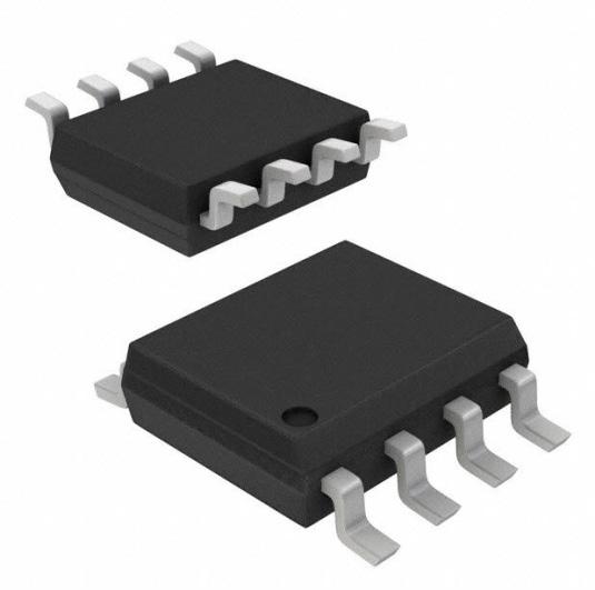
36 SMD IC Packages, continued Fig. 4.19: Surface mounted SO (Small Outline) IC package. (From Philips) Electronic Pack.. Chapter 4 Components for Electronic Systems Slide 36
37 Outline Encapsulation Maximum width SMD IC Packages, continued SO Maximum width Maximum length Lead end to lead end [mm] [mm] [mm] SO-8 4,0 5,00 6,2 SO-8 7,6 7,6 12,4 SO-14 4,0 8,75 6,2 SO-16 4,0 10,00 6,2 SO-16L 7,6 10,5 10,65 SO-20 7,6 13,0 10,65 SO-24 7,6 15,6 10,65 SO-28 7,6 18,1 10,65 VLO-40 7,6 15,5 12,8 VSO-56 11,1 21,6 15,8 Table 4.3: Dimensions for SO- and VSO packages. Centre-to-centre lead distance is normally 50 mils, except for VSO-40 with 30 mils and VSO-56 with 0.75 mm. Electronic Pack.. Chapter 4 Components for Electronic Systems Slide 37

38 SMD IC Packages: Plastic Leaded Chip Carrier (PLCC) Fig. 4.20: Plastic leaded chip carrier with (PLCC). They are normally square with an equal number of terminals on all four sides (top). For large DRAMs, the package has terminals on only two sides, also being called SOJ. The bottom figure shows a 1 or 4 Mbit DRAM package. Electronic Pack.. Chapter 4 Components for Electronic Systems Slide 38
39 SMD IC Packages: Plastic Leaded Chip Carrier (PLCC) Leads Format Lead pitch Maximum body dimensions [AxB] [mm] Maximum Device Dimensions (LxW) [mm] Typical Height (C) [mm] [mm] 20 5x5 1,27 9,1x9,1 10,1x10,1 3,5-4,7 28 7x7 1,27 11,6x11,6 12,6x12,6 3,5-4, x11 1,27 16,8x16,8 17,8x17,8 3,5-4, x13 1,27 19,3x19,3 20,3x20,3 3,5-4, x17 1,27 24,4x24,4 25,4x25,4 3,5-4,7 18 5x4 1,27 10,9x7,5 11,9x8,5 3,5-4,7 28 9x5 1,27 14,1x9,0 15,1x10,0 3,5-4,7 32 9x7 1,27 14,1x11,6 15,1x12,6 3,5-4,7 Table 4.4: Dimensions for PLCC packages. Format means the number of terminals on two neighbouring sides. Electronic Pack.. Chapter 4 Components for Electronic Systems Slide 39
40 Leadless Chip Carrier (LLCC) Leaded Ceramic Chip Carrier (LDCC) Fig a): The various types of ceramic chip carriers [4.15]. Types A -D to the left are leadless (LLCC), whereas types A and B to the right are meant for mounting leads (LDCC). Electronic Pack.. Chapter 4 Components for Electronic Systems Slide 40

41 Leadless Chip Carrier (LLCC) Fig b): LLCC packages, additional details. The longest terminal is to designate electrical terminal number 1 in the circuit. Electronic Pack.. Chapter 4 Components for Electronic Systems Slide 41
42 Leadless Chip Carrier (LLCC), continued Leads Format Pad Pitch (p) [mm] Maximum Dimension (AxB) [mm] 20 5x5 1,27 9,1x9,1 28 7x7 1,27 11,6x11, x11 1,27 16,8x16, x13 1,27 19,3x19, x17 1,27 24,4x24, x21 1,27 29,6x29,6 18 5x4 1,27 10,9x7,5 28 9x5 1,27 14,1x9,0 32 9x7 1,27 14,1x11,6 Table 4.5. LLCCs, dimensions. Electronic Pack.. Chapter 4 Components for Electronic Systems Slide 42

43 Leaded Ceramic Chip Carrier (LDCC) Fig. 4.22: Leaded ceramic chip carriers. Electronic Pack.. Chapter 4 Components for Electronic Systems Slide 43
44 Leaded Ceramic Chip Carrier (LDCC), continued Fig. 4.23: Various shapes of the leads, and leadless termination for comparison. Electronic Pack.. Chapter 4 Components for Electronic Systems Slide 44

45 Flatpacks Fig. 4.24: Quad flatpack with leads on all four sides. Flatpacks are usually made of plastic or ceramic. They have leads on four or two sides. Electronic Pack.. Chapter 4 Components for Electronic Systems Slide 45
46 Mini-flatpacks Fig. 4.25: Mini-flatpacks is a name for higher density flatpacks: Typically terminals and a pitch of 25 mils. Electronic Pack.. Chapter 4 Components for Electronic Systems Slide 46

47 TapePak Fig. 4.26: National Semiconductor s TapePak component packages are specified with terminal numbers between 40 and close to 600. To the left we see a 40 leads TapePak in the form it is received by the user with a protective ring around it, and test points outside the ring. To the right is TapePak 40 after excising and lead bending, seen from above and from the side. Electronic Pack.. Chapter 4 Components for Electronic Systems Slide 47
48 High Performance Packages Multilayer ceramic, Al 2 O 3 or AlN Ground planes Controlled characteristic impedance Thermal vias Electronic Pack.. Chapter 4 Components for Electronic Systems Slide 48
49 High Performance Packages Fig. 4.27: Thermal via-holes in the printed circuit board, for better heat conduction. Electronic Pack.. Chapter 4 Components for Electronic Systems Slide 49

50 High Performance Packages Fig. 4.28: Multilayer package for high frequency GaAs circuits with 3 ground planes, 2 voltage planes, 1 signal layer and a top conductor layer for contacts and sealing (Triquint). Electronic Pack.. Chapter 4 Components for Electronic Systems Slide 50

51 High Performance Packages, continued Fig. 4.29: Multichip package for memory module in a Hitachi high-performance computer [4.18]. The module contains 6 ECL chips, mounted by flip chip. Electronic Pack.. Chapter 4 Components for Electronic Systems Slide 51
52 Packages: Future Trends (1995) Fig. 4.30: Comparison between the size of various package forms for an integrated circuit with approximately 64 terminals. Electronic Pack.. Chapter 4 Components for Electronic Systems Slide 52
53 Packages: Future Trends, continued Fig. 4.31: History and prognosis for the use of various sizes of passive SMD components, in percentage of the total number. Electronic Pack.. Chapter 4 Components for Electronic Systems Slide 53
54 Metallization of Terminals Passives Ag in alloy with Pd, Ni barrier, Sn/Pb Ag in solder alloy With adhesive mounting: ICs No Sn/Pb on terminal Au removed Sn/Pb coating Electronic Pack.. Chapter 4 Components for Electronic Systems Slide 54
55 Terminal Metallization, Solderability and Reliability Fig. 4.32: Strain at fracture of solder fillet as function of gold concentration in the solder metal, relative to value without gold. Electronic Pack.. Chapter 4 Components for Electronic Systems Slide 55
56 Electrostatic Discharges (ESD) Unprotected MOS: Max 5-80 V on input before destroyed Triboelectricity: >>1000 V discharge Billions of $ damage annually Protected circuits tolerate V Extensive precautions in industry, handling and packing Electronic Pack.. Chapter 4 Components for Electronic Systems Slide 56
57 Electrostatic Discharges Component Damages and Precautions Fig. 4.33: MOS transistor schematically. The gate oxide is very vulnerable for damage by electrostatic discharge. Gate oxides down below 200 Å (20 nm) are now used. Electronic Pack.. Chapter 4 Components for Electronic Systems Slide 57

58 Electrostatic Discharges - Component Damages and Precautions, continued Fig. 4.34: CMOS circuit exposed to electrostatic damage: Silicon has molten in a small area. Picture size 5µm x 5µm. Electronic Pack.. Chapter 4 Components for Electronic Systems Slide 58
59 Electrostatic Discharges - Component Damages and Precautions, continued Fig. 4.35: ESD protection circuit at in- and outputs for MOS and for bipolar circuits. Electronic Pack.. Chapter 4 Components for Electronic Systems Slide 59
60 Component Packaging Paper tape (hole mounted passives) Blister tape (SMD passives, discretes, small ICs) Sticks (DIPs, SMD ICs) Waffle trays (Flatpacks) Stack magazine Bulk: Not suited for automatic mounting Electronic Pack.. Chapter 4 Components for Electronic Systems Slide 60

61 Component Packaging for Automatic Placement Fig. 4.36: Blister tape for surface mounted components. Standard dimensions for 8 mm wide tape. Electronic Pack.. Chapter 4 Components for Electronic Systems Slide 61

62 Component Packaging for Automatic Placement Fig. 4.37: Plastic sticks as packaging for SMD integrated circuits. Electronic Pack.. Chapter 4 Components for Electronic Systems Slide 62

63 Component Packaging for Automatic Placement Fig. 4.38: Waffle trays packaging for flatpacks to the left, frame for stacking of single component to the right. Electronic Pack.. Chapter 4 Components for Electronic Systems Slide 63
64 End of Chapter 4 Components for Electronic Systems Important issues: Components: Distinguish between the different components Packages for electronic devices : Distinguish between the different packages Electrostatic discharges Component packaging: Used for automatic assembly machines Electronic Pack.. Chapter 4 Components for Electronic Systems Slide 64
65 Some perspectives on home task on requirements extraction FYS4260/FYS9260 Frode Strisland 65
66 Generally about requirements Requirements must be verifiable (it has to be possible to decide whether a requirements is met). Examples of ways to test a requirement: Demonstration: The requirement is verified through real-time demonstration Inspection: The requirement is verified by visual examination of documentation, service components and/or technical design/device design. Testing: The requirement is verified by experimental testing that a predefined acceptance level have been reached (testing is typically carried out for physical and performance type requirements). FYS4260/FYS9260 Frode Strisland 66
67 Requirements priority: Unless stated otherwise, requirements are "MUST" When working with requirements, one will have conflicting interestes between requirements. Priorities are therefore recommended, for example: HIGH: The requirement MUST be implemented and is seen as a central element in the project/product MEDIUM: The requirement SHOULD PREFERABLY be implemented within the project/product, but alternative solutions can be found. A requirement set to MEDIUM will, in the project development process, be handled as follows: If cost, timescales and resources allow it, it will be implemented. If the requirement is not implemented, resources will be put into ensuring that the development is adapted and adjusted so the requirement can be implemented at a later stage after the present project. LOW: The requirement WOULD have been nice to have but is not seen as central. FYS4260/FYS9260 Frode Strisland 67


68 The weather station case The weather station can be categorized as consumer electronics CE marking: By affixing the CE marking on a product, a manufacturer is declaring, at its sole responsibility, conformity with all of the legal requirements to achieve CE marking which allows free movement and sale of the product throughout the European Economic Area Implications: Compliance includes WEEE and RoHS on electronics waste and manufacturing Electromagnetic Compliance ISM radio + several other FYS4260/FYS9260 Frode Strisland 68
69 Environmental effects What does outdoor environment mean with respect to offices climate Larger temperature variations Frost, sunshine 100 relative humidity (CONDENSING) Rain What happens if the device is mounted up-sidedown? Storage and transport: Airline transport can be -55C and at atm FYS4260/FYS9260 Frode Strisland 69
70 Consider what is the environment Malestrom Printed Circuits Handbook 6th ed FYS4260/FYS9260 Frode Strisland 70
71 Handling What happens if the unit falls to the ground? Or if a user uses a hammer to mount the unit? Is it possible to change battery without breaking the seal towards the outside? FYS4260/FYS9260 Frode Strisland 71
72 Packaging of temperature sensor Very fast temperature response not needed can therefore for example place the temperature sensor on a corner of the PCB that is expected to be thermally in good contact with the environments Temperature technologies Thermistors Surface resistors (e.g. Pt100-type elements) FYS4260/FYS9260 Frode Strisland 72

73 Barometric pressure sensor Pressure sensor challenge: there must be a hole into the pressure sensitive MEMS membrane What happens if water enters into this hole? And freezes? Approach: Seal the hole with e.g. a Teflon membrane for outdoor use. For more extreme situations, e.g. a divers watch, a separation membrane must be used In the current case suggest placing the barometric sensor in the indoor station part? Example device: LPS25HB from ST Microelectronics FYS4260/FYS9260 Frode Strisland 73
 Idea: Consider using the humidity temperature calibration sensor as temperature sensor.")
74 Humidity sensor Same problem as the pressure sensor: Humidity and water can enter into the sensor. Solution: Add a protective membrane of e.g. Teflon (GoreTex) Idea: Consider using the humidity temperature calibration sensor as temperature sensor. FYS4260/FYS9260 Frode Strisland 74
75 Overall packaging Humidity absorption is a general problem for outdoor electronics. It is probably acceptable to apply FR4 circuit board technology, but it may be a good idea to coat the finished circuit board with a water resistant/repellent film/paint. FYS4260/FYS9260 Frode Strisland 75
Chapter 11: Passives: Discrete, Integrated, and Embedded. Johan Liu
 Chapter 11: Passives: Discrete, Integrated, and Embedded Johan Liu jliu@chalmers.se 1 Types of Passive Components 2 Embedded passive devices: advantages Reduced system mass, volume and footprint. Individual
DATA SHEET SURFACE-MOUNT CERAMIC MULTILAYER CAPACITORS Low-Inductance X5R / X7R
 Product Specification November 21, 2016 V.1 DATA SHEET SURFACE-MOUNT CERAMIC MULTILAYER CAPACITORS - X5R / X7R 6.3 V TO 50 V 10 nf to 1 uf RoHS compliant & Halogen Free 2 SCOPE This specification describes
Embedded Passives..con0nued
 Embedded Passives..con0nued Why Embedded Passives? Improves the packaging efficiency System-on-Package (SOP); SLIM integration Reducing size Eliminating substrate assembly Minimizing solder joint failure
ST 79 SMD. ESCC 3003/006 - cases C & D ELECTRICAL AND CLIMATIC CHARACTERISTICS. DIMENSIONS (mm) HOW TO ORDER
 HOW TO ORDER") ST 79 SMD ESCC 3003/006 - cases C & D Wet tantalum capacitors Hermetically sealed tantalum cases Very high capacitance Very low ESR High ripple current SMD Polarized types ELECTRICAL AND CLIMATIC CHARACTERISTICS
ST 79 SMD ESCC 3003/006 - cases C & D Wet tantalum capacitors Hermetically sealed tantalum cases Very high capacitance Very low ESR High ripple current SMD Polarized types ELECTRICAL AND CLIMATIC CHARACTERISTICS
Guide for Conformal Coated Tantalum Capacitors
 Guide for Conformal Coated Tantalum Capacitors INTRODUCTION Tantalum electrolytic capacitors are the preferred choice in applications where volumetric efficiency, stable electrical parameters, high reliability,
Novel Technique for Flip Chip Packaging of High power Si, SiC and GaN Devices. Nahum Rapoport, Remtec, Inc.
 Novel Technique for Flip Chip Packaging of High power Si, SiC and GaN Devices Nahum Rapoport, Remtec, Inc. 1 Background Electronic Products Designers: under pressure to decrease cost and size Semiconductor
Tantalum Wet Electrolytic Capacitor
 INTRODUCTION The structure of a Tantalum Wet Electrolytic Capacitor consists of four main elements: a primary electrode (anode), dielectric, a secondary electrode system (cathode) and a wet (liquid) electrolyte.
Bulk Metal Foil Resistors. Precision Resistor Network Devices (PRND)
") Bulk Metal Foil Resistors Precision Resistor Network Devices (PRND) 5 April 2011 Designing with Foil Resistors in Hermetic Packages Product/Division Vishay Foil Resistors Name When relative performance
Bulk Metal Foil Resistors Precision Resistor Network Devices (PRND) 5 April 2011 Designing with Foil Resistors in Hermetic Packages Product/Division Vishay Foil Resistors Name When relative performance
10 Manor Parkway, Suite C Salem, New Hampshire
 Micro-Precision Technologies (MPT) is an independent manufacturer of hybrid integrated circuits, multichip modules, and high-precision thick film substrates for the military, medical, avionics, optoelectronics,
LTCC SYSTEMS and LTCC DESIGN RULES
 LTCC SYSTEMS and LTCC DESIGN RULES Low Temperature Co-fired Ceramic revision status: G page 1 of 19 Table of Contents: 1 General page 3 2 Commercial LTCC tape systems page 4 3 Design possibilities page
Oki M A-60J 16Mbit DRAM (EDO)
") Construction Analysis Oki M5117805A-60J 16Mbit DRAM (EDO) Report Number: SCA 9707-545 Global Semiconductor Industry the Serving Since 1964 17350 N. Hartford Drive Scottsdale, AZ 85255 Phone: 602-515-9780
Construction Analysis Oki M5117805A-60J 16Mbit DRAM (EDO) Report Number: SCA 9707-545 Global Semiconductor Industry the Serving Since 1964 17350 N. Hartford Drive Scottsdale, AZ 85255 Phone: 602-515-9780
Chapter 2 Manufacturing Process
 Digital Integrated Circuits A Design Perspective Chapter 2 Manufacturing Process 1 CMOS Process 2 CMOS Process (n-well) Both NMOS and PMOS must be built in the same silicon material. PMOS in n-well NMOS
National Semiconductor LM2672 Simple Switcher Voltage Regulator
 Construction Analysis National Semiconductor LM2672 Simple Switcher Voltage Regulator Report Number: SCA 9712-570 Global Semiconductor Industry the Serving Since 1964 17350 N. Hartford Drive Scottsdale,
CX Thin Fil s. Resistors Attenuators Thin-Film Products Thin-Film Services. ISO 9001:2008 RoHS/REACH Compliant ITAR Compliant
 CX Thin Fil s Resistors Attenuators Thin-Film Products Thin-Film Services www.cxthinfilms.com ISO 9001:2008 RoHS/REACH Compliant ITAR Compliant www.cxthinfilms.com sales@cxthinfilms.com +1 (401) 461-5500
Micron Semiconductor MT4LC16M4H9 64Mbit DRAM
 Construction Analysis Micron Semiconductor MT4LC16M4H9 64Mbit DRAM Report Number: SCA 9705-539 Global Semiconductor Industry the Serving Since 1964 15022 N. 75th Street Scottsdale, AZ 85260-2476 Phone:
The 3D Silicon Leader. Company Presentation. SMTA Houston, 14th March 2013
 The 3D Silicon Leader Company Presentation SMTA Houston, 14th March 2013 Who are we? Independent Company located in Caen, Normandy, France Dedicated to manufacturing of leading edge Integrated Passive
Tantalum Through-Hole Capacitors Hermetically Sealed T551 Axial Polymer Hermetic Seal (PHS) 125ºC Series
 125ºC Series") Tantalum Through-Hole Capacitors Hermetically Sealed Overview The KEMET T551 Series Polymer Hermetic Seal (PHS) is a tantalum capacitor with a Ta anode and Ta2O5 dielectric. A conductive organic polymer
Tantalum Through-Hole Capacitors Hermetically Sealed Overview The KEMET T551 Series Polymer Hermetic Seal (PHS) is a tantalum capacitor with a Ta anode and Ta2O5 dielectric. A conductive organic polymer
Overview. Benefits. Tantalum Polymer Capacitors Hermetically Sealed T551 Axial & T556 Surface Mount 125 C
 Overview The KEMET T551 axial leaded and T556 surface mount polymer hermetically sealed (PHS) devices are tantalum capacitors with a Ta anode and Ta 2 O 5 dielectric. A conductive, organic polymer replaces
ATSC Automotive Grade Silicon Capacitors
 ATSC Automotive Grade Silicon Capacitors Rev 1.1 Key Features Qualified according to AEC-Q100 Ultra long life @ 200 C High stability of capacitance value: Temperature
Rockwell R RF to IF Down Converter
 Construction Analysis Rockwell R6732-13 RF to IF Down Converter Report Number: SCA 9709-552 Global Semiconductor Industry the Serving Since 1964 17350 N. Hartford Drive Scottsdale, AZ 85255 Phone: 602-515-9780
Overview. Benefits. Applications. Tantalum Through-Hole Capacitors Hermetically Sealed T550 Axial Polymer Hermetic Seal (PHS) 105 C and DLA Series
 105 C and DLA Series") Tantalum Through-Hole Capacitors Hermetically Sealed T550 Axial Polymer Hermetic Seal (PHS) 105 C and DLA Series Overview The KEMET T550 Series Polymer Hermetic Seal (PHS) is a tantalum capacitor with
Tantalum Through-Hole Capacitors Hermetically Sealed T550 Axial Polymer Hermetic Seal (PHS) 105 C and DLA Series Overview The KEMET T550 Series Polymer Hermetic Seal (PHS) is a tantalum capacitor with
Intel Pentium Processor W/MMX
 Construction Analysis Intel Pentium Processor W/MMX Report Number: SCA 9706-540 Global Semiconductor Industry the Serving Since 1964 15022 N. 75th Street Scottsdale, AZ 85260-2476 Phone: 602-998-9780 Fax:
Guide for Tantalum Solid Electrolyte Chip Capacitors with Polymer Cathode
 Guide for Tantalum Solid Electrolyte Chip Capacitors with Polymer Cathode INTRODUCTION Tantalum electrolytic capacitors are the preferred choice in applications where volumetric efficiency, stable electrical
Solid Tantalum Chip Capacitors TANTAMOUNT, Conformal Coated, Maximum CV
 Solid Tantalum Chip Capacitors TANTAMOUNT, Conformal Coated, Maximum CV 595D PERFORMANCE CHARACTERISTICS www.vishay.com/doc?40194 Operating Temperature: -55 C to +125 C (above 85 C, voltage derating is
Guide for Molded Tantalum Capacitors
 Guide for Molded Tantalum Capacitors INTRODUCTION Tantalum electrolytic capacitors are the preferred choice in applications where volumetric efficiency, stable electrical parameters, high reliability,
Micron Semiconductor MT5C64K16A1DJ 64K x 16 SRAM
 Construction Analysis Micron Semiconductor MT5C64K16A1DJ 64K x 16 SRAM Report Number: SCA 9412-394 Global Semiconductor Industry the Serving Since 1964 17350 N. Hartford Drive Scottsdale, AZ 85255 Phone:
Overview. Benefits. Applications. Tantalum Through-Hole Capacitors Molded Radial T330 Molded Radial
 Overview The KEMET T330 polar-type, radial lead, rectangular Precision Molded Tantalum (PMT) capacitors are primarily designed for applications that demand full use of the premium space available in printed
Motorola MPA1016FN FPGA
 Construction Analysis Motorola MPA1016FN FPGA Report Number: SCA 9711-561 Global Semiconductor Industry the Serving Since 1964 17350 N. Hartford Drive Scottsdale, AZ 85255 Phone: 602-515-9780 Fax: 602-515-9781
Dallas Semicoductor DS80C320 Microcontroller
 Construction Analysis Dallas Semicoductor DS80C320 Microcontroller Report Number: SCA 9702-525 Global Semiconductor Industry the Serving Since 1964 15022 N. 75th Street Scottsdale, AZ 85260-2476 Phone:
SGS-Thomson L4990 Controller
 Construction Analysis SGS-Thomson L4990 Controller Report Number: SCA 9710-560 Global Semiconductor Industry the Serving Since 1964 17350 N. Hartford Drive Scottsdale, AZ 85255 Phone: 602-515-9780 Fax:
Maximum MAX662 12V DC-DC Converter
 Construction Analysis Maximum MAX662 12V DC-DC Converter Report Number: SCA 9512-445 Global Semiconductor Industry the Serving Since 1964 17350 N. Hartford Drive Scottsdale, AZ 85255 Phone: 602-515-9780
Motorola MC68360EM25VC Communication Controller
 Construction Analysis EM25VC Communication Controller Report Number: SCA 9711-562 Global Semiconductor Industry the Serving Since 1964 17350 N. Hartford Drive Scottsdale, AZ 85255 Phone: 602-515-9780 Fax:
UBSC/ULSC 60 + GHz Ultra Broadband Silicon Capacitors Surface Mounted
 Rev 2.5 UBSC/ULSC 60 + GHz Ultra Broadband Silicon Capacitors Surface Mounted Key Features Ultra broadband performance up to 60 + GHz Resonance free Phase stability Ultra high stability of capacitance
Solid Tantalum Chip Capacitors TANTAMOUNT, Low Profile, Low ESR, Conformal Coated, Maximum CV
 592D Solid Tantalum Chip Capacitors TANTAMOUNT, Low Profile, Low ESR, Conformal Coated, Maximum CV PERFORMANCE CHARACTERISTICS www.vishay.com/doc?40194 Operating Temperature: -55 C to +125 C (above 85
Overview. Benefits. Applications. Tantalum Polymer Capacitors Hermetically Sealed T550 Axial & T555 Surface Mount 105 C
 Overview The KEMET T550 axial leaded and T555 surface mount polymer hermetically sealed (PHS) devices are tantalum capacitors with a Ta anode and Ta 2 O 5 dielectric. A conductive organic polymer replaces
SGS-Thomson M28C K EEPROM
 Construction Analysis SGS-Thomson M28C64-121 64K EEPROM Report Number: SCA 9710-559 Global Semiconductor Industry the Serving Since 1964 17350 N. Hartford Drive Scottsdale, AZ 85255 Phone: 602-515-9780
IPC-AJ-820A Assembly and Joining Handbook. The How and Why of All Things PCB & PCA
 IPC-AJ-820A Assembly and Joining Handbook The How and Why of All Things PCB & PCA 1 Scope To provide guidelines and supporting info for the mfg of electronic equipment To explain the HOW TO and WHY Discussions
Motorola PC603R Microprocessor
 Construction Analysis Motorola PC603R Microprocessor Report Number: SCA 9709-551 Global Semiconductor Industry the Serving Since 1964 17350 N. Hartford Drive Scottsdale, AZ 85255 Phone: 602-515-9780 Fax:
UMC UM F-7 2M-Bit SRAM
 Construction Analysis UMC UM 613264F-7 2M-Bit SRAM Report Number: SCA 9609-511 Global Semiconductor Industry the Serving Since 1964 15022 N. 75th Street Scottsdale, AZ 85260-2476 Phone: 602-998-9780 Fax:
Ultra High Precision Bulk Metal Foil Technology 4 Resistor Surface Mount Hermetic Network with 0.5 ppm/ C TCR Tracking and % Tolerance Match
 Ultra High Precision Bulk Metal Foil Technology 4 Resistor Surface Mount Hermetic Network with 0.5 ppm/ C TCR Tracking and 0.005 % Tolerance Match INTRODUCTION Vishay model SMNH networks incorporate all
VTC VM365830VSJ Pre-Amp
 Construction Analysis VTC VM365830VSJ Pre-Amp Report Number: SCA 9708-549 Global Semiconductor Industry the Serving Since 1964 17350 N. Hartford Drive Scottsdale, AZ 85255 Phone: 602-515-9780 Fax: 602-515-9781
Tantalum Capacitors. Product Catalog
 Tantalum Capacitors Product Catalog Product Catalog 189 Tantalum Capacitors A Worldwide presence St Nazaire Paris Chanteloup Antigny Illange Marmoutier Pessac Seattle Rochester Orlando Casablanca Ho Chi
Chapter 4 Fabrication Process of Silicon Carrier and. Gold-Gold Thermocompression Bonding
 Chapter 4 Fabrication Process of Silicon Carrier and Gold-Gold Thermocompression Bonding 4.1 Introduction As mentioned in chapter 2, the MEMs carrier is designed to integrate the micro-machined inductor
NEOCAPACITOR Technical Note
 NEOCAPACITOR Technical Note Document No. EC35EJ1VUM Date Published September 1997 N Printed in Japan NEOCAPACITOR Technical Note,,,,, 1997 [MEMO] CONTENTS 1. WHAT IS NEOCAPACITOR?... 1 2. WHAT IS POLYPYRROLE?...
Solid Tantalum Surface Mount Chip Capacitors, TANTAMOUNT, Molded Case, Very Low DCL
 Solid Tantalum Surface Mount Chip Capacitors, TANTAMOUNT, Molded Case, Very Low DCL PERFORMANCE / ELECTRICAL CHARACTERISTICS www.vishay.com/doc?40192 Operating Temperature: -55 C to +125 C (above 85 C
High Stability Resistor Chips (< 0.25 % at Pn at 70 C during 1000 h) Thick Film Technology
 Thick Film Technology") High Stability Resistor Chips (< 0.25 % at Pn at 70 C during 0 h) Thick Film Technology thick film resistor chips are specially designed to meet very stringent specifications in terms of reliability, stability
High Stability Resistor Chips (< 0.25 % at Pn at 70 C during 0 h) Thick Film Technology thick film resistor chips are specially designed to meet very stringent specifications in terms of reliability, stability
NTC Thermistors. Mounting instructions. Date: January 2018
 NTC Thermistors Mounting instructions Date: January 2018 EPCOS AG 2018. Reproduction, publication and dissemination of this publication, enclosures hereto and the information contained therein without
TOWARD MEMS!Instructor: Riadh W. Y. Habash
 TOWARD MEMS!Instructor: Riadh W. Y. Habash Students are presented with aspects of general production and manufacturing of integrated circuit (IC) products to enable them to better liaise with and participate
RoHS Compliant (6/6) according to Directive 2002/95/EC when ordered with 100% Sn solder.
 according to Directive 2002/95/EC when ordered with 100% Sn solder.") Overview The KEMET Organic Capacitor (KO-CAP) is a tantalum capacitor with a Ta anode and Ta 2 O 5 dielectric. A conductive organic polymer replaces the traditionally used MnO 2 as the cathode plate of
Overview The KEMET Organic Capacitor (KO-CAP) is a tantalum capacitor with a Ta anode and Ta 2 O 5 dielectric. A conductive organic polymer replaces the traditionally used MnO 2 as the cathode plate of
Solid Tantalum Chip Capacitors TANTAMOUNT, Low Profile, Low ESR, Conformal Coated, Maximum CV
 592D Solid Tantalum Chip Capacitors TANTAMOUNT, Low Profile, Low ESR, Conformal Coated, Maximum CV PERFORMANCE CHARACTERISTICS www.vishay.com/doc?40088 Operating Temperature: -55 C to +125 C (above 85
Mosel Vitelic MS62256CLL-70PC 256Kbit SRAM
 Construction Analysis Mosel Vitelic MS62256CLL-70PC 256Kbit SRAM Report Number: SCA 9703-499 Global Semiconductor Industry the Serving Since 1964 17350 N. Hartford Drive Scottsdale, AZ 85255 Phone: 602-515-9780
New Component Technologies Enable More Robust and Reliable Power System Design
 New Component Technologies Enable More Robust and Reliable Power System Design APEC2016 Chris Reynolds Technical Marketing Manager AVX Corporation (843) 424 1209 AVX Corporation 2016 http://www.avx.com
Packaging Technologies for SiC Power Modules
 Packaging Technologies for SiC Power Modules Masafumi Horio Yuji Iizuka Yoshinari Ikeda ABSTRACT Wide bandgap materials such as silicon carbide (SiC) and gallium nitride (GaN) are attracting attention
XBSC/UBDC/UBSC/BBSC/ULSC 100 µm & 400 µm - Assembly by soldering
 Assembly by soldering General description This document describes the attachment techniques recommended by Murata* for their pre-bumped and un-bumped silicon capacitors on the customer substrates. This
Solid Tantalum Chip Capacitors TANTAMOUNT, Low Profile, Low ESR, Conformal Coated, Maximum CV
 591D Solid Tantalum Chip Capacitors TANTAMOUNT, Low Profile, Low ESR, Conformal Coated, Maximum CV PERFORMANCE CHARACTERISTICS www.vishay.com/doc?40194 Operating Temperature: -55 C to +125 C (above 85
Hitachi A 64Mbit (8Mb x 8) Dynamic RAM
 Dynamic RAM") Construction Analysis Hitachi 5165805A 64Mbit (8Mb x 8) Dynamic RAM Report Number: SCA 9712-565 Global Semiconductor Industry the Serving Since 1964 17350 N. Hartford Drive Scottsdale, AZ 85255 Phone:
Construction Analysis Hitachi 5165805A 64Mbit (8Mb x 8) Dynamic RAM Report Number: SCA 9712-565 Global Semiconductor Industry the Serving Since 1964 17350 N. Hartford Drive Scottsdale, AZ 85255 Phone:
Guide for Molded Tantalum Capacitors
 INTRODUCTION Tantalum electrolytic capacitors are the preferred choice in applications where volumetric efficiency, stable electrical parameters, high reliability, and long service life are primary considerations.
FYS4260/FYS9260: Microsystems and Electronics Packaging and Interconnect Printed Circuit Boards
 FYS4260/FYS9260: Microsystems and Electronics Packaging and Interconnect Printed Circuit Boards Interior detail from an Apple iphone 5 printed circuit board Learning objectives Understand how printed wiring/circuit
Product Selection Guide 2012
 Product Selection Guide 2012 One world. One KEMET. Table of Contents Aluminum Electrolytic Capacitors Ceramic Capacitors EMI Filters Film Capacitors Tantalum Capacitors 6 12 34 38 52 3 One world. One
Application Note. Capacitor Selection for Switch Mode Power Supply Applications
 Application Note AN37-0013 Capacitor Selection for Switch Mode Power Supply Applications 1. Introduction Faced with the availability of multiple capacitor options for use in high reliability SMPS applications,
vpolytan TM Polymer Surface Mount Chip Capacitors, Low ESR, Leadframeless Molded Type
 vpolytan TM Polymer Surface Mount Chip Capacitors, Low ESR, Leadframeless Molded Type T59 PERFORMANCE / ELECTRICAL CHARACTERISTICS Operating Temperature: -55 C to +105 C Capacitance Range: 15 μf to 470
NKK NR4645LQF Bit RISC Microprocessor
 Construction Analysis NKK NR4645LQF-133 64-Bit RISC Microprocessor Report Number: SCA 9707-547 Global Semiconductor Industry the Serving Since 1964 17350 N. Hartford Drive Scottsdale, AZ 85255 Phone: 602-515-9870
Analog Devices ADSP KS-160 SHARC Digital Signal Processor
 Construction Analysis Analog Devices ADSP-21062-KS-160 SHARC Digital Signal Processor Report Number: SCA 9712-575 Global Semiconductor Industry the Serving Since 1964 17350 N. Hartford Drive Scottsdale,
Solid Tantalum Chip Capacitors TANTAMOUNT, Conformal Coated
 195D Solid Tantalum Chip Capacitors TANTAMOUNT, Conformal Coated PERFORMANCE / ELECTRICAL CHARACTERISTICS www.vishay.com/doc?40194 Operating Temperature: -55 C to +125 C (above 85 C, voltage derating is
Silicon Wafer Processing PAKAGING AND TEST
 Silicon Wafer Processing PAKAGING AND TEST Parametrical test using test structures regularly distributed in the wafer Wafer die test marking defective dies dies separation die fixing (not marked as defective)
Integrated Circuit Engineering Corporation EPROM
 EPROM There was lots of discussion and many technical papers covering the promises of EPROM (typically Flash) at the IEDM conference last December, but here as in the other memory areas, not much in the
Applications. Capacitance Code Version. The last two digits represent significant figures. The first digit specifies the total number of digits.
 Screw Terminal Aluminum Electrolytic Capacitors PEH205 Series, +125 C Overview Applications KEMET's PEH205 Series of capacitors has a polarized all-welded design, heavy duty screw terminals, extended cathode
High performance and high reliability passives for miniature medical devices based upon Silicon technologies. Laurent Dubos INEMI May 2011
 High performance and high reliability passives for miniature medical devices based upon Silicon technologies Laurent Dubos INEMI May 2011 IPDIA overview Company located in Caen, Normandy, France Started
Solid Tantalum Chip Capacitors TANTAMOUNT, Conformal Coated Case, Ultra Low ESR, DLA Approved
 DLA 13008 Solid Tantalum Chip Capacitors TANTAMOUNT, Conformal Coated Case, Ultra Low ESR, DLA Approved FEATURES High reliability Surge current testing per MIL-PRF-55365 options Ultra-low ESR Tin / lead
Beam Leads. Spider bonding, a precursor of TAB with all-metal tape
 Beam Leads The vast majority of chips are intended for connection with thermosonic bonds: all other methods require some modification to the wafer. As early as 1972, Jordan described three gang-bonding
Overview. Benefits. Applications. Tantalum Through-Hole Capacitors Radial Dipped T350, T351, T352, T353, T354, T355 & T356 UltraDip II Polar
 T350, T351, T352, T353, T354, T355 & T356 Ultraip II Polar Overview The KEMET Ultraip II offers quality instrument and entertainment system designs that are widely recognized and advantages inherent to
Solid Tantalum Surface Mount Capacitors TANTAMOUNT Conformal Coated, Low ESR, Military, MIL-PRF-55365/13 Qualified
 Solid Tantalum Surface Mount Capacitors TANTAMOUNT Conformal Coated, Low ESR, Military, MIL-PRF-55365/13 Qualified CWR26 Vishay PERFORMANCE CHARACTERISTICS www.vishay.com/doc?40211 Operating Temperature:
Solid Tantalum Surface Mount Capacitors TANTAMOUNT Conformal Coated, Military MIL-PRF-55365/4 Qualified
 CWR06 Solid Tantalum Surface Mount Capacitors TANTAMOUNT Conformal Coated, Military MIL-PRF-55365/4 Qualified PERFORMANCE CHARACTERISTICS www.vishay.com/doc?40211 Operating Temperature: -55 C to +125 C
PRODUCT TYPE CASE CAPACITANCE VOLTAGE DIMENSIONS (MM) MAX DESCRIPTION CODE CODE RANGE RANGE WIDTH LENGTH HEIGHT
 MAX DESCRIPTION CODE CODE RANGE RANGE WIDTH LENGTH HEIGHT") Tantalum FEATURES Solid Tantalum Molded and Coated Versions CECC and MIL Approved Styles High Reliability and Low ESR models CASE CAPACITANCE VOLTAGE DIMENSIONS (MM) MAX CODE CODE RANGE RANGE WIDTH LENGTH
Tantalum FEATURES Solid Tantalum Molded and Coated Versions CECC and MIL Approved Styles High Reliability and Low ESR models CASE CAPACITANCE VOLTAGE DIMENSIONS (MM) MAX CODE CODE RANGE RANGE WIDTH LENGTH
Comparison of the 4 solutions: Summary of Flex Crack Countermeasures in MLCCs"
 Flex Crack Countermeasures in MLCCs Outline When a crack occurs on the element of an MLCC (Multilayer Ceramic Chip Capacitor) due to depaneling of the print circuit board, screw fastening, or shock from
Long-term reliability of SiC devices. Power and Hybrid
 Long-term reliability of SiC devices Power and Hybrid Rob Coleman Business Development and Applications Manager TT electronics, Power and Hybrid Roger Tall Product Specialist Charcroft Electronics Ltd
Solid Tantalum Surface Mount Chip Capacitors TANTAMOUNT Molded Case, High Performance, Automotive Grade
 Solid Tantalum Surface Mount Chip Capacitors TANTAMOUNT Molded Case, High Performance, Automotive Grade PERFORMANCE / ELECTRICAL CHARACTERISTICS www.vishay.com/doc?40215 Operating Temperature: -55 C to
Reference Only. Spec. No. JENF243E-0003Q-01 P 1 / 8. Chip EMIFIL LC Combined Type for Large Current NFE61PT 1H9 Reference Specification
 Spec. No. JENF243E-0003Q-01 P 1 / 8 Chip EMIFIL LC Combined Type for Large Current NFE61PT 1H9 Reference Specification 1. Scope This reference specification applies to Chip EMIFIL LC Combined Type for
SUPPLIER PACKAGING CODE REQUIREMENTS EFFECTIVE DATE 2/20/2018
 Change summary: The revision as of this date Created Packaging Code Q from PWB packaging prohibiting the use of Amine-Free anti stat material known as Pink Poly. CODE A: Best Commercial Practice (EFF DATE:
MQ Series Medical Grade MLCC General Specifications
 General Specifications GENERAL DESCRIPTION AVX offers a wide variety of medically qualified passive components. Medical devices require the utmost reliability with respect to the components incorporated
Overview. Applications. Benefits. Part Number System. Single-Ended Conductive Polymer Aluminum Solid Electrolytic Capacitors A C
 Single-Ended Conductive Polymer Aluminum Solid Electrolytic Capacitors Overview Applications KEMET s A758 Single-Ended Conductive Polymer Aluminum Solid Electrolytic Capacitors offer longer life and greater
NEC 79VR5000 RISC Microprocessor
 Construction Analysis NEC 79VR5000 RISC Microprocessor Report Number: SCA 9711-567 Global Semiconductor Industry the Serving Since 1964 17350 N. Hartford Drive Scottsdale, AZ 85255 Phone: 602-515-9780
Plasma Etching Rates & Gases Gas ratios affects etch rate & etch ratios to resist/substrate
 Plasma Etching Rates & Gases Gas ratios affects etch rate & etch ratios to resist/substrate Development of Sidewalls Passivating Films Sidewalls get inert species deposited on them with plasma etch Creates
HTSC SiCap 400µm - NiAu finishing - Assembly by soldering
 General description This document describes the attachment techniques recommended by Murata* for their HTSC silicon capacitors on the customer substrates. This document is non-exhaustive. Customers with
Revised RoHS Annex As of 1 st January Entered force 24 September 2010, corrected 29 September 2010*
 Revised RoHS Annex As of 1 st January 2011. Entered force 24 September 2010, corrected 29 September 2010* 1 1 Mercury in single capped (compact) fluorescent lamps not exceeding (per burner): 1(a) For general
5. Packaging Technologies Trends
 5. Packaging Technologies Trends Electronic products and microsystems continue to find new applications in personal, healthcare, home, automotive, environmental and security systems. Advancements in packaging
1/2W, 0805 Low Resistance Chip Resistor (Lead / Halogen free)
") 1. Scope 1/2W, 0805 (Lead / Halogen free) This specification applies to 1.2mm x 2.0mm size 1/2W, fixed metal film chip resistors rectangular type for use in electronic equipment. 2. Type Designation RL
1. Scope 1/2W, 0805 (Lead / Halogen free) This specification applies to 1.2mm x 2.0mm size 1/2W, fixed metal film chip resistors rectangular type for use in electronic equipment. 2. Type Designation RL
LPSC SiCap 100µm NiAu finishing - Assembly by soldering
 General description This document describes the attachment techniques recommended by Murata* for their LPSC silicon capacitors on the customer substrates. This document is non-exhaustive. Customers with
Recommendation for Handling and Assembly of Infineon Hallsensor PG-SSO Packages
 Recommendation for Handling and Assembly of Infineon Hallsensor PG-SSO Packages Additional Information DS4, August 2012 Edition 2012-08-06 Published by Infineon Technologies AG 81726 Munich, Germany 2012
Solid Tantalum Chip Capacitors, MICROTAN, High CV Leadframeless Molded Automotive Grade
 Solid Tantalum Chip Capacitors, MICROTAN, High CV Leadframeless Molded Automotive Grade TP8 Vishay Sprague FEATURES Highest capacitance-voltage product in industry in given case size Small sizes include
Electrical Specifications. Dielectric Withstanding Voltage 200V CSR2010 1W 200V ±100 ppm/ºc (1)
") Features: 0402 to 1225 sizes available Power ratings to 3W Low inductance less than 0.2nH typically RoHS compliant and halogen-free Non-standard resistance values available 0815, 2010 and 2512 sizes available
Features: 0402 to 1225 sizes available Power ratings to 3W Low inductance less than 0.2nH typically RoHS compliant and halogen-free Non-standard resistance values available 0815, 2010 and 2512 sizes available
VLSI Design and Simulation
 VLSI Design and Simulation CMOS Processing Technology Topics CMOS Processing Technology Semiconductor Processing How do we make a transistor? Fabrication Process Wafer Processing Silicon single crystal
Manufacturing Technologies for MEMS and SMART SENSORS
 4 Manufacturing Technologies for MEMS and SMART SENSORS Dr. H. K. Verma Distinguished Professor (EEE) Sharda University, Greater Noida (Formerly: Deputy Director and Professor of Instrumentation Indian
KGC SCIENTIFIC Making of a Chip
 KGC SCIENTIFIC www.kgcscientific.com Making of a Chip FROM THE SAND TO THE PACKAGE, A DIAGRAM TO UNDERSTAND HOW CPU IS MADE? Sand CPU CHAIN ANALYSIS OF SEMICONDUCTOR Material for manufacturing process
ROLINX Laminated Busbar. Design Rules Version 01 (12/2015)
") ROLINX Laminated Busbar Design Rules Version 01 (12/2015) Content 1. Introduction... 03 7. Features... 13 2. Configuration...03 8. Thermal parameters... 14 3. Products... 04 9. General parameters... 14
ROLINX Laminated Busbar Design Rules Version 01 (12/2015) Content 1. Introduction... 03 7. Features... 13 2. Configuration...03 8. Thermal parameters... 14 3. Products... 04 9. General parameters... 14
Applications. Capacitance Code (pf) Tolerance
 Tolerance") Surface Mount Conductive Polymer Aluminum Solid Electrolytic Capacitors Overview Applications KEMET s A767 Series of Surface Mount Conductive Polymer Aluminum Solid Electrolytic Capacitors offer longer
Surface Mount Conductive Polymer Aluminum Solid Electrolytic Capacitors Overview Applications KEMET s A767 Series of Surface Mount Conductive Polymer Aluminum Solid Electrolytic Capacitors offer longer
Facedown Termination for Higher C/V - Lower ESL Conductive-Polymer SMT Capacitors
 Facedown Termination for Higher C/V - Lower ESL Conductive-Polymer SMT Capacitors Edward Chen 1, Ken Lai 2, John Prymak 3, Mike Prevallet 3 KEMET Electronics Corp. Taiwan Branch, 3-4F, No. 148, Section
vpolytan TM Polymer Surface Mount Chip Capacitors, Low Profile, Leadframeless Molded Type
 T52 vpolytan TM Polymer Surface Mount Chip Capacitors, Low Profile, Leadframeless Molded Type PERFORMANCE / ELECTRICAL CHARACTERISTICS Operating Temperature: -55 C to +105 C Capacitance Range: 47 μf to