Humidity Effect on the Structure of Electrospun Core-Shell PCL-PEG Fibers for Tissue Regeneration Applications
|
|
|
- Benedict Martin
- 5 years ago
- Views:
Transcription

1 Western University Electronic Thesis and Dissertation Repository May 2014 Humidity Effect on the Structure of Electrospun Core-Shell PCL-PEG Fibers for Tissue Regeneration Applications Adam P. Golin The University of Western Ontario Supervisor Dr. Wankei Wan The University of Western Ontario Graduate Program in Chemical and Biochemical Engineering A thesis submitted in partial fulfillment of the requirements for the degree in Master of Engineering Science Adam P. Golin 2014 Follow this and additional works at: Part of the Biomaterials Commons, Biomedical Devices and Instrumentation Commons, Molecular, Cellular, and Tissue Engineering Commons, Polymer and Organic Materials Commons, and the Polymer Science Commons Recommended Citation Golin, Adam P., "Humidity Effect on the Structure of Electrospun Core-Shell PCL-PEG Fibers for Tissue Regeneration Applications" (2014). Electronic Thesis and Dissertation Repository This Dissertation/Thesis is brought to you for free and open access by Scholarship@Western. It has been accepted for inclusion in Electronic Thesis and Dissertation Repository by an authorized administrator of Scholarship@Western. For more information, please contact tadam@uwo.ca.
2 Humidity effect on the structure of electrospun core-shell PCL-PEG fibers for tissue regeneration applications (Thesis format: Monograph) By Adam Golin Department of Chemical and Biochemical Engineering A thesis submitted in partial fulfillment of the requirements for the degree of Masters of Engineering Science The School of Graduate and Postdoctoral Studies The University of Western Ontario London, Ontario, Canada Adam Golin 2014
3 Abstract With the aim of creating a biodegradable scaffold for tympanic membrane tissue regeneration, core-shell nanofibers composed of a poly(caprolactone) shell and a poly(ethylene glycol) core were created using a coaxial electrospinning technique. In order to create fibers with an optimal core-shell morphology, the effect of relative humidity on the core-shell nanofibers was systematically studied, with a FITC-BSA complex encapsulated in the core to act as a model protein. The core-shell nanofibers were electrospun at relative humidity values of 20, 25, 30, and 40% within a glove box with humidity control. The core-shell morphology of the fibers was studied via the use of scanning electron microscopy, transmission electron microscopy, and laser scanning confocal microscopy. It was found that humidity does alter the core-shell morphology by altering the rate at which the fibers dry and that there is an optimal humidity for the coaxial electrospinning of core-shell fibers. In addition, the fibers were fashioned into a biomimetic scaffold for TM regeneration using a rotating mandrel to align the nanofibers and to create a dual layer fibrous mat similar to the structure of native TM collagen fibers. Keywords Electrospinning, tissue engineering, coaxial electrospinning, environmental parameters, tympanic membrane, relative humidity ii
4 Acknowledgments This thesis has required a great deal of work over the past two years and it would not have been possible without the support and guidance of those around me. I would like to thank Dr. Wankei Wan for his considerable input and guidance over the course of this work. He pushed me to work hard and often provided challenge in the form of insightful questioning. I would also like to thank all the members of the lab group as it has been a pleasure to work with you all. Specifically I would like to thank Dr. Jian Liu for assisting me with many aspects of this project and answering many of questions, Betty Li for teaching me how to perform electrospinning techniques, Julia La for helping me in the collection of samples. I would like to thank Karen Nygard, Dr. Richard Gardiner, and everyone at the Biotron for teaching and assisting me with the imaging techniques used in this thesis. Finally I would like to thank my family for the unconditional support and love they have given me over the course of my academic career, and for pushing me to always produce the best work possible. iii
5 Table of Contents Abstract... ii Acknowledgments...iii List of Tables... viii List of Figures... ix List of Abbreviations...xii 1 Introduction Background & Literature Review Tympanic Membrane Structure & Function Perforation & Treatment Tissue Egineering Basic Approach Scaffolds for Tissue Engineering Electrospinning History Set-Up & Operating Principles Electrostatically Induced Jets & Bending Instability Electrospinning Parameters Needle Tip and Collector Electrode Separation Applied Voltage Solution Feed Rate Polymer Molecular Weight Solution Viscosity Solution Concentration Solution Electrical Conductivity Temperature iv
6 2.4.9 Relative Humidity Summary of Electrospinning Parameters Coaxial Electrospinning Coaxial Electrospinning Set-Up & Fundamentals Coaxial Electrospinning Process Parameters Orientation Applied Voltage Solution Feed Rate Solution Viscosity Solution Concentrations Solvent Miscibility Solvent Vapor Pressure Solution Conductivity Ambient Parameters Summary of Coaxial Electrospinning Parameters Fiber Alignment Importance of Fiber Alignment Methods for Fiber Alignment Measuring Fiber Alignment Materials for Coaxial Electrospinning Poly(caprolactone) Trifluoroethanol Poly(ethylene glycol) FITC-BSA Model Protein Materials and Methods Materials Solutions Polymer Shell Solution v
7 3.2.2 Protein Core Solution Humidity Control Coaxial Electrospinning Random Fibers Aligned Fibers Stacked Layers of Aligned Fibers Fiber Characterization Scanning Electron Microscopy (SEM) Transmission Electron Microscopy (TEM) Laser Scanning Confocal Microscopy (LSCM) Resin Embedding and Ultramicrotoming Image Analysis Fiber Diameter FFT Analysis Results & Discussion Selection of Electrospinning Parameters Set-Up Orientation Solution Parameters Voltage Optimization Other Parameters Humidity Control Characterization of the Core-Shell Fibers Fiber Diameter and Morphology TEM Imagining Ultramicrotoming Laser Scanning Confocal Microscopy Aligned Fibrous Mats Selection of Mandrel Speed vi
8 4.4.2 Characterization of Aligned Core-Shell Fibers Comparison of Aligned Solid and Core-Shell Fibers Creation of Dual Layer Aligned Fibers Characterization of Dual Layer Scaffold Comparison to Rat Tympanic Membrane Summary and Conclusions Future Work Bibliography Appendix A: Dry Box Protocol Appendix B: SEM Images Appendix C: Confocal Images Curriculum Vitae vii
9 List of Tables Table 1: Summary of electrospinning parameters and their effects Table 2: Summary of coaxial electrospinning parameters and their effects Table 3: Summary of results obtained in this work, showing how RH quantitatively affects fiber diameter, and qualitatively affects the fiber morphology and core-shell structure Table 4: Coaxial electrospinning parameters Table 5: Statistics on fiber diameter measurements for the relative humidity values tested viii
10 List of Figures Figure 1: A) Radial fiber arrangement viewed from ear canal B) Circumferential fiber arrangement on middle ear side C) Local perpendicular arrangement...4 Figure 2: Whipping motion and Taylor cone formation at needle tip...9 Figure 3: Vertical and horizontal set-ups for electrospinning Figure 4: Scaffold with a high degree of beading Figure 5: Charged jet regions Figure 6: Coaxial electrospinning set-up, coaxial needle, and coaxial Taylor cone Figure 7: Taylor cone formation in coaxial electrospinning A) Formation of pendant droplet B) Elongation of droplet due to electrostatic force C) Formation of Taylor Cone and jet ejection Figure 8: Orientation of coaxial electrospinning set-up Figure 9: As voltage increases from left to right, a drooping droplet is seen on the left due to voltage below critical value. In the center is a typical Taylor cone as the voltage is within the acceptable range. On the right is the formation of two polymer jets due to voltage above the critical range Figure 10: A) Rotating drum electrode B) Rotating disc electrode C) Rotating wire-drum electrode.. 35 Figure 11: Parallel plate electrode Figure 12: 2 plate, 4 plate, and 6 plate patterned electrodes Figure 13: A) Aligned fibers B) FFT spectrum of aligned fibers C) Plot of FFT spectrum for aligned fibers D) Random fibers E) FFT of random fibers F) Plot of FFT for random fibers Figure 14: Chemical structure of PCL Figure 15: Chemical structure of TFE Figure 16: Chemical structure of PEG Figure 17: Chemical Structure of FITC Figure 18: Humidity Controlled Chamber ix
11 Figure 19: Light resistant neoprene tubing Figure 20: Collector electrode for unaligned fibers Figure 21: Rotating mandrel with variable speed motor Figure 22: DC motor for mandrel rotation Figure 23: Bead free fibers produced using selected parameters Figure 24: Fiber diameter vs. Relative Humidity Figure 25: Diameter distribution plots at A) 40 B) 30 C) 25 and D) 20% RH Figure 26: Count vs. Logarithm of diameter for data depicted in Figure 24 A) 40 B) 30 C) 25 and D) 20% RH Figure 27: Fusing of fibers at 40% RH. Fiber fusion is indicated with black arrows Figure 28: Ribbon fibers at 20% RH. Fibers indicated with black arrows Figure 29: 30% RH Fibers (Left) and 25% RH Fibers (Right) Figure 30: Fick's law of diffusion for a cylinder with radius r followed by the expansion to the governing equation of mass diffusion Figure 31: Effect of humidity on fiber diameter from literature data Figure 32: TEM images showing core-shell fibers at A) 40% RH B) 30% RH C) 25% RH D) 20% RH65 Figure 33: TEM images showing solid fibers at A) 40% RH B) 30% RH C) 25% RH D) 20% RH Figure 34: TEM images showing split fibers at A) 40% RH B) 30% RH C) 25% RH D) 20% RH Figure 35: Ultramicrotome of 40% RH Fibers. Red arrows indicate solid PCL, blue indicates ideal coreshell, and black indicates reverse contrast Figure 36: Ultramicrotome cross section of fibers at 30% RH. Red arrows indicate core-shell fibers 70 Figure 37: Cross section of 25% RH fibers showing ring morphologies. Red arrows indicate ring fibers, black indicate core-shell x
12 Figure 38: Cross section of 20% RH fibers. Red arrows indicate collapsed fibers, black indicate ring structures Figure 39: Confocal-DIC images of fibers spun at 40% RH Figure 40: Confocal-DIC images of fibers spun at 30% RH Figure 41: Highly localized FITC-BSA distribution at 25% RH Figure 42: Confocal-DIC images of fibers electrospun at 20% RH Figure 43: FFT of fibers spun at A) 7400 RPM B) 6500 RPM C) 5600 RPM D) 0 RPM. The images on the far right are graphical plots of the data obtained from the FFT spectra in the central images. It can be seen that as mandrel rotation speed decreases, the plots which are generated possess more signal peaks, indicating a smaller degree of orientation Figure 44: Diameter distribution of fibers aligned at 6500 RPM Figure 45: LSCM of aligned fibrous scaffold Figure 46: Left) Aligned PCL fibers. Right) Aligned core-shell fibers Figure 47: Diameter distribution of dual layer fibrous scaffold Figure 48: SEM images showing the dual layer structure of the scaffold. Left) 500x Magnification. Right) 3000x magnification Figure 49: LSCM images showing the dual layer scaffold structure Figure 50: Z-Stack image of the dual layer scaffold Figure 51: FFT plots of A) the TM B) electrospun scaffold Figure 52: Comparison of TM and electrospun scaffold FFT plots Figure 53: Dry Box Schematic xi
13 List of Abbreviations TM Tympanic Membrane AOM Acute otitis media TE Tissue engineering ECM PCL Extra-cellular matrix Poly(capro-lactone) PLLA Poly(L-lactid-co-caprolactone) PDLA RH Poly(D,L-lactic acid) Relative humidity DC Direct current RSM Response surface methodology PVA PEO Poly(vinyl alcohol) Poly(ethylene oxide) PEG Poly(ethylene glycol) PVP Poly(vinyl pyrrolidone) PLA 2D FFT Poly(lactic acid) 2D Fast Fourier Transform TFE Trifluoroethanol FITC Fluorescein isothiocyanate BSA DCV Bovin serum albumin Direct current voltage SEM Scanning electron microscope xii
14 TEM Transmission electron microscope LSCM DMF Laser scanning confocal microscopy N,N-dimethylyformamide PAN poly(acrylonitrile) xiii
15 1 Introduction Extreme disease and injury can cause damage to vital organs and tissues, impairing function and requiring medical intervention through transplants and drug therapy. Modern medical science has provided transplant treatments in the form of allografts or autografts, however these pose challenges in the form of supply and immune rejection [1]. Synthetic prostheses have also been developed which are able to perform the required task but are unable to fully restore function of the damaged or lost tissue [1]. Eardrum perforations for example, affect approximately 1-3% of the American population [2], and can be successfully repaired using surgical techniques. However, this surgical method is unable to fully restore hearing for affected individuals due to the limitations posed by currently available graft materials. Given these limitations of traditional transplant and graft technology, tissue engineering has emerged as an area of research which aims to regenerate the damaged tissues. This regeneration is achieved through the use of biomaterials which provide cells with the necessary biological cues to induce cell growth [3]. The tissue engineering process involves harvesting healthy cells from the patient s body, expanding these cells, and culturing them on a 3D porous support structure known as a scaffold [3]. Ideally the cells adhere to the scaffold, proliferate, and deposit extra-cellular matrix at the same rate at which the scaffold degrades, resulting in healthy, functional tissue [4]. The tissue engineering scaffold is the structure which supports and guides cell growth, and as such it is critical to the success of any tissue engineering approach. Much research has gone into developing an ideal scaffold for many different tissue engineering applications, and several design criteria have been established [5]. The scaffold should be porous in order to provide sufficient space for cell adhesion, biocompatible, biodegradable and produce nontoxic byproducts, mechanically strong to withstand physiological stresses that will be placed on it, and structurally similar to the tissue being replaced. Fabricating a scaffold which meets these design criteria poses its own challenge, and electrospinning has emerged as a simple and cost effective production method. Electrospinning 1
16 utilizes a high voltage electric field to draw a polymer solution flowing out of a capillary into solid nanofibers. A typical electrospinning set-up has a spinneret positioned some distance away from a collector plate, both of which are electrically conductive. Polymer solution is fed to the spinneret utilizing a syringe pump and a high voltage power supply is used to apply the electrostatic field. Through variation of the parameters governing the electrospinning process, the fiber diameter and morphology can be controlled to a degree. Electrospinning is a highly versatile process, with a large number of polymers able to be processed into fibers by electrospinning. Many variations on this process have been developed such as coaxial electrospinning, which allows for the encapsulation of bioactive molecules within the electrospun fibers. Coaxial electrospinning provides a feasible method by which materials for drug delivery and controlled release applications can be readily produced. Scaffolds creating using coaxial electrospinning are able to allow the controlled release of growth factors required for stimulating cell migration and proliferation, thereby enhancing the tissue engineering process. This work aims to investigate the effect of relative humidity on the structure of the fibers created through the coaxial electrospinning process in order to assess the optimal conditions for coreshell fiber production. There is a distinct lack of research into how environmental parameters affect the structure of coaxial nanofibers, a structure which is critical to the coaxial nanofibers performing their intended function. A complete understanding of how all parameters involved in electrospinning affect the final fiber morphology is critical to success of tissue engineering approaches which utilize coaxial electrospinning. Using the knowledge gained from the investigation of the effect of humidity on the core-shell fibers, a biomimetic scaffold was then fashioned for use in tympanic membrane tissue engineering. 2
17 2 Background & Literature Review 2.1 Tympanic Membrane Structure & Function The mammalian tympanic membrane (TM), or the eardrum, is what separates the outer ear from the inner ear and is the first step in the transmission of sound vibrations to receptors in the ear. It transmits the vibrations from the air in the external ear canal to the small bones in the middle ear. The TM is comprised of two sections, the pars tensa and the pars flaccida. The pars flaccida is a small section of ear drum tissue which is much more compliant and contains blood vessels, nerve endings and mast cells [6]. The pars tensa comprises the rest of the eardrum and is tightly stretched across the ear canal [7]. The pars tensa is composed of three layers: the epidermal layer which is continuous with the mucosa of the middle ear; lamina propria which is composed mainly of collagen organized into radial and circumferential fibrous layers; and the mucosal epithelium [6]. When it comes to the function of the eardrum, it is the lamina propria which is the layer of interest since the organization of the collagen layers provides it with its mechanical and acoustic properties [8]. These two layers of organized collagen are stacked one atop the other, with the upper layer possessing collagen fibers that run circumferentially around the membrane (Figure 1B), and the lower layer composed of fibers that run radially outward from the malleus which is located at the center of the membrane (Figure 1A) [8]. This structure is evident in the study carried out by Kawabata et al. [8] and has also been verified to be present in Wistar rats (Figure 1). Kuypers et al. [9] studied the thickness of both fresh and preserved human eardrums, finding that there was no significant difference between the two. However, there was a large variation in thickness at different points on the TM as well as large variations in thickness between individuals, with the average thickness varying between μm [9]. 3

![synthetic materials being investigated such as collagen [10], [11], silk fibroin[11] [13], and chitosan [14].](/docs-images/80/82509762/images/18-1.jpg "Since the lamina propria provides the tissue with its acoustic properties and is critical to its function, this layer is of interest to those")

18 A B C Figure 1: A) Radial fiber arrangement viewed from ear canal B) Circumferential fiber arrangement on middle ear side C) Local perpendicular arrangement There is a growing interest in researching a suitable artificial scaffold for tissue engineering of the TM, with a wide variety of synthetic materials being investigated such as collagen [10], [11], silk fibroin[11] [13], and chitosan [14]. Since the lamina propria provides the tissue with its acoustic properties and is critical to its function, this layer is of interest to those investigating tissue engineering applications, as its structure must be accurately mimicked by any tissue engineering scaffold Perforation & Treatment Tympanic membrane perforations are holes in the eardrum, caused by trauma or infection. The total incidence of these perforations is unknown but it is estimated that 1-3% of the American 4
19 population is affected [2]. Severe trauma such as a fractured skull or exposure to high-level impulsive sound pressure can cause the eardrum to become perforated. As well, acute otitis media (AOM) is a common childhood infection and can cause eardrum perforation via inflammation and continuous break down of the collagen structure [7]. The TM is able to spontaneously heal small perforations via epithelial cell migration [15], and it is estimated that approximately 80% of perforations heal in this manner [2]. When a perforation fails to heal on its own within 3 months, it is deemed to be a chronic perforation and surgical intervention is required [2]. Exactly what causes chronicity in TM perforations is not clear but some hypotheses point to a lack of structural support, mechanical disruption of the epithelial margin, and bacterial infection preventing the proliferation and migration of the epithelial cells [2]. Chronic TM perforations are treated via the surgical method known as tympanoplasty or myringoplasty which aim to heal the perforation, prevent recurring infections and restore hearing [2]. During this procedure, the damaged membrane is repaired using graft materials taken from a selection of autologous or homologous tissues. The selection of the correct graft material is critical in this operation as the selected material should have the same mechanical and acoustic properties as the TM in order to fully restore hearing. Temporalis fascia, cartilage, AlloDerm, and perichondrium are all common graft materials, however they possess their own inherent limitations. Temporalis fascia, along with other autologous tissues, is associated with donor site morbidity, additional incisions, and a long operation time [11]. AlloDerm is a commercial alternative to autologous tissues, and is derived from human cadaver donor skin. AlloDerm is ten times thicker than normal TM, making it unable to mimic and restore the complex microstructure of the TM [11]. A number of xenographic materials have also been investigated for use in myringoplasty such as porcine small intestinal submucosa, however these graft materials have the potential to evoke an immune response or rejection [11]. Since the currently available materials for myringoplasty are not able to restore the originally complex microanatomy of the eardrum, hearing cannot be fully restored to pre-perforation levels, which has instigated the investigation of a tissue engineering approach to perforation treatment [16]. Such an approach 5
20 involves the creation of a tissue engineering scaffold from synthetic materials. This scaffold would be applied to the perforation through a myringoplasty, and the perforation allowed to heal. 2.2 Tissue Egineering Basic Approach Tissue engineering (TE) is a complex area of study that draws from the principles of biology, materials science, and engineering to develop in vivo tissue substitutes which will replace or repair damaged tissues, restoring full function [17]. In a tissue engineering approach, healthy cells are first harvested from a donor site and expanded in cell culture. After expansion, the cells are seeded onto a porous scaffold along with any necessary growth factors and biological signaling molecules in order to promote cell proliferation throughout the scaffold. The cells are then allowed to proliferate on the scaffold and transplanted into the patient at the treatment site. Ideally, as the cells proliferate throughout the scaffold, the scaffold will begin to degrade and be replaced by cell-generated extra-cellular matrix (ECM) [17]. When the scaffold has fully degraded, all that should remain is healthy, functioning tissue that is identical to the original. By using the patient s own cells, the TE approach has a number of advantages over more traditional transplant therapies using allografts and xenografts as immune rejection will not occur, and it is not limited by an inadequate supply of donor tissue Scaffolds for Tissue Engineering The TE scaffold is an artificial 3D porous scaffold which plays a critical role in guiding and manipulating cell growth and function. The scaffold acts as a temporary ECM, promoting cell growth and adhesion, and providing mechanical support for the neo-tissue that is being grown. By nature of its purpose, scaffold design is one of the most important stages in any tissue engineering approach. The material must be carefully selected so that the rate of degradation 6
21 closely matches the rate of new ECM formation so that cell support is maintained throughout tissue development. There are a number of critical design criteria which must be met when creating a TE scaffold. First, the scaffold must be biocompatible such that neither the scaffold nor its degradation products are toxic to the surrounding tissues and do not provoke an immune response [1]. Second, the scaffold must be biodegradable and follow reliable degradation kinetics, so that it may be fully eliminated from the body after a predetermined amount of time [18]. Third, the scaffold should be highly porous to provide sufficient surface area and space for cell growth, allow uniform cell distribution throughout the scaffold, as well as efficient transfer of nutrients and elimination of wastes [1]. Furthermore, the scaffold should be inherently biomimetic, being mechanically and structurally similar to the tissue it is replacing on a micro- and nanoscale-level so that it may tolerate any forces acting on it and provide an ideal environment for cell growth. Cellular responses to micrometer-range topographic features have been well established, affecting cell growth and proliferation [19]. However, topographic features on the nanoscale-range have also been shown to elicit cell responses ranging from cell adhesion, orientation, modulation of signaling pathways, and gene expression [19]. This diverse cell response to microscale- and nanoscale topographies must be considered when designing a TE scaffold, and the topographies should be controlled to mimic native tissue, in order to elicit the most appropriate response for tissue engineering. Lastly, the material chosen to fabricate the scaffold should be easily processed into its desired shape via a number of scaffold fabrication methods such as electrospinning, solvent-casting, or gas-foaming [1]. Porous 3D scaffolds have been successfully fabricated using these methods from biodegradable polymers such as poly(capro-lactone) (PCL) [20], poly(vinyl alcohol) [21], and poly(glycolic acid) [1]. Scaffolds can also be fabricated from natural polymers such as collagen and chitosan [1] [22]. Finally, scaffolds can be created through the decellularization of existing tissues, creating a scaffold composed of natural ECM and that does not need to be processed into the desired shape [23], [24]. 7
22 2.3 Electrospinning History Electrospinning is a broadly used technique for fiber formation and utilizes electrostatic forces to produce polymer fibers ranging from nanometer to micrometer diameter. The phenomenon which drives electrospinning has been known for over 100 years, and was first observed by Rayleigh in 1897, and studied in more detail by Zeleny in 1914 [25]. However it was not until 1979 that Taylor would investigate the jet forming process and publish his results, with the first biomedical applications beginning to be investigated around the same time [26]. By the mid-1990s, researchers had started to realize the potential of nanofiber production, with electrospinning taking the lead as the most versatile production method, and in the last decade researchers have begun to look to electrospinning to fabricate nanofibrous assemblies [27] Set-Up & Operating Principles A standard electrospinning set up consists of a number of components, each of which can be altered to create fibers of a desired morphology. However, a basic set up consists of a syringe loaded with the desired polymer solution and fitted with a needle, a syringe pump, a grounded collector plate, and a high voltage power supply [25]. As the polymer solution is pumped through the needle, a droplet is formed at the tip, held in place by its own surface tension. When voltage is applied across the needle and collector plate, with the needle being positively charged and the collector being grounded, a static charge is induced on the surface of the droplet [28]. There exists a critical voltage, above which the induced static charge overcomes the surface tension of the droplet, causing it to distort into a conical shape known as a Taylor Cone, and a single jet to be ejected from the tip of this cone [28]. When this fiber is ejected, it begins to travel the space between the needle tip and collector electrode, as it travels the solvent evaporates and the jet undergoes a rapid whipping motion (Figure 2). It was initially believed that the primary jet splits into multiple filaments that are deposited [29], however it has since been shown that the fiber undergoes a whipping motion which causes it to elongate and decrease in diameter [30]. 8
23 Figure 2: Whipping motion and Taylor cone formation at needle tip The electrospinning equipment can be set-up with either a vertical or horizontal arrangement as shown in Figure 3. In the vertical set-up the needle is positioned directly above the collector plate, with gravity and the electrostatic force acting in the same direction. The horizontal set-up has the needle positioned so that it is facing the collector plate, with the electrostatic force and gravity working in perpendicular directions. A study by Rodoplu et al [31], indicated that the effect of the gravitational force is negligible when compared to the electrostatic force being exerted on the polymer solution, allowing for electrospinning regardless of the setup orientation. However, they saw that gravity does affect the shape of the droplet at the needle tip, thereby changing the shape of the Taylor cone, and ultimately altering the fiber diameter [31]. Another study by Yang et al. investigated the differences between the two orientations and found that the vertical set-up produces fibers with a smaller average diameter due to the combined effect of gravity and the electrostatic force causing the fibers to be more elongated [32]. As well, these results showed that the vertical set-up produced fibers with a much wider range of fiber diameters than that of the fibers produced with the horizontal set-up [32]. 9
24 Figure 3: Vertical and horizontal set-ups for electrospinning Electrostatically Induced Jets & Bending Instability As has been stated, the shape of the droplet at the tip of the needle is held by its own surface tension. As a potential difference is applied, static charge accumulates on this droplet, with the charge concentrating on the tip of protruding droplet. It is this charge concentration that causes the droplet to eventually distort and form the conical shape of the Taylor cone [30] [33]. As the droplet distorts into this conical shape, charge further accumulates at the tip of the cone, which is what allows a fluid jet to be ejected and deposited as nanofibers [34]. As the jet leaves the Taylor cone and begins to travel from the needle tip to the collector electrode it is subject to a number of forces which influence the final morphology of the deposited fibers. When the jet first leaves the Taylor cone, there is still a large amount of solvent present, meaning the jet is in liquid form. As the tendency of all liquids, surface tension minimizes the surface area by forming spherical droplets. If the electrostatic charge on the jet is not high enough the surface tension causes the jet to break up into droplets, an effect known as Rayleigh instability [35]. One of the advantages electrospinning has over other scaffold creation techniques is the ability to create scaffolds with a high surface area to volume ratio, meaning that the scaffold possesses a high porosity. However, when the electrospinning jet experiences 10
![Rayleigh instability, beaded fibers (Figure 4) are deposited on the collector electrode [36].](/docs-images/80/82509762/images/25-0.jpg "The presence of beads on the final scaffold is less than desirable as they greatly reduce the surface area to volume ratio of the electrospun scaffold.")
25 Rayleigh instability, beaded fibers (Figure 4) are deposited on the collector electrode [36]. The presence of beads on the final scaffold is less than desirable as they greatly reduce the surface area to volume ratio of the electrospun scaffold. Figure 4: Scaffold with a high degree of beading The ideal electrospinning mode is achieved when the electrostatic force continually exceeds the effect of surface tension. This results in a liquid jet stream whose diameter steadily decreases as it approaches the collector electrode and at the same time, the polymer solvent gradually evaporates, resulting in fully dried fibers being deposited. This is also known as steady state electrospinning and can be achieved by optimizing the processing parameters in order to reduce Rayleigh instability. Regardless of whether or not Rayleigh instability is present and the electrospinning process is steady state, the electrically charged jet passes through two regions (Figure 5A). In the first region, the electrically charged jet travels in a straight path from the Taylor cone [37]. At the end of this straight segment exists a conical diaphanous shape with its vertex at the end of the straight segment [37]. This cone is the envelope in space of the complex pathway taken by the jet as it moves from the needle to the collector, also known as whipping or bending instability. Images obtained by Baumgarten show that this jet is continuously bending up until the moment it is deposited on the collector electrode [38]. The conical shape (Figure 5B) of the jet path 11
26 envelope arises due to the evaporation of solvent and solidification of the polymer fiber. As the solvent evaporates, the jet becomes more viscous over time which increases the elastic modulus of the jet, resulting in an increase in the bending stiffness and the radius of the bending loops [30]. In addition, bending instability causes a reduction in the diameter of the charged jet and ultimately a reduction in the diameter of the solidified fibers. Figure 5: Charged jet regions Hohman et al. [29] identified three different instability modes of the electrospinning jet: (1) Rayleigh mode, which is dominated by surface tension and electrical effects on the jet are important; (2) asymmetric conducting mode; and (3) the whipping conducting mode. It is competition between the asymmetric conducting mode and the whipping conducting mode that is of greatest importance in the high-applied voltage fields [29]. These two modes are electrostatically driven and the dominant instability depends on the static charge density of the electrospinning jet, with the asymmetric mode dominant at low applied voltages, and the whipping mode dominant at higher applied voltages. The nature of these two conducting modes depends entirely on the fluid parameters of the jet such as viscosity, dielectric constant, and the conductivity [29]. While these empirical observations provide a wealth of information about the electrospinning process, accurate mathematical models would be an incredibly useful tool in the optimization of 12
27 the electrospinning process as opposed to traditional trial and error. A number of attempts have been made to mathematically model the process by various groups. Cui et al. [39] performed a regression analysis on empirical data in order to develop a set of equations relating fiber diameter to solution concentration and polymer molecular weight, Reneker et al. [37] modeled the viscoelasticity of the electrospinning jet using a linear Maxwell equation, and Hohman et al. [29] developed a slender-body theory for Newtonian fluids. While these mathematical models are a step in the right direction, none of them capture the complex interactions between electrospinning parameters nor do they provide an entirely theoretical model which can predict fiber diameter based on processing parameters. A combination of these mathematical models and empirical observations of the process can provide a good starting point for the selection of electrospinning parameters, but the process still must optimized by semi empirical methods. 2.4 Electrospinning Parameters As has been discussed, electrospinning is a highly complex process with a large number of parameters interacting to form nano- or micro-fibers. A number of these parameters have been designated as process parameters as they are associated with the set-up of the electrospinning equipment. These parameters influence the diameter and morphology of the fibers and in some cases are critical for electrospinning to even be possible. Process parameters include variables such as the electric field strength which can be altered by changing the applied voltage between needle and collector; solution properties such as viscosity, concentration, material, polymer molecular weight, and conductivity of the solution; as well as the separation between the needle tip and collector plate, and the solution feed rate. Many of these parameters are highly coupled and the alteration of one can have dramatic effects on the rest, for example viscosity, concentration and polymer molecular weight. Some of these parameters can also be altered through the addition of materials to the solution such as surfactants to decrease surface tension or ionizing salts to increase conductivity. 13
28 There are a set of parameters which have been designated as environmental parameters as they are associated with the ambient conditions surrounding the electrospinning set-up. These parameters tend to have an effect on the final morphology of the electrospun fibers by influencing one of the process parameters. Environmental parameters include variables such as temperature, relative humidity, vapor diffusivity, solvent vapor pressure, composition of surrounding atmosphere, and external air flow. Much like the process parameters, the environmental parameters tend to be coupled as well as being directly connected to many of the process parameters. For instance, a change in temperature will alter the viscosity of the polymer solution. While these parameters all have some effect on the morphology and diameter of the final electrospun fibers, they do not all have the same degree of influence. Some parameters such as applied voltage and solution concentration weakly affect the fiber diameter, while others such as viscosity and needle-collector separation strongly affect fiber diameter. Thompson et al. [40]systematically investigated the effects of thirteen electrospinning parameters by varying the values in an electrospinning model, and then ranked the effects of the parameters from strongest to weakest. Among the parameters with the strongest effects on the jet diameter were the needle-collector separation, viscosity, and volumetric charge density [40]. Parameters such as surface tension, polymer concentration, solution density, applied voltage, solvent vapor pressure, relative humidity, and vapor diffusivity were all determined to have a medium to minor effect on the diameter of the electrospinning jet [40]. This study did not take into account factors such as temperature, charge polarity, and external air-flow, all of which can influence the final fiber morphology by altering the process parameters Needle Tip and Collector Electrode Separation The distance between the needle tip and collector electrode is an easily manipulated parameter and can be used to greatly affect the diameter and morphology of the electrospun fibers. Generally speaking, there is an inverse relationship between needle-collector separation and fiber diameter, with a shorter distance corresponding with larger fibers and a larger distance with 14
29 smaller fibers. This is due to the change in space available for the whipping process to occur, resulting in a charged jet which undergoes less or more whipping, respectively [40]. However, it has also been found that there is a minimum separation required in order to give the fibers sufficient time to dry, as well as distances that are either too short or too large, resulting in a large degree of bead formation [25], [41], [42] Applied Voltage As the sole driving force of the electrospinning process, it would not be too great a leap in logic to say that the strength of the voltage affects the morphology of the fibers. Initial studies by Baumgarten [38] indicated that the voltage alters the shape of the Taylor cone; however there is a consensus that the strength of the applied voltage does not have a strong effect on the fiber diameter [25]. By increasing the applied voltage, the electric field surrounding the jet is stronger, which leads to a greater stretching of the polymer solution resulting in a reduction of the final fiber diameter [25]. However, since the stretching of the polymer depends largely on the viscosity of the solution, the degree to which applied voltage influences fiber diameter varies greatly with the material being spun and its concentration Solution Feed Rate The feed rate of the solution being electrospun is another critical parameter as it affects the jet velocity as well as the rate of material transfer. In general, there is a direct relationship between fiber diameter and solution feed rate, with a lower feed rate creating fibers with a lower fiber diameter and vice versa [43]. However, a low feed rate is much more desirable as it allows for sufficient drying of the jet prior to deposition on the collector and prevents bead formation seen at higher feed rates [25] Polymer Molecular Weight Molecular weight of a polymer has a significant effect on a number of solution properties such as viscosity, surface tension, conductivity, and dielectric strength, all parameters that have an effect 15
30 on the morphology of electrospun fibers [44]. High molecular weight polymers are preferred for use in electrospinning as they can provide the desired viscosity for fiber formation [25]. Molecular weight of the polymer is indicative of the number of chain entanglements when the polymer is in solution and therefore, the solution viscosity. When the molecular weight of the solution is too low the process tends towards bead formation, and higher molecular weight solutions form fibers with a larger average diameter [44]. For instance, Tan et al. [45] electrospun poly(l-lactid-cocaprolactone) (PLLA) with different molecular weights and showed that the low molecular weight PLLA formed non-uniform fibers with beading, and the high molecular weight PLLA was able to produce bead-free fibers Solution Viscosity Solution viscosity is one of the most important solution parameters in electrospinning as it has a direct effect on whether or not the solution can be electrospun. At very low viscosities there is no continuous fiber formation resulting in discontinuous fibers, and at high viscosities the ejection of the polymer jet from the needle tip becomes difficult. For a solution of low viscosity, surface tension becomes the dominant force which causes extreme beading to occur, while above a certain critical viscosity a continuous fibrous structure is formed [25]. When the viscosity is above this critical value which allows for bead-free electrospinning, a further increase in viscosity will result in an increase in average fiber diameter, as the jet will take much longer to elongate due to bending instability [46]. However, when the viscosity of a solution becomes too high, the shear between the solution and the spinneret wall is what prevents jet ejection from the needle tip Solution Concentration There exists a minimum solution concentration that allows for the formation of fibers via electrospinning. At low solution concentrations, a mixture of beads and fibers is produced since at a low concentration, there is a low viscosity, resulting in surface tension dominating the fiber formation process [25]. As the solution concentration increases, these beads transition to a fibrous morphology due to the increased viscosity. Further increasing the solution concentration, 16
31 results in a larger fiber diameter as viscoelastic forces can suppress the effect of surface tension, as was seen by Nezarati et al. [47]. However, when the solution concentration becomes too high, the viscoelastic forces begin to dominate, resulting in difficulties with jet ejection [44]. There is therefore a material specific range of concentrations that will allow for electrospinning. For instance, Dietzel et al. [48] showed that for poly(ethylene oxide) the range of electrospinnable concentrations is from 4-10 wt% Solution Electrical Conductivity As jet formation depends on charge build-up on the surface of the polymer droplet, all electrospinnable polymers are conductive to some degree. However, the degree of conductivity depends on the type of polymer, the solvent being used, as well as the presence of an ionizable salt. The degree of conductivity also has some bearing on the fiber diameter, with a high conductivity associated with a decrease in the fiber diameter [25]. Solutions with low conductivity do not allow for sufficient elongation of the jet, causing the dominance of surface tension and Rayleigh instability and resulting in beading of the fibers [25]. The conductivity of any given solution can be readily enhanced through the addition of ionic salts in order to achieve a desired morphology. Zong et al. [49] investigated the effects on morphology and diameter by adding NaCl, KH 2 PO 4, and HaH 2 PO 4 salts to poly(d,l-lactic acid) (PDLA) solutions and found that increased conductivity due to the presence of the salt produced beadles, small-diameter fibers Temperature Temperature has an indirect influence on the fiber diameter and morphology by influencing the viscosity of the electrospinning solution. There is an inverse relationship between temperature and viscosity, as an increase in temperature results in a decrease in viscosity. As previously discussed, a decrease in viscosity is associated with smaller diameter fibers meaning that an increase in temperature should result in smaller fibers [25]. Vrieze et al. [50] found that there is an interesting relationship between temperature and fiber diameter of poly(vinylpyrrolidone), with fiber diameter reaching a maximum at an intermediate temperature, and a smaller fiber diameter 17
32 at temperatures both above and below this intermediate temperature. Vrieze et al. attribute this phenomenon to a decreased solvent evaporation rate at lower temperatures, which would allow the jet to elongate for longer and create smaller fibers, as well as a lower viscosity at higher temperatures, creating smaller diameter fibers [50]. At the intermediate temperature, De Vrieze et al. argue, these two effects are balanced which results in a large fiber diameter. However, the degree to which temperature affects both solvent evaporation rate and viscosity is material specific, meaning that different materials may not show this exact same relationship between temperature and fiber diameter Relative Humidity Relative humidity (RH) can interfere with the electrospinning process, making it impossible under certain conditions. For instance, at very low humidity the solvent tends to dry so quickly that the entire jet dries up, causing the needle to clog and preventing electrospinning from occurring [25]. In contrast to this, at extremely high humidity the polymer solution is unable to form coherent fibers and electrospraying occurs instead [25]. Ambient RH has also been identified as having an influence on the electrospinning process by a number of researchers [51] [53], all indicating the general trend that an increase in RH causes a decrease in fiber diameter [54]. In the case of a polymer solution which utilizes water as the solvent, the mechanism for this effect is fairly straightforward. As the RH decreases, the amount of water vapor in the surrounding environment is also decreased. This leads to the evaporation of water from the polymer solution becoming favored by the system, resulting in an increased evaporation rate and quicker solidification of the fiber, as evidenced by the study of poly(ethylene oxide) dissolved in water carried out by Cai et al. [54]. This increased evaporation rate results in a shorter stretching time for the fiber as it undergoes bending instability. For polymeric solutions which use an alcohol or other solvent, the same general trend still applies between RH and fiber diameter. However, this is not caused by a change in the solvent evaporation rate as an increase in RH will not greatly affect the evaporation rate of an alcohol solution. As such, De Vrieze et al [50] proposed that an increase in RH will cause the polymer solution to absorb water, resulting in 18
33 a long drying time and subsequently a longer stretching time for the fiber. This degree of this effect depends greatly on the hydrophilicity of the polymer solution is. While the general trend is that as RH increases fiber diameter decreases, this is not always the case. Huang et al. [52] found that for poly(acrylonitrile) fibers, the opposite was true. An increase in RH caused an increase in fiber diameter. It was proposed that the presence of more water molecules between the needle and collector at a high RH value decreases the intensity of the electric field [52]. This effect is akin to reducing the applied voltage of the electrospinning system, which would cause an increase in fiber diameter. In addition, the presence of water causes precipitation of the hydrophobic polymer, thereby solidifying it much quicker [52]. It appears that the two mechanisms proposed by De Vrieze et al. and Huang et al. are not independent of one another and both effects are present in any electrospinning experiment. However, the effect which dominates depends wholly on the properties of the polymer solution being utilized, specifically how hydrophobic or hydrophilic properties. 19
34 Summary of Electrospinning Parameters Parameter Table 1: Summary of electrospinning parameters and their effects Effect Needle-Collector Distance There exists a minimum and maximum separation that allow for electrospinning [41] A larger separation results in smaller diameter fibers [40] Applied Voltage A higher voltage results in smaller fibers [25] Solution Feed Rate Ratio A low feed rate reduces fiber diameter [43] High feed rate causes the formation of beads [25] Polymer Molecular Weight A low molecular weight polymer causes bead formation [44] An increase in molecular weight causes an increase in diameter of the fibers [44] Viscosity There is a critical viscosity above which bead-free electrospinning is possible [25] An increase in viscosity causes an increase in fiber diameter [46] Concentration of Polymer There is a material specific range of concentrations that allow for electrospinning [44] Increasing concentration results in increased fiber diameter [47] Electrical Conductivity Polymer must be somewhat conductive for electrospinning to occur [25] High conductivity causes a decrease in fiber diameter [49] Temperature Increased temperature results in smaller diameter fibers [25] Relative Humidity Low RH causes clogging of the needle [25] High RH causes electrospraying [25] An increase in RH causes a decrease in fiber diameter [54] Table 1 provides a summary of the relevant electrospinning parameters and their respective effects on the average fiber diameter. Ideally, these parameters would be combined into a cohesive theoretical model which would accurately predict average fiber diameter, but due to the highly correlated nature of many of the electrospinning parameters this poses a significant challenge. There are a few mathematical models proposed in the literature, but it is an area of research that is still in its infancy. In order to lay the foundation for mathematical modeling, the 20
35 degree to which each parameter influences fiber diameter has been investigated. Using a quasione-dimensional continuity model, Thompson et al. [40] determined the theoretical effects of the parameters listed in Table 2 and reported that needle-collector separation, conductivity, and viscosity have the most significant effects on fiber diameter; polymer concentration, molecular weight, applied voltage, and solvent vapor pressure having moderate effects; relative humidity and surface tension showing minor influence on jet diameter. Thompson et al. [40] evaluated the effects of the various parameters relative to jet diameter, and not relative to fiber diameter. This make interpretation of the results somewhat difficult as the evolution of fiber diameter is directly affected by the governing electrospinning parameters and a small jet diameter does not dictate a relatively small average fiber diameter. Cramariuc et al. [55] performed a similar experiment using a more recent scaling law model, and compared the theoretical results with experimental results for the tested parameters. They found flow rate, applied voltage, and needle-collector separation to be the parameters with the largest amount of influence on fiber diameter and conductivity of the polymer solution to have a weak effect on fiber diameter; other parameters were not studied [55]. This hierarchy of parameters matches up well with evidence seen in this lab, where applied voltage, needle-collector separation, and solution feed rate are often optimized first [56], [57]. When comparing the experimental values to the theoretical values generated by the scaling law, it was reported that the theoretical values were consistently smaller [55]. This may be in part due to the fact that the scaling law does not take into account environmental parameters as well as concentration and molecular weight of the polymer solution. 2.5 Coaxial Electrospinning Coaxial electrospinning is a branch of electrospinning which has been developed in response to the need for materials which possess drug delivery and controlled release capabilities. Coaxial electrospinning is very similar to normal electrospinning, in that a direct current (DC) potential difference is used to drive the stretching of a polymer jet into coaxial nanofibers. These nanofibers possess core-shell morphology, with a sheath of shell material surrounding the core material. The core can be loaded with a variety of bioactive agents such as growth factors [58], 21
36 [59], various proteins [60], and antibiotics [61] [63] for highly tailor-able controlled release. Aside from more traditional controlled release applications, a number of more exotic uses for coaxial electrospinning have been reported by various groups. Loscertales et al. [64]utilized coaxial electrospinning of sol-gel polymers in order to create hollow tube nanofibers, as gelation of the outer sol (shell solution) would occur followed by evaporation of the liquid filled core. Chen et al. [65] utilized a triple concentric needle to electrospin amorphous carbon nanotubes embedded with hollow graphite nanospheres for use in lithium-ion batteries. Coaxial electrospinning is an attractive method for controlled release applications due to the simplicity of the electrospinning process, wide range of viable materials, zero order release kinetics [60], and the protection against harsh environments provided by the sheath. However, in order for successful coaxial electrospinning to occur, there must be careful selection of the solvents being used, as the interaction between the core and shell phases are critical to success. The introduction of a second phase into the electrospinning complex adds a layer of complexity to the mechanics, the effect of which has not yet been fully investigated Coaxial Electrospinning Set-Up & Fundamentals The set up for coaxial electrospinning is nearly identical to normal electrospinning, with the exception of a concentric needle (Figure 6). This type of needle has a small inner capillary tube that sits inside a larger outer reservoir, with the shell solution fed to the outer reservoir and the core solution fed through the inner capillary. This needle configuration prevents the two solutions from contacting one another until the last possible millisecond, preventing any intermixing from occurring and producing core-shell nanofibers. Apart from the use of a coaxial needle, the syringe pump, high voltage supply, and collector are all used in the same manner as solid fiber electrospinning. 22
37 Figure 6: Coaxial electrospinning set-up, coaxial needle, and coaxial Taylor cone When the solutions are fed into the coaxial needle, a core-shell droplet forms at the tip and is exposed to the electric field. Similar to solid-fiber electrospinning, charge accumulation occurs on this droplet, predominantly accumulating on the surface of the sheath liquid [66]. As charge accumulates the pendant droplet of the sheath solution begins to elongate, forming the familiar Taylor cone shape, eventually leading to a charged jet ejecting from the tip [66] (Figure 7). This Taylor cone which contains both polymer materials is commonly referred to as the compound Taylor cone. In coaxial electrospinning, the mechanism by which nanofibers are drawn differs slightly from that of solid-fiber electrospinning as two solutions must be drawn instead of one. Drawing of the shell solution is driven entirely by the electrostatic force generated by the accumulation of surface charge on the droplet [67]. Rapid stretching of this shell solution introduces strong viscous stress that acts on the core solution and the resulting shear stress causes the core phase to be elongated along with the shell solution [67]. The coaxial jet will then undergo bending instability accompanied by stretching and thinning in the same manner as solid-fiber electrospinning. However, simply utilizing a coaxial needle does not guarantee core-shell nanofibers as the 23
![process has complex electrohydrodynamic behaviors [68].](/docs-images/80/82509762/images/38-0.jpg "There is the possibility that the compound Taylor cone does not form, meaning that the core material is not entrained in the shell material, resulting in the formation of solid-fibers [69].")
38 process has complex electrohydrodynamic behaviors [68]. There is the possibility that the compound Taylor cone does not form, meaning that the core material is not entrained in the shell material, resulting in the formation of solid-fibers [69]. As well, careful solvent and process parameter selection must be carried out in order to ensure that coaxial fibers are created as the process depends entirely on the viscosities of the core and shell solutions [70]. Figure 7: Taylor cone formation in coaxial electrospinning A) Formation of pendant droplet B) Elongation of droplet due to electrostatic force C) Formation of Taylor Cone and jet ejection 2.6 Coaxial Electrospinning Process Parameters As coaxial electrospinning is very similar to solid-fiber electrospinning, it is subjected to many of the same parameters as solid-fiber electrospinning. In fact, the fiber diameter of coaxial electrospun fibers is affected by the process parameters in much the same manner as the fiber diameter of solid electrospun fibers [71]. However it is important to note that the effect of these parameters can only be reliably predicted with regard to fiber diameter, as the core and shell materials are consistently in contact with one another. Since the core and shell phases are in contact and undergo the same bending instability, it is the relative physical and rheological properties of the two solutions which govern the formation of the proper coaxial fiber morphology [66]. Parameters such as solution viscosities, solution feed rates, solvent miscibility, and polymer concentration of the core and shell solutions must be maintained at specific ratios otherwise the 24
39 viscous dragging which generates coaxial fibers will not reliably occur. As for the ambient parameters, much like the process parameters, their effect can be extrapolated from solid-fiber electrospinning in terms of fiber diameter. However, their effect on the core-shell morphology has not been widely investigated, and since parameters such as humidity and temperature alter viscosity and solution evaporation rate, it would be reasonable to assume that ambient parameters have a significant effect on the core-shell morphology. As has been mentioned numerous times, coaxial electrospinning is inherently a much more complex process than solid-fiber electrospinning, and because of this the mechanics of coaxial electrospinning have not been as widely investigated. Due to the large number of parameters, it would be beneficial to have statistical studies carried out in order to have better optimization of the electrospinning parameters. However, there are only a handful of studies that have done such a statistical investigation [39], [72], with the majority utilizing response surface methodology (RSM)[73] [77]. RSM is incredibly useful when considering systems with a large number of independent variables such as electrospinning, as it provides a method for measuring the impact of these variables. The core purpose of RSM is to measure the response generated through the systematic alteration of a number of input variables, ultimately generating a surface plot of the response with respect to the input [78]. RSM is perfectly suited to studying electrospinning since it efficiently investigates the response generated from a large number of input variables. In the case of electrospinning the response is most commonly fiber diameter and the input parameters are the various process and ambient parameters that have been discussed. In fact, many research groups use RSM to statistically optimize the electrospinning process for a particular material [73], [76], or even to investigate the efficacy of a new electrospinning technique [74]. For electrospinning variations such as emulsion electrospinning, near-field electrospinning, or melt electrospinning RSM provides an efficient method for investigating the different parameters as the fibers formed by these processes are monolithic and do not possess an internal structure. However, RSM is not so easily applied to coaxial electrospinning. In coaxial electrospinning, unlike the previously mentioned variations, fibers are generated which possess an internal structure, known as the core-shell morphology which is often more important than the fiber 25
40 diameter as it is crucial to the function of the fibers. While it is a relatively trivial task to obtain data about the fiber diameter, it is quite difficult and time consuming to quantify the internal structure of core-shell fibers in a manner that generates enough data for RSM to be viable. This makes RSM a much less attractive option when studying the effects of parameters on the coreshell morphology Orientation Much like solid-fiber electrospinning, coaxial electrospinning can be carried out with either a horizontal or vertical orientation (Figure 8). While the orientation of solid-fiber electrospinning is of very little consequence to the resulting fibers [31], is has been found that this is not the case for coaxial electrospinning [57]. In coaxial electrospinning, it was found that the gravitational force greatly distorts the pendant droplet in a horizontal set-up leading to a non-uniform core-shell structure [57]. The ideal set-up orientation for coaxial electrospinning is a vertical one, with the coaxial needle positioned above the collector electrode. This positioning results in the gravitational force acting in the same direction as the electrostatic force, allowing the fiber to be drawn more easily and generate a more uniform core-shell structure [57]. Figure 8: Orientation of coaxial electrospinning set-up 26

41 2.6.2 Applied Voltage There has been very few systematic investigation of how the applied voltage affects coaxial electrospinning as most studies use one voltage value for compound Taylor cone formation. Moghe et al. [66] found that, similar to solid-fiber electrospinning, there exists a material-specific voltage range that allows for stable compound Taylor cone formation. Below this voltage, the electrostatic force is not sufficient to overcome surface tension which causes the pendant droplet to droop, followed by intermittent jet formation from the shell material with core incorporation and mixing (Figure 9) [66]. Voltage above this range causes an excessive electrostatic force which results in receding of the Taylor cone and separate polymer jets to emanate from their respective capillaries (Figure 9) [66]. Figure 9: As voltage increases from left to right, a drooping droplet is seen on the left due to voltage below critical value. In the center is a typical Taylor cone as the voltage is within the acceptable range. On the right is the formation of two polymer jets due to voltage above the critical range Solution Feed Rate Solution feed rate is an incredibly important parameter in the electrospinning of core-shell nanofibers, as the relative feed rates dictate the morphology of the core-shell structure. It is generally accepted that the feed rates of the two polymer solutions dictates the thickness of each layer, with higher feed rates resulting in greater thickness [67] [66]. However, much like the other process parameters, there exists a range of feed rate ratios which allow for coaxial electrospinning. If the feed rate ratio is too low, that is to say that the shell feed rate is much higher than the core, there is insufficient core solution to support the formation of a continuous 27
42 core phase in the fibers [71]. If the feed rate of the core solution is too high, the size of the Taylor cone formed by the core material becomes too large for the viscous drag exerted by the shell material to contain the core [71]. The excess core solution causes the compound Taylor cone to lose its shape, rendering the process unstable and causing mixing of the two phases [66]. To avoid these siutations from occurring, the feed rate of the core solution should be kept lower than that of the shell solution. More specifically, core-shell feed rate ratios of between 1:3 and 1:6 have been shown to reduce the possibility of jet break-up and uneven fiber distribution [79] Solution Viscosity As the driving force of coaxial fiber formation is the viscous drag exerted on the core solution by the shell solution, it is not hard to imagine that the relative solution viscosities are extremely important in coaxial electrospinning. For this phenomenon to occur, two conditions must be satisfied by the polymer solutions. The first is that the shell solution must be electrospinnable on its own as formation of the core-shell morphology is dependent on the shell solution drawing out the inner core, but it is not critical that the core solution be electrospinnable alone [66]. Second, the shell solution must have a higher viscosity than the core solution, so that the viscous force exerted by the shell solution is strong enough to overcome the interfacial tension [70]. Once these two conditions are satisfied, the necessary forces for coaxial electrospinning should be present Solution Concentrations In solid-fiber electrospinning, an increase in polymer concentration has been shown to increase the fiber diameter [47]. Zhang et al. [80] found a similar trend, in that increasing the concentration of the core solution increased both the core and overall fiber diameter, along with a decrease in the thickness of the shell. Additionally, He et al. [81] found that by increasing the shell solution concentration while keeping the core concentration constant resulted in a higher overall fiber diameter due to a larger shell thickness. These results have been confirmed by Saraf et al. [72] who studied the effect of core and shell solution thickness of fiber, shell, and core diameters 28
43 using a 2 4 factorial design in order to evaluate the influence of solution and conductive salt concentrations Solvent Miscibility The development of the core-shell structure in coaxial electrospinning depends greatly on the core and shell remaining phase separated for the entire process. If this phase separation is not guaranteed, then there is the chance that the two phases will intermix due to diffusion, producing monolithic fibers. The most reliable method for ensuring phase separation during electrospinning is to utilize two polymer solutions which are immiscible. While it has been argued that it is possible to electrospun miscible solutions since the time of bending instability is on the order of 1 ms which is much smaller than the time required for diffusion [82], the residence time in the Taylor cone is approximately 1 second which is more than enough time for diffusion to occur [70]. Kurban et al. showed that fiber morphology has a strong dependence on the miscibility of the two solutions, with immiscible systems having a distinct core-shell structure, semi-miscible systems produced porous fibers, and completely miscible systems failed to produce fibers [70]. There is no agreement yet on how miscibility affects the electrospinnability of a two solution system, with different groups reporting vastly different results. It is clear that there is not a complete understanding of the conditions that restrict mixing of a fully miscible system and much more research in this area would be beneficial Solvent Vapor Pressure The formation of solid nanofibers relies on the evaporation of the solvents used to create the polymer solutions, and as such the vapor pressure (i.e. the speed at which the solvent evaporates) alters the morphology of the fibers to some degree. Li et al. [83] investigated how a high vapor pressure solvent such as chloroform affects the fiber morphology when used in the core solution. Due to rapid evaporation, a thin layer of solid polymer forms at the core-shell interface that traps the remaining interior solvent, which then diffuses out of the fiber much more slowly. As the remaining solvent diffuses outwards it creates a vacuum, causing the core 29
44 structure to collapse and form ribbon shaped fibers. These results were corroborated by Moghe et al. [66] who electrospun poly(vinyl alcohol)-poly(ethylene oxide) (PVA-PEO) core-shell fibers, dissolved in water and chloroform respectively. Moghe et al. [66] also noted that high vapor pressure solvents should also not be used in the shell solution as this destabilizes the Taylor cone, resulting in irregular core-shell structures Solution Conductivity Coaxial electrospinning is driven by the viscous dragging of the core solution by the shell solution due to the accumulation of charge on the surface of the shell solution in the pendant droplet [67]. This means that a conductivity difference between the core and shell solutions has the potential to affect fiber morphology. If the core solution possess a higher conductivity than the shell solution, the core is pulled at a much higher rate by the electric field than the shell solution, resulting in a discontinuous core-shell structure [66]. On the other hand, a core-shell system in which the shell solution has a higher conductivity than the core solution, the shell would accumulate a greater charge density resulting in a larger electrostatic force on the jet and greater elongation of the fiber. Indeed, higher solution conductivity has been shown to produce smaller diameter fibers due to increased bending instability [84]. As well, the higher electrostatic force would cause the shell solution to exert a greater shear stress on the core solution, resulting in a much thinner core diameter [66] Ambient Parameters Ambient parameters such as humidity and temperature are known to indirectly affect the solidfiber electrospinning process by altering the process parameters of solvent evaporation rate and viscosity respectively. After discussing how coaxial electrospinning relies on the relative viscosities of the two solutions and how solvent evaporation rate can have catastrophic effects on the fibers, it would be no leap in logic to argue that humidity and temperature affect coaxial fiber morphology. However, there has not yet been a systematic study of the effect of humidity and temperature on the coaxial fiber morphology. It was reported by Kurban et al. [70] that humidity 30
45 has a weak correlation to fiber morphology for only semi-miscible systems, but the humidity was not readily controlled and electrospinning was performed anywhere between 30% RH and 50% RH. Many other studies on coaxial electrospinning have not ignored ambient parameters, but have chosen to maintain them at a constant level during electrospinning. Zhang et al. [60] electrospun coaxial poly(caprolactone)-poly(ethylene glycol) (PCL-PEG) fibers at 78%RH and 22.1 o C, whereas Sun et al. [85] electrospun PVP-PLA coaxial fibers at room temperature and ambient humidity. It does not follow logic that ambient parameters have no effect on coaxial electrospinning mechanics. For instance, it is quite possible that at higher temperatures the mechanism of viscous drag which drives coaxial electrospinning fails due to a lowered viscosity of the two solutions. This of course, is assuming that the two polymers do not have the exact same temperature-viscosity relationship. Additionally, a lower relative humidity would enhance solvent evaporation, possibly leading to the results seen when electrospinning with a solvent that has a high vapor pressure. That is, a rapid evaporation of the core solvent, leading to collapse of the fiber and the formation of ribbon-morphology fibers. However, like all electrospinning parameters, there would be material specific ranges of these parameters within which coaxial electrospinning is viable. 31
46 Summary of Coaxial Electrospinning Parameters Parameter Table 2: Summary of coaxial electrospinning parameters and their effects Effect Orientation Horizontal orientation leads to non-uniform core-shell structure due to gravity [57] Vertical orientation generates uniform core-shell morphology Applied Voltage High voltage creates separate jets for the core and shell materials [66] Low voltage causes intermittent jet formation [66] Solution Feed Rate Ratio A high feed rate ratio leads to a discontinuous core phase [71] A low feed rate ratio renders the Taylor cone unstable and can cause mixing of phases [71] Ideal ratio (Shell:Core) is between 3:1 and 6:1 [79] Viscosity Shell solution needs to have a higher viscosity than core solution to allow for viscous drag [70] Concentration Increasing shell concentration increases shell thickness [81] Increasing core concentration increases core diameter [47] Miscibility Immiscible systems generate distinct core-shell morphology [70] Semi-miscible systems produce porous fibers [70] Miscible systems fail to produce fibers [70] Solvent Vapor Pressure High vapor pressure solvent in shell destabilizes the Taylor cone [66] High vapor pressure solvent in core causes fiber collapse [83] Conductivity High shell solution conductivity results in smaller fibers [84] High core solution conductivity creates discontinuous core [66] Temperature Effect unknown Expected to alter solution viscosities and prevent viscous drag Humidity Effect unknown Low RH expected to enhance evaporation and generate ribbonfibers 32
47 2.7 Fiber Alignment Importance of Fiber Alignment Traditionally, an electrospinning set up involves a simple plate collector electrode which randomly generates fibers, creating a fibrous mat with no distinct orientation. Such a fibrous mat is useful for simple fiber characterization techniques, but is not biomimetic as many tissues in the body possess a high degree of ECM organization. As such, much research has gone into the development of electrospinning techniques which can fabricate scaffolds in a variety of shapes and control the fiber orientation. Many unique methods for fiber orientation control have been developed, and the effects of such fiber orientations are being thoroughly studied. It has been found that when cells are seeded onto a scaffold, they will proliferate in the same direction as fiber alignment, if any is present. In addition to this fiber guided growth, cells that have been seeded on aligned scaffolds show a morphology more similar to the morphology of native cells. Preliminary studies by Yang et al. [86] using aligned poly(l-lactic acid) (PLA) fibers showed that neural stem cell (NSC) growth was greatly affected by the fiber alignment, with neurite outgrowth and NSC proliferation following the direction of fiber alignment. Truong et al. [87] performed a similar study, finding that fibroblast cells on the aligned scaffold grew along the direction of fiber alignment and possessed morphology similar to native ligament fibroblast cells. This indicates that the orientation of the fibers in a scaffold dictate the pattern in which cells proliferate. Another study by Vaz et al. [88] attempted to recreate blood vessel morphology by electrospinning a bi-layered tubular scaffold with an outer, oriented PLA layer and an inner, random PCL layer. Cell-studies revealed that the cultured cells were concentrated in the outer layer of the scaffold with little scaffold penetration, which can be attributed to the lack of fiber alignment within the inner PCL layer. In addition, this scaffold did not incorporate growth factors within the fibers, meaning that the cells had no guidance for scaffold penetration. A more recent study by Schnieder et al. [89] showed that cell infiltration of chondrocyte cells occurred only on an 33
48 aligned scaffold, and only surface cell growth on the random scaffold. In addition, the aligned scaffold promoted both cell-guided ECM deposition and caused the cells to take on a spindle-like morphology [89]. Similarly, Kai et al. [90] used aligned PCL/Gelatin composite scaffold for cardiac tissue engineering by seeding cardiomyocytes. The group found that not only does the scaffold orientation direct cell growth; it also greatly affects cells morphology. Cells seeded on a random scaffold showed multi-angular shapes and minimal cell spreading, with cells on the aligned scaffold showing an elongated morphology similar to that of cells found in native tissue [90]. Knowing that fiber alignment dictates cell growth and morphology, Lim et al. [91] investigated how fiber alignment affects the differentiation of adult neural stem cells (ANSC) and found that when differentiation was induced, more cells on the aligned scaffold exhibited traits of neuronal differentiation compared to the random scaffold. Many other groups have investigated this phenomenon and have found that fiber alignment does have a significant effect on the differentiation of many different types of cells [92] [95]. Not only does fiber orientation affect the characteristics of cell growth, but it affects the mechanical properties of the scaffold [20], [96], [97]. Mechanical properties are another important criterion in scaffold design in order for the scaffold to withstand the stressed that will be place on it in vivo. Mechanical properties of a scaffold are dictated by two factors: material and fiber alignment. The alignment of fibers imparts anisotropic mechanical properties which are very useful in many biomedical applications. Indeed, Thomas et al. [98] showed that aligned fibrous mats had increasing tensile moduli with increasing degrees of alignment when loaded in the direction of fiber alignment. This increase in strength is caused not only by the fiber alignment, but by the method used to align the fibers. By using a rotational electrode to create uniaxial aligned fibers, mechanical forces act on the charged jet as the fibers are deposited, encouraging stretching of the polymer chains along the axis of fiber alignment, increasing strength [99]. In addition, the method of alignment can cause the fibers to have a much greater packing density as well as more uniform morphology and diameter [99]. 34

49 These studies highlight the importance of fiber orientation in a tissue engineering scaffold and have significant implications for electrospinning as a viable scaffold technique. Since scaffold alignment must be regulated in order to attain the cell proliferation and differentiation effects described above, the electrospinning technique must be modified to allow for customizable fiber orientation. Already a wide variety of creative fiber alignment methods have been developed by researchers and applied to scaffold fabrication for tissue engineering Methods for Fiber Alignment As the effects of fiber alignment on cell growth was realized, many unique methods for the deposition of aligned fibers by electrospinning were developed. The most basic method for fiber alignment is the use of a collector electrode in the form of a rotating drum or mandrel (Figure 10A). The rotating mandrel is powered by a separate voltage supply and is spun during the collection process, generating uniaxially aligned fibers. The speed of rotation dictates the degree of alignment with higher speeds resulting in more aligned fibers, however if the rotational speed is too high then fiber breakage will occur. There are many variations of the rotating mandrel electrode such as the rotating wire drum collector, drum collector with wire, and the disc collector (Figure 10) [100]. A B C Figure 10: A) Rotating drum electrode B) Rotating disc electrode C) Rotating wire-drum electrode Another basic method for fiber alignment is the use of parallel plate electrodes. Such a set up utilizes two conductive plates separated by a gap, causing aligned fibers to be deposited in the space between the plates (Figure 11). The presence of the two ground electrodes will cause the 35
50 charged jet to be simultaneously pulled in two directions, eventually leading to its aligned deposition between the two plates [101]. Much like the rotating drum electrode, the parallel plates can be modified to enhance the degree of alignment. For example, Li et al. [101] modified this set up by using pairs of parallel plates (Figure 12) to deposit fibers with up to three directions of alignment, creating a structure of stacked fibrous layers. Laudenslager et al. [102] used separated rotating parallel disc electrodes to collect fibers across the two electrodes and then deposit these fibers on a stationary metal plate. Figure 11: Parallel plate electrode Figure 12: 2 plate, 4 plate, and 6 plate patterned electrodes More recently, researchers have been looking into methods to collect fibrous bundles via electrospinning through modifications of the collector electrode shape. The collection of fibrous bundles is commonly carried out through the use of needle shaped electrodes to concentrate the fibers at one point. If two needle electrodes are placed facing each other, the fibers will form a bundle stretching from one electrode tip to the other, as was the case in the set up used by Teo et al. [103]. A similar set-up used by Toncheva et al. [104] involved the use of multiple needle 36
51 electrodes placed in front of a rotating mandrel, causing a number fibrous bundles equal to the number of needle electrodes to be drawn around the mandrel. More unique electrospinning techniques involve submerging the collector electrode under flowing water so that the flowing action draws the fibers and carries them away from the deposition point to a rotating mandrel for collection [105]. Another method of fiber alignment utilized a magnetic field assisted electrospinning technique where aligned fibers were collected via the influence of a magnetic field on the bending instability region of the charged jet [106] Measuring Fiber Alignment Since fiber alignment has been demonstrated to be an important factor in directing cell growth, it is also important to quantify and characterize the degree of alignment for a given scaffold. If the degree of alignment is not readily quantified it becomes a somewhat subjective term, which is not ideal for a parameter with such influence on scaffold design. Fortunately, 2D fast Fourier transform (FFT) provides a reliable and relatively straightforward method of measuring fiber alignment in electrospun scaffolds. 2D FFT has been used widely used in literature as a standard method for measuring the degree of scaffold alignment [97], [107] [109]. The 2D FFT function converts spatial information in an image into a mathematically defined frequency domain which maps the rate at which pixel intensities change (Figure 13) [110]. These frequency plots are arranged by the separation of low-frequency and high-frequency signals, with distance away from the origin increasing with frequency. Low-frequency signals constitute domains within the original image that contain pixels of similar values, corresponding to the background and overall shape of the image [110]. High-frequency signals are generated by domains that exhibit abrupt changes in pixel intensity such as edges, minor details, and image noise [110]. The FFT of an image containing randomly aligned fibers generates a frequency plot with the majority of white pixels concentrated symmetrically around the origin (Figure 13 E), and the FFT of an image containing aligned fibers will generate a frequency plot with concentrated spikes of white pixels corresponding to the degree of alignment (Figure 13 B). 37

 [111].")

 Plot of FFT for random fibers 2.")
52 The spectra generated by 2D FFT are not inherently easy to read and therefore translating these spectra into a plot is useful. A plot of nominal pixel intensity versus degree of alignment can be generated by summing the pixel intensities along the radius for each angle of the circular projection (0-360 o ). Often, the summation of pixels is only carried out between o as the frequency plot is symmetric along the 180 o line. This summation generates an easily read plot which will shows peak at the angle of which the majority of the fibers are aligned (Figure 13 C) [111]. A high and narrow peak is indicative of a more uniform degree of alignment and a broad peak or the presence of a shoulder on the peak indicates that there may be more than one principle axis of alignment. A B C D E F Figure 13: A) Aligned fibers B) FFT spectrum of aligned fibers C) Plot of FFT spectrum for aligned fibers D) Random fibers E) FFT of random fibers F) Plot of FFT for random fibers 2.8 Materials for Coaxial Electrospinning As has been discussed, electrospinning is a versatile process that is able to create fibers out of a wide variety of polymers. However, for the purposed of this thesis, only the relevant materials are being summarized in this section. 38
53 2.8.1 Poly(caprolactone) Poly(caprolactone) PCL was first synthesized in the early 1930s, and became commercially available following attempts to identify synthetic polymers which could be degraded by microorganisms [112]. PCL is a hydrophobic, semi-crystalline polyester, with good solubility in many common solvents (benzene, toluene, cyclohexane), a low melting point of o C, and easily blended with other polymers. It is these attributes which make PCL such an attractive option for many biomedical applications, and PCL in particular already has several FDA-approved biomedical uses [21]. PCL is prepared via the ring-opening polymerization of the monomer ε- caprolactone, with the addition of low molecular weight alcohols to control the molecular weight of the polymer [112]. PCL degrades via hydrolysis, releasing byproducts that feed into natural metabolic pathways and do not change the ph of the surrounding environment [21]. Figure 14 shows the chemical structure of PCL. Figure 14: Chemical structure of PCL Trifluoroethanol Trifluoroethanol (TFE) is a water soluble organic solvent which can readily solubilize both proteins and peptides. It possesses a strongly electronegative trifluoromethyl group, giving it much strong acidic properties than ethanol. This electronegative group is also beneficial for the electrospinning process as it allows for charge accumulation on the droplet at the needle tip. TFE has been successfully used in many electrospinning applications to dissolve PCL [60], [80], [113]. The chemical structure of TFE is depicted in Figure

54 Figure 15: Chemical structure of TFE Poly(ethylene glycol) Poly(ethylene glycol) (PEG) is a polyether with low toxicity and is used in many medical applications. PEG has been used numerous times in coaxial electrospinning as the core solution, usually as a carrier for fluorescent dyes or antibiotics [60], [114]. Polyethylene glycol is useful as a core material as its hydrophilic properties allow it to blend easily with aqueous biological solutions while at the same time improving the ability of the solutions to form fibers [115]. As well, the addition of PEG into the core solution assists the formation of pores on the shell of core-shell fibers, which are useful in controlled release drug delivery [72], [116]. Figure 16: Chemical structure of PEG FITC-BSA Model Protein Fluorescein isothiocyanate-bovine serum albumin (FITC-BSA) conjugate is often incorporated into the core solution during coaxial electrospinning to act as a model protein [60], [79]. The incorporation of FITC-BSA allows for study of the release kinetics[115], [117], [118] and core morphology via laser scanning confocal microscopy [72], [118]. BSA is a serum albumin protein derived from cows and is used in numerous applications such as enzyme-linked immunosorbent assays, immunoblots, and immunohistochemistry. BSA can be conjugated with a number of fluorescent dyes to make it optically detectable. One such conjugation is with the fluorescein 40

55 derivative FITC. FITC has excitation and emission spectrum wavelengths of approximately 495nm and 519nm respectively, meaning that conjugation with BSA allows BSA to be detected at these wavelengths. However, FITC is extremely sensitive to light, making photobleaching a problem if not handled appropriately. The structure of the FITC molecule is shown in Figure 17. Figure 17: Chemical Structure of FITC 41
56 3 Materials and Methods 3.1 Materials Materials Supplier Specification Item Number Trifluoroethanol (TFE) ( 2,2,2- Sigma Aldrich* 2,2,2-TFE T63002 trifluoroethanol) Reagent Plus Anhydrous Ethyl Alcohol Commercial Alcohols** >95% Poly (caprolactone) (PCL) Sigma Aldrich 80 kda Poly (ethylene glycol) (PEG) Sigma Aldrich 10 kda Fluorescein Isothiocyanate labeled Sigma Aldrich λ max = 495 nm A9771 Bovine Serum Albumin Prolong Gold Antifade Reagent Invitrogen Canada Inc*** 1.71 RI * Sigma Aldrich, Oakville, ON, Canada **Commercial Alcohols, Brampton, ON, Canada ***Invitrogen Canada Inc, Burlington, ON, Canada 3.2 Solutions Polymer Shell Solution The shell solution of 12 wt% PCL was prepared by dissolving 1.89 g of PCL in 10 ml of TFE at room temperature, with vortexing to dissolve the polymer Protein Core Solution The core solution was prepared by first dissolving 5 g of PEG in 20 ml of 85% ethanol to give a concentration of 250 mg/ml. FITC-BSA was then suspended in the PEG-ethanol solution at a concentration of 10 μg/ml with a sonicator. The final solution was wrapped in tinfoil to limit light exposure and stored at 4 o C to preserve fluorescence. 42

57 3.3 Humidity Control A large glove box chamber was retrofitted with the appropriate equipment to control and maintain the relative humidity (RH) inside (Figure 18). The glove box was fitted with a vacuum pump, nitrogen cylinder, pressure gauge, vacuum gauge, and humidity monitor. See Figure 53 in Appendix A: Dry Box Protocol for a detailed schematic. Figure 18: Humidity Controlled Chamber The RH within the chamber could be increased or decreased to any value within the range of 10%RH to 65%RH by controlling the introduction of dry or wet nitrogen (See Appendix A: Dry Box Protocol). To decrease humidity, dry nitrogen was used to purge chamber until the pressure reached approximately 5 inh 2 O, at which point the nitrogen was turned off and a vacuum pump was used to pump out the chamber contents. This nitrogen-vacuum pump cycling was performed until the humidity reached the desired value. An increase in humidity was achieved by first bubbling the nitrogen through water and then purging the chamber. Again, purge-pump cycles were carried out until the desired humidity was reached. The chamber could maintain humidity within 2%RH for approximately 45 minutes until more purging was required. 43

58 3.4 Coaxial Electrospinning Random Fibers Electrospinning was performed at ambient temperature in the humidity controlled chamber (Figure 18). The set-up utilized a high voltage power source to apply and electric field anywhere between 0-30 kv. The polymer solutions were delivered to the needle using a Model 33 Harvard Apparatus dual syringe pump. For collecting random fibers a simple circular aluminum electrode was used (Figure 20), with the needle positioned cm away. When electrospinning solid fibers, PCL was delivered to an 18 gauge needle at a flow rate of 0.18 ml/h, and for coaxial fibers the PCL and PEG solutions were fed into a coaxial needle, with the shell solution (PCL) pumped at 0.18 ml/h and the core solution (PEG) at 0.06 ml/h. The shell was delivered to the needle via peroxide treated silicone tubing as this material was not dissolved by the TFE solvent, and the core solution was pumped through light-resistant neoprene tubing in order to minimize light exposure (Figure 19). For the coaxial needle, 18 gauge and 22 gauge needles were used for the outer and inner needles respectively. Using the humidity control system described in the previous section, fibers were spun at 40, 30, 25, and 20% RH for investigation of the humidity effect on the core shell structure. All samples were collected on pieces of silicon wafer placed on top of the collector electrode. Figure 19: Light resistant neoprene tubing 44


59 Figure 20: Collector electrode for unaligned fibers Aligned Fibers Prior to the electrospinning of coaxial fibers, aligned solid PCL fibers were electrospun using 7400 RPM, a flow rate of 0.18 ml/h, applied voltage of 24 kv, and a collector-needle separation of 11 cm as a proof of concept. Coaxial aligned fibers were then electrospun using the same solution flow rates, needle-collector separation distance, and applied voltage as used when collecting random fibers. However, a spinning mandrel collector electrode with a diameter of 4.5 cm was used to collect aligned fibers (Figure 21) and all fibers were collected at 30% RH, based on results from the humidity study. Figure 21: Rotating mandrel with variable speed motor 45

60 The mandrel was rotated by a variable speed DC motor (Figure 22) which was powered by a 0-30 direct current voltage (DCV) source. The motor was capable of rpm unloaded, but could only spin the mandrel at a maximum of 7800 rpm. To collect aligned fibers and compare various degrees of alignment, rotational speeds on 5600, 6500, and 7400 rpm were used. Figure 22: DC motor for mandrel rotation Stacked Layers of Aligned Fibers To collect two stacked layers of aligned fibers, one layer was first collected on aluminum foil using the rotating mandrel over the course of an hour. The aluminum foil strip was then removed, and square sections were cut from it. These sections were then re-fastened onto the rotating mandrel, oriented so that the existing layer of fibers ran parallel to the mandrel. This ensured that two aligned fibrous layers were oriented perpendicular to one another. Both layers were collected using an applied voltage of 24 kv, a needle-collector separation of 11 cm, core-shell flow rates of 0.06 and 0.18 ml/h respectively, at ambient temperature and a relative humidity of 30% RH, and with a rotational speed of 6500 rpm. 3.5 Fiber Characterization Scanning Electron Microscopy (SEM) A Leo (Zeiss) 1540XB FIB/SEM scanning electron microscope was used to obtain high resolution images of the electrospun fibers. Nine samples were imaged for each RH value and these 46
61 images were used for studying fiber morphology and generating diameter distributions. An accelerating voltage of 2-5 kv was used to generate the images without damaging the fibers Transmission Electron Microscopy (TEM) A Philips CM 10 transmission electron microscope with a digital camera was used to collect images of core-shell PCL-PEG fibers. To image the fibers, they were spun onto copper TEM grids and an accelerating voltage of kv was used. As well, TEM was utilized to collect cross sectional images of the fibers after they had been ultramicrotomed Laser Scanning Confocal Microscopy (LSCM) A Carl Zeiss laser scanning confocal microscope (LSM-410) equipped with an Argon/He/Ne laser was used to image the encapsulated FITC-BSA complex in the core-shell fibers. A 488 nm laser was used to excite the FITC-BSA protein, and collect the resulting fluorescence. As well, a laser was used to collect differential interference contrast (DIC) images which were then overlaid with the fluorescence images to determine the localization of the FITC-BSA. Lastly, a negative control sample was generated by electrospinning coaxial fibers that lacked FITC-BSA in the core. This sample was imaged under the same conditions as the FITC-BSA fibers, in order to rule out the possibility of a false fluorescence signal Resin Embedding and Ultramicrotoming In order to characterize the cross section of the electrospun fibers, ultramicrotoming was employed to generate 70nm thick slices of the fibers. To facilitate the cutting of these slices, the fibers were first embedded in LR White resin. LR White was chosen for its penetration qualities and it provided good sample visibility within the resin. The fibers were embedded in the LR White resin and cured at 60 o C for 24 hours. The cured resin blocks were then sliced using an ultrafine diamond knife microtome, with the thickness of each slice approximately 70 nm. A TEM grid was used to collect these slices, which were then imaged using a Philips CM 10 transmission electron microscope. 47
62 3.6 Image Analysis Fiber Diameter ImageJ was used to obtain diameter distribution data. To do this, SEM images (Appendix B: SEM Images) were taken and the scale base was used to correlate number of pixels per micrometer. The fiber diameters were then measured by drawing a line on the fiber perpendicular to its axis. The length of the line was then automatically converted into micrometers by ImageJ. The data was then statistically analyzed using Origin9. For each sample, a minimum of four images were taken and approximately forty fibers were measured on each image. This procedure was carried out for both aligned and random fibers FFT Analysis ImageJ and Photoshop were used to carry out 2D FFT analysis of the aligned fibers, in order to quantify the degree of alignment. Photoshop was used to crop unnecessary data from the image such as the scale bar and imaging parameters, as this information would obscure the FFT results. As well, each image was rotated 90 o as the 2D FFT analysis inherently rotates the data 90 o (direction of rotation is irrelevant). ImageJ was then used to generate the FFT frequency plot, and an oval-profile plug-in was used to sum the pixel intensities along the radius for angle of the projection (0-360 o ). This data was then imported into Origin9 and used to construct a plot of nominal intensity versus degree. 48
63 4 Results & Discussion The main focus of this work was to study if the relative humidity had an effect on the core-shell structure of coaxial electrospun fibers, and then to take these fibers and mimic the structure of the tympanic membrane to create a tissue engineering scaffold. In order to achieve this goal, a number of preliminary steps were carried out. The process parameters must be optimized for the production of nanofibers, as electrospraying can occur if the correct conditions are not met. When studying the effect of humidity on the core-shell nanofibers, the diameter distribution and the core-shell morphology were investigated. An ideal core-shell fiber was considered to possess a perfectly concentric core in shell arrangement with minimal beading. The polymers which were selected for creating these core-shell fibers were PCL and PEG as the shell and core, respectively. PCL was selected for its well-known biocompatible and biodegradable properties as well as its hydrophobicity. The TM perforation healing process is relatively slow compared to other tissues, as such a polymer which has a slower rate of degradation would be beneficial for a tissue engineering approach to TM perforations, and PCL is one such polymer. In addition, it has been shown that chronic TM perforations which discharge fluid have a much slower healing time than dry perforations [119], and it is hypothesized that PCL s hydrophobic properties will help to counteract the effects of discharge on the healing speed. First, the voltage and needle-collector separation were optimized to ensure consistent fiber production throughout following experiments (Section 4.1). Once the conditions had been selected, the fibers were spun at various relative humidity and the core-shell structure characterized via LSCM and TEM (Section 4.3). It was found that humidity can alter the coreshell structure, and there is a material specific optimum humidity for core-shell electrospinning. Aligned nanofibrous mats were spun at this optimum humidity using a rotating mandrel and characterized via LSCM, SEM, and 2D FFT (Section 4.4). Selection of the ideal rotational speed was carried out, and the speed which produced the most aligned fibers was then used to create a 49
64 dual layer aligned scaffold, similar to the tympanic membrane. Finally, this scaffold was characterized using LSCM, SEM, and 2D FFT and compared to the tympanic membrane of a Wistar rat. The results gathered by this study indicate that humidity does affect the fiber morphology and can even interfere with the core-shell fiber forming process and are summarized in Table 3. Table 3: Summary of results obtained in this work, showing how RH quantitatively affects fiber diameter, and qualitatively affects the fiber morphology and core-shell structure. Relative Humidity (%RH) Fiber Diameter (nm) Fiber Morphology Core-Shell Structure ± 16 Normal with fiber fusion ± 20 Normal ± 19 Normal ± 24 Normal with flat ribbon fibers Very low prevalence of core-shell fibers High prevalence of coreshell fibers Fibers possess ring structure Fibers possess ring structure 4.1 Selection of Electrospinning Parameters Coaxial electrospinning was carried out as described in previous sections, with the two polymer solutions fed to a coaxial needle and the application of an electric field. Before any fibers could be spun for morphology studies, the electrospinning parameters had to be optimized for electrospinning bead-free core-shell fibers. As has been discussed in previous sections, there are a large number of parameters that affect electrospinning; however not all of these parameters can be considered independent. Parameters such as viscosity, conductivity, and evaporation rate are highly dependent on polymer concentration, polymer type, and ambient parameters. Therefore, the optimized parameters were set-up orientation, polymer concentration, applied voltage, solution feed rates, and needle-collector separation as these were considered to be the 50
65 most independent parameters. The final optimized values for coaxial electrospinning of PCL- PEG fibers are outlined in Table 4. Table 4: Coaxial electrospinning parameters Parameter Concentration of PCL shell solution Value 12 wt% Concentration of PEG solvent solution 250mg/mL Polymer feed rates Shell: 0.18 ml/h Core: 0.06 ml/h Voltage 24 kv Needle-collector separation 10 cm Set-Up Orientation From previous work in the laboratory, it was found that set-up orientation has a great effect on the core-shell fibers with a vertical orientation producing superior fibers. A horizontal set-up causes distortion of the Taylor cone due to gravity and leads to a non-uniform core-shell structure, whereas a vertical set-up results in a more uniform core-shell structure, and better fiber drawing due to the combined effect of gravity and the electric field [58] Solution Parameters As previously discussed, the relationship between the viscosities of the two polymer solution is critical to successfully electrospinning coaxial fibers. Careful consideration was taken when selecting the polymer concentrations, as this is directly related to solution viscosity. For the shell concentration, 12 wt% of PCL in TFE was selected as it has previously been used in our lab with success [56], and has been reported in the literature when PCL is used as the shell solution [60]. Success with 10 wt% [120] and 11wt% [72] PCL in TFE solution has also been reported. 51
66 For the core solution of PEG dissolved in 85% ethanol, 250 mg/ml was selected for use as previous work in the laboratory showed lower concentrations of PEG produced ribbon-like fibers [57] Voltage Optimization In order to optimize the applied voltage, the stability of the Taylor cone and the relative amount of beads on the fibers were observed. Applied voltages ranging from 19kV to 26kV were tested at the ambient relative humidity of approximately 40%, finding that a range of 24kV-25kV was optimal for electrospinning of PCL-PEG fibers (Figure 23). At voltages below 24kV, an unsteady Taylor cone was observed through discontinuous electrospinning of fibers. The weak electric field would result in periodic jet ejection from the pendant droplet as there was not sufficient charge build up to cause a continuous jet ejection process [66]. At voltages above 25kV, the excessive electric field caused unstable electrospinning and receding of the Taylor cone. As well, such a high voltage caused arcing at low humidity, making it infeasible to use voltages above 25 kv. Figure 23: Bead free fibers produced using selected parameters 52
67 4.1.3 Other Parameters A systematic study of the viable solution feed rates for coaxial electrospinning was not carried out as this parameter is not the focus of the work and there already exists a wealth of research into this area. Instead, the feed rates were based on previous work done in the laboratory on collagen-peg [57] fibers and PCL-PEG fibers [56]. It is important to note that the selected values of 0.06 ml/h and 0.18 ml/h for core and shell respectively, adheres to the ideal feed rate ratio of 1:3 (core:shell) as described by Szentivanyi et al. [79]. Similarly to the solution feed rates, no systematic study was carried out for the needle-collector separation distance. Instead, the distance was selected based on previous work in the laboratory which used a much smaller needle-separation of 7.5 cm for collagen-peg fibers [57]. A needlecollector distance was selected as 11 cm as this was the maximum separation at which electrospinning was possible at a applied voltage of 24kV. At distances larger than 11 cm, electrospraying was observed. Electrospinning was possible at greater separations using a higher applied voltage but due to the limitations posed by the equipment, as the voltage supply has a maximum of 30 kv, and the occurrence of arcing at voltages higher that 25 kv, it was deemed infeasible to electrospun with a higher separation. 4.2 Humidity Control Using the humidity controls described in Appendix A: Dry Box Protocol, it was possible to achieve any desired humidity within the range of 10% RH to 65% RH. The dry box was then able to maintain this humidity without any interference for approximately minutes, at which time purge-pump cycles had to be performed. Previously, electrospinning was carried out in a dry box within a fumehood, but it was found that the fumehood caused significant air flow within the chamber, causing fibers of a smaller diameter to be carried away instead of deposited on the collector [57]. The dry box system overcame this problem as there was no air movement unless the box was undergoing a purge-pump cycle. 53
68 This system is not without its limitations however, with atmospheric conditions and lack of temperature control having significant effects on the control system. During summer months and rainy days the atmospheric humidity would be exceptionally high, making it incredibly difficult to lower and maintain humidity, especially at values lower than ~25% RH. In addition, the dry box has not yet been outfitted with a temperature control mechanism. During electrospinning the temperature would change by no more than ±2 o C. 4.3 Characterization of the Core-Shell Fibers Coaxial electrospinning using the parameter values previously outlined was carried out at 20, 25, 30, and 40% RH. The resulting fibers were then characterized using SEM, TEM, Ultramicrotoming, and LSCM. It was seen that there is a noticeable effect of humidity on the core shell structure and fiber diameter Fiber Diameter and Morphology It has been shown that for monolithic solid fibers, a decrease in humidity corresponds to an increase in fiber diameter due to the increased solvent evaporation rate preventing elongation by bending instability [25]. Statistical studies on the SEM images of the PCL-PEG fibers show that this trend can be extended to core-shell fibers (Figure 24), as was expected since many parameter effects on solid-fibers do apply to core-shell fibers. Table 5 describes the statistics of the randomly selected fiber diameter measurements at the RH values that were tested. See Appendix B for the SEM images that were included in this statistical analysis. 54
69 Table 5: Statistics on fiber diameter measurements for the relative humidity values tested Relative Sample Average Fiber Standard Maximum Minimum Humidity (%) Size Diameter (nm) Deviation (nm) (nm) (nm) Figure 24: Fiber diameter vs. Relative Humidity In addition, histograms of the diameter distribution for the fibers were created at each RH condition. At first glance, the distribution appears to follow a lognormal distribution (Figure 25), in order to confirm this, histogram plots of the fiber diameter count versus the logarithm of the fiber 55
70 diameter were created (Figure 26), showing most of the histograms do not fit to a lognormal distribution. Figure 25: Diameter distribution plots at A) 40 B) 30 C) 25 and D) 20% RH 56
71 Figure 26: Count vs. Logarithm of diameter for data depicted in Figure 24 A) 40 B) 30 C) 25 and D) 20% RH It is important to note that at 40% RH, fusing of the nanofibers is seen (Figure 27). This fiber fusing occurs because the solvent evaporation rate is not fast enough to allow the fibers to completely dry as they travel to the collector electrode. As the fiber dry much more quickly at lowered RH values, fiber fusion is completely eliminated at RH values below 40%. This fusing of fibers is not a desirable trait in a tissue engineering scaffold, and because of this it can be said that electrospinning at too high of a humidity produces an undesirable scaffold. 57
 due to the increased solvent")
![evaporation rate causing a collapse of the core structure as described by Moghe et al. [66].](/docs-images/80/82509762/images/72-1.jpg "As these ribbon-like fibers are not biomimetic of the natural TM structure, electrospinning at a RH that is too low produces a scaffold")
72 Figure 27: Fusing of fibers at 40% RH. Fiber fusion is indicated with black arrows Conversely, at 20% RH ribbon fibers were seen (Figure 28) due to the increased solvent evaporation rate causing a collapse of the core structure as described by Moghe et al. [66]. As these ribbon-like fibers are not biomimetic of the natural TM structure, electrospinning at a RH that is too low produces a scaffold which is not suitable for tympanic membrane tissue engineering applications. Figure 28: Ribbon fibers at 20% RH. Fibers indicated with black arrows 58

73 At the intermediate RH values of 30 and 25%, the undesirable features of fiber fusion and ribbon fibers are not prevalent (Figure 29: 30% RH Fibers (Left) and 25% RH Fibers (Right)Figure 29). As fibers produced 40% and 20% RH were deemed unsuitable for TM tissue engineering, it can be said that the optimal humidity for the coaxial electrospinning of PCL-PEG nanofibers lies within the 25-30% RH range. Figure 29: 30% RH Fibers (Left) and 25% RH Fibers (Right) Within a range of 20% RH there is a wide variation in fiber diameter, and fiber morphology, indicating the role which humidity plays in dictating the fiber morphology. At RH values outside of the tested range, it became increasingly difficult to electrospin any fibers at all, due to effects reported by De Vrieze et al. [50]. What causes the differences between the fiber morphologies at differing humidity is not the rate at which the solvent evaporates, but how much water is absorbed by the polymer-solvent system [50]. At high RH values, the nanofibers take on water from the moisture in the surrounding atmosphere. This water absorption increases the time it takes for the fibers to dry, often resulting in wet fibers being deposited. As the RH is decreased, the amount of water vapor present also decreases, meaning that less water absorption occurs and the fibers dry much faster. This quick drying time can cause rapid solidification of the polymer jet and can lead to clogging of the needle. These two factors impose a material specific range of RH values between which coaxial nanofibers can be readily produced. The exact range depends on the vapor pressure of the solvent being used as well as the hydrophobicity of the materials being 59
74 electrospun. As has been observed, even within this range, the electrospun fiber morphology can vary wildly. First, it can be seen that the core-shell fiber diameter significantly changes with humidity, a trend which is seen in solid-fiber electrospinning (Figure 24) [50]. The small fiber diameter at low RH values can be attributed to the reduced water absorption, rapidly solidifying the fiber and preventing it from being drawn out by bending instability. At the other end of the spectrum, at high RH values, the uptake of water by both the polymer and solvent slows the rate at which the polymer dries, allowing for bending instability to have a greater drawing effect on the fiber and resulting in thinner fibers. Modeling the drying of the fibers would be beneficial as it would allow for prediction of the drying time which could then be correlated to the fiber diameter. Using Fick s law of diffusion from a cylinder (Figure 30) Wu et al. [121] modeled the solvent evaporation from solid electrospun fibers and attempted to predict the drying time for electrospun fibers, where r is the radius of the jet, D is the diffusivity constant, and C 1 is the mass concentration of the solvent in the solution. Using this theoretical model, the group predicted the drying time of poly(acrylonitrile) charged jets with diameters ranging from 1 μm to 100 nm, showing that drying time decreased with charged jet diameter. ( ) Figure 30: Fick's law of diffusion for a cylinder with radius r followed by the expansion to the governing equation of mass diffusion While this model was successful in predicting how the drying time of the fiber relates to the charged jet diameter, it is not suitable for use with optimizing the electrospinning process. As the diameter of the charged jet is constantly changing during the electrospinning process, using Fick s law creates a highly idealized model in which the jet diameter is constant. This model assumes that the diameter of the charged jet is equal to the diameter of the deposited fibers, 60
75 which is not the case as the jet diameter decreases with time. As the jet diameter decreases with time, the drying rate of the fiber would also increase with time, resulting in the model proposed by Wu et al. [121] generating drying times much longer than what occur experimentally. In addition, it is difficult to extend this model to coaxial electrospinning due to the presence of the core material. The introduction of a third phase in the form of the core solution means that the drying rate must be determined in terms of multicomponent diffusion through two concentric cylindrical bodies. Since the drying rate of the fibers is related to the uptake of atmospheric moisture, it is possible to relate the drying rate to the hydrophobic or hydrophilic properties of a given polymer. If a completely hydrophobic polymer-solvent system were used, it can be expected that humidity would have virtually no effect on the fiber diameter. In the case of core-shell fibers, the shell solution is in contact with the surrounding atmosphere and it is assumed that water uptake occurs mainly by this solution. The PCL present in the shell solution used in this study is a highly hydrophobic polymer, but the TFE used as a solvent is miscible with water. Due to the hydrophobic polymer being used, it would be expected that the presence of water would cause the PCL to precipate out of solution, resulting in faster drying fibers. However, as the fiber diameter decreases with RH, this is not the case. From this observation, it becomes clear that the overall hydrophilicity of the polymer-solvent system is what determines the effect of RH. In the case of the PCL-TFE system utilized in this study, the hydrophilic TFE causes the uptake of water by the system. On the other hand, it can be expected that humidity would have a greater effect on fiber diameter if a hydrophilic polymer was utilized. Tripatanasuwan et al. [51] and Huang et al. [52] also studied the effect of humidity on fiber diameter for electrospun solid PEO dissolved in water and poly(acrylonitrile) (PAN) dissolved in N,N-dimethylyformamide (DMF), respectively. Taking the data on fiber diameter and humidity gathered in this experiment, and comparing to the data presented by Tripatanasuwan et al. [51] and Huang et al. [52] in the literature, the plot in Figure 31 was generated. It can be seen that both the PCL-PEG fibers created in this study and the PEO fibers created by Tripatanasuwan et 61
76 al. [51] follow the general trend of decreasing humidity resulting in increased fiber diameters established in the literature, however humidity appears to have a less significant effect on the PEO fibers as established by the low slope of the fitting line. This reduced effect of RH is due to the fact that water is used as the solvent for the PEO fibers and changes in RH would alter only the vapor pressure and the rate at which the fibers dry, with very little uptake of atmospheric moisture occurring. On the other hand, the PAN fibers created by Huang et al. [52] do not follow this trend and show a decrease in fiber diameter with a decrease in humidity. These PAN fibers are created from a PAN-DMF solution, with DMF being a hygroscopic solvent. The increase in fiber diameter with an increase in RH indicates that the PAN-DMF system is highly hydrophobic, much more-so than a PCL-TFE system, causing the PAN to precipitate out of solution and solidify into fibers quickly in the presence of atmospheric moisture. The comparison of these three data sets simply highlights that the effect of RH on the fiber diameter is dependent on how hydrophilic the polymer-solvent system is overall, and not as a result of just the polymer or solvent alone. In addition, these data sets give some perspective on how greatly the humidity effect on fiber diameter is dependent on thermodynamic parameters such as hydrophobicity and gives some insight into why mathematical modeling of electrospinning is so difficult. 62
77 Figure 31: Effect of humidity on fiber diameter from literature data The different fiber morphologies seen during this study can also be attributed to the same effects that dictate the change in fiber diameter. At high RH values, due to the uptake of water by the shell solution, the fibers deposited on the collector plate have not completely dried, allowing the fibers to fuse [50]. At 40% RH in this study, minor fusing of the fibers was seen at contact points, but the fibers remained free-standing otherwise. This indicates that the upper humidity limit for electrospinning of PCL-PEG fibers lies above 40% RH, a point at which distinct fibers would not be present. Much like the trend seen with fiber diameter and humidity, the hydrophilicity of the polymer being utilized is what would affect degree of fiber fusion that occurs. At 20% RH, it is noted that ribbon fibers being appearing on the electrospun scaffold. Li et al. [83] determined that the use of a high vapor pressure solvent in the core solution induces a formation of a vacuum within the core, causing the structure to collapse and form flat ribbon fibers. In this study, an 85% ethanol-water mixture is used as the solvent for the core solution with a vapor pressure of 4.55 kpa as calculated by Raoult s Law. This water-ethanol mixture has a vapor pressure which is much lower than that of the chloroform used in the study by Li et al. [83], indicating that fiber 63
78 collapse should not be occurring. However, as the RH decreases and the amount of moisture in the air is reduced, the evaporation of water becomes greatly favored by the system. At extremely low RH values, this translates to the water evaporating from the core solution at a rate comparable to that of a high vapor pressure solvent such as chloroform. The rapid evaporation of water from the core, replicates the process by which core collapse occurs as described by Li et al. [83] TEM Imagining When imaging the intact fibers under TEM, it was possible to identify the presence of the core polymer within a sheath of the shell polymer by sharp boundaries within the fibers. These sharp boundaries reflect the difference between the core and shell materials ability for electron transmission. In this case, the PEG appears dark and the PCL appears light due to the electron transmission properties of the polymers. The PCL used in this work has a much higher molecular weight than the PEG used, this difference in molecular weight essentially alters the density of the polymers and results in a greater electron transmission and therefore lighter color for the PEG. It is important to note that the core is not always perfectly concentric with the shell and cases of non-uniform core distribution are apparent. This is most likely a symptom of the violent bending instability the fiber undergoes for deposition on the collector. Core-shell structures were visible at all RH values tested (Figure 32), however not every single fiber was core-shell and some solid PCL fibers were present (Figure 33). This indicates that the coaxial electrospinning process does not consistently produce core-shell fibers, and that the formation of core-shell fibers is not humidity dependent since core-shell and solid fibers are seen at all RH values. In addition, not every fiber present could be identified as core shell due to the inherent limitations of TEM imaging, with many fibers were simply being too large in diameter for electron transmission to occur rendering it impossible to determine the internal structure. 64


")
")
79 A B C D Figure 32: TEM images showing core-shell fibers at A) 40% RH B) 30% RH C) 25% RH D) 20% RH 65
 20% RH In addition to the regular concentric core-shell fibers and")
.")


80 A B C D Figure 33: TEM images showing solid fibers at A) 40% RH B) 30% RH C) 25% RH D) 20% RH In addition to the regular concentric core-shell fibers and solid fibers, fibers in which the core shifted close to the surface were seen at all RH values (Figure 34). This shift in position of the core gives the fibers a split appearance, with PCL on one side and PEG on the other and is possibly caused by the violent bending instability the fibers undergo before they have completely dried. The shifting of the core also does not appear to be humidity dependent as this phenomenon was present at all RH values. 66


81 A B C D Figure 34: TEM images showing split fibers at A) 40% RH B) 30% RH C) 25% RH D) 20% RH Ultramicrotoming While the TEM images are useful for confirming the core-shell nature of the fibers, it does not provide a great deal of information regarding the structure of the core in the core-shell fibers. In order to obtain this information, imaging of ultramicrotome fiber cross sections was carried out. The ultramicrotome generated fiber cross sections 70 nm in thickness, allowing for imaging using TEM. Much like the TEM images of the solid fibers, the two polymers can be distinguished by their relative brightness due to electron transmission. When looking at the cross sectional images 67
82 under TEM, PEG appears light and PCL appears dark. An ideal core-shell fiber, therefore, would consist of a light core within a dark shell. The cross section of fibers electrospun at 40% RH (Figure 35) depicts fibers with three distinct morphologies; solid PCL, ideal core-shell, and reverse contrast. Fibers that possess the reverse contrast morphology show a light shell nearly surrounding a dark core. It may be that these are not actually fibers with the two polymers reversed, but a result of core migration towards the fiber edge and a cross section of the split fibers seen in the previous section. Of interest is the relative amount of ideal core-shell fibers and solid PCL fibers. The solid PCL fibers are distinguished by a lack of any light material within or around the dark PCL regions and appear to comprise a large fraction of the electrospun fibers. Whereas the ideal light within dark morphology indicative of the ideal core-shell fibers make up only a small fraction of the fibers seen in Figure 35. It is plausible that this less than desirable distribution of core-shell fibers within solid fibers is a direct result of the high RH value s effect on solvent evaporation rate, and subsequent alteration of the Taylor cone. 68

83 Figure 35: Ultramicrotome of 40% RH Fibers. Red arrows indicate solid PCL, blue indicates ideal core-shell, and black indicates reverse contrast In comparison, the fibers electrospun at 30% RH show a much larger proportion of ideal coreshell fibers relative to solid PCL fibers (Figure 36). At the lower RH value of 30%, there would be an increased solvent evaporation rate, and therefore the polymer solution on the Taylor cone will become more viscous much quicker, compared to 40% RH. This increased viscosity would then exert a larger viscous drag force on the core solution in the Taylor cone, causing more a more consistent pulling of core solution and resulting in more core-shell fibers. 69
, the core-shell morphology is seen becoming much more erratic.")

84 Figure 36: Ultramicrotome cross section of fibers at 30% RH. Red arrows indicate core-shell fibers At the lower end of the RH values tested (25-20% RH), the core-shell morphology is seen becoming much more erratic. At 25% RH, the appearance of fibers containing a light ring of PEG within the PCL are seen (Figure 37) along with regular core-shell and solid fibers. This ring structure formed by the PEG could be indicative of the fibers undergoing the process of collapse as described by Rodoplu et al. [31]. This ring of PEG becomes even more pronounced at 20% RH, which can be seen in Figure 38B as a much thicker and brighter ring than seen at 25% RH. In addition to the more pronounced ring, flatter, more ribbon like fibers are seen (Figure 38A) due to the presence of collapsed fibers (Figure 28). 70


85 Figure 37: Cross section of 25% RH fibers showing ring morphologies. Red arrows indicate ring fibers, black indicate core-shell A B Figure 38: Cross section of 20% RH fibers. Red arrows indicate collapsed fibers, black indicate ring structures From these images, it can be concluded that humidity affects the internal structure of the coreshell fibers, but it is unclear whether this is caused by the change in the drying time of the fibers as a result of water absorption. As humidity initially decreases, an increase in the proportion of core-shell fibers is seen. This trend does not follow a predictable pattern, as at 25% RH, an unusual ring structure composed of PEG is seen within the fibers (Figure 37 & Figure 38). One 71
86 possible explanation is that this ring structure is formed as a precursor to fiber collapse which occurs at lower RH values. Moghe et al. [66] reported that when there is rapid evaporation within the core, a thin solid layer of the core solution forms at the interface between the core and shell solutions. The ring structure present in fibers spun at 25 and 20%RH may be evidence of this process, as it is composed of PEG, which is the core polymer, and forms a border between the shell and core regions. However, the area contained by this ring does not appear to be composed of core material as it does not possess the light color indicative of PEG. In fact, this region is lighter than the surrounding PCL shell, but darker than the surrounding ring of PEG. This may indicate that the core of the fibers within this ring is actually composed of a mixture of the two phases. As fiber collapse is attributed to the formation of a vacuum within the fiber itself, it stands to reason that the drying rate of the fiber would have to be excessively fast in order for vacuum formation to occur. For the fibers spun at 25 and 20%RH it may be possible that drying rate was fast enough to form the solid ring of core solution, but the subsequent drying of the inner core was not fast enough to form a vacuum capable of collapsing the fiber, instead encouraging some form of back mixing between the core and shell phases. However, due to the complexity of the interactions that occur within the Taylor cone and between the two polymer phases during electrospinning, it is extremely difficult to determine if this phenomenon is the case and what the exact cause of this unique fiber morphology is without further study Laser Scanning Confocal Microscopy As the purpose of core-shell fibers is to encapsulate a bioactive molecule for controlled release, it is important to investigate the distribution of the core within any given fibrous mat. In order to do this, FITC-BSA complex was added to the core solution as a model protein and it was observed using LSCM to study the fluorescence of the FITC. This was done using a combination of a 488 nm excitation laser and differential interference contrast (DIC) microscopy in order to overlay the fluorescence signal on an image of the nanofibers. A negative control of PCL-PEG fibers 72
 show that there is a very poor distribution of FITC-BSA complex throughout the fibers.")
87 containing no FITC-BSA was used when generating these images to ensure that the imaging conditions were not generating a false signal. The confocal images of fibers spun at 40% RH (Figure 39) show that there is a very poor distribution of FITC-BSA complex throughout the fibers. This is a less than desirable trait when it comes to core-shell fibers as there should be a continuous distribution of the encapsulated bioactive agent to ensure proper delivery. This discontinuous distribution of FITC-BSA meshes well with the results of the TEM cross sectional images; that is to say the high proportion of solid PCL fibers seen in the cross section is a result of the core not properly distributed throughout the fibers. Figure 39: Confocal-DIC images of fibers spun at 40% RH As the RH is decreased from 40% to 30%, the distribution of FITC-BSA within the fibers appears to become much more continuous (Figure 40). Indeed, there still appears to be hot-spots which contain a large concentration of FITC-BSA relative to other sections of the fibers; however it may be possible to remedy this through process parameter optimization. The presence of a much more continuous core also helps to explain why the cross-section of the 30%RH fibers show many more fibers with an ideal core-shell morphology. 73
.")
88 Figure 40: Confocal-DIC images of fibers spun at 30% RH The difference in FITC-BSA distribution between 40% and 30% RH indicates the possibility that humidity can affect how the core solution is distributed within the shell solution. In fact, as the humidity is decreased even further to 25% RH, an even more continuous core distribution is seen in the fibers (Figure 41A). However, this distribution is highly localized (Figure 41B) with distinct FITC-containing regions, and FITC-deficient regions throughout the fibrous mat. This localization becomes even more apparent at 20% RH (Figure 42A). In addition, at 20% RH, fibers which contain an incredibly discontinuous core begin to appear (Figure 42B). Due to the highly complex nature of the core-shell Taylor cone, it is unclear if this core morphology is due to fiber collapse or excessively high viscous dragging on the core due to increased shell viscosity from the rapid solvent evaporation rate. 74

89 A B Figure 41: Highly localized FITC-BSA distribution at 25% RH A B Figure 42: Confocal-DIC images of fibers electrospun at 20% RH From these LSCM images, it appears that the distribution of core solution within the fibers changes with humidity. This can also be interpreted as the proportion of core-shell fibers to solid PCL fibers. From both LSCM and TEM cross sectional images of the fibers at 40% RH it was noted that the electrospun fibers appeared to be mainly solid PCL fibers, due to the absence of core in shell morphology (Figure 35) and the poor distribution of FITC-BSA throughout the fibers (Figure 39). As the proportion of core-shell fibers appeared to increase and the distribution of 75
90 FITC-BSA throughout the fibers became much more continuous with decreasing humidity, it is possible that this is also a consequence of the changes in fiber drying time that occur with changes in relative humidity. At high RH values, the absorption of water by the polymer solution occurs, depending on the hydrophilicty of the solution. In addition, it is known that the core-shell fiber forming process is driven mainly by the shell solution exerting a viscous drag on the core solution, with success hinging entirely on the relative viscosities of the two solutions. If the viscosity of the shell solution is too low, then the viscous force exerted on the core will not be able to overcome the interfacial surface tension [70]. Altering the rate at which the polymer dries will also alter the viscosity of the solution at any given point. In this case, a slower drying rate translates to a lower viscosity throughout the entirety of the charged jet. In the instance of elevated RH values, such as tested here, this lower viscosity may not provide enough viscous force to overcome the interfacial surface tension, resulting in mainly solid PCL fibers being electrospun and a highly discontinuous distribution of core solution throughout the fibers as seen in fibers spun at 40% RH (Figure 35). Following this trend, at RH values above 40%, it is expected that core-shell fiber formation will become relatively nonexistent. On the other hand, a decrease in RH values increases the drying rate and therefore increases viscosity throughout the Taylor cone and charged jet. This causes a larger viscous drag force to be exerted on the core, overcoming the interfacial surface tension and encouraging core-shell fiber formation. At 30% RH, this translates to a continuous distribution of core solution throughout the fibers (Figure 40), resulting in a high proportion of core-shell fibers (Figure 36). As RH values are decreased to 25 and 20% RH, the drying rate is further increased, resulting in a greater viscosity throughout the entire system and a much larger viscous drag force exerted by the shell. The fibers electrospun at 25% RH had a much more uniform and continuous distribution of core solution (Figure 41), however it was extremely localized within the fibrous mat. It is plausible that at this low humidity, the viscous farce exerted on the core by the shell solution is so great, that it pulls core solution faster than the polymer feed rate. This leads to a depletion of core solution within the Taylor cone and the formation of solid PCL fibers. When more core solution is delivered to the Taylor cone, it is again depleted by a brief period of core-shell fiber production. 76
91 In the case of the PCL-PEG fibers, it appears that a balance between humidity and this change in viscous force is achieved at 30%RH, as a much more uniform distribution of core solution within the fibers is seen. However, it is difficult to fully attribute this localization of core solution to the effect of RH on the Taylor cone, as the cone itself is much larger than the fibers it produces, meaning that the cone will not be affected by changes in RH in the same manner as the fibers. These characterization studies show that humidity does have an effect on the core-shell morphology via its influence on solvent evaporation rate. Whether the effect is ribbon fibers resulting from fiber collapse, the relative proportion of solid fibers to core-shell fibers, or the distribution of the core within the shell, it is clear that there is an ideal humidity at which to carry out coaxial electrospinning. This ideal humidity would be entirely material specific due to the differences in hdrophilicity of the polymers and the different vapor pressures of the solvents used. However, for PCL-PEG nanofibers it appears that the ideal humidity lies within the range of 30%- 25%RH as this gives a large proportion of core-shell fibers, a good distribution of core solution, and prevents fiber collapse. 4.4 Aligned Fibrous Mats Selection of Mandrel Speed It was determined that the best humidity for the production of PCL-PEG nanofibers lies within the range of 30%-25%RH, and as such the humidity was maintained at approximately 30%RH for all future coaxial electrospinning experiments including the creation of aligned fibrous mats. Before the creation of a dual layer scaffold could be carried out, it was important to first optimize the production of a single layer. This included a study of the mandrel rotation speed on the fiber morphology, diameter, and electrospinning process. It has previously been shown that rotation speed directly affects the degree of fiber alignment [97], and this result is expected. Aligned fibers were collected at mandrel rotation speeds of 7400, 6500, and 5600 RPM and the degree of alignment compared using 2D FFT, with a random scaffold used as a control. Figure 77
92 43 shows the fibers aligned using the various mandrel speeds and the resulting 2D FFT spectrum and plot. It was expected that the fibers spun at the highest speed of 7400 RPM would be the most aligned fibers, however the results of the 2D FFT analysis show that the fibers spun at 7400 RPM (Figure 43A) are less aligned than the fibers spun at 6500 RPM (Figure 43B). When compared with the plot generated by the fibers spun at 6500 RPM, the 7400 RPM plot shows a relatively broad peak and the presence of shoulder peaks, both of which are caused by a greater degree disorder. A decrease in mandrel speed from 6500 RPM to 5600 RPM generates the expected trend of a decrease in fiber alignment, with the 5600 RPM plot (Figure 43C) not showing the single, distinct peak seen at 6500 RPM and more closely resembling the plot generate by random fibers (Figure 43D). It was noted during the electrospinning of fibers at 7400 RPM that the extreme speed of the mandrel was generating a large deal of air motion around the mandrel. The loss of alignment can be attributed to this excessive air motion acting on the smaller diameter fibers and causing them to be blown upwards before settling on and around the collector. Indeed, previous work in the laboratory showed that the air velocity surrounding the electrospinning set-up can be considered an environmental parameter and does affect the deposition of fibers [57]. As such, 6500 RPM was selected for the electrospinning of aligned core-shell fibers as it produced fibers with the greatest deal of alignment. 78
93 A B C D Figure 43: FFT of fibers spun at A) 7400 RPM B) 6500 RPM C) 5600 RPM D) 0 RPM. The images on the far right are graphical plots of the data obtained from the FFT spectra in the central images. It can be seen that as mandrel rotation speed decreases, the plots which are generated possess more signal peaks, indicating a smaller degree of orientation. 79

94 4.4.2 Characterization of Aligned Core-Shell Fibers Once the mandrel speed had been selected, single layer aligned fibrous mats were collected in order to confirm the core-shell structure persisted during fiber alignment. This was done using LSCM in order to image the FITC-BSA model protein and SEM imaging to collect data on the fiber diameter. Much like the unaligned fibers, the aligned fibers produced a diameter distribution with an average fiber diameter of 313 nm (Figure 44). It was expected that the process of aligning the fibers would have a drawing effect on the fibers, reducing the diameter. However, comparing the unaligned and aligned average diameters of 325 nm and 313 nm respectively indicated no such effect. It also appeared that the process of alignment did not negatively impact the core-shell structure of the fibers, as the fibrous mats were successfully imaged using LSCM (Figure 45). Figure 44: Diameter distribution of fibers aligned at 6500 RPM 80

95 Figure 45: LSCM of aligned fibrous scaffold Comparison of Aligned Solid and Core-Shell Fibers In the process of optimizing the rotating mandrel mechanism for aligning the fibers, solid PCL fibers were electrospun prior to coaxial electrospinning. A qualitative comparison of the two types of fibers (Figure 46) shows that the solid PCL fibers possess a much more desirable morphology than the core-shell fibers. That is, the solid PCL fibers are essentially bead-free, while the coreshell fibers show a small degree of beading. In an effort to maintain the process parameters as identical as possible, the solid PCL fibers were spun using the same polymer feed rate as the PCL shell in the core-shell fibers. This means that the solid fibers were spun using a feed rate of 0.18 ml/h, with the core-shell fibers utilizing feed rates of 0.18 ml/h and 0.06 ml/h for the shell and core respectively. This translates to a slightly overall feed rate for the core-shell fibers,.186 ml/h as opposed to 0.18 ml/h used for the solid PCL. It is known that bead free fibers are formed through a balance of polymer feed rate and applied voltage. If the voltage is too low or the feed rate too high, bead formation will be seen. It is apparent then, that the slightly higher feed rate used for the coaxial fibers tips this balance and causes the beading of fibers. In order to reduce the beading of the coaxial fibers, the applied voltage would have to be increased. 81


96 However, this is difficult with the polymer and equipment used as at 25 kv electrospraying and arcing at the voltage supply terminals occurred. Another method would be to decrease the feed rate used for the core-shell fibers while maintaining the 1:3 ratio of core feed rate to shell feed rate, but further experimentation would be required. Figure 46: Left) Aligned PCL fibers. Right) Aligned core-shell fibers 4.5 Creation of Dual Layer Aligned Fibers Characterization of Dual Layer Scaffold Using the optimized conditions for electrospinning of core-shell nanofibers, a humidity of 30% RH, and a mandrel rotation speed of 6500 RPM, a dual layer scaffold was successfully created. The structure of the scaffold was characterized using SEM and LSCM in order to confirm that the two layers were orthogonal and that the fibers contained FITC-BSA. The SEM images of the scaffold clearly show a dual layer structure with the two layers lying orthogonal to one another; however it was difficult to obtain detailed images of the lower layer as it was obscured by the upper layer and it was difficult to remove the scaffold from the substrate intact in order to image the bottom layer (Figure 48). Statistical analysis of the fiber diameter for both layers yielded an average fiber diameter of 326 nm and a diameter distribution seen in Figure
.")

97 Figure 47: Diameter distribution of dual layer fibrous scaffold Figure 48: SEM images showing the dual layer structure of the scaffold. Left) 500x Magnification. Right) 3000x magnification. LSCM imaging of the scaffold was used to confirm the core-shell structure as well as determine the scaffold thickness (Figure 49). The thickness could be determined by obtaining Z-stack images of the scaffold, giving an approximate scaffold thickness of 45 microns (Figure 50). In addition, fluorescence was seen which indicates that core-shell fibers are present. However the fluorescence signal was incredibly weak due to the large time requirement of electrospinning this scaffold, during which exposure to light was unavoidable and caused bleaching of the FITC molecule. 83


98 A B Figure 49: LSCM images showing the dual layer scaffold structure Figure 50: Z-Stack image of the dual layer scaffold 84
99 4.5.2 Comparison to Rat Tympanic Membrane In order to determine how well the electrospun scaffold compares to the natural TM, SEM images of both structures were analyzed via 2D FFT. The resulting plots give a good comparison of the degree of alignment as well as the relative position of the two layers in the double layer structure (Figure 51). The exact angle at which each peak lies is not relevant, as this number can be shifted simply by rotating the image before performing 2D FFT analysis, it is more important to consider the relative angles of the peaks. Both the tympanic membrane and the electrospun scaffold possessed two distinct peaks offset by 90 o, which is indicative of the orthogonal relationship between the two layers. In addition, it was seen that the electrospun scaffold possess a greater degree of alignment than the TM, as evidenced by the higher intensity and narrower peak on the FFT plot of the electrospun scaffold (Figure 52). Upon further inspection of the TM, the presence of random fibers overlaid on the dual layer structure was noted, possibly for providing the tissue with greater mechanical support. It is these random fibers that contribute to the lower peak height and peak widening seen in the 2D FFT analysis of the TM (Figure 52). By selecting the rotational speed for the highest degree of alignment, the structure of the TM was not as accurately mimicked as it should be. However, it is a trivial matter to bring the alignment of the scaffold more in line with the TM simply by optimizing at a lower rotational speed. In addition to the structure of the electrospun fibrous mat, the thickness was measuring using LSCM and was found to be approximately 45 μm. In comparison, the thickness of the dried Wistar rat eardrums used for determination of the TM structure was approximately 10 μm, and the thickness of the human ear drum ranges anywhere between μm [9]. 85

100 Figure 51: FFT plots of A) the TM B) electrospun scaffold Figure 52: Comparison of TM and electrospun scaffold FFT plots 86
101 5 Summary and Conclusions Coaxial electrospinning is a versatile branch of electrospinning that allows for the encapsulation of bioactive agents within nanofibers. While much research has gone into investigating the effects of the electrospinning parameters on fiber morphology, there is a notable absence of investigation into the effects of environmental parameters on core-shell fibers. In this study, PCL- PEG core-shell fibers containing FITC-BSA were successfully electrospun, and a study of how humidity affects not only the morphology, but the core-shell structure was carried out. In order to perform this study, a humidity control system was developed utilizing nitrogen to control the humidity within the chamber containing the electrospinning apparatus. The fibers were electrospun at RH values of 40, 30, 25, and 20% RH and characterized using SEM, ultramicrotoming, TEM, and LSCM. It was found that humidity affects the core-shell structure by altering how quickly the fibers dry as they travel between the needle and collector electrode. The fiber diameter increases with decreasing humidity, an effect seen with solid fibers. At high RH values, the fibers take a longer time to dry resulting in fiber fusion when deposited. There also appears to be a higher proportion of solid PCL fibers to core-shell fibers, as well as a highly discontinuous distribution of the core material within the fibers. As RH decreases, the proportion of core-shell fibers increases and due to a faster drying rate, the amount of fiber fusion is reduced. At low RH values, the drying rate is enhanced which leads to difficulties electrospinning fibers, the collapse of the core-shell structure causing ribbon fibers to be produced, and the development of a ring-like structure within the fibers was seen. In addition, as RH decreases, the distribution of core material within the fibers becomes much more continuous but eventually develops into localized regions of coreshell fibers and solid PCL fibers. It was determined that there exists a material-specific ideal humidity for the electrospinning of core-shell fibers, at which core-shell fiber formation is promoted and solid fiber production is reduced. For PCL-PEG fibers this ideal humidity lies within the 30-25% RH range. 87
102 The PCL-PEG core-shell fibers were then fashioned into a biomimetic scaffold for tissue engineering of TM. Currently available materials used in myringoplasty do not provide complete hearing restoration and tissue engineering alternatives are being investigated. The scaffold was made using a rotating mandrel at 6500 RPM in order to create a structure resembling that seen in the TM of Wistar rats. The SEM images of the TM previously taken in the lab indicated that the TM is composed to two collagen fibrous layers, one with fiber organized circumferentially and the other organized radially. These two layers create a locally orthogonal structure which was mimicked when creating the scaffold. Comparing the structure of the TM and the electrospun scaffold using 2D FFT yielded that the two constructs possessed the same structure, with two fibrous layers running perpendicular to one another. However, the electrospun scaffold possessed a greater degree of alignment than the TM, an aspect which is easily modifiable through further optimization of the rotating mandrel speed to produce less aligned fibers. 88
103 6 Future Work This study successfully determined that there is an ideal humidity for the coaxial electrospinning of PCL-PEG core-shell fibers. A scaffold for the tissue engineering of the tympanic membrane was then fashioned using a rotating mandrel electrode, and the structure compared to the structure of the TM. This study showed that the electrospun scaffold had a higher degree of alignment than the TM itself, it is possible to reduce this alignment through further optimization of the mandrel rotation speed to bring the two more in line with each other. Once the mandrel rotation speed has been optimized to reduce the alignment of the fibers, bringing it more in line with the alignment of the TM, it may be possible to begin performing in vivo testing using a small animal scale model. It may not be necessary to seed cells onto the scaffold as the TM has a very low cell density and the scaffold may be able to recruit cell from the surrounding area. Typically used small animal models for TM healing are chinchilla, rats and guinea pigs. When performing these small animal studies, the model protein within the fibers will be replaced with epidermal growth factor, as this has been shown to speed the healing of the TM in a rat moel The next steps would be to extend the findings how humidity affects core-shell fibers to collagen- PEG core-shell fibers. As the TM is composed of collagen, it would be beneficial to have the scaffold composed of collagen as well. Utilizing the humidity control system, the characterization methods carried out in this study would then be performed on the collagen-peg fibers. In addition to this, the implementation of temperature control in the humidity control system would be beneficial for future studies, as well as enable the study of how temperature affects the coaxial electrospinning process and the core-shell structure. A similar study to this one would be carried out, utilizing temperatures within 5 o C of ambient, as exceeding this limit would most likely cause difficulties with the electrospinning. If the solution became too viscous, the capillary needle would have a greater risk of clogging and if the solution was not viscous enough, eletrospraying would occur instead of electrospinning. 89
104 This study focused exclusively on the structure of the electrospun fibers and while the structure of the scaffold plays a critical role in dictating cell growth and proliferation, cell compatibility and the mechanical properties of the scaffold are also critical design criteria. It is important to know how the encapsulation of growth factors within the fibers affects cell growth and whether or not it provides the cells with incentive to proliferate throughout the scaffold, not just on the surface. In combination with this, release kinetics of a growth factor from these fibers should be studied to ensure continuous release and avoid an initial burst release. This will also establish the cell compatibility of the scaffold, although it is anticipated that a collagen version of this scaffold would not have any cell compatibility issues. Lastly, the mechanical properties of this scaffold should be tested and compared with that of natural TM tissue to determine how well the properties of the scaffold measure up to that of the TM using techniques such as vibratrometry and obtaining the stress-strain data. 90
105 7 Bibliography [1] G. Chen, T. Ushida, and T. Tateishi, Scaffold Design for Tissue Engineering, Macromol. Biosci., vol. 2, no. 2, pp , Feb [2] B. M. Teh, R. J. Marano, Y. Shen, P. L. Friedland, R. J. Dilley, and M. D. Atlas, Tissue engineering of the tympanic membrane., Tissue Eng. Part B. Rev., vol. 19, no. 2, pp , Apr [3] T. Dvir, B. P. Timko, D. S. Kohane, and R. Langer, Nanotechnological strategies for engineering complex tissues., Nat. Nanotechnol., vol. 6, no. 1, pp , Jan [4] J. Lannutti, D. Reneker, T. Ma, D. Tomasko, and D. Farson, Electrospinning for tissue engineering scaffolds, vol. 27, pp , [5] D. S. Katti, K. W. Robinson, F. K. Ko, and C. T. Laurencin, Bioresorbable nanofiberbased systems for wound healing and drug delivery: optimization of fabrication parameters., J. Biomed. Mater. Res. B. Appl. Biomater., vol. 70, no. 2, pp , Aug [6] E. Hentzer, Ultrastructure of the human tympanic membrane., Acta Otolaryngol., vol. 68, no. 5, pp , Nov [7] K. Stenfeldt, C. Johansson, and S. Hellstrom, The Collagen Structure of the Tympanic Membrane, Arch otolaryngol head neck surg, vol. 132, pp , [8] I. Kawabata and H. Ishii, Fiber arrangement in the tympanic membrane, Acta Otolaryngol., vol. 72, pp , [9] L. C. Kuypers, W. F. Decraemer, and J. J. J. Dirckx, Thickness distribution of fresh and preserved human eardrums measured with confocal microscopy., Otol. Neurotol., vol. 27, no. 2, pp , Feb [10] C. H. Jang, Y. B. Cho, M. Yeo, H. Lee, E. J. Min, B. H. Lee, and G. H. Kim, Regeneration of chronic tympanic membrane perforation using 3D collagen with topical umbilical cord serum., Int. J. Biol. Macromol., vol. 62C, pp , Sep
106 [11] S. Yan, Y. Wang, L. Zhou, C. A. Budgeon, R. H. Eikelboom, M. D. Atlas, R. J. Dilley, M. Zheng, and R. J. Marano, Scaffolds for Tympanic Membrane Regeneration in Rats, Tissue Eng. Part A, vol. 19, no. 5 and 6, [12] R. Ghassemifar, S. Redmond, Zainuddin, and T. V Chirila, Advancing towards a tissueengineered tympanic membrane: silk fibroin as a substratum for growing human eardrum keratinocytes., J. Biomater. Appl., vol. 24, no. 7, pp , Mar [13] B. Levin, S. L. Redmond, R. Rajkhowa, R. H. Eikelboom, R. J. Marano, and M. D. Atlas, Preliminary results of the application of a silk fibroin scaffold to otology., Otolaryngol. Head. Neck Surg., vol. 142, no. 3 Suppl 1, pp. S33 5, Mar [14] W. C. Patch, J. H. Chung, D. Ph, and Y. Choung, Tympanic membrane regeneration Using a water-soluble chitosan patch, Tissue Eng. Part A, vol. 16, no. 1, [15] A. P. Johnson, L. A. Smallman, and S. E. Kent, The mechanism of healing of tympanic membrane perforations. A two dimensional histological study in guinea pigs, Acta Otolaryngol., vol. 21, no. 5 6, pp , [16] K. N. O Connor, M. Tam, N. H. Blevins, and S. Puria, Tympanic membrane collagen fibers: a key to high-frequency sound conduction., Laryngoscope, vol. 118, no. 3, pp , Mar [17] S. Yang, K.-F. Leong, Z. Du, and C. Chua, The design of scaffolds for Use in tissue engineering. Part I. Traditional factors, Tissue Eng., vol. 7, no. 6, pp , [18] A. Martins, J. Araujo, R. L. Reis, and N. M. Neves, Electrospun nanostructured scaffolds for tissue engineering applications, Nanomedicine, vol. 2, no. 6, pp , [19] M. M. Steves and J. H. George, Exploring and Engineering the Cell Surface Interface, Science (80-. )., vol. 310, no. 5751, pp , [20] G. H. Kim, Electrospun PCL nanofibers with anisotropic mechanical properties as a biomedical scaffold., Biomed. Mater., vol. 3, no. 2, p , Jun [21] E. S. Place, J. H. George, C. K. Williams, and M. M. Stevens, Synthetic polymer scaffolds for tissue engineering., Chem. Soc. Rev., vol. 38, no. 4, pp , Apr [22] R. R. Klossner, H. a Queen, A. J. Coughlin, and W. E. Krause, Correlation of chitosan s rheological properties and its ability to electrospin., Biomacromolecules, vol. 9, no. 10, pp , Oct
107 [23] C. Quint, Y. Kondo, R. J. Manson, J. H. Lawson, A. Dardik, and L. E. Niklason, Decellularized tissue-engineered blood vessel as an arterial conduit., Proc. Natl. Acad. Sci. U. S. A., vol. 108, no. 22, pp , May [24] K. H. Nakayama, C. A. Batchelder, C. I. Lee, and A. F. Tarantal, Decellularized Rhesus Monkey Kidney as a Three-Dimensional Scaffold for Renal Tissue Engineering, Tissue Eng. Part A, vol. 16, no. 7, [25] N. Bhardwaj and S. C. Kundu, Electrospinning: a fascinating fiber fabrication technique., Biotechnol. Adv., vol. 28, no. 3, pp , [26] T. J. Sill and H. a von Recum, Electrospinning: applications in drug delivery and tissue engineering., Biomaterials, vol. 29, no. 13, pp , May [27] W. E. Teo and S. Ramakrishna, A review on electrospinning design and nanofibre assemblies., Nanotechnology, vol. 17, no. 14, pp. R89 R106, Jul [28] Y. M. Shin, M. M. Hohman, M. P. Brenner, and G. C. Rutledge, Experimental characterization of electrospinning: the electrically forced jet and instabilities, Polymer (Guildf)., vol. 42, no. 25, pp , Dec [29] M. M. Hohman, M. Shin, G. Rutledge, and M. P. Brenner, Electrospinning and electrically forced jets. I. Stability theory, Phys. Fluids, vol. 13, no. 8, p. 2201, [30] a. L. Yarin, S. Koombhongse, and D. H. Reneker, Taylor cone and jetting from liquid droplets in electrospinning of nanofibers, J. Appl. Phys., vol. 90, no. 9, p. 4836, [31] D. Rodoplu and M. Mutlu, Effects of Electrospinning Setup and Process Parameters on Nanofiber Morphology Intended for the Modification of Quartz Crystal Microbalance Surfaces, J. Eng. Fiber. Fabr., vol. 7, no. 2, [32] C. Yang, Z. Jia, Z. Xu, K. Wang, Z. Guan, and L. Wang, Comparisons of Fibers Properties between Vertical and Horizontal Type Electrospinning Systems, Annu. Rep. Conf. Electr. Insul. Dielectr. Phenom., pp , [33] G. Taylor, Electrically Driven Jets, Proc. R. Soc. A Math. Phys. Eng. Sci., vol. 313, no. 1515, pp , Dec [34] J. Doshi and D. H. Reneker, Electrospinning process and applications of electrospun fibers, J. Electrostat., vol. 35, pp ,
108 [35] J. Rayleigh, On the equilibrium of liquid conducting masses charged with electricity, London Edinburgh Dublin Philos Mag, vol. 44, pp , [36] W. Zuo, M. Zhu, W. Yang, H. Yu, Y. Chen, and Y. Zhang, Experimental study on relationship between jet instability and formation of beaded fibers during electrospinning, Polym. Eng. Sci., vol. 45, no. 5, pp , May [37] D. H. Reneker, A. L. Yarin, H. Fong, and S. Koombhongse, Bending instability of electrically charged liquid jets of polymer solutions in electrospinning, J. Appl. Phys., vol. 87, no. 9, p. 4531, [38] P. K. Baumgarten, Electrostatic spinning of acrylic microfibers, J. Colloid Interface Sci., vol. 36, no. 1, pp , May [39] W. Cui, X. Li, S. Zhou, and J. Weng, Investigation on Process Parameters of Electrospinning System through Orthogonal Experimental Design, [40] C. J. Thompson, G. G. Chase, a. L. Yarin, and D. H. Reneker, Effects of parameters on nanofiber diameter determined from electrospinning model, Polymer (Guildf)., vol. 48, no. 23, pp , Nov [41] J. S. Lee, K. H. Choi, H. Do Ghim, S. S. Kim, D. H. Chun, H. Y. Kim, and W. S. Lyoo, Role of Molecular Weight of Atactic Poly (vinyl alcohol) (PVA) in the Structure and Properties of PVA Nanofabric Prepared by Electrospinning, J. Appl. Polym. Sci., vol. 93, pp , [42] X. Geng, O. Kwon, and J. Jang, Electrospinning of chitosan dissolved in concentrated acetic acid solution, Biomaterials, vol. 26, pp , [43] Q. P. Pham, U. Sharma, and A. G. Mikos, Electrospinning of Polymeric Nanofibers for Tissue Engineering Applications : A Review, vol. 12, no. 5, [44] A. K. Haghi and M. Akbari, Trends in electrospinning of natural nanofibers, Phys. Stat. Sol., vol. 1834, no. 6, pp , [45] S.-H. Tan, R. Inai, M. Kotaki, and S. Ramakrishna, Systematic parameter study for ultrafine fiber fabrication via electrospinning process, Polymer (Guildf)., vol. 46, no. 16, pp , Jul
109 [46] M. G. McKee, G. L. Wilkes, R. H. Colby, and T. E. Long, Correlations of Solution Rheology with Electrospun Fiber Formation of Linear and Branched Polyesters, Macromolecules, vol. 37, no. 5, pp , Mar [47] R. M. Nezarati, M. B. Eifert, and E. Cosgriff-Hernandez, Effects of Humidity and Solution Viscosity on Electrospun Fiber Morphology., Tissue Eng. Part C. Methods, vol. 19, no. 10, pp , Apr [48] J.. Deitzel, J. Kleinmeyer, D. Harris, and N.. Beck Tan, The effect of processing variables on the morphology of electrospun nanofibers and textiles, Polymer (Guildf)., vol. 42, no. 1, pp , Jan [49] X. Zong, K. Kim, D. Fang, S. Ran, B. S. Hsiao, and B. Chu, Structure and process relationship of electrospun bioabsorbable nanofiber membranes, Polymer (Guildf)., vol. 43, no. 16, pp , Jul [50] S. Vrieze, T. Camp, a. Nelvig, B. Hagström, P. Westbroek, and K. Clerck, The effect of temperature and humidity on electrospinning, J. Mater. Sci., vol. 44, no. 5, pp , Oct [51] S. Tripatanasuwan, Z. Zhong, and D. H. Reneker, Effect of evaporation and solidification of the charged jet in electrospinning of poly(ethylene oxide) aqueous solution, Polymer (Guildf)., vol. 48, no. 19, pp , Sep [52] L. Huang, N.-N. Bui, S. S. Manickam, and J. R. McCutcheon, Controlling electrospun nanofiber morphology and mechanical properties using humidity, J. Polym. Sci. Part B Polym. Phys., vol. 49, no. 24, pp , Dec [53] S. Fridrikh, J. Yu, M. Brenner, and G. Rutledge, Controlling the Fiber Diameter during Electrospinning, Phys. Rev. Lett., vol. 90, no. 14, p , Apr [54] Y. Cai and M. Gevelber, The effect of relative humidity and evaporation rate on electrospinning: fiber diameter and measurement for control implications, J. Mater. Sci., vol. 48, no. 22, pp , Jul [55] B. Cramariuc, R. Cramariuc, R. Scarlet, L. R. Manea, I. G. Lupu, and O. Cramariuc, Fiber diameter in electrospinning process, J. Electrostat., vol. 71, no. 3, pp , Jun
110 [56] E. Lee, Core-shell nanofiber for heart valve leaflet tissue regeneration, University of Western Ontario, [57] Y. Li, Electrospinning of core-shell collagen nanofibers, The University of Western Ontario, [58] a. L. Yarin, E. Zussman, J. H. Wendorff, and A. Greiner, Material encapsulation and transport in core-shell micro/nanofibers, polymer and carbon nanotubes and micro/nanochannels, J. Mater. Chem., vol. 17, no. 25, p. 2585, [59] J.-J. Liu, C.-Y. Wang, J.-G. Wang, H.-J. Ruan, and C.-Y. Fan, Peripheral nerve regeneration using composite poly(lactic acid-caprolactone)/nerve growth factor conduits prepared by coaxial electrospinning., J. Biomed. Mater. Res. A, vol. 96, no. 1, pp , Jan [60] Y. Z. Zhang, X. Wang, Y. Feng, J. Li, C. T. Lim, and S. Ramakrishna, Coaxial Electrospinning of ( Fluorescein Isothiocyanate-Conjugated Bovine Serum Albumin ) - Encapsulated Poly ( E -caprolactone ) Nanofibers for Sustained Release, Biomacromolecules, vol. 7, pp , [61] Z.-M. Huang, C.-L. He, A. Yang, Y. Zhang, X.-J. Han, J. Yin, and Q. Wu, Encapsulating drugs in biodegradable ultrafine fibers through co-axial electrospinning., J. Biomed. Mater. Res. A, vol. 77, no. 1, pp , Apr [62] P. Chen, Y.-J. Sun, Z.-C. Zhu, R.-X. Wang, X.-D. Shi, C. Lin, and Y.-T. Ye, A controlled release system of superoxide dismutase by electrospun fiber and its antioxidant activity in vitro., J. Mater. Sci. Mater. Med., vol. 21, no. 2, pp , Feb [63] W. Huang, T. Zou, S. Li, J. Jing, X. Xia, and X. Liu, Drug-loaded zein nanofibers prepared using a modified coaxial electrospinning process., AAPS PharmSciTech, vol. 14, no. 2, pp , Jun [64] I. G. Loscertales, A. Barrero, M. Márquez, R. Spretz, R. Velarde-Ortiz, and G. Larsen, Electrically forced coaxial nanojets for one-step hollow nanofiber design., J. Am. Chem. Soc., vol. 126, no. 17, pp , May [65] Y. Chen, Z. Lu, L. Zhou, Y.-W. Mai, and H. Huang, Triple-coaxial electrospun amorphous carbon nanotubes with hollow graphitic carbon nanospheres for high-performance Li ion batteries, Energy Environ. Sci., vol. 5, no. 7, p. 7898,
111 [66] a. K. Moghe and B. S. Gupta, Co axial Electrospinning for Nanofiber Structures: Preparation and Applications, Polym. Rev., vol. 48, no. 2, pp , May [67] D. Li and Y. Xia, Direct Fabrication of Composite and Ceramic Hollow Nanofibers by Electrospinning, Nano Lett., vol. 4, no. 5, pp , May [68] W. Cui, Y. Zhou, and J. Chang, Electrospun nanofibrous materials for tissue engineering and drug delivery, Sci. Technol. Adv. Mater., vol. 11, no. 1, p , Feb [69] a. L. Yarin, Coaxial electrospinning and emulsion electrospinning of core-shell fibers, Polym. Adv. Technol., vol. 22, no. 3, pp , Mar [70] Z. Kurban, A. Lovell, S. M. Bennington, D. W. K. Jenkins, K. R. Ryan, M. O. Jones, N. T. Skipper, and W. I. F. David, A Solution Selection Model for Coaxial Electrospinning and Its Application to Nanostructured Hydrogen Storage Materials, J. Phys. Chem. C, vol. 114, no. 49, pp , Dec [71] H. Qu, S. Wei, and Z. Guo, Coaxial electrospun nanostructures and their applications, J. Mater. Chem. A, vol. 1, no. 38, p , [72] A. Saraf, G. Lozier, A. Haesslein, F. K. Kasper, R. M. Raphael, L. S. Baggett, and A. G. Mikos, Fabrication of nonwoven coaxial fiber meshes by electrospinning., Tissue Eng. Part C. Methods, vol. 15, no. 3, pp , Sep [73] P. Agarwal, P. K. Mishra, and P. Srivastava, Statistical optimization of the electrospinning process for chitosan/polylactide nanofabrication using response surface methodology, J. Mater. Sci., vol. 47, no. 10, pp , Feb [74] T. Padmanabhan, V. Kamaraj, L. Magwood, and B. Starly, Experimental investigation on the operating variables of a near-field electrospinning process via response surface methodology, J. Manuf. Process., vol. 13, no. 2, pp , Aug [75] M. Essalhi, M. Khayet, C. Cojocaru, and P. Arribas, Response Surface Modeling and Optimization of Electrospun Nanofiber Membranes, Open Nanosci. J., vol. 7, pp. 8 17, [76] L. Li, Z. Jiang, J. Xu, and T. Fang, Predicting poly(vinyl pyrrolidone) s solubility parameter and systematic investigation of the parameters of electrospinning with response surface methodology, J. Appl. Polym. Sci., vol , no. January, p. n/a n/a, Jan
112 [77] O. S. Yördem, M. Papila, and Y. Z. Menceloğlu, Effects of electrospinning parameters on polyacrylonitrile nanofiber diameter: An investigation by response surface methodology, Mater. Des., vol. 29, no. 1, pp , Jan [78] K. M. Carley, N. Y. Kamneva, and J. Reminga, Response Surface Methodology 1 CASOS Technical Report School of Computer Science, no. October, [79] A. Szentivanyi, T. Chakradeo, H. Zernetsch, and B. Glasmacher, Electrospun cellular microenvironments: Understanding controlled release and scaffold structure., Adv. Drug Deliv. Rev., vol. 63, no. 4 5, pp , Apr [80] Y. Zhang, Z. Huang, X. Xu, C. T. Lim, and S. Ramakrishna, Preparation of core-shell structured PCL-r-Gelatin Bi-component nanofibers by, Chem. Mater., vol. 12, no. 22, pp , [81] C. He, Z. Huang, X. Han, L. Liu, H. Zhang, and L. Chen, Coaxial Electrospun Poly(L Lactic Acid) Ultrafine Fibers for Sustained Drug Delivery, J. Macromol. Sci. Part B Phys., vol. 45, no. 4, pp , Aug [82] J. H. Yu, S. V. Fridrikh, and G. C. Rutledge, Production of Submicrometer Diameter Fibers by Two-Fluid Electrospinning, Adv. Mater., vol. 16, no. 17, pp , Sep [83] D. Li, a. Babel, S. a. Jenekhe, and Y. Xia, Nanofibers of Conjugated Polymers Prepared by Electrospinning with a Two-Capillary Spinneret, Adv. Mater., vol. 16, no. 22, pp , Nov [84] M. M. Hohman, M. Shin, G. Rutledge, and M. P. Brenner, Electrospinning and electrically forced jets. II. Applications, Phys. Fluids, vol. 13, no. 8, p. 2221, [85] B. Sun, B. Duan, and X. Yuan, Preparation of core/shell PVP/PLA ultrafine fibers by coaxial electrospinning, J. Appl. Polym. Sci., vol. 102, no. 1, pp , Oct [86] F. Yang, R. Murugan, S. Wang, and S. Ramakrishna, Electrospinning of nano/micro scale poly(l-lactic acid) aligned fibers and their potential in neural tissue engineering., Biomaterials, vol. 26, no. 15, pp , May [87] Y. B. Truong, V. Glattauer, G. Lang, K. Hands, I. L. Kyratzis, J. a Werkmeister, and J. a M. Ramshaw, A comparison of the effects of fibre alignment of smooth and textured fibres in 98
113 electrospun membranes on fibroblast cell adhesion., Biomed. Mater., vol. 5, no. 2, p , Apr [88] C. M. Vaz, S. Van Tuijl, C. V. C. Bouten, and F. P. T. Baaijens, Design of scaffolds for blood vessel tissue engineering using a multi-layering electrospinning technique., Acta Biomater, vol. 1, no. 5, pp , Sep [89] T. Schneider, B. Kohl, T. Sauter, K. Kratz, A. Lendlein, W. Ertel, and G. Schulze-Tanzil, Influence of fiber orientation in electrospun polymer scaffolds on viability, adhesion and differentiation of articular chondrocytes., Clin. Hemorheol. Microcirc., vol. 52, no. 2 4, pp , Jan [90] D. Kai, M. P. Prabhakaran, G. Jin, and S. Ramakrishna, Guided orientation of cardiomyocytes on electrospun aligned nanofibers for cardiac tissue engineering., J. Biomed. Mater. Res. B. Appl. Biomater., vol. 98, no. 2, pp , Aug [91] S. H. Lim, X. Y. Liu, H. Song, K. J. Yarema, and H. Mao, Biomaterials The effect of nano fi ber-guided cell alignment on the preferential differentiation of neural stem cells, Biomaterials, vol. 31, no. 34, pp , [92] I. C. Parrag, P. W. Zandstra, and K. a Woodhouse, Fiber alignment and coculture with fibroblasts improves the differentiated phenotype of murine embryonic stem cell-derived cardiomyocytes for cardiac tissue engineering., Biotechnol. Bioeng., vol. 109, no. 3, pp , Mar [93] S. H. Ku, S. H. Lee, and C. B. Park, Synergic effects of nanofiber alignment and electroactivity on myoblast differentiation., Biomaterials, vol. 33, no. 26, pp , Sep [94] Y. Wang, R. Gao, P.-P. Wang, J. Jian, X.-L. Jiang, C. Yan, X. Lin, L. Wu, G.-Q. Chen, and Q. Wu, The differential effects of aligned electrospun PHBHHx fibers on adipogenic and osteogenic potential of MSCs through the regulation of PPARγ signaling., Biomaterials, vol. 33, no. 2, pp , Jan [95] J. Ma, X. He, and E. Jabbari, Osteogenic differentiation of marrow stromal cells on random and aligned electrospun poly(l-lactide) nanofibers., Ann. Biomed. Eng., vol. 39, no. 1, pp , Jan
114 [96] G. Mathew, J. P. Hong, J. M. Rhee, D. J. Leo, and C. Nah, Preparation and anisotropic mechanical behavior of highly-oriented electrospun poly(butylene terephthalate) fibers, J. Appl. Polym. Sci., vol. 101, no. 3, pp , Aug [97] W.-J. Li, R. L. Mauck, J. a Cooper, X. Yuan, and R. S. Tuan, Engineering controllable anisotropy in electrospun biodegradable nanofibrous scaffolds for musculoskeletal tissue engineering., J. Biomech., vol. 40, no. 8, pp , Jan [98] V. Thomas, M. V Jose, S. Chowdhury, J. F. Sullivan, D. R. Dean, and Y. K. Vohra, Mechano-morphological studies of aligned nanofibrous scaffolds of polycaprolactone fabricated by electrospinning., J. Biomater. Sci. Polym. Ed., vol. 17, no. 9, pp , Jan [99] A. Baji, Y.-W. Mai, S.-C. Wong, M. Abtahi, and P. Chen, Electrospinning of polymer nanofibers: Effects on oriented morphology, structures and tensile properties, Compos. Sci. Technol., vol. 70, no. 5, pp , May [100] R. Murugan and S. Ramakrishna, Design strategies of tissue engineering scaffolds with controlled fiber orientation., Tissue Eng., vol. 13, no. 8, pp , Aug [101] D. Li, Y. Wang, and Y. Xia, Electrospinning Nanofibers as Uniaxially Aligned Arrays and Layer-by-Layer Stacked Films, Adv. Mater., vol. 16, no. 4, pp , Feb [102] M. J. Laudenslager and W. M. Sigmund, A continuous process to align electrospun nanofibers into parallel and crossed arrays, J. Nanoparticle Res., vol. 15, no. 4, p. 1487, Mar [103] W. E. Teo and S. Ramakrishna, Electrospun fibre bundle made of aligned nanofibres over two fixed points, Nanotechnology, vol. 16, no. 9, p. 1878, Sep [104] A. Toncheva, M. Spasova, D. Paneva, N. Manolova, and I. Rashkov, Drug-loaded electrospun polylactide bundles, J. Bioact. Compat. Polym., vol. 26, no. 2, pp , Mar [105] J. Liu, Q. Liu, S. Ma, J. Liang, X. Ma, and H. Fong, Continuous bundles of aligned electrospun polyacrylonitrile copolymer nanofibers prepared via the flowing water bath and their morphological, structural, and componential variations during the opposite-directional diffusion process, Polymer (Guildf)., vol. 54, no. 18, pp , Aug
115 [106] Y. Liu, X. Zhang, Y. Xia, and H. Yang, Magnetic-field-assisted electrospinning of aligned straight and wavy polymeric nanofibers., Adv. Mater., vol. 22, no. 22, pp , Jun [107] L. Nivison-Smith and A. S. Weiss, Alignment of human vascular smooth muscle cells on parallel electrospun synthetic elastin fibers., J. Biomed. Mater. Res. A, vol. 100, no. 1, pp , Jan [108] B. S. Jha, R. J. Colello, J. R. Bowman, S. a Sell, K. D. Lee, J. W. Bigbee, G. L. Bowlin, W. N. Chow, B. E. Mathern, and D. G. Simpson, Two pole air gap electrospinning: Fabrication of highly aligned, three-dimensional scaffolds for nerve reconstruction., Acta Biomater., vol. 7, no. 1, pp , Jan [109] S. S. Rao, M. T. Nelson, R. Xue, J. K. DeJesus, M. S. Viapiano, J. J. Lannutti, A. Sarkar, and J. O. Winter, Mimicking white matter tract topography using core-shell electrospun nanofibers to examine migration of malignant brain tumors., Biomaterials, vol. 34, no. 21, pp , Jul [110] C. E. Ayres, B. S. Jha, H. Meredith, J. R. Bowman, G. L. Bowlin, S. C. Henderson, and D. G. Simpson, Measuring fiber alignment in electrospun scaffolds : a user s guide to the 2D fast Fourier transform approach, J. Biomater. Sci. Polym. Edn., vol. 19, no. 5, pp , [111] C. Ayres, G. L. Bowlin, S. C. Henderson, L. Taylor, J. Shultz, J. Alexander, T. a Telemeco, and D. G. Simpson, Modulation of anisotropy in electrospun tissue-engineering scaffolds: Analysis of fiber alignment by the fast Fourier transform., Biomaterials, vol. 27, no. 32, pp , Nov [112] M. A. Woodruff and D. W. Hutmacher, The return of a forgotten polymer Polycaprolactone in the 21st century, Prog. Polym. Sci., vol. 35, no. 10, pp , Oct [113] P. Zhao, H. Jiang, H. Pan, K. Zhu, and W. Chen, Biodegradable fibrous scaffolds composed of gelatin coated poly ( e -caprolactone ) prepared by coaxial electrospinning, pp , [114] H. Jiang, Y. Hu, Y. Li, P. Zhao, K. Zhu, and W. Chen, A facile technique to prepare biodegradable coaxial electrospun nanofibers for controlled release of bioactive agents., J. Control. Release, vol. 108, no. 2 3, pp , Nov
116 [115] W. Ji, F. Yang, J. J. J. P. van den Beucken, Z. Bian, M. Fan, Z. Chen, and J. a Jansen, Fibrous scaffolds loaded with protein prepared by blend or coaxial electrospinning., Acta Biomater., vol. 6, no. 11, pp , Nov [116] S. Honarbakhsh and B. Pourdeyhimi, Scaffolds for drug delivery, part I: electrospun porous poly(lactic acid) and poly(lactic acid)/poly(ethylene oxide) hybrid scaffolds, J. Mater. Sci., vol. 46, no. 9, pp , Dec [117] I.-C. Liao and K. W. Leong, Efficacy of engineered FVIII-producing skeletal muscle enhanced by growth factor-releasing co-axial electrospun fibers., Biomaterials, vol. 32, no. 6, pp , Feb [118] H. Zhang, Y. Zhao, F. Han, M. Wang, and X. Yuan, Controlled release of bovine serum albumin from electrospun fibrous membranes via an improved emulsion-core technique., J. Control. Release, vol. 152 Suppl, no. 2011, pp. e181 2, Nov [119] G. Thiel, R. P. Mills, and N. Mills, Factors affecting hearing improvement following successful repair of the tympanic membrane., J. Laryngol. Otol., vol. 127, no. 4, pp , Apr [120] S. K. Tiwari, R. Tzezana, E. Zussman, and S. S. Venkatraman, Optimizing partitioncontrolled drug release from electrospun core-shell fibers., Int. J. Pharm., vol. 392, no. 1 2, pp , Jun [121] X. Wu, Y. Salkovskiy, and Y. A. Dzenis, Modeling of solvent evaporation from polymer jets in electrospinning, Appl. Phys. Lett., vol. 98, p. 2011,
117 Appendix A: Dry Box Protocol Before using glove box please ensure that the vent valve and ante-chamber ports are all properly closed. Please do not leave utensils or chemicals sitting in the glove box, remove everything you have used when you are finished. Reducing Humidity 1. Ensure that the lines for bubbling nitrogen are closed and the line leading directly to the glove box from the nitrogen cylinder is fully opened 2. Turn humidity monitor ON 3. Leave vacuum valve closed, but turn vacuum pump on. You will hear it pump down 4. Open vacuum valve (turn to the left) slightly, do not open fully. The pressure in the glove box will begin to decrease and go into the negative. Do not let the vacuum pressure exceed -5 inh 2 O (as indicated on pressure gauges) 5. Once the box has been sufficiently pumped down, close vacuum valve fully 6. Open nitrogen cylinder by first opening the large valve, turn nitrogen flow ON by rotating regulator valve to the RIGHT. Nitrogen lines are not meant for high pressure flow, only open regulator valve until you hear faint hissing from the nitrogen flow 7. Dry box will begin to fill with dry nitrogen gas; do not let pressure exceed 5 inh 2 O. You will see the humidity begin to decrease 8. Once the box has been pressurized, turn OFF regulator valve by rotating to the LEFT 9. Repeat steps 4 through 8 as needed. 10. When you have finished your experiments please put the dry box through three more cycles in order to flush out any harmful vapors 11. Ensure that you leave the pressure in the glove box at approximately atmospheric 12. Open vent valve leading from dry box to fume hood 13. You are now free to remove any materials or utensils you have used in your experiments via the ante-chamber 103
118 Increasing Humidity To increase the humidity in the glove box, follow the same procedure for decreasing the humidity. However, the valves leading to and from the nitrogen bubbler should be fully opened, while the line leading directly from the nitrogen cylinder to the dry box should be closed. In addition, you will have to carefully monitor the flow rate of nitrogen passing through the bubbler. If the flow rate is too high, it will cause water to be forced through the lines and sprayed out into the dry box. Notes The humidity in the glove box will not decrease past 10% RH If you are switching the electrodes for electrospinning, detach electrode from the barrier block on the left hand side of the dry box. Each electrode should have its own high voltage wire which can be connected to the barrier block. To detach the electrodes, you will have to remove the gloves from the box; this can be done by loosening the gear clamps holding the glove in place. Ensure that you put these clamps back on when you are done The glove box can be used to handle materials that are hygroscopic and will absorb water from the atmosphere To Fumehood Nitrogen Cylinder Pressure & Vacuum Gauges P Vent Valve Dry Box Vacuum Pump Bubbler Figure 53: Dry Box Schematic 104


119 Appendix B: SEM Images The images included in this appendix were utilized for the determination of average fiber diameter and statistical analysis. 40% RH 105
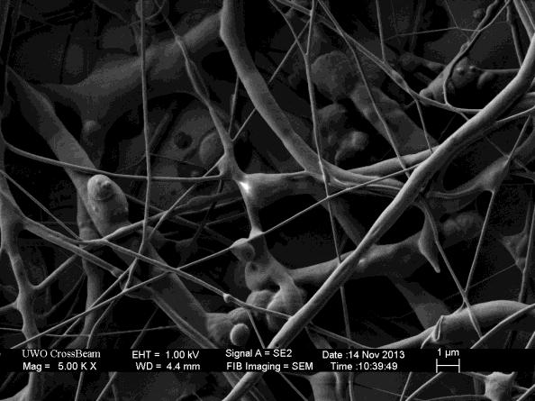
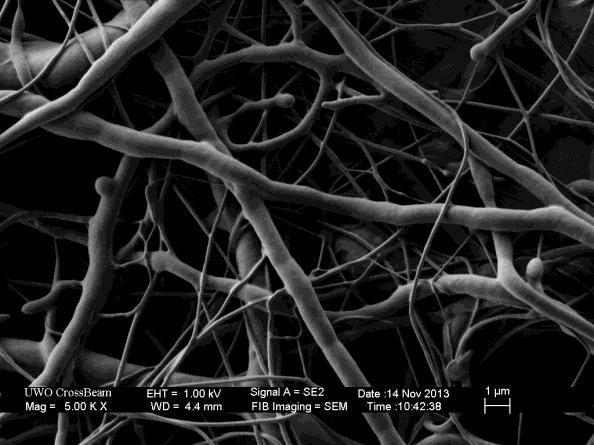


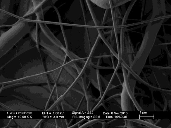

120 106


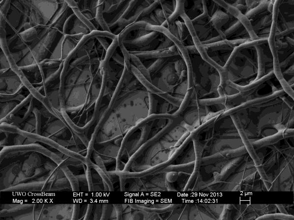
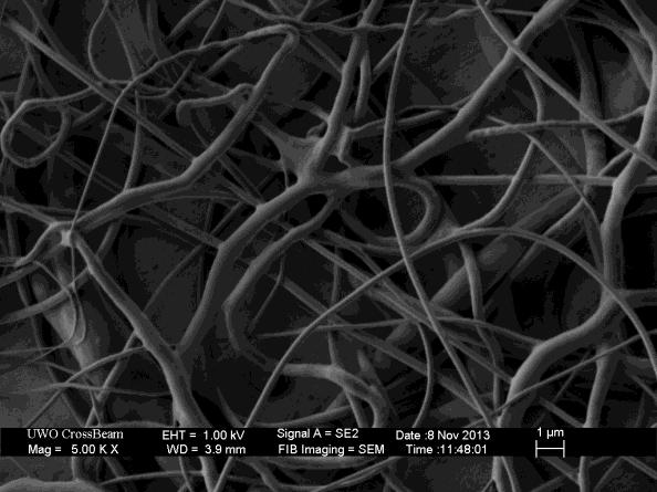
121 30% RH 107
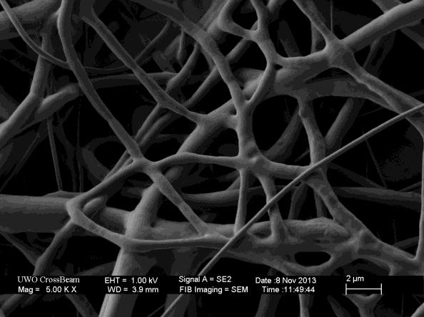
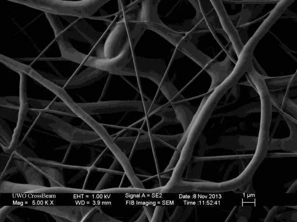
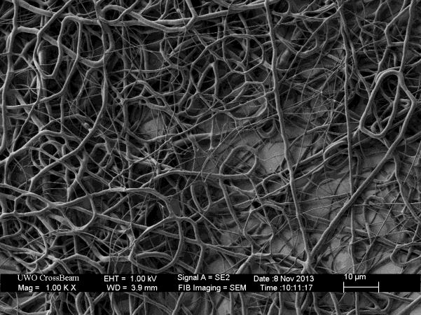
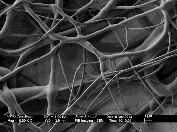
122 108

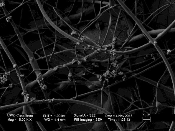
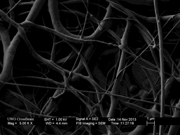
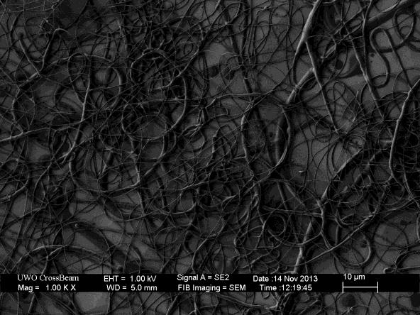


123 25% RH 109


124 20% RH 110


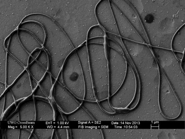

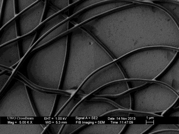
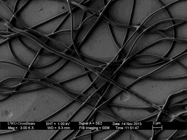
125 111
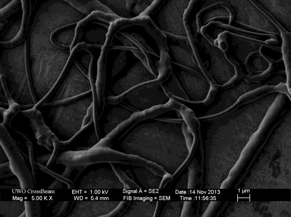
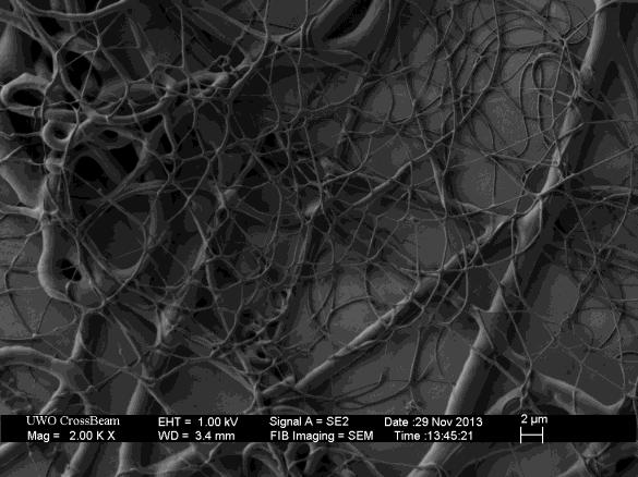
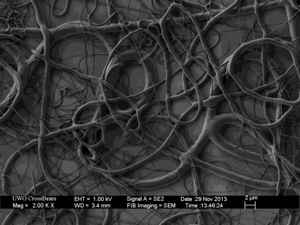
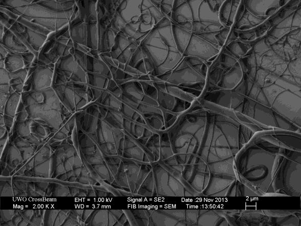
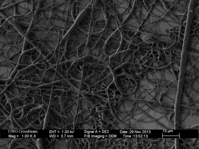
126 112


127 Appendix C: Confocal Images 40% RH 113

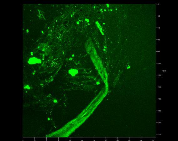

128 30% RH 114
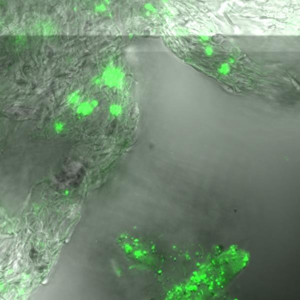

129 115


130 25% RH 116

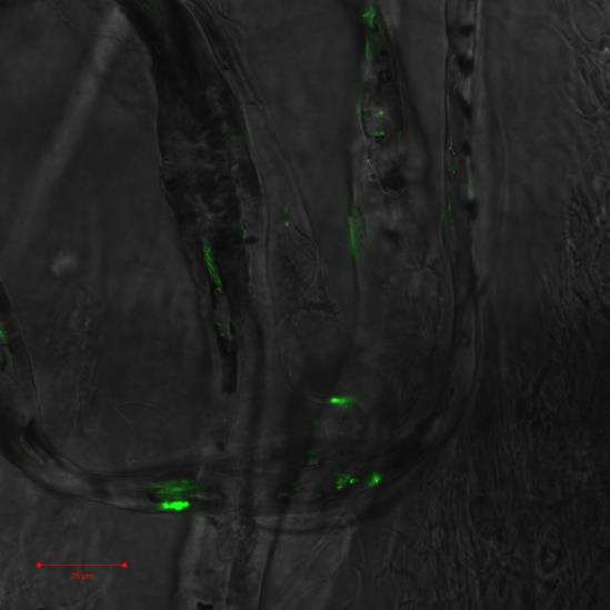
131 20% RH 117
Electrospinning of Core-shell Collagen Nanofibers
 Western University Scholarship@Western Electronic Thesis and Dissertation Repository August 2013 Electrospinning of Core-shell Collagen Nanofibers Ying Li The University of Western Ontario Supervisor Dr.
Electrospun collagen fibers for tissue regeneration applications
 Western University Scholarship@Western Electronic Thesis and Dissertation Repository October 2018 Electrospun collagen fibers for tissue regeneration applications Ying Li The University of Western Ontario
Prof. Steven S. Saliterman. Department of Biomedical Engineering, University of Minnesota
 Department of Biomedical Engineering, University of Minnesota http://saliterman.umn.edu/ Mimicking the fibrillar structure of the extracellular matrix is important for scaffolds. Clinical trails to date
Nanomechanics of Electrospun Nanofibres for Tissue Engineering of the Tympanic Membrane
 Western University Scholarship@Western Electronic Thesis and Dissertation Repository December 2012 Nanomechanics of Electrospun Nanofibres for Tissue Engineering of the Tympanic Membrane Sara Makaremi
Artificial blood vessels
 Artificial blood vessels S. Swaminathan Director Centre for Nanotechnology & Advanced Biomaterials School of Chemical & Biotechnology SASTRA University Thanjavur 613 401 Tamil Nadu Joint Initiative of
ELECTROSPINNING OF POLYACRYLONITRILE NANOFIBERS. by Sandip Basu
 ELECTROSPINNING OF POLYACRYLONITRILE NANOFIBERS by Sandip Basu Department of Textile Technology Submitted in fulfilment of the requirements of the degree of Doctor of Philosophy to the Indian Institute
INFLUENCE OF THE SURFACE MORPHOLOGY AT SPECIFIC SURFACE AREA OF MICROFIBRES MADE FROM POLY (L-LACTIDE) MACAJOVÁ Eva
 MACAJOVÁ Eva") INFLUENCE OF THE SURFACE MORPHOLOGY AT SPECIFIC SURFACE AREA OF MICROFIBRES MADE FROM POLY (L-LACTIDE) MACAJOVÁ Eva Department of Material Science, Technical University of Liberec, Liberec, Czech Republic,
INFLUENCE OF THE SURFACE MORPHOLOGY AT SPECIFIC SURFACE AREA OF MICROFIBRES MADE FROM POLY (L-LACTIDE) MACAJOVÁ Eva Department of Material Science, Technical University of Liberec, Liberec, Czech Republic,
Quantitative analysis of human mesenchymal stem cell alignment by electrospun polymer nanofibrous scaffolds
 Quantitative analysis of human mesenchymal stem cell alignment by electrospun polymer nanofibrous scaffolds Nicole Green 1, Joel Wise 2, Dr. Michael Cho 2, Dr. Constantine Megaridis 3 1 Department of Chemical
Centrifugal spinning of nanofiber webs - A parameter study of a novel spinning process
 Centrifugal spinning of nanofiber webs - A parameter study of a novel spinning process Jonas Engström Senior scientist at Swerea IVF. Finished his PhD in 2006 with a thesis titled Functional compolymers
Effect of Target Shapes on Distribution of Polyacrylonitrile Nanofibers Prepared by Electrospinning Process
 109 Effect of Target Shapes on Distribution of Polyacrylonitrile Nanofibers Prepared by Electrospinning Process Bussarin Ksapabutr *, Chaowat Waikru and Manop Panapoy Department of Materials Science and
Comparison between Electrospun and Bubbfil-spun Polyether Sulfone Fibers
 ISSN 1517-7076 artigo 11564 pp.363-369, 2014 Comparison between Electrospun and Bubbfil-spun Polyether Sulfone Fibers Ya Li 1,2, Rou-xi Chen 1,2, Fu-Juan Liu 1,2 1 National Engineering Laboratory for Modern
Bioreactors in tissue engineering
 Bioreactors in tissue engineering S. Swaminathan Director Centre for Nanotechnology & Advanced Biomaterials School of Chemical & Biotechnology SASTRA University Thanjavur 613 401 Tamil Nadu Joint Initiative
Catherine G. Reyes, Anshul Sharma and Jan P.F. Lagerwall. July 18, Complete description of experimental details
 Non-electronic gas sensor from electrospun mats of liquid crystal core fibers for detecting volatile organic compounds at room temperature: Supplemental Online Material Catherine G. Reyes, Anshul Sharma
Versatile Core-Sheath Biofibers using Coaxial Electrospinning
 Mater. Res. Soc. Symp. Proc. Vol. 1094 2008 Materials Research Society 1094-DD06-02 Versatile Core-Sheath Biofibers using Coaxial Electrospinning Daewoo Han 1, Steven T. Boyce 2, and Andrew J. Steckl 1
NEXT GENERATION ECM-BASED ALLOGRAFT TECHNOLOGY:
 NEXT GENERATION ECM-BASED ALLOGRAFT TECHNOLOGY: Potent biological scaffolds strategically control stem cell fate and function, allowing our allografts to harness the regenerative potential of patient s
Supporting Information
 Supporting Information Novel Interwoven Polymer Composites via Dual- Electrospinning with Shape Memory/Self-healing Properties Jaimee M. Robertson, Hossein Birjandi Nejad, Patrick T. Mather* Syracuse Biomaterials
WOVEN FABRIC CREATED BY NANOFIBROUS YARNS
 WOVEN FABRIC CREATED BY NANOFIBROUS YARNS Jiří Chvojka a, Martina Pokorná b, David Lukáš a a Technical University of Liberec, Faculty of Textile Engineering, Department of Nonwovens, Studentska 2., 461
Manipulation of the electric field of electrospinning system to produce polyacrylonitrile nanofiber yarn
 Manipulation of the electric field of electrospinning system to produce polyacrylonitrile nanofiber yarn Date Submitted 22 December 2005, Date Accepted 15 June 2006 F. Dabirian 1, Y. Hosseini 2 and S.
FLUIDNATEK CUTTING EDGE ELECTROSPINNING & ELECTROSPRAYING DEVICES
 FLUIDNATEK CUTTING EDGE ELECTROSPINNING & ELECTROSPRAYING DEVICES by THE FLUIDNATEK TOOLS we create the future USE CASES FLUIDNATEK Lab Tools are research instruments designed for the fabrication of small
Mechanical Characterization and Stimulation Solutions for Biomaterials
 Mechanical Characterization and Stimulation Solutions for Biomaterials BioDynamic Instruments Biomaterials and Tissue Characterization Application Examples Bone Bending Creep Test Clinical Need: Understand
Lecture Outline. History. Purpose? Func:on of Bioscaffolds. Extracellular Matrix (ECM) 12/08/15
 12/08/15") Associate Professor Rod Dilley Dr Rob Marano Ear Sciences Centre School of Surgery Harry Perkins Research Building 4 th Floor Lecture Outline History Purpose Functions Properties Approaches to bioscaffold
Associate Professor Rod Dilley Dr Rob Marano Ear Sciences Centre School of Surgery Harry Perkins Research Building 4 th Floor Lecture Outline History Purpose Functions Properties Approaches to bioscaffold
Electrospinning and Porosity Measurements of Nylon- 6/Poly(ethylene oxide) Blended Nonwovens
 Blended Nonwovens") Electrospinning and Porosity Measurements of Nylon- 6/Poly(ethylene oxide) Blended Nonwovens Margaret W. Frey, Ph.D. 1 and Lei Li, Ph.D. 1 1 Department of Textiles and Apparel, Cornell University, Ithaca
Electrospinning and Porosity Measurements of Nylon- 6/Poly(ethylene oxide) Blended Nonwovens Margaret W. Frey, Ph.D. 1 and Lei Li, Ph.D. 1 1 Department of Textiles and Apparel, Cornell University, Ithaca
Hydrodynamics of Drop Impact and Spray Cooling through Nanofiber Mats
 Hydrodynamics of Drop Impact and Spray Cooling through Nanofiber Mats Y. Chan Department of Chemical Engineering, University of Massachusetts Amherst, Amherst, MA 01003 F. Charbel Department of Mechanical
Micro/Nano Mechanical Systems Lab Class#16
 Microsystems Laboratory Micro/Nano Mechanical Systems Lab Class#16 Liwei Lin Professor, Dept. of Mechanical Engineering Co-Director, Berkeley Sensor and Actuator Center The University of California, Berkeley,
Electrospinning and Polarization of PVDF Fiber Mats for Adsorption of NaCl
 The University of Akron IdeaExchange@UAkron Honors Research Projects The Dr. Gary B. and Pamela S. Williams Honors College Electrospinning and Polarization of PVDF Fiber Mats for Adsorption of NaCl Michael
CNT Reinforced Nanocomposite Fiber Fabrication for Undergraduate Students
 CNT Reinforced Nanocomposite Fiber Fabrication for Undergraduate Students 1 Asmatulu, R., 1 Khan, W., and 2 Yildirim, M.B. Abatract 1 Department of Mechanical Engineering, Wichita State University 1845
Articular Cartilage Engineering Using Human Mesenchymal Stem Cells and Nanostructured Biomaterials
 Articular Cartilage Engineering Using Human Mesenchymal Stem Cells and Nanostructured Biomaterials REU Participant: Nicole Green 1 Advisors: Joel Wise 2, Dr. Michael Cho 2, Dr. Constantine Megaridis 3
Polymeric hydrogels are of special importance in polymeric biomaterials because of
 POLYMERIC HYDROGELS Polymeric hydrogels are of special importance in polymeric biomaterials because of their favorable biocompatibility. Hydrogels are cross-linked macromolecular networks formed by hydrophilic
Electrospun Nanofibers as Separators in Li-ion in Batteries. Dr. Cagri Tekmen Elmarco Ltd., Sekido, Tama, Sekido Bld 4F, Tokyo , Japan
 Electrospun Nanofibers as Separators in Li-ion in Batteries Dr. Cagri Tekmen Elmarco Ltd., 3-4-1 Sekido, Tama, Sekido Bld 4F, Tokyo 206-0011, Japan 1. Introduction One-dimensional (1D) nanostructures -having
ELECTROSPUN NANOFIBER PROCESS CONTROL
 CELLULOSE CHEMISTRY AND TECHNOLOGY Received April 26, 2010 ELECTROSPUN NANOFIBER PROCESS CONTROL University of Guilan, P.O. Box 3756, Rasht, Iran Fiber diameter is an important structural characteristic
Supporting Information
 Electronic Supplementary Material (ESI) for Nanoscale. This journal is The Royal Society of Chemistry 2018 Supporting Information High performance electronic devices based on nanofibers via crosslinking
Controlled Microassembly and Transport of Nano- and Micro-components using Bacteria. Sylvain Martel
 Controlled Microassembly and Transport of Nano- and Micro-components using Bacteria Sylvain Martel NanoRobotics Laboratory Department of Computer and Software Engineering, and Institute of Biomedical Engineering
E-TEAM. Characterisation of Polyamide 6 Nanofibres. European Masters in Textile Engineering. Özgür Ceylan. Promoter: Karen De Clerck.
 Association of Universities for Textiles E-TEAM European Masters in Textile Engineering Characterisation of Polyamide 6 Nanofibres Özgür Ceylan Promoter: Karen De Clerck Ghent University Academic year:
MORPHOLOGY CONTROLLED ELECTROSPUN POLY(VINYL PYRROLIDONE) FIBERS: EFFECTS OF ORGANIC SOLVENT AND RELATIVE HUMIDITY
 FIBERS: EFFECTS OF ORGANIC SOLVENT AND RELATIVE HUMIDITY") Journal of Materials Science and Engineering with Advanced Technology Volume 2, Number 1, 2010, Pages 97-112 MORPHOLOGY CONTROLLED ELECTROSPUN POLY(VINYL PYRROLIDONE) FIBERS: EFFECTS OF ORGANIC SOLVENT
Journal of Materials Science and Engineering with Advanced Technology Volume 2, Number 1, 2010, Pages 97-112 MORPHOLOGY CONTROLLED ELECTROSPUN POLY(VINYL PYRROLIDONE) FIBERS: EFFECTS OF ORGANIC SOLVENT
Design of scaffolds with computer assistance
 Modelling in Medicine and Biology VII 157 Design of scaffolds with computer assistance H. A. Almeida 1, P. J. Bártolo 1 & J. C. Ferreira 2 1 Centre for Rapid and Sustainable Product Development CDRsp,
Chapter 8. Comparison of static vs dynamic culture
 Chapter 8 Comparison of static vs dynamic culture 8.1. Literature Review Articular cartilage is a load-bearing connective tissue in which its functions not only transmitting the compressive joint loads
DRUG DELIVERY PARTICLES FABRICATED USING THE ELECTROHYDRODYNAMIC ATOMIZATION (EHDA) METHOD
 METHOD") ABSTRACT DRUG DELIVERY PARTICLES FABRICATED USING THE ELECTROHYDRODYNAMIC ATOMIZATION (EHDA) METHOD YEO YING QIAN and WANG CHI-HWA Department of Chemical and Biomolecular Engineering National University
ABSTRACT DRUG DELIVERY PARTICLES FABRICATED USING THE ELECTROHYDRODYNAMIC ATOMIZATION (EHDA) METHOD YEO YING QIAN and WANG CHI-HWA Department of Chemical and Biomolecular Engineering National University
The Preparation of C/Ni Composite Nanofibers with Pores by Coaxial Electrospinning
 2016 International Conference on Intelligent Manufacturing and Materials (ICIMM 2016) ISBN: 978-1-60595-363-2 The Preparation of C/Ni Composite Nanofibers with Pores by Coaxial Electrospinning Yiqiang
Aalborg University 1
 1 Aalborg University Electrospinning of fibre embedded cells as scaffolds for muscle regeneration Title: Electrospinning of fibre embedded cells as scaffolds for muscle regeneration Project student: Laura
Electret Polyvinylidene Fluoride Nanofibers Hybridized by Polytetrafluoroethylene Nanoparticles for High-Efficiency Air Filtration
 Supporting Information Electret Polyvinylidene Fluoride Nanofibers Hybridized by Polytetrafluoroethylene Nanoparticles for High-Efficiency Air Filtration Shan Wang,,, Xinglei Zhao,,, Xia Yin,*,, Jianyong
PRINCIPLES AND PRACTICE OF TISSUE ENGNEERING:
 Harvard-MIT Division of Health Sciences and Technology HST.535: Principles and Practice of Tissue Engineering Instructor: Myron Spector Massachusetts Institute of Technology Harvard Medical School Brigham
A Belt-like superfine film fabricated by bubble-electrospinning Hao Dou 1,a, Bao-qi Zuo 1
 Advanced Materials Research Online: 2013-11-21 ISSN: 1662-8985, Vol. 843, pp 82-85 doi:10.4028/www.scientific.net/amr.843.82 2014 Trans Tech Publications, Switzerland A Belt-like superfine film fabricated
Chapter 3: Powders Production and Characterization
 Chapter 3: Powders Production and Characterization Course Objective... To introduce selective powder production processes and characterization methods. This course will help you : To understand properties
Tissue Engineering: The art of growing body parts. Robby Bowles, Ph.D Cornell University
 Tissue Engineering: The art of growing body parts Robby Bowles, Ph.D Cornell University What is Tissue Engineering? What is Tissue Engineering? TE is an interdisciplinary field that applies the principles
Investigation into Electrospun LaMnO 3 Nanofibres
 Universities Research Journal 2011, Vol. 4, No. 4 Investigation into Electrospun LaMnO 3 Nanofibres Zin Min Myat 1, Than Than Win 2 and Yin Maung Maung 3 Abstract This paper aims to prepare nanofibres
Development of Polymer Based Nanocomposite using Electrospinning for Sound Absorption and Isolation
 University of Ontario Institute of Technology Faculty of Engineering and Applied Science Development of Polymer Based Nanocomposite using Electrospinning for Sound Absorption and Isolation Submitted By:
1) Determining the best cell sources and scaffold materials for TEHV development.
 Determining the best cell sources and scaffold materials for TEHV development.") Broadly speaking, my primary research interests focus on the development and application of methodologies that can be employed in the basic understanding and optimization of tissue engineered heart valves
Broadly speaking, my primary research interests focus on the development and application of methodologies that can be employed in the basic understanding and optimization of tissue engineered heart valves
Pittsburgh Tissue Engineering Initiative Annual Progress Report: 2011 Formula Grant
 Pittsburgh Tissue Engineering Initiative Annual Progress Report: 2011 Formula Grant Reporting Period July 1, 2012 December 31, 2012 Formula Grant Overview The Pittsburgh Tissue Engineering Initiative received
COMPARISON OF NANOPOROUS SCAFFOLDS MANUFACTURED BY ELECTROSPINNING AND NANOFIBRILLAR COMPOSITE CONCEPT
 18 TH INTERNATIONAL CONFERENCE ON COMPOSITE MATERIALS COMPARISON OF NANOPOROUS SCAFFOLDS MANUFACTURED BY ELECTROSPINNING AND NANOFIBRILLAR COMPOSITE CONCEPT S. T. C. Lin 1 *, D. Bhattacharyya 1, S. Fakirov
Chapter 2 Scaffold Fabrication Protocols
 Chapter 2 Scaffold Fabrication Protocols Abstract Development of scaffolds in tissue engineering applications is growing in a fast pace. Scaffolds play a pivotal role in scaffold-based tissue engineering.
NanoFabrication Systems DPN. Nanofabrication Systems. A complete line of instruments and tools for micro and nanopatterning applications
 DPN Nanofabrication Systems A complete line of instruments and tools for micro and nanopatterning applications DPN Nanofabrication Systems A complete line of instruments and tools for micro and nanopatterning
Ying Li1, Prof. Wankei Wan1, 2 1Biomedical Engineering Graduate Program 2Department of Chemical and Biochemical Engineering
 π NanoWestern Issue 2 2016 Electrospun Collagen Scaffold for Tympanic Membrane Perforations Ying Li1, Prof. Wankei Wan1, 2 1Biomedical Engineering Graduate Program 2Department of Chemical and Biochemical
Affinity. A Paradigm Shift in Skeletal Reconstruction
 Affinity A Paradigm Shift in Skeletal Reconstruction INTRODUCING TRS AFFINITY SKELETAL RECONSTRUCTION BREAKTHROUGH Tissue Regeneration Systems (TRS ) is a start-up medical device company commercializing
BEH.462/3.962J Molecular Principles of Biomaterials Spring 2003
 Lecture 6: Biodegradable Polymers for Tissue Engineering Last time: Today: enzymatic degradation of solid polymers Engineering biological recognition of polymers Designing polymers for tissue engineering
Biomedical Engineering 3D BIOPRINTING OF SILK FOR CELLULAR APPLICATIONS. Martina Ravizza
 Biomedical Engineering 3D BIOPRINTING OF SILK FOR CELLULAR APPLICATIONS Martina Ravizza Supervisor: Prof. Ferdinando Auricchio Correlator: Dott. Michele Conti Sericina Fibroina Academic year 2014/2015
Regenerez : A Next-Generation Material for Functional Bioresorbable Coatings. by Carissa Smoot and Jeremy Harris, Ph.D, Secant Medical, Inc.
 Regenerez : A Next-Generation Material for Functional Bioresorbable Coatings by Carissa Smoot and Jeremy Harris, Ph.D, Secant Medical, Inc. Coatings consisting of natural and synthetic origin play an important
FABRICATION OF LAYER-BY-LAYER ELECTROSPUN COMPOSITE MEMBRANES BASED ON POLYLACTIC ACID (PLA) AND POLY (CAPROLACTONE) (PCL)/CHITOSAN
 AND POLY (CAPROLACTONE) (PCL)/CHITOSAN") FABRICATION OF LAYER-BY-LAYER ELECTROSPUN COMPOSITE MEMBRANES BASED ON POLYLACTIC ACID (PLA) AND POLY (CAPROLACTONE) (PCL)/CHITOSAN Choi Yee Foong 1 and Naznin Sultana 1, 2 1 Faculty of Biosciences and
FABRICATION OF LAYER-BY-LAYER ELECTROSPUN COMPOSITE MEMBRANES BASED ON POLYLACTIC ACID (PLA) AND POLY (CAPROLACTONE) (PCL)/CHITOSAN Choi Yee Foong 1 and Naznin Sultana 1, 2 1 Faculty of Biosciences and
Direct Electrospinning Writing
 2-26-2018 Biofabrication Workshop Biomaterials Lab and Center for Engineering Complex Tissues Anthony J. Melchiorri, Ph.D. Associate Director, Biomaterials Lab Rice University Hochleitner, et al. Biofabrication.
New Breakthroughs in Water Purification
 Fiber Nanofiber d 300nm Functionalized soft matter: Using plastics, instead of expensive ceramic materials Nanofiber Technology & Molecular Engineering for Environment: Application to Water Purification
Nanodiamond-Polymer Composite Fibers and Coatings
 Nanodiamond-Polymer Composite Fibers and Coatings Yury Gogotsi et al. A.J. Drexel Nanotechnology Institute and Department of Materials Science and Engineering Drexel University, Philadelphia, Pennsylvania
Property of electrospinning silk fibroin nanofibers prepared by different dissolved methods
 Property of electrospinning silk fibroin nanofibers prepared by different dissolved methods Huiying WU a, *, Yan ZHOU b, Ping YO c, Maomao DING D Suzhou Institute of Trade & Commerce Suzhou 215009 China
nanoprecipitation mpeg-pla 2 nd Emulsion mpeg-pla in DCM
 THERAPEUTIC NANOTECHNOLOGY LAB MODULE Location: BioNano Lab, 3119 Micro and Nanotechnology Laboratory (MNTL) Instructor: Jianjun Cheng, Assistant Professor of Materials Science and Engineering Lab Assistants:
Seevix s SVXgro: A Spidersilk Scaffold for Tissue Engineering
 Seevix s gro: A Spidersilk Scaffold for Tissue Engineering Spider dragline silk exhibits extraordinary mechanical properties that combine strength with elasticity, resulting in a toughness exceeding that
Supporting Information
 Supporting Information In situ Active Poling of Nanofibers Network for Gigantically Enhanced Particulate Filtration Chun Xiao Li,, Shuang Yang Kuang,, Yang Hui Chen,, Zhong Lin Wang,,,#, Congju Li, and
Stem cells and tissue engineering
 Stem cells and tissue engineering S. Swaminathan Director Centre for Nanotechnology & Advanced Biomaterials School of Chemical & Biotechnology SASTRA University Thanjavur 613 401 Tamil Nadu Joint Initiative
A review of Dr. Dinakar Golla s clinical research with AdMatrix surgical grafts for soft tissue repair
 TEAMeffort: Using aggressive surgical techniques in combination with AdMatrix (Lattice Biologics acellular dermal scaffold product) to heal difficult and persistent wounds A review of Dr. Dinakar Golla
ChE 125. Principles of Bioengineering
 ChE 125 Principles of Bioengineering ChE 125 Instructor: Prof. Samir Mitragotri Room 3349, Engineering II Email: samir@engineering.ucsb.edu Office Hours: Tuesday 1-2 pm Teaching Assistant: Aaron Anselmo
Available from Deakin Research Online:
 This is the published version: Huang, Chen, Niu, Haitao, Wu, Jinglei, Ke, Qinfei, Mo, Xiumei and Lin, Tong 2012, Needleless eletrospinning of polystyrene fibers with an oriented surface line texture, Journal
Supporting Information for Sub-1 nm Nanowire Based Superlattice Showing High Strength and Low Modulus Huiling Liu,, Qihua Gong, Yonghai Yue,*,
 Supporting Information for Sub-1 nm Nanowire Based Superlattice Showing High Strength and Low Modulus Huiling Liu,, Qihua Gong, Yonghai Yue,*, Lin Guo*, and Xun Wang*, *To whom correspondence should be
Fiber spinning of biopolymers containing nanowhiskers : Possibilities and challenges
 Fiber spinning of biopolymers containing nanowhiskers : Possibilities and challenges Aji P. Mathew and Kristiina Oksman Wood and Bionanocomposites, Division of Materials Science Luleå University of Technology,
A MATHEMATICAL MODEL OF META-ARAMID FIBRID FORMATION
 THERMAL SCIENCE, Year 2017, Vol. 21, No. 4, pp. 1651-1655 1651 A MATHEMATICAL MODEL OF META-ARAMID FIBRID FORMATION by Li-Rong YAO *, Xiao-Juan LI, Ye-Qun JIANG, and Shan-Qing XU School of Textile and
BE.430/2.795//6.561/10.539/HST.544. Final Exam. Handed out: Monday, Dec. 6, 2004 Due: Thursday, Dec. 9 by 5pm
 BE.430/2.795//6.561/10.539/HST.544 Final Exam Handed out: Monday, Dec. 6, 2004 Due: Thursday, Dec. 9 by 5pm Problem 1 (30 %) ALG Notes Problem 2.6.3 Parts a f (not g) (Page 199) Problem 2 (35 %) When patients
Polyacrylonitrile nanofibre yarn; electrospinning and their post-drawing behaviour
 Polyacrylonitrile nanofibre yarn; electrospinning and their post-drawing behaviour by Zhigang Xie (B. Eng) Submitted in fulfilment of the requirements of the degree of Master of Philosophy Deakin University
ABSTRACT. Electrospinning is a technique that uses electric field to produced nanofibers in the range of
 ABSTRACT NANDGAONKAR, AVINAV GHANASHYAM. Electrospinning of Chitosan and its Correlation with Degree of Deacetylation and Rheological Property. (Under the direction of Dr. Wendy E. Krause, TECS.) Electrospinning
SUPPLEMENTARY INFORMATION
 Supplementary Methods Natural spider silk. The orb-web of spider (Uloborus walckenaerius) was captured in Beijing, China. There are two types of silk in spider web, i.e., capture silk and radial silk.
Lab Module 7: Cell Adhesion
 Lab Module 7: Cell Adhesion Tissues are made of cells and materials secreted by cells that occupy the spaces between the individual cells. This material outside of cells is called the Extracellular Matrix
Effect of Nanofiber Morphology on PVDF Air Filter Performance
 The University of Akron IdeaExchange@UAkron Honors Research Projects The Dr. Gary B. and Pamela S. Williams Honors College Spring 2015 Effect of Nanofiber Morphology on PVDF Air Filter Performance Andrew
Introduction to Cell/ Biomaterial Engineering
 Introduction to Cell/ Biomaterial Engineering Module 3, Lecture 1! 20.109 Spring 2011! Topics for Lecture 1 Introduction to tissue engineering! motivation! basic principles + examples! Introduction to
Negatively charged microspheres provide an additional surface for cell attachment leading to proliferation, tissue regeneration and wound healing
 Negatively charged microspheres provide an additional surface for cell attachment leading to proliferation, tissue regeneration and wound healing Authors: Correa LG, Peter R, Clerici G, Ritter V. 2017
3D MICRO-NANO FIBROUS SCAFFOLD PREPARED BY MELTBLOWN IN COMBINATION WITH ELECTROSPINNING FOR THE BONE TISSUE ENGENEERING
 3D MICRO-NANO FIBROUS SCAFFOLD PREPARED BY MELTBLOWN IN COMBINATION WITH ELECTROSPINNING FOR THE BONE TISSUE ENGENEERING Jakub ERBEN a, Kateřina PILAŘOVÁ a, Filip SANETRNÍK a, Jiří CHVOJKA a, Věra JENČOVÁ
Polymer Nanofiber-Guided Uniform Lithium Deposition for Battery Electrodes
 Polymer Nanofiber-Guided Uniform Lithium Deposition for Battery Electrodes Zheng Liang, Guangyuan Zheng, Chong Liu, Nian Liu, Weiyang Li, Kai Yan, Hongbin Yao, Po-Chun Hsu, Steven Chu, and Yi Cui *,, Department
Applications of self-assembling peptides in controlled drug delivery
 Applications of self-assembling peptides in controlled drug delivery Sotirios Koutsopoulos, Ph.D. Problems associated with drug administration Drug concentration in blood C toxic C effective Time 1 The
Edge Effects in Single- and Multi-Layer Drying Coatings
 Edge Effects in Single- and Multi-Layer Drying Coatings H. Radhakrishnan and L. E. Scriven Department of Chemical Engineering & Materials Science University of Minnesota Minneapolis, MN 55455 Presented
White Paper: Textile Engineered Tissue Scaffolds Offer Advances in Hollow Organ Regenerations. Peter D. Gabriele Director, Emerging Technology
 White Paper: Textile Engineered Tissue Scaffolds Offer Advances in Hollow Organ Regenerations Peter D. Gabriele Director, Emerging Technology Regenerative medicine (RM) holds the potential to address some
ISTINYE UNIVERSITY INSTITUTE OF HEALTH SCIENCES DEPARTMENT OF STEM CELL AND TISSUE ENGINEERING (THESIS) COURSE DESCRIPTIONS
 COURSE DESCRIPTIONS") ISTINYE UNIVERSITY INSTITUTE OF HEALTH SCIENCES DEPARTMENT OF STEM CELL AND TISSUE ENGINEERING (THESIS) COURSE DESCRIPTIONS 1 st SEMESTER Adult Stem Cell Biology 5 ECTS In this course, the characteristics
ISTINYE UNIVERSITY INSTITUTE OF HEALTH SCIENCES DEPARTMENT OF STEM CELL AND TISSUE ENGINEERING (THESIS) COURSE DESCRIPTIONS 1 st SEMESTER Adult Stem Cell Biology 5 ECTS In this course, the characteristics
Supplementary Figure S1. Swelling and mechanical properties as a function of the PS-b- PAA block copolymer composition. a, Swelling kinetics of PAA
 Supplementary Figure S1. Swelling and mechanical properties as a function of the PS-b- PAA block copolymer composition. a, Swelling kinetics of PAA homopolymer and PS-b-PAAs (4 mm disc with 1 mm thickness)
Polymers against Microorganisms
 Polymers against Microorganisms Juan Rodríguez-Hernández Polymers against Microorganisms On the Race to Efficient Antimicrobial Materials Juan Rodríguez-Hernández Institute of Polymer Science & Technology
UNIT CELL PROCESSES UNDERLYING TISSUE ENGINEERING AND REGENERATIVE MEDICINE
 Massachusetts Institute of Technology Harvard Medical School Brigham and Women s Hospital VA Boston Healthcare System 2.79J/3.96J/20.441/HST522J UNIT CELL PROCESSES UNDERLYING TISSUE ENGINEERING AND REGENERATIVE
PREPARATION AND CHARACTERIZATION OF MULTI-LAYER BIODEGRADABLE NANOFIBERS BY COAXIAL ELECTROSPINNING AND THEIR POTENTIAL FOR TISSUE ENGINEERING
 PREPARATION AND CHARACTERIZATION OF MULTI-LAYER BIODEGRADABLE NANOFIBERS BY COAXIAL ELECTROSPINNING AND THEIR POTENTIAL FOR TISSUE ENGINEERING by Wenwen Liu A dissertation submitted to the Faculty of the
Control of Inter-fiber Fusing for Nanofiber Webs via Electrospinning
 Control of Inter-fiber Fusing for Nanofiber Webs via Electrospinning Bharath K. Raghavan, Ph.D., Douglas W. Coffin Miami University, Oxford, Ohio UNITED STATES Correspondence to: Douglas W. Coffin email:
Preparation of Electrospun Piezoelectric Polyvinylidene Fluoride Nanofibers
 Preparation of Electrospun Piezoelectric Polyvinylidene Fluoride Nanofibers Jerrell Walker, Electrical Engineering student at the University of Pennsylvania, SUNFEST Fellow Dr. Jorge J. Santiago - Aviles,
5. INVESTIGATION OF POROSITY IN THE PASTILLES
 5. INVESTIGATION OF POROSITY IN THE PASTILLES 5.1. Introduction Many different types of controlled dosage forms have been developed to improve clinical efficiency of drug and patient compliance. In vivo
Introduction to Polymer-Dispersed Liquid Crystals
 Introduction to Polymer-Dispersed Liquid Crystals Polymer-dispersed liquid crystals (PDLCs) are a relatively new class of materials that hold promise for many applications ranging from switchable windows
EDGE CHIPPING RESISTANCE USING MACROINDENTATION TESTING
 EDGE CHIPPING RESISTANCE USING MACROINDENTATION TESTING Prepared by Ali Mansouri 6 Morgan, Ste156, Irvine CA 92618 P: 949.461.9292 F: 949.461.9232 nanovea.com Today's standard for tomorrow's materials.
Surface Characterization of Biomaterials
 Surface Characterization of Biomaterials Biomaterials are determined The desire for well-being and long life expectancy goes hand in-hand with the use of non-viable materials to conserve health. 2000 years
INVESTIGATION OF HIGHLY POROUS POLY(Ε-CAPROLACTONE)
") szerzoi_jav_005_036.qxd 2008.06.20. 16:00 Page 30 INVESTIGATION OF HIGHLY POROUS POLY(Ε-CAPROLACTONE) SCAFFOLDS László Oláh 1, Lajos Borbás 2, Tibor Czigány 3 1 Polymer Competence Center Leoben GmbH 2
szerzoi_jav_005_036.qxd 2008.06.20. 16:00 Page 30 INVESTIGATION OF HIGHLY POROUS POLY(Ε-CAPROLACTONE) SCAFFOLDS László Oláh 1, Lajos Borbás 2, Tibor Czigány 3 1 Polymer Competence Center Leoben GmbH 2
3D Transfection System
 3D Transfection System Why 3D Technology? Introduction to Three Dimensional (3D) Cell Culture The goal of three-dimensional (3D) cell culture is to eliminate the stress and artificial responses cells experience
Biomedical applications of inkjet printing at the UoN
 Biomedical applications of inkjet printing at the UoN Content Why Material Jetting? Printability requirement Material Jetting at UoN Polycaprolactone: inkjet printing of bioresorbable material 3D printing
Mechano-dependent Biosynthetic Response of Micro-integrated Cells in Elastomeric Scaffolds
 Mechano-dependent Biosynthetic Response of Micro-integrated Cells in Elastomeric Scaffolds Lauren Anderson 1,2, John Stella 3, and Dr. Michael Sacks 3 1 Bioengineering and Bioinformatics Summer Institute,
Thermoresponsive Membranes from Electrospun. Mats with Switchable Wettability for Efficient
 Thermoresponsive Membranes from Electrospun Mats with Switchable Wettability for Efficient Oil/Water Separations Yan Liu, a,b Sinem Tas, b Kaihuan Zhang, b, Wiebe M. de Vos, c Jinghong Ma, a,* and G. Julius