Repairs to BEQs 833 and 834
|
|
|
- Piers Nigel Wheeler
- 6 years ago
- Views:
Transcription
1 eprojects Number: Construction Contract Number: N D-XXXX Appropriation: Special Projects RM / Repairs to BEQs 833 and 834 At the Naval Station, Great Lakes, Illinois (Job Order Number 366AA0) SUBMITTED BY: Public Works Department, Great Lakes 2625 Ray Street; Building 2016 Great Lakes, IL PREPARED BY: Architectural: Structural: Mechanical: Electrical: Krishna Kumar, R.A. John Nanak, S.E. Miroslav Sapozhnikov, P.E. Eddie Tumlos Lead Engineer: John Nanak, S.E. Date: June 29, 2012 APPROVED BY: David Marasco, P.E.: PWDGL Project Management/Engineering Branch Manager LCDR Robert Kleinman: FEAD Division Branch Manager For Commander, NAVFAC Mid-West: Date: July 16, 2012 FOR RELEASE JULY 16, 2012
2 Repairs to Bachelor Enlisted Quarters eprojects Number Buildings 833 & 834, Great Lakes, IL 1.0 Table of Contents (RFP Parts 2-6) 1. PART 2 GENERAL REQUIREMENTS WORK RESTRICTIONS FOR DESIGN-BUILD PRICE AND PAYMENT PROCEDURES FOR DESIGN-BUILD ADMINISTRATIVE REQUIREMENTS FOR DESIGN-BUILD POST AWARD MEETINGS NETWORK ANALYSIS SCHEDULES (NAS) FOR DESIGN-BUILD CONSTRUCTION SUBMITTAL PROCEDURES DESIGN SUBMITTAL PROCEDURES GOVERNMENT SAFETY REQUIREMENTS FOR DESIGN-BUILD DESIGN AND CONSTRUCTION QUALITY CONTROL TEMPORARY FACILITIES AND CONTROLS FOR DESIGN-BUILD TEMPORARY ENVIRONMENTAL CONTROLS CONSTRUCTION & DEMOLITION WASTE MANAGEMENT FOR DESIGN-BUILD FACILITY ELECTRONIC OPERATION/MAINTENANCE SUPPORT INFORMATION (eomsi) 2. PART 3 PROJECT PROGRAM CHAPTER 1. PROJECT DESCRIPTION CHAPTER 2. PROJECT OBJECTIVES CHAPTER 3. SITE ANALYSIS CHAPTER 4. BUILDING REQUIREMENTS CHAPTER 5. ROOM REQUIREMENTS CHAPTER 6. ENGINEERING SYSTEMS REQUIREMENTS 3. PART 4 PERFORMANCE TECHNICAL SPECIFICATIONS C10 INTERIOR CONSTRUCTION C30 INTERIOR FINISHES D20 PLUMBING D30 HVAC D50 ELECTRICAL POWER & LIGHTING F20 SELECT BLDG DEMOLITION Z10 GENERAL PERFORMANCE TECHNICAL SPECIFICATION 4. PART 5 PRESCRIPTIVE SPECIFICATIONS ENGINEERING CONTROL OF ASBESTOS CONTAINING MATERIAL 5. PART 6 ATTACHMENTS EXISTING DRAWINGS RFP SURVEY REPORT OLD HAZMAT REPORTS BUILDING CONDITIONS REPORT
3 DOCUMENT BID SCHEDULES 08/04 PART 1 GENERAL 1.1 BASIS OF BIDS This contract will be solicited with options. A description of the options is contained in Standard Form 1442, "Solicitation, Offer and Award." (i) Item 0001: Base Amount Basis of Bid for Item 0001 shall be all labor, materials, equipment, and transportation required to renovate Building 833 as specified in this Request For Proposal (RFP) except for the work included in the options 1, 2 and 3 below. The contract completion date is 300 days after the contract award. Item 0001 $ (ii) Item 0002: Option 1 Option may be exercised at the time of award or within 90 calendar days after award by the Contracting Officer. A firm fixed bid price is required for the option. No provision is made for economic price adjustment. Method for evaluation of bids for award purposes is specified below. Basis of Bid for Item 0002 shall be the addition of the following work complete: Provide all labor, materials, equipment, and transportation required to renovate Building 833 as specified in this Request For Proposal (RFP) for the Electrical System repairs not associated with the Mechanical Systems repairs in the Base Amount. Item 0002 $ If Option is exercised, the contract completion date will be 300 calendar days after contract award. (iii) Item 0003: Option 2 Option may be exercised at the time of award or within 90 calendar days after award by the Contracting Officer. A firm fixed bid price is required for the option. No provision is made for economic price adjustment. Method for evaluation of bids for award purposes is specified below. Basis of Bid for Item 0003 shall be the addition of the following work complete: Provide all labor, materials, equipment, and transportation required to renovate Building 833 as specified in this Request For Proposal (RFP) for the Plumbing System repairs. Item 0003 $ If Option is exercised, the contract completion date remains 300 calendar days after award of the contract.
4 (iv) Item 0004: Option 3 Option may be exercised at the time of award or within 90 calendar days after award by the Contracting Officer. A firm fixed bid price is required for the option. No provision is made for economic price adjustment. Method for evaluation of bids for award purposes is specified below. Basis of Bid for Item 0004 shall be the addition of the following work complete: Provide all labor, materials, equipment, and transportation required to renovate Building 833 as specified in this Request For Proposal (RFP) for the Window Repairs. Item 0004 $ If Option is exercised, the contract completion date remains 300 calendar days after award of the contract. (v) Item 0005: Option 4 Option may be exercised at the time of award or within 90 calendar days after award by the Contracting Officer. A firm fixed bid price is required for the option. No provision is made for economic price adjustment. Method for evaluation of bids for award purposes is specified below. Basis of Bid for Item 0005 shall be the addition of the following work complete: Provide all labor, materials, equipment, and transportation required (after renovating Building 833 in its entirety) to renovate Building 834 as specified in this Request For Proposal (RFP), except for the work included in options 5, 6 and 7 below. Item 0005 $ If Option is exercised, the contract completion date remains 450 calendar days after award of the contract. (vi) Item 0006: Option 5 Option may be exercised at the time of award or within 90 calendar days after award by the Contracting Officer. A firm fixed bid price is required for the option. No provision is made for economic price adjustment. Method for evaluation of bids for award purposes is specified below. Basis of Bid for Item 0006 shall be the addition of the following work complete: Provide all labor, materials, equipment, and transportation required to renovate Building 834 as specified in this Request For Proposal (RFP) for the Electrical System repairs not associated with the Mechanical Systems repairs in the Option 4 Amount. Item 0006 $ If Option is exercised, the contract completion date will be 450 calendar days after contract award. (vii) Item 0007: Option 6
5 Option may be exercised at the time of award or within 90 calendar days after award by the Contracting Officer. A firm fixed bid price is required for the option. No provision is made for economic price adjustment. Method for evaluation of bids for award purposes is specified below. Basis of Bid for Item 0007 shall be the addition of the following work complete: Provide all labor, materials, equipment, and transportation required to renovate Building 834 as specified in this Request For Proposal (RFP) for the Plumbing System repairs. Item 0007 $ If Option is exercised, the contract completion date remains 450 calendar days after award of the contract. (viii) Item 0008: Option 7 Option may be exercised at the time of award or within 90 calendar days after award by the Contracting Officer. A firm fixed bid price is required for the option. No provision is made for economic price adjustment. Method for evaluation of bids for award purposes is specified below. Basis of Bid for Item 0008 shall be the addition of the following work complete: Provide all labor, materials, equipment, and transportation required to renovate Building 834 as specified in this Request For Proposal (RFP) for the Window Repairs. Item 0008 $ If Option is exercised, the contract completion date remains 450 calendar days after award of the contract. (ix) Item 0009: Indefinite Delivery/Indefinite Quantity (ID/IQ) Items May be exercised at, or any time after, the time of award by the Contracting Officer. A firm fixed bid price is required for each item. No provision is made for economic price adjustment. Item 0009a Lead paint mitigation. 1 SF $ Item 0009b Asbestos insulation mitigation. 1 LF $ Item 0009c Asbestos tile mitigation. 1 SF $ Item 0009d Lighting ballast PCB mitigation. 1 EA $ Item 0009e Lighting lamps mercury mitigation. 1 EA $ -- End of Document --
6 Repairs to Bachelor Enlisted Quarters eprojects Number Buildings 833 & 834, Great Lakes, IL PART TWO - GENERAL REQUIREMENTS STANDARD TEMPLATE - PART TWO - GENERAL REQUIREMENTS - Page 1
7 Repairs to Bachelor Enlisted Quarters eprojects Number Buildings 833 & 834, Great Lakes, IL PART 1 GENERAL SECTION WORK RESTRICTIONS FOR DESIGN-BUILD 01/ SUBMITTALS The use of a "G" following a submittal indicates that a Government approval action is required. Submit the following in accordance with Section DESIGN SUBMITTAL PROCEDURES and Section CONSTRUCTION SUBMITTAL PROCEDURES. SD-01 Preconstruction Submittals List of contact personnel; G Vehicle List; G Statement of Acknowledgement Form SF 1413; G 1.3 SPECIAL SCHEDULING REQUIREMENTS a. Due to the mold in the ductwork, the buildings will remain unoccupied during the entire construction period. b. Permission to interrupt any Activity roads, railroads, and/or utility service shall be requested in writing a minimum of 15 calendar days prior to the desired date of interruption. c. The work under this contract requires attention to the scheduling and conduct of the work in connection with existing operations. Identify on the construction schedule each item of work which constitutes a potential interruption to operations. d. NMCI Contractor Access: No NMCI Contractor work is anticipated for this project. Therefore, their access to the facility, towards the end of construction (finishes 90% complete, rough-in 100% complete, Inside Plant (ISP)/Outside Plant (OSP) infrastructure in place) to provide equipment in the telecommunications rooms and make final connections, is not required. Neither is, during the final phases of construction and work, the coordination of their effort into the construction schedule. 1.4 CONTRACTOR ACCESS AND USE OF PREMISES Activity Regulations Ensure that Contractor personnel employed on the Activity become familiar with and obey Activity regulations including safety, fire, traffic and security regulations. Keep within the limits of the work and avenues of ingress and egress. To minimize traffic congestion, delivery of materials shall be outside of peak traffic hours (6:30 to 8:00 a.m. and 3:30 to 4:00 p.m.) unless otherwise approved by the Contracting Officer. Wear hard hats in designated areas. Do not enter any restricted areas unless required to do so and until cleared for such entry. The Contractor's equipment shall be conspicuously marked for identification. RFP PART 2 - SECTION UFGS Page 1
8 Repairs to Bachelor Enlisted Quarters eprojects Number Buildings 833 & 834, Great Lakes, IL Subcontractors and Personnel Contacts Furnish a list of contact personnel of the Contractor and subcontractors including addresses and telephone numbers for use in the event of an emergency. As changes occur and additional information becomes available, correct and change the information contained in previous lists Identification Badges Application for and use of badges will be as directed. Obtain access to the installation by participating in the Navy Commercial Access Control System (NCACS), formerly known as RAPIDGate, or by obtaining passes each day from the Base Pass and Identification Office. Costs for obtaining passes through the NCACS are the responsibility of the Contractor. One-day passes, issued through the Base Pass and Identification Office will be furnished without charge. Furnish a completed EMPLOYMENT ELIGIBILITY VERIFICATION (DHS FORM I-9) form for all personnel requesting badges. This form is available at by searching or selecting Employment Verification (Form I-9). Immediately report instances of lost or stolen badges to the Contracting Officer. a. NCACS Program: NCACS is a voluntary program in which Contractor personnel who enroll, and are approved, are subsequently granted access to the installation for a period up to one year, or the length of the contract, whichever is less, and are not required to obtain a new pass from the Base Pass and Identification Office for each visit. The Government performs background screening and credentialing. Throughout the year the Contractor employee must continue to meet background screening standards. Periodic background screenings are conducted to verify continued NCACS participation and installation access privileges. Under the NCACS program, no commercial vehicle inspection is required, other than for Random Anti-Terrorism Measures (RAM) or in the case of an elevation of Force Protection Conditions (FPCON). Information on costs and requirements to participate and enroll in NCACS is available at or by calling Contractors should be aware that the costs incurred to obtain NCACS credentials, or costs related to any means of access to a Navy Installation, are not reimbursable. Any time invested, or price(s) paid, for obtaining NCACS credentials will not be compensated in any way or approved as a direct cost of any contract with the Department of the Navy. b. One-Day Passes: Participation in the NCACS is not mandatory, and if the Contractor chooses not to participate, the Contractor's personnel will have to obtain daily passes, be subject to daily mandatory vehicle inspection, and will have limited access to the installation. The Government will not be responsible for any cost or lost time associated with obtaining daily passes or added vehicle inspections incurred by non-participants in the NCACS Working Hours Regular working hours shall consist of an 8 1/2 hour period, between 7 a.m. and 4:00 p.m., Monday through Friday, excluding Government holidays Work Outside Regular Hours Work outside regular working hours requires Contracting Officer approval. Make application 15 calendar days prior to such work to allow arrangements to be made by the Government, giving the specific dates, hours, location, type of work to be performed, contract number and project title. Based on the justification RFP PART 2 - SECTION UFGS Page 2
9 Repairs to Bachelor Enlisted Quarters eprojects Number Buildings 833 & 834, Great Lakes, IL provided, the Contracting Officer may approve work outside regular hours. During periods of darkness, the different parts of the work shall be lighted in a manner approved by the Contracting Officer Exclusionary Periods No exclusionary work periods are anticipated for this project. Therefore, such delays need not be incorporated into the Contractor's construction schedule Occupied and Existing Buildings The Contractor shall be working in unoccupied buildings around existing buildings which are occupied. Do not enter the occupied buildings without prior approval of the Contracting Officer. Buildings 833 and 834 and their contents shall be kept secure at all times. Provide temporary closures as required to maintain security as directed by the Contracting Officer. Provide dust covers or protective enclosures to protect existing work that remains during the construction period. The Government will remove and replace property it wishes to keep in the areas of the buildings scheduled to receive work. The Contractor shall remove and dispose of all remaining berthing room, corridor, stairway, office, lounge and lobby furniture, furnishings and accessories, including, but not limited to, refrigerators, microwaves, safes, chairs, desks, tables, wardrobes, beds, mattresses, curtains, mirrors and artwork. Except signs, bulletin boards and berthing room window blinds and valences are to be removed and reinstalled. Metal furniture shall be placed in dumpsters for recycling. Wood and plastic furniture shall be disposed of as solid waste. Mattresses shall be placed in dedicated, covered dumpsters for disposal as solid waste. Leave attached equipment in place, and protect it against damage, or temporarily disconnect, relocate, protect, and reinstall it at the completion of the work Utility Cutovers and Interruptions a. Make utility cutovers and interruptions after normal working hours or on Saturdays, Sundays, and Government holidays. Conform to procedures required in the paragraph "Work Outside Regular Hours." b. Ensure that new utility lines are complete, except for the connection, before interrupting existing service. c. Interruption to water, sanitary sewer, electric service, HVAC and fire alarm systems shall be considered utility cutovers pursuant to the paragraph entitled "Work Outside Regular Hours". d. Operation of Station Utilities: The Contractor shall not operate nor disturb the setting of control devices in the station utilities system, including water, sewer, electrical, and steam services. The Government will operate the control devices as required for normal conduct of the work. The Contractor shall notify the Contracting Officer giving reasonable advance notice when such operation is required Location of Underground Utilities Obtain digging permits prior to start of excavation by contacting the RFP PART 2 - SECTION UFGS Page 3
10 Repairs to Bachelor Enlisted Quarters eprojects Number Buildings 833 & 834, Great Lakes, IL Contracting Officer 15 calendar days in advance. a. Notification Prior to Excavation: Notify the Contracting Officer at least 15 days prior to starting any excavation work. PART 2 PRODUCTS Not used. PART 3 EXECUTION Not used. -- End of Section -- RFP PART 2 - SECTION UFGS Page 4
11 Repairs to Bachelor Enlisted Quarters eprojects Number Buildings 833 & 834, Great Lakes, IL PART 1 GENERAL 1.1 REFERENCES SECTION PRICE AND PAYMENT PROCEDURES FOR DESIGN-BUILD 01/12 The publications listed below form a part of this specification to the extent referenced. The publications are referred to within the text by the basic designation only. U.S. ARMY CORPS OF ENGINEERS (USACE) EP (2009) Construction Equipment Ownership and Operating Expense Schedule, Vol SUBMITTALS Government approval is required for submittals with a "G" designation; submittals not having a "G" designation are for Contractor Quality Control approval. The following shall be submitted in accordance with Section DESIGN SUBMITTAL PROCEDURES and Section CONSTRUCTION SUBMITTAL PROCEDURES: SD-01 Preconstruction Submittals Schedule of Prices; G 1.3 SCHEDULE OF PRICES Data Required Within 15 calendar days of notice of award, prepare and deliver to the Contracting Officer a Schedule of Prices (construction contract) as directed by the Contracting Officer. Provide a detailed breakdown of the contract price, giving quantities for each of the various kinds of work, unit prices, and extended prices. Costs shall be summarized and totals provided for each construction category Schedule Instructions Payments will not be made until the Schedule of Prices has been submitted to and accepted by the Contracting Officer. For design phase progress payment(s), the Schedule of Prices shall include detailed design activities and general (summarized) approach for the construction phase(s) of the project. The Schedule of Prices shall be fully developed with detailed construction line items as design progresses. The complete design and construction Schedule of Prices shall be submitted and accepted prior to starting construction work. For Fast-Tracked or Critical Path Submittals of construction projects, the Schedule of Prices shall include detailed design and construction line items for each fast-tracked/ critical path phase(s), submitted to and accepted by the Contracting Officer during the Post Award Kickoff Meetings and confirmed prior to starting construction work in that phase. Additionally, the Schedule of Prices shall be separated as follows: RFP PART 2 - SECTION UFGS Page 1
12 Repairs to Bachelor Enlisted Quarters eprojects Number Buildings 833 & 834, Great Lakes, IL a. Primary Facility/s Cost Breakdown: Defined as work on the primary facility/s out to the 1.5 m (5 foot) line. Work out to the 1.5 m (5 foot) line shall include construction encompassed within a theoretical line 1.5 m (5 foot) from the face of exterior walls and shall include attendant construction, such as pad mounted HVAC equipment, that may extend beyond the 1.5 m (5 foot) line. (1) Provide a cost breakout for all Primary Facility features that support Low Impact Development (LID), such as vegetated roof and rainwater harvesting features. The sum of the Primary Facility Cost above - a. and these Primary Facility LID sub-items - (1) shall equal the total Primary Facility cost. Provide a subtotal cost of all Primary Facility LID sub-items on the Schedule of Prices at design complete and project closeout. b. Supporting Facilities Cost Breakdown: Defined as site work, including incidental work, outside the 5 foot line. (1) Provide a cost breakout for all Supporting Facilities features that support LID, such as bioswales, permeable paving, infiltration basins, tree box filters, etc. The sum of the Supporting Facilities Cost above - b. and these Supporting Facilities LID sub-items - (1) shall equal the total Supporting Facilities cost. Provide a subtotal cost of all Supporting Facilities LID sub-items on the Schedule of Prices at design complete and project closeout Real Property Assets Provide the Draft and Interim DD Form 1354, Transfer and Acceptance of Military Real Property filled in with the appropriate Real Property Unique Identifiers (RPUID) and related construction Category Codes. Provide the Draft DD Form 1354 that uses the appropriate division of the RPUIDs/ Category Codes to represent the designed real property assets that apply to this contract and include all associated cost. The Contractor shall meet with the Contracting Officer and the Real Property Accounting Officer during the Post Award Kickoff Meeting and the Project Closeout Meetings to modify and include any necessary changes to the DD Form The Contractor shall provide the Interim DD Form 1354 that uses the appropriate division of the RPUIDs/ Category Codes to represent the final constructed facility and include all associated cost. Coordinate the Contractor's Price and Payment structure with the structure of the RPUIDs/ Category Codes. Divide detailed asset breakdown into the RPUIDs and related construction Category Codes and populate associated costs which represent all aspects of the work. Where assets diverge into multiple RPUID/ Category Codes, divide the asset and provide the proportion of the assets in each RPUID/ Category Code. Assets and related RPUID/ Category Codes may be modified by the Contracting Officer as necessary during the course of the work. Coordinate identification and proportion of these assets with the Government Real Property Accounting Officer. Cost data accumulated under this section are required in the preparation of DD Form Coordinate with section , Design Submittal Procedures in paragraph titled "DD Form 1354" Schedule Requirements for HVAC TAB The field work Section TESTING, ADJUSTING AND BALANCING shall be broken down in the Schedule of Prices and in the Construction Progress Documentation by separate line items which reflect measurable deliverables. Specific payment percentages for each line item shall be determined on a case by case basis for each contract. The line items shall be as follows: RFP PART 2 - SECTION UFGS Page 2
13 Repairs to Bachelor Enlisted Quarters eprojects Number Buildings 833 & 834, Great Lakes, IL a. Approval of Design Review Report: The TABS Agency is required to conduct a review of the project plans and specifications to identify any feature, or the lack thereof, that would preclude successful testing and balancing of the project HVAC systems. The resulting findings shall be submitted to the Government to allow correction of the design. The progress payment shall be issued after review and approval of the report. b. Approval of the pre-field engineering report: The TABS Agency submits a report which outlines the scope of field work. The report shall contain details of what systems will be tested, procedures to be used, sample report forms for reporting test results and a quality control checklist of work items that must be completed before TABS field work commences. c. Season I field work: Incremental payments are issued as the TABS field work progresses. The TABS Agency mobilizes to the project site and executes the field work as outlined in the pre-field engineering report. The HVAC water and air systems are balanced and operational data shall be collected for one seasonal condition (either summer or winter depending on project timing). d. Approval of Season I report: On completion of the Season I field work, the data is compiled into a report and submitted to the Government. The report is reviewed, and approved, after ensuring compliance with the pre-field engineering report scope of work. e. Completion of Season I field QA check: Contract QC and Government representatives meet the TABS Agency at the jobsite to retest portions of the systems reported in the Season I report. The purpose of these tests is to validate the accuracy and completeness of the previously submitted Season I report. f. Approval of Season II report: The TABS Agency completes all Season II field work, which is normally comprised mainly of taking heat transfer temperature readings, in the season opposite of that under which Season I performance data was compiled. This data shall be compiled into a report and submitted to the Government. On completion of submittal review to ensure compliance with the pre-field engineering report scope, progress payment is issued. Progress payment is less than that issued for the Season I report since most of the water and air balancing work effort is completed under Season I. 1.4 CONTRACT MODIFICATIONS In conjunction with the Contract Clause "DFARS , Modification Proposals-Price Breakdown," and where actual ownership and operating costs of construction equipment cannot be determined from Contractor accounting records, equipment use rates shall be based upon the applicable provisions of the EP CONTRACTOR'S INVOICE AND CONTRACT PERFORMANCE STATEMENT Content of Invoice Requests for payment will be processed in accordance with the Contract. Clause FAR , Prompt Payment Construction Contracts and FAR , Payments Under Fixed-Price Construction Contracts. The Requests for payment shall include the documents listed below: The Contractor's invoice, on NAVFAC Form 7300/30 furnished by the Government, showing in summary form, the basis for arriving at the amount of the invoice. Form 7300/30 shall include certification by Quality Control (QC) Manager as required by the contract. RFP PART 2 - SECTION UFGS Page 3
14 Repairs to Bachelor Enlisted Quarters eprojects Number Buildings 833 & 834, Great Lakes, IL The Estimate for Voucher/ Contract Performance Statement on NAVFAC Form 7300/31 furnished by the Government, showing in detail: the estimated cost, percentage of completion, and value of completed performance for each of the construction categories stated in this contract. Use LANTNAVFACENGCOM Form 4-330/110 (New 7/84) on NAVFAC Atlantic contracts when a Monthly Estimate for Voucher is required. Updated Project Schedule and reports required by the contract Contractor Safety Self Evaluation Checklist Other supporting documents as requested Updated copy of submittal register. Invoices not completed in accordance with contract requirements will be returned to the Contractor for correction of the deficiencies Submission of Invoices If NFAS Clause is included in the contract, the documents listed in paragraph titled "Content of Invoice" above shall be provided in their entirety as an attachment in Wide Area Work Flow (WAWF) for each invoice submitted. The maximum size of each WAWF attachment is two megabytes, but there are no limits on the number of attachments. If a document cannot be attached in WAWF due to system or size restriction it shall be provided as instructed by the Contracting Officer. All other paper invoices shall be forwarded with specific marking on the envelope. This marking shall be in the front lower left hand corner, in large letters, "INVOICES - ENCLOSED." Final Invoice a. A final invoice shall be accompanied by the certification required by DFARS TRANSPORTATION OF SUPPLIES BY SEA, and the Contractor's Final Release. If the Contractor is incorporated, the Final Release shall contain the corporate seal. An officer of the corporation shall sign and the corporate secretary shall certify the Final Release. b. For final invoices being submitted via WAWF, the original Contractor's Final Release Form and required certification of Transportation of Supplies by Sea must be provided directly to the respective Contracting Officer prior to submission of the final invoice. Once receipt of the original Final Release Form and required certification of Transportation of Supplies by Sea has been confirmed by the Contracting Officer, the Contractor shall then submit final invoice and attach a copy of the Final Release Form and required certification of Transportation of Supplies by Sea in WAWF. c. Final invoices not accompanied by the Contractor's Final Release and required certification of Transportation of Supplies by Sea will be considered incomplete and will be returned to the Contractor. 1.6 PAYMENTS TO THE CONTRACTOR Payments will be made on submission of itemized requests by the Contractor which comply with the requirements of this section, and will be subject to reduction for overpayments or increase for underpayments made on previous payments Obligation of Government Payments The obligation of the Government to make payments required under the provisions of this contract will, at the discretion of the Contracting Officer, be subject RFP PART 2 - SECTION UFGS Page 4
15 Repairs to Bachelor Enlisted Quarters eprojects Number Buildings 833 & 834, Great Lakes, IL to reductions and/or suspensions permitted under the FAR and agency regulations including the following in accordance with "FAR : a. Reasonable deductions due to defects in material or workmanship; b. Claims which the Government may have against the Contractor under or in connection with this contract; c. Unless otherwise adjusted, repayment to the Government upon demand for overpayments made to the Contractor; and d. Failure to provide up to date record drawings not current as stated in Contract Clause "FAC , Record Drawings." Payment for Onsite and Offsite Materials Progress payments may be made to the contractor for materials delivered on the site, for materials stored off construction sites, or materials that are in transit to the construction sites under the following conditions: a. FAR (b) Payments Under Fixed Price Construction Contracts. b. Materials delivered on the site but not installed, including completed preparatory work, and off-site materials to be considered for progress payment shall be major high cost, long lead, special order, or specialty items, not susceptible to deterioration or physical damage in storage or in transit to the construction site. Examples of materials acceptable for payment consideration include, but are not limited to, structural steel, non-magnetic steel, nonmagnetic aggregate, equipment, machinery, large pipe and fittings, precast/ prestressed concrete products, plastic lumber and high-voltage electrical cable. Materials not acceptable for payment include consumable materials such as nails, fasteners, conduits, gypsum board, glass, insulation, and wall coverings. c. Materials to be considered for progress payment prior to installation shall be specifically and separately identified in the Contractor's estimates of work submitted for the Contracting Officer's approval in accordance with Schedule of Prices requirement of this contract. Requests for progress payment consideration for such items shall be supported by documents establishing their value and that the title requirements of the clause at FAR have been met. d. Materials are adequately insured and protected from theft and exposure. e. Provide a written consent from the surety company with each payment request for offsite materials. f. Materials to be considered for progress payments prior to installation shall be stored either in Hawaii, Guam, Puerto Rico, or the Continental United States. Other locations are subject to written approval of the Contracting Officer. PART 2 PRODUCTS Not used. PART 3 EXECUTION Not used. -- End of Section -- RFP PART 2 - SECTION UFGS Page 5
16 Repairs to Bachelor Enlisted Quarters eprojects Number Buildings 833 & 834, Great Lakes, IL SECTION ADMINISTRATIVE REQUIREMENTS FOR DESIGN-BUILD 11/07 PART 1 GENERAL 1.1 REFERENCES The publications listed below form a part of this specification to the extent referenced. The publications are referred to within the text by the basic designation only. U.S. NATIONAL ARCHIVES AND RECORDS ADMINISTRATION (NARA) 15 CFR 772 Definition of Terms 15 CFR 773 Special Licensing Procedures 1.2 SUBMITTALS The use of a "G" following a submittal indicates that a Government approval action is required. Submit the following in accordance with Section DESIGN SUBMITTAL PROCEDURES and Section CONSTRUCTION SUBMITTAL PROCEDURES. SD-01 Preconstruction Submittals Insurance; G 1.3 MINIMUM INSURANCE REQUIREMENTS Procure and maintain during the entire period of performance under this contract the following minimum insurance coverage: a. Comprehensive general liability: $500,000 per occurrence b. Automobile liability: $200,000 per person, $500,000 per occurrence for bodily injury, $20,000 per occurrence for property damage c. Workmen's compensation as required by Federal and State workers' compensation and occupational disease laws. d. Employer's liability coverage of $100,000, except in States where workers compensation may not be written by private carriers, e. Others as required by the State. 1.4 CONTRACTOR PERSONNEL REQUIREMENTS Subcontractor Special Requirements RFP PART 2 - SECTION UFGS Page 1
17 Repairs to Bachelor Enlisted Quarters eprojects Number Buildings 833 & 834, Great Lakes, IL Asbestos Containing Material All contract requirements of PART 4, F20 SELECTIVE BUILDING DEMOLITION, assigned to the Private Qualified Person (PQP) shall be accomplished directly by a first tier subcontractor HVAC TAB All contract requirements of TAB work required by PART 4 D30, HVAC, shall be accomplished directly by a first tier subcontractor. No TAB work required by PART 4, D30, HVAC, shall be accomplished by a second tier subcontractor Qualified Testing Organization All contract requirements of work required to be performed by a Qualified Testing Organization in PART 4, D50 ELECTRICAL, shall be accomplished directly by a first tier subcontractor. No work to be performed by a Qualified Testing Organization, required by PART 4, D50 shall be accomplished by a second tier subcontractor. 1.5 SUPERVISION Have at least one qualified supervisor capable of reading, writing, and conversing fluently in the English language on the job site during working hours. In addition, the Quality Control (QC) representative shall also have fluent English communication skills AVAILABILITY OF CADD DRAWING FILES After award and upon request, the electronic "Computer-Aided Drafting and Design (CADD)" drawing files will be made available to the Contractor for use in preparation of construction drawings and data related to the referenced contract subject to the following terms and conditions. Data contained on these electronic files shall not be used for any purpose other than as a convenience in the preparation of construction drawings and data for the referenced project. Any other use or reuse shall be at the sole risk of the Contractor and without liability or legal exposure to the Government. The Contractor shall make no claim and waives to the fullest extent permitted by law, any claim or cause of action of any nature against the Government, its agents or sub consultants that may arise out of or in connection with the use of these electronic files. The Contractor shall, to the fullest extent permitted by law, indemnify and hold the Government harmless against all damages, liabilities or costs, including reasonable attorney's fees and defense costs, arising out of or resulting from the use of these electronic files. These electronic CADD drawing files are not construction documents. Differences may exist between the CADD files and the corresponding construction documents. The Government makes no representation regarding the accuracy or completeness of the electronic CADD files, nor does it make representation to the compatibility of these files with the Contractors hardware or software. In the event that a conflict arises between the signed and sealed construction documents prepared by the Government and the furnished CADD files, the signed and sealed construction documents shall govern. The Contractor is responsible for determining if any conflict exists. Use of these CADD files does not relieve the Contractor of duty to fully comply with the contract documents, including and without limitation, the need to check, confirm and coordinate the work of all contractors for the project. If the Contractor uses, duplicates and/or modifies these electronic CADD files for use in producing construction drawings and data related to this contract, RFP PART 2 - SECTION UFGS Page 2
18 Repairs to Bachelor Enlisted Quarters eprojects Number Buildings 833 & 834, Great Lakes, IL all previous indicia of ownership (seals, logos, signatures, initials and dates) shall be removed CLEANUP Leave premises "broom clean." Clean interior and exterior glass surfaces exposed to view; remove temporary labels, stains and foreign substances; polish transparent and glossy surfaces; vacuum carpeted and soft surfaces. Clean equipment and fixtures to a sanitary condition. Clean debris from drainage systems. Sweep paved areas and rake clean landscaped areas. Remove waste and surplus materials, rubbish and construction facilities from the site. PART 2 PRODUCTS Not used. PART 3 EXECUTION Not used. -- End of Section -- RFP PART 2 - SECTION UFGS Page 3
19 Repairs to Bachelor Enlisted Quarters eprojects Number Buildings 833 & 834, Great Lakes, IL PART 1 GENERAL 1.1 SUMMARY SECTION POST AWARD MEETINGS 11/11 This document includes post-award requirements for project kickoff and subsequent design and preconstruction meetings. 1.2 SUBMITTALS The use of a "G" following a submittal indicates that a Government approval action is required. Submit the following in accordance with Section DESIGN SUBMITTAL PROCEDURES. SD-01 Preconstruction Submittals Design Submittal Packaging Proposal; G Project Schedule; G Design Presentation Concept Site and Floor Plans; G 1.3 POST AWARD KICKOFF MEETING The Post Award Kickoff (PAK) meeting is made up of Contract Administration, Concept Design Presentation/Design Development, Partnering, and Scheduling. If mutually beneficial to the Contractor and the Government, these four elements may be addressed in a single multi day meeting but most often multiple scheduled meetings are required. Schedule a separate meeting or a separate day of the multiday PAK, to accomplish the Design Presentation/Design Development Meeting PAK Meeting Schedule and Location Within 21 calendar days after contract award, and prior to commencing work, meet with the Contracting Officer for the PAK meeting(s). The meeting shall be located at a specific time and place to be determined by the Contracting Officer PAK Meeting Outcomes The meeting(s) outcomes are: Integrate the Contractor and all client representatives into the project team. Achieve consensus from the project team on any issues and concerns with the Contractor's technical proposal and the User's functional requirements. Confirm the design is within the project budget. Establish and explain policies and procedures for completion of a successful project. Establish clear lines of communication and points of contact for Government and Contractor team members. RFP PART 2 - SECTION UFGS Page 1
20 Repairs to Bachelor Enlisted Quarters eprojects Number Buildings 833 & 834, Great Lakes, IL Obtain an acceptable conceptual design, including plans, signed by the client, Contractor and other key team members. Establish project design schedule, design submittal packaging, and preliminary construction schedule in accordance with UFGS Section , Network Analysis Schedule (NAS) for Design-Build. Discuss design milestones and events that will be included in the Quality Control Communication Plan. Establish clear expectations and schedules for facility turnover, providing DD Form 1354 asset management records, eomsi submittals, and training of Government maintenance personnel. Establish procedure for design packages reviews, Contractor's resolution to comments, and Government's role in review of packages PAK Meeting Contractor Attendees The following Contractor key personnel shall attend the PAK: Project Manager, Project Scheduler, Lead Designer-of-Record (DOR), Design Staff responsible for each architectural/engineering discipline when facility design is discussed, Superintendent, QC Manager, and the DQC Manager and the Commissioning Authority (CA). Optional attendees include: Principal, Assistant Project Manager, major subcontractors and specialized supplemental QC personnel Contract Administration Contract administration roles and responsibilities will be addressed Design Presentation/Development The Contractor shall lead discussions to develop an understanding of the accepted technical proposal and conduct working sessions to further develop the approved conceptual plans. The Contractor shall anticipate that Users represented at the Design Presentation will provide additional functional information. At the end of the Design Presentation the Contractor shall provide either assurance that the updated design can be built with-in the budget or identify potential cost modification items and establish a follow-on Design Presentation Meeting to finalize a design that will include trade-offs to bring the project within the budget Design Presentation/Development Contractor Meetings Attendees The following Contractor key personnel shall attend the Design Presentation: Project Manager, Project Scheduler, Cost Estimator, Lead Designer of Record, Design Staff responsible for each architectural/engineering discipline when facility design is discussed, Major Subcontractors, and DQC Partnering To most effectively accomplish this contract, the Government requires the formation of a cohesive partnership within the Project Team whose members are from the Government, Contractor and its Subcontractors. Key Personnel from the Supported Command, End User (who will occupy the facility), NAVFAC (Echelon III and/or IV), Navy Region/Installation, Contractor and Subcontractors and the Designer of Record will be invited to participate in the Partnering process. The Partnership will draw on the strength of each organization in an effort to achieve a project without any safety mishaps, conforming to the Contract, within budget and on schedule. RFP PART 2 - SECTION UFGS Page 2
21 Repairs to Bachelor Enlisted Quarters eprojects Number Buildings 833 & 834, Great Lakes, IL Information on the Partnering Process and a list of Key and Optional personnel who should attend the Partnering meeting are available from the Contracting Officer. FORMAL PARTNERING: The Contractor shall host the Partnering sessions with Key personnel of the Project Team, including Contractor's personnel and Government personnel. The Contractor shall pay all costs associated with the Partnering effort including the Facilitator, meeting room and other incidental items. Before a Partnering session, the contractor shall coordinate with the Facilitator all requirements for incidental items (audio-visual equipment, easels, flipchart paper, colored markers, note paper, pens/pencils, colored flash cards, etc.) and have these items available at the Partnering session. The contractor will copy documents for distribution to all attendees. The participants shall bear their own costs for meals, lodging and transportation associated with Partnering. The Facilitator shall be experienced in conducting Partnering Workshops and acceptable to both the Government and Contractor. The Facilitator is responsible for leading the team in a timely manner and making sure that issues are identified and resolved. A list of Partnering Facilitators is available from the Contracting Officer. a. The Initial Partnering Session shall have a duration of one day minimum. It shall be located at a place off the construction site as agreed to by the Contracting Officer and the Contractor. It may take place concurrently with the Pre Construction Meeting. b. The Follow-on Partnering Session(s) generally lasts a half day or less. They will be scheduled at 3 to six month intervals or when needed. Participants are encouraged to utilize electronic means to expedite meetings. Meetings may be held at a location off Base, at the project site, or in a Government Facility on Base. Follow-on meetings may be held concurrently with other scheduled meetings. Attendees need only be those required to resolve current issues. The same Facilitator used in the Initial Partnering session is recommended to achieve best results and for continuity. The Initial Informal Partnering Session will be conducted and facilitated using electronic media (a video and accompanying forms) provided by Contracting Officer. The Partners will determine the frequency of the follow-on sessions Project Schedule Provide in accordance with Section NETWORK ANALYSIS SCHEDULES (NAS) FOR DESIGN-BUILD. 1.4 DESIGN QUALITY ASSURANCE MEETINGS After Government Quality Assurance (QA) of each Design Submittal has been completed, meet with the Government for a one-day conference to discuss review comments for the specific design submittal. Provide consolidated copies of all Government comments with annotations of Contractor's action beside them. Notify the Contracting Officer in writing within five (5) days after receipt of Government's comments if the Contractor disagrees with comments technically or interprets comments to exceed the requirements of the contract Design QA Meeting Attendees RFP PART 2 - SECTION UFGS Page 3
22 Repairs to Bachelor Enlisted Quarters eprojects Number Buildings 833 & 834, Great Lakes, IL The following Contractor key personnel shall attend the design QA meetings: Project Manager, QC Manager, Commissioning Authority, and Contractor's Design Staff (architect and engineering disciplines related to topics to be discussed) Design QA Meeting Location Meetings shall be located at the office of the Contracting Officer's QA Team or may be conducted at other locations or by other electronic means if mutually acceptable to all parties Minimum Design QA Meeting Agenda Address all Government comments that are unresolved and present clarification or supporting information requested by the Contracting Officer's QA team during the previous meeting. 1.5 PRECONSTRUCTION MEETING Meet with the Contracting Officer to discuss construction items of concern to the Government and the Contractor such as outages, storage, trailer location, disposal of construction debris, and safety, at a location to be determined by the Contracting Officer. The Preconstruction meeting may take place with the PAK meeting or at any time prior to mobilization and before any construction work begins. 1.6 RECURRING MEETINGS Quality Control and Production Meetings Quality Control and Production Meetings in accordance with UFGS Section , Design and Construction Quality Control Safety Meetings Safety Meetings in accordance with UFGS Section , Government Safety Requirements for Design-Build eomsi Meetings Refer to UFGS section , Facility Electronic Operations and Maintenance Information for requirements. 1.7 FACILITY TURNOVER PLANNING MEETINGS Key personnel will meet to identify strategies to ensure the project is carried to expeditious closure and turnover to the Client. Start the turnover process at the PAK Meeting and convene the Facility Turnover Meetings once the project has reached approximately 75% completion or three to six months prior to Beneficial Occupancy Date (BOD), whichever comes first. The Contracting Officer's Representative will lead the meetings and guide the discussions based on an agenda provided by the Government. The Facility Turnover effort shall include the following: a. PAK Meeting - 1. Contracting Officer's Technical Representative (COTR) will provide the NRZ Checklist and the Contractor, Client, and NAVFAC Representatives will compare Contractor's schedule to NRZ Checklist to ensure all Contractor Checklist Items are included in the schedule and to discuss the scheduling impact of Client and NAVFAC Checklist RFP PART 2 - SECTION UFGS Page 4
23 Repairs to Bachelor Enlisted Quarters eprojects Number Buildings 833 & 834, Great Lakes, IL Items. 2. Discuss the requirements of creating the Draft and finalizing the Interim DD Form 1354 to provide asset management records to the Government. Refer to UFGS Section , Design Submittal Procedures for requirements. b. Facility Turnover Meetings - 1. Fill in the NRZ Checklist including Contractor, Client, and NAVFAC Checklist Items and assigned a person responsible for each item and a due date. The Contracting Officer's Representative will facilitate the assignment of responsibilities and fill out the NRZ Checklist. 2. Review the Contractor's updated schedule. The Contractor shall develop a POAM for the completion of all Contractor, Client, and NAVFAC Checklist items. 3. Confirm that all NRZ Checklist items will be completed on time for the scheduled Facility Turnover. 4. The Contractor shall lead a discussion of the Final eomsi submittal. Assign responsibility and schedule for the provision of all information necessary to complete the eomsi Spreadsheet Workbook for facility turnover. 5. Schedule and coordinate the facility training of Government maintenance personnel Facility Turnover Meeting Attendees The following key personnel shall attend the Facility Turnover Meetings: Contractor QC Manager, Design Quality Control Manager, Superintendent, Major Subcontractors, Designer-of-Record, Contracting Officer's Representative, Project Sponsor, Representative(s) of NAVFAC, the Facility Owner/ Real Property Accounting Officer, Public Works Facility Maintenance Specialist, and the Client. PART 2 PRODUCTS Not Used. PART 3 EXECUTION Not Used. -- End of Section -- RFP PART 2 - SECTION UFGS Page 5
24 Repairs to Bachelor Enlisted Quarters eprojects Number Buildings 833 & 834, Great Lakes, IL SECTION NETWORK ANALYSIS SCHEDULES (NAS) FOR DESIGN-BUILD 8/10 PART 1 GENERAL 1.1 DESCRIPTION The Contractor is responsible for scheduling all design, procurement and construction. A single schedule shall logically incorporate all design and construction for the entire project. Unless otherwise indicated, the contractor may begin construction when design is signed, stamped and submitted to the Government via the Contractor's quality control organization. If Government approval is required for any portion of a final signed and sealed design package prior to construction, that review time shall be included in the schedule. The schedule shall also include times for procurement, Contractor quality control and construction, acceptance testing and training. Refer to Specification Section Construction Submittal Procedures to determine if any items require Government approval prior to construction; if any are required, that submittal review time shall be included in the schedule. The schedule is a tool to manage the project, both for Contractor and Government activities. It will also be used to measure progress and to evaluate time extensions. If cost-loaded, it will provide the basis for progress payments. The Contractor shall use the Critical Path Method (CPM) and the Precedence Diagram Method (PDM) to satisfy time and cost applications. For consistency, when scheduling software terminology is used in this specification, the terms in Primavera's scheduling programs are used. 1.2 SUBMITTALS The use of a "G" following a submittal indicates that a Government approval action is required. Submit the following in accordance with Section DESIGN SUBMITTAL PROCEDURES and Section CONSTRUCTION SUBMITTAL PROCEDURES, except as modified in this contract. SD-01 Preconstruction Submittals Qualifications; G Design Baseline Network Analysis Schedule Package; G Construction Baseline Network Analysis Schedule Package; G SD-07 Certificates Monthly Network Analysis Schedule Updates; G SD-11 Closeout Submittals As-Built Schedule; G 1.3 SCHEDULE ACCEPTANCE PRIOR TO START OF WORK Government review comments on the Contractor's schedule(s) shall not relieve the Contractor from compliance with requirements of the Contract Documents. RFP PART 2 - SECTION UFGS Page 1
25 Repairs to Bachelor Enlisted Quarters eprojects Number Buildings 833 & 834, Great Lakes, IL The Design Baseline Network Analysis Schedule (NAS) shall be submitted and presented to the Government at the PAK Meeting. The acceptance of a Design Baseline NAS is a condition precedent to processing Contractor's pay request(s) for design activities/items of work. Only bonds shall be paid prior to acceptance of the Design Baseline Network Analysis Schedule (NAS). The most current updated design schedule shall accompany each design submittal. The Contracting Officer and Contractor shall participate in a preliminary meeting(s) to discuss the proposed schedule and requirements of this section prior to the Contractor preparing the Construction Baseline Schedule. The acceptance of a Construction Baseline NAS is a condition precedent to: 1. The Contractor starting work on the demolition or construction stage(s) of the contract. 2. Processing Contractor's pay request(s) for construction activities/items of work. 3. Review of any schedule updates Submittal of the Baseline Network Analysis Schedules, and subsequent schedule updates, shall be understood to be the Contractor's certification that the submitted schedule meets all of the requirements of the Contract Documents, represents the Contractor's plan on how the work shall be accomplished, and accurately reflects the work that has been accomplished and how it was sequenced (as-built logic). 1.4 SOFTWARE Project schedules must be prepared and maintained using Primavera P3, Primavera SureTrak or current mandated scheduling program. Save files in Concentric P6 or current mandated scheduling program file format, compatible with the Governments version of the scheduling program. Importing data into P3/Sure- Trak/current mandated scheduling program using data conversion techniques or third party software will be cause for rejection of the submitted schedule. 1.5 QUALIFICATIONS The designated Scheduler for the project shall have prepared and maintained at least 3 previous schedules of similar size and complexity of this contract using SureTrak/P3 or current mandated scheduling program. A resume outlining the qualifications of the Scheduler shall be submitted for acceptance to the Contracting Officer. Payment will not be processed until an acceptable Scheduler is provided. 1.6 NETWORK SYSTEM FORMAT The system shall include time scaled logic diagrams and specified reports Diagrams Provide Time-scaled Logic Diagram printed in color on ANSI D size sheets. The diagram shall clearly show activities on the critical path. Include the following information for each activity: RFP PART 2 - SECTION UFGS Page 2
26 Repairs to Bachelor Enlisted Quarters eprojects Number Buildings 833 & 834, Great Lakes, IL a. Activity ID b. Activity Description c. Original Duration in Work Days d. Remaining duration e. Percent Complete f. Early Start Date g. Early Finish Date h. Total Float Schedule Activity Properties and Level of Detail The NAS shall identify all Design, Government, Construction Quality Management (CQM), Construction activities planned for the project and all other activities that could impact project completion if delayed. Separate activities shall be created for each Phase, Area, Floor Level and Location the activity is occurring. Activity categories included in the schedule are specified below. With the exception of the Contract Award and Contract Completion Date (CCD) milestone activities, no activity shall be open-ended; each activity shall have predecessor and successor ties. Once an activity exists on the schedule it may not be deleted or renamed to change the scope of the activity and shall not be removed from the schedule logic without approval from the Contracting Officer. The ID number for a deleted activity shall not be re-used for another activity. No more than 20 percent of the activities shall be critical or near critical. Critical is defined as having zero days of Total Float. "Near Critical" is defined as having Total Float of 1 to 14 days. Contractor activities shall be driven by calendars that reflect Saturdays, Sundays and all Federal Holidays as non-work days Activity Categories a. Design Activities: Design activities shall include design decision points, design submittal packages, including any critical path submittals for Fast Tracked Phases. Review times for design development packages shall be included in the schedule. Refer to Specification Section Design Submittal Procedures, for specific requirements. b. Procurement Activities: Examples of procurement activities include, but are not limited to; Material/equipment submittal preparation, submittal and approval of material/equipment; material/equipment fabrication and delivery, and material/equipment on-site. As a minimum, separate procurement activities will be provided for critical items, long lead items, items requiring government approval and material/equipment procurement for which payment will be requested in advance of installation. The Contractor shall show each delivery with relationship tie to the Construction Activity specifically for the delivery. c. Government Activities: Government and other agency activities that could impact progress shall be clearly identified. Government activities include, but are not limited to; Government approved submittal reviews, Government conducted inspections/tests, environmental permit approvals by State regulators, utility outages, RFP PART 2 - SECTION UFGS Page 3
27 Repairs to Bachelor Enlisted Quarters eprojects Number Buildings 833 & 834, Great Lakes, IL Design Start, Construction Start, (including Design/Construction Start for each Fast-Track Phase, and delivery of Government Furnished Material/Equipment. d. Quality Management (QM) Activities: CQM Activities shall identify the Preparatory Phase and Initial Phase for each Definable Feature of Work identified in the Contractor's Quality Control Plan. These activities shall be added to each Three-Week Look Ahead Schedule referenced in the paragraph entitled "THREE-WEEK LOOK AHEAD SCHEDULE" and will also be included in each monthly update. The Follow-up Phase will be represented by the Construction Activities in the Baseline Schedule and in the schedule updates. e. Construction Activities: No on-site construction activity shall have a duration in excess of 20 working days. Separate construction activities shall be created for each Phase, Area, Floor Level and Location the activity is occurring. Contractor activities shall be driven by calendars that reflect Saturdays, Sundays and all Federal Holidays as non-work days, unless otherwise defined in this contract. f. Turnover and Closeout Activities: Include a separate section with all items on the NAVFAC Red Zone Checklist/POAM that are applicable to this project. The checklist will be provided at the PAK meeting. As a minimum, this will include all testing, specialized inspection activities, Pre-Final inspection, Punch List Completion, Final Inspection and Acceptance. Add a milestone for the Facility Turnover Planning Meeting at approximately 75% construction contract completion or three to six months prior to BOD, whichever is sooner Contract Milestones and Constraints a. Project Start Date Milestones: The Contractor shall include as the first activity on the schedule a start milestone titled "Contract Award", which shall have a Mandatory Start constraint equal to the Contract Award Date. b. Projected Completion Milestone: The Contractor shall include an unconstrained finish milestone on the schedule titled "Projected Completion". Projected Completion is defined as the point in time the Government would consider the project complete and ready for its intended use. This milestone shall have the Contract Completion (CCD) milestone as its only successor. c. Contract Completion Date (CCD) Milestone: The Contractor shall include as the last activity on the schedule a finish milestone titled "Contract Completion (CCD)", which shall have a Mandatory Finish constraint equal to the current Contract Completion Date. Calculation of schedule updates shall be such that if the finish of the "Projected Completion" milestone falls after the contract completion date, then negative float will be calculated on the longest path and if the finish of the "Projected Completion" milestone falls before the contract completion date, the float calculation shall reflect positive float on the longest path. The only predecessor to the Contract Completion Date Milestone shall be the Projected Completion milestone Activity Code At a minimum, the Contractor shall establish activity codes identified in this specification and 3 additional activity codes identified by the Contracting Officer. Once established, activity codes and values cannot be changed without approval by the Contracting Officer. RFP PART 2 - SECTION UFGS Page 4
28 Repairs to Bachelor Enlisted Quarters eprojects Number Buildings 833 & 834, Great Lakes, IL a. Phase: All activities shall be assigned a 4-digit code value based on the contract phase it occurs in. b. Area Code: All activities shall be assigned an area code value identifying the Area in which the activity occurs. Activities shall not belong to more than one area. Area is defined as a distinct space, function or activity category; such as, separate structure(s), site work, project summary, construction quality management, material/equipment procurement, etc. c. Work Item: All activities in the project schedule shall be assigned a 4-digit Work Item code value. Examples of Work Item code values include but are not limited to water lines, drain lines, building pad and foundation, slab on grade, walls and columns, suspended slab, roof structure, roofing, exterior finish systems, interior rough-in, and finishes, etc. d. Location 1: Assign a 4-digit Location 1 code value to activities associated with multistory structures. Code values are used to identify the floor level where an activity is occurring. e. Location 2: Assign a 4-digit Location 2 code value to all activities to identify the location within an Area, Work Item or Building Level that an activity is occurring. f. Responsibility Code: All activities in the project schedule shall be identified with the party responsible for completing the task. Activities shall not belong to more than one responsible party Schedule Software Settings and Restrictions a. Activity Constraints: Date/time constraint(s), other than those required by the contract, will not be allowed unless accepted by the Contracting Officer. Identify any constraints proposed and provide an explanation for the purpose of the constraint in the Narrative Report. b. Default Progress Data Disallowed: Actual Start and Actual Finish dates on the CPM schedule shall match the dates on the Contractor Quality Control and Production Reports. c. Software Settings: Schedule calculations and Out-of-Sequence progress (if applicable) shall be handled through Retained Logic, not Progress Override. All activity durations and float values will be shown in days. Activity progress will be shown using Remaining Duration. Default activity type will be set to "Task". The project "Must Finish By" date shall be left blank Required Tabular Reports The following reports shall be included with the schedule and update submittals: a. Log Report: Listing of all changes made between the previous schedule and current updated schedule. b. Narrative Report: Identify and justify; 1) Progress made in each area of the project; 2) Critical Path; 3) Date/time constraint(s), other than those required by the contract 3) Changes in the following; added or deleted activities, original and remaining durations for activities that have not started, logic, milestones, planned sequence of operations, critical path, and cost loading; 4) Any decrease in previously reported activity Earned Amount; 5) Pending items RFP PART 2 - SECTION UFGS Page 5
29 Repairs to Bachelor Enlisted Quarters eprojects Number Buildings 833 & 834, Great Lakes, IL and status thereof, including permits, changes orders, and time extensions; 6) Status of Contract Completion Date and interim milestones; 7) Current and anticipated delays (describe cause of delay and corrective actions(s)); and 8) Description of current and future schedule problem areas. Each entry in the narrative report will cite the respective Activity ID and Activity Description, the date and reason for the change, and description of the change. 1.7 SUBMISSION AND ACCEPTANCE The Design Baseline NAS shall include detailed design activities, general (summarized) approach for the construction phase(s) of the project and required milestone activities. If the project is being Fast-Tracked or allows Early Start of construction, the Design Baseline Project Schedule shall include all fast-tracked design construction phases, etc., including the required or proposed critical path design submittals within each phase that shall occur during the duration of the project. The Contractor shall develop the Construction Baseline Schedule as design progresses, with detailed construction activities. If design must be completed and accepted prior to construction, submit the complete design and construction network analysis schedule and obtain acceptance prior to starting construction work. If the project will be Fast-Tracked, each construction stage shall be detailed and built upon the previous Fast-Tracked Baseline Schedule (including any interim updates) and accepted prior to starting that stage of the construction work. Payment for completed work is dependent on an accepted, detailed schedule for that portion of work Monthly Network Analysis Updates Contractor and Government representatives shall meet at monthly intervals to review and agree on the information presented in the updated project schedule. The submission of an acceptable, updated schedule to the Government is a condition precedent to the processing of the Contractor's pay request. If a Schedule of Prices is the basis for progress payments, it shall be consistent with the logic and activity breakdowns on the progress schedule. If progress payments are based on a cost-loaded schedule, the Contractor and Government shall agree on percentage of payment for each activity progressed during the update period. Provide the following with each Schedule submittal: a. Time Scaled Logic Diagram. b. Reports listed in paragraph entitled "Required Tabular Reports." c. Data disks containing the project schedule. Include the back-up native.prx/current mandated schedule program files As-Built Schedule As a condition precedent to the release of retention and making final payment, submit an "As-Built Schedule," as the last schedule update showing all activities at 100 percent completion. This schedule shall reflect the exact manner in which the project was actually constructed. 1.8 CONTRACT MODIFICATION Submit a Time Impact Analysis with each cost and time proposal for a proposed change. Time Impact Analysis (TIA) shall illustrate the influence of each change or delay on the Contract Completion Date or milestones. No time extensions will be granted nor delay damages paid unless a delay occurs which consumes all RFP PART 2 - SECTION UFGS Page 6
30 Repairs to Bachelor Enlisted Quarters eprojects Number Buildings 833 & 834, Great Lakes, IL available Project Float, and extends the Projected Finish beyond the Contract Completion Date. a. Each TIA shall be in both narrative and schedule form demonstrating the delay impact. The TIA shall identify the predecessors to the new activities and demonstrate the impacts to successor activities. The Contractor shall run the schedule calculations and submit the impacted schedule with the proposal or claim. b. The TIA schedule submitted with the proposal shall show all activity progress as of the date of the proposal. If the impact to the schedule occurs prior to the proposal submission, the TIA schedule shall be updated to show all activity progress as of the time of the impact. If the proposed change does not impact the CCD, no TIA shall be required. c. Submit Data disks containing the TIA schedule. Include the back-up native.prx/current mandated schedule program files. d. Unless the Contracting Officer requests otherwise, only conformed contract modifications shall be added into the Project NAS. 1.9 FLOAT Project Float is the length of time between the Contractor's Projected Finish Milestone and the Contract Completion Date Milestone. Project Float available in the schedule, at any time shall not be for the exclusive use of either the Government or the Contractor THREE-WEEK LOOK AHEAD SCHEDULE The Contractor shall prepare and issue a 3-Week Look Ahead schedule to provide a more detailed day-to-day plan of upcoming work identified on the Project Network Analysis Schedule. The work plans shall be keyed to NAS activity numbers and updated each week to show the planned work for the current and following two-week period. Additionally, include upcoming outages, closures, preparatory meetings, and initial meetings. Identify critical path activities on the Three-Week Look Ahead Schedule. The detail work plans are to be bar chart type schedules, maintained separately from the Project NAS on an electronic spreadsheet program and printed on 8-½ by 11 sheets as directed by the Contracting Officer. Activities shall not exceed 5 working days in duration and have sufficient level of detail to assign crews, tools and equipment required to complete the work. Three hard copies and one electronic file of the 3-Week Look Ahead Schedule shall be delivered to the Contracting Officer no later than 8 a.m. each Monday and reviewed during the weekly CQC Coordination Meeting. PART 2 PRODUCTS Not used. PART 3 EXECUTION Not used. RFP PART 2 - SECTION UFGS Page 7
31 Repairs to Bachelor Enlisted Quarters eprojects Number Buildings 833 & 834, Great Lakes, IL -- End of Section -- RFP PART 2 - SECTION UFGS Page 8
32 Repairs to Bachelor Enlisted Quarters eprojects Number Buildings 833 & 834, Great Lakes, IL PART 1 GENERAL 1.1 RELATED REQUIREMENTS SECTION CONSTRUCTION SUBMITTAL PROCEDURES 02/11 This section covers construction submittals that are not included in the design submittals. Submit design submittals in accordance with DESIGN SUBMITTAL PROCEDURES. When using Unified Facility Guide Specifications (UFGS) sections that reference Section SUBMITTAL PROCEDURES, change reference to this section, Section CONSTRUCTION SUBMITTAL PROCEDURES. 1.2 SUBMITTAL DESCRIPTIONS (SD) Submittal requirements are specified in Unified Facilities Guide Specifications (UFGS) in Part 2, GENERAL REQUIREMENTS; in references in Part 4 PERFOR- MANCE TECHNICAL SPECIFICATIONS; and in UFGSs in Part 5, PRESCRIPTIVE SPECIFI- CATIONS. Submittals that are identified by SD numbers use descriptions of items included in submittal packages and titles as follow: SD-01 Preconstruction Submittals Certificates of insurance. Surety bonds. List of proposed subcontractors. List of proposed products. Construction Progress Schedule. Submittal register. Schedule of values. Health and Safety plan. Work plan. Quality Control and Commissioning plans. Environmental protection plan. Hazardous Material Abatement Plan. SD-02 Shop Drawings Drawings, diagrams and schedules specifically prepared to illustrate some portion of the work. Diagrams and instructions from a manufacturer or fabricator for use in producing the product and as aids to the Contractor for integrating the product or system into the project. Drawings prepared by or for the Contractor to show how multiple systems and interdisciplinary work will be coordinated. SD-03 Product Data Catalog cuts, illustrations, schedules, diagrams, performance charts, instructions and brochures illustrating size, physical appearance and other characteristics of materials or equipment for some portion of the work. SD-04 Samples RFP PART 2 - SECTION UFGS Page 1
33 Repairs to Bachelor Enlisted Quarters eprojects Number Buildings 833 & 834, Great Lakes, IL Physical examples of materials, equipment or workmanship that illustrate functional and aesthetic characteristics of a material or product and establish standards by which the work can be judged. Color samples from the manufacturer's standard line (or custom color samples if specified) to be used in selecting or approving colors for the project. SD-05 Design Data Calculations, mix designs, analyses or other data pertaining to a part of work. SD-06 Test Reports Report signed by authorized official of testing laboratory that a material, product or system identical to the material, product or system to be provided has been tested in accord with specified requirements. (Testing must have been within three years of date of contract award for the project.) Report which includes findings of a test required to be performed by the Contractor on an actual portion of the work or prototype prepared for the project before shipment to job site. Report which includes finding of a test made at the job site or on sample taken from the job site, on portion of work during or after installation. Investigation reports. Daily checklists. Final acceptance test and operational test procedure. SD-07 Certificates Statements, signed by responsible officials of manufacturer of product, system or material, attesting that product, system or material meets specification requirements. Must be dated after award of project contract and clearly name the project. Document required of Contractor, or of a supplier, installer or subcontractor through Contractor, the purpose of which is to further quality of orderly progression of a portion of the work by documenting procedures, acceptability of methods or personnel qualifications. Confined space entry permits. SD-08 Manufacturer's Instructions Preprinted material describing installation of a product, system or material, including special notices and Material Safety Data sheets concerning impedances, hazards and safety precautions. SD-09 Manufacturer's Field Reports Documentation of the testing and verification actions taken by RFP PART 2 - SECTION UFGS Page 2
34 Repairs to Bachelor Enlisted Quarters eprojects Number Buildings 833 & 834, Great Lakes, IL manufacturer's representative to confirm compliance with manufacturer's standards or instructions. Factory test reports. SD-10 Operation and Maintenance Data Data that is furnished by the manufacturer, or the system provider, to the equipment operating and maintenance personnel. This data is needed by operating and maintenance personnel for the safe and efficient operation, maintenance and repair of the item. SD-11 Closeout Submittals Documentation to record compliance with technical or administrative requirements or to establish an administrative mechanism. Special requirements necessary to properly close out a construction contract. For example, Record Drawings, As-built drawings, DD Form 1354, and Sustainable and Energy Data Record Card. Also, submittal requirements necessary to properly close out a major phase of construction on a multi-phase contract. 1.3 SUBMITTALS The use of a "G" following a submittal indicates that an approval action is required, either by the Government or by the Contractor's Designer of Record (DOR) or QC Specialist. Submit the following in accordance with the requirements of this section. SD-01 Preconstruction Submittals Submittal Register Format; G Submittal Register The submittal register will be prepared during the initial design stages of the project and indicate each design and construction submittal. Maintain an electronic version of the submittal register as work progresses. The DOR must assist the DQC in preparing the submittal register by determining all project submittals that require DOR approval. The Contractor proposed submittal register format must include all types of information pertinent to the submittal process and be approved by the Contracting Officer prior to the first submission. 1.4 CONSTRUCTION QUALITY CONTROL Contractor Reviewing, Certifying, Approving Authority The QC organization is responsible for reviewing and certifying that submittals are in compliance with the contract requirements. In RFP PART 4 PERFORMANCE TECHNICAL SPECIFICATIONS (PTS), there are UFGS specification sections required to be submitted as part of the design submittal. Unless specified otherwise in this section, the Contractor's DOR is the approving authority for submittals listed in these UFGS specifications with a "G" designation, unless the DOR delegates to Contractor Quality Control approval. RFP Part 4 PTS sections also include submittals identified for DOR approval that are not denoted with a "G" designation, these submittals cannot be delegated for Contractor Quality Control approval. RFP PART 2 - SECTION UFGS Page 3
35 Repairs to Bachelor Enlisted Quarters eprojects Number Buildings 833 & 834, Great Lakes, IL If RFP PART 5 PRESCRIPTIVE SPECIFICATIONS are utilized in this RFP, the Contractor's DOR is the approving authority for submittals listed with a "G" designation, unless the DOR delegates to Contractor Quality Control approval. DOR shall approve construction submittals that are incorporated in the design submittal prior to being submitted to the Government for design submittal approval. Indicate approval of these construction submittals on the accompanying submittal transmittal forms and the submittal register for each design submittal package. In addition, the DOR professional stamp on the final design submittal indicates approval of construction submittals combined with the design submittal. Submittal items identified in RFP PARTS 2, 4, and 5 that are not identified with a "G" designation or not designated for DOR approval (in RFP Part 4) are for Contractor Quality Control approval. Construction submittals that are approved by the DOR or certified by the QC are not required to be submitted to the Government for surveillance, except when the RFP requires the design and construction submittals to be combined in UFGS section , Design Submittal Procedures or where specified in paragraph SUBMITTALS RESERVED FOR GOVERNMENT SURVEILLANCE of this section Submittals Reserved for Government Approval The Government is the approving authority for submittals with a "G" designation in RFP Part 2 GENERAL REQUIREMENTS specification sections. Comply with additional Government approval requirements for Environmental submittals, as specified in RFP Part 2, Section TEMPORARY ENVIRONMENTAL CONTROLS FOR DESIGN-BUILD Scheduling for Government Approved Submittals Except as specified otherwise, allow review period, beginning when Government receives submittal from the QC organization, of 20 working days for return of submittal to the Contractor. Period of review for submittals with Contracting Officer approval begins when Government receives submittal from QC organization. Period of review for each resubmittal is the same as for initial submittal Submittals Reserved for Government Surveillance Surveillance submittals are approved by the Contractor in accordance with paragraph CONTRACTOR REVIEWING, CERTIFYING, AND APPROVING AUTHORITY, but provide the Government the opportunity to oversee critical project issues. If during the Government surveillance of construction submittals, items are brought to the Contractor's attention as non-compliant, the Contractor shall correct the submittal and construction to comply with the requirements of the RFP. Stamp surveillance submittals "APPROVED" by the DOR or QC Specialist and "FOR SURVEILLANCE ONLY." Submit the following Government surveillance submittals, prior to starting work for construction submittal items, and after the completion of the work for reports submittals items. a. Submit HVAC Testing, Adjusting, and Balancing required submittals. b. Submit Performance Verification and Acceptance Testing submittals listed in the PTS and referenced UFGS. c. Submit all Interim Special Inspection Reports on a bi-weekly basis until work requiring special inspections is complete. RFP PART 2 - SECTION UFGS Page 4
36 Repairs to Bachelor Enlisted Quarters eprojects Number Buildings 833 & 834, Great Lakes, IL Constraints a. Submittals shall be complete for each definable feature of work; submit components of definable feature interrelated as a system at the same time. b. Approval of a separate material, product, or component does not imply approval of assembly in which item functions Design Change and Variation The Contractor must limit change and variation to items that will be advantageous to the Government. Submit proof that the change or variation is needed and provide the same or better level of quality as the design that the Government originally reviewed or approved. Design change is considered prior to Government approval of the final design and variation is considered after Government approval of final design. Documentation provided to the Government shall include coordination measures proposed to incorporate the design change or variation into the construction Design Change Design change must meet the minimum requirements of the solicitation and the accepted proposal. Change from what was reviewed by the Government during design must be approved by the Designer of Record and brought to the attention of the Government before the design change is incorporated into the design documents Variations Variations from contract requirements, including the solicitation, the accepted proposal, and the final design, requires Government approval. Variations to the contract requirements must be approved by the Designer of Record prior to resubmitting the design to the Government for approval of the variation Contractor's Responsibilities Ensure no work has begun until submittals for that work have been "approved" or "approved as noted." QC Organization Responsibilities Stamp each sheet of each submittal with QC certifying statement or approving statement, except that data submitted in bound volume or on one sheet printed on two sides may be stamped on the front of the first sheet only. a. When approving authority is Contracting Officer, QC organization will certify submittals, assure proper signatures, and forward to Contracting Officer with the following certifying statement: "I hereby certify that the (equipment) (material) (article) shown and marked in this submittal is that proposed to be incorporated with contract Number (insert contract number here), is in compliance with the contract documents, can be installed in the allocated spaces, and is submitted for Government approval. RFP Part Two Submittals: Certified by QC Manager, Date (QC Manager) RFP Part Four and Part Five Submittals: RFP PART 2 - SECTION UFGS Page 5
37 Repairs to Bachelor Enlisted Quarters eprojects Number Buildings 833 & 834, Great Lakes, IL Certified by DOR, Date Certified by QC Manager, Date " (1) Sign certifying statement or approval statement. The person signing certifying statements shall be QC organization member designated in the approved QC plan. The signatures shall be in original ink. Stamped signatures are not acceptable. (2) Update submittal register database as submittal actions occur and maintain the submittal register at project site until final acceptance of all work by Contracting Officer. (3) Retain a copy of approved submittals at project site, including Contractor's copy of approved samples. b. When the Approving Authority is the Designer of Record, the DOR shall approve, professionally stamp, sign, and date submittals. DOR stamp on construction submittals or submission of design documents that include construction submittals indicates DOR approval for construction. QC organization will certify submittals, assure proper signatures, and forward to Contracting Officer with the following certifying statement: "I hereby certify that the (equipment) (material) (article) shown and marked in this submittal is that proposed to be incorporated with contract Number (insert contract number here), is in compliance with the contract requirements, can be installed in the allocated spaces, and is submitted for DOR approval. RFP Part Four and Part Five Submittals: Approved by DOR, Date Certified by QC Manager, Date " (1) Sign certifying statement or approval statement. The person signing certifying statements shall be QC organization member designated in the approved QC plan. The signatures shall be in original ink. Stamped signatures are not acceptable. (2) Update submittal register database as submittal actions occur and maintain the submittal register at project site until final acceptance of all work by Contracting Officer. (3) Send copies of final DOR or QC Specialist approved and signed submittals that are identified in this section for Government surveillance to the Contracting Officer. Stamp copies "For Surveillance Only." Government's Responsibilities When approving authority is the Contracting Officer, the Government will: a. Note date on which submittal was received from QC Manager, on each submittal. b. Review submittals for compliance with contract documents Government Actions RFP PART 2 - SECTION UFGS Page 6
38 Repairs to Bachelor Enlisted Quarters eprojects Number Buildings 833 & 834, Great Lakes, IL Submittals will be returned with one of the following notations: a. Submittals marked "approved" or "approved as submitted" authorize Contractor to proceed with work covered. b. A submittal marked "not reviewed" will be returned with an explanation of the reason it was not reviewed. c. Submittals marked "approved as noted" or "approval except as noted; resubmission not required" authorize Contractor to proceed with work as noted provided Contractor takes no exception to the notations. d. Submittals marked "revise and resubmit" or "disapproved" indicate submittal is incomplete or does not comply with design concept or requirements of the contract documents and shall be resubmitted with appropriate changes. No work shall proceed for this item until resubmittal is approved. e. Submittals required for surveillance will be returned only if corrective actions are required. 1.5 FORMAT OF SUBMITTALS Transmittal Form Transmit submittals with transmittal form prescribed by Contracting Officer and standard for the project Combined Design and Construction Submittal Notification Indicate on the design submissions transmittal form, which construction submittals have been combined with the design documents. Coordinate transmittal form list of combined design and construction submittals with submittal register to indicate DOR approval of all combined submittals. 1.6 QUANTITY OF SUBMITTALS Quantity of Submittals Reserved for Government Approval Submit four copies of submittals of shop drawings requiring review and approval by Contracting Officer Quantity of Submittals Reserved for Government Surveillance Submit three copies of submittals specified for surveillance to the Contracting Officer. Submit two additional copies of elevator submittals directly to the NAVFAC Elevator Specialist responsible for the NAVFAC elevator certification of the project. PART 2 PRODUCTS Not used. PART 3 EXECUTION Not used. RFP PART 2 - SECTION UFGS Page 7
39 Repairs to Bachelor Enlisted Quarters eprojects Number Buildings 833 & 834, Great Lakes, IL -- End of Section -- RFP PART 2 - SECTION UFGS Page 8
40 Repairs to Bachelor Enlisted Quarters eprojects Number Buildings 833 & 834, Great Lakes, IL PART 1 GENERAL 1.1 SUMMARY SECTION DESIGN SUBMITTAL PROCEDURES 01/12 This section includes requirements for Contractor-originated design documents and design submittals. 1.2 REFERENCES The publications listed below form a part of this specification to the extent referenced. The publications are referred to within the text by the basic designation only. The latest version of the publication at time of award shall be used. U. S. GREEN BUILDING COUNCIL USGBC LEED-NC USGBC LEED-NC USGBC LEED for New Construction Green Building Rating System USGBC LEED for New Construction Reference Guide U.S. DEPARTMENT OF DEFENSE (DOD) UNIFIED FACILITIES CRITERIA (UFC) UFC , GENERAL BUILDING REQUIREMENTS UFC including the referenced DoD Tri-Service Core UFC Documents and the required building codes/standards comprise the general building requirements for the project. These Core UFC documents apply to all facilities, and unless noted below, are found on the Whole Building Design Guide UFC website. UFC General Building Requirements (UFC is a hub document that provides general building requirements and references other critical UFCs. A reference to UFC in the RFP documents requires compliance with the following Tri-Service Core UFCs.) UFC N Mechanical Engineering (A reference to UFC or UFC N requires compliance with UFCs , , and ) UFC UFC Energy Conservation Plumbing Systems RFP PART 2 - SECTION UFGS Page 1
41 Repairs to Bachelor Enlisted Quarters eprojects Number Buildings 833 & 834, Great Lakes, IL UFC UFC UFC Electrical Engineering(A reference to UFC or UFC requires compliance with the UFCs , , , , , and )/td> Design: Interior Electrical Systems Interior & Exterior Lighting Controls UFC Electrical Safety, O&M UFC UFC N Sustainable Development Environmental Engineering for Facility Construction (UFC N is only available on the NAVFAC Design-Build Website under the Design Guidance link. This Draft UFC is applicable as a Final document for Navy projects.) OTHER APPLICABLE UFC DOCUMENTS (Not referenced in UFC ) UFC UFC N UFC N UFC Criteria for Transfer and Acceptance of DoD Real Property Design Procedures Environmental Engineering for Facility Construction (UFC N is only available on the NAVFAC Design-Build Website under the Design Guidance link. This Draft UFC is applicable as a Final document for Navy projects.) Navy and Marine Corps Bachelor Housing 1.4 GENERAL DESIGN REQUIREMENTS Contractor-originated design documents shall provide a project design that complies with the Request For Proposal (RFP), UFC N, UFC , the Core UFCs, and other UFC's listed above. 1.5 SUBMITTALS Submit design submittals, including shop drawings used as design drawings, to the Government for approval. The use of a "G" following a submittal indicates that a Government approval action is required. Submit the following in accordance with this section and Section CONSTRUCTION SUBMITTAL PROCEDURES. SD-01 Preconstruction Submittals RFP PART 2 - SECTION UFGS Page 2
42 Repairs to Bachelor Enlisted Quarters eprojects Number Buildings 833 & 834, Great Lakes, IL Consolidated RFP Documents; G Submittal Register; G SD-05 Design Data Design Drawings; G Specifications; G Design Analysis; G Design Submittals; G Sustainable Design; G SD-11 Closeout Submittals Record Documents; G NAVFAC Sustainable and Energy Data Record Card; G DD Form 1354; G 1.6 DESIGN QUALITY CONTROL Contractor Reviewing and Certifying Authority The QC organization is responsible for reviewing and certifying that design submittals are in compliance with the contract requirements Government Approving Authority The Contracting Officer is the approving authority for design submittals Designer of Record Certifying Authority The Designer of Record (DOR), as registered and defined in UFC N, is the design certifying authority. The DOR accepts responsibility for design of work in each respective design discipline, by stamping and approving final construction drawings submitted to the Government approval authority Contractor Construction Actions Upon submission of sealed and signed design documents certified by the DOR, Design Quality Control (DQC) Manager and the Quality Control (QC) Managers, the Contractor may proceed with material and equipment purchases, fabrication and construction of any elements covered by that submittal, except as specified in the following paragraph Exception to Contractor Construction Actions The Government will approve the following final submittals before the Contractor shall be allowed to proceed with construction: a. Any design submittal that includes or will be impacted by a variation to the contract. Final Government approval of the variation is required before construction can begin on the work included in that design submittal Contractor's Responsibilities RFP PART 2 - SECTION UFGS Page 3
43 Repairs to Bachelor Enlisted Quarters eprojects Number Buildings 833 & 834, Great Lakes, IL a. Designate a lead licensed architect or engineer to be in responsible charge to coordinate the design effort of the entire project. This lead architect or engineer shall coordinate all design segments of the project to assure consistency of design between design disciplines. b. With the Designer or Record, verify site information provided in the RFP. In addition, provide additional field investigations and verification of existing site conditions as may be required to support the development of design and construction of the project. c. Indicate on the transmittal form accompanying submittal which design submittals are being submitted as shop drawings. d. Advise Contracting Officer of variations, as required by paragraph "Variations." e. Provide an updated, cumulative submittal register with each design package that identifies the design and construction submittals required by that design package and previous submittals QC Organization Responsibilities a. Both the CA and the QC Manager must certify design submittals for compliance with the contract documents. The DOR stamp on drawings indicates approval from the DOR. b. QC organization shall certify submittals forwarded by the Designer of Record (DOR) to the Contracting Officer with the following certifying statement: "I hereby certify that the (equipment) (material) (article) shown and marked in this submittal is that proposed to be incorporated with Contract Number (insert contract number here), is in compliance with the contract documents, and is submitted for Government approval. Certified by Design Quality Control (DQC) Manager, Date Certified by QC Manager, Date " c. Sign certifying statement. The persons signing certifying statements shall be the QC organization members designated in the approved QC plan. The signatures shall be in original ink. Stamped signatures are not acceptable. d. Update submittal register as submittal actions occur and maintain the submittal register at project site until final approval of all work by Contracting Officer. e. Retain a copy of approved submittals at project site Government Responsibilities The Government will a. Note date on which submittal was received from QC manager, on each submittal. RFP PART 2 - SECTION UFGS Page 4
44 Repairs to Bachelor Enlisted Quarters eprojects Number Buildings 833 & 834, Great Lakes, IL b. Perform a quality assurance (QA) review of submittals. Government will notify Contractor when comments for that design package are posted and ready for Contractor evaluation and resolution. c. Upon submittal of final design package and resolution of comments by the Contractor, the Government will sign final design package, when approved, and return electronic copy of signed design documents to the Contractor Actions Possible Submittals will be returned with one of the following notations: a. Submittals may be marked "approved." b. Submittals marked "not reviewed" will indicate submittal has been previously reviewed and approved, is not required, does not have evidence of being reviewed and certified by Contractor, or is not complete. Submittal will be returned with an explanation of the reason it is not reviewed. Resubmit submittals returned for lack of review by Contractor or for being incomplete, with appropriate action, coordination, or change. c. Submittals marked "revise and resubmit" or "disapproved" indicate submittal is incomplete or does not comply with design concept or requirements of the contract documents and shall be resubmitted with appropriate changes. If work has been started on the unacceptable portion of the design submittal, the Contractor shall propose corrective action. No further work shall proceed until the issue is resolved in a manner satisfactory to the Government. 1.7 DESIGN DOCUMENTS Provide design documents that include design analysis, design drawings, and design specifications, reports, and submittal register in accordance with UFC N, Submittal Procedures. The Contractor is encouraged to make product, material, and system selections during the project design and indicate these choices on the design documents. Accomplish this by submitting design drawings and specifications that include proprietary submittal information such as manufacturers name, product names, model numbers, product data, manufactures information, provided optional features, appropriate connections, fabrication, layout, and product specific drawings. Adherence to RFP submittal requirements and provision of DOR approved construction submittal information on the design submittals - eliminates the need for follow-on traditional construction submittals after the final design is approved. The Contractor is required to submit proprietary information to describe the construction submittal information in the design documents for all products, materials, and systems submittals listed below: a. Interior finishes Refer to , Construction Submittal Procedures for requirements pertaining to Contractor proposed design changes or variations. 1.8 DESIGN DRAWINGS Prepare, organize, and present design drawings in accordance with the RFP PART 2 - SECTION UFGS Page 5
45 Repairs to Bachelor Enlisted Quarters eprojects Number Buildings 833 & 834, Great Lakes, IL requirements of UFC N, Design Procedures. Submit all CADD files for the final drawings on CD-ROM disks in AutoCAD 2010 format. Drawing files shall be full files, uncompressed and unzipped Design Drawings Used as Shop Drawings Design drawings may be prepared more like shop drawings to minimize construction submittals after final design is approved. If the Contractor chooses or is required to include the construction submittal information on the design documents, indicate proprietary information on the design drawings as necessary to describe the products, materials, or systems that are to be used on the project. Construction submittal information included directly in the design drawings must be approved by the DOR. All design documents must be professionally signed in accordance with UFC N, Design Procedures Drawing Format For Design Drawings Used as Shop Drawings The Contractor-originated drawings will be used as the basis for the record drawings. Shop drawings included as design documents shall comply with the same drawing requirements such as drawing form, sheet size, layering, lettering, and title block used in design drawings Identification of Design Drawings Used as Shop Drawings The Contractor's transmittal letter and submittal register shall indicate which design drawings are being submitted as shop drawings Naval Facilities (NAVFAC) Engineering Command Drawing Numbers Number the final Contractor-originated design drawings consecutively with NAVFAC drawing numbers. Determine the total number of sheets required for the complete set of drawings before requesting the NAVFAC drawing numbers from the Contracting Officer Seals and Signatures on Documents All final Contractor-originated design drawings shall be signed, dated, and bear the seal of the registered architect or the registered engineer of the respective discipline in accordance with UFC N. This seal shall be the seal of the Designer of Record for that drawing, and who is professionally registered for work in that discipline. A principal or authorized licensed or certified employee shall electronically sign and date final drawings and cover sheet, in accordance with UFC N. The design drawing coversheets shall be sealed and signed by the lead licensed architect or engineer of the project design team. Indicate the Contractor's company name and address on the drawing coversheets of each design submittal. Application of the electronic seal and signature accepts responsibility for the work shown thereon Units of Measure Utilize English Inch-Pound units of measure on the design documents 1.9 SPECIFICATIONS Provide a Contractor-originated design specification that in conjunction with the drawings, demonstrates compliance with requirements of the RFP. The specified products, materials, systems, and equipment that are approved by the DOR; submitted to the Government by the Contractor; and reviewed by the Contracting Officer shall be used to construct the project. UFGS sections contained in RFP Part 2 shall become a part of the Contractor-originated Division 01 specification without modification. Specification Sections contained in RFP PART 2 - SECTION UFGS Page 6
46 Repairs to Bachelor Enlisted Quarters eprojects Number Buildings 833 & 834, Great Lakes, IL RFP Part 5 shall become a part of the Contractor-originated specification without modification Specifications Components and Format The Contractor shall prepare design specifications that include a UFGS specification for each product, material, or system on the project. If the Contractor chooses or is required above to combine design and construction submittal information on the design documents, provide a UFGS specification and also proprietary information such as catalog cuts and manufacturers data that demonstrates compliance with the RFP. Organize the specifications using Construction Specification Institute (CSI) Masterformat TM unless the Contracting Officer requires a Uniformat organization. Provide project specifications to include the following: 1. Provide the specification cover sheet with the professional seal and signature of the lead licensed architect or engineer of the project design team. Indicate the Contractor's company name and address on the specification coversheet. 2. Table of contents for entire specification. 3. Individual UFGS specification sections for each product, material, and system required by the RFP. Edit UFGS sections in accordance with RFP Part 4, PTS Section Z-10, Design Submittals. 4. If proprietary information is provided or required, include a coversheets for the product, material, or system information that is being proprietarily specified. This information is to follow the related UFGS specification. 5. If proprietary information is provided or required, include highlighted and annotated Catalog Cuts, Manufacturer's Product Data, Tests, Certificates, Manufactures information and letters for each product, material, or system that is being proprietary specified. 6. Coordinated submittal register for all products, materials and systems with each design submittal. Provide a cumulative register that identifies the design and construction submittals required by each design package along with previous design submittals. The DOR shall assist in developing the submittal register by determining which submittal items are required to be approved by the DOR. Complete all fields in the final submittal register in order to obtain Government approval of the final design Specifications Section Source Priority Choose UFGS sections that describe the products, materials, and systems that are used on the project. Use current UFGS sections that are available on the Whole Building Design Guide website and give priority to the Unified Tri-Service UFGS sections (no spec number suffix) and UFGS that are prepared by NAVFAC ( suffix). Only use a UFGS section prepared by another DoD Component (.00 10, and suffix), if an applicable NAVFAC prepared specification section does not exist. Do not use Army ( suffix) and NASA ( suffix) electrical and mechanical specifications. If no applicable UFGS technical specification exists to meet your project requirements, consult with the NAVFAC Component for guidance and create a new UFGS specification in accordance with UFC , Unified Facilities Guide Specifications (UFGS) Format Standard Identification of Manufacturer's Product Data Used as Specifications. Provide complete and legible catalog cut sheets, product data, installation RFP PART 2 - SECTION UFGS Page 7
47 Repairs to Bachelor Enlisted Quarters eprojects Number Buildings 833 & 834, Great Lakes, IL instructions, operation and maintenance instructions, warranty, and certifications for products and equipment for which final material and equipment choices have been made. Indicate, by prominent notation, each product that is being submitted including optional manufacturer's features, and indicate where the product data shows compliance with the RFP Specification Software Submit the final specification source files in either MS Word or SpecsIntact DESIGN ANALYSIS Prepare, organize, and present design analysis in accordance with the requirements of UFC N. The design analysis shall be a presentation of facts to demonstrate the concept of the project is fully understood and the design is based on sound engineering principles. Provide design analyses for each discipline and include the following: a. Basis of design that includes: (1) An introductory description of the project concepts that addresses the salient points of the design; (2) An orderly and comprehensive documentation of criteria and rationale for system selection; and (3) The identification of any necessary licenses and permits that are anticipated to be required as a part of the design and/or construction process. The "Permits Record of Decision" (PROD) form provided shall be used for recording permits. b. Code and criteria search shall identify all applicable codes and criteria and highlight specific requirements within these codes and criteria for critical issues in the facility design. c. Calculations as specified and as needed to support this design. d. Section titled "Sustainable Design" that addresses sustainable concepts used, prepared by a LEED Accredited Professional recognized by the U.S. Green Building Council. e. Draft and Final NAVFAC Sustainable and Energy Data Record Card (NSEDRC) that documents the energy usage and sustainable features of the building. Refer to Record Documents paragraphs in this section for requirements. f. Draft and Interim DD Form 1354 that document the real property assets of the project. Refer to Record Documents paragraphs in this section for requirements Basis of Design Format The basis of design for each design discipline shall include a cover page indicating the project title and locations, contract number, table of contents, tabbed separations for quick reference, and bound in separate volumes for each design discipline Design Calculations Place the signature and seal of the designer responsible for the work on the cover page of the calculations for the respective design discipline. RFP PART 2 - SECTION UFGS Page 8
48 Repairs to Bachelor Enlisted Quarters eprojects Number Buildings 833 & 834, Great Lakes, IL Sustainable Design Integrate sustainable strategies and features into the design to minimize the energy consumption of the facilities; conserve resources; minimize adverse effects to the environment; and improve occupant productivity, health, and comfort to reduce the total cost ownership of the project using a whole building, life cycle approach. In accordance with the Engineering & Construction Bulletin and other directives, the facility shall be designed and constructed using USGBC-NC. The USGBC LEED-NC credits and additional sustainable requirements in Part Three, 2.3.1, Sustainable Design are mandatory unless not applicable due to project scope. The design and construction shall incorporate sustainable design strategies and features to the fullest extent possible, consistent with mission, budget and client requirements. Ensure sustainable strategies and features in the design phase are incorporated in the construction phase. Information and resources on sustainable design principles and guidelines are explained in the "Whole Building Design Guide" that can be found at Sustainable Validation Provide a design that incorporates sustainable techniques and materials to the greatest extent possible and to meet as many points applicable to the project and monetarily feasible. Provide an analysis of the USGBC LEED-NC criteria as it applies to the design of this project and include updated information with each design submittal. a. Provide the following information for the Basis of Design: (1) A completed USGBC LEED-NC Project Checklist indicating all LEED Prerequisites and Credits that are applicable to the project and the total anticipated score. (2) Description of how each applicable LEED Prerequisite and Credit and other sustainable features and strategies will be achieved. (3) Identify the Design Team s LEED Accredited Professional or sustainable team member responsible for coordinating the sustainable requirements of the project. b. For the submission specified, provide the following: (1) At 100% Design submittal, provide a USGBC LEED-NC Project Checklist and preliminary LEED documentation, in the form of a three-ring binder, of all LEED Prerequisites and Credits to be obtained as required by the USGBC LEED-NC Rating System. Substitute forms other than those required by the USGBC are acceptable. (2) At final design submittal, update the USGBC LEED-NC Project Checklist and the LEED documentation binder with any changes and include an electronic copy of the LEED documentation. The project LEED Accredited Professional or Designer of Record shall sign a statement validating that the LEED prerequisites and credits achieved by the project provide an accurate estimate of the rating the USGBC would assign to the project EPA Designated Products RFP PART 2 - SECTION UFGS Page 9
49 Repairs to Bachelor Enlisted Quarters eprojects Number Buildings 833 & 834, Great Lakes, IL Use products that meet or exceed the minimum requirements of this RFP and the EPA guideline standards for recovered content to the maximum practicable extent in the performance of the contract. See for a list of EPA designated products and a list of manufacturers and suppliers of EPA designated products RECORD DOCUMENTS Record Drawings The as-built modifications shall be accomplished by electronic drafting methods on the Contractor-originated.DWG design drawings to create a complete set of record drawings. a. For each record drawing, provide CADD drawing identical to signed Contractor-originated.PDF drawings, that incorporates modifications to the as-built conditions. In addition, copy initials and dates from the Contracting Officer approved.pdf documents to the title block of the record CADD.DWG drawings. The RFP reference or definitive drawings are not required for inclusion in the record set of drawings. b. After all as-built conditions are recorded on the CADD.DWG files, produce a PDF file of each individual record drawing in conformance with UFC N. Electronic signatures are not required on record drawings Source Documents Provide the specifications, design analysis, reports, surveys, calculations, and any other contracted documents on the CD-ROM disk with the record drawings NAVFAC Sustainable and Energy Data Record Card Submit the NAVFAC Sustainable and Energy Data Record Card (NSEDRC) to document the energy usage and sustainable features of the facility. Follow the instructions provided and fill in the blank editable Adobe.PDF form available on the Whole Building Design Guide. Prepare the following submissions: a. Draft submission. As a part of the Final Design submission the DOR shall complete the NSEDRC and include it as part of the Design Analysis and submit to the Contracting Officer for approval. b. Final Submission. The Contractor and Designer of Record shall complete the electronic file documenting the NSEDRC with final data and provide the Final Submission 60 days prior to the Beneficial Occupancy Date (BOD) of the facility. The Final submission shall update the Draft submission information and submit to the Contracting Officer for approval DD Form 1354 Prepare a Draft and Interim DD Form 1354, TRANSFER AND ACCEPTANCE OF MILITARY REAL PROPERTY, in accordance with UFC , available at All assets must be broken out by construction categories that are found in the DD Form 1391 and the "Category Codes for Military Real Property" from NAVFAC P-72. Use Navy specific Facility Category Codes from the NAVFAC P-72, which are available from the Contracting Officer. Coordinate the identification of appropriate asset construction categories with the Contracting Officer and the Real Property Accounting Officer. RFP PART 2 - SECTION UFGS Page 10
50 Repairs to Bachelor Enlisted Quarters eprojects Number Buildings 833 & 834, Great Lakes, IL a. Draft DD Form DOR shall determine applicable real property assets broken out by construction categories and submit a "Draft DD Form 1354" for Government approval as a part of the Design Analysis included with the Prefinal Design submittal. "Draft DD Form 1354" must include all quantities and units of measure, but does not require cost breakdown. Download the current blank editable DD Form 1354 in ADOBE (PDF) from the following web site: b. Interim DD Form Contractor shall coordinate with the DOR and update the Draft DD Form 1354 submission to include any additional assets, improvements, or alterations that occurred during construction. Use the Draft DD Form 1354 and the UFGS Section , Price and Payment Procedures to identify costs. Submit Interim DD Form 1354 to the Government for approval 60 days prior to the Beneficial Occupancy Date (BOD). If modifications to the Interim DD Form 1354 are required by the Government, the corrected version must be submitted prior to the BOD. Coordinate with Section , Price and Payment Procedures for construction categories and associated category codes. The Contractor's Schedule of Prices shall allocate the total cost of construction to the appropriate category codes. When documenting demolition work, the DD Form 1354 shall list the quantitative data associated with this work as a negative value to show the cost should be deleted from the Navy asset data store. Coordinate with the Installation Real Property POC to assist in determining the negative value for demolition work. PART 2 PRODUCTS 2.1 CONSOLIDATED RFP DOCUMENTS Within four weeks after contract award, provide three electronic and hard copies of consolidated RFP documents incorporating the Contractor's Proposal and all RFP amendments and revisions that are contained in the contract award. Identify the changes to the RFP with the "Red-lining" or "Track Changes" feature of SpecsIntact or MS Word to highlight the pre-award modifications to the contract. Identify the amendment source at each addition and deletion by annotation, such as footnote or reference in parenthesis. 2.2 DESIGN SUBMITTALS Complete the Contractor-originated design submittals as defined by this contract, and coordinate with the approved design network analysis schedule Design Submittal Packages The Government prefers to review for Quality Assurance (QA) as few submittal packages as possible. Site and Building Design Submittal Packages are required, however Critical Path Design Submittals are acceptable if they are substantiated as having an impact to the critical path in the Government approved Network Analysis Schedule. A Critical Path submittal shall include all design analyses, drawings, specifications and product data required to fully describe the project element for Government review. Examples of project elements that may be submitted as Critical Path Design Submittal Packages are: Master Plan Design, Demolition Design, Remaining Work Design, long lead items, or any other construction activity or project element that can be organized into a submittal package that can be reviewed and approved by the Government without being contingent upon subsequent design submittals. RFP PART 2 - SECTION UFGS Page 11
51 Repairs to Bachelor Enlisted Quarters eprojects Number Buildings 833 & 834, Great Lakes, IL Building Design The Building Design typically includes the following components: a. Repair Work Required Design Submittals Provide the following Design Submittal packages. Provide comprehensive, multi-discipline design packages that include design documentation for project elements, fully developed to the design stage indicated, and in accordance with UFC N, except where specified otherwise. a. Concept Design b. Design Development 50% in-progress review - Government Progress QA. Allow 21 calendar day Government review time. c. Final Design - Government QA. Allow 21 calendar day Government review time for submittals requiring Government approval prior to construction Critical Path Design Submittals Provide Critical Path Design Submittals that include design documents for the project elements involved. Include and provide full documentation that would normally have been provided in earlier submittal stages, such as Design Development Phase. a. Final Design - Government QA. 21 calendar day Government review time for submittals requiring Government approval prior to construction Review Copies of Design Submittal Packages a. Provide copies of each design submittal package for review to the following reviewers. Addresses for mailing will be furnished at the PAK meeting. (1) 10 paper copies to the NAVFAC component and 1 electronic copies of the Final submittals. (2) 2 paper copies to the Activity claimant. b. Provide the same quantities of copies for resubmittals, as required for each design submittal Design Submittal Review Schedule Use the time frames for Government submittal review identified in the RFP. For construction scheduling purposes add additional time to the identified minimum review time periods to allow for the following scheduling conditions; 1. Submittals received after noon will be logged in the following business day. 2. Federal holidays will be considered non-working days for Government personnel in reviewing design submittals. 3. The time period between December 21 and January 4 will be considered RFP PART 2 - SECTION UFGS Page 12
52 Repairs to Bachelor Enlisted Quarters eprojects Number Buildings 833 & 834, Great Lakes, IL non-working time for Government personnel in reviewing design submittals. 4. Postponement of delivery due to unavailability of personnel to receive the submittal or heightened security at Base. Coordinate delivery in advance of the submission Distribution of Approved Final Design Drawings and Specification to Government Representatives Submit within 14 calendar days of receiving the Government Approved Final Design Documents, which includes any Critical Path Final Design Document Packages, electronic and hardcopy(s) of these final documents to Government representatives for use during the construction of the project. If Critical Path Submittal Packages are used, provide coversheets and index to identify each sheet and how this Critical Path Submittal Package fits into the overall project. Provide the Contracting Officer with: Two copies of half size as-built drawings; One copy of full-size as-built drawings; Three copies of the Specification; Two sets of reproducible As-Built drawings; Two copies of the O&M manual; Two warranty booklets; and the remaining items listed in the NAVFAC Red Zone Checklist. Provide the Contracting Officer with two CDs, or sets of CDs, containing as-built drawings, specifications, O&M manuals, warranty booklets, all other construction submittals and the remaining items listed in the NAVFAC Red Zone Checklist. For the CDs, submit with As-Built drawing files in AutoCAD 2010 format, compatible with bound and inserted x-references in each file; Microsoft Word files for the specification and searchable PDF files of the O&M manual, warranty booklets, all other construction submittals and the remaining items listed in the NAVFAC Red Zone Checklist. 2.3 IDENTIFICATION OF DESIGN SUBMITTALS Provide a title sheet to clearly identify each submittal, the completion status, and the date. The title sheet shall use the standard format indicated in the UFC N for title sheets. The title sheet shall be unique to a particular design submittal. Submit the project title sheet with design status and date for the design submittals Critical Path Submittal Title Sheet Identify Critical Path submittals as such, and include a title sheet indicating the type of critical path submittal, the status, and the date. PART 3 EXECUTION 3.1 CONTRACTOR'S RESOLUTION OF COMMENTS Provide written responses to all written comments by the Government. Resubmittal of an unacceptable design submittal shall be a complete package that includes all the required, specified components of that design submittal. When required by the Government, Contractor resubmittal of design package, due to nonconformance to the contract, is not a delay in the contract. 3.2 DESIGN CHANGE AND VARIATIONS Refer to UFGS , Construction Submittal Procedures for explanation and requirements of design change and variation. Design changes that the Contractor considers to be beyond the requirements of the contract, must be identified as a design change during the early stages of the facilities design RFP PART 2 - SECTION UFGS Page 13
53 Repairs to Bachelor Enlisted Quarters eprojects Number Buildings 833 & 834, Great Lakes, IL development. All design changes that will lead to an extra cost or schedule extension must be identified prior to the first design submittal that includes the design change. Design changes leading to extra cost or schedule extension identified after the first design submittal review will not be considered. 3.3 THE CONTRACT AND ORDER OF PRECEDENCE Contract Components The contract consists of the solicitation, approved proposal, and final design Order of Precedence NFAS Clause In the event of conflict or inconsistency between any of the below described portions of the conformed contract, precedence shall be given in the following order: a. Any portions of the proposal or final design that exceed the requirements of the solicitation. (1) Any portion of the proposal that exceeds the final design. (2) Any portion of the final design that exceeds the proposal. (3) Where portions within either the proposal or the final design conflict, the portion that most exceeds the requirements of the solicitation has precedence. b. The requirements of the solicitation, in descending order of precedence: (1) Standard Form 1442, Price Schedule, and Davis Bacon Wage Rates. (2) Part 1 - Contract Clauses. (3) Part 2 - General Requirements. (4) Part 3 - Project Program Requirements. (5) Part 6 - Attachments (excluding Concept Drawings). (6) Part 5 - Prescriptive Specifications exclusive of performance specifications. (7) Part 4 - Performance Specifications exclusive of prescriptive specifications. (8) Part 6 - Attachments (Concept Drawings) Government Review or Approval Government review or approval of any portion of the proposal or final design shall not relieve the Contractor from responsibility for errors or omissions with respect thereto. -- End of Section -- RFP PART 2 - SECTION UFGS Page 14
54 Repairs to Bachelor Enlisted Quarters eprojects Number Buildings 833 & 834, Great Lakes, IL PART 1 GENERAL 1.1 REFERENCES SECTION GOVERNMENT SAFETY REQUIREMENTS FOR DESIGN-BUILD 01/12 The publications listed below form a part of this specification to the extent referenced. The publications are referred to within the text by the basic designation only. AMERICAN SOCIETY OF SAFETY ENGINEERS (ASSE/SAFE) ASSE/ SAFE A10.32 ASSE/ SAFE A10.34 ASSE/ SAFE A ASSE/ SAFE Z359.0 ASSE/ SAFE Z359.1 ASSE/ SAFE Z359.2 ASSE/ SAFE Z359.3 ASSE/ SAFE Z359.4 (2004) Fall Protection systems for Construction and Demolition Operations (2001; R 2005) Protection of the Public on or Adjacent to Construction Sites (2007) Safety Requirements for Workplace Walking/Working Surfaces and Their Access; Workplace Floor and Wall Openings; Stairs and Guardrails Systems (2007) Definitions and Nomenclature Used for Fall Protection and Fall Arrest (2007) Safety Requirements for Personal Fall Arrest System, Subsystems and Components (2007) Minimum Requirements for a Comprehensive Managed Fall Protection Program (2007) Safety Requirements for Positioning and Travel Restraint Systems (2007) Safety Requirements for Assisted-Rescue and Self-Rescue Systems, Subsystems and Components ASME INTERNATIONAL (ASME) (2007) Mobile Cranes ASTM INTERNATIONAL (ASTM) ASTMF855 (2009) Standard Specifications for Temporary Protective Grounds to be RFP PART 2 - SECTION UFGS Page 1
55 Repairs to Bachelor Enlisted Quarters eprojects Number Buildings 833 & 834, Great Lakes, IL used on De-energized Electrical Power Lines and Equipment INSTITUTE OF ELECTRICAL AND ELECTRONIC ENGINEERS (IEEE) IEEE 1048 (2003) Guide for Protective Grounding of Power Lines NATIONAL FIRE PROTECTION ASSOCIATION (NFPA) NFPA 10 NFPA 241 (2010) Standard for Portable Fire Extinguishers (2009) Standard for Safeguarding Construction, Alteration, and Demolition Operations NFPA 51B NFPA 70 NFPA 70E (2009; TIA 09-1) Standard for Fire Prevention During Welding, Cutting, and Other Hot Work (2011; TIA 11-1; Errata 2011) National Electrical Code (2012) Standard for Electrical Safety in the Workplace U.S. ARMY CORPS OF ENGINEERS (USACE) EM (2008; Errata ; Change ; Changes ) Safety and Health Requirements Manual U.S. NATIONAL ARCHIVES AND RECORDS ADMINISTRATION (NARA) 29 CFR Occupational Safety and Health Standards 29 CFR Permit-required Confined Spaces 29 CFR Control of Hazardous Energy (Lock Out/ Tag Out) 29 CFR 1915 Confined and Enclosed Spaces and Other Dangerous Atmospheres in Shipyard Employment 29 CFR 1919 Gear Certification 29 CFR 1926 Safety and Health Regulations for RFP PART 2 - SECTION UFGS Page 2
56 Repairs to Bachelor Enlisted Quarters eprojects Number Buildings 833 & 834, Great Lakes, IL Construction 29 CFR Rules of Construction 29 CFR Safety Training and Education 29 CFR Scaffolds 29 CFR Fall Protection U.S. NAVAL FACILITIES ENGINEERING COMMAND (NAVFAC) NAVFAC P307 (Dec 2009 with Change 1, Mar 2011, and Change 2, Aug 2011) Management of Weight Handling Equipment 1.2 SUBMITTALS The use of a "G" following a submittal indicates that a Government approval action is required. Submit the following in accordance with Section DESIGN SUBMITTAL PROCEDURES and Section CONSTRUCTION SUBMITTAL PROCEDURES. SD-01 Preconstruction Submittals Accident Prevention Plan (APP); G Activity Hazard Analysis (AHA); G Crane Critical Lift Plan; G Proof of Qualifications for Crane Operators; G SD-06 Test Reports Accident Notifications Submit reports as their incidence occurs, in accordance with the requirements of the paragraph entitled, "Accident Notifications." Accident Reports Submit reports as their incidence occurs, in accordance with the requirements of the paragraph entitled, "Accident Reports." Crane Reports Monthly Exposure Reports SD-07 Certificates Confined Space Permit Hot Work Permit License Certificates RFP PART 2 - SECTION UFGS Page 3
57 Repairs to Bachelor Enlisted Quarters eprojects Number Buildings 833 & 834, Great Lakes, IL Contractor Safety Self-Evaluation Checklist; G (Obtain copy from Contracting Officer) Certificate of Compliance (Crane) Submit one copy of each permit/certificate attached to each Daily Production and Quality Control Report. 1.3 DEFINITIONS a. Competent Person for Fall Protection. A person who is capable of identifying hazardous or dangerous conditions in the personal fall arrest system or any component thereof, as well as their application and use with related equipment, and has the authority to take prompt corrective measures to eliminate the hazards of falling. b. High Visibility Accident. Any mishap which may generate publicity and/or high visibility. c. Medical Treatment. Treatment administered by a physician or by registered professional personnel under the standing orders of a physician. Medical treatment does not include first aid treatment even through provided by a physician or registered personnel. d. Operating Envelope. The area surrounding any crane. Inside this "envelope" is the crane, the operator, riggers and crane walkers, rigging gear between the hook and the load, the load and the crane's supporting structure (ground, rail, etc.). e. Recordable Injuries or Illnesses. Any work-related injury or illness that results in: (1) Death, regardless of the time between the injury and death, or the length of the illness; (2) Days away from work (any time lost after day of injury/illness onset); (3) Restricted work; (4) Transfer to another job; (5) Medical treatment beyond first aid; (6) Loss of consciousness; or (7) A significant injury or illness diagnosed by a physician or other licensed health care professional, even if it did not result in (1) through (6) above. f. "USACE" property and equipment specified in USACE EM should be interpreted as Government property and equipment. g. Weight Handling Equipment (WHE) Accident. A WHE accident occurs when any one or more of the six elements in the operating envelope fails to perform correctly during operation, including operation during maintenance or testing resulting in personnel injury or death; material or equipment damage; dropped load; derailment; two-blocking; overload; and/or collision, including unplanned contact between the load, crane, and/or other objects. A dropped load, derailment, two-blocking, overload and collision are considered accidents even though no material damage or injury occurs. A component failure (e.g., motor RFP PART 2 - SECTION UFGS Page 4
58 Repairs to Bachelor Enlisted Quarters eprojects Number Buildings 833 & 834, Great Lakes, IL burnout, gear tooth failure, bearing failure) is not considered an accident solely due to material or equipment damage unless the component failure results in damage to other components (e.g., dropped boom, dropped load, roll over, etc.) Any mishap meeting the criteria described above shall be documented in both the Contractor Significant Incident Report (CSIR) and using the NAVFAC prescribed Navy Crane Center (NCC) form submitted within five days both as provided by the Contracting Officer. Comply with additional requirements and procedures for accidents in accordance with NAVFAC P-307, Section CONTRACTOR SAFETY SELF-EVALUATION CHECKLIST Contracting Officer will provide a "Contractor Safety Self-Evaluation checklist" to the Contractor at the pre-construction conference. Complete the checklist monthly and submit with each request for payment voucher. An acceptable score of 90 or greater is required. Failure to submit the completed safety self-evaluation checklist or achieve a score of at least 90 may result in retention of up to 10 percent of the voucher. Additionally, provide a Monthly Exposure Report and attach to the monthly billing request. This report is a compilation of employee-hours worked each month for all site workers, both prime and subcontractor. Failure to submit the report may result in retention of up to 10 percent of the voucher. The Contracting Officer will submit a copy of the Contractor Safety Self-Evaluation and Monthly Exposure Report to the local safety and occupational health office. 1.5 REGULATORY REQUIREMENTS In addition to the detailed requirements included in the provisions of this contract, work performed shall comply with USACE EM Submit matters of interpretation of standards to the appropriate administrative agency for resolution before starting work. Where the requirements of this specification, applicable laws, criteria, ordinances, regulations, and referenced documents vary, the most stringent requirements shall apply. 1.6 SITE QUALIFICATIONS, DUTIES, PLAN, AND MEETINGS Personnel Qualifications and Training Requirements Site Safety and Health Officer (SSHO) The SSHO must meet the requirements of EM section 1 and ensure that the requirements of 29 CFR are met for the project. The Contractor shall provide a Safety oversight team that includes a minimum of one (1) person at each project site to function as the Safety and Health Officer (SSHO). The SSHO or an equally-qualified Designated Representative/alternate shall be at the work site at all times to implement and administer the Contractor's safety program and government-accepted Accident Prevention Plan. The SSHO's training, experience, and qualifications shall be as required by EM paragraph 01.A.17, entitled SITE SAFETY AND HEALTH OFFICER (SSHO), and all associated sub-paragraphs. A Competent Person shall be provided for all of the hazards identified in the Contractor's Safety and Health Program in accordance with the accepted Accident Prevention Plan, and shall be on-site at all times when the work that presents the hazards associated with their professional expertise is being performed. Provide the credentials of the Competent Persons(s) to the Contracting Officer for acceptance in consultation with the Safety Office. The Contractor Quality Control Person cannot be the SSHO on this project, even though the QC has safety inspection responsibilities as part of the QC duties Crane Operators RFP PART 2 - SECTION UFGS Page 5
59 Repairs to Bachelor Enlisted Quarters eprojects Number Buildings 833 & 834, Great Lakes, IL Meet the crane operator's requirements in USACE EM In addition, for mobile cranes with Original Equipment Manufacturer (OEM) rated capacitates of 50,000 pounds or greater, designate crane operators as qualified by a source that qualifies crane operators(i.e., union, a government agency, or an organization that tests and qualifies crane operators). Provide proof of current qualification. In addition, the Contractor shall comply with Contractor Operated Crane Requirements included in the latest revision of document NAVFAC P-307 Section "Contractor Operated Cranes," and Appendix P, Figure P-1 and with 29 CFR 1926, Subpart CC Competent Person for Confined Space Entry Provide a competent person for confined space meeting the definition and requirements of EM If work involves marine operations that handle combustible or hazardous materials, this person shall have the ability to understand and follow through on the air sampling, PPE, and instructions of a Marine Chemist, Coast Guard authorized persons, or Certified Industrial Hygienist. All confined and enclosed space work shall comply with NFPA 306, OSHA 29 CFR 1915, Subpart B, "Confined and Enclosed Spaces and Other Dangerous Atmospheres in Shipyard Employment" or as applicable, for general industry Personnel Duties Site Safety and Health Officer (SSHO) Collect and maintain certified EMR ratings and DART rates for all subcontractors on the project and make them available to the Government at the Government's request. In addition to duties required in EM , perform the following duties: a. Conduct daily safety and health inspections and maintain a written log which includes area/operation inspected, date of inspection, identified hazards, recommended corrective actions, estimated and actual dates of corrections. Attach safety inspection logs to the Contractors' daily [production][quality control] report. b. Conduct mishap investigations and complete required reports. Maintain the OSHA Form 300 and Daily Production reports for prime and sub-contractors. c. Maintain safety-related references applicable to the project, including those listed in the article "References." Maintain applicable equipment manufacturer's manuals. d. Attend the pre-construction conference, pre-work meetings including preparatory inspection meeting, and periodic in-progress meetings. e. Implement and enforce accepted APPS and AHAs. f. Maintain a safety and health deficiency tracking system that monitors outstanding deficiencies until resolution. Post a list of unresolved safety and health deficiencies on the safety bulletin board. g. Ensure sub-contractor compliance with safety and health requirements. Failure to perform the above duties will result in dismissal of the superintendent, QC Manager, and/or SSHO, and a project work stoppage. The project work stoppage will remain in effect pending approval of a suitable replacement. RFP PART 2 - SECTION UFGS Page 6
60 Repairs to Bachelor Enlisted Quarters eprojects Number Buildings 833 & 834, Great Lakes, IL h. Maintain a list of hazardous chemicals on site and their material safety data sheets. i. Within one calendar day(s) after commencement of work, erect a safety bulletin board at the job site. Where size, duration, or logistics of project do not facilitate a bulletin board, an alternative method, acceptable to the Contracting Officer, that is accessible and includes all mandatory information for employee and visitor review, shall be deemed as meeting the requirement for a bulletin board. Include and maintain information on safety bulletin board as required by EM , section 01.A.06. Additional items required to be posted include: 1) Confined space entry permit. 2) Hot work permit Safety Plans and Submissions Accident Prevention Plan (APP) Use a qualified person to prepare the written site-specific APP. Prepare the APP in accordance with the format and requirements of USACE EM and as supplemented herein. Cover all paragraph and subparagraph elements in USACE EM , Appendix A, "Minimum Basic Outline for Accident Prevention Plan". Specific requirements for some of the APP elements are described below. The APP shall be job-specific and address any unusual or unique aspects of the project or activity for which it is written. The APP shall interface with the Contractor's overall safety and health program. Include any portions of the Contractor's overall safety and health program referenced in the APP in the applicable APP element and made site-specific. The Government considers the Prime Contractor to be the "controlling authority" for all work site safety and health of the subcontractors. Contractors are responsible for informing their subcontractors of the safety provisions under the terms of the contract and the penalties for noncompliance, coordinating the work to prevent one craft from interfering with or creating hazardous working conditions for other crafts, and inspecting subcontractor operations to ensure that accident prevention responsibilities are being carried out. The APP shall be signed by the person and firm (senior person) preparing the APP, the Contractor, the on-site superintendent, the designated site safety and health officer, the Contractor Quality control Manager, and any designated CSP and/or CIH. Submit the APP to the Contracting Officer 15 calendar days prior to the date of the Prework conference for acceptance. Work cannot proceed without an accepted APP. Once accepted by the Contracting Officer, the APP and attachments will be enforced as part of the contract. Disregarding the provisions of this contract or the accepted APP will be cause for stopping of work, at the discretion of the Contracting Officer, until the matter has been rectified. Once work begins, changes to the accepted APP shall be made with the knowledge and concurrence of the Contracting Officer, project superintendent, SSHO and quality control manager. Should any severe hazard exposure, i.e. imminent danger, become evident, stop work in the area, secure the area, and develop a plan to remove the exposure and control the hazard. Notify the Contracting Officer within 24 hours of discovery. Eliminate/remove the hazard. In the interim, take all necessary action to restore and maintain safe working conditions in order to safeguard onsite personnel, visitors, the public (as defined by ASSE/SAFE A10.34,) and the environment. Copies of the accepted plan will be maintained at the Contracting Officer's office and at the job site. Continuously review and amend the APP, as necessary, throughout the life of the contract. Incorporate unusual or high-hazard activities not identified in the original APP as they are discovered. RFP PART 2 - SECTION UFGS Page 7
61 Repairs to Bachelor Enlisted Quarters eprojects Number Buildings 833 & 834, Great Lakes, IL In addition to the requirements outlined in USACE EM , the following is required: a. Names and qualifications (resumes including education, training, experience and certifications) of all site safety and health personnel designated to perform work on this project to include the designated site safety and health officer and other competent and qualified personnel to be used such as CSPs, CIHs, STSs, CHSTs. Specify the duties of each position. b. Qualifications of competent and of qualified persons. As a minimum, designate and submit qualifications of competent persons for each of the following major areas: excavation; scaffolding; fall protection; hazardous energy; confined space; health hazard recognition, evaluation and control of chemical, physical and biological agents; personal protective equipment and clothing to include selection, use and maintenance. c. Confined Space Entry Plan. Develop a confined and/or enclosed space entry plan in accordance with USACE EM , applicable OSHA standards 29 CFR 1910, 29 CFR 1915, and 29 CFR 1926, OSHA Directive 2.100, and any other federal, state and local regulatory requirements identified in this contract. Identify the qualified person's name and qualifications, training, and experience. Delineate the qualified person's authority to direct work stoppage in the event of hazardous conditions. Include procedure for rescue by contractor personnel and the coordination with emergency responders. (If there is no confined space work, include a statement that no confined space work exists and none will be created.) d. Fall Protection and Prevention (FP&P) Program Documentation. The program documentation shall be site specific and address all fall hazards in the work place and during different phases of construction. Address how to protect and prevent workers from falling to lower levels when they are exposed to fall hazards above 1.8 m 6 feet. A qualified person for fall protection shall prepare and sign the program documentation. Include fall protection and prevention systems, equipment and methods employed for every phase of work, responsibilities, assisted rescue, self-rescue and evacuation procedures, training requirements, and monitoring methods. Revise the Fall Protection and Prevention Program documentation [every six months] for lengthy projects, reflecting any changes during the course of construction due to changes in personnel, equipment, systems or work habits. Keep and maintain the accepted Fall Protection and Prevention Program documentation at the job site for the duration of the project. Include the Fall Protection and Prevention Program documentation in the Accident Prevention Plan (APP).The FP&P Plan shall include a Rescue and Evacuation Plan in accordance with USACE EM , Section 21.M. The plan shall include a detailed discussion of the following: methods of rescue; methods of self-rescue; equipment used; training requirement; specialized training for the rescuers; procedures for requesting rescue and medical assistance; and transportation routes to a medical facility. Include the Rescue and Evacuation Plan in the Fall Protection and Prevention (FP&P) Plan, and as part of the Accident Prevention Plan (APP). e. Weight Handling Equipment Certificate of Compliance. Provide a Certificate of Compliance for each crane when entering an activity under this contract in accordance with NAVFAC P-307, paragraph See Contracting Officer for a blank certificate. State within the certificate that the crane and rigging gear meet applicable OSHA regulations (with the Contractor citing which OSHA regulations are applicable, e.g., cranes used in construction demolition, or maintenance comply with 29 CFR 1926 and USACE EM Certify on RFP PART 2 - SECTION UFGS Page 8
62 Repairs to Bachelor Enlisted Quarters eprojects Number Buildings 833 & 834, Great Lakes, IL the Certificate of Compliance that the crane operator(s) is qualified and trained in the operation of the crane to be used. For cranes at DOD activities in foreign countries, certify that the crane and rigging gear conform to the appropriate host country safety standards. Also certify that all of its crane operators working on the DOD activity have been trained in the proper use of all safety devices (e.g., anti-two block devices). Post certifications on the crane. f. Crane Critical Lift Plan. Prepare and sign weight handling critical lift plans for lifts over 75 percent of the capacity of the crane or hoist at any radius of lift; lifts involving more than one crane or hoist; and lifts involving non-routine rigging or operation, sensitive equipment, or unusual safety risks. Submit 15 calendar days prior to on-site work and include the requirements of USACE EM g. Severe Storm Plan. In the event of a severe storm warning, the Contractor must:(1). Secure outside equipment and materials and place materials that could be damaged in protected areas.(2). Check surrounding area, including roof, for loose material, equipment, debris, and other objects that could be blown away or against existing facilities.(3). Ensure that temporary erosion controls are adequate. h. Occupant Protection Plan. The safety and health aspects of lead-based paint removal, prepared in accordance with Section REMOVAL/CONTROL AND DISPOSAL OF PAINT WITH LEAD. i. Lead Compliance Plan. The safety and health aspects of lead work, prepared in accordance with Section LEAD IN CONSTRUCTION. j. Asbestos Hazard Abatement Plan. The safety and health aspects of asbestos work, prepared in accordance with Section ASBESTOS HAZARD CONTROL ACTIVITIES; ENGINEERING CONTROL OF ASBESTOS CONTAINING MATERIALS. k. Site Safety and Health Plan. The safety and health aspects prepared in accordance with Section HEALTH, SAFETY, AND EMERGENCY RESPONSE PROCEDURES FOR CONTAMINATED SITES. l. PCB Plan. The safety and health aspects of Polychlorinated Biphenyls work, prepared in accordance with Sections REMOVAL AND DISPOSAL OF POLYCHLORINATED BIPHENYLS (PCBs) Activity Hazard Analysis (AHA) The Activity Hazard Analysis (AHA) format shall be in accordance with USACE EM and as provided by the Contracting Officer at the pre work meeting. Submit the AHA for review at least 15 calendar days prior to the start of each phase. Format subsequent AHAs as amendments to the APP. The analysis should be used during daily inspections to ensure the implementation and effectiveness of the activity's safety and health controls and reviewed with all employees involved in the work. The AHA list will be reviewed periodically (at least monthly) at the Contractor supervisory safety meeting and updated as necessary when procedures, scheduling, or hazards change. Develop the activity hazard analyses using the project schedule as the basis for the activities performed. Any activities listed on the project schedule will require an AHA. Competent persons required for phases involving such things as fall protection, excavations, scaffold, and electrical work shall be identified. AHAs should be developed by the contractor, supplier, or subcontractor performing the work and provided to the prime contractor for review and submitted to the Contracting RFP PART 2 - SECTION UFGS Page 9
63 Repairs to Bachelor Enlisted Quarters eprojects Number Buildings 833 & 834, Great Lakes, IL Officer for acceptance after prime contractor approval Pre-Design Submittals Prior to start of design, provide the following submittals based on the requirements of the U.S. Army Corps of Engineers Safety & Health Manual EM , using the latest version. Provide a description of the safety controls for design investigations and field work. No field work allowed until submittals are accepted by the Contracting Officer Meetings Prework Conference a. Contractor representatives who have a responsibility or significant role in accident prevention on the project shall attend the Prework conference. This includes the project superintendent, site safety and health officer (SSHO), quality control supervisor, or any other assigned safety and health professionals who participated in the development of the APP (including the Activity Hazard Analyses (AHAs) and special plans, programs, and procedures associated with it). b. Discuss the details of the submitted APP to include incorporated plans, programs, procedures and a listing of anticipated AHAs that will be developed and implemented during the performance of the contract. This list of proposed AHAs will be reviewed at the conference and an agreement will be reached between the Contractor and the Contracting Officer's representative as to which phases will require an analysis. At a minimum all definable features of work are to have an AHA developed. In addition, establish a schedule for the preparation, submittal, review, and acceptance of AHAs to preclude project delays. c. Deficiencies in the submitted APP will be brought to the attention of the Contractor and the Contractor shall revise the plan to correct deficiencies and re-submit for acceptance. Do not begin work until there is an accepted APP. A returned APP should be corrected prior to scheduling the Prework meeting Safety Meetings for Employees Conduct and document meetings as required by EM Attach minutes showing contract title, signatures of attendees and a list of topics discussed to the Contractors' daily production report EMERGENCY MEDICAL TREATMENT Contractors will arrange for their own emergency medical treatment. has no responsibility to provide emergency medical treatment. Government 1.7 NOTIFICATIONS and REPORTS Accident Notifications a. Notify the Contracting Officer as soon as practical, but no more than four hours after any accident meeting the definition of Recordable Injuries or Illnesses or High Visibility Accidents, property damage equal to or greater than $20,000, or any weight handling equipment accident. Within notification include contractor name; contract title; type of contract; name of activity, installation or location where accident occurred; date and time of accident; names of personnel injured; extent of property damage, if any; extent of injury, if known, RFP PART 2 - SECTION UFGS Page 10
64 Repairs to Bachelor Enlisted Quarters eprojects Number Buildings 833 & 834, Great Lakes, IL and brief description of accident (to include type of construction equipment used, PPE used, etc.). Preserve the conditions and evidence on the accident site until the Government investigation team arrives on-site and Government investigation is conducted Accident Reports a. Conduct an accident investigation for recordable injuries and illnesses, as defined in (1.3.c) property damage accidents resulting in at least $20,000 in damages, and near misses as defined (c to establish the root cause(s) of the accident, complete the applicable NAVFAC Contractor Incident Reporting System (CIRS) and electronically submit via the NAVFAC Enterprise Safety Applications Management System (ESAMS) The Contracting Officer will provide copies of any required or special forms. b. Near Misses: Require the completion of the applicable NAVFAC Contractor Incident Reporting System (CIRS) and electronically submit via the NAVFAC Enterprise Safety Applications Management System (ESAMS). c. Conduct an accident investigation for any weight handling equipment accident (including rigging gear accidents) to establish the root cause(s) of the accident, complete the WHE Accident Report (Crane and Rigging Gear) form and provide the report to the Contracting Officer within 30 calendar days of the accident. Do not proceed with crane operations until cause is determined and corrective actions have been implemented to the satisfaction of the contracting officer. The Contracting Officer will provide a blank copy of the accident report form Crane Report Submit crane inspection reports required in accordance with USACE EM ,Appendix I and as specified herein with Daily Reports of Inspections. 1.8 HOT WORK Prior to performing "Hot Work" (welding, cutting, etc.) or operating other flame-producing/spark producing devices, a written permit shall be requested from the Fire Division. CONTRACTORS ARE REQUIRED TO MEET ALL CRITERIA BEFORE A PERMIT IS ISSUED. It is mandatory to have a designated FIRE WATCH for any "Hot Work" done at this activity. The Fire Watch shall be trained in accordance with NFPA 51B and remain on-site for a minimum of 30 minutes after completion of the task or as specified on the hot work permit FACILITY OCCUPANCY CLOSURE Streets, walks, and other facilities occupied and used by the Government shall not be closed or obstructed without written permission from the Contracting Officer CONFINED SPACE ENTRY REQUIREMENTS Contractors entering and working in confined spaces performing shipyard industry work are required to follow the requirements of OSHA 29 CFR Contractors entering and working in confined spaces performing general industry work are required to follow the requirements of OSHA 29 CFR Part 1926 and comply with the requirements in Section 34 of USACE EM , OSHA 29 CFR 1910, and OSHA 29 CFR PART 2 PRODUCTS 2.1 CONFINED SPACE SIGNAGE RFP PART 2 - SECTION UFGS Page 11
65 Repairs to Bachelor Enlisted Quarters eprojects Number Buildings 833 & 834, Great Lakes, IL The Contractor shall provide permanent signs integral to or securely attached to access covers for permit-required confined spaces provided by this contract. Signs wording: "DANGER--PERMIT-REQUIRED CONFINED SPACE - DO NOT ENTER -" in bold letters a minimum of 25 mm (one inch) in height and constructed to be clearly legible with all paint removed. The signal word "DANGER" shall be red and readable from 1.52 m (5 feet). PART 3 EXECUTION 3.1 CONSTRUCTION, DESIGN, and OTHER WORK Comply with USACE EM , NFPA 70, NFPA 70E,NFPA 241, the APP, the AHA, Federal and/or State OSHA regulations, and other related submittals and activity fire and safety regulations. The most stringent standard prevails. PPE is governed in all areas by the nature of the work the employee is performing. Use personal hearing protection at all times in designated noise hazardous areas or when performing noise hazardous tasks. Safety glasses must be carried/available on each person. Mandatory PPE includes: a. Hard Hat b. Appropriate Safety Shoes c. Reflective Vests Hazardous Material Use Each hazardous material, the Contractor is required to submit a current (less than 3 years old) Material Safety Data Sheet and must receive approval prior to it being brought onto the job site, or prior to any other use in connection with this contract. Allow a minimum of 10 working days for processing of the request for use of a hazardous material Hazardous Material Exclusions Notwithstanding any other hazardous material used in this contract, radioactive materials or instruments capable of producing ionizing/non-ionizing radiation (with the exception of radioactive material and devices used in accordance with USACE EM such as nuclear density meters for compaction testing and laboratory equipment with radioactive sources) as well as materials which contain asbestos, mercury or polychlorinated biphenyls, di-isocynates, lead-based paint are prohibited. The Contracting Officer, upon written request by the Contractor, may consider exceptions to the use of any of the above excluded materials. The Radiation Safety Officer (RSO) must be notified prior to excepted items of radioactive material and devices being brought on base Unforeseen Hazardous Material The design-build documents must identify materials such as asbestos, PCBs and mercury. If material, not indicated, that may be hazardous to human health upon disturbance during operations is encountered, stop that portion of work and notify the Contracting Officer immediately. Within 14 calendar days the Government will validate if the material is hazardous. If material is not hazardous or poses no danger, the Government will direct the Contractor to proceed without change. If material is hazardous and handling of the material is necessary to accomplish the work, the Government will issue a modification pursuant to "FAR , Changes" and "FAR , Differing Site Conditions." RFP PART 2 - SECTION UFGS Page 12
66 Repairs to Bachelor Enlisted Quarters eprojects Number Buildings 833 & 834, Great Lakes, IL 3.2 PRE-OUTAGE COORDINATION MEETING Contractors are required to apply for utility outages at least 15 days in advance. As a minimum, the request should include the location of the outage, utilities being affected, duration of outage, and any necessary sketches. Special requirements for electrical outage requests are contained elsewhere in this specification section. Once approved, and prior to beginning work on the utility system requiring shut down, the Contractor shall attend a pre-outage coordination meeting with the Contracting Officer to review the scope of work and the lock-out/tag-out procedures for worker protection. No work will be performed on energized electrical circuits unless proof is provided that no other means exist. For electrical work positive cable/circuit identification must be made prior to submitting any outage request. Arrangements are to be coordinated with the Contracting Officer and Station Utilities for identification. The Contracting Officer will not accept an outage request until the Contractor satisfactorily documents that the circuits have been clearly identified. Following the application of lockout/tag out devices to all hazardous energy sources, applicable AHA should outline equipment restart methods to ensure "zero energy" state has been accomplished. 3.3 CONTROL OF HAZARDOUS ENERGY (LOCKOUT/TAGOUT) Contractor shall ensure that each employee is familiar with and complies with these procedures and USACE EM , Section 12, Control of Hazardous Energy. Contracting Officer will, at the Contractor's request, apply lockout/tagout tags and take other actions that, because of experience and knowledge, are known to be necessary to make the particular equipment safe to work on for government owned and operated systems. No person, regardless of position or authority, shall operate any switch, valve, or equipment that has an official lockout/tagout tag attached to it, nor shall such tag be removed except as provided in this section. No person shall work on any energized equipment including, but not limited to activities such as erecting, installing, constructing, repairing, adjusting, inspecting, un-jamming, setting up, trouble shooting, testing, cleaning, dismantling, servicing and maintaining machines equipment of processes until an evaluation has been conducted identifying the energy source and the procedures which will be taken to ensure the safety of personnel. When work is to be performed on electrical circuits, only qualified personnel shall perform work on electrical circuits. A supervisor who is required to enter an area protected by a lockout/tagout tag will be considered a member of the protected group provided he notifies the holder of the tag stub each time he enters and departs from the protected area. Identification markings on building light and power distribution circuits shall not be relied on for established safe work conditions. Before clearance will be given on any equipment other than electrical (generally referred to as mechanical apparatus), the apparatus, valves, or systems shall be secured in a passive condition with the appropriate vents, pins, and locks. Pressurized or vacuum systems shall be vented to relieve differential pressure completely. Vent valves shall be tagged open during the course of the work. Where dangerous gas or fluid systems are involved, or in areas where the environment may be oxygen deficient, system or areas shall be purged, ventilated, or otherwise made safe prior to entry Tag Placement Lockout/tagout tags shall be completed in accordance with the regulations printed on the back thereof and attached to any device which, if operated, could cause an unsafe condition to exist. If more than one group is to work on any circuit or equipment, the employee in charge of each group shall have a separate RFP PART 2 - SECTION UFGS Page 13
67 Repairs to Bachelor Enlisted Quarters eprojects Number Buildings 833 & 834, Great Lakes, IL set of lockout/tagout tags completed and properly attached. When it is required that certain equipment be tagged, the Government will review the characteristics of the various systems involved that affect the safety of the operations and the work to be done; take the necessary actions, including voltage and pressure checks, grounding, and venting, to make the system and equipment safe to work on; and apply such lockout/tagout tags to those switches, valves, vents, or other mechanical devices needed to preserve the safety provided. This operation is referred to as "Providing Safety Clearance." Tag Removal When any individual or group has completed its part of the work and is clear of the circuits or equipment, the supervisor, project leader, or individual for whom the equipment was tagged shall turn in his signed lockout/tagout tag stub to the Contracting Officer. That group's or individual's lockout/tagout tags on equipment may then be removed on authorization by the Contracting Officer. 3.4 FALL HAZARD PROTECTION AND PREVENTION PROGRAM Establish a fall protection and prevention program, for the protection of all employees exposed to fall hazards. Within the program include company policy, identify responsibilities, education and training requirements, fall hazard identification, prevention and control measures, inspection, storage, care and maintenance of fall protection equipment and rescue and evacuation procedures Training Institute a fall protection training program. As part of the Fall Hazard Protection and Prevention Program, provide training for each employee who might be exposed to fall hazards. Provide training by a competent person for fall protection in accordance with USACE EM , Section 21.B Fall Protection Equipment and Systems Enforce use of the fall protection equipment and systems designated for each specific work activity in the Fall Protection and Prevention Plan and/or AHA at all times when an employee is exposed to a fall hazard. Protect employees from fall hazards as specified in EM , Section 21. In addition to the required fall protection systems, safety skiff, personal floatation devices, life rings etc., are required when working above or next to water in accordance with USACE EM , Paragraphs 21.N through 21.N.04. Personal fall arrest systems are required when working from an articulating or extendible boom, swing stages, or suspended platform. In addition, personal fall arrest systems are required when operating other equipment such as scissor lifts if the work platform is capable of being positioned outside the wheelbase. The need for tying-off in such equipment is to prevent ejection of the employee from the equipment during raising, lowering, or travel. Fall protection must comply with 29 CFR , Subpart M, USACE EM and ASSE/SAFE A Personal Fall Arrest Equipment Personal fall arrest equipment, systems, subsystems, and components shall meet ASSE/SAFE Z Only a full-body harness with a shock-absorbing lanyard or self-retracting lanyard is an acceptable personal fall arrest body support device. Body belts may only be used as a positioning device system (for uses such as steel reinforcing assembly and in addition to an approved fall arrest system). Harnesses shall have a fall arrest attachment affixed to the body support (usually a Dorsal D-ring) and specifically designated for attachment to the rest of the system. Only locking snap hooks and carabiners shall be used. Webbing, straps, and ropes shall be made of synthetic fiber. The maximum free fall distance when using fall arrest equipment shall not exceed 1.8 m 6 feet. RFP PART 2 - SECTION UFGS Page 14
68 Repairs to Bachelor Enlisted Quarters eprojects Number Buildings 833 & 834, Great Lakes, IL The total fall distance and any swinging of the worker (pendulum-like motion) that can occur during a fall shall always be taken into consideration when attaching a person to a fall arrest system Fall Protection for Roofing Work Implement fall protection controls based on the type of roof being constructed and work being performed. Evaluate the roof area to be accessed for its structural integrity including weight-bearing capabilities for the projected loading. a. Low Sloped Roofs: (1) For work within 1.8 m 6 feet of an edge, on low-slope roofs, Protect personnel from falling by use of personal fall arrest systems, guardrails, or safety nets. A safety monitoring system used by itself as the only form of fall protection system is not adequate fall protection and is not authorized. (2) For work greater than 1.8 m 6 feet from an edge, erect and install warning lines in accordance with 29 CFR and USACE EM Horizontal Lifelines Design, install, certify and use under the supervision of a qualified person horizontal lifelines for fall protection as part of a complete fall arrest system which maintains a safety factor of 2 (29 CFR ) Guardrails and Safety Nets Design, install and use guardrails and safety nets in accordance with EM and 29 CFR 1926 Subpart M Rescue and Evacuation Procedures When personal fall arrest systems are used, the Contractor must ensure the mishap victim can self-rescue or can be rescued promptly should a fall occur. Prepare a Rescue and Evacuation Plan and include a detailed discussion of the following: methods of rescue; methods of self-rescue; equipment used; training requirement; specialized training for the rescuers; procedures for requesting rescue and medical assistance; and transportation routes to a medical facility. Include the Rescue and Evacuation Plan within the Activity Hazard Analysis (AHA) for the phase of work, in the Fall Protection and Prevention (FP&P) Plan, and the Accident Prevention Plan (APP) Scaffold Provide employees with a safe means of access to scaffold platforms. Climbing of any scaffold braces or supports not specifically designed for access is prohibited. Access scaffold platforms greater than 6 m 20 feet maximum in height by use of a scaffold stair system. Do not use vertical ladders commonly provided by scaffold system manufacturers for accessing scaffold platforms greater than 6 m 20 feet maximum in height. The use of an adequate gate is required. Ensure that employees are qualified to perform scaffold erection and dismantling. Do not use scaffold without the capability of supporting at least four times the maximum intended load or without appropriate fall protection as delineated in the accepted fall protection and prevention plan. Stationary scaffolds must be attached to structural building components to safeguard against tipping forward or backward. Give special care to ensure scaffold systems are not overloaded. Side brackets used to extend scaffold platforms on self-supported scaffold systems for the storage of material are prohibited. The first tie-in shall be RFP PART 2 - SECTION UFGS Page 15
69 Repairs to Bachelor Enlisted Quarters eprojects Number Buildings 833 & 834, Great Lakes, IL at a minimum at the height equal to 4 times the width of the smallest dimension of the scaffold base. Place work platforms on mud sills. Scaffold or work platform erectors shall have fall protection during the erection and dismantling of scaffolding or work platforms that are more than six feet. Delineate fall protection requirements when working above six feet or above dangerous operations in the Fall Protection Program and Prevention (FP&P) Plan and Activity Hazard Analysis (AHA) for the phase of work. 3.5 EQUIPMENT Material Handling and Applicable Mechanized Equipment a. Material handling equipment such as forklifts shall not be modified with work platform attachments for supporting employees unless specifically delineated in the manufacturer's printed operating instructions. b. The use of hooks on equipment for lifting of material must be in accordance with manufacturer's printed instructions. Additionally, when material handling equipment is used as a crane it must meet NAVFAC P-307 requirements in Sections 1.7.2, "Contractor Operated Cranes," and 12, "Investigation and Reporting of Crane and Rigging Gear Accidents." c. Operators of forklifts or power industrial trucks shall be licensed in accordance with OSHA. Proof of qualifications for operator shall be kept on the project site and addressed as part of the AHA. d. Manufacture specifications or owner s manual for the equipment shall be on-site and reviewed for additional safety precautions or requirements that are sometimes not identified by OSHA or USACE EM Incorporate such additional safety precautions or requirements into the AHAs. e. Machinery & Mechanized Equipment are subject to additional Navy proof of certification. A certification form for acceptance by the Contracting Officer prior to being placed into use may be required Weight Handling Equipment a. Equip cranes and derricks as specified in EM , section 16. b. Notify the Contracting Officer 15 days in advance of any cranes entering the activity so that necessary quality assurance spot checks can be coordinated. Contractor's operator shall remain with the crane during the spot check. c. Comply with the crane manufacturer's specifications and limitations for erection and operation of cranes and hoists used in support of the work. Perform erection under the supervision of a designated person (as defined in ASME B30.5). Perform all testing in accordance with the manufacturer's recommended procedures. d. Comply with ASME B30.5 for mobile cranes. Under no circumstance shall a Contractor make a lift at or above 90 percent of the cranes rated capacity in any configuration. f. When operating in the vicinity of overhead transmission lines, operators and riggers shall be alert to this special hazard and follow the requirements of USACE EM Section 11, NAVFAC P-307 Figure 10-3 and ASME B30.5 or ASME B30.22 as applicable. g. Do not crane suspended personnel work platforms (baskets) unless the RFP PART 2 - SECTION UFGS Page 16
70 Repairs to Bachelor Enlisted Quarters eprojects Number Buildings 833 & 834, Great Lakes, IL Contractor proves that using any other access to the work location would provide a greater hazard to the workers or is impossible. Do not lift personnel with a line hoist or friction crane. h. Inspect, maintain, and recharge portable fire extinguishers as specified in NFPA 10, Standard for Portable Fire Extinguishers. i. All employees must keep clear of loads about to be lifted and of suspended loads. j. Use cribbing when performing lifts on outriggers. k. The crane hook/block must be positioned directly over the load. Side loading of the crane is prohibited. l. A physical barricade must be positioned to prevent personnel from entering the counterweight swing (tail swing) area of the crane. m. Certification records which include the date of inspection, signature of the person performing the inspection, and the serial number or other identifier of the crane that was inspected shall always be available for review by Contracting Officer personnel. n. Written reports listing the load test procedures used along with any repairs or alterations performed on the crane shall be available for review by Contracting Officer personnel. o. Certify that all crane operators have been trained in proper use of all safety devices (e.g. anti-two block devices). p. Take steps to ensure that wind speed does not contribute to loss of control of the load during lifting operations. Prior to conducting lifting operations set a maximum wind speed at which a crane can be safely operated based on the equipment being used, the load being lifted, experience of operators and riggers, and hazards on the work site. This maximum wind speed determination shall be included as part of the activity hazard analysis plan for that operation. 3.7 ELECTRICAL Conduct of Electrical Work As delineated in USACE EM electrical work is to be conducted in a de-energized state unless there is no alternative method for accomplishing the work. In those cases an energized work permit shall be obtained from the contracting officer. The energized work permit application shall be accompanied by the AHA and a summary of why the equipment/circuit needs to be worked energized. Underground electrical spaces must be certified safe for entry before entering to conduct work. Cables that will be cut must be positively identified and de-energized prior to performing each cut. Attachment of temporary grounds shall be in accordance with ASTM F855 and IEEE Perform all high voltage cable cutting remotely using hydraulic cutting tool. When racking in or live switching of circuit breakers, no additional person other than the switch operator will be allowed in the space during the actual operation. Plan so that work near energized parts is minimized to the fullest extent possible. Use of electrical outages clear of any energized electrical sources is the preferred method. When working in energized substations, only qualified electrical workers shall be permitted to enter. When work requires Contractor to work near energized circuits as defined by the NFPA 70, high voltage personnel must use personal protective equipment that includes, as a minimum, electrical hard hat, safety shoes, insulating gloves and electrical arc flash protection for personnel as required by NFPA 70E. Insulating blankets, hearing protection, and switching suits may also be required, depending on the specific job and as RFP PART 2 - SECTION UFGS Page 17
71 Repairs to Bachelor Enlisted Quarters eprojects Number Buildings 833 & 834, Great Lakes, IL delineated in the Contractor's AHA. Contractor shall ensure that each employee is familiar with and complies with these procedures and 29 CFR Portable Extension Cords Size portable extension cords in accordance with manufacturer ratings for the tool to be powered and protected from damage. Immediately removed from service all damaged extension cords. Portable extension cords shall meet the requirements of NFPA 70E and OSHA electrical standards. 3.8 WORK IN CONFINED SPACES In addition to applicable sections of USACE EM , OSHA 29 CFR and OSHA 29 CFR (b) (6) the Contractor shall comply with the following. Any potential for a hazard in the confined space requires a permit system to be used. a. Entry Procedures. Prohibit entry into a confined space by personnel for any purpose, including hot work, until the qualified person has conducted appropriate tests to ensure the confined or enclosed space is safe for the work intended and that all potential hazards are controlled or eliminated and documented. (See Section 06.I.06 of USACE EM for entry procedures.) All hazards pertaining to the space shall be reviewed with each employee during review of the AHA. b. Forced air ventilation is required for all confined space entry operations and the minimum air exchange requirements must be maintained to ensure exposure to any hazardous atmosphere is kept below its' action level regardless of classification. c. Sewer wet wells require continuous atmosphere monitoring with audible alarm for toxic gas detection in addition to continuous forced air ventilation regardless of space classification. -- End of Section -- RFP PART 2 - SECTION UFGS Page 18
72 Repairs to Bachelor Enlisted Quarters eprojects Number Buildings 833 & 834, Great Lakes, IL PART 1 GENERAL 1.1 REFERENCES SECTION DESIGN AND CONSTRUCTION QUALITY CONTROL 11/11 The publications listed below form a part of this specification to the extent referenced. The publications are referred to in the text by the basic designation only. ASTM INTERNATIONAL (ASTM) ASTM E 329 (2008) Agencies Engaged in the Testing and/or Inspection of Materials Used in Construction U.S. ARMY CORPS OF ENGINEERS (USACE) EM (2008) Safety -- Safety and Health Requirements U.S. GREEN BUILDING COUNCIL (USGBC) LEED-NC (2002; R 2005) Leadership in Energy and Environmental Design Green Building Rating System for New Construction (LEED-NC) 1.2 SUBMITTALS The use of a "G" following a submittal indicates that a Government approval action is required. Submit the following in accordance with Section DESIGN SUBMITTAL PROCEDURES and Section CONSTRUCTION SUBMITTAL PROCEDURES. SD-01 Preconstruction Submittals Design Quality Control (DQC) Plan; G Submit a DQC Plan prior to the Post Award Kickoff Meeting. Construction Quality Control (CQC) Plan; G Submit a Construction QC Plan prior to start of construction. Commissioning Plan; G RFP PART 2 - SECTION UFGS Page 1
73 Repairs to Bachelor Enlisted Quarters eprojects Number Buildings 833 & 834, Great Lakes, IL Submit a Commissioning Plan within 60 days of approval of Cx Authority. SD-05 Design Data Design Quality Control Documentation; G SD-07 Certificates Preliminary Inspections and Final Acceptance Testing; G SD-11 Closeout Submittals Summary Commissioning Report; G 1.3 QC PROGRAM REQUIREMENTS Establish and maintain a QC program that is administered by a Design and Construction Quality Control organization, using Quality Control (Design and Construction) Plans, Commissioning Plans and Reports, meetings, a Coordination and Mutual Understanding Meeting, three phases of control, submittal review and approval, testing, completion inspections, and QC certifications and documentation necessary to provide design, materials, equipment, workmanship, fabrication, construction and operations which comply with the requirements of this Contract. The QC program shall cover on-site and off-site work. No construction work or testing may be performed unless the QC Manager is on the work site QC Plan Meeting Prior to submission of the QC Plan, the QC Manager may request a meeting with the Contracting Officer to discuss the QC Plan requirements of this Contract. The purpose of this meeting is to develop a mutual understanding of the QC Plan requirements prior to plan development and submission and to agree on the Contractor's list of Definable Features of Work (DFOWs) Mutual Understanding Meeting The purpose of this meeting is to develop a mutual understanding of the QC Plans, including documentation, administration, requirements & procedures, coordination of activities to be performed, and the coordination of the contractor's management, production and QC personnel. At the meeting, the contractor will explain in detail how the three phases of quality control will be implemented for each DFOW Design and Construction Quality Control Plans The Contractor shall provide a project specific Design Quality Control (DQC) Plan and Construction Quality Control (CQC) Plan, for review and approval by the Contracting Officer. The Contractor shall perform no design until the DQC Plan is approved and no construction until the CQC Plan is approved. The Contractor's plans shall include the following: a. The QC organization for this contract, including member resumes. b. A letter from an officer of the company designating the QC Manager, Alternate QC Manager, DQC Manager, [Commissioning Authority, ]and their authority. c. QC Manager qualifications. RFP PART 2 - SECTION UFGS Page 2
74 Repairs to Bachelor Enlisted Quarters eprojects Number Buildings 833 & 834, Great Lakes, IL d. DQC Manager qualifications. e. List of DFOW including list of design submittal packaging. DFOW is a task that is separate and distinct from other tasks and has control requirements and work crews unique to the task. f. For the CQC Plan, a plan to implement the "Three Phases of Control" for each DFOW. g. For the CQC Plan, a testing Plan, log and list of personnel and accredited laboratories that will perform tests. Construction materials testing laboratories must be accredited by a laboratory accreditation authority and will be required to submit a copy of the Certificate of Accreditation and Scope of Accreditation with the testing plan. Coordinate this testing plan with the Commissioning Plan verification testing requirements to avoid duplication of effort. h. Submittal Register including design submittals, listing personnel who will review submittals and noting submittals for Contracting Officer review. i. Procedures for submitting and reviewing variations prior to submission to the Contracting Officer. j. As a part of the Contractor's CQC plan, a statement of Special Inspections shall be prepared by the Designer of Record (DOR) describing a complete list of materials and work requiring special inspections, the inspections to be performed and any applicable quality assurance plans. The plan shall include a listing of the individuals, approved agencies or firms that will be retained for conducting the required special inspections accompanied by a description of individual inspector's experience and a copy of all required certifications. l. For the DQC plan, submit a formal Communication Plan that indicates the frequency of design meetings and what information is covered in those meetings, key design decision points tied to the Network Analysis Schedule and how the DOR plans to include the Government in those decisions, peer review procedures, interdisciplinary coordination, design review procedures, comment resolution, etc. The Communication Plan will emphasize key decisions and possible problems the Contractor and Government may encounter during the design phase of the project. Provide a plan to discuss design alternatives and design coordination with the stakeholders at the key decision points as they arise on the project. Identify individual stakeholders and suggested communication methods that will be employed to expedite and facilitate each anticipated critical decision. Communication methods may include: Concept Design Workshop, over-the-shoulder review meetings, presentation at client's office, lifecycle cost analysis presentation, technical phone conversation, and formal review meeting. The design portion of the Communication Plan must be written by the DQC Manager and confirmed during the Post Award Kick off Partnering. Update the Communication Plan at every Partnering meeting. m. For the DQC Plan, procedures for insuring the design documents are submitted in accordance with UFC N, Design Procedures and other procedures to ensure disciplines have been properly coordinated to eliminate conflicts. n. For the DQC Plan, provide Quality Control Documentation procedures such as QC review sets and QC comments to demonstrate that cross RFP PART 2 - SECTION UFGS Page 3
75 Repairs to Bachelor Enlisted Quarters eprojects Number Buildings 833 & 834, Great Lakes, IL checking of all engineering disciple's design drawings and specifications has taken place. The QC review documentation shall exhibit a checking process of the design documents for completeness, accuracy, and constructability. o. For the DQC Plan, a list of design subcontractors and the scope of the work which each firm will accomplish Commissioning Plan The Contractor shall provide a project specific Commissioning Plan for review and acceptance by the Contracting Officer. The intent of the commissioning plan is to expose all critical issues and resolve them with input from the construction team at early stages of planning. Develop and submit the Commissioning Plan to define the on-site activities and roles and responsibilities for commissioning all building systems required by the Project Program paragraph entitled, Building Commissioning. The Commissioning Plan shall be updated as information changes during the project. The Plan shall include all items LEED-NC 2009 items incorporated and shall include the following: a. Commissioning Authority qualifications and experience. b. A description of the Commissioning Team s roles and responsibilities as well as organizational relationships with the Contractor's QC Manager, DQC Manager, and verification and testing personnel. c. A listing of all systems required to be commissioned, include a list of required instruments and components for measurements, verifications, and full commissioning of mechanical systems. d. A description of the testing and acceptance method used for each system. Describe all commissioning process activities. Include the sequence and schedule for starting and balancing air distribution systems to ensure construction materials, such as architectural finishes, are installed under the appropriate environmental conditions. Also address the procedure that will be used to "dry out" the structure. e. A procedures and schedule for functional performance tests of all systems to be commissioned. The Commissioning Authority shall be present for all functional performance tests. Coordinate this schedule with the QC Plan testing requirements to avoid duplication of effort. f. Coordinate with eomsi Preparer to approve the training plan, content of the facility maintenance and operational training, and training schedule for Government personnel. Provide training sessions on performance of the systems that were commissioned Summary Commissioning Report The Commissioning Authority shall provide a Summary Commissioning Report upon completion of the performance verification items. The Summary Commissioning Report shall include the items from LEED-NC 2009 that were incorporated and shall include the following: a. Executive Summary of the commissioning process including results and observations of the commissioning program. b. A history of deficiencies identified and their resolution. Indicate RFP PART 2 - SECTION UFGS Page 4
76 Repairs to Bachelor Enlisted Quarters eprojects Number Buildings 833 & 834, Great Lakes, IL outstanding issues to be resolved. c. Commissioned systems performance test results and evaluations. Provide a 72 hour data trend utilizing the building automation system. Verify that the trend data reflects proper operation of the system. 1.4 QC ORGANIZATION The QC Manager shall manage the QC organization and shall report to an officer of the firm and shall not be subordinate to the Project Superintendent or the Project Manager QC and Alternate QC Manager QC and Alternate QC Manager qualifications: a. Complete the course entitled "Construction Quality Management (CQM) for Contractors." and maintain a current certificate. The QC Manager that does not have a current certification must obtain the CQM for Contractors course certification within 90 days of award. This course is periodically offered by the Naval Facilities Engineering Command and the Army Corps of Engineers. Contact the Contracting Officer for class schedule information. b. Familiar with requirements of USACE EM , and experience in the areas of hazard identification and safety compliance. c. Five years of combined experience as a Superintendent, QC Manager, Project Manager, or Project Engineer on similar size and type construction contracts, and at least two years experience as a QC Manager. QC and Alternate QC Manager responsibilities: a. Participate in the Post Award Kick-off, Partnering, Preconstruction, Design Development, and Coordination and Mutual Understanding Meetings. b. Implement the "Three Phase of Control" plan for each DFOW and notify the Contracting Officer at least 3 business days in advance of each Preparatory and Initial Phase meeting. Submit respective checklists to the Contracting Officer the next business day. c. Ensure that no construction begins before the DOR has finalized the design for that segment of work, and construction submittals are approved as required. d. Inspect all work and rework, using International Conference of Building Officials certified QC specialists as applicable, to ensure its compliance with contract requirements. Maintain a rework log. e. Immediately stop any segment of work, which does not comply with the contract requirements and direct the removal and replacement of any defective work. f. Remove any individual from the site who fails to perform their work in a skillful, safe and workmanlike manner or whose work does not comply with the contract plans and specifications. g. Prepare daily QC Reports. RFP PART 2 - SECTION UFGS Page 5
77 Repairs to Bachelor Enlisted Quarters eprojects Number Buildings 833 & 834, Great Lakes, IL h. Ensure that Contractor Production Reports are prepared daily. i. Hold weekly QC meetings with the DQC Manager, Commissioning Authority, DOR (or representative), Superintendent and the Contracting Officer; participation shall be suitable for the phase of work. Distribute minutes of these meetings. j. Ensure that design and construction submittals are reviewed and approved, as required by the contract, prior to allowing material on site and work to proceed with these items. Maintain a submittal register. k. Update As-built drawings daily, maintaining up-to-date set on site. l. Maintain a testing plan and log. Ensure that all testing is performed in accordance with the contract. Review all test reports and notify the Contracting Officer of all deficiencies, along with a proposal for corrective action. m. Maintain rework log on site, noting dates deficiency identified, and date corrected. n. Certify and sign statement on each invoice that all work to be paid under the invoice has been completed in accordance with contract requirements. o. Perform Punch-out and participate in Pre-final and Final acceptance inspections. Submit list of deficiencies to the Contracting Officer for each inspection. Correct all deficiencies prior to the Final inspection. Notify Contracting Officer prior to final inspection to establish a schedule date acceptable by the Contracting Officer. p. Ensure that all required keys, operation and maintenance manuals, warranty certificates, and the As-built drawings are correct and complete, in accordance with the contract, and submitted to the Contracting Officer. q. Assure that all applicable tests, special inspections, and observations required by the contract are performed. r. Coordinate all factory and on-site testing, Testing Laboratory personnel, QC Specialists, and any other inspection and testing personnel required by this Contract. s. Notify the Contracting Officer of any proposed changes to the QC plan. t. Retain a copy of approved submittals at project site, including Contractor's copy of approved samples. u. Update the Performance Assessment Plan as described in the UFGS section , Post Award Meetings and discuss monthly at a QC meeting. w. Coordinate training of Government maintenance personnel with the eomsi Preparer to assure training materials and training classes are accurate and provide instruction and documentation on critical elements of the products, materials, and systems in the constructed facility. Verify that the Government's operating personnel were trained DQC Manager The DQC Manager shall be a member of the QC organization, shall coordinate RFP PART 2 - SECTION UFGS Page 6
78 Repairs to Bachelor Enlisted Quarters eprojects Number Buildings 833 & 834, Great Lakes, IL actions with the QC Manager, and shall not be subordinate to the Project Superintendent or the Project Manager. The DQC Manager may also act as the Commissioning Authority if all Commissioning Authority qualifications are met. DQC Manager qualifications: a. A minimum of 5 years experience as a design Architect or Engineer on similar size and type designs /or design-build contracts. Provide education, experience, and management capabilities on similar size and type contracts. b. Be a registered professional engineer or architect with an active registration. Provide proof of registration as part of the resume submittal package. c. Complete the course entitled "Construction Quality Management (CQM). DQC Manager responsibilities: a. Be responsible for the design integrity, professional design standards, and all design services required. b. Be a member of the Designer of Record's (DOR) firm. c. Be responsible for development of the design portion of the QC Plan, incorporation and maintenance of the approved Design Schedule, and the preparation of DQC Reports and minutes of all design meetings. d. Participate in the Post Award Kick-Off, all design planning meetings, design presentations, partnering, and QC meetings. e. Implement the DQC plan and shall remain on staff involved with the project until completion of the project. f. Be cognizant of and assure that all design documents on the project have been developed in accordance with the Contract. g. Provide Design Quality Control Documentation (DQCD) which indicates design coordination of the engineering disciplines. Submit DQCD with the prefinal and final design submittals as required in UFGS , Design Submittal Procedures. h. Develop the submittal register. Coordinate with each DOR to determine what items need to be submitted, and who needs to approve. i. Provide QC certification for design compliance. j. Certify and sign statement on each invoice that all work to be paid to the DOR under the invoice has been completed in accordance with the contract requirements. k. Prepare weekly DQC Reports that documents the work the design team accomplished that week. l. Coordinate all training requirements with the QC and the eomsi Preparer Commissioning Authority RFP PART 2 - SECTION UFGS Page 7
79 Repairs to Bachelor Enlisted Quarters eprojects Number Buildings 833 & 834, Great Lakes, IL Commissioning Authority qualifications: The Commissioning Authority shall be a member of the QC organization, shall coordinate actions with the QC Manager, shall not be subordinate to the Project Superintendent or the Project Manager, and shall report findings directly to the Contracting Officer. The Commissioning Authority may also act as the DQC Manager if all DQC Manager qualifications are met. The Commissioning Authority selected shall meet the requirements of LEED-NC with the following additional qualifications: a. Be certified Building System Commissioning (Cx) Contractor recognized by a Building Commissioning Organization. Acceptable minimum certifications are "Certified Cx Agent" from the Associated Air Balance Council (AABC); "NEBB Building Systems Cx Certified Professional" from National Environmental Balancing Bureau (NEBB); "Certified Building Cx Professional" from the Association of Energy Engineers (AEE); "Certified Cx Professional (CxP)" from the Building Commissioning Association (BCA); or "Commissioning Process Authority Professional" or "Commissioning Process Manager" from the University of Wisconsin College of Engineering. b. Have documented Commissioning Authority experience in at least two building projects. Provide proof of commissioning experience as part of the Commissioning Plan. Commissioning Authority responsibilities: a. Be responsible for development of the Commissioning Plan, the Summary Commissioning Report, and minutes of all commissioning meetings. b. Participate in the Post Award Kick-Off, all design planning meetings, design presentations, partnering, and QC meetings. c. Review the Request for Proposal (RFP) for energy and sustainability goals, system expectations, O&M requirements, training expectations, and construction quality expectations. d. Review the Basis of Design and ensure the RFP requirements are met. e. Ensure commissioning requirements are incorporated into the construction documents. f. Assure the electrical requirements of the actual equipment supplied by the mechanical contractor are verified, reviewed and coordinated with the electrical and other trades. g. Be responsible for implementation and updating of the Commissioning Plan. h. Be responsible for development of systems functional testing procedures. i. Ensure pre-functional installation inspections are performed on all systems indicated to be commissioned in accordance with the Commissioning Plan and Contract documents. j. Verify systems performance of all systems indicated to be commissioned in accordance with the Commissioning Plan and Contract documents. k. Report any deficiencies in installation, general performance, RFP PART 2 - SECTION UFGS Page 8
80 Repairs to Bachelor Enlisted Quarters eprojects Number Buildings 833 & 834, Great Lakes, IL operation, and functional performance of all systems indicated to be commissioned. l. Participate in the eomsi Field Validation to assure the accuracy of the eomsi Data and eomsi Document information prior to the submission of the Final eomsi submittal. m. Coordinate training of Government maintenance personnel with the eomsi Preparer to assure training materials and training classes are accurate and provide instruction and documentation on critical elements of the products, materials, and systems in the constructed facility. Verify that the Government's operating personnel were trained on the information necessary to operate the facility QC Specialists QC Specialists shall assist and report to the QC Manager and may perform production related duties but must be allowed sufficient time to perform their assigned quality control duties. QC Specialists are required to attend the Coordination and Mutual Understanding Meeting, QC meetings and be physically present at the construction site to perform the three phases of control and prepare documentation for each definable feature of work in their area of responsibility at the frequency specified below Mechanical QC Specialist Provide IBC Special Inspections Certification from the following specialist(s): Qualification/Experience in Area of Responsibility Area of Responsibility Frequency Registered Mechanical Engineer (PE)/ QC Specialist Testing of Installed mechanical systems Full time during testing 1.5 THREE PHASES OF CONTROL The Three Phases of Control shall adequately cover both on-site and off-site work and shall include the following for each DFOW Preparatory Phase Notify the Contracting Officer at least two work days in advance of each preparatory phase meeting. The meeting shall be conducted by the QC Manager and attended by the Project Superintendent, QC Specialists, and the foreman responsible for the DFOW. The DQC Manager shall also attend if required by structural tests and special inspections, as outlined in Chapter 17 of the IBC and the DQC Plan. When the DFOW will be accomplished by a subcontractor, that subcontractor's foreman shall attend the preparatory phase meeting. Document the results of the preparatory phase actions in the daily Contractor Quality Control Report and in the Preparatory Phase Checklist. Perform the following prior to beginning work on each DFOW: a. Review each paragraph of the applicable specification sections; b. Review the Contract drawings; c. Verify that appropriate shop drawings and submittals for materials and equipment have been submitted and approved. Verify receipt of approved factory test results, when required; RFP PART 2 - SECTION UFGS Page 9
81 Repairs to Bachelor Enlisted Quarters eprojects Number Buildings 833 & 834, Great Lakes, IL d. Review the testing plan and ensure that provisions have been made to provide the required QC testing; e. Examine the work area to ensure that the required preliminary work has been completed; f. Examine the required materials, equipment and sample work to ensure that they are on hand and conform to the approved shop drawings and submitted data; g. Discuss the specific controls used in construction methods, construction tolerances, workmanship standards, and the approach that will be used to provide quality construction by planning ahead and identifying potential problems for each DFOW; and h. Review the APP and appropriate Activity Hazard Analysis (AHA) to ensure that applicable safety requirements are met, and that required Material Safety Data Sheets (MSDS) are submitted Initial Phase Notify the Contracting Officer at least two work days in advance of each initial phase. When construction crews are ready to start work on a DFOW, conduct the initial phase with the Project Superintendent, QC Specialists, and the foreman responsible for that DFOW. The DQC Manager shall also attend if required by structural tests and special inspections, as outlined in Chapter 17 of the IBC and the DQC Plan. Observe the initial segment of the DFOW to ensure that the work complies with Contract requirements. Document the results of the initial phase in the [daily CQC Report and in] Initial Phase Checklist. Repeat the initial phase for each new crew to work on-site, or when acceptable levels of specified quality are not being met. Perform the following for each DFOW: a. Establish the quality of workmanship required; b. Resolve conflicts; c. Ensure that testing is performed by the approved laboratory, and d. Check work procedures for compliance with the APP and the appropriate AHA to ensure that applicable safety requirements are met. e. Ensure manufacturer's representative has performed necessary inspections, if required Follow-Up Phase Perform the following for on-going work daily, or more frequently as necessary, until the completion of each DFOW and document in the daily CQC Report: a. Ensure the work is in compliance with Contract requirements; b. Maintain the quality of workmanship required; c. Ensure that testing is performed by the approved laboratory; and d. Ensure that rework items are being corrected. RFP PART 2 - SECTION UFGS Page 10
82 Repairs to Bachelor Enlisted Quarters eprojects Number Buildings 833 & 834, Great Lakes, IL Additional Preparatory and Initial Phases Additional preparatory and initial phases shall be conducted on the same DFOW if the quality of on-going work is unacceptable, if there are changes in the applicable QC organization, if there are changes in the on-site production supervision or work crew, if work on a DFOW is resumed after substantial period of inactivity, or if other problems develop Notification of Three Phases of Control for Off-Site Work Notify the Contracting Officer at least two weeks prior to the start of the preparatory and initial phases. 1.6 COMPLETION INSPECTIONS The Contractor shall perform the necessary punchout, prefinal, and final inspections, compile punchlists, and correct deficiencies Punch-Out Inspection Near the completion of all work or any increment thereof, established by a completion time stated in the Contract Clause entitled "Commencement, Prosecution, and Completion of Work," or stated elsewhere in the specifications, the QC Manager and the CA must conduct an inspection of the work and develop a "punch list" of items which do not conform to the approved drawings, specifications and Contract. Include in the punch list any remaining items on the "Rework Items List", which were not corrected prior to the Punch-Out Inspection. Include within the punch list the estimated date by which the deficiencies will be corrected. Provide a copy of the punch list to the Contracting Officer. The QC Manager, or staff, must make follow-on inspections to ascertain that all deficiencies have been corrected. Once this is accomplished, notify the Contracting Officer that the facility is ready for the Government "Pre-Final Inspection" Pre-Final Inspection Near the completion of all work or any increment thereof, established by a completion time stated in the Contract Clause entitled "Commencement, Prosecution, and Completion of Work," or stated elsewhere in the specifications, the QC Manager and the CA must conduct an inspection of the work and develop a "punch list" of items which do not conform to the approved drawings, specifications and Contract. Include in the punch list any remaining items on the "Rework Items List", which were not corrected prior to the Punch-Out Inspection. Include within the punch list the estimated date by which the deficiencies will be corrected. Provide a copy of the punch list to the Contracting Officer. The QC Manager, or staff, must make follow-on inspections to ascertain that all deficiencies have been corrected. Once this is accomplished, notify the Contracting Officer that the facility is ready for the Government "Pre-Final Inspection" Final Acceptance Inspection Notify the Contracting Officer at least 14 calendar days prior to the date a final acceptance inspection can be held. State within the notice that all items previously identified on the pre-final punch list will be corrected and acceptable, along with any other unfinished Contract work, by the date of the final acceptance inspection. The Contractor must be represented by the QC Manager, the Project Superintendent, the CA, and others deemed necessary. Attendees for the Government will include the Contracting Officer, other FEAD/ROICC personnel, and personnel representing the Client. Failure of the RFP PART 2 - SECTION UFGS Page 11
83 Repairs to Bachelor Enlisted Quarters eprojects Number Buildings 833 & 834, Great Lakes, IL Contractor to have all contract work acceptably complete for this inspection will because for the Contracting Officer to bill the Contractor for the Government's additional inspection cost in accordance with the Contract Clause entitled "Inspection of Construction." 1.7 DOCUMENTATION Maintain current and complete records of on-site and off-site QC program operations and activities. PART 2 PRODUCTS Not used. PART 3 EXECUTION Not used. -- End of Section -- RFP PART 2 - SECTION UFGS Page 12
84 Repairs to Bachelor Enlisted Quarters eprojects Number Buildings 833 & 834, Great Lakes, IL PART 1 GENERAL 1.1 REFERENCES SECTION TEMPORARY FACILITIES AND CONTROLS FOR DESIGN-BUILD 11/07 The publications listed below form a part of this specification to the extent referenced. The publications are referred to within the text by the basic designation only. AMERICAN WATER WORKS ASSOCIATION (AWWA) AWWA C511 (1997) Reduced-Pressure Principle Backflow Prevention Assembly FOUNDATION FOR CROSS-CONNECTION CONTROL AND HYDRAULIC RESEARCH (FCCCHR) FCCCHR List FCCCHR Manual (continuously updated) List of Approved Backflow Prevention Assemblies (9th Edition) Manual of Cross-Connection Control NATIONAL FIRE PROTECTION ASSOCIATION (NFPA) NFPA 241 NFPA 70 (2000) Safeguarding Construction, Alteration, and Demolition Operations (2005) National Electrical Code U.S. FEDERAL HIGHWAY ADMINISTRATION (FHWA) MUTCD (2009) Manual on Uniform Traffic Control Devices for Streets and Highways U.S. NATIONAL ARCHIVES AND RECORDS ADMINISTRATION (NARA) 40 CFR 247 Comprehensive Procurement Guideline for Products Containing Recovered Materials RFP PART 2 - SECTION UFGS Page 1
85 Repairs to Bachelor Enlisted Quarters eprojects Number Buildings 833 & 834, Great Lakes, IL 1.2 SUBMITTALS The use of a "G" following a submittal indicates that a Government approval action is required. Submit the following in accordance with Section DESIGN SUBMITTAL PROCEDURES and Section CONSTRUCTION SUBMITTAL PROCEDURES. SD-01 Preconstruction Submittals Traffic control plan; G Construction site plan; G SD-03 Product Data Backflow preventers SD-06 Test Reports Backflow Preventer Tests; G SD-07 Certificates Backflow Tester Certification; G Backflow Preventers Certificate of Full Approval 1.3 EPA LISTED ITEMS USED IN CONDUCT OF THE WORK BUT NOT INCORPORATED IN THE WORK There are many products listed in 40 CFR 247 which have been designated or proposed by EPA to include recycled or recovered materials that may be used by the Contractor in performing the work but will not be incorporated into the work. These products include office products, temporary traffic control products, and pallets. These non-construction products contain the highest practicable percentage of recycled or recovered materials and can be recycled when no longer needed. 1.4 CONSTRUCTION SITE PLAN Prior to the start of work, submit a site plan showing the locations of temporary facilities (including layouts and details, equipment and material storage area (onsite and offsite), and access and haul routes used for this contract. Show locations of safety and construction fences, site trailers, construction entrances, trash dumpsters, temporary sanitary facilities, and worker parking areas. 1.5 BACKFLOW PREVENTERS CERTIFICATE Certificate of Full Approval from FCCCHR List, University of Southern California, attesting that the design, size and make of each backflow preventer has satisfactorily passed the complete sequence of performance testing and evaluation for the respective level of approval. Certificate of Provisional Approval will not be acceptable Backflow Prevention Training Certificate The Contractor shall submit a certificate recognized by the State or local authority that states the Contractor has completed at least 10 hours of training in backflow preventer installations. The certificate must be current. RFP PART 2 - SECTION UFGS Page 2
86 Repairs to Bachelor Enlisted Quarters eprojects Number Buildings 833 & 834, Great Lakes, IL 1.6 TEMPORARY UTILITIES Reasonable amounts of the following utilities will be made available to the Contractor without charge: Electricity; Potable Water and Sanitary Sewer. The point at which the Government will deliver such utilities or services and the quantity available shall be coordinated with the Contracting Officer. The Contractor shall pay all costs incurred in connecting, converting, and transferring the utilities to the work. The Contractor shall make connections, including providing backflow-preventing devices on connections to domestic water lines; providing meters; and providing transformers; and make disconnections. Under no circumstances will taps to base fire hydrants be allowed for obtaining domestic water. 1.7 BACKFLOW TESTER CERTIFICATION Prior to testing, submit to the Contracting Officer certification issued by the State or local regulatory agency attesting that the backflow tester has successfully completed a certification course sponsored by the regulatory agency. Tester shall not be affiliated with any company participating in any other phase of this Contract. 1.8 WEATHER PROTECTION Take necessary precautions to ensure that roof openings and other critical openings in the building are monitored carefully. Take immediate actions required to seal off such openings when rain or other detrimental weather is imminent, and at the end of each workday Building and Site Storm Protection When a warning of high winds is issued, take precautions to minimize danger to persons, and protect the work and nearby Government property. Precautions shall include, but are not limited to, closing openings; removing loose materials, tools and equipment from exposed locations; and removing or securing scaffolding and other temporary work. Close openings in the work when storms of lesser intensity pose a threat to the work or any nearby Government property. 1.9 STATION OPERATION AFFECT ON CONTRACTOR OPERATIONS Special Restrictions Regarding Access of Vehicles and Parking Interruption of Vehicular Traffic If during the performance of work, it becomes necessary to modify vehicular traffic patterns at any locations, notify the Contracting Officer at least 15 calendar days prior to the proposed modification date, and provide a Traffic Control Plan detailing the proposed controls to traffic movement for approval. The plan shall be in accordance with State and local regulations and the MUTCD Make all notifications and obtain any permits required for modification to traffic movements outside Station's jurisdiction. Provide cones, signs, barricades, lights, or other traffic control devices and personnel required to control traffic. Do not use foil-backed material for temporary pavement marking because of its potential to conduct electricity during accidents involving downed power lines STORAGE AREAS RFP PART 2 - SECTION UFGS Page 3
87 Repairs to Bachelor Enlisted Quarters eprojects Number Buildings 833 & 834, Great Lakes, IL Contractor shall be responsible for security of his property. The Contract Clause entitled "FAR , Operations and Storage Areas" and the following apply: Storage in Existing Buildings The Contractor shall be working in and around existing buildings; the storage of material will be allowed in areas outside the building and in the building. Provide (8 foot) high security fence with a lockable gate around the outside storage area. Remove at the completion of work TEMPORARY SANITARY FACILITIES Provide adequate sanitary conveniences of a type approved for the use of persons employed on the work, properly secluded from public observation, and maintained in such a manner as required and approved by the Contracting Officer. Maintain these conveniences at all times without nuisance. Upon completion of the work, remove the conveniences from the premises, leaving the premises clean and free from nuisance. Dispose of sewage through connection to a municipal, district, or station sanitary sewage system. Where such systems are not available, use chemical toilets or comparably effective units, and periodically empty wastes into a municipal, district, or station sanitary sewage system, or remove waste to a commercial facility. Include provisions for pest control and elimination of odors TEMPORARY BUILDINGS Temporary facilities (including trailers) shall be in like new condition and shall be maintained throughout the project. Locate these facilities where directed and within the indicated operations area. Failure to maintain storage trailers or buildings to these standards shall result in the removal of non-complying units at the Contractor's expense. A sign not smaller than 600 by 600 mm( 24 by 24 inches) shall be conspicuously placed on the trailer depicting the company name, business phone number, and emergency phone number. Trailers shall be anchored to resist high winds and must meet applicable state of local standards for anchoring mobile trailers. Storage of material/debris under such facilities is prohibited. Contractor shall be responsible for the security of the stored property Maintenance of Temporary Facilities Suitably paint and maintain the temporary facilities. Failure to do so will be sufficient reason to require their removal Quality Control Manager Records and Field Office Provide on the jobsite an office with approximately 100 to 200 square feet of useful floor area for the exclusive use of the QC Manager. Provide a weathertight structure with adequate heating and cooling, toilet facilities, lighting, ventilation, a 4 by 8 foot plan table, a standard size office desk and chair, computer station, and working communications facilities. Provide either a 1,500 watt radiant heater and a window-mounted air conditioner rated at 2.6 kw (9,000 Btus) minimum, or a window-mounted heat pump of the same minimum heating and cooling ratings. Provide a door with a cylinder lock and windows with locking hardware. Make utility connections. Locate as directed. File quality control records in the office and make available at all times to the Government. After completion of the work, remove the entire structure from the site. PART 2 PRODUCTS RFP PART 2 - SECTION UFGS Page 4
88 Repairs to Bachelor Enlisted Quarters eprojects Number Buildings 833 & 834, Great Lakes, IL 2.1 BACKFLOW PREVENTERS Reduced pressure principle type conforming to the applicable requirements AWWA C511. Provide backflow preventers complete with 150 pound flange-mounted bronze gate valve and strainer with bronze internal parts. The particular make, model/design, and size of backflow preventers to be installed shall be included in the latest edition of the List of Approved Backflow Prevention Assemblies issued by the FCCCHR List and shall be accompanied by a Certificate of Full Approval from FCCCHR List. 2.2 PROJECT SIGN Prior to initiating any work on site, provide one project identification sign at the location coordinated with the Contracting Officer. Construct the sign in accordance with project sign detail attached at the end of this section. Maintain sign throughout the life of the project. Upon completion of the project, remove the sign from the site Project Identification Signboard (Navy) A project identification signboard shall be provided in accordance with Plates 1, 3, and 4. The signboard shall be provided at a conspicuous location on the job site where directed by the Contracting Officer. Find plates at Error! Hyperlink reference not valid.. a. The field of the sign shall consist of a minimum of 4 by 8 foot sheet of exterior plywood. b. The entire signboard and supports shall be painted. The lettering and sign work shall be performed by a skilled sign painter using paint known in the trade as bulletin colors. The colors, lettering sizes, and lettering styles shall be as indicated. c. NAVFAC logo shall be a sticker/decal with either transparent or white background or paint the logo by stencil onto the sign. The weather resistant sticker/decal film shall be rated for a minimum of 2-year exterior vertical exposure. Refer to website noted on plate 1 for NAVFAC Logo d. Sign paint colors (1) Blue = To match dark blue color in the NAVFAC logo. (2) White = To match Brilliant White color in the NAVFAC logo. PART 3 EXECUTION 3.1 TEMPORARY PHYSICAL CONTROLS Access Controls Temporary Barricades Contractor shall provide for barricading around all work areas to prevent public access Fencing Fencing shall be provided along the construction site at all open excavations and tunnels to control access by unauthorized people. Fencing must be installed RFP PART 2 - SECTION UFGS Page 5
89 Repairs to Bachelor Enlisted Quarters eprojects Number Buildings 833 & 834, Great Lakes, IL to be able to restrain a force of at least kg( 250 pounds) against it. In addition, prior to the start of work, enclose those areas at the construction site which are not within the construction fence with a temporary safety fence, including gates and warning signs, to protect the public from construction activities. The safety fence shall match the base standard color (or bright orange where it protects excavated areas), shall be made of high density polyethylene grid or approved equal, a minimum of 42 inches high, supported and tightly secured to steel posts located on minimum 10 foot centers. Remove the fence from the work site upon completion of the contract Signs Place warning signs at the construction area perimeter designating the presence of construction hazards requiring unauthorized persons to keep out. Signs must be placed on all sides of the project, with at least one sign every 90 m( 300 feet). All points of entry shall have signs designating the construction site as a hard hat area Traffic Work All work around/involving roadways, to include roadway excavations and utility crossings, will be conducted in accordance with Manual of Traffic Control Devices. Contractors shall provide and ensure appropriate road closure and detour signs are established as necessary for motor traffic management. All road closures shall be coordinated with the Contracting Officer in advance. Self-illuminated (lighted) barricades shall be provided during hours of darkness. Brightly-colored (orange) vests are required for all personnel working in roadways. Road closures shall require a road closure plan showing the location of signage. 3.2 TEMPORARY WIRING Provide temporary wiring in accordance with NFPA 241 and NFPA 70, Assured Equipment Grounding Conductor Program. Program shall include frequent inspection of all equipment and apparatus. 3.3 REDUCED PRESSURE BACKFLOW PREVENTERS Provide an approved reduced pressure backflow prevention assembly at each location where the Contractor taps into the Government potable water supply. A certified tester(s) shall perform testing of backflow preventer(s) for proper installation and operation and provide subsequent tagging. Backflow preventer tests shall be performed using test equipment, procedures, and certification forms conforming to those outlined in the latest edition of the Manual of Cross-Connection Control published by the FCCCHR Manual. Test and tag each reduced pressure backflow preventer upon initial installation (prior to continued water use) and monthly thereafter. Tag shall contain the following information: make, model, serial number, dates of tests, results, maintenance performed, and signature of tester. Record test results on certification forms conforming to requirements cited earlier in this paragraph. -- End of Section -- RFP PART 2 - SECTION UFGS Page 6
90 Repairs to Bachelor Enlisted Quarters eprojects Number Buildings 833 & 834, Great Lakes, IL PART 1 GENERAL 1.1 REFERENCES SECTION TEMPORARY ENVIRONMENTAL CONTROLS 01/12 The publications listed below form a part of this specification to the extent referenced. The publications are referred to within the text by the basic designation only. U.S. DEPARTMENT OF DEFENSE (DOD) UNIFIED FACILITIES CRITERIA (UFC) UFC N UFC N Civil Engineering Environmental Engineering for Facility Construction U.S. ENVIRONMENTAL PROTECTION AGENCY (EPA) EPA 530/F-93/004 EPA 833-R (1993; Rev O; Updates I, II, IIA, IIB, and III) Test Methods for Evaluating Solid Waste (Vol IA, IB, IC, and II) (SW-846) (2000) Developing Your Storm Water Pollution Prevention Plan, A Guide for Construction Sites U.S. NATIONAL ARCHIVES AND RECORDS ADMINISTRATION (NARA) 29 CFR 1910 Occupational Safety and Health Standards 29 CFR Hazardous Waste Operations and Emergency Response 40 CFR 82 Protection of Stratospheric Ozone 40 CFR 112 Oil Pollution Prevention 40 CFR Storm Water Discharges (Applicable to State NPDES Programs, see section 40 CFR ) 40 CFR 241 Guidelines for Disposal of Solid Waste 40 CFR 243 Guidelines for the Storage and Collection of Residential, Commercial, and Institutional Solid Waste RFP PART 2 - SECTION UFGS Page 1
91 Repairs to Bachelor Enlisted Quarters eprojects Number Buildings 833 & 834, Great Lakes, IL 40 CFR 258 Subtitle D Landfill Requirements 40 CFR 260 Hazardous Waste Management System: General 40 CFR 261 Identification and Listing of Hazardous Waste 40 CFR 262 Standards Applicable to Generators of Hazardous Waste 40 CFR 263 Standards Applicable to Transporters of Hazardous Waste 40 CFR 264 Standards for Owners and Operators of Hazardous Waste Treatment, Storage, and Disposal Facilities 40 CFR 265 Interim Status Standards for Owners and Operators of Hazardous Waste Treatment, Storage, and Disposal Facilities 40 CFR 266 Standards for the Management of Specific Hazardous Wastes and Specific Types of Hazardous Waste Management Facilities 40 CFR 268 Land Disposal Restrictions 40 CFR 270 EPA Administered Permit Programs: The Hazardous Waste Permit Program 40 CFR 271 Requirements for Authorization of State Hazardous Waste Programs 40 CFR 272 Approved State Hazardous Waste Management Programs 40 CFR 273 Standards For Universal Waste Management 40 CFR 279 Standards for the Management of Used Oil 40 CFR 300 National Oil and Hazardous Substances Pollution Contingency Plan 40 CFR 355 Emergency Planning and Notification 40 CFR 372-SUBPART D Specific Toxic Chemical Listings 40 CFR 761 Polychlorinated Biphenyls (PCBs) Manufacturing, Processing, Distribution in Commerce, and Use Prohibitions 49 CFR 171 General Information, Regulations, and Definitions RFP PART 2 - SECTION UFGS Page 2
92 Repairs to Bachelor Enlisted Quarters eprojects Number Buildings 833 & 834, Great Lakes, IL 49 CFR 172 Hazardous Materials Table, Special Provisions, Hazardous Materials Communications, Emergency Response Information, and Training Requirements 49 CFR 173 Shippers - General Requirements for Shipments and Packaging 49 CFR 178 Specifications for Packaging 1.2 DEFINITIONS Sediment Soil and other debris that has eroded and has been transported by any means Solid Waste Garbage, refuse, debris, sludge, or other discharged material, including solid, liquid, semisolid, or contained gaseous materials resulting from domestic, industrial, commercial, mining, or agricultural operations. Types of solid waste typically generated at construction sites may include: a. Debris: Non-hazardous solid material generated during the construction, demolition, or renovation of a structure which exceeds 2.5 inch particle size that is: a manufactured object; plant or animal matter; or natural geologic material (e.g. cobbles and boulders), broken or removed concrete, masonry, and rock asphalt paving; ceramics; roofing paper and shingles. Inert materials may be reinforced with or contain ferrous wire, rods, accessories and weldments. A mixture of debris and other material such as soil or sludge is also subject to regulation as debris if the mixture is comprised primarily of debris by volume, based on visual inspection. b. Wood: Dimension and non-dimension lumber, plywood, chipboard, hardboard. Treated and/or painted wood that meets the definition of lead contaminated or lead based contaminated paint is not included. c. Scrap metal: Scrap and excess ferrous and non-ferrous metals such as reinforcing steel, structural shapes, pipe and wire that are recovered or collected and disposed of as scrap. Scrap metal meeting the definition of hazardous material or hazardous waste is not included. d. Paint cans: Metal cans that are empty of paints, solvents, thinners and adhesives. If permitted by the paint can label, a thin dry film may remain in the can. e. Recyclables: Materials, equipment and assemblies such as doors, windows, door and window frames, plumbing fixtures, glazing and mirrors that are recovered and sold as recyclable. Metal meeting the definition of lead contaminated or lead based paint contaminated may not be included as recyclable if sold to a scrap metal company. Paint cans may be included as recyclable if sold to a scrap metal company. f. Hazardous Waste: By definition, to be a hazardous waste a material must first meet the definition of a solid waste. Hazardous waste and RFP PART 2 - SECTION UFGS Page 3
93 Repairs to Bachelor Enlisted Quarters eprojects Number Buildings 833 & 834, Great Lakes, IL hazardous debris are special cases of solid waste. They have additional regulatory controls and must be handled separately. are thus defined separately in this document. They Material not regulated as solid waste are: nuclear source or byproduct materials regulated under the Federal Atomic Energy Act of 1954 as amended; suspended or dissolved materials in domestic sewage effluent or irrigation return flows, or other regulated point source discharges; regulated air emissions; and fluids or wastes associated with natural gas or crude oil exploration or production Hazardous Debris As defined in Solid Waste paragraph, debris that contains listed hazardous waste (either on the debris surface, or in its interstices, such as pore structure) per 40 CFR 261; or debris that exhibits a characteristic of hazardous waste per 40 CFR Chemical Wastes This includes salts, acids, alkalizes, herbicides, pesticides, and organic chemicals Garbage Refuse and scraps resulting from preparation, cooking, dispensing, and consumption of food Hazardous Waste Any discarded material, liquid, solid, or gas, which meets the definition of hazardous material or is designated hazardous waste by the Environmental Protection Agency or State Hazardous Control Authority as defined in 40 CFR 260, 40 CFR 261, 40 CFR 262, 40 CFR 263, 40 CFR 264, 40 CFR 265, 40 CFR 266, 40 CFR 268, 40 CFR 270, 40 CFR 271, 40 CFR 272, 40 CFR 273, 40 CFR 279, and 40 CFR Hazardous Materials Hazardous materials as defined in 49 CFR 171 and listed in 49 CFR 172. Hazardous material is any material that: a. Is regulated as a hazardous material per 49 CFR 173, or b. Requires a Material Safety Data Sheet (MSDS) per 29 CFR , or c. During end use, treatment, handling, packaging, storage, transpiration, or disposal meets or has components that meet or have potential to meet the definition of a hazardous waste as defined by 40 CFR 261 Subparts A, B, C, or D. Designation of a material by this definition, when separately regulated or controlled by other instructions or directives, does not eliminate the need for adherence to that hazard-specific guidance which takes precedence over this instruction for "control" purposes. Such material include ammunition, weapons, explosive actuated devices, propellants, pyrotechnics, chemical and biological warfare materials, medical and pharmaceutical supplies, medical waste and infectious materials, bulk fuels, radioactive materials, and other materials such as asbestos, mercury, and polychlorinated biphenyls (PCBs). Nonetheless, the exposure may occur incident to manufacture, storage, use and demilitarization of these items. RFP PART 2 - SECTION UFGS Page 4
94 Repairs to Bachelor Enlisted Quarters eprojects Number Buildings 833 & 834, Great Lakes, IL Waste Hazardous Material (WHM) Any waste material which because of its quantity, concentration, or physical, chemical, or infectious characteristics may pose a substantial hazard to human health or the environment and which has been so designated. Used oil not containing any hazardous waste, as defined above, falls under this definition Oily Waste Those materials which are, or were, mixed with used oil and have become separated from that used oil. Oily wastes also means materials, including wastewaters, centrifuge solids, filter residues or sludges, bottom sediments, tank bottoms, and sorbents which have come into contact with and have been contaminated by, used oil and may be appropriately tested and discarded in a manner which is in compliance with other State and local requirements. This definition includes materials such as oily rags, "kitty litter" sorbent clay and organic sorbent material. These materials may be land filled provided that: a. It is not prohibited in other State regulations or local ordinances b. The amount generated is "de minimis" (a small amount) c. It is the result of minor leaks or spills resulting from normal process operations d. All free-flowing oil has been removed to the practical extent possible Large quantities of this material, generated as a result of a major spill or in lieu of proper maintenance of the processing equipment, are a solid waste. As a solid waste, a hazardous waste determination must be performed prior to disposal. As this can be an expensive process, it is recommended that this type of waste be minimized through good housekeeping practices and employee education Regulated Waste Those solid waste that have specific additional Federal, state, or local controls for handling, storage, or disposal Class I Ozone Depleting Substance (ODS) Class I ODS is defined in Section 602(a) of The Clean Air Act and includes the following chemicals: chlorofluorocarbon-11 (CFC-11) chlorofluorocarbon-12 (CFC-12) chlorofluorocarbon-13 (CFC-13) chlorofluorocarbon-111 (CFC-111) chlorofluorocarbon-112 (CFC-112) chlorofluorocarbon-113 (CFC-113) chlorofluorocarbon-114 (CFC-114) chlorofluorocarbon-115 (CFC-115) chlorofluorocarbon-211 (CFC-211) chlorofluorocarbon-212 (CFC-212) methyl bromide chlorofluorocarbon-213 (CFC-213) chlorofluorocarbon-214 (CFC-214) chlorofluorocarbon-215 (CFC-215) chlorofluorocarbon-216 (CFC-216) chlorofluorocarbon-217 (CFC-217) chlorofluorocarbon-500 (CFC-500) RFP PART 2 - SECTION UFGS Page 5
95 Repairs to Bachelor Enlisted Quarters eprojects Number Buildings 833 & 834, Great Lakes, IL chlorofluorocarbon-502 (CFC-502) chlorofluorocarbon-503 (CFC-503) halon-1211 halon-1301 halon-2402 carbon tetrachloride methyl bromide methyl chloroform Class II ODS is defined in Section 602(s) of The Clean Air Act and includes the following chemicals: hydrochlorofluorocarbon-21 (HCFC-21) hydrochlorofluorocarbon-22 (HCFC-22) hydrochlorofluorocarbon-31 (HCFC-31) hydrochlorofluorocarbon-121 (HCFC-121) hydrochlorofluorocarbon-122 (HCFC-122) hydrochlorofluorocarbon-123 (HCFC-123) hydrochlorofluorocarbon-124 (HCFC-124) hydrochlorofluorocarbon-131 (HCFC-131) hydrochlorofluorocarbon-132 (HCFC-132) hydrochlorofluorocarbon-133 (HCFC-133) hydrochlorofluorocarbon-141 (HCFC-141) hydrochlorofluorocarbon-142 (HCFC-142) hydrochlorofluorocarbon-221 (HCFC-221) hydrochlorofluorocarbon-222 (HCFC-222) hydrochlorofluorocarbon-223 (HCFC-223) hydrochlorofluorocarbon-224 (HCFC-224) hydrochlorofluorocarbon-225 (HCFC-225) hydrochlorofluorocarbon-226 (HCFC-226) hydrochlorofluorocarbon-231 (HCFC-231) hydrochlorofluorocarbon-232 (HCFC-232) hydrochlorofluorocarbon-233 (HCFC-233) hydrochlorofluorocarbon-234 (HCFC-234) hydrochlorofluorocarbon-235 (HCFC-235) hydrochlorofluorocarbon-241 (HCFC-241) hydrochlorofluorocarbon-242 (HCFC-242) hydrochlorofluorocarbon-243 (HCFC-243) hydrochlorofluorocarbon-244 (HCFC-244) hydrochlorofluorocarbon-251 (HCFC-251) hydrochlorofluorocarbon-252 (HCFC-252) hydrochlorofluorocarbon-253 (HCFC-253) hydrochlorofluorocarbon-261 (HCFC-261) hydrochlorofluorocarbon-262 (HCFC-262) hydrochlorofluorocarbon-271 (HCFC-271) Universal Waste The universal waste regulations streamline collection requirements for certain hazardous wastes in the following categories: batteries, pesticides, mercury-containing equipment (e.g., thermostats) and lamps (e.g., fluorescent bulbs). The rule is designed to reduce hazardous waste in the municipal solid waste (MSW) stream by making it easier for universal waste handlers to collect these items and send them for recycling or proper disposal. These regulations can be found at 40 CFR SUBMITTALS Government approval is required for submittals with a "G" designation; submittals not having a "G" designation are for Contractor Quality Control approval. When used, a designation following the "G" designation identifies the office that will review the submittal for the Government. The following shall be submitted in accordance with Section Submittal Procedures: RFP PART 2 - SECTION UFGS Page 6
96 Repairs to Bachelor Enlisted Quarters eprojects Number Buildings 833 & 834, Great Lakes, IL SD-01 Preconstruction Submittals Preconstruction Survey; G Environmental Management Plan; G Solid Waste Management Plan and Permit; G Regulatory Notifications; G Storm Water Pollution Prevention Plan; G Storm Water Notice of Intent (for NPDES coverage under the general permit for construction activities); G Contractor Hazardous Material Inventory Log; G ECATTS certificate of completion; G SD-06 Test Reports Laboratory Analysis Disposal Requirements Erosion and Sediment Control Inspection Reports Storm Water Inspection Reports for General Permit Contractor 40 CFR employee training records Solid Waste Management Report; G SD-11 Closeout Submittals Some of the records listed below are also required as part of other submittals. For the "Records" submittal, maintain on-site a separate three-ring Environmental Records binder and submit at the completion of the project. Make separate parts to the binder corresponding to each of the applicable sub items listed below. Storm water pollution prevention plan compliance notebook; G Waste Determination Documentation Disposal Documentation for Hazardous and Regulated Waste Contractor 40 CFR Employee Training Records Solid Waste Management Report Solid Waste Management Permit Contractor Hazardous Material Inventory Log; G Hazardous Waste/Debris Management Regulatory Notifications RFP PART 2 - SECTION UFGS Page 7
97 Repairs to Bachelor Enlisted Quarters eprojects Number Buildings 833 & 834, Great Lakes, IL 1.4 ENVIRONMENTAL PROTECTION REQUIREMENTS Provide and maintain, during the life of the contract, environmental protection as defined. Plan for and provide environmental protective measures to control pollution that develops during normal construction practice. Plan for and provide environmental protective measures required to correct conditions that develop during the construction of permanent or temporary environmental features associated with the project. Comply with Federal, State, and local regulations pertaining to the environment, including water, air, solid waste, hazardous waste and substances, oily substances, and noise pollution. The Contractor may be required to promptly conduct tests and procedures for the purpose of assessing whether construction operations are in compliance with Applicable Environmental Laws. Analytical work shall be done by qualified laboratories; and where required by law, the laboratories shall be certified Conformance with the Environmental Management System The Contractor shall perform work under this contract consistent with the policy and objectives identified in the installation s Environmental Management System (EMS). The Contractor shall perform work in a manner that conforms to objectives and targets, environmental programs and operational controls identified by the EMS. The Contractor will provide monitoring and measurement information as necessary to address environmental performance relative to environmental, energy, and transportation management goals. In addition, the Contractor shall ensure that its employees are aware of their roles and responsibilities under the EMS and how these EMS roles and responsibilities affect work performed under the contract. In the event an EMS nonconformance or environmental noncompliance associated with the contracted services, tasks, or actions occurs, the Contractor shall take corrective and/or preventative actions. The Contractor shall assume legal and financial liability for any environmental regulatory noncompliance. The Contractor is responsible for ensuring that their employees receive applicable environmental and occupational health and safety training, and keep up to date on regulatory required specific training for the type of work to be conducted onsite. All on-site Contractor personnel, and their subcontractor personnel, performing tasks that have the potential to cause a significant environmental impact shall be competent on the basis of appropriate education, training or experience. Refer to Section , Supplemental Temporary Environmental Controls for additional site specific EMS requirements related to construction. The Contractor shall provide training documentation to the Contracting Officer and shall retain associated records Environmental Compliance Assessment Training and Tracking System The QC Manager is responsible for environmental compliance on projects unless an Environmental Manager is named. The QC Manager (and Alternate QC Manager) or Environmental Manager shall complete ECATTS Training prior to starting respective portions of on-site work under this contract. If personnel changes occur for any of these positions after starting work, replacement personnel shall complete ECATTS training within 14 days of assignment to the project. Submit an ECATTS certificate of completion for personnel who have completed the required "Environmental Compliance Assessment Training and Tracking System (ECATTS)" training. This training is web-based and can be accessed from any computer with Internet access using the following instructions. Register for NAVFAC Environmental Compliance Assessment Training and Tracking System, by logging on to Obtain the password for registration from the Contracting Officer. RFP PART 2 - SECTION UFGS Page 8
98 Repairs to Bachelor Enlisted Quarters eprojects Number Buildings 833 & 834, Great Lakes, IL This training has been structured to allow contractor personnel to receive credit under this contract and also to carry forward credit to future contracts. Contractors shall ensure that the QC Manager (and Alternate QC Manager) or Environmental Manager review their training plans for new modules or updated training requirements prior to beginning work. Some training modules are tailored for specific State regulatory requirements, therefore, Contractors working in multiple states will be required to re-take modules tailored to the state where the contract work is being performed. ECATTS is available for use by all contractor and subcontractor personnel associated with this project. These other personnel are encouraged (but not required) to take the training and may do so at their discretion. 1.5 QUALITY ASSURANCE Preconstruction Survey Perform a Preconstruction Survey of the project site with the Contracting Officer, and take photographs showing existing environmental conditions in and adjacent to the site. Submit a report for the record Regulatory Notifications The Contractor is responsible for all regulatory notification requirements in accordance with Federal, State and local regulations. In cases where the Navy must also provide public notification (such as storm water permitting), the Contractor must coordinate with the Contracting Officer. The Contractor shall submit copies of all regulatory notifications to the Contracting Officer prior to commencement of work activities. Typically, regulatory notifications must be provided for the following (this listing is not all inclusive): demolition, renovation, NPDES defined site work, remediation of controlled substances (asbestos, hazardous waste, lead paint) Environmental Brief Attend an environmental brief to be included in the preconstruction meeting. Provide the following information: types, quantities, and use of hazardous materials that will be brought onto the activity; types and quantities of wastes/wastewater that may be generated during the contract. Discuss the results of the Preconstruction Survey at this time. Prior to initiating any work on site, meet with the Contracting Officer and activity environmental staff to discuss the proposed Environmental Management Plan. Develop a mutual understanding relative to the details of environmental protection, including measures for protecting natural resources, required reports, required permits, permit requirements, and other measures to be taken Environmental Manager Appoint in writing an Environmental Manager for the project site. The Environmental Manager will be directly responsible for coordinating contractor compliance with Federal, State, local, and station requirements. The Environmental Manager will ensure compliance with Hazardous Waste Program requirements (including hazardous waste handling, storage, manifesting, and disposal); implement the Environmental Management Plan; ensure that all environmental permits are obtained, maintained, and closed out; ensure compliance with Storm Water Program Management requirements; ensure compliance with Hazardous Materials (storage, handling, and reporting) requirements; and coordinate any remediation of regulated substances (lead, asbestos, PCB transformers). RFP PART 2 - SECTION UFGS Page 9
99 Repairs to Bachelor Enlisted Quarters eprojects Number Buildings 833 & 834, Great Lakes, IL This can be a collateral position; however the person in this position must be trained to adequately accomplish the following duties: ensure waste segregation and storage compatibility requirements are met; inspect and manage Satellite Accumulation areas; ensure only authorized personnel add wastes to containers; ensure all Contractor personnel are trained in 40 CFR requirements in accordance with their position requirements; coordinate removal of waste containers; and maintain the Environmental Records binder and required documentation, including environmental permits compliance and close-out Contractor 40 CFR Employee Training Records Prepare and maintain employee training records throughout the term of the contract meeting applicable 40 CFR requirements. The Contractor will ensure every employee completes a program of classroom instruction or on-the-job training that teaches them to perform their duties in a way that ensures compliance with Federal, State and local regulatory requirements for RCRA Large Quantity Generator. The Contractor will provide a Position Description for each employee, by subcontractor, based on the Davis-Bacon Wage Rate designation or other equivalent method, evaluating the employee's association with hazardous and regulated wastes. This Position Description will include training requirements as defined in 40 CFR 265 for a Large Quantity Generator facility. Submit these training records to the Contracting Officer at the conclusion of the project, unless otherwise directed. PART 2 PRODUCTS Not used. PART 3 EXECUTION 3.1 ENVIRONMENTAL MANAGEMENT PLAN Prior to initiating any work on site, the Contractor will meet with the Contracting Officer to discuss the proposed Environmental Management Plan and develop a mutual understanding relative to the details of environmental protection, including measures for protecting natural resources, required reports, and other measures to be taken. The Contractor's Environmental Management Plan shall incorporate construction related objectives and targets from the installation s Environmental Management System. The Environmental Management Plan will be submitted in the following format and shall include the elements specified below. a. Description of the Environmental Management Plan (1) General overview and purpose (a) A brief description of each specific plan required by environmental permit or elsewhere in this contract. The Permit Record of decision (PROD) form found in UFC N may be used to help accomplish this task. (b) The duties and level of authority assigned to the person(s) on the job site that oversee environmental compliance. (c) A copy of any standard or project specific operating procedures that will be used to effectively manage and protect the environment on the project site. (d) Communication and training procedures that will be used to convey environmental management requirements to contractor employees and subcontractors. (e) Emergency contact information contact information (office RFP PART 2 - SECTION UFGS Page 10
100 Repairs to Bachelor Enlisted Quarters eprojects Number Buildings 833 & 834, Great Lakes, IL phone number, cell phone number, and address). (2) General site information (3) A letter signed by an officer of the firm appointing the Environmental Manager and stating that he/she is responsible for managing and implementing the Environmental Program as described in this contract. Include in this letter the Environmental Manager's authority to direct the removal and replacement of non-conforming work. b. Management of Natural Resources (1) Land resources (2) Tree protection (3) Replacement of damaged landscape features (4) Temporary construction (5) Wetland areas c. Storm Water Management and Control (1) Ground cover (2) Erodible soils (3) Temporary measures (a) Mechanical retardation and control of runoff (b) Vegetation and mulch (4) Effective selection, implementation and maintenance of Best Management Practices (BMPs). d. Protection of the Environment from Waste Derived from Contractor Operations (1) Control and disposal of solid and sanitary waste. If Section is included in the contract, submit the plan required by that section as part of the Environmental Management Plan. (2) Control and disposal of hazardous waste (Hazardous Waste Management Section) This item will consist of the management procedures for all hazardous waste to be generated. The elements of those procedures will coincide with the Activity Hazardous Waste Management Plan. A copy of the Activity Hazardous Waste Management Plan will be provided by the Contracting Officer. As a minimum, include the following: (a) Procedures to be employed to ensure a written waste determination is made for appropriate wastes which are to be generated; (b) Sampling/analysis plan; (c) Methods of hazardous waste accumulation/storage (i.e., in tanks and/or containers); (d) Management procedures for storage, labeling, transportation, and disposal of waste (treatment of waste is not allowed unless specifically noted); RFP PART 2 - SECTION UFGS Page 11
101 Repairs to Bachelor Enlisted Quarters eprojects Number Buildings 833 & 834, Great Lakes, IL (e) Management procedures and regulatory documentation ensuring disposal of hazardous waste complies with Land Disposal Restrictions (40 CFR 268); (f) Management procedures for recyclable hazardous materials such as lead-acid batteries, used oil, and the like; 279; (g) Used oil management procedures in accordance with 40 CFR (h) Pollution prevention/hazardous waste minimization procedures; (i) Plans for the disposal of hazardous waste by permitted facilities; (j) Procedures to be employed to ensure all required employee training records are maintained. e. Prevention of Releases to the Environment (1) Procedures to prevent releases to the environment (2) Notifications in the event of a release to the environment f. Regulatory Notification and Permits (1) List what notifications and permit applications must be made. Demonstrate that those permits have been obtained by including copies of all applicable, environmental permits. Be aware that some permits required under the Environmental Management Plan require up to 30 days advance regulator notice before site work may begin Environmental Management Plan Review Within thirty days after the Contract award date, submit the proposed Environmental Management Plan for further discussion, review, and approval. Commencement of work will not begin until the environmental management plan has been approved Licenses and Permits Obtain licenses and permits pursuant to the "Permits and Responsibilities" FAR Clause Where required by the State regulatory authority, the inspections and certifications will be provided through the services of a Professional Engineer (PE), registered in the State where the work is being performed. Where a PE is not required, the individual must be otherwise qualified by other current State licensure, specific training and prior experience (minimum 5 years). As a part of the quality control plan, which is required to be submitted for approval by the quality control section, provide a sub item containing the name, appropriate professional registration or license number, address, and telephone number of the professionals or other qualified persons who will be performing the inspections and certifications for each permit. 3.2 PROTECTION OF NATURAL RESOURCES Preserve the natural resources within the project boundaries and outside the limits of permanent work. Restore to an equivalent or improved condition upon RFP PART 2 - SECTION UFGS Page 12
102 Repairs to Bachelor Enlisted Quarters eprojects Number Buildings 833 & 834, Great Lakes, IL completion of work. Confine construction activities to within the limits of the work indicated or specified. If the work is near streams, lakes, or other waterways, conform to the national permitting requirements of the Clean Water Act. Do not remove, cut, deface, injure, or destroy trees or shrubs without the Contracting Officer's permission. Do not fasten or attach ropes, cables, or guys to existing nearby trees for anchorages unless authorized by the Contracting Officer. Where such use of attached ropes, cables, or guys is authorized, the Contractor will be responsible for any resultant damage. Protect existing trees which are to remain and which may be injured, bruised, defaced, or otherwise damaged by construction operations. By approved excavation, remove trees with 30 percent or more of their root systems destroyed. Remove trees and other landscape features scarred or damaged by equipment operations, and replace with equivalent, undamaged trees and landscape features. Obtain Contracting Officer's approval before replacement Erosion and Sediment Control Measures Burnoff Burnoff of the ground cover is not permitted Protection of Erodible Soils Immediately finish the earthwork brought to a final grade, as indicated or specified. Immediately protect the side slopes and back slopes upon completion of rough grading. Plan and conduct earthwork to minimize the duration of exposure of unprotected soils Temporary Protection of Erodible Soils Use the following methods to prevent erosion and control sedimentation: a. Mechanical Retardation and Control of Runoff(1) Mechanically retard and control the rate of runoff from the construction site. This includes construction of diversion ditches, benches, berms, and use of silt fences and straw bales to retard and divert runoff to protected drainage courses. b. Sediment Basins(1) Trap sediment in temporary sediment basins. Select a basin size to accommodate the runoff of a local 3 - year storm. Pump dry and remove the accumulated sediment, after each storm. Use a paved weir or vertical overflow pipe for overflow. Remove collected sediment from the site. Institute effluent quality monitoring programs.(2) Install, inspect, and maintain best management practices (BMPs) as required by the general permit. Prepare BMP Inspection Reports as required by the general permit. If required by the permit, include those inspection reports. c. Vegetation and Mulch (1) Seeding: Provide new seeding where ground is disturbed. Include topsoil or nutriment during the seeding operation necessary to establish or reestablish a suitable stand of grass Stormwater Drainage and Construction Dewatering Construction site runoff will be prevented from entering any storm drain or the river directly by the use of straw bales or other method suitable to the RFP PART 2 - SECTION UFGS Page 13
103 Repairs to Bachelor Enlisted Quarters eprojects Number Buildings 833 & 834, Great Lakes, IL Environmental Division. Contractor will provide erosion protection of the surrounding soils. Construction Dewatering shall not be discharged to the sanitary sewer. If the construction dewatering is noted or suspected of being contaminated, it may only be released to the storm drain system if the discharge is specifically permitted. Authorization for any contaminated groundwater release shall be obtained in advance from the base Environmental Officer. Discharge of hazardous substances will not be permitted under any circumstances. 3.4 SOLID WASTE MANAGEMENT PLAN AND PERMIT Provide to the contracting officer written notification of the quantity of solid waste/debris that is anticipated to be generated by construction. Include in the plan the locations where various types of waste will be disposed or recycled. Include letters of acceptance or as applicable, submit one copy of a State and local solid waste management permit or license showing such agency's approval of the disposal plan before transporting wastes off Government property Solid Waste Management Report Monthly, submit a solid waste disposal report to the Contracting Officer. For each waste, the report will state the classification (using the definitions provided in this section), amount, location, and name of the business receiving the solid waste. The Contractor shall include copies of the waste handling facilities' weight tickets, receipts, bills of sale, and other sales documentation. In lieu of sales documentation, the Contractor may submit a statement indicating the disposal location for the solid waste which is signed by an officer of the Contractor firm authorized to legally obligate or bind the firm. The sales documentation or Contractor certification will include the receiver's tax identification number and business, EPA or State registration number, along with the receiver's delivery and business addresses and telephone numbers. For each solid waste retained by the Contractor for his own use, the Contractor will submit on the solid waste disposal report the information previously described in this paragraph. Prices paid or received will not be reported to the Contracting Officer unless required by other provisions or specifications of this Contract or public law Control and Management of Solid Wastes Pick up solid wastes, and place in covered containers which are regularly emptied. Do not prepare or cook food on the project site. Prevent contamination of the site or other areas when handling and disposing of wastes. At project completion, leave the areas clean. Recycling is encouraged and can be coordinated with the Contracting Officer and the activity recycling coordinator. Remove all solid waste (including non-hazardous debris) from Government property and dispose off-site at an approved landfill. Solid waste disposal off-site must comply with most stringent local, State, and Federal requirements including 40 CFR 241, 40 CFR 243, and 40 CFR 258. Manage spent hazardous material used in construction, including but not limited to, aerosol cans, waste paint, cleaning solvents, contaminated brushes, and used rags, as per environmental law Dumpsters Equip dumpsters with a secure cover and paint the standard facility color. Keep cover closed at all times, except when being loaded with trash and debris. Locate dumpsters behind the construction fence or out of the public view. Empty RFP PART 2 - SECTION UFGS Page 14
104 Repairs to Bachelor Enlisted Quarters eprojects Number Buildings 833 & 834, Great Lakes, IL site dumpsters at least once a week. or as needed to keep the site free of debris and trash. If necessary, provide 208 liter (55 gallon) trash containers painted the darker facility color to collect debris in the construction site area. Locate the trash containers behind the construction fence or out of the public view. Empty trash containers at least once a day. For large demoli- tions, large dumpsters without lids are acceptable but should not have debris higher than the sides before emptying. 3.5 WASTE DETERMINATION DOCUMENTATION Complete a Waste Determination form (provided at the pre-construction conference) for all contractor derived wastes to be generated. Base the waste determination upon either a constituent listing from the manufacturer used in conjunction with consideration of the process by which the waste was generated, EPA approved analytical data, or laboratory analysis (Material Safety Data Sheets (MSDS) by themselves are not adequate). Attach all support documentation to the Waste Determination form. As a minimum, a Waste Determination form must be provided for the following wastes (this listing is not all inclusive): oil and latex based painting and caulking products, solvents, adhesives, aerosols, petroleum products, and all containers of the original materials. 3.6 CONTRACTOR HAZARDOUS MATERIAL INVENTORY LOG Submit the "Contractor Hazardous Material Inventory Log" which provides information required by (EPCRA Sections 312 and 313) along with corresponding Material Safety Data Sheets (MSDS) to the Contracting Officer at the start and at the end of construction (30 days from final acceptance), and update no later than January 31 of each calendar year during the life of the contract. Documentation for any spills/releases, environmental reports or off-site transfers may be requested by the Contracting Officer Disposal Documentation for Hazardous and Regulated Waste Manifest, pack, ship and dispose of hazardous or toxic waste and universal waste that is generated as a result of construction in accordance with the generating facilities generator status under the Recourse Conservation and Recovery Act. Contact the Contracting Officer for the facility RCRA identification number that is to be used on each manifest. Submit a copy of the applicable EPA and or State permit(s), manifest(s), or license(s) for transportation, treatment, storage, and disposal of hazardous and regulated waste by permitted facilities. Hazardous or toxic waste manifest must be reviewed, signed, and approved by the Navy before the Contractor may ship waste. To obtain specific disposal instructions the Contractor must coordinate with the Activity environmental office. Refer to Section for the Activity Point of Contact information. 3.7 POLLUTION PREVENTION/HAZARDOUS WASTE MINIMIZATION Minimize the use of hazardous materials and the generation of hazardous waste. Include procedures for pollution prevention/ hazardous waste minimization in the Hazardous Waste Management Section of the Environmental Management Plan. Consult with the activity Environmental Office for suggestions and to obtain a copy of the installation's pollution prevention/hazardous waste minimization plan for reference material when preparing this part of the plan. If no written plan exists, obtain information by contacting the Contracting Officer. Describe the types of the hazardous materials expected to be used in the construction when requesting information. 3.8 WHM/HW MATERIALS PROHIBITION RFP PART 2 - SECTION UFGS Page 15
105 Repairs to Bachelor Enlisted Quarters eprojects Number Buildings 833 & 834, Great Lakes, IL No waste hazardous material or hazardous waste shall be disposed of on government property. No hazardous material shall be brought onto government property that does not directly relate to requirements for the performance of this contract. The government is not responsible for disposal of Contractor's waste material brought on the job site and not required in the performance of this contract. The intent of this provision is to dispose of that waste identified as waste hazardous material/hazardous waste as defined herein that was generated as part of this contract and existed within the boundary of the Contract limits and not brought in from offsite by the Contractor. Incidental materials used to support the contract including, but not limited to aerosol cans, waste paint, cleaning solvents, contaminated brushes, rags, clothing, etc. are the responsibility of the Contractor. The list is illustrative rather than inclusive. The Contractor is not authorized to discharge any materials to sanitary sewer, storm drain, or to the river or conduct waste treatment or disposal on government property without written approval of the Contracting Officer. 3.9 HAZARDOUS MATERIAL MANAGEMENT No hazardous material shall be brought onto government property that does not directly relate to requirements for the performance of this contract. Include hazardous material control procedures in the Safety Plan. Address procedures and proper handling of hazardous materials, including the appropriate transportation requirements. Submit a MSDS and estimated quantities to be used for each hazardous material to the Contracting Officer prior to bringing the material on base. Typical materials requiring MSDS and quantity reporting include, but are not limited to, oil and latex based painting and caulking products, solvents, adhesives, aerosol, and petroleum products. At the end of the project, provide the Contracting Officer with the maximum quantity of each material that was present at the site at any one time, the dates the material was present, the amount of each material that was used during the project, and how the material was used. Ensure that hazardous materials are utilized in a manner that will minimize the amount of hazardous waste that is generated. Ensure that all containers of hazardous materials have NFPA labels or their equivalent. Keep copies of the MSDS for hazardous materials on site at all times and provide them to the Contracting Officer at the end of the project. Certify that all hazardous materials removed from the site are hazardous materials and do not meet the definition of hazardous waste per 40 CFR PETROLEUM PRODUCTS AND REFUELING Conduct the fueling and lubricating of equipment and motor vehicles in a manner that protects against spills and evaporation. Manage all used oil generated on site in accordance with 40 CFR 279. Determine if any used oil generated while on-site exhibits a characteristic of hazardous waste. Used oil containing 1000 parts per million of solvents will be considered a hazardous waste and disposed of at Contractor's expense. Used oil mixed with a hazardous waste will also be considered a hazardous waste Oily and Hazardous Substances Prevent oil or hazardous substances from entering the ground, drainage areas, or navigable waters. In accordance with 40 CFR 112, surround all temporary fuel oil or petroleum storage tanks with a temporary berm or containment of sufficient RFP PART 2 - SECTION UFGS Page 16
106 Repairs to Bachelor Enlisted Quarters eprojects Number Buildings 833 & 834, Great Lakes, IL size and strength to contain the contents of the tanks, plus 10 percent freeboard for precipitation. The berm will be impervious to oil for 72 hours and be constructed so that any discharge will not permeate, drain, infiltrate, or otherwise escape before cleanup occurs RELEASES/SPILLS OF OIL AND HAZARDOUS SUBSTANCES Exercise due diligence to prevent, contain, and respond to spills of hazardous material, hazardous substances, hazardous waste, sewage, regulated gas, petroleum, lubrication oil, and other substances regulated by environmental law. Maintain spill cleanup equipment and materials at the work site. In the event of a spill, take prompt, effective action to stop, contain, curtail, or otherwise limit the amount, duration, and severity of the spill/release. In the event of any releases of oil and hazardous substances, chemicals, or gases; immediately (within 15 minutes) notify the Base or Activity Fire Department, the activity's Command Duty Officer, and the Contracting Officer. If the contractor's response is inadequate, the Navy may respond. If this should occur, the contractor will be required to reimburse the government for spill response assistance and analysis. The Contractor is responsible for verbal and written notifications as required by the federal 40 CFR 355, State, local regulations and Navy Instructions. Spill response will be in accordance with 40 CFR 300 and applicable State and local regulations. Contain and clean up these spills without cost to the Government. If Government assistance is requested or required, the Contractor will reimburse the Government for such assistance. Provide copies of the written notification and documentation that a verbal notification was made within 20 days. Maintain spill cleanup equipment and materials at the work site. Clean up all hazardous and non-hazardous (WHM) waste spills. The Contractor shall reimburse the government for all material, equipment, and clothing generated during any spill cleanup. The Contractor shall reimburse the government for all costs incurred including sample analysis materials, equipment, and labor if the government must initiate its own spill cleanup procedures, for Contractor responsible spills, when: a. The Contractor has not begun spill cleanup procedure within one hour of spill discovery/occurrence, or b. If, in the government's judgment, the Contractor's spill cleanup is not adequately abating life threatening situation and/or is a threat to any body of water or environmentally sensitive areas CONTROL AND MANAGEMENT OF HAZARDOUS WASTES Facility Hazardous Waste Generator Status Great Lakes Naval Station is designated as a Large Quantity Generator. All work conducted within the boundaries of this activity must meet the regulatory requirements of this generator designation. The Contractor will comply with all provisions of Federal, State and local regulatory requirements applicable to this generator status regarding training and storage, handling, and disposal of all construction derived wastes Hazardous Waste/Debris Management Identify all construction activities which will generate hazardous waste/debris. Provide a documented waste determination for all resultant waste RFP PART 2 - SECTION UFGS Page 17
107 Repairs to Bachelor Enlisted Quarters eprojects Number Buildings 833 & 834, Great Lakes, IL streams. Hazardous waste/debris will be identified, labeled, handled, stored, and disposed of in accordance with all Federal, State, and local regulations including 40 CFR 261, 40 CFR 262, 40 CFR 263, 40 CFR 264, 40 CFR 265, 40 CFR 266, and 40 CFR 268. Hazardous waste will also be managed in accordance with the approved Hazardous Waste Management Section of the Environmental Management Plan. Store hazardous wastes in approved containers in accordance with 49 CFR 173 and 49 CFR 178. Hazardous waste generated within the confines of Government facilities will be identified as being generated by the Government. Prior to removal of any hazardous waste from Government property, all hazardous waste manifests must be signed by activity personnel from the Station Environmental Office. No hazardous waste will be brought onto Government property. Provide to the Contracting Officer a copy of waste determination documentation for any solid waste streams that have any potential to be hazardous waste or contain any chemical constituents listed in 40 CFR 372-SUBPART D. For hazardous wastes spills, verbally notify the Contracting Officer immediately Regulated Waste Storage/Satellite Accumulation/90 Day Storage Areas If the work requires the temporary storage/collection of regulated or hazardous wastes, the Contractor will request the establishment of a Regulated Waste Storage Area, a Satellite Accumulation Area, or a 90 Day Storage Area at the point of generation. The Contractor must submit a request in writing to the Contracting Officer providing the following information: Contract Number Contractor Haz/Waste or Regulated Waste POC Phone Number Type of Waste Source of Waste Emergency POC Phone Number Location of the Site: (Attach Site Plan to the Request) Attach a waste determination form. Allow ten working days for processing this request. The designated area where waste is being stored shall be barricaded and a sign identifying as follows: "DANGER - UNAUTHORIZED PERSONNEL KEEP OUT" Sampling and Analysis of HW a. Waste Sampling Sample waste in accordance with EPA 530/F-93/004. Each sampled drum or container will be clearly marked with the Contractor's identification number and cross referenced to the chemical analysis performed. b. Laboratory Analysis Follow the analytical procedure and methods in accordance with the 40 CFR 261. The Contractor will provide all analytical results and reports performed to the Contracting Officer c. Analysis Type Identify waste hazardous material/hazardous waste by analyzing for the following properties as a minimum: ignitability, corrosiveness, total chlorides, BTU value, PCBs, TCLP for heavy metals, and cyanide. RFP PART 2 - SECTION UFGS Page 18
108 Repairs to Bachelor Enlisted Quarters eprojects Number Buildings 833 & 834, Great Lakes, IL Asbestos Certification Items, components, or materials disturbed by or included in work under this contract may involve asbestos. Other materials in the general area around where work will be performed may contain asbestos. All thermal insulation, in all work areas, should be considered to be asbestos unless positively identified by conspicuous tags or previous laboratory analysis certifying them as asbestos free. Inadvertent discovery of non-disclosed asbestos that will result in an abatement action requires a change in scope before proceeding. Upon discovery of asbestos containing material not identified in the contract documents, the Contractor shall immediately stop all work that would generate further damage to the material, evacuate the asbestos exposed area, and notify the Contracting Officer for resolution of the situation prior to resuming normal work activities in the affected area. The Contractor will not remove or perform work on any asbestos containing materials without the prior approval of the Contracting Officer. The Contractor will not engage in any activity, which would remove or damage such materials or cause the generation of fibers from such materials. Asbestos containing waste shall be managed and disposed of in accordance with applicable environmental law. Asbestos containing waste shall be manifested and the manifest provided to the Contracting Officer Hazardous Waste Disposal No hazardous, toxic, or universal waste shall be disposed or hazardous material abandoned on government property. And unless otherwise noted in this contract, the government is not responsible for disposal of Contractor generated waste material. The disposal of incidental materials used to accomplish the work including, but not limited to aerosol cans, waste paint, cleaning solvents, contaminated brushes, rags, clothing, etc. are the responsibility of the Contractor. The list is illustrative rather than inclusive. The Contractor is not authorized to discharge any materials to sanitary sewer, storm drain, or water way or conduct waste treatment or disposal on government property without written approval of the Contracting Officer. Control of stored waste, packaging, sampling, analysis, and disposal will be determined by the details in the contract. The requirements for jobs in the following paragraphs will be used as the guidelines for disposal of any hazardous waste generated. a. Responsibilities for Contractor's Disposal Contractor responsibilities include any generation of WHM/HW requiring Contractor disposal of solid waste or liquid. (1) The Contractor agrees to provide all service necessary for the final treatment/disposal of the hazardous material/waste in accordance with all local, State and Federal laws and regulations, and the terms and conditions of the contract within sixty (60) days after the materials have been generated. These services will include all necessary personnel, labor, transportation, packaging, detailed analysis (if required for disposal, and/or transportation, including manifesting or completing waste profile sheets, equipment, and the compilation of all documentation is required). RFP PART 2 - SECTION UFGS Page 19
109 Repairs to Bachelor Enlisted Quarters eprojects Number Buildings 833 & 834, Great Lakes, IL (2) Contain all waste in accordance with 40 CFR 260, 40 CFR 261, 40 CFR 262, 40 CFR 263, 40 CFR 264, 40 CFR 265, 40 CFR 266, 40 CFR 268, 40 CFR 270, 40 CFR 272, 40 CFR 273, 40 CFR 279, 40 CFR 280, and 40 CFR 761. (3) Obtaining a representative sample of the material generated for each job done to provide waste stream determination. (4) Analyzing for each sample taken and providing analytical results to the Contracting Officer. Provide two copies of the results. (5) Determine the DOT proper shipping names for all waste (each container requiring disposal) and will demonstrate how this determination is developed and supported by the sampling and analysis requirements contained herein to the Contracting Officer. Contractor Disposal Turn-In Requirements For any waste hazardous materials or hazardous waste generated which requires the Contractor to dispose of, the following conditions must be complied with in order to be acceptable for disposal: (1) Drums compatible with waste contents and drums meet DOT requirements for 49 CFR 173 for transportation of materials. (2) Drums banded to wooden pallets. No more than three (3) 55 gallon drums to a pallet, or two (2) 85 gallon over packs. (3) Band using 1-1/4 inch minimum band on upper third of drum. (4) Recovery materials label located in middle of drum, filled out to indicate actual volume of material, name of material manufacturer, other vendor information as available. (5) Always have three to five inches of empty space above volume of material. This space is called 'outage' Class I and II ODS Prohibition Class I and II ODS as defined and identified herein will not be used in the performance of this contract, nor be provided as part of the equipment. This prohibition will be considered to prevail over any other provision, specification, drawing, or referenced documents. Regulations related to the protection of stratosphere ozone may be found in 40 CFR 82. Heating and air conditioning technicians must be certified through an EPA-approved program. Copies of certifications shall be maintained at the employees' place of business and be carried as a wallet card by the technician, as provided by environmental law. Accidental venting of a refrigerant is a release and shall be reported to the Contracting Officer Universal Waste/e-Waste Management Universal waste including but not limited to some mercury containing building products such florescent lamps, mercury vapor lamps, high pressure sodium lamps, CRTs, batteries, aerosol paint containers, electrical equipment containing PCBs, and consumed electronic devices, shall be managed in accordance with applicable environmental law and installation instructions. RFP PART 2 - SECTION UFGS Page 20
110 Repairs to Bachelor Enlisted Quarters eprojects Number Buildings 833 & 834, Great Lakes, IL 3.14 DUST CONTROL Keep dust down at all times, including during nonworking periods. Sprinkle or treat, with dust suppressants, the soil at the site, haul roads, and other areas disturbed by operations. Dry power brooming will not be permitted. Instead, use vacuuming, wet mopping, wet sweeping, or wet power brooming. Air blowing will be permitted only for cleaning nonparticulate debris. Only wet cutting will be permitted for cutting concrete blocks and concrete. Do not unnecessarily shake bags of cement, concrete mortar, or plaster Dirt and Dust Control Plan Submit truck and material haul routes along with a plan for controlling dirt, debris, and dust on base roadways. As a minimum, identify in the plan the subcontractor and equipment for cleaning along the haul route and measures to reduce dirt, dust, and debris from roadways ABRASIVE BLASTING Blasting Operations The use of silica sand is prohibited in sandblasting. Provide tarpaulin drop cloths and windscreens to enclose abrasive blasting operations to confine and collect dust, abrasive, agent, paint chips, and other debris. Perform work involving removal of hazardous material in accordance with 29 CFR Disposal Requirements Submit analytical results of the debris generated from abrasive blasting operations per paragraph entitled Laboratory Analysis of this section. Hazardous waste generated from blasting operations will be managed in accordance with paragraph entitled "Hazardous Waste Management" of this section and with the approved HWMP. Disposal of non-hazardous abrasive blasting debris will be in accordance with paragraph entitled, "Control and Disposal of Solid Wastes" NOISE Make the maximum use of low-noise emission products, as certified by the EPA. Blasting or use of explosives will not be permitted without written permission from the Contracting Officer, and then only during the designated times. Confine pile-driving operations to the period between 8 a.m. and 4 p.m., Monday through Friday, exclusive of holidays, unless otherwise specified MERCURY MATERIALS Mercury is prohibited in the construction of this facility, unless specified otherwise, and with the exception of mercury vapor lamps and fluorescent lamps. Dumping of mercury-containing materials and devices such as mercury vapor lamps, fluorescent lamps, and mercury switches, in rubbish containers is prohibited. Remove without breaking, pack to prevent breakage, and transport out of the activity in an unbroken condition for disposal as directed. Immediately report to the Environmental Office and the Contracting Officer instances of breakage or mercury spillage. Clean mercury spill area to the satisfaction of the Contracting Officer. Cleanup of a mercury spill shall not be recycled and shall be managed as a hazardous waste for disposal. RFP PART 2 - SECTION UFGS Page 21
111 Repairs to Bachelor Enlisted Quarters eprojects Number Buildings 833 & 834, Great Lakes, IL -- End of Section -- RFP PART 2 - SECTION UFGS Page 22
112 Repairs to Bachelor Enlisted Quarters eprojects Number Buildings 833 & 834, Great Lakes, IL SECTION CONSTRUCTION AND DEMOLITION WASTE MANAGEMENT FOR DESIGN-BUILD 06/10 PART 1 GENERAL 1.1 GOVERNMENT POLICY Government policy is to apply sound environmental principles in the design, construction and use of facilities. As part of the implementation of that policy the Contractor shall: (1) practice efficient waste management when sizing, cutting, and installing products and materials and (2) use all reasonable means to divert construction and demolition waste from landfills and incinerators and to facilitate their recycling or reuse. All quantities of recyclables generated shall be reported to the Contracting Officer for proper record keeping. Revenues generated from recycling accrue to the Contractor. These revenues shall be used towards reducing project cost. 1.2 PLAN A waste management plan shall be submitted within 15 days after notice to proceed and prior to initiating any site preparation work. The plan shall include the following: a. Name of individuals on the Contractor's staff responsible for waste prevention and management. b. Actions that will be taken to reduce solid waste generation. c. Description of the specific approaches to be used in recycling/reuse of the various materials generated, including the areas and equipment to be used for processing, sorting, and temporary storage of wastes. d. Characterization, including estimated types and quantities, of the waste to be generated. e. Actions that will be taken to divert at least 50% of the non-hazardous solid wastes (including waste from construction and demolition operations) from the waste stream. Report actual diversion rates during construction and demolition. f. Name of landfill and/or incinerator to be used and the estimated costs for use, assuming that there would be no salvage or recycling on the project. g. Identification of local and regional reuse programs, including non-profit organizations such as schools, local housing agencies, and organizations that accept used materials such as materials exchange networks and Habitat for Humanity. h. List of specific waste materials that will be salvaged for resale, salvaged and reused, or recycled. Recycling facilities that will be used shall be identified. Provide percentage of non-hazardous construction and demolition waste materials that have been diverted from the waste stream. i. Identification of materials that cannot be recycled/reused with an explanation or justification. j. Anticipated net cost savings determined by subtracting Contractor program management costs and the cost of disposal from the revenue RFP PART 2 - SECTION UFGS Page 1
113 Repairs to Bachelor Enlisted Quarters eprojects Number Buildings 833 & 834, Great Lakes, IL 1.3 RECORDS generated by sale of the materials and the incineration and/or landfill cost avoidance. Records shall be maintained to document the quantity of waste generated; the quantity of waste diverted through sale, reuse, or recycling; and the quantity of waste disposed by landfill or incineration. Report with monthly invoicing the tons diverted, the tons sent to the landfill, cost for each, and the monthly diversion rate. The records shall be made available to the Contracting Officer during construction, and a copy of the records shall be delivered to the Contracting Officer upon completion of the construction. 1.4 DISPOSAL Except where specified in other sections, all materials and equipment removed, and not reused, shall become the property of the Contractor and shall be removed from Government property. Title to materials resulting from demolition, and materials and equipment to be removed, is vested in the Contractor upon approval by the Contracting Officer of the Contractor's demolition and removal procedures, and authorization by the Contracting Officer to begin demolition. The Govern ment will not be responsible for the condition or loss of, or damage to, such property after contract award. Materials and equipment shall not be viewed by prospective purchasers or sold on the site. Except as otherwise specified in other sections of the specifications, disposal shall be in accordance with the following: Reuse. First consideration shall be given to salvage for reuse since little or no re-processing is necessary for this method, and less pollution is created when items are reused in their original form. Sale or donation of waste suitable for reuse shall be considered. Salvaged materials, other than those specified in other sections to be salvaged and reinstalled, shall not be used in this project Recycle. Waste materials not suitable for reuse, but having value as being recyclable, such as aluminum, paper, cardboard, glass, concrete, structural steel, piping, miscellaneous metal furniture, mechanical equipment, ductwork, electrical fixtures and devices, carpeting, acoustical ceiling tile and plumbing fixtures shall be made available for recycling whenever economically feasible Waste. Materials with no practical use or economic benefit shall be disposed at a landfill. PART 2 PRODUCTS Not used. PART 3 EXECUTION Not used. RFP PART 2 - SECTION UFGS Page 2
114 Repairs to Bachelor Enlisted Quarters eprojects Number Buildings 833 & 834, Great Lakes, IL -- End of section -- RFP PART 2 - SECTION UFGS Page 3
115 Repairs to Bachelor Enlisted Quarters eprojects Number Buildings 833 & 834, Great Lakes, IL SECTION FACILITY ELECTRONIC OPERATION AND MAINTENANCE SUPPORT INFORMATION (eomsi) 11/11 PART 1 GENERAL 1.1 GENERAL REQUIREMENTS This section provides the requirements for electronic operation and maintenance support information (eomsi). eomsi contains detailed as-built information describing the efficient, economical, safe operation, maintenance, and repair of the facility. eomsi is required to be in electronic format divided into the eomsi Data and eomsi Document files. a. Provide eomsi Data files in the eomsi Spreadsheet Workbook format that are uploaded by the Government into a Government computerized maintenance management system (CMMS). Maximo is the CMMS that will be used on this project. b. Provide eomsi Document files in Portable Document Format (PDF), Computer Assisted Design and Drafting (CADD), and MS Word formats that can be uploaded into a document management system. The eomsi document information is to be factual, concise, comprehensive, and written to be easily used by maintenance personnel. Descriptive matter and theory must include technical details that are essential for a comprehensive understanding of the operation, maintenance and repair of the system. The eomsi Preparer shall ensure that the eomsi reflect changes to systems and equipment, made during construction. 1.2 DEFINITIONS Component Inventory Management Unit (CIMU) CIMU is an organization of like-kind real property into manageable maintenance units. CIMU is a building component, group of components or component assemblies, serving a specific purpose in a facility that can be expected to follow a common and predictable lifecycle behavior. This class of non-equipment will include items such as exterior walls, exterior windows, interior finish, and roofs. This class of equipment will include items such as fan coil units, air handling units, lighting, and water closets. CIMUs can include one or more items of installed equipment typically subject to routine scheduled maintenance Utility and Energy Management (UEM) UEM is a part of the Government Public Works (PW) Organization that manages the operation and maintenance of the Base utilities Real Property Inventory Equipment (RPIE) RPIE is a Government owned or leased individual pieces of equipment, apparatus, or fixture that are essential to the function of the real property (i.e. plumbing, electrical, heating, cooling and elevators). It is physically attached to, integrated into, and built in or on the property. Section Page 1
116 Repairs to Bachelor Enlisted Quarters eprojects Number Buildings 833 & 834, Great Lakes, IL Individual RPIE's can be combined to make a CIMU to facilitate facilities management. An individual RPIE can also be a CIMU if the equipment is complex enough to require its own management planning Systems The words "system", "systems", and "equipment", when used in this document refer to as-built systems and equipment Computer Assisted Design and Drafting (CADD) Electronic Computer Assisted Design and Drafting graphic software program that is used to create facility design contract documents eomsi Spreadsheet Workbook The eomsi Spreadsheet Workbook is a group of Excel spreadsheets that provide forms, samples, and tools to assist the Contractor in identifying equipment and non-equipment data for the project. Use these Excel spreadsheets to organize and record maintenance data for the project. Use the eomsi Spreadsheet Workbook in conjunction with this specification section with the file title: "eomsi_spreadsheet_wkbk_new_constr.xls" located inside the zip file at the following web link: dsheet.zip Flat File The flat file is the blank forms portion of the eomsi Spreadsheet Workbook used to fill in the equipment and non-equipment data. These flat file forms are Excel templates with column headings that identify required information for equipment and non-equipment. The data placed on the flat file spreadsheets are organized by the Contractor into RPIE and CIMU maintenance units KTR KTR is an abbreviation for "Contractor." 1.3 ORGANIZATION OF EOMSI Prepare the eomsi submittals in two components, eomsi Data Files and eomsi Document Files eomsi Data Files Provide facility specific information listed in the DESCRIPTION of WORK of this specification section and divide into Equipment Data and Non-Equipment Data on eomsi Spreadsheet Workbook / Flat Files. The Government will use the completed eomsi Spreadsheet Workbook to update information of the CMMS indicated above. The following tabs are included in the eomsi Spreadsheet Workbook and serve the purpose stated: a. Flat File - Equipment Data; This spreadsheet provides an organized format for the contractor to fill in required information about dynamic equipment (fans, pumps, ) that is part of the project. Section Page 2
117 Repairs to Bachelor Enlisted Quarters eprojects Number Buildings 833 & 834, Great Lakes, IL b. Flat File - Non-Equipment Data; This spreadsheet provides an organized format for the Contractor to fill in required information about nonequipment (doors, windows, etc.) that is part of the project. c. New CONST - RENOVATION Schema; Provides information and instructions to explain the task of completing the Flat File - Equipment Data and Flat File - No-Equipment Data spreadsheets. d. Facility and UEM Uniformat; Provides a Uniformat division of facility and utility systems and components of the project. This information is used to complete the Master-System-Subsystem portions of the Flat File - Equipment Data and Flat File - Non-Equipment Data spreadsheets. e. UEM Asset Classification: Provides a list of critical Utility and Energy Management components that must be identified in the Flat File - Equipment Data spreadsheet. f. Asset Identification List: List of items that require equipment tagging. Tag numbering must be entered in the Equipment Tag Number of the Flat File - Equipment Data spreadsheet. g. Data Definitions; Provide definitions of terms used on the spreadsheet workbook eomsi Document Files Provide facility specific information, which was used to construct the project and provide information on operation and maintenance of the facility in a form that can be easily accessed and used. Organize the document files to facilitate storage in an electronic Government document file management system. Arrange the eomsi Documents files in the following order and identify the document files as follows: a. Product and Drawing Information Cross-referencing within or between the eomsi Document File parts must be specific Order of Precedence of eomsi Requirements This specification section takes precedence over the eomsi Spreadsheet Workbook in the event of conflict between this specification section and the eomsi Spreadsheet Workbook Sources of eomsi Information The sources of data needed to prepare the eomsi include, but are not limited to, the design plans and specifications, field visits, approved construction submittals and manufacturer's catalog data for materials, products, systems, as-built drawings, contract modifications, and construction methods used in this contract. Ensure that the eomsi reflect changes to systems and equipment made during construction as a result of contract modifications. Collect and input needed information to complete the data and document files. Section Page 3
118 Repairs to Bachelor Enlisted Quarters eprojects Number Buildings 833 & 834, Great Lakes, IL Unified Facility Guide Specifications (UFGS) Operation and Maintenance Data Packages Provide information necessary to maintain the equipment and non-equipment of the facility by utilizing the SD-10 Operations and Maintenance Data Packages as defined in section OPERATIONS AND MAINTENANCE DATA. Provide the SD-10 Data Packages required in the individual sections for each product, material, and system used on the project. Include Section OPERATIONS AND MAINTENANCE DATA in the Contractors final construction specification documents. 1.4 EOMSI MEETINGS Organize, coordinate, and facilitate the meetings necessary to obtain the information to complete the eomsi submittal eomsi Start-Up Meeting During the Post Award Kickoff Meeting, discuss the following; a. The eomsi Development Meetings schedules and participants. b. Processes and methods of gathering of facility eomsi information during construction. c. The qualifications of the eomsi Preparer. d. The eomsi Submittals schedule. Place the eomsi submittal schedule on the construction schedule eomsi Development Meetings Meet with key personnel to discuss the eomsi requirements and the deliverables. These are a series of meetings that begin after the Post Award Kickoff Meeting and conclude with the Contractor's first eomsi submittal. Include the eomsi Preparer, Commissioning Authority (CA) and the Quality Control Manager to attend these meetings. Also include the Mechanical, Electrical and Fire Protection Sub Contractors as required. The purposes of these meetings are to: a. Familiarize the Contractor with the Government PW maintenance processes. b. Provide the Contractor with an understanding of the RPIE and CIMU, and organize the facility into these information structures. c. Obtain the "By KTR Using Government Info" information for the eomsi Flat File Spreadsheets. d. Review and identify the electronic format, units of measure, titles, and wording necessary to load the eomsi data into the designated Government CMMS & eomsi documents into the Government Document Management System. e. Review progress of eomsi development and discuss issues that need to be resolved. f. Coordinate requirements for eomsi training. Section Page 4
119 Repairs to Bachelor Enlisted Quarters eprojects Number Buildings 833 & 834, Great Lakes, IL Facility Turnover Meetings Refer to paragraph FACILITY TURNOVER PLANNING MEETINGS in Section POST AWARD MEETINGS for eomsi facility turnover meeting details. 1.5 UNITS OF MEASURE Provide eomsi utilizing the units of measure required by the RFP for the facility. Refer to section DESIGN SUBMITTAL PROCEDURES. 1.6 QUALIFICATIONS OF EOMSI PREPARER Submit Qualifications of eomsi Preparer that meet the following: a. Possess multidiscipline technical knowledge of the operations and maintenance of building systems. b. Experience with the type of systems that are identified in this specification and capable of augmenting manufacturer's information to clarify operations instructions. c. Experience preparing detailed Operations and Maintenance Manuals for facilities of equal size and complexity as required by this contract d. Ability to prepare spreadsheets to be loaded into a CMMS. e. Experience presenting training and coordinating a team of manufacturer's representatives to provide training of Facility Users and Maintenance Personnel. 1.7 SUBMITTALS SD-07 Certificates Qualifications of eomsi Preparer; G SD-10 Operation and Maintenance Data Training Plan; G For each training session; submit dates start and finish times, and locations; outline of the information to be presented; names and qualifications of the presenters; and list of texts and other materials required to support training. Training Outline; G Training Content; G SD-11 Closeout Submittals eomsi, 100 percent, Prefinal Submittal; G eomsi, Final Submittal; G Validation of Training Completion; G Section Page 5
120 Repairs to Bachelor Enlisted Quarters eprojects Number Buildings 833 & 834, Great Lakes, IL 1.8 SUBMITTAL FORMAT eomsi Data Files Provide eomsi data on compact disks (CD) or data digital versatile disk (DVD) disks in formats that are compatible with used on the project. Provide eomsi Data information by completing the eomsi Spreadsheet Workbook / Flat File initial templates: a. eomsi Spreadsheet Workbook / Flat File - Equipment Data tab; Provide information to all spreadsheet fields. Obtain the information indicated to be supplied "By KTR using Government info" from the Contracting Officer / Facility Maintenance Specialist (FMS) and fill in this part of the Flat File. Typically identify individual pieces of equipment by RPIE. Group equipment with similar Uniformat classification, design life, install date, remaining service life, and direct condition rating - into manageable CIMUs. Except, when the individual RPIE is complex enough to require its own management planning and in this case the individual RPIE is also an individual CIMU. Each CIMU shall be greater than $2,500 in value. b. eomsi Spreadsheet Workbook / Flat File - Equipment Data tab; Provide information to all spreadsheet fields. Group Non-equipment with similar Uniformat classification, design life, install date, remaining service life, and direct condition rating - into manageable CIMUs. Obtain the information indicated to be supplied "By KTR using Government info" from the Contracting Officer / FMS to complete that portion of the Flat File. Each CIMU shall be greater than $2,500 in value eomsi Document Files Provide eomsi document files on CD or data DVD disks using the most current version of Adobe Acrobat or similar software capable of producing PDF files that can be used to upload the files into an electronic Government document management system. Bookmark the PDF files for easy access to the information. Bookmark Facility Information and Primary Systems Information to at least one level lower than the major system. Bookmark Product and Drawing Information documents using the current version of Masterformat and arrange submittals using the specification sections as a structure. Use Masterformat and UFGS numbers along with descriptive bookmarking titles that explain the content of the information that is being bookmarked. Provide the following information on the compact disk label and disk holder/ case: a. Building Number b. Project Title c. Activity and Location d. Construction Contract Number e. Prepared For: (Contracting Agency) f. Prepared By: (Name, title, phone number and address) Section Page 6
121 Repairs to Bachelor Enlisted Quarters eprojects Number Buildings 833 & 834, Great Lakes, IL g. Include the compact disk content on the disk label h. Date i. Virus scanning program used 1.9 SUBMITTAL SCHEDULE Provide the following eomsi submittals. Scan electronic files of eomsi Data and eomsi Documents for malicious viruses using a commercially available scanning program that is routinely updated to identify/remove current virus threats percent - Prefinal eomsi Submittal Submit four electronically formatted copies of the 100 percent submittal of the eomsi Data File and eomsi Document File to the Contracting Officer for approval. The eomsi, 100 percent, Prefinal Submittal is due 60 calendar days prior to Beneficial Occupancy Date (BOD)/ Placed In Service Date. This submittal shall be a complete, working document that can be used to operate and maintain the facility. Any portion of the submittal that is incomplete or inaccurate will require the entire submittal to be returned for correction. Incorporate all Government requested changes from the eomsi Development Meetings comments into the Prefinal submission. Provide the same information required for each eomsi document file CD/ DVD disk label, on the introductory page of each eomsi submittal volume. Refer to paragraph titled "eomsi Document Files" of this section for a list of this required introductory page information. Submit Prefinal submittal when construction is approximately 90 percent complete that include; a. eomsi Data Files (Excel) b. eomsi Document Files (Bookmarked PDF) that include; (1) Product and Drawing Information Prefinal eomsi Submittal Review Duration Allow the Government a minimum of 30 calendar days to review and approve the submittal, from the time the Government receives the Prefinal eomsi submittal. If the Prefinal submittal is required to be resubmitted, the Government review of subsequent submittals shall have the same review duration as the first submittal. No extension in project completion date will be granted due to resubmittal eomsi, Final Submittal Complete the eomsi Data and Documents and provide Final submittal in Excel and bookmarked PDF format as required in the Prefinal Submittal. Deliver submittals to the Contracting Officer for approval. The Final submittal is due at BOD/ Placed in Service Date. Include all Government requested changes Section Page 7
122 Repairs to Bachelor Enlisted Quarters eprojects Number Buildings 833 & 834, Great Lakes, IL from the Prefinal submittal, and the Project Closeout Meetings to complete the Final submittal. In addition to the formats stated above, provide four electronic copies of the Final submittal in editable formats. Provide editable eomsi Document drawing and diagram files in CADD and other editable eomsi Document files in MS Word or Excel. Refer to Product and Drawing Information below to describe the format of the Record Drawings submission Final Hard Copy Submittal Provide two bound hard copy(s) of the Final submittal. Bind the eomsi manuals in durable, hard cover, water and grease resistant binders, which hold 21.5 by 27.9 centimeters( 8 1/2 by 11 inch) sheets. Binders shall have clear pockets located on the front and on the spine that hold printed sheets. Organize and bind the hard copies as follows: a. Binder Type (1) Product and Drawing Information binders - Bind the Product Data in red, post type, loose leaf binders of three inch capacity. b. Binder Identification Identify each binder on both the cover insert sheet and the spine insert sheet with the following information: (1) eomsi Manual with document file appropriate titles (2) Building Number (3) Project Title (4) Activity and Location (5) Construction Contract Number (6) Prepared For: PWDGL/NAVFAC MW (7) Prepared By: (Name, title, phone Number, and address) (8) Volume Number - Each binder is a single volume. Number each volume consecutively. For example, an eomsi composed of 5 binders would have the diagrammatic plans, valve identification, and tagging binder labeled volume 1 of 5 and the last Product and Drawing Data binder as volume 5 of 5. (9) Date c. Pages, Dividers and Tabs Use high quality paper and dividers made of heavy duty paper with plastic reinforced holes and integrated tabs. Section Page 8
123 Repairs to Bachelor Enlisted Quarters eprojects Number Buildings 833 & 834, Great Lakes, IL (1) Product and Drawing Information dividers - Use white tabs to show the UFGS Division 8 through 48 number and title. Use dividers with colored tabs to identify the specification section number with keywords to identify the section title. Use colored non-tab dividers to separate large equipment groupings such as valves, pumps, chillers and to separate the O&M data within each specification section. d. Oversized Sheets - Insert oversized sheets into the binders as single fold-out sheets. Oversized sheets are defined as submittals, instruction sheets, drawings, etc., larger than 8 1/2 by 11 inches, but not exceeding 299 by 432 millimeters( 11 by 17 inches). Oversized sheets shall be folded to expose the sheets title block. Submittals or drawings exceeding 11 by 17 inches, which cannot be reduced, may be inserted in labeled, clear plastic pockets FACILITY SYSTEMS The project is anticipated to include the following critical systems. Provide eomsi data, eomsi documents, and training for all products, materials, and equipment that make up these systems in the final constructed facility, including the following systems: a. HVAC facility systems (including air handling equipment, exhaust fans, fan coil units, and backflow preventers) b. Electrical systems (including transformers, primary switchgear, and secondary switchgear) c. Plumbing systems PART 2 PRODUCTS 2.1 DESCRIPTION OF WORK eomsi DATA FILES Provide the following items of data in a format compatible with the CMMS used on the project. Enter all data in the eomsi Spreadsheet Workbook / Flat File Equipment Information a. Equipment Listing - Provide the following information for each piece of installed equipment and for each applicable item listed on the UEM Asset Classification tab of the eomsi Spreadsheet Workbook. Enter all information on the Flat File - Equipment Data tab of the eomsi Spreadsheet Workbook. (1) Asset_ID (2) Asset Description Section Page 9
124 Repairs to Bachelor Enlisted Quarters eprojects Number Buildings 833 & 834, Great Lakes, IL (3) ORG_ID (4) Site_ID (5) Building Name (6) Asset Type (7) Inventory Category (8) Location Code (9) Design Life (10) FCI (11) Remaining Service Life (12) DCR (13) Work Center (14) Belongs to (Parent Asset. ID) (15) Contract number (16) Task/delivery order number (17) Drawing reference ID (18) Location description (19) Master system Uniformat (20) System Uniformat (21) Subsystem Uniformat (22) Quantity (23) Install date (24) Replacement cost (25) Manufacturer (26) Model number (27) Serial number (28) Manufacturer Warranty end date (29) Warranty Company Info Section Page 10
125 Repairs to Bachelor Enlisted Quarters eprojects Number Buildings 833 & 834, Great Lakes, IL (30) Comment (Such as: Required information not to void warranty) (31) Status Date (32) Asset Status (33) UEM Classification ID (34) UEM Classification Description (35) Job Plan Code (Preventive Maintenance) (36) Equipment Tag Number b. Job Plan - Preventive Maintenance Procedures, and Schedules. Use Job Plan list provided by NAVFAC to identify applicable Job Plan Code tasks for the maintenance of the equipment. Provide Task Card for each individual maintenance task identified on the PM Plan and Schedule. Provide detailed Job Plan Checklist that includes: (1) Safety instructions and precautions, (2) Including lock out/tag out precautions, (3) Required skill level, (4) Number of personnel needed, (5) Frequency of performing the job plan, (6) Special tools needed, (7) Parts needed (8) Estimated time required to complete the task. (9) Lubrication schedules indicating types, grades and capacities Non-Equipment Information a. Provide the following information for each item of non-equipment. Enter all information on the eomsi Spreadsheet Workbook - Flat File Non- Equipment Data tab. (1) Asset ID (2) Asset Description (3) ORG_ID (4) Site_ID (5) Asset Type (6) Inventory Category Section Page 11
126 Repairs to Bachelor Enlisted Quarters eprojects Number Buildings 833 & 834, Great Lakes, IL (7) Design Life (8) FCI (9) DCR (10) Building Name (11) Location Code (12) Contract Number (13) Task/ Delivery Order Number (14) Drawing Reference _ID (15) Notes on CIMU Structure (16) Master System Uniformat (17) System Uniformat (18) Subsystem Uniformat (19) Quantity (20) Install Date (21) Remaining Service Life (22) Replacement Cost (23) Warranty End Date (24) Warranty Company Info (25) Comments (Such as: Required information not to void warranty) eomsi DOCUMENT FILES Provide Primary Systems Information for all primary systems listed below. Primary systems information shall address operations, troubleshooting guides and diagnostic techniques, repair, and preventive maintenance Product and Drawing Information This portion of the eomsi provides a record of the facility products, materials, equipment, and minimum information necessary to operate the facility. Provide Product and Drawing Information for all systems in the final constructed facility, including the anticipated critical systems identified in this specification section. a. O&M Data. Include, as a minimum O&M Data, required in the SD-10 Data Packages of the UFGS specifications. Provide the following for each product, material, and system on the project: Section Page 12
127 Repairs to Bachelor Enlisted Quarters eprojects Number Buildings 833 & 834, Great Lakes, IL (1) Materials (2) Equipment (3) Data Sheets (4) Test Reports (5) Warranties (6) Certificates (7) Shop Drawings b. Drawings. Provide original CADD drawings or original facility design drawings that have been edited to eliminate unneeded information and highlight eomsi information. PDFs of hard copy drawings are not acceptable. Provide drawings at a large enough scale to be clear, legible, and able to differentiate designated isolation units from surrounding valves and switches. (1) Utility Schematic Diagrams - Provide a one line schematic diagram for each utility system such as power, water, wastewater, and gas/ fuel. Schematic diagram must show from the point where the utility line is connected to the mainline up to the five-foot connection point to the facility. Indicate location or area designation for route of transmission or distribution lines; locations of duct banks, manholes/ handholes or poles; isolation units such as valves and switches; and utility facilities such as pump stations, lift stations, and substations. (2) Diagrammatic Plans - Provide diagrammatic floor plans indicating the location of equipment and configuration of the system installation. Include the piping, wiring, and equipment configuration associated with the systems. Show locations of isolation units such as valves and switches that relate to removing each piece of equipment from operation. Subordinate building plan features (walls and floors) to emphasize mechanical and electrical features however provide enough building feature information to allow the plan User to find the system components in the facility. Coordinate and indicate equipment labels on drawings with equipment tag numbers. Indicate on the Diagrammatic Plans where utilities enter the facility and where the Enlarged Utility Connection and Cutoff Plans are located. (3) Enlarged Utility Connection and Cutoff Plans - Provide enlarged floor plans that provide information between the five foot utility connection point and where utilities connect to facility distribution. Enlarge floor plans/elevations of the rooms where the utility enters the building and indicate on these plans locations of the main interior and exterior connection and cutoff points for all utilities. Include enough information to enable someone unfamiliar with the facility to locate the connection and cutoff points. Indicate the room number, panel number, circuit breaker, valve number, etc., of each connection and cutoff point, and what that connection and cutoff point controls. Section Page 13
128 Repairs to Bachelor Enlisted Quarters eprojects Number Buildings 833 & 834, Great Lakes, IL (4) HVAC Filters - Provide a table that lists the quantity, type, size, and location of each HVAC filter. c. Equipment Tags. Provide equipment tags for all applicable items listed in eomsi Spreadsheet Workbook/ Asset Identification List tab. Provide tags that are durable, oil and water-resistant and approved by the Contracting Officer. Attach tag with copper wire and spray with a clear silicone waterproof coating. Place tags on the equipment in a visible location that can be read by an inspector in a standing position. Provide tag information to include: Contract Number, Maximo Equipment Identification Numbers, and Equipment Tag Number that corresponds with the drawing. Only equipment with a value of greater than $2,500 or sized as noted in eomsi Spreadsheet Workbook/ Asset Identification List tab, shall be tagged. Provide tags for the items listed below in addition to the items listed in eomsi Spreadsheet Workbook/ Asset Identification List tab: d. Record Drawings. Provide an electronic copy of the Record Drawings for the project in CADD format. Provide the Record Drawings on the same electronic media as used for the eomsi submittal but on separate disks or files to allow simultaneous use of the eomsi and Record Drawings. PART 3 EXECUTION 3.1 EOMSI TRAINING Prior to acceptance of the facility by the Contracting Officer for Beneficial Occupancy/Placed in Service Date, the eomsi Preparer must provide a comprehensive project-specific Government personnel training program for the systems and equipment of the facility specified in the technical specifications of this Contract. The trainees must include the Facilities Management Specialist, maintenance staff, and applicable building occupants. Coordinate, schedule, and ensure that training is completed. Instructors shall be well-versed in the particular systems that they are presenting. Provide instruction on site at a location approved by the Contracting Officer Training Plan Submit a written training plan to the Contracting Officer for approval at least 60 calendar days prior to the scheduled training. Indicate prior approval of the training plan by the Commissioning Authority (CA) on the submittal forwarded to the Contracting Officer. Also, coordinate the training schedule with the CA. Include within the plan the following elements: a. Equipment included in training. b. Intended audience. c. Location of training. d. Objectives. Section Page 14
129 Repairs to Bachelor Enlisted Quarters eprojects Number Buildings 833 & 834, Great Lakes, IL e. Subjects covered including description. f. Duration of training on each subject. g. Methods (classroom lecture, video, site walk-through, actual operational demonstrations, written handouts, etc.). h. Instructor and instructor qualifications for each subject Training Content The core of this training shall be based on manufacturer's recommendations and the operation and maintenance information defined in section OPERATIONS AND MAINTENANCE DATA. The CA is responsible for overseeing and approving the content and adequacy of the training. The eomsi Preparer and the CA must interview the Government Facilities Management Specialist and the Contracting Officer to determine the special needs and areas where training will be most valuable. The Contracting Officer and CA must decide how rigorous the training should be for each piece of equipment. The training shall include the following for each Primary System: a. Start-up, normal operation, shutdown, unoccupied operation, seasonal changeover, manual operation, controls set-up and programming, troubleshooting, and alarms. b. Relevant health and safety issues. c. Discussion of how the feature or system is environmentally responsive. Advise adjustments and optimizing methods for energy conservation Training Outline The eomsi Preparer shall provide each trainee in the course a written course outline, listing the major and minor topics to be discussed by the instructor on each day of the course. Provide the course outline 14 calendar days prior to the training Training Video Recording Provide to the Contracting Officer two copies of the training course in DVD video recording format. Capture within the recording, in video and audio, all instructors' training presentations including question and answer periods with the trainees. Confirm proposed software, used to create the training is compatible with the using activity resources to play the training materials. The recording camera(s) shall be attended by a person during the recording sessions to assure proper size of exhibits and projections during the recording are visible and readable when viewed as training Unresolved Questions from Trainees If, at the end of the training course, there are questions from trainees that remain unresolved, the instructor shall send the answers, in writing, to the Contracting Officer for transmittal to the trainees, and the training video shall be modified to include the appropriate clarifications. Section Page 15
130 Repairs to Bachelor Enlisted Quarters eprojects Number Buildings 833 & 834, Great Lakes, IL Validation of Training Completion Ensure that each attendee at each training session signs a class roster daily to confirm Government participation in the training. At the completion of all training, submit a signed validation letter that includes a sample record of training for reporting what systems were included in the training, who provided the training, when and where the training was performed, and copies of the signed class rosters. Provide two copies of the validation to the Contracting Officer, one copy to the OMSI Preparer for inclusion into the OMSI documentation, and one copy to the LEED Documentation Preparer Quality Control Coordination Coordinate the eomsi training with the CA in Section DESIGN AND CONSTRUCTION QUALITY CONTROL FOR DESIGN-BUILD -- End of Section -- Section Page 16

131 Repairs to Bachelor Enlisted Quarters eprojects Number Buildings 833 & 834, Great Lakes, IL PART THREE - PROJECT PROGRAM Repairs to Bachelor Enlisted Quarters Buildings 833 and 834 Special Projects Program Project Number RM Category Code Class A Student Barracks U.S. Naval Station Great Lakes, IL FY12 July 16, 2012 STANDARD TEMPLATE - PART THREE - PROJECT PROGRAM - Page 1
132 Repairs to Bachelor Enlisted Quarters eprojects Number Buildings 833 & 834, Great Lakes, IL TABLE OF CONTENTS COVER PAGE...1 TABLE OF CONTENTS PROJECT DESCRIPTION PROJECT OBJECTIVES Mission Statement Facility Function Project Specific Priorities Appropriate Design Workflow Process Special Design Challenges Adaptability and Flexibility SITE ANALYSIS Existing Site Conditions Site Development Requirements BUILDING REQUIREMENTS Space Tabulation Space Relationships Exterior Character ROOM REQUIREMENTS ENGINEERING SYSTEMS REQUIREMENTS...14 C10 C30 D20 D30 D50 F20 Interior Construction... Interior Finishes... Plumbing... HVAC... Electrical Power and Lighting... Selective Building Demolition... Part 3 contains the project description, functional and performance requirements, scope items, and expected quality levels that exceed Part 4. Part 4 identifies design criteria, verification requirements, and performance and quality requirements of products. See "Order of Precedence" paragraph in Part 2 for relationships between all parts of this RFP. STANDARD TEMPLATE - PART THREE - PROJECT PROGRAM - Page 2
133 Repairs to Bachelor Enlisted Quarters eprojects Number Buildings 833 & 834, Great Lakes, IL 1.0 PROJECT DESCRIPTION Buildings 833 and 834 were constructed in They each have approximately 54,000 square feet of floor space and house approximately 220 persons. The architectural, mechanical, electrical and plumbing systems are beyond their useful life and no longer function properly. This project will correct deficiencies in these systems throughout these buildings, with a focus on architectural, mechanical, electrical, and plumbing systems: A) The walls, doors, windows, flooring and ceilings are deteriorated. B) The fan coil units are beyond their useful life, leak, not function properly, and creating a mold problem in their internally-insulated ventilation duct system. The hot and cold water piping above the suspended ceilings has had numerous leaks. The fresh air intake air handling unit in each penthouse is inoperable. The fresh air intake supply duct downstream of each AHU is not insulated. C) The electrical lighting and outlets are outdated. Replace the interior existing light fixtures with high efficient type T8 fluorescent light fixtures. Remove the emergency light fixtures in all corridors. Some replacement light fixtures in the corridors shall be provided with integral emergency battery backups. The number of light fixtures that will have integral emergency battery backups should be equivalent to the number of emergency light fixtures which have been removed. Receptacle outlets, in all alcoves and bathrooms, should have integral Ground-Fault Circuit Interrupters (GFCI). Recessed round incandescent light fixtures, in all bathrooms, shall be replaced with recessed round fluorescent fixtures. D) The plumbing in the bathrooms is deteriorated. Replace sinks, water closets, tubs, shower heads and all necessary plumbing to install the new fixtures. As a minimum, this project (for each building) will consist of, but not be limited to, the renovation of these four systems and the demolition of existing furniture. All areas disturbed as the result of the renovation work will be repaired and repainted. Work does not include the outdoor passageways, atrium front entrance lobbies, electrical rooms, laundry rooms, storage rooms, first floor bulk storage rooms, first floor mechanical rooms or the purchase or installation of new furniture. Past hazardous material surveys have indicated the presence of asbestos, mercury and Earth molds (common indoor and outdoor environmental microorganisms with low risk of infection for healthy individuals). Provide a hazardous material survey and abatement plans for each building. Any hazardous materials shall be removed and disposed of in accordance with federal, state and local requirements. PART 3 - CHAPTER 1 - Page 3
134 Repairs to Bachelor Enlisted Quarters eprojects Number Buildings 833 & 834, Great Lakes, IL 2.0 PROJECT OBJECTIVES 2.1 Mission Statement Naval Station Great Lakes mission as the host command is facilities support to activities assigned to the installation. Therefore, Naval Station Great Lakes mission is to provide adequate Bachelor Enlisted Quarters to support the Training School Command s A-School training mission. The mission of Naval Service Training Command (NSTC) is to transform civilian volunteers and train them to be the future enlisted and officer professionals of the U.S. Navy. 2.2 Facility Function The function of Bachelor Enlisted Quarters Building 833 and 834 is to provide an adequate berthing for bachelor enlisted personnel that are going through training at Great Lakes Naval Station. Each is a fourstory buildings that were built as mirror images of each other. Each building is approximately 54,000 SF and has 110 berthing rooms with a capacity of up to 220 people. Each of the 2-person dormitory style rooms has its own bathroom and a community laundry facility is located on the first floor of each building. 2.3 Project Specific Priorities The first priority of this project is the repair of the Building 833 mechanical system, and the architectural system except for the windows. Next is the repair of the electrical system not associated with the mechanical system. Then the repair of the plumbing system. And then the repair of the windows. The second priority of this project is the repair of the Building 834 mechanical system, and the architectural system except for the windows. Next is the repair of the electrical system not associated with the mechanical system. Then the repair of the plumbing system. And then the repair of the windows Sustainable Design Integrate sustainable strategies and features into the design to minimize the energy consumption of the facilities; conserve resources; minimize adverse effects to the environment; and improve occupant productivity, health, and comfort to reduce the total cost of ownership of the project using a whole building, life-cycle approach. The design and construction shall incorporate sustainable design strategies and features to the fullest extent possible, consistent with mission, budget and client requirements. The following are some USGBC LEED-NC 2009 credits and additional requirements to consider for integration into the design. a. MR-2 (MR 2.1) Construction Waste Management: Divert 50% from Disposal. PART 3 - CHAPTER 2 - Page 4
135 Repairs to Bachelor Enlisted Quarters eprojects Number Buildings 833 & 834, Great Lakes, IL b. MR-4 (MR 4.1) Recycled Content: 10%. For EPA Designated products, use products meeting EPA's recycled content recommendations. c. MR-6 Rapidly Renewable Products: Use products made from rapidly renewable resources. d. EQ-4.1, 4.2, 4.3, 4.4 Low Emitting Materials: Specify materials & products with low pollutant emissions, including adhesives, sealants, paints, carpet systems and furnishings. e. EQ-7.1 Thermal Comfort: Design: Design to ASHRAE Standards for Thermal Comfort and for Ventilation for Acceptable Indoor Air Quality. f. Moisture Control. Establish and implement a moisture control strategy for controlling moisture flows and condensation to prevent building damage and mold contamination. g. Bio-Based Products: For USDA designated products use products meeting or exceeding USDA's biobased content recommendations. h. Certified Wood: Use certified sustainable wood products. i. Energy Efficient Products: All energy using products shall either be Energy Star or FEMP recommended efficiency. Where Energy Star or FEMP recommendations have not been established, efficiency shall be in the top 25% for the type of product procured. All energy using products shall also meet FEMP requirements for low standby power consumption. Ensure sustainable strategies and features in the design phase are incorporated in the construction phase Building Commissioning Provide Fundamental Commissioning to provide as many of the requirements of USGBC 2009 LEED Rating System as possible, and UFGS Section , Design and Construction Quality Control. At a minimum, commission HVAC systems and controls. See the following "Engineering System Requirements" sections in Chapter 6 of the Project Program to determine any additional systems to be commissioned. The designated Commissioning Authority (CA) shall meet the qualifications of USGBC 2009 LEED Rating System and UFGS section , Design and Construction Quality Control. The CA shall report results, recommendations, and findings directly to the Government. 2.4 Appropriate Design All repairs should be consistent with current codes and standards. PART 3 - CHAPTER 2 - Page 5
136 Repairs to Bachelor Enlisted Quarters eprojects Number Buildings 833 & 834, Great Lakes, IL 2.5 Workflow Process Hours Of Operation Buildings 833 and 834 are currently unoccupied and will remain so during the entire course of the renovation work Staffing/Occupancy 833 First Floor 36 Residential (plus 10 office staff) 833 Second Floor 62 Residential 833 Third Floor 62 Residential 833 Fourth Floor 60 Residential 834 First Floor 36 Residential (plus 10 office staff 834 Second Floor 62 Residential 834 Third Floor 62 Residential 834 Fourth Floor 60 Residential 2.6 Special Design Challenges None noted. 2.7 Adaptability And Flexibility Not applicable. PART 3 - CHAPTER 2 - Page 6
137 Repairs to Bachelor Enlisted Quarters eprojects Number Buildings 833 & 834, Great Lakes, IL 3.0 SITE ANALYSIS 3.1 Existing Site Conditions The existing site conditions are to remain as-is. 3.2 Site Development Requirements Not applicable. PART 3 - CHAPTER 3 - Page 7
138 Repairs to Bachelor Enlisted Quarters eprojects Number Buildings 833 & 834, Great Lakes, IL 4.0 BUILDING REQUIREMENTS 4.1 Space Tabulation Not required. 4.2 Space Relationships Not required 4.3 Exterior Character Any changes to the exterior of the buildings should comply with the Base Exterior Architectural Plan (BEAP), and should take into consideration the surrounding area and structures. PART 3 - CHAPTER 4 - Page 8
139 Repairs to Bachelor Enlisted Quarters eprojects Number Buildings 833 & 834, Great Lakes, IL 5.0 ROOM REQUIREMENTS 1) For the HVAC system: Building A) Externally insulate the outside air intake duct in its entirety downstream of the penthouse AHU to the fan coil units using mineral fiber blanket insulation with vapor retardant; B) Demo the entire existing 2-pipe HVAC hot and cold water piping and replace with a new 4-pipe system, between the fan coil units and the existing chilled water system and the new boiler (by others) hot water system connections. Provide insulation with PVC jacketing, and label insulation with function and flow direction; C) Installation of a new Direct Digital Control (DDC) system for the new fan coil units and air handlers. Roof Demo the roof-top hoods on the washroom ventilation ductwork and install in-line centrifugal exhaust fans. Size and control fans to reduce bathroom humidity. Penthouse A) Demo the fresh intake air handling unit (AHU) and replace with new AHU; B) Reconnection of hot water supply to AHU Berthing Rooms A) Demo bathroom exhaust fans and replace with louvered grills. B) Demo moldy fan coil unit, down-stream, internally-insulated ductwork and diffuser; Install new fan coil unit and externally-insulated ductwork and diffuser; Provide access to interior of ductwork for inspection and cleaning; Configure fan coil unit to minimize intake of humid bathroom air. C) Install drip pans under the condensate drains at the fan coil units. D) Demo of the fan control unit control mechanism. and E) Demo of the fan coil unit thermostat. 2 nd, 3 rd & 4 th Floor Offices/Lounges A) Demo moldy fan coil unit, and the moldy downstream internally-insulated ductwork and replace with new fan coil unit and externally-insulated ductwork; B) Installation of drip pans under the condensate drains at the fan coil units; C) Demo of the fan control unit control mechanism; and D) Demo of the fan coil unit thermostat. 1 st Floor Berthing Rooms 101/103/105/107 A) Demo moldy fan coil unit, and the moldy downstream internallyinsulated ductwork and replace with new fan coil unit and externally-insulated ductwork; B) Installation of drip pans under the condensate drains at the fan coil units; C) Demo of the fan control unit control mechanism; and D) Demo of the fan coil unit thermostat. Electrical Rooms/Storage Rooms No work Corridors No work Stairways No work 1 st Floor Lobby No work 1 st Floor Lounge/Corridor A) Demo moldy fan coil units, and their moldy downstream internally-insulated ductwork and replace with new fan coil unit and externally-insulated ductwork; B) Installation of drip pans under the condensate drains at the fan coil units; C) Demo of the fan control unit control mechanism; and D) Demo of the fan coil unit thermostat. 1 st Floor Passage No work 1 st Floor Vending No work PART 3 - CHAPTER 5 - Page 9
140 Repairs to Bachelor Enlisted Quarters eprojects Number Buildings 833 & 834, Great Lakes, IL 1 st Floor Offices A) Demo moldy fan coil unit, and the moldy downstream internally-insulated ductwork and replace with new fan coil unit and externally-insulated ductwork; B) Installation of drip pans under the condensate drains at the fan coil units; C) Demo of the fan control unit control mechanism; and D) Demo of the fan coil unit thermostat. 1 st Floor Duty Room A) Demo moldy fan coil unit, and the moldy downstream internally-insulated ductwork and replace with new fan coil unit and externally-insulated ductwork; B) Installation of drip pans under the condensate drains at the fan coil units; C) Demo of the fan control unit control mechanism; and D) Demo of the fan coil unit thermostat. 1 st Floor Toilet (Room # 124) No work 1 st Floor Toilet (Room # 132) No work 1 st Floor Atrium Lobby/Janitor/Laundry/Electrical/Bulk Storage Rooms No work 2) For the Architectural system: Building See below Roof Installation of roof curbs for exhaust fans. The tar and gravel built-up roof is under warranty, and all modifications to it must be approved by the manufacturer to maintain the warranty. Penthouse No work Berthing Rooms A) Demo furniture, safes, carpeting, vinyl base, resilient tile; B) Repair holes and paint concrete ceilings; C) Repair and paint plaster walls and ceilings; D) Replace warped metal doors; E) Repair dents and paint metal doors; F) Repair nicks and refinish wood bathroom doors; G) Provide room numbers and/or names on metal doors; H) Repair window frame; I) Install new carpeting, resilient tile and vinyl base; J) Repair and regrout bathroom wall and floor tile; K) Demo alcove countertop and towel bar; L) Install new countertop and towel bar in alcove; M) Demo bathroom shower rod, mirror, tissue holder and towel bars; N) Install new shower rod, mirror, tissue holder and towel bars; O) Window blinds and valences to remain; P) Demo door stops and holders; Q) Install new door stops and holders 2 nd, 3 rd & 4 th Floor Offices/Lounges A) Demo furniture, shelving, suspended ceiling and light systems, carpeting, resilient tile and vinyl base; B) Install new suspended ceiling and light systems; C) Repair and paint concrete ceilings; D) Repair holes and paint plaster walls and ceilings; E) Replace warped metal doors; F) Repair dents and paint metal doors; G) Provide room numbers and/or names on metal doors; H) Repair lounge window frame; I) Install new carpeting, resilient tile and vinyl base; J) Window blinds and valences to remain; K) Demo door stops and holders; L) Install new door stops and holders 1 st Floor Suites 101/103 and 105/107 (B833 ONLY) A) Demo closets and safes; B) Remodel into four single berthing rooms to match others; C) Demo furniture, carpeting, resilient tile, vinyl base; D) Repair holes and paint concrete ceilings; E) Repair holes and paint plaster walls and ceilings; F) Replace warped metal doors; G) Repair dents and paint metal doors; H) Repair nicks and refinish wood bathroom doors; I) Provide room numbers and/or PART 3 - CHAPTER 5 - Page 10
141 Repairs to Bachelor Enlisted Quarters eprojects Number Buildings 833 & 834, Great Lakes, IL names on metal doors; J) Repair window frames ; K) Install new carpeting, resilient tile and vinyl base; L) Repair and regrout bathroom wall and floor tile; M) Demo alcove countertop and towel bar; N) Install new countertop and towel bar in alcove; O) Demo bathroom shower rod, mirror, tissue holder and towel bars; P) Install new shower rod, mirror, tissue holder and towel bars; Q) Window blinds and valences to remain; R) Demo door stops and holders; S) Install new door stops and holders Electrical Rooms/Storage Rooms No work Corridors A) Demo suspended ceiling system; B) Install new suspended ceiling system; C) Repair holes and paint plaster walls; D) Paint storage and mechanical room doors. Stairways A) Demo resilient tile and install epoxy flooring in the east and west stairways up to the 4 th floor; B) Repair damage and paint block walls; C) Paint handrails, stringers, doors and undersides of stairs and landings. 1 st Floor Lobby A) Demo suspended ceiling system; B) Install new suspended ceiling system; C) Repair holes and paint plaster walls 1 st Floor Lounge/Corridor A) Demo suspended ceiling system; B) Install new suspended ceiling system; C) Repair holes and paint plaster walls 1 st Floor Passage A) Demo suspended ceiling system; B) Install new suspended ceiling system; C) Repair holes and paint plaster walls 1 st Floor Vending A) Demo suspended ceiling system; B) Install new suspended ceiling system; C) Repair holes and paint plaster walls; D) Provide room name 1 st Floor Offices A) Demo furniture; B) Demo suspended ceiling system; C) Install new suspended ceiling system; D) Repair holes and paint plaster walls; E) Repair nicks and refinish wood doors; F) Provide room number and/or name; G) Demo resilient tile and vinyl base; H) Install new resilient tile and vinyl base; I) Demo door stops and holders; J) Install new door stops and holders 1 st Floor Duty Room A) Demo furniture; B) Demo suspended ceiling system; C) Install new suspended ceiling system; D) Repair holes and paint plaster walls; E) Repair nicks and refinish wood doors; F) Provide room number and/or name; G) Repair window frame; H) Demo resilient tile and vinyl base; I) Install new resilient tile and vinyl base; J) Demo door stops and holders; K) Install new door stops and holders 1 st Floor Toilet (Room #124) A) Repair and regrout wall and floor tile; B) Repair holes and paint concrete ceilings; C) Repair holes and paint plaster walls; D) Repair nicks and refinish wood door; E) Provide room number and/or name; F) Demo countertop; E) Install new countertop; F) Demo mirror, tissue holder, grab bar, etc; N) Install new mirror, tissue holder, grab bar, etc 1 st Floor Toilet (Room #132) A) Repair and regrout wall and floor tile; B) Repair holes and paint concrete ceilings; C) Repair holes and paint plaster walls; D) Repair nicks and refinish wood door; E) Provide room number and/or name; F) Demo mirror, tissue and towel holder etc; N) Install new mirror, tissue and towel holder etc 1 st Floor Atrium Lobby/Janitor/Laundry/Electrical/Bulk Storage Rooms No work PART 3 - CHAPTER 5 - Page 11
142 Repairs to Bachelor Enlisted Quarters eprojects Number Buildings 833 & 834, Great Lakes, IL Repair to window frames includes, where necessary, replacing window seals and caulking for weather-tightness, installing new screens, installing new locks and making the window operable by cleaning and lubricating tracks and rollers and repairing/replacing broken or malfunctioning parts. For berthing room doors, assume five doors per building are warped and require replacement. 3) For the Plumbing system: Building See below Roof No work Penthouse No work Berthing Rooms A) Demo sinks, water closets and tubs, including associated plumbing, in each bathroom; B) Install new sinks, water closets and tubs, including associated plumbing, in each bathroom 2 nd, 3 rd & 4 th Floor Offices/Lounges No work 1 st Floor Berthing Rooms 101/103/105/107 A) Demo sinks, water closets and tubs, including associated plumbing, in each bathroom; B) Install new sinks, water closets and tubs, including associated plumbing, in each bathroom. Electrical Rooms/Storage Rooms No work Corridors No work Stairways No work 1 st Floor Lobby No work 1 st Floor Lounge/Corridor No work 1 st Floor Passage No work 1 st Floor Vending No work 1 st Floor Offices No work 1 st Floor Duty Room No work 1 st Floor Toilet (Room #124) A) Demo sink and water closet, including associated plumbing; B) Install new sink and water closet, including associated plumbing 1 st Floor Toilet (Room #132) A) Demo sink, water closet and shower head, including associated plumbing; B) Install new sink, water closet and shower head, including associated plumbing 1 st Floor Atrium Lobby/Janitor/Laundry/Electrical/Bulk Storage Rooms No work PART 3 - CHAPTER 5 - Page 12
143 Repairs to Bachelor Enlisted Quarters eprojects Number Buildings 833 & 834, Great Lakes, IL 4) For the Electrical system: Building See below Roof Provide power for new exhaust fans Penthouse Provide power for new AHU Berthing Rooms A) Demo entrance, sleeping area, alcove and bathroom lighting fixtures; B) Install new entrance, sleeping area, alcove and bathroom lighting fixtures; C) Demo receptacles and cover plates; D) Install new receptacles and cover plates; E) Demo any ceiling fan/light fixtures 2 nd, 3 rd & 4 th Floor Lounges A) Demo entrance and sleeping area lighting fixtures; B) Install new entrance and sleeping area lighting fixtures; C) Demo receptacles and cover plates; D) Install new receptacles and cover plates 2 nd, 3 rd & 4 th Floor Offices A) Demo suspended ceiling lights; B) Install new suspended ceiling lights; C) Demo receptacles and cover plates; D) Install new receptacles and cover plates 1 st Floor Berthing Rooms 101/103/105/107 A) Demo entrance, sleeping area, alcove and bathroom lighting fixtures; B) Install new entrance, sleeping area, alcove and bathroom lighting fixtures; C) Demo receptacles and cover plates; D) Install new receptacles and cover plates; E) Demo ceiling fan/light fixtures Electrical Rooms/Storage Rooms No work Corridors A) Demo wall-mounted emergency lights; B) Demo suspended ceiling lights; C) Install new suspended ceiling lights with certain fixtures containing a battery to provide emergency lighting Stairways No work 1 st Floor Lobby A) Demo suspended ceiling lights; B) Install new suspended ceiling lights with certain fixtures containing a battery to provide emergency lighting 1 st Floor Lounge/Corridor A) Demo suspended ceiling lights; B) Install new suspended ceiling lights with certain fixtures containing a battery to provide emergency lighting 1 st Floor Passage A) Demo suspended ceiling lights; B) Install new suspended ceiling lights with certain fixtures containing a battery to provide emergency lighting 1 st Floor Vending A) Demo suspended ceiling lights; B) Install new suspended ceiling lights with certain fixtures containing a battery to provide emergency lighting 1 st Floor Offices A) Demo suspended ceiling lights; B) Install new suspended ceiling lights with certain fixtures containing a battery to provide emergency lighting 1 st Floor Duty Room A) Demo suspended ceiling lights; B) Install new suspended ceiling lights with certain fixtures containing a battery to provide emergency lighting 1 st Floor Toilet (Room #124) A) Demo lighting fixtures; B) Install new lighting fixtures 1 st Floor Toilet (Room #132) A) Demo lighting fixtures; B) Install new lighting fixtures PART 3 - CHAPTER 5 - Page 13
144 Repairs to Bachelor Enlisted Quarters eprojects Number Buildings 833 & 834, Great Lakes, IL 1 st Floor Atrium Lobby/Janitor/Laundry/Electrical/Bulk Storage Rooms No work PART 3 - CHAPTER 5 - Page 14
145 Repairs to Bachelor Enlisted Quarters eprojects Number Buildings 833 & 834, Great Lakes, IL 6.0 ENGINEERING SYSTEM REQUIREMENTS PART 3 - CHAPTER 6 - Page 14
146 Repairs to Bachelor Enlisted Quarters eprojects Number Buildings 833 & 834, Great Lakes, IL 6. ENGINEERING SYSTEMS REQUIREMENTS C10 INTERIOR CONSTRUCTION SYSTEM DESCRIPTION Interior construction includes interior walls, floors, ceilings, doors, and fittings. Provide durable construction appropriate for the building function. Acoustic properties of materials, as well as durability, shall be considered during material selection. GENERAL SYSTEM REQUIREMENTS Areas of the Project subject to abuse require that "impact Resistant" systems be provided. See "Room Requirements" for specific requirements. C1020 INTERIOR DOORS C STANDARD INTERIOR DOORS Any new interior doors shall be flush to match the appearance of the existing doors. Any new interior doors shall be hollow metal. C FIRE DOORS Any new doors shall be fire doors as required. C INTERIOR DOOR HARDWARE Reinstall existing door hardware on any new doors. C1030 SPECIALTIES C BATHROOM ACCESSORIES Provide bathroom accessories. C IDENTIFYING DEVICES All necessary interior signage shall be incorporated as part of the architectural drawings. Interior signage is not collateral equipment. Interior signage shall demonstrate complete coordination with the facility design submittals. Provide interior directional signage as required for facility wayfinding. Provide an identifying device at each interior door showing the room number and/or name. PART 3 - CHAPTER 6 / ESR C10 - Page 1
147 Repairs to Bachelor Enlisted Quarters eprojects Number Buildings 833 & 834, Great Lakes, IL C COUNTERS Provide plastic laminate counter tops with side and back splashes. C FIRESTOPPING PENETRATIONS Provide all sleeves, caulking, and flashing for firestopping penetrations. --End of Section-- PART 3 - CHAPTER 6 / ESR C10 - Page 2
148 Repairs to Bachelor Enlisted Quarters eprojects Number Buildings 833 & 834, Great Lakes, IL 6. ENGINEERING SYSTEMS REQUIREMENTS C30 INTERIOR FINISHES SYSTEM DESCRIPTION Interior finishes include wall finishes, floor finishes, wall base finishes, and ceiling finishes. Provide aesthetically pleasing, functional, durable finishes appropriate to the buildings function. Acoustic properties of materials, as well as durability and ease of maintenance, shall be considered during material selection. Maximize the use of sustainable materials. GENERAL SYSTEMS REQUIREMENTS See "Room Requirements" for specific requirements. C3010 WALL FINISHES Conceptual Wall Finish Schedule SPACE MINIMUM FINISH REQUIREMENT Berthing Room Common Area Bathrooms Corridors Semi-gloss white paint Semi-gloss white paint Semi-gloss white paint Semi-gloss white paint C3020 FLOOR FINISHES Provide floor finish materials to meet the following requirements: a. Carpet Square Requirements CARPET CHARACTERISTIC MINIMUM CARPET REQUIREMENTS Surface Color Multi-colored and patterned Surface Texture Cut/Loop Yarn Weight 28 oz. minimum Density 6600 oz./cubic yard min. PART 3 - CHAPTER 6 / ESR C30 - Page 1
149 Repairs to Bachelor Enlisted Quarters eprojects Number Buildings 833 & 834, Great Lakes, IL Dye Method Solution Dyed Backing Industry Standard Fiber Branded nylon b. Resilient Tile Floor Finishes Provide resilient floor finishes as identified in the Project Program, Room Requirements or as directed below. Include manufacturer's full line of color, texture and pattern selections, including multi-colored materials. Provide resilient vinyl composition tile (VCT) flooring. VCT shall be commercial grade, with pattern through thickness of tile VCT. Biobased materials or recycled content shall be used where practical. c. Tile Floor Finishes Ceramic Tile Provide epoxy grout for all tile finishes d. Base Wall base shall be cove vinyl throughout. C3030 CEILING FINISHES Suspended ceiling finish shall be 24 inch by 24 inch by 5/8 inch minimum thickness suspended acoustical panel ceiling system. Acoustical panels shall have a tegular edge. Provide fine fissured panel surface. Exposed structural systems shall be painted according to PTS Section C3040 INTERIOR COATINGS AND SPECIAL FINISHES. Ceiling finishes shall be as indicated in the Room Requirements portion of this RFP. C3040 INTERIOR COATINGS AND SPECIAL FINISHES Paint all interior exposed surfaces including metal items, such as interior grilles, registers, diffusers, access panels, and panel boxes. All finish coatings shall be as indicated in the "Room Requirements" portion of this RFP. --End of Section-- PART 3 - CHAPTER 6 / ESR C30 - Page 2
150 Repairs to Bachelor Enlisted Quarters eprojects Number Buildings 833 & 834, Great Lakes, IL 6. ENGINEERING SYSTEMS REQUIREMENTS D20 PLUMBING Refer to Part 4 Section D20 for performance requirements of the building elements included in the plumbing system. SYSTEM DESCRIPTION The plumbing system for the bathrooms consists of all fixtures, potable cold and hot water piping, piping insulation, sanitary waste and vent piping systems. Refer to Project Description for building occupancy levels. GENERAL SYSTEM REQUIREMENTS Provide all required fittings, connections and accessories required for a complete and usable system. All equipment shall be installed per the criteria of PTS section D20 and the manufacturer s recommendations. Design and installation shall be in accordance with IPC and UFC , Plumbing Systems. Where the word "should" is used in the manufacturer s recommendations, substitute the word "shall". D2010 PLUMBING FIXTURES Provide quantity and type of plumbing fixtures required for the occupancy, use, and functions of this facility. Refer to Room Requirements Section for additional specific requirements for spaces with plumbing fixtures. D WATER CLOSETS Refer to Room Requirements Section for the number and type of water closets required. Provide wall mounted flush valve or floor mounted flush tank water closets in all public bathrooms. Provide floor mounted flush tank water closets in all berthing room bathrooms. D LAVATORIES Refer to Room Requirement Section for the number and type of lavatories required. Provide countertop lavatories with metering faucet in each berthing room alcove and any public bathrooms with countertop lavatories. Provide pop-up drain. Provide wall mounted lavatories made of vitreous china, with straight or shelf back and metering faucet in each berthing room and any public bathrooms with wall mounted lavatories. Provide pop-up drain. PART 3 - CHAPTER 6 / ESR D20 - Page 1
151 Repairs to Bachelor Enlisted Quarters eprojects Number Buildings 833 & 834, Great Lakes, IL D SHOWERS/TUBS Refer to Room Requirement Section for the number of bathtubs required. Provide an enameled cast iron bathtub and shower supply fittings in all bathrooms. D2020 DOMESTIC WATER DISTRIBUTION D PIPES AND FITTINGS Provide copper tubing and fittings for bathroom piping. D DOMESTIC WATER EQUIPMENT Provide water tempering valve assembly. D INSULATION & IDENTIFICATION Provide mineral fiber insulation with vapor barrier on domestic hot water supply and recirculation piping. Provide polyisocyanurate insulation with vapor barrier on domestic cold water supply piping. Provide identification for piping and equipment. D SPECIALTIES D OTHER DOMESTIC WATER SUPPLY Provide piping supports in accordance with the IPC. Provide inspections, disinfection, and testing in accordance with the IPC. D2030 SANITARY WASTE D WASTE PIPE & FITTINGS Provide cast iron hub and spigot pipe and fittings and rubber compression gasket joints for above ground installation. D VENT PIPE & FITTINGS Provide cast iron hub and spigot pipe and fittings and rubber compression gasket joints. --End of Section-- PART 3 - CHAPTER 6 / ESR D20 - Page 2
152 Repairs to Bachelor Enlisted Quarters eprojects Number Buildings 833 & 834, Great Lakes, IL 6. ENGINEERING SYSTEMS REQUIREMENTS D30 HVAC Refer to Part 4 Section D30 for performance requirements of the building elements included in the HVAC system. SYSTEM DESCRIPTION Provide a heating, ventilating and air conditioning (HVAC) system for the rooms that attains the following objectives: Occupant comfort, Indoor air quality, Acceptable noise levels, Energy efficiency, Reliable operation, and Ease of maintenance. Design and installation shall be in accordance with IMC and UFC N, Mechanical Engineering. Refer to Project Objectives and Room Requirements Sections of the Project Program for building occupancy levels and requirements. See also RFP Survey and Building Conditions Report in Part 6 for additional HVAC details. Any combination of equipment that attains these goals, and meets the requirements outlined below, will be acceptable. GENERAL SYSTEM REQUIREMENTS Provide working space around all equipment. Provide all required fittings, connections and accessories required for a complete and usable system. All equipment shall be installed per the criteria in PTS Section D30 and the manufacturer's recommendations. Where the word "should" is used in manufacturer s instructions, substitute the word "shall". Provide air conditioning and heating for rooms as indicated and for the following Design conditions: Outside Conditions: Provide summer and winter conditions in accordance with UFC N Inside Conditions: Provide summer and winter conditions in accordance with UFC N Also, use the current ANSI/ASHRAE Standard. Provide ventilation rates and indoor air quality requirements for institutional buildings in accordance with ANSI/ASHRAE Standards with Addendum and , Ventilation for Acceptable Indoor Air Quality, for radon prevention and a comfortable indoor environment. D3020 HEAT GENERATING SYSTEMS D AUXILIARY EQUIPMENT An new hot water boiler (by others) for this facility will generate hot water for the HVAC system. D3030 COOLING GENERATING SYSTEMS D CHILLED WATER SYSTEMS An existing chilled water system provides chilled water for the building HVAC equipment. PART 3 - CHAPTER 6 / ESR D30 - Page 1
153 Repairs to Bachelor Enlisted Quarters eprojects Number Buildings 833 & 834, Great Lakes, IL D3040 DISTRIBUTION SYSTEMS D AIR DISTRIBUTION, HEATING & COOLING Provide externally-insulated, galvanized steel ductwork constructed, braced, reinforced, installed, supported, and sealed per the IMC and SMACNA standards. D HOT WATER DISTRIBUTION SYSTEMS Provide insulated copper hot water supply and return piping to serve the HVAC fan coil equipment throughout the facility. D CHILLED WATER DISTRIBUTION SYSTEMS Provide insulated copper chilled water supply and return piping to serve the HVAC fan coil equipment throughout the facility. D EXHAUST SYSTEMS Provide ductwork constructed, braced, reinforced, installed, supported, and sealed per the IMC and SMACNA standards. Provide rooftop centrifugal exhaust fans on ductwork serving all berthing room bathrooms. Improve exhaust to minimize moist air going to fan coil unit. D AIR HANDLING UNITS Provide fresh make-up air handling units and filtration to replace existing. D3050 TERMINAL & PACKAGE UNITS D FAN COIL UNITS To serve the heating and cooling requirements of the facility, provide new 4-pipe horizontal type fan coil units and controls in the overhead with a means for removal and maintenance of the units through lockable access panels. Provide auxiliary drain pans below valves and appurtenances to prevent piping leaks and condensate forming on chilled water piping from damaging ceilings. Provide each fan coil unit with a return filter grille to ease maintenance requirements. D PACKAGE UNITS Replace existing outside air makeup air tempering system with a system of similar capacity to precondition outside air prior to distributing to fan coil units. D3060 CONTROLS AND INSTRUMENTATION PART 3 - CHAPTER 6 / ESR D30 - Page 2
154 Repairs to Bachelor Enlisted Quarters eprojects Number Buildings 833 & 834, Great Lakes, IL D HVAC CONTROLS D DIRECT DIGITAL CONTROLS (DDC) Provide a new partial direct digital control (DDC) system. The system shall utilize electronic equipment controllers. Only the new make-up air handling and fan coil units shall be tied to the DDC system. All other existing HVAC systems shall continue to utilize the existing pneumatic controls. Provide integration of the new DDC system to the existing DDC system software. The existing DDC system was manufactured by Siemens. D3070 SYSTEMS TESTING AND BALANCING Provide complete Testing & Balancing (TAB) of all air/water distribution systems & HVAC equipment. D HVAC COMMISSIONING Refer to RFP Part 3 - Project Program, Chapter 2 for Building Commissioning requirements. Mechanical systems to be commissioned include the new HVAC systems and controls D3090 OTHER HVAC SYSTEMS AND EQUIPMENT D OTHER SPECIAL MECHANICAL SYSTEMS Provide total energy (enthalpy) type energy recovery wheels (heat wheels) in the air handling system -- End of Section -- PART 3 - CHAPTER 6 / ESR D30 - Page 3
155 Repairs to Bachelor Enlisted Quarters eprojects Number Buildings 833 & 834, Great Lakes, IL 6. ENGINEERING SYSTEMS REQUIREMENTS D50 ELECTRICAL SYSTEM DESCRIPTION Demolish the existing suspended ceiling, corridor wall-mounted emergency lights, and berthing room surface-mounted lighting systems and provide new systems. GENERAL SYSTEM REQUIREMENTS Provide an Electrical System complete in place, tested and approved, as specified throughout this RFP, as needed for a complete, usable and proper installation. All equipment shall be installed per the criteria of PTS Section D50 and the manufacturer s recommendations. Where the word "should" is used in the manufacturer s recommendations, substitute the word "shall". The interior distribution system shall consist of insulated conductors in conduit. D5010 ELECTRICAL SERVICE AND DISTRIBUTION D ENCLOSED CIRCUIT BREAKERS Provide enclosed circuit breakers as required for service disconnects to equipment. D5020 LIGHTING AND BRANCH WIRING Provide electrical connections for all systems requiring electrical service. Provide lighting and general purpose receptacles throughout all spaces as required and indicated throughout this RFP. D BRANCH WIRING All branch wiring shall be insulated conductors in conduit. exposed, conduit shall be RGS or IMC type conduit. Where conduit is installed outdoors, D LIGHTING EQUIPMENT Provide a complete berthing room surface-mounted area lighting system, and a suspended ceiling area lighting system consisting of fluorescent and/or incandescent lighting, including switches, as indicated throughout this RFP. D5090 OTHER ELECTRICAL SERVICES D GENERAL CONSTRUCTION ITEMS (ELECTRICAL) Provide General Construction Items (Electrical) including, but not necessarily limited to, all connections, fittings, boxes and associated equipment needed by this and other sections of this RFP as required for a complete and usable system. PART 3 - CHAPTER 6 / ESR D50 - Page 1
156 Repairs to Bachelor Enlisted Quarters eprojects Number Buildings 833 & 834, Great Lakes, IL D EMERGENCY LIGHTING AND POWER Provide battery-powered emergency lights in the suspended ceilings in corridors throughout the buildings. D ENERGY MANAGEMENT CONTROL SYSTEM Provide power and control wiring and connections as required for all control systems and HVAC equipment. --End of Section-- PART 3 - CHAPTER 6 / ESR D50 - Page 2
157 Repairs to Bachelor Enlisted Quarters eprojects Number Buildings 833 & 834, Great Lakes, IL 6. ENGINEERING SYSTEMS REQUIREMENTS F20 SELECTIVE BUILDING DEMOLITION GENERAL SYSTEMS REQUIREMENTS Identify and obtain all permits to comply with all federal, state, and local regulatory requirements associated with this work. The contractor shall submit complete the "Permits Record of Decision" (PROD) form with the first design submittal package. A blank PROD form is in the UFC N, Civil Engineering. Contractor shall determine correct permit fees and pay said fees. Copies of all permits, permit applications, and the completed PROD form shall be forwarded to the EFD Environmental Reviewer. Coordinate and obtain approval from the Contracting Officer for proposed haul route(s), work site access point(s), employee parking location(s) and material lay down and storage area(s). F2010 BUILDING ELEMENTS DEMOLITION All demolition materials and appurtenances shall be properly disposed and in accordance with all applicable regulations. Maximize the use of deconstruction and recycling services. Before demolition can commence, any hazardous materials shall be abated in accordance with the Hazardous Material Analysis Report. The Contractor shall obtain approval from the Contracting Officer for the proposed demolition plan and work/outage schedule prior to demolition activities. F DUST CONTROL Prevent the spread of dust and debris in the building and avoid the creation of a nuisance or hazard in the surrounding area. F TRAFFIC CONTROL Provide traffic control as required. F WEATHER PROTECTION Provide weather protection as required. F BURNING Burning will not be permitted. F INTERIOR CONSTRUCTION & FINISHES Demolish interior construction and finishes as required to perform the repair work. F MECHANICAL SYSTEMS Demolish mechanical systems as required to perform the repair work. PART 3 - CHAPTER 6 / ESR F20 - Page 1
158 Repairs to Bachelor Enlisted Quarters eprojects Number Buildings 833 & 834, Great Lakes, IL F ELECTRICAL SYSTEMS Demolish electrical systems as required to perform the repair work. F2020 HAZARDOUS COMPONENT ABATEMENT A current hazardous material has not been provided to support this project. Past reports from 1993 for both buildings, and from 2004 for Building 834, are included in Part 6. Perform a hazardous material survey and provide an abatement plan for each hazardous material found. Private Qualified Person (PQP) The General Contractor is required to hire, as a first tier subcontractor, a PQP to ensure compliance with the approved abatement work plans, and perform independent inspections, testing and verification of the hazardous components work including: asbestos, lead containing paint, cadmium containing paint, chromium containing paint, mercury & LLR components, PCBs, ODS and molds and spores. Following Government approval of the survey, and prior to the start of the work, the ECATTS trained contractor is required to inspect the work area with the designer of record and government representtative to address existing potentially hazardous components as part of the work. The contractor is required to provide a list of hazardous components, locations and quantities that must be addressed as part of the work. Remove and dispose of all hazardous materials. Asbestos The work may require the disturbance of asbestos. Remove and dispose of, encapsulate, enclose or clean up asbestos-containing materials or debris. The Contractor may elect to leave Category I & II Non-Friable Asbestos-Containing Materials in place during demolition and dispose of the entire waste contents as Category I & II ACM. If the Contractor elects to follow this method, all procedures, monitoring, waste disposal, and dust control measures shall be addressed within the asbestos work plan. In addition, the Contractor will not be allowed to segregate/salvage waste materials, or compact debris for transport. The Contractor shall also submit certification that the landfill to be used for disposal has been notified and is willing to accept Category I & II ACM. Lead Based Paint The work may require the disturbance of lead based paint. Remove and dispose of, encapsulate, enclose or clean up lead based paint. Paint Related Work The work may require the disturbance of paint containing lead, cadmium or chromium. Paint related work includes: removal, surface preparation, component replacement and enclosure. Mercury & LLR Components Remove existing fluorescent light tubes, thermostats and switches as mercury vapor containing or LLR components. PCB s A check of existing light ballasts indicates they do not contain PCBs. Molds and Spores Remove and dispose of ductwork; insulation and surrounding surfaces with Earth molds and PART 3 - CHAPTER 6 / ESR F20 - Page 2
159 Repairs to Bachelor Enlisted Quarters eprojects Number Buildings 833 & 834, Great Lakes, IL spores (common indoor and outdoor environmental microorganisms with low risk of infection for healthy individuals). Use Interim Technical Guidance (ITG) FY03-04, NAVFAC Mold Response Manual (or an up-dated version) as a reference to be followed for the proper removal of mold contaminated material. Work area isolation, negative air machine use and personal protective equipment use are recommended during mold abatement. Refer to Navy and Marine Corps Public Health Center IH Field Operations Manual, Chapter 13, Indoor Environmental Quality, Sections 1 to 6, for additional guideance. Disposal All waste materials shall become the property of the Contractor and shall be transported, disposed of or recycled. Radon Perform HVAC-related radon mitigation work in accordance with OPNAVINST C, SECTION 30, and the US Navy Radon Assessment and Mitigation Program Guidebook for Radon Management in Non-Residential Buildings, dated 26 July Test selected rooms by a licensed radon contractor or service provider after completing the HVAC work. Use one radon kit per 2,000 square feet. A testable room is a room occupied or occupiable for at least 4 hours or more per day. The radon contractor shall be licensed with the Illinois Emergency Management Agency (IEMA). F INTERIOR CONSTRUCTION & FINISHES Abate interior finishes as required to perform the repair work. F MECHANICAL SYSTEMS Abate mechanical systems as required to perform the repair work. F ELECTRICAL SYSTEMS Abate electrical systems as required to perform the repair work. --End of Section PART 3 - CHAPTER 6 / ESR F20 - Page 3
160 Repairs to Bachelor Enlisted Quarters eprojects Number Buildings 833 & 834, Great Lakes, IL PART FOUR - PERFORMANCE TECHNICAL SPECIFICATIONS STANDARD TEMPLATE - PART FOUR - PERFORMANCE TECHNICAL SPECIFICATIONS - Page 1
161 Repairs to Bachelor Enlisted Quarters eprojects Number Buildings 833 & 834, Great Lakes, IL C10 GENERAL SECTION C10 INTERIOR CONSTRUCTION 11/10 RFP Part 3, including the Engineering System Requirements (ESRs), provides project specific requirements. The RFP Part 4, Performance Technical Sections (PTS) provide generalized technical requirements that apply to multiple facility types and include more requirements than are applicable to any one project. Therefore, only the RFP Part 4 requirements that apply to the project and further define the RFP Part 3 project specific requirements are required. C DESIGN GUIDANCE Provide the design and installation in accordance with the following references. This Performance Technical Specification (PTS) adds clarification to the fundamental requirements contained in the following Government Standards. The general requirements of this PTS section are located in PTS Section Z10, General Performance Technical Specification. Industry standards, codes, and Government standards that are referenced in the section text that are not found in the Unified Master Reference List (UMRL) in the Construction Criteria Base (CCB) at the Whole Building Design Guide Website, are listed below for basic designation identification. Comply with the required and advisory portions of the current edition of the standard at the time of contract award. C Industry Standards and Codes Sealant, Waterproofing & Restoration Institute C Government Standards UNIFIED FACILITIES CRITERIA (UFC) UFC General Building Requirements(A reference in this PTS section to UFC requires compliance with the Tri-Service Core UFCs that are listed in UFGS Section , which includes the following significant UFC(s):UFC , Architecture UFC , Interior Design) C PERFORMANCE VERIFICATION AND ACCEPTANCE TESTING Verification of satisfactory interior construction assemblies' performance shall be via Performance Verification Testing, as detailed in this section of the RFP. Provide special tests and special inspections in accordance with UFGS Section , Design and Construction Quality Control. The Contractor shall pay the cost of all testing. C DESIGN SUBMITTALS Design submittals shall be in accordance with Z10, General Performance Technical Specifications, UFGS section , Design Submittal Procedures, UFC N, Design Procedures, UFC , Architecture, and UFC , Structural Engineering. PART 4 - SECTION C10 - Page 1
162 Repairs to Bachelor Enlisted Quarters eprojects Number Buildings 833 & 834, Great Lakes, IL C CONSTRUCTION SUBMITTALS Submit construction submittals in accordance with PTS Section Z10, General Performance Technical Specifications. In addition to the Z10 requirements, the Designer of Record (DOR) shall approve the following submittals as a minimum: Doors, windows, bathroom accessories, identifying devices, countertops and fire stopping. C1020 INTERIOR DOORS Door hardware shall be as specified in "Interior Door Hardware" in this section. C STANDARD INTERIOR DOORS This paragraph covers all standard interior wood or hollow metal doors with frames, hardware, locks, and finish. C STEEL DOORS Hardware preparation shall be in accordance with SDI 17, ANSI/DHI A115 and ANSI/SDI 100. Doors shall be hung in accordance with ANSI/SDI 100. C Standard Steel Doors ANSI A 250.8, Level 3, (moderate use, high abuse types such as BEQ sleeping room doors); Level 4, (high use, high abuse types such as corridors, stairways, assembly spaces, and main entry doors), with a physical performance level of 'A'. Maximum door undercut shall not exceed 3/4 inch. C FINISHES a. Factory-Primed Finish. Doors and frames in non-humid, non-corrosive environments shall be factory primed with a rust inhibitive coating as specified in ANSI A Factory prime doors on six sides of the door. b. Zinc-Iron Alloy Coating (Galvanealed) and Factory Primed Finish c. Fabricate interior doors and frames (for installation in such rooms as humid areas such as shower areas) from zinc coated steel, alloyed type, complying with ASTM A 653/ A 653M. Factory prime doors and frames as specified in ANSI A d. Manufacturer s primer shall be compatible with door finish system in C30, Interior Coatings. C WOOD DOORS C Wood Doors and Frames Install wood doors and frames according to workmanship requirements of the Architectural Woodwork Institute Quality Standard 900-T-4 Custom Grade. Wood door frames cannot be used. Provide heavy duty doors for bathrooms. Wood doors shall be solid wood doors with wood core and solid wood edge bands. Vertical edge bands shall be one piece or laminated two-piece PART 4 - SECTION C10 - Page 2
163 Repairs to Bachelor Enlisted Quarters eprojects Number Buildings 833 & 834, Great Lakes, IL solid lumber to match face veneer species for natural finish wood doors. Reinforce door at all hardware attachments to door with sound grade hardwood. Horizontal edge bands shall be solid wood or structural composite lumber. a. Interior Flush Doors - Flush doors shall conform to WDMA I.S.6A-01. Doors shall be premium grade, heavy duty, or otherwise as required by the project program. C Fabrication a. Marking - Each door shall bear a stamp, brand or other identifying mark indicating quality and construction of the door. b. Adhesives and Bonds - WDMA I.S. 1-A. Use Type I (water-proof) adhesive for assembly of interior doors and for the fabrication of stiles, rails, crossbands, and veneers. Adhesive for doors to receive a natural finish shall be non-staining. Type II (water resistant) is allowed for fabrication of core parts. C Finishes Unless required otherwise by the project program, typically provide natural finish wood doors. Factory prime and or seal on all six sides of doors. a. Factory Finish - Provide doors finished at the factory as follows: AWI Quality Standards Section 1500, specification for Conversion varnish, alkyd urea catalyzed polyurethane, or acrylated UV curable epoxy. The coating shall be AWI Quality Standards premium, medium rubbed sheen, with an open or closed grain effect. Poly-wrap prefinished wood doors at factory for shipping. b. Field Finish - Prepare doors in accordance with WDMA I.S.1-A Factory prime or seal doors. Manufacturer's primer or sealer shall be compatible with door finish system in Section C30, Interior Finishes. c. Plastic Laminate Finish - Factory applied, NEMA LD 3, inch (1.27 mm) minimum thickness. C FIRE DOORS This paragraph covers all interior fire doors, including all necessary frames, hardware, closing devices, and alarms associated with the door. C FIRE AND SMOKE DOORS AND FRAMES Provide in conformance with NFPA 80 an NFPA 105. Fire doors and frames shall bear the label of UL, FM or WHI attesting to the rating required. Door and frame assemblies shall be tested for conformance per NFPA 252 or UL 10C (for positive pressure). Wood fire doors shall also comply with ASTM E 152. Provide stainless steel astragals complying with NFPA 80 for fire-rated assemblies and NFPA 105 for smoke control assemblies. C INTERIOR DOOR HARDWARE Reinstall existing door hardware on any new doors. PART 4 - SECTION C10 - Page 3
164 Repairs to Bachelor Enlisted Quarters eprojects Number Buildings 833 & 834, Great Lakes, IL C OTHER INTERIOR SPECIALTY DOORS C ACCESS DOORS Provide manufactured access doors and frames of 16-gage steel minimum with concealed pivots or a continuous piano hinge and flush stainless steel cam latch. Finish with manufacturer's standard primer coat finish and paint to match the wall or ceiling unless a stainless steel finish is required in the Project Program. Provide UL Rated access doors in fire rated assemblies. Access panels located in furred wall spaces shall have an inserted material to match adjacent wall surface. Size access doors large enough to allow convenient hand and tool access and operation of controls and equipment beyond the door. If maintenance of controls or equipment beyond the door requires removal, size access door to allow removal and reinstallation of new equipment through the access door. Provide access panels capable of receiving finish material inserts in visible wall locations of habitable spaces. C1030 SPECIALTIES C TOILET AND BATH ACCESSORIES This paragraph covers toilet and bath accessories including, but not limited to, soap dispensers, paper holders, towel receptacles, grab bars, and bathroom mirrors. C TOILET AND BATH ACCESSORIES C Toilet Tissue Dispensers Provide surface or recessed mounted dispensers fabricated of stainless steel. Provide one horizontally or vertically mounted double-roll dispenser per toilet compartment, unless otherwise indicated. C Towel Bars Provide stainless steel towel bars with a minimum thickness of inch (0.4 mm). C Mirrors Provide one manufactured framed electro-copper plated mirror per sink, or one full-size mirror for all sinks, unless otherwise indicated. C IDENTIFYING DEVICES This paragraph covers all signs, plaques, and traffic markers. C ASSEMBLIES The signage system assemblies shall consist of three primary elements; a structural rail (with coordinating rail joiners to increase sign height in the field), removable copy inserts, and interlocking end caps or frame, and trim. C Inserts PART 4 - SECTION C10 - Page 4
165 Repairs to Bachelor Enlisted Quarters eprojects Number Buildings 833 & 834, Great Lakes, IL The signage rails shall be designed as to accept ABS plastic signage inserts. C Insert Fabrication C End Caps The insert is the signage member to which message signage copy in the form of letters, numbers, and symbols shall be applied, and shall be interchangeable with similar sized rails of any other sign of equal or greater width and height. The ends of the rail and insert assembly shall be enclosed by end caps of prefinished 6064T5 extruded aluminum. Inserts shall be fabricated from minimum ultra-violet resistant thickness extruded ABS Acrylic sheet core with polycarbonate non-glare clear cap bonded to the core during the extrusion texturing process. End caps shall be injection-molded ABS plastic with integral color. The end caps shall be interchangeable to either end of each sign type, and any other similar sign of equal height. The end caps shall be interlocking mechanically with the inserts, and rail, requiring no tools for assembly. End caps shall utilize straight corners (instead of radius corners). Spring clips shall be steel. Plastic spring clips are not acceptable. C Trim Optional accessory top and bottom trim frames of prefinished (color as indicated 6063T5 extruded aluminum shall be provided to the signage types indicated. C Mounting Mounting of the modular signage system shall include surface mounting with screw-on applications for interior and exterior walls and on selected doors as indicated, at the locations indicated, and other mounting devices as indicated. C Graphics Application a. Tactile Letters and Symbols Chemically weld tactile letters and symbols to front surface of signage inserts where indicated and where required by DoD ABAAS. Tactile letters and symbols shall be sized as indicated. b. Braille C ALUMINUM ALLOY PRODUCTS Grade II Braille. Provide Grad II Braille inlaid strip as indicated to match sign color. Provide ASTM B 209 for aluminum sheet or plate, ASTM B 221 for aluminum extrusions and ASTM B 26/B 26M or ASTM B 108 for aluminum castings. Provide aluminum extrusions at least 1/8-inch (3.2 mm) thick and aluminum plate or sheet at least 16 gage thick. Provide aluminum castings of solid aluminum cast certified by AA 46 alloy designation B Where anodic coatings are specified, alloy shall conform to Aluminum Association s alloy designation or A PART 4 - SECTION C10 - Page 5
166 Repairs to Bachelor Enlisted Quarters eprojects Number Buildings 833 & 834, Great Lakes, IL C Aluminum Finishes Provide exposed aluminum finishes with either mill finish, factory finished with anodic coating or organic coating. Anodized finishes shall conform to AA 45, Architectural Class I or II, with a coating thickness 0.7 mil or thicker. Organic coatings shall be a baked enamel finish with a dry film thickness not less than 1.2 mils, conforming to AAMA C STEEL PRODUCTS Provide ASTM A 36/A 36M for structural steel, ASTM A 167 for sheet and plates. C CAST METAL a. Cast Aluminum, ASTM B 108 b. Cast Bronze, ASTM B 62 C FIBER-REINFORCED POLYESTER (FRP) ASTM D 3841, Type II, Grade 1 C ACRYLIC SHEET ASTM D 4802, Type III C POLYCARBONATE SHEET SAE AMS 3611 C COUNTERS C LAMINATE COVERED COUNTER TOPS Fabricate with lumber and a core of exterior grade plywood (A-C Grade) or particleboard (ANSI A208.1, Grade 1-M-2 or better), glued and screwed to form an integral unit. Bond laminated plastic under pressure to exposed surfaces using manufacturer s recommended glue. a. Countertops shall be constructed to meet "Custom" quality grade as defined in AWI Quality Standards. b. Finish shall meet NEMA LD 3, Grade PF 42 for plastic laminate. C FIRESTOPPING PENETRATIONS This paragraph covers fire-stopping assemblies to include sleeves, caulking and flashing. See PTS Section D40, Fire Protection, for additional requirements. C FIRESTOPPING Provide asbestos-free firestopping material capable of maintaining an effective barrier against flame, gases and temperature. Provide non-combustible firestopping that is non-toxic to human beings during installation or during fire conditions. Devices and equipment for firestopping service shall be UL FRD listed or FM P7825 approved for use with applicable construction, and penetrating items. C Fire Hazard Classification PART 4 - SECTION C10 - Page 6
167 Repairs to Bachelor Enlisted Quarters eprojects Number Buildings 833 & 834, Great Lakes, IL Material shall have a flame-spread of 25 or less, a smoke developed rating of 50 or less when tested in accordance with UL 723 or UL listed and accepted. C Firestopping Rating Firestopping materials shall be UL FRD listed or FM P7825 approved for "F" and "T" ratings at least equal to the fire-rating of the fire wall in which penetrated openings are to be protected. -- End of Section -- PART 4 - SECTION C10 - Page 7
168 Repairs to Bachelor Enlisted Quarters eprojects Number Buildings 833 & 834, Great Lakes, IL SECTION C30 INTERIOR FINISHES 11/10 C30 GENERAL RFP Part 3, including the Engineering System Requirements (ESRs), provide project specific requirements. The RFP Part 4, Performance Technical Sections (PTS) provide generalized technical requirements that apply to multiple facility types and include more requirements than are applicable to any one project. Therefore, only the RFP Part 4 requirements that apply to the project and further define the RFP Part 3 project specific requirements are required. C DESIGN GUIDANCE Provide the design and installation in accordance with the following references. This Performance Technical Specification (PTS) adds clarification to the fundamental requirements contained in the following Government Standards. The general requirements of this PTS section are located in PTS Section Z10, General Performance Technical Specification. Industry standards, codes, and Government standards referenced in the section text that are not found in the Unified Master Reference List (UMRL) in the Construction Criteria Base (CCB) at the Whole Building Design Guide Website, are listed below for basic designation identification. Comply with the required and advisory portions of the current edition of the referenced standard at the time of contract award. C Industry Standards And Codes FLOOR COVERING INSTALLATION CONTRACTOR'S ASSOCIATION (FCICA) FLOOR COVERING INSTALLATION BOARD (FCIB) C Government Standards UNIFIED FACILITIES CRITERIA (UFC) UFC General Building Requirements(A reference in this PTS section to UFC requires compliance with the Tri-Service Core UFCs that are listed in UFGS Section , which includes the following significant UFC(s):UFC , Architecture UFC , Interior Design) C PERFORMANCE VERIFICATION AND ACCEPTANCE TESTING Verification of satisfactory interior finish assemblies' performance shall be via Performance Verification Testing, as detailed in this section. C Provide sample of textured ceiling application for DOR approval before resuming work. Sample shall be used as a reference for remaining application. PART 4 - SECTION C30 - Page 1
169 Repairs to Bachelor Enlisted Quarters eprojects Number Buildings 833 & 834, Great Lakes, IL C C Provide sample of multicolor paint application for DOR approval before resuming work. Sample shall be used as a reference for remaining application. Provide sample of terrazzo and/ or architectural cast-in-place concrete floor application for DOR approval before resuming work. Sample shall be used as a reference for remaining application. C DESIGN SUBMITTALS Design Submittals shall be in accordance with Z10, General Performance Technical Specifications, UFGS section , Design Submittal Procedures, UFC N, Design Procedures and UFC , Architecture. In addition, UFGS sections listed below or in the body of the PTS text are to be used by the Designer of Record (DOR) as a part of the design submittal. If the UFGS products or systems are applicable to the project, the DOR shall edit these referenced UFGS sections and submit them as a part of the design submittal specification. Edit the specification sections in accordance with the limitations stated in PTS section Z10, General Performance Technical Specifications. C CONSTRUCTION SUBMITTALS Submit construction submittals in accordance with PTS section Z10, General Performance Technical Specifications. In addition to the Z10 requirements, the Designer of Record (DOR) shall approve the following construction submittals as a minimum: Paint, Finish materials, Finish colors Installation drawings for floors with carpet, tile, stone, architectural cast-in-place concrete or terrazzo to include locations and details of seams, color and material transitions, details of divider strips, control joints, and crack control solutions. Changes shall not be made to the finishes that are submitted and approved by the Government during the design phase. In the event that revisions may be required because of unforeseen conditions such as discontinued product, the revisions must be approved by the DOR and then submitted to the Government Interior Designer for approval before substitutions can be made. C3010 WALL FINISHES Interior wall finishes shall be moisture and mildew resistant, easily maintained, and suitable in accordance with industry standards for the architectural surface being finished. For painted wall finishes, refer to C3040 "INTERIOR PAINTING AND SPECIAL COATINGS". C PLASTER WALL FINISHES Veneer plaster shall be gypsum plaster veneer finish on gypsum base finishes, or cement plaster veneer finish on concrete or masonry. Refer to Section C3040 for paint system and gloss level. C GYPSUM PLASTER PART 4 - SECTION C30 - Page 2
170 Repairs to Bachelor Enlisted Quarters eprojects Number Buildings 833 & 834, Great Lakes, IL Provide gypsum neat plaster or high strength gypsum plaster base coat conforming to ASTM C28. High strength gypsum plaster shall have a compressive strength of not less than 2,500 psi, when tested dry in accordance with ASTM C472. C High strength gypsum gaging plaster finish coat shall have a compressive strength of not less that 4,500 psi when tested dry in accordance with ASTM C472. C Provide gypsum molding plaster for ornamental plaster in accordance with ASTM C59. C Provide Keene's cement finish coat conforming to ASTM C61. C Provide acoustical gypsum plaster finish coat conforming to ASTM E1042 Type I or II Class A, noncombustible. C CEMENT PLASTER C Portland cement plaster base coat in accordance with ASTM C150, gray portland cement. Use Type I when no special characteristics are required, Type II when plaster and stucco will be exposed to moderate sulfate (alkali) action, Type III when early strength is needed as in cold weather, and Type V when high resistance to sulfate is required. C C Portland cement plaster finish coat in accordance with ASTM C150, gray portland cement Type I when no special characteristics are required, Type II when plaster and stucco will be exposed to moderate sulfate (alkali) action, Type III when early strength is needed as in cold weather. Factory-mixed finish coat according to the manufacturer's instructions. C3020 FLOOR FINISHES Refer to C3040 "INTERIOR PAINTING AND SPECIAL FINISHES" for painted floor coatings. C TILE FLOOR FINISHES Provide ceramic tile as defined in the Tile Council of America (TCA) handbook for ceramic tile installation and materials for the service requirements listed. Provide installation and materials in accordance with ANSI A108/A118 series standards, except do not use organic adhesives. Tile shall be a minimum of one grade above base grade. Mortar shall be Portland cement, ANSI A108.1A/1B/1C/ A118.1, Latex-portland cement, ANSI A108.5/A118.4 or Epoxy ANSI A108.6/A PART 4 - SECTION C30 - Page 3
171 Repairs to Bachelor Enlisted Quarters eprojects Number Buildings 833 & 834, Great Lakes, IL Grout shall be factory sanded Portland cement, ANSI A108.10/A118.6, Latex-portland cement, ANSI A108.10/A118.7 or Epoxy ANSI A108.6/A Provide tile joint grout sealer on white, light colored areas that are routinely exposed to water and liquid cleaning materials, entrance areas, and areas that require a high degree of stain resistance, and as required by the manufacturer. Slip resistant tile shall have a minimum Coefficient of Friction (wet and dry) of 0.6, ASTM C1028. Tile shall have smooth, non-slip or textured surface and a glazed or unglazed finish. Non-slip or textured surface required for tile in areas where there is excessive water, such as toilets. C CERAMIC GLAZED FLOOR TILES Ceramic glazed floor tiles shall be a minimum of 5/16 inch (8 mm) thick with a minimum of 1/8 inch (3 mm) grout width with cushioned edge. Tile shall have a 0.5 to 3.0 percent water absorption rate, ASTM C373. Do not use in areas where there is excessive water or grease and oils such as kitchens, dining facilities, toilets, showers, shower drying rooms, building entrance areas, and in industrial and maintenance facilities. C RESILIENT FLOOR FINISHES All resilient flooring shall meet or exceed applicable ADA horizontal requirements. Each type of flooring shall be installed with recommended adhesive in accordance with the manufacturers' written instructions. Installers shall be approved by the manufacturer in writing and shall have a minimum of 3 yrs experience for each type of flooring to be installed. A minimum of 2% total quantity for each type flooring, color and pattern shall be provided and stored within each building for future replacement and patching. Use the resilient floor finishes as identified in the Project Program or as directed below. C RESILIENT TILE FLOORING SYSTEM C Resilient vinyl composition tile (VCT) shall be commercial grade, asbestos free, with a nominal overall gauge of 1/8 inch (3 mm) and a wear layer thickness of 1/8 inch (3 mm) nominal. The tile shall be manufactured in accordance with Federal Specification SS-T-312B (1), Type IV, Comp. 1, Class 2, through pattern. Tile shall be finished in accordance with manufacturer s written instructions. C C CARPETING C GENERAL Resilient vinyl tile shall be 0.1 inch (2.5 mm) thick, with a vinyl wear layer of inches (.9 mm) and shall be planks or square tiles. It shall include a protective urethane finish for ease of maintenance and conform to ASTM E648, Type III, Class 1 and ASTM F1700, Class III. Provide vinyl tile that are easily cleaned with off-the-shelf products. Surface finishes requiring manufacturer supplied or special order cleaning solutions are not acceptable. Vinyl tile flooring shall have a marble, granite, stone, terrazzo or wood pattern. A manufacturer's 10-year warranty is required. Installer(s) shall be approved by the manufacturer in writing. Carpet manufacturer shall be established and in good standing with the industry. A minimum of 5% total quantity for each color and pattern shall be provided and stored within the building for future replacement patching. PART 4 - SECTION C30 - Page 4
172 Repairs to Bachelor Enlisted Quarters eprojects Number Buildings 833 & 834, Great Lakes, IL C CARPET CONSTRUCTION Provide carpet types based on Table I, "Carpet Construction Type by Facility." TABLE I - CARPET CONSTRUCTION TYPE BY FACILITY Facility Type Tufted Cut Pile Tufted Loop Pile Tufted Cut and Loop Tufted Tip Shear Tufted Frieze Woven Loop or Cut & Loop Carpet Tile Private Offices X Bachelor Enlisted Quarters X C CARPET PILE FIBER Provide one of the following: a. 100% premium branded, solution-dyed, Type 6 or Type 6.6 continuous hollow filament nylon C CARPET BACKING REQUIREMENTS a. Moisture proof carpet backing shall pass the 10,000 Impacts Test. C CARPET PERFORMANCE CHARACTERISTICS a. Flammability: Carpet shall meet the Critical Radiant Flux Classification of not less than 0.45 W/sq. cm. when tested in accordance with ASTM E648. Carpet shall generate less than 450 rating when tested in accordance with ASTM E662 b. Static Control: Carpet shall include a permanent static control system to control static build-up to less than 3.0 KV in accordance with AATCC-134. c. Dimensional Stability: Carpet shall be permanently dimensionally stable with no delamination of components or any edge raveling or zippering. d. Colorfastness to Crocking: Not less than 4, wet and dry, per AATCC-165. e. Colorfastness to Light: Not less than 4 after 40 AFU (AATCC fading units) per AATCC-16. f. Antimicrobial Activity: Not less than 0.08-inch (2-mm) halo of inhibition for gram-positive bacteria; not less than 0.04-inch (1-mm) halo of inhibition for gram-negative bacteria; no fungal growth, per AATCC-174. g. Sustainability; Provide carpets with recycled fiber content, and renewable material content in the attached cushion or backing materials certified by an independent testing agency. h. Written Warranty: Lifetime commercial warranty for texture retention and edge raveling, zippering, delamination is required. Seam preparation and adhesives shall be recommended by the carpet manufacturer in accordance with the warranty. i. Appearance Retention: Provide carpet with a multi-color pattern for excellent appearance retention and soil hiding characteristics. j. Indoor Air Quality: Provide carpets that meet the criteria of the CRI PART 4 - SECTION C30 - Page 5
173 Repairs to Bachelor Enlisted Quarters eprojects Number Buildings 833 & 834, Great Lakes, IL "Green Label" Indoor Air Quality Testing Program. Carpet adhesive VOC's shall be less than 50 g/l. C CARPET INSTALLATION Install carpet by one of the following methods in accordance the manufacturer's recommendations and in accordance with the Carpet and Rug Institute, CRI-104, Standard for Installation Specification of Commercial Carpet, compatible with the construction, backing, and pattern characteristics of each carpet provided. a. Direct Glue Down Carpet Installation b. Double Glue Down Carpet and Pad Installation c. Carpet with Attached-Cushion Installation d. Preapplied releasable "dry" adhesive system installation. C WALL BASE FINISHES Provide a wall base for transition between floor and wall finish. If no other type of base is required, provide rubber or vinyl straight base at carpet installations, rubber or vinyl cove base at exposed concrete or resilient tile floors, and a base to match the floor material at hard surface tile floors, or as required in the project program. C RESILIENT WALL BASE FINISHES C All rubber wall base shall be 4 inch (100 mm) high and 1/8 inch (3.2 mm) thick as required unless indicated otherwise. The wall base shall include inside and outside corners and shall conform to ASTM F , Type TS. Provide wall base in rolls and not 4 foot lengths. C Flash-coved integral resilient sheet wall bases shall be installed in accordance with the manufacturers' printed instructions to include a cove stick having a minimum radius of 3/4 inch (19 mm) and finished with an approved cap strip. C TILE BASE FINISHES Coordinate tile base with ceramic wall and floor tile for color, material match and modularity. Include all pre-manufactured trim pieces, special shapes, caps, stops, and returns to provide a complete installation. Provide coordinating wall, base and floor tile for curb construction at showers. C STAIR FINISHES C RESILIENT STAIR TREADS, RISERS AND LANDINGS Refer to C for resilient landing finishes. Provide rubber risers to match treads or one piece tread/risers. Provide treads with raised patterns and visually impaired nosing inserts as required. C3030 CEILING FINISHES Refer to C3040 "INTERIOR PAINTING AND SPECIAL COATINGS" for painted ceiling finishes. PART 4 - SECTION C30 - Page 6
174 Repairs to Bachelor Enlisted Quarters eprojects Number Buildings 833 & 834, Great Lakes, IL C ACOUSTICAL CEILING TILES AND PANELS C ACOUSTICAL CEILING PANELS All acoustical ceiling panels shall be 24 inch by 24 inch (610 mm by 610 mm), with a minimum light reflectance of.75 (except as noted), Class A, flame spread 25 or less and smoke development of 50 or less, ASTM E84. All acoustical ceiling panels shall have minimum 60% recycled content except as noted. Acoustical ceiling panels shall conform to ASTM E1264. Provide reveal edge except as noted. C Provide non-asbestos mineral composition acoustical ceiling panels of Type III with factory-applied standard washable painted finish or Type IV with factory-applied plastic membrane-faced vinyl, Form: 1, 2, or 3. Provide reveal edge. C Provide NRC and CAC ratings as follows: Type of space Minimum NRC Minimum CAC Lobbies, Corridors All other spaces Base the tested NRC value on Mounting Type E-400 of ASTM E795. C PLASTER CEILING FINISHES C VENEER PLASTER CEILING FINISHES SYSTEM Veneer plaster ceilings shall be gypsum plaster veneer finish to gypsum base finishes. Refer to Section C3040 for paint system and gloss level. Provide gypsum neat plaster, gypsum ready-mixed plaster, or high strength gypsum plaster base coat conforming to ASTM C28. High strength gypsum plaster shall have a compressive strength of not less than 2,500 psi, when tested dry in accordance with ASTM C472. C SUSPENSION SYSTEMS C EXPOSED SUSPENDED ACOUSTICAL CEILING GRID Provide 24 inch by 24 inch (610 mm by 610 mm) aluminum or steel non-corroding intermediate-duty standard grid system for lay-in acoustical panels (ASTM C635). Finish shall be factory applied white baked enamel. Provide manufacturer's hold down clips for fire rated assemblies and wall or edge molding. Hang grid system as recommended by manufacturer but with no less than inch (2.7 mm) diameter wires (ASTM A641A, A641M, Class 1), or with one by 3/16 inch (4.76 mm) galvanized steel straps conforming to ASTM A653A, A653M (for light commercial zinc coating) or ASTM A366A, A366M (with an electrodeposited zinc coating, Type RS). Use ASTM A580/A580M, composition 302 or 304, condition annealed stainless steel, inches (2.7 mm) in diameter over high humidity areas such as commercial kitchens and pools. PART 4 - SECTION C30 - Page 7
175 Repairs to Bachelor Enlisted Quarters eprojects Number Buildings 833 & 834, Great Lakes, IL Install suspended grid system with acoustical sealant (ASTM C843, nonstaining and ASTM C636). Recycled content shall be a minimum of 25%. C3040 INTERIOR COATINGS AND SPECIAL FINISHES The following coatings are applied directly to all surfaces of interior construction. C GENERAL REQUIREMENTS All paint shall be suitable in accordance with the Master Painter Institute (MPI) standards for the interior architectural surface being finished. The current MPI, "Approved Product List" as of the date of contract award, will be used to determine compliance with the submittal requirements of this specification. The Contractor may choose to use a more current MPI "Approved Product List"; however, only one list may be used for the entire contract. All coats on a particular substrate, or a paint system, must be from a single manufacturer. No variation from the MPI Approved Products List is acceptable. Paints and coatings shall comply with Master Painters Institute Green Performance Standard GPS-1-08 which is available at the following website; Provide Interior flat intermediate and topcoats of a maximum of 50 g/l VOC and interior non-flat intermediate and topcoats of a maximum 150 g/l VOC. Choose paints that provide performance and are environmentally friendly by using LEED VOC Budgeting to analyze the total impact of all flat, non-flat and special purpose coatings on the project. MPI paint systems identified in the RFP take precedence over other available MPI systems. The RFP does not identify all paint system applicable to all painting of the facility, therefore utilize the MPI Architectural Painting, Interior Systems Manual to identify other appropriate paint systems for the project. Utilize the "Premium Grade" systems and comply with all limitations stated in the MPI "Approved Product List" for each paint product. Products having an MPI EPR 3 rating shall be given preferential consideration over lower EPR ratings. Use higher performing paint systems unless the lower performing paint system can be justified based on a lifecycle cost to include surface preparation, application, disposal, environmental impact, and required recoating cycles. Only use paint products that have been tested for MPI S "DETAILED PERFORMANCE". Do not use products that have been tested for "INTENDED USE". C MPI GLOSS LEVELS Gloss levels shall comply with the MPI system of determining gloss as defined in the Evaluation sections of the MPI Manuals. Utilize the performance characteristics of the paint gloss and sheen to categorize paint rather than manufactures' description of his product. The MPI Gloss Levels are indicated by the notation G1, G2, G3, G4, G5, G6, or G7. Use G5 Semigloss for ceilings, walls, doors and trim for high durability and clean ability when a surface is expected to have human contact and is routinely touched. The MPI Gloss and Sheen Standard values are measured per ASTM D523, method D and are as follows: Gloss Level Number Gloss@ 60 Degrees Sheen@85 Gloss Level 5(G5) - Semi-Gloss units C MPI SYSTEM DESIGNATIONS AND ABBREVIATIONS The MPI coating system number in each Division is found in either the MPI PART 4 - SECTION C30 - Page 8
176 Repairs to Bachelor Enlisted Quarters eprojects Number Buildings 833 & 834, Great Lakes, IL Architectural Painting Specification Manual or the Maintenance Repainting Manual and defined as an interior system (INT/RIN). a. INT designates an interior coating system for new surfaces. b. RIN designates an interior coating system used in repainting projects or over existing coating systems. c. DSD the MPI short-term designation for Degree of Surface Degradation as defined in the Assessment sections in the MPI Maintenance Repainting Manual. Degree of Surface Degradation designates the MPI Standard for description and appearance of existing condition of surfaces to be painted. This DSD classification is used to determine the proper surface preparation necessary for painting. d. DFT The short-term designation for dry film thickness. DFT is the minimum acceptable depth or thickness of a coating or system in the dry state. The maximum acceptable DFT is not more than 50% greater than the minimum acceptable DFT (example... DFT = 2 mils, maximum DFT = 3 mils). The DFT indicated in the paint systems below relate to new coatings - MPI INT. MPI RIN will be less than the indicated DFT. e. Paint System Abbreviations: BF - Block Filler; C Clear coat; P Primer coat; I Intermediate coat; T Topcoat. C SURFACE PREPARATION Comply with the "Interior Surface Preparation" section of the MPI Architectural Painting Specification Manual or the "Interior Surface Preparation section of the MPI Maintenance Repainting Manual. All suggestive language such as "may" or "should" are deleted from the standard and "must" or "shall" inserted in its place. Suggestive language such as "recommended" or "advisable" is deleted from the standard and "require" or 'required" inserted in its place. The results of these wording substitutions change this document to required procedures. For surface preparation, determine a MPI DSD Assessment of each surface and comply with the MPI Surface Preparation Requirements relating to the assessments. C CONCRETE FINISHES C C Underside of previously painted concrete surfaces: a. High Performance Architectural Latex, System DFT: 4 mils 1) MPI INT 3.1C-G2/RIN 3.1J-G2 (Flat); P: MPI 3, I: MPI 138, T: MPI 138 2) MPI INT 3.1C-G3/RIN 3.1J-G3 (Eggshell-like); P: MPI 3, I: MPI 139, T: MPI 139 3) MPI INT 3.1C-G5/RIN 3.1J-G5 (Semigloss); P: MPI 3, I: MPI 141, T: MPI 141 b. Institutional Low Odor / Low VOC Latex (for repaint of existing occupied spaces), System DFT: 4 mils 1) MPI RIN 3.1L-G3 (Eggshell-like); P: MPI 3, I: MPI 145, T: MPI 145 2) MPI RIN 3.1L-G5 (Semigloss); P: MPI 3, I: MPI 147, T: MPI 147 Existing, previously painted concrete surfaces in toilets and shower areas unless otherwise specified, (Fill all holes in masonry surface): PART 4 - SECTION C30 - Page 9
177 Repairs to Bachelor Enlisted Quarters eprojects Number Buildings 833 & 834, Great Lakes, IL Epoxy, System DFT: 4 mils 1) MPI INT 3.1P-G3/4/RIN 3.1E-G3/4 (Low gloss); P: MPI 108, I: MPI N/A, T: MPI 108 2) MPI INT 3.1Q-G6/RIN 3.1E-G6 (Gloss); P: MPI 108, I: MPI N/A, T: MPI 98 C METAL FINISHES C C C New steel/ferrous surfaces not otherwise specified: a. High Performance Architectural Latex, System DFT: 5 mils 1) MPI INT 5.1R-G3 (Eggshell-like); P: MPI 79, I: MPI 139, T: MPI 139 2) MPI INT 5.1R-G5 (Semigloss); P: MPI 79, I: MPI 141, T: MPI 141 New and existing, previously painted steel/ferrous surfaces in toilet and shower areas not otherwise specified except floors and new prefinished equipment: a. Epoxy, System DFT: 10 mils 1) MPI INT 5.1Y/ RIN 5.1Y-G5 (Semigloss); P: MPI 101, I: MPI 108, T: MPI 108 2) MPI INT 5.1Z/ RIN 5.1Z-G5; P: MPI 101, I: MPI 98, T: MPI 98 New and Existing, previously painted miscellaneous non-ferrous (non-hand contact aluminum and copper) surfaces not otherwise specified: a. High Performance Architectural Latex, System. MPI INT 5.4F-G5 (Semigloss), DFT: 5 mils; P: MPI 95, I: MPI 141, T: MPI End of Section -- PART 4 - SECTION C30 - Page 10
178 Repairs to Bachelor Enlisted Quarters eprojects Number Buildings 833 & 834, Great Lakes, IL D20 GENERAL SECTION D20 PLUMBING 11/10 RFP Part 3, including the Engineering System Requirements (ESRs), provide project specific requirements. The RFP Part 4, Performance Technical Sections (PTS) provide generalized technical requirements that apply to multiple facility types and include more requirements than are applicable to any one project. Therefore, only the RFP Part 4 requirements that apply to the project and further define the RFP Part 3 project specific requirements are required. D NARRATIVE This section must be used in conjunction with all parts of the Design Build (D/B) Request for Proposal (RFP) to determine the full requirements of this solicitation. This section includes the construction of interior plumbing systems. This section covers installations inside the facility and out to the five foot line. D PLUMBING DESIGN GUIDANCE Provide the design and installation in accordance with the following references. This Performance Technical Specification (PTS) adds clarification to the fundamental requirements contained in the following Government Standards. The general requirements of this PTS section are located in PTS Section Z10, General Performance Technical Specification. D Government Standards Federal Energy Management Program (FEMP) UNIFIED FACILITIES CRITERIA (UFC) UFC General Building Requirements(A reference in this PTS section to UFC requires compliance with the Tri-Service Core UFCs that are listed in UFGS Section , which includes the following significant UFC(s):UFC N, Mechanical Engineering UFC , Design: Plumbing Systems) D DESIGN SUBMITTALS Design Submittals shall be in accordance with Z10, General Performance Technical Specifications, UFGS section , Design Submittal Procedures, UFC N, Design Procedures and UFC N, Mechanical Engineering. D CONSTRUCTION SUBMITTALS Submit construction submittals in accordance with PTS section Z10, General Performance Technical Specifications. In addition to the Z10 requirements, the Designer of Record (DOR) shall approve the following construction submittals as a minimum: PART 4 - SECTION D20 - Page 1
179 Repairs to Bachelor Enlisted Quarters eprojects Number Buildings 833 & 834, Great Lakes, IL Fixtures and eomsi information for all fixtures. D2010 PLUMBING FIXTURES Plumbing fixtures shall be provided in accordance with the IBC, IPC, and as specified. Provide EPA's "WaterSense" labeled fixtures where available. D WATER CLOSETS D FLUSH VALVE WATER CLOSETS ASME A , white vitreous china, siphon jet. Provide ASME A trim. Provide self-closing metering type flush valve, unless electronic flush control is specified in the ESR Section D20. Electronic flush control shall conform to UL 1951 and ASSE Flush valve shall not exceed 1.28 GPF (4.8 LPF). Handicapped fixture mounting height and appurtenances shall be in accordance with UFAS and ADAAG. D FLUSH TANK WATER CLOSETS ASME A , white vitreous china, siphon jet. EPA "WaterSense" labeled. Provide ASME A trim. Water flushing volume of the water closet shall not exceed 1.28 GPF (4.8 LPF). Handicapped fixture mounting height and appurtenances shall be in accordance with UFAS and ADAAG. D LAVATORIES D COUNTERTOP LAVATORIES Unless integral bowl is specified elsewhere, lavatories shall be white, ASME A vitreous china lavatories with minimum dimensions of 20 inches (508 mm) wide x 18 inches (457 mm) front to rear, and self-rimming type. Provide ASME copper alloy centerset faucets. Faucets shall be EPA "WaterSense" labeled. Provide with aerator and adjustable P-traps. D WALL-MOUNTED LAVATORIES ASME A , white enameled cast-iron or ASME A white vitreous china with ASME A M concealed arm carrier support, with minimum dimensions of 20 inches wide by 18 inches (508 mm wide by 457 mm) front to rear. Provide ASME copper alloy centerset faucets. Faucets shall be EPA "WaterSense" labeled. Provide with aerator and adjustable P-traps. D SINKS D COUNTERTOP SINKS ASME A sink, 20 gage stainless steel with integral mounting rim, minimum dimensions of 33 inches (840 mm) wide for two compartment or 21 inches (560 mm) wide for one compartment by 21 inches (560 mm) front to rear, with ledge back and undersides coated with sound dampening material. Provide top-mounted ASME A copper alloy faucets, swing spout with aerator, and stainless steel drain outlets with cup strainers. Provide adjustable P-trap with drain piping to vertical vent stack. If specified in ESR section D20, provide UL 430 waste disposer unit in right compartment. D SHOWERS/TUBS D BATHTUBS ASME A white enameled cast-iron or porcelain steel bathtubs, PART 4 - SECTION D20 - Page 2
180 Repairs to Bachelor Enlisted Quarters eprojects Number Buildings 833 & 834, Great Lakes, IL recessed type, minimum dimensions of 56 inches (1424 mm) wide by 30 inches (762 mm) front to rear by 16 inches (406 mm) high with drain outlet for above-the-floor drain installation. Bathtub and shower supply fittings shall be diverter type with body mounted from behind the wall. Provide tub over fill rim spout with diverter. D SHOWER SUPPLY FITTINGS ASME A , ball joint, self-cleaning, adjustable spray pattern shower heads, connected to concealed pipe connected to copper alloy pressure balance single control type mixing valves with front access integral screwdriver stops. Showerhead shall be EPA "WateSense" labeled. Anchor the mixing valves and the pipe to each showerhead in wall to prevent movement. D2020 DOMESTIC WATER DISTRIBUTION D PIPES & FITTINGS D COPPER Use copper tubing and fittings for pipe sizes 4 inches or smaller. Use type L tubing above ground with solder fittings. For buried piping, use type K tubing with solder fittings. D VALVES D VALVES Provide valves at water supplies to fixtures and to provide ease of maintenance as required in the IPC. D OTHER DOMESTIC WATER SUPPLY D DISINFECTION Upon completion of the installation, disinfect all systems per the IPC. D PLUMBING SYSTEMS TESTING Upon completion of the installation test all systems per the IPC. -- End of Section -- PART 4 - SECTION D20 - Page 3
181 Repairs to Bachelor Enlisted Quarters eprojects Number Buildings 833 & 834, Great Lakes, IL D30 GENERAL SECTION D30 HVAC 11/10 RFP Part 3, including the Engineering System Requirements (ESRs), provides project specific requirements. The RFP Part 4, Performance Technical Sections (PTS) provide generalized technical requirements that apply to multiple facility types and include more requirements than are applicable to any one project. Therefore, only the RFP Part 4 requirements that apply to the project and further define the RFP Part 3 project specific requirements are required. D NARRATIVE This section includes the construction of interior mechanical systems. This section covers installations inside the facility and out to the five foot line. D MECHANICAL DESIGN GUIDANCE Provide the design and installation in accordance with the following references. This Performance Technical Specification (PTS) adds clarification to the fundamental requirements contained in the following Government Standards. The general requirements of this PTS section are located in PTS Section Z10, General Performance Technical Specification. D Government Standards Federal Energy Management Program (FEMP) UNIFIED FACILITIES CRITERIA (UFC) UFC General Building Requirements(A reference in this PTS section to UFC requires compliance with the Tri-Service Core UFCs that are listed in UFGS Section , which includes the following significant UFC(s):UFC N, Mechanical Engineering UFC , Plumbing Systems) UNIFIED FACILITIES GUIDE SPECIFICATIONS (UFGS) UFGS UFGS Electronic Facility Operation and Maintenance Support Information Testing, Adjusting, and Balancing for HVAC D PERFORMANCE VERIFICATION AND ACCEPTANCE TESTING a. Verification of satisfactory HVAC system performance shall be via Performance Verification Testing, as detailed in this section. b. The Government reserves the right to witness all Acceptance Tests and Inspections, review data, and request other such additional inspections and repeat tests as necessary to ensure that the system and provided services conform to the stated requirements. c. The Qualified Testing Organization shall provide the Acceptance Tests PART 4 - SECTION D30 - Page 1
182 Repairs to Bachelor Enlisted Quarters eprojects Number Buildings 833 & 834, Great Lakes, IL and Inspections test plan and perform the acceptance tests and inspections. Test methods, procedures, and test values shall be performed and evaluated in accordance with appropriate standards, and the manufacturer's recommendations. Equipment shall be placed in service only after completion of required tests and evaluation of the test results have been completed. Contractor shall supply to the testing organization complete sets of shop drawings, settings of adjustable devices, and other information necessary for an accurate test and inspection of the system prior to the performance of any final testing. Perform acceptance tests and inspections on Computer Room Air Conditioning Units, Direct Digital Control System, and HVAC Testing/Adjusting/Balancing. D HVAC COMMISSIONING Commission the HVAC systems per the Commissioning Plan as required by UFGS Specification Section , Design & Construction Quality Control. HVAC system commissioning shall coordinate with and incorporate the testing, reporting, training & O&M documentation requirements of UFGS , Testing, Adjusting, and Balancing for HVAC and UFGS , BACnet Direct Digital Control Systems for HVAC. D DESIGN SUBMITTALS Design Submittals shall be in accordance with Z10, General Performance Technical Specifications, UFGS section , Design Submittal Procedures, UFC N, Design Procedures, and UFC N, Mechanical Engineering. In addition, UFGS sections listed below or in the body of the PTS text are to be used by the Designer of Record (DOR) as a part of the design submittal. If the UFGS products or systems are applicable to the project, the DOR shall edit these referenced UFGS sections and submit them as a part of the design submittal specification. Edit the specification sections in accordance with the limitations stated in PTS section Z10, General Performance Technical Specifications. UFGS , Electronic Facility Operation and Maintenance Support Information UFGS , BACnet Direct Digital Control Systems for HVAC UFGS , Testing, Adjusting, and Balancing for HVAC D CONSTRUCTION SUBMITTALS Submit construction submittals in accordance with PTS section Z10, General Performance Technical Specifications. In addition to the Z10 requirements, the Designer of Record (DOR) shall approve the following construction submittals as a minimum: OMSI information for all equipment and fixtures. D MOTORS Single-phase fractional-horsepower alternating-current motors shall be high efficiency types corresponding to the applications listed in NEMA MG 11. Select polyphase motors based on high efficiency characteristics relative PART 4 - SECTION D30 - Page 2
183 Repairs to Bachelor Enlisted Quarters eprojects Number Buildings 833 & 834, Great Lakes, IL to the applications as listed in NEMA MG 10. Additionally, all polyphase squirrel-cage medium induction motors with continuous ratings shall meet or exceed energy efficient ratings per Table of NEMA MG 1. Provide controllers for 3-phase motors rated 1 hp (0.75 kw) and above with phase voltage monitors designed to protect motors from phase loss and over/under-voltage. Provide means to prevent automatic restart by a time adjustable restart relay. For packaged equipment, the manufacturer shall provide controllers including the required monitors and timed restart. Provide reduced voltage starters for all motors 25 hp and larger. D3020 HEAT GENERATING SYSTEMS D BOILERS New boiler system (by others). D3030 COOLING GENERATING SYSTEMS D CHILLED WATER SYSTEMS Existing chilled water system. D3040 DISTRIBUTION SYSTEMS D AIR DISTRIBUTION, HEATING & COOLING D DUCTWORK Except as specified herein, provide externally-insulated ductwork constructed, braced, rein- forced, installed, supported, and sealed per SMACNA standards. D Flexible Ducts Use insulated flexible duct only for connections to air distribution devices to adapt to minor offsets. Flexible duct shall be UL 181 listed and per SMACNA 1966 duct construction standards with a minimum R value of 4. Maximum length of flexible ductwork shall be 6 feet (2 meters). D Flexible Connections Provide flexible connectors between fans and ducts. D Volume Dampers Provide manual volume dampers in each branch take-off from the main duct to control air quantity except for primary supply ductwork on VAV systems. Dampers shall conform to SMACNA 1966 duct construction standards and shall be seal class "A" construction. D Fire Dampers Fire dampers shall be rated per UL 555. Fire dampers shall be dynamic type rated for closure against a moving airstream. Provide fire dampers that do not intrude into the air stream when in the open position. PART 4 - SECTION D30 - Page 3
184 Repairs to Bachelor Enlisted Quarters eprojects Number Buildings 833 & 834, Great Lakes, IL D Smoke Dampers Smoke dampers shall be rated per UL 555S. D Sound Attenuators Fabricated attenuators that will reduce the rated sound pressure level of the fan down to at least 65 decibels in the 250 Hz (third octave band) center frequency by using a reference sound source calibrated in decibels of sound power at 10 to 12 watts. Maximum permissible pressure drop shall not exceed 0.63 inch of water (157 Pa). D LOUVERS & HOODS D Louvers Louvers shall bear AMCA ratings seal for air performance and water penetration in accordance with AMCA 500L and AMCA 511. Louvers shall be constructed of anodized aluminum alloy or stainless steel. Provide birdscreens. D Hoods Hoods shall be constructed of anodized aluminum alloy or stainless steel. Provide with birdscreens. D GRILLES, REGISTERS, & DIFFUSERS Factory-finished grilles, registers, and diffusers. Exterior and exposed edges shall be rolled, or otherwise stiffened and rounded. D INSULATION Provide external thermal insulation for all ductwork. Insulate ductwork in concealed spaces with blanket flexible mineral fiber. Insulate ductwork in Mechanical Rooms and exposed locations with rigid mineral fiber insulation. Provide insulation with factory applied all-purpose jacket with integral vapor retarder. In exposed locations, provide a jacket with white surface suitable for painting. Flame spread/smoke developed rating for all insulation shall not exceed 25/50. Minimum insulation thickness shall be the minimum thickness required by ASHRAE Insulate the backs of all supply air diffusers with blanket flexible mineral fiber insulation. D HOT WATER DISTRIBUTION SYSTEMS D HOT WATER PIPING Hot water piping shall be electric resistance welded or seamless Schedule 40 black steel pipe conforming to ASTM A 53/A 53M. Piping 4 inch (100 mm) and smaller may be ASTM B 88 Type K or L copper. D STEEL PIPE FITTINGS For piping 2 inch (50 mm) and smaller, provide ASME B16.3 malleable iron screwed fittings or ASME B16.11 socket welding (Class 3000) or threaded type (Class 2000). Provide ASME B16.9 butt-welding fittings or ASME B16.5 flanged type for piping 2-1/2 inch (63 mm) and larger. PART 4 - SECTION D30 - Page 4
185 Repairs to Bachelor Enlisted Quarters eprojects Number Buildings 833 & 834, Great Lakes, IL D COPPER FITTINGS ASME B16.18 cast bronze solder joint type or ASME B16.22 wrought copper solder joint type. D ISOLATION VALVES Provide isolation valves on supply and return lines at take-offs for service to each building. Valves shall be located in valve boxes. D INSULATION Insulate hot water piping with mineral fiber insulation with factory-applied all-purpose jacket. Provide aluminum metal wrap over insulation for all exterior piping. D VALVES Provide shut off valves, appropriately sized relief valves, and appropriately sized balancing valves as necessary to balance water flows, protect components and isolate equipment for service and repairs. D APPURTENANCES Provide appurtenances such as air separators, expansion tanks, suction diffusers, strainers, and other required features to allow for proper operation of hot water systems. D TEST PORTS Provide test ports in piping at inlet and outlet of all major system components including boilers, pumps, and other equipment as required. D CHILLED / CONDENSER WATER DISTRIBUTION SYSTEMS D ABOVEGROUND CHILLED AND CONDENSER WATER PIPING Aboveground chilled water piping shall be electric resistance welded or seamless Schedule 40 black steel pipe conforming to ASTM A 53/A 53M. Piping 4 inch (100 mm) and smaller may be ASTM B 88 Type K or L copper. D STEEL PIPE FITTINGS For piping 2 inch (50 mm) and smaller, provide ASME B16.3 malleable iron screwed fittings or ASME B16.11 socket welding (Class 3000) or threaded type (Class 2000). Provide ASME B16.9 butt-welding fittings or ASME B16.5 flanged type for piping 2-1/2 inch (63 mm) and larger. D COPPER FITTINGS ASME B16.18 cast bronze solder joint type or ASME B16.22 wrought copper solder joint type. D ISOLATION VALVES Provide isolation valves on supply and return lines at take-offs for service to each building. Valves shall be located in valve boxes. D INSULATION Insulate above ground chilled water piping with cellular glass insulation PART 4 - SECTION D30 - Page 5
186 Repairs to Bachelor Enlisted Quarters eprojects Number Buildings 833 & 834, Great Lakes, IL (ASTM C 552, Type II, and Type III) or polyisocyanurate insulation (ASTM C 591, type I). Flexible unicellular insulation may be used on small piping runouts. Insulate condenser water piping with mineral fiber insulation. Provide all-purpose jacket with vapor retarder. Provide aluminum metal wrap over insulation for all exterior piping. D VALVES Provide shut off valves, appropriately sized relief valves, and appropriately sized balancing valves as necessary to balance water flows, protect components and isolate equipment for service and repairs. D TEST PORTS Provide test ports in piping at inlet and outlet of all major system components including chillers, pumps, and other equipment as required. D EXHAUST SYSTEMS D FANS Fans shall be AMCA 210 certified, with AMCA seal. Fan bearings shall have a minimum average life of 200,000 hours at design operating conditions. Provide bird screens for outdoor inlets and outlets. Provide direct-drive type fans with means for verifying operation via the building DDC system or with speed controllers D IN-LINE FANS UL-Listed centrifugal fans. D ROOFTOP FANS UL-Listed centrifugal fans with roof curb. D UTILITY SETS AMCA 210 with AMCA seal. D AIR HANDLING UNITS AMCA 210 certified fans with AMCA seal. Fan bearings shall have a minimum average life of 200,000 hours at design operating conditions. Provide bird screens for outdoor inlets and outlets. D CENTRAL STATION AIR HANDLERS Modular construction, double wall air handling units with minimum of 1 inch (25 mm) casing insulation. Provide AHRI 430 certified fans and AHRI certified coils. Provide stainless steel, positive draining condensate drain pan. For 100% outside air units provide capability for cooling, heating, dehumidification and reheat. D OTHER DISTRIBUTION SYSTEMS D CONDENSATE DRAIN PIPING ASTM B 88, Type M or L, hard drawn copper. D CONDENSATE DRAIN INSULATION PART 4 - SECTION D30 - Page 6
187 Repairs to Bachelor Enlisted Quarters eprojects Number Buildings 833 & 834, Great Lakes, IL Insulate condensate drain piping with flexible cellular insulation. D PIPING IDENTIFICATION Provide piping identification labels or Stencil names or code letters for piping systems in clearly visible letters and symbols. Provide arrow-shaped markings to indicate direction of flow. D PIPE SLEEVES Provide pipe sleeves at each wall and floor penetration. The sleeve shall be of a material suitable to protect the carrier pipe (two pipe sizes larger) and sealed with an appropriate flexible material. Provide fire stopping in fire rated walls in accordance with IBC. D SYSTEM FLUSHING Thoroughly flush hydronic systems prior to system startup. Isolate coils during initial flushing until water is clear. D3050 TERMINAL & PACKAGE UNITS D FAN COIL UNITS UL-Listed, factory assembled and tested fan coils, AHRI 440 and AHRI certified. D3060 CONTROLS AND INSTRUMENTATION D HVAC CONTROLS D DIRECT DIGITAL CONTROLS Provide one of the following as directed in ESR Section D30. a. Provide a partial direct digital control (DDC) system to that will communicate with the existing DDC system. If using BACnet protocol, comply with the requirements specified in UFGS Section , BACnet Direct Digital Control Systems for HVAC. Notwithstanding any other provisions of this contract, no other product will be acceptable other than that indicated in ESR Section D30. Provide a distributed control system. Integrate all new DDC points on the existing server providing a seamless logical flow from the existing facilities to the new integrated facility. The Designer of Record shall use UFGS Section if using BACnet protocol, and submit the edited specification section as a part of the project design submittal. Design requirements shall be in accordance with all specification notes and the BAS Owner shall be identified and designated early in the design documentation. The system shall have stand-alone digital controllers, a communication network, and a workstation computer with control software. Provide stand-alone control routines that operate without connection to the network during a loss of communication. Provide trending, scheduling and alarm tables (may be included with the sequence of operation). Provide reset routines (based on outdoor air temperature or zone demand) for hot water loop temperature setpoints and supply air static pressure control. Use alarming and trending services during performance testing or commissioning. Alarm every sequence routine when out-of-limits or control/response failure PART 4 - SECTION D30 - Page 7
188 Repairs to Bachelor Enlisted Quarters eprojects Number Buildings 833 & 834, Great Lakes, IL occurs. Display all graphic floor plans, equipment graphics, DDC ladder diagrams, and sequence of operations graphic pages. All 120-volt wiring shall comply with NFPA 70. All 24-volt wiring shall comply with the IMC and terminal device manufacturer s recommendations. Provide training on the installed system according to the maximum training days in UFGS All operator workstation functions requiring BACnet services, i.e., navigating through the graphic displays, trending, alarming and monitoring of the new controls system must be demonstrated from the existing operator workstation using only the existing application software and without the need to launch other applications or logon to other vendor applications. D ELECTRONIC CONTROLS If required, provide programmable thermostats with built in keypads for scheduling of day and night temperatures with two setback periods per day. Provide independent summer and winter programs. Thermostats shall have temporary and manual override of schedule and battery backup. D3070 SYSTEMS TESTING AND BALANCING D HVAC SYSTEM Provide HVAC systems testing and balancing that complies with the requirements specified in UFGS Specification Section , Testing, Adjusting, and Balancing for HVAC. The Designer of Record shall prepare UFGS Specification Section , as a part of the project specification and shall include the prepared specification section in the design submittal for the project. -- End of Section -- PART 4 - SECTION D30 - Page 8
189 Repairs to Bachelor Enlisted Quarters eprojects Number Buildings 833 & 834, Great Lakes, IL D50 GENERAL SECTION D50 ELECTRICAL 11/10 RFP Part 3, including the Engineering System Requirements (ESRs), provides project specific requirements. The RFP Part 4, Performance Technical Sections (PTS) provide generalized technical requirements that apply to multiple facility types and include more requirements than are applicable to any one project. Therefore, only the RFP Part 4 requirements that apply to the project and further define the RFP Part 3 project specific requirements are required. D NARRATIVE This section covers installations inside the facility and out to the five foot line. See PTS Section G40, Site Electrical, for continuation of systems beyond the five foot line. D ELECTRICAL DESIGN GUIDANCE Provide the design and installation in accordance with the following references. This Performance Technical Specification (PTS) adds clarification to the fundamental requirements contained in the following Government Standards. The general requirements of this PTS section are located in PTS Section Z10, General Performance Technical Specification. When all product Quality Control information is included in the Unified Facility Criteria (UFC) and there are requirement options identified in the ESR, then the Uniformat Level 4 titles (and possible subtitles) are included without additional verbiage. One example of this is D501090, OTHER SERVICE AND DISTRIBUTION. D Government Publications UNIFIED FACILITIES CRITERIA (UFC) UFC General Building Requirements(A reference in this PTS section to UFC requires compliance with the Tri-Service Core UFCs that are listed in UFGS Section , which includes the following significant UFC(s):UFC , Electrical Engineering) UNIFIED FACILITIES GUIDE SPECIFICATIONS (UFGS) UFGS Switchboards and Switchgear D QUALITY ASSURANCE Qualifications, certifications, and Test Plans indicated herein shall be submitted 45 calendar days prior to the expected date of execution. Notify the Contracting Officer 14 calendar days prior to all testing. Submit test results within 7 calendar days of completion of testing. The Designer of Record is responsible for approving submittals listed below. PART 4 - SECTION D50 - Page 1
190 Repairs to Bachelor Enlisted Quarters eprojects Number Buildings 833 & 834, Great Lakes, IL D Qualified Testing Organization Contractor shall engage the services of a qualified testing organization to provide inspection, testing, calibration, and adjustment of the electrical distribution system and equipment listed in paragraph entitled "Acceptance Tests and Inspections" herein. Organization shall be independent of the supplier, manufacturer, and installer of the equipment. The organization shall be a first tier subcontractor. Submit name and qualifications of organization. Organization shall have been regularly engaged in the testing of electrical materials, devices, installations, and systems for a minimum of 5 years. The organization shall have a calibration program, and test instruments used shall be calibrated in accordance with NETA ATS. Submit name and qualifications of the lead engineering technician performing the required testing services. Include a list of three comparable jobs performed by the technician with specific names and telephone numbers for reference. Testing, inspection, calibration, and adjustments shall be performed by an engineering technician, certified by NETA or the National Institute for Certification in Engineering Technologies (NICET) with a minimum of 5 years' experience inspecting, testing, and calibrating electrical distribution and generation equipment, systems, and devices. D NEC Qualified Worker Provide in accordance with NFPA 70. Qualified Workers shall be allowed to be assisted by helpers on a 1 to 1 ratio, provided such helpers are registered in recognized apprenticeship programs. Submit a certification confirming NEC Qualified Worker requirements. D Material Standards Ensure service support and provide manufacturer's nameplate in accordance with PTS Section Z10, General Performance Technical Specification. D Warning Labels Provide arc flash warning labels. D Field-Required Nameplates Provide laminated plastic nameplates for each switchboard, switchgear, panelboard, relay and switch. Each nameplate must identify the function and, when applicable, the position. Provide melamine plastic nameplates, inch (3 mm) thick, white with black center core. Surface shall be matte finish. Corners shall be square. Accurately align lettering and engrave into the core. Minimum size of nameplates shall be 1-inch by 2-1/2 inches (25 mm by 65 mm). Lettering shall be a minimum of 0.25 inch (6.35 mm) high normal block style. D Factory Testing The Government reserves the right to witness all factory testing. The manufacturer shall have a calibration program that assures that all applicable test instruments are maintained within rated accuracy. PART 4 - SECTION D50 - Page 2
191 Repairs to Bachelor Enlisted Quarters eprojects Number Buildings 833 & 834, Great Lakes, IL D Electrical System Startup and Testing Submit test plans for approval. The test plans shall be tailored to the systems provided. The test plan shall list make and model and provide functional description of the test instruments and accessories and shall describe the setup of the tests to be conducted. Test instruments shall be capable of measuring and recording or displaying test data at a higher resolution and greater accuracy than specified for the equipment's performance. D Factory Trained Engineer Provide a factory trained engineer to supervise start-up and testing as required in referenced specifications. D Performance Verification Testing The Contractor shall show by demonstration in service that all circuits and devices are in operating condition. Tests shall be such that each item of control equipment will function not less than five times. The Contractor shall provide all necessary test equipment, tools, fuel, load banks, labor, and materials for testing. As a minimum, all systems shall be tested in accordance with manufacturer's recommendations. Additional testing requirements for the various systems are described with those systems, hereinafter. The Contractor shall assure that all applicable test instruments are maintained within rated accuracy. Dated calibration labels shall be visible on all test equipment. Submit a separate electrical field test plan in accordance with manufacturer's recommendations and that conforms to NETA ATS for each piece of Electrical Distribution Equipment and System requiring Performance Verification Testing. The following items identify specific test requirements. Additional test requirements are contained in the applicable UFGS. a. Panelboards - Field test each GFI and AFI circuit breaker with a UL 1436-certified outlet circuit tester to verify correct operation. Receptacles Test GFI receptacles with a UL 1436-certified outlet circuit tester to verify correct operation. b. Lighting - Verify that equipment operates in accordance with user's requirements and in accordance with manufacturer s recommendations. c. Emergency lighting - Test emergency lighting that is intended for means of egress in accordance with NFPA 101, Section 5-9. Confirm the emergency lighting system operates for a minimum of 90 minutes and emergency illumination satisfies NFPA 101, Section 5-9, specified levels. D Acceptance Tests and Inspections The Government reserves the right to witness all Acceptance Tests and Inspections, review data, and request other such additional inspections and repeat tests as necessary to ensure that the system and provided services conform to the stated requirements. The Qualified Testing Organization shall provide the Acceptance PART 4 - SECTION D50 - Page 3
192 Repairs to Bachelor Enlisted Quarters eprojects Number Buildings 833 & 834, Great Lakes, IL Tests and Inspections test plan and perform the acceptance tests and inspections. Test methods, procedures, and test values shall be performed and evaluated in accordance with NETA ATS, the manufacturer's recommendations, and paragraph entitled "Field Quality Control" of each applicable specification section. Tests identified as optional in NETA ATS are not required unless otherwise specified. Equipment shall be placed in service only after completion of required tests and evaluations of the test results have been completed. Contractor shall supply to the testing organization complete sets of shop drawings, settings of adjustable devices, and other information necessary for an accurate test and inspection of the system prior to the performance of any final testing. D DESIGN SUBMITTALS Design Submittals shall be in accordance with PTS Section Z10, General Performance Technical Specifications, UFGS Section , Design Submittal Procedures, UFC N, Design Procedures, and UFC , Electrical Engineering. In addition, UFGS sections listed below or in the body of the PTS text are to be used by the Designer of Record (DOR) as a part of the design submittal. If the UFGS products or systems are applicable to the project, the DOR shall edit these referenced UFGS sections and submit them as a part of the design submittal specification. Edit the specification sections in accordance with the limitations stated in PTS Section Z10, General Performance Technical Specifications. UFGS , Switchboards and Switchgear D CONSTRUCTION SUBMITTALS Submit construction submittals in accordance with PTS Section Z10, General Performance Technical Specifications. In addition to the PTS Section Z10 requirements, the Designer of Record (DOR) shall approve the following construction submittals as a minimum: Electrical Equipment, eomsi information for equipment, and Quality Assurance Submittals listed above. Provide certification that all adjustable protective device settings have been set in accordance with the coordination study for the as-built equipment and configuration. D5010 ELECTRICAL SERVICE AND DISTRIBUTION D PANELBOARDS Panelboards shall comply with UL 67 and UL 50. UL 869A shall apply if used as service entrance equipment. Panelboards for non-linear loads shall be UL listed, including heat rise tested, in accordance with UL 67, except with the neutral assembly installed and carrying 200 percent of the phase bus current during testing. Provide molded case circuit breakers in accordance with UL 489. Ground fault circuit interrupting circuit breakers shall comply with UL 943. Arc fault circuit breakers shall comply with UL 489 and UL D ENCLOSED CIRCUIT BREAKERS PART 4 - SECTION D50 - Page 4
193 Repairs to Bachelor Enlisted Quarters eprojects Number Buildings 833 & 834, Great Lakes, IL Provide molded case circuit breakers in accordance with UL 489. UL 869A shall apply if used as service entrance equipment. Provide with solid neutral when grounded conductor is present. D5020 LIGHTING AND BRANCH WIRING D BRANCH WIRING Provide wiring and connections for special outlets where required. All homerun circuits must contain no more than 3 phase conductors. Switches shall comply with NEMA WD-1 and UL 20. D LIGHTING EQUIPMENT Installation shall meet requirements of manufacturer's recommendations and the additional requirements for "Severe Seismic Disturbance" contained in ASTM E 580. Fixture support wires shall conform to ASTM A 641/A 641M, galvanized regular coating, soft temper. D BALLASTS Electronic ballasts shall include a 5-year warranty. --End Of Section-- PART 4 - SECTION D50 - Page 5
194 Repairs to Bachelor Enlisted Quarters eprojects Number Buildings 833 & 834, Great Lakes, IL F20 GENERAL SECTION F20 SELECTIVE BUILDING DEMOLITION 02/11 RFP Part 3, including the Engineering System Requirements (ESRs), provides project specific requirements. The RFP Part 4, Performance Technical Sections (PTS) provide generalized technical requirements that apply to multiple facility types and include more requirements than are applicable to any one project. Therefore, only the RFP Part 4 requirements that apply to the project and further define the RFP Part 3 project specific requirements are required. F DESIGN GUIDANCE Provide the design and installation in accordance with the following references. This Performance Technical Specification (PTS) adds clarification to the fundamental requirements contained in the following Government Standards. The general requirements of this PTS section are located in PTS Section Z10, General Performance Technical Specification. Industry standards, codes, and government standards that are referenced in the section text that are not found in the Unified Master Reference List (UMRL) in the Construction Criteria Base (CCB) at the Whole Building Design Guide Website, are listed below for basic designation identification. Comply with the required and advisory portions of the current edition of the standard at the time of contract award. F Industry Standards Refer to UMRL for reference designation identification. F Government Standards UNIFIED FACILITIES CRITERIA (UFC) UFC UFC N General Building Requirements(A reference in this PTS section to UFC requires compliance with the Tri-Service Core UFCs that are listed in UFGS Section , which includes the following significant UFC(s):UFC , Architecture) Environmental Engineering for Facility Construction UNIFIED FACILITIES GUIDE SPECIFICATIONS (UFGS) UFGS UFGS Temporary Environmental Controls Asbestos Hazard Control Activities U.S. ARMY CORPS of ENGINEERS (USACE) EM (2008) Safety -- Safety and Health Requirements or latest edition including changes PART 4 - SECTION F20 - Page 1
195 Repairs to Bachelor Enlisted Quarters eprojects Number Buildings 833 & 834, Great Lakes, IL F QUALITY ASSURANCE Materials and assemblies installed in the work shall be inspected and found to be in compliance with industry standards prior to acceptance of the work. Items found not to be in compliance shall be removed or corrective measures taken, to assure compliance with the referenced standard. Disposal of materials shall be as specified and performed in a manner to protect workers and existing structures to remain. F PERFORMANCE VERIFICATION AND ACCEPTANCE CRITERIA Compliance with the requirements will be determined by a review of the design and construction submittals and by field inspection. See UFGS Section , Design Submittal Procedures, and UFGS Section , Construction Submittal Procedures, for additional requirements. F DESIGN SUBMITTALS Design Submittals shall be in accordance with Z10, General Performance Technical Specifications, UFGS section , Design Submittal Procedures, UFC N, Design Procedures, and UFC N, Environmental Engineering for Facility Construction. F CONSTRUCTION SUBMITTALS Submit construction submittals in accordance with PTS Section Z10, General Performance Technical Specifications. In addition to the Z10 requirements and if applicable to this project, the Designer of Record (DOR) shall obtain governing body approval for the construction submittals contained in the following UFGS sections and USACE Safety Manual as a minimum: UFGS , Temporary Environmental Controls for Design-Build UFGS , Asbestos Hazard Control Activities EM , Safety and Health Requirements, latest edition including changes a. Engineering Safety Survey b. Demolition Plan/ Deconstruction Plan F2010 BUILDING ELEMENTS DEMOLITION All demolition materials and appurtenances shall be properly disposed and in accordance with all applicable regulations. Maximize the use of deconstruction and recycling services. Before demolition can commence, any hazardous materials shall be abated in accordance with the requirements of the ESR and other parts of the RFP. Provide a Demolition Plan/ Deconstruction Plan that is based on a Registered Engineers Survey in accordance with EM and has been approved by the DOR. The Contractor shall obtain approval from the Contracting Officer for the proposed demolition plan and work/outage schedule prior to demolition activities. F GENERAL DEMOLITION The work includes demolition, salvage of identified items and materials and removal of resulting rubbish and debris. Rubbish and debris shall be removed from Government property daily, unless otherwise directed. Materials that cannot be removed daily shall be stored in areas specified in the approved Demolition Plan as described in UFGS PART 4 - SECTION F20 - Page 2
196 Repairs to Bachelor Enlisted Quarters eprojects Number Buildings 833 & 834, Great Lakes, IL F UTILITIES Remove existing utilities and terminate in a manner conforming to the nationally recognized code covering the specific utility. Disturbance to utilities cannot cause a failure to utilities to remain operational, unless a planned outage is approved by the FEAD/ROICC and coordinated with on-site personnel. F DUST CONTROL Perform dust control activities in accordance with approved Dirt and Dust Control Plan as described in UFGS F TRAFFIC CONTROL Where pedestrian or vehicle safety is endangered, use traffic barricades. F WEATHER PROTECTION For portions of the building to remain, protect building interior, materials, and equipment from weather at all times. F INTERIOR CONSTRUCTION & FINISHES Perform interior construction & finishes demolition in accordance with the ESR. F MECHANICAL SYSTEMS Perform mechanical systems demolition in accordance with the ESR. F ELECTRICAL SYSTEMS Perform electrical systems demolition in accordance with the ESR. F OTHER NON-HAZARDOUS SELECTIVE BUILDING DEMOLITION Perform non-hazardous selective building demolition in accordance with the ESR. F2020 HAZARDOUS COMPONENTS ABATEMENT Prior to starting work, conduct any additional testing that may be needed to provide a final design and comply with all applicable Federal, regional, state and local regulations. Refer to UFC N, Environmental Engineering for Facility Construction, for restrictions and for additional requirements and criteria. F PRIVATE QUALIFIED PERSON (PQP) The PQP must perform independent inspections, testing and verification of the hazardous components work as indicated in the ESR and the approved work plans as described in UFGS The PQP shall be appropriately licensed in the state in which the work will be performed. F ASBESTOS Perform asbestos related work as indicated in the RFP, in accordance with PART 4 - SECTION F20 - Page 3
197 Repairs to Bachelor Enlisted Quarters eprojects Number Buildings 833 & 834, Great Lakes, IL the ESR, and the approved asbestos removal work plan as described in UFGS F LEAD BASED PAINT Perform lead based paint related work as indicated in the RFP, in accordance with the ESR and the approved lead based paint removal work plan as described in UFGS F PAINT RELATED WORK Perform paint related work as indicated in the RFP, in accordance with the ESR and the approved paint removal work plan as described in UFGS F MERCURY & LLR COMPONENTS Perform work as indicated in the RFP, in accordance with the ESR and the approved mercury & LLR components removal work plan as described in UFGS F ODS Perform ODS related work as indicated in the RFP, in accordance with the ESR and the approved ODS removal work plan as described in UFGS F MOLDS AND SPORES Perform Earth mold and spore related work as indicated in the RFP, in accordance with the ESR and the approved mold and spore work plan. F DISPOSAL All waste materials shall become the property of the Contractor and shall be transported, disposed of and recycled in accordance with the approved disposal plan as described in UFGS F F F F INTERIOR CONSTRUCTION & FINISHES MECHANICAL SYSTEMS ELECTRICAL SYSTEMS OTHER HAZARDOUS SELECTIVE BUILDING DEMOLITION Perform all other building components abatement work in accordance with the ESR. -- End of Section -- PART 4 - SECTION F20 - Page 4
198 Repairs to Bachelor Enlisted Quarters eprojects Number Buildings 833 & 834, Great Lakes, IL SECTION Z10 GENERAL PERFORMANCE TECHNICAL SPECIFICATION 11/10 Z10 GENERAL RFP Part 3, including the Engineering System Requirements (ESRs), provides project specific requirements. The RFP Part 4, Performance Technical Sections (PTS) provide generalized technical requirements that apply to multiple facility types and include more requirements than are applicable to any one project. Therefore, only the RFP Part 4 requirements that apply to the project and further define the RFP Part 3 project specific requirements are required. Z NARRATIVE All Performance Technical Specification (PTS) sections must be used in conjunction with all parts of the Design Build (D/B) Request for Proposal (RFP) to determine the full requirements of this solicitation. This PTS section provides general requirements for the other PTS sections of this RFP and is used in conjunction with the other PTS sections. Refer to UFGS section , Design Submittal Procedures for the Order of Precedence of the RFP Parts. Requirements listed in the Project Program take precedence over the PTS sections requirements; therefore, requirements identified in the Project Program eliminate options related to that requirement in the PTS sections. Z DESIGN GUIDANCE Provide work in compliance with the following design standards and codes, as a minimum. Government standards listed in this RFP take precedence over industry standards. The PTS Sections reference published standards, the titles of which can be found in the Unified Master Reference List (UMRL)on the Whole Building Design Guide at the Unified Facilities Guide Specification (UFGS) Website. The publications referenced form a part of this specification to the extent referenced. The publications are referred to in the section text by the basic designation only. Industry standards, codes, and Government standards referenced in the section text, and not found in the UMRL, are listed at the beginning of the PTS sections. The advisory provisions of all referenced codes, standards, and specifications shall be mandatory; substitute words such as "shall", "must", or "required" for words such as "should", "may", or "recommended," wherever they appear. The results of these wording substitutions incorporate these code and standard statements as requirements. Reference to the "authority having jurisdiction" for variance from criteria shall be interpreted to mean the "Chief Engineer, NAVFAC" and for contractual obligations on this project shall be interpreted to mean the "Contracting Officer". Comply with the required and advisory portions of the current edition of the standard at the time of contract award. The following list of codes and standards is not comprehensive and is augmented by other codes and standards referenced and cross-referenced in the RFP. Z INDUSTRY CODES PART 4 - SECTION Z10 - Page 1
199 Repairs to Bachelor Enlisted Quarters eprojects Number Buildings 833 & 834, Great Lakes, IL INTERNATIONAL BUILDING CODE (IBC) as modified by UFC UFC applies the IBC to the project and references other commercial standards and UFC criteria that become part of the contract. Z INDUSTRY REQUIREMENTS WHOLE BUILDING DESIGN GUIDE (WBDG) WHOLE BUILDING DESIGN GUIDE, Ensure Occupant Safety and Health (Systems Safety Engineering) at Z GOVERNMENT STANDARDS Z UNIFIED FACILITIES CRITERIA (UFC) UFC UFC N General Building Requirements(UFC is a hub document that provides general building requirements and references other critical UFCs. A reference to UFC requires compliance with the Tri-Service Core UFCs. A complete list of these Tri-Service Core UFCs is located in UFGS section ) Design Procedures Z FEDERAL STANDARDS Occupational Safety and Health Association (OSHA) Z MATERIALS AND EQUIPMENT REQUIREMENTS IDENTIFICATION Z MATERIALS STANDARD Refer to the Project Program for identification of Government Furnished Equipment. The equipment items shall be supported by service organizations that are convenient to the equipment installation in order to render satisfactory service to the equipment on a regular and emergency basis during the warranty period of the contract. Materials, equipment, fixtures, and other appurtenances shall comply with applicable Underwriters Laboratories, (UL) Inc., American National Standards Institute, Inc., and National Electrical Manufacturer's Association standards or applicable standards of a similar independent testing organization. All materials shall be new, and shall bear the label of Underwriters Laboratories whenever standards have been established and label service is normally and regularly furnished by the agency. All equipment provided shall be listed and labeled suitable for the specified purpose, environment, and application and installed in accordance with manufacturer s recommendations. Insulation shall be asbestos free. Z EQUIPMENT NAMEPLATE IDENTIFICATION Each item of equipment shall have a nameplate bearing the PART 4 - SECTION Z10 - Page 2
200 Repairs to Bachelor Enlisted Quarters eprojects Number Buildings 833 & 834, Great Lakes, IL manufacturer's name, address, model number, and serial number securely affixed in a conspicuous place. The nameplate of the distributing agent will not be acceptable. Z FIELD-APPLIED NAMEPLATES Z COMMISSIONING Provide laminated plastic nameplates for each piece of equipment. Each nameplate must identify the function and, when applicable, the number designation of that piece of equipment as used in the design documents. Provide melamine plastic nameplates, inch (3 mm) thick, white with black center core. Commission the building systems identified in the Project Program paragraph Refer to UFGS section , Design and Construction Quality Control for commissioning requirements. Test reports must be certified by the Commissioning Authority (CA), that work is in compliance with requirements of the RFP. Z PERFORMANCE VERIFICATION AND ACCEPTANCE TESTS Verification of satisfactory construction and system performance shall be via Performance Verification Testing, Acceptance Tests, and submittal of test reports certified by the Designer of Record (DOR), that work is in compliance with requirements of the RFP. The Government reserves the right to witness all Performance Verification and Acceptance Tests, review data, and request other such additional inspections and repeat tests as necessary to ensure that the work and provided services conform to the stated requirements. Contractor shall pay the cost of all testing. Refer to each PTS section to identify Performance Verification and Acceptance Testing required by the work specified in that PTS section. Z SUBMITTALS Contractor's design submittals that combines design and construction submittals, must jointly comply with UFGS sections , Construction Submittal Procedures and , Design Submittal Procedures. Contractor's construction submittals that submitted separate from the design submittals must comply with UFGS , Construction Submittal Procedures. Refer to "Construction Quality Control" in UFGS , Construction Submittal Procedures and , Design and Construction Quality Control to define reviewing and approving Authority of design and construction submittals. Utilize the same materials and equipment that are approved and provided for an initial facility design, on all follow-on facilities that use the same design with-in this contract. Once the initial facility design is approved by the Government, the Contractor must obtain Government approval to change materials and equipment when designing and constructing follow-on facilities utilizing the same design. Z DESIGN SUBMITTALS Design submittals shall be in accordance with Unified Facility Guide Specification (UFGS) section , Design Submittal Procedures, UFC N, Design Procedures, and other discipline-specific guidelines listed in the applicable PTS sections. PART 4 - SECTION Z10 - Page 3
201 Repairs to Bachelor Enlisted Quarters eprojects Number Buildings 833 & 834, Great Lakes, IL UFGS Section , Design Submittal Procedures and some PTS sections requires the use of UFGS sections in the development on the contractor originated specification. The Designer of Record (DOR) shall edit the UFGS sections for the project and submit the edited specification as a part of the design submittal. The DOR shall edit the UFGS as follows: (1) Prepare UFGS Specifications as part of the project specification, (2) Delete only portions of the UFGS specification that are not applicable to the project, (3) Edit only the bracketed choices that are within the UFGS specification text, (4) Edit blank bracketed options to include requirements that exercise prudence and adherence to acceptable industry standards, (5) Comply with the directions, directives, and requirements of all UFGS Criteria Notes. The UFGS Criteria Notes are typically bordered on the top and bottom by a line of asterisks to highlight their location. (6) If proprietary information is provided or required to streamline the construction submittal process, include proprietary information in the edited UFGS sections and added to the end of each UFGS section. Confirm that the proprietary products, materials, and systems listed in the specifications are in compliance with the requirements of the RFP. Z CONSTRUCTION SUBMITTALS Submit for approval to the Designer of Record (DOR), construction submittals, product data, manufacturer's information, shop drawings, and test reports on all materials and systems installed in the project, unless the DOR designates submittal for QC approval. Refer to each PTS section for further construction submittal requirements relating to the work identified in that particular PTS section. Some PTS sections reference UFGS sections that will require more construction submittals for DOR approval than is stated above. Refer to Section for the list of construction submittals reserved for Government Approval and Government Surveillance. --End of Section-- PART 4 - SECTION Z10 - Page 4
202 Repairs to Bachelor Enlisted Quarters eprojects Number Buildings 833 & 834, Great Lakes, IL PART FIVE - PRESCRIPTIVE SPECIFICATIONS STANDARD TEMPLATE - PART FIVE - PRESCRIPTIVE SPECIFICATIONS - Page 1
203 SECTION ENGINEERING CONTROL OF ASBESTOS CONTAINING MATERIALS 08/11 PART 1 GENERAL 1.1 REFERENCES The publications listed below form a part of this specification to the extent referenced. The publications are referred to within the text by the basic designation only. AMERICAN INDUSTRIAL HYGIENE ASSOCIATION (AIHA) AIHA Z88.6 AIHA Z9.2 (2006) Respiratory Protection - Respirator Use-Physical Qualifications for Personnel (2006) Fundamentals Governing the Design and Operation of Local Exhaust Ventilation Systems ASTM INTERNATIONAL (ASTM) ASTM C732 ASTM D2794 ASTM D522 ASTM E119 ASTM E1368 ASTM E736 ASTM E84 ASTM E96/E96M (2006) Aging Effects of Artificial Weathering on Latex Sealants (1993; R 2010) Resistance of Organic Coatings to the Effects of Rapid Deformation (Impact) (1993a; R 2008) Mandrel Bend Test of Attached Organic Coatings (2012) Standard Test Methods for Fire Tests of Building Construction and Materials (2011) Visual Inspection of Asbestos Abatement Projects (2000; R 2011) Cohesion/Adhesion of Sprayed Fire-Resistive Materials Applied to Structural Members (2012) Standard Test Method for Surface Burning Characteristics of Building Materials (2010) Standard Test Methods for Water Vapor Transmission of Materials STATE OF VIRGINIA ADMINISTRATIVE CODE (VAC) 16 VAC Title 16, Agency 25, Chapter 20, Section 30: Notification and Permit Fee U.S. ENVIRONMENTAL PROTECTION AGENCY (EPA) EPA 560/ (1985) Guidance for Controlling Asbestos-Containing Materials in Buildings
204 (Purple Book) U.S. NATIONAL ARCHIVES AND RECORDS ADMINISTRATION (NARA) 29 CFR Respiratory Protection 29 CFR Asbestos 29 CFR Accident Prevention Signs and Tags 29 CFR Sanitation 29 CFR Hazard Communication 40 CFR 61-SUBPART A General Provisions 40 CFR 61-SUBPART M National Emission Standard for Asbestos 40 CFR 763 Asbestos U.S. NAVAL FACILITIES ENGINEERING COMMAND (NAVFAC) ND OPNAVINST (2005; Rev G) Navy Occupational Safety and Health (NAVOSH) Program Manual UNDERWRITERS LABORATORIES (UL) UL 586 (2009) Standard for High-Efficiency Particulate, Air Filter Units 1.2 DEFINITIONS ACM Asbestos Containing Materials Amended Water Water containing a wetting agent or surfactant with a maximum surface tension of 2.9 Pa psi Area Sampling Sampling of asbestos fiber concentrations which approximates the concentrations of asbestos in the theoretical breathing zone but is not actually collected in the breathing zone of an employee Asbestos The term asbestos includes chrysotile, amosite, crocidolite, tremolite asbestos, anthophyllite asbestos, and actinolite asbestos and any of these minerals that has been chemically treated or altered. Materials are considered to contain asbestos if the asbestos content of the material is determined to be at least one percent Asbestos Control Area That area where asbestos removal operations are performed which is isolated by physical boundaries which assist in the prevention of the uncontrolled release of asbestos dust, fibers, or debris Asbestos Fibers Those fibers having an aspect ratio of at least 3:1 and longer than 5
205 micrometers as determined by National Institute for Occupational Safety and Health (NIOSH) Method Asbestos Permissible Exposure Limit 0.1 fibers per cubic centimeter of air as an 8-hour time weighted average measured in the breathing zone as defined by 29 CFR or other Federal legislation having legal jurisdiction for the protection of workers health Background The ambient airborne asbestos concentration in an uncontaminated area as measured prior to any asbestos hazard abatement efforts. Background concentrations for other (contaminated) areas are measured in similar but asbestos free locations Contractor The Contractor is that individual, or entity under contract to the Navy to perform the herein listed work Competent Person A person meeting the requirements for competent person as specified in 29 CFR including a person capable of identifying existing asbestos hazards in the workplace and selecting the appropriate control strategy for asbestos exposure, who has the authority to take prompt corrective measures to eliminate them, and is specifically trained in a training course which meet the criteria of EPA's Model Accreditation Plan ( 40 CFR 763) for project designer or supervisor, or its equivalent. The competent person shall have a current State of Illinois asbestos contractors or supervisors license Friable Asbestos Material One percent asbestos containing material that can be crumbled, pulverized, or reduced to powder by hand pressure when dry Glovebag Technique Those asbestos removal and control techniques put forth in 29 CFR Appendix G HEPA Filter Equipment High efficiency particulate air (HEPA) filtered vacuum and/or exhaust ventilation equipment with a filter system capable of collecting and retaining asbestos fibers. Filters shall retain percent of particles 0.3 microns or larger as indicated in UL Navy Consultant (NC) That qualified person employed directly by the Government to monitor, sample, inspect the work or in some other way advise the Contracting Officer. The NC is normally a private consultant, but can be an employee of the Government Nonfriable Asbestos Material Material that contains asbestos in which the fibers have been immobilized by a bonding agent, coating, binder, or other material so that the asbestos is well bound and will not normally release asbestos fibers during any appropriate use, handling, storage or transportation. It is understood that asbestos fibers may be released under other conditions such as
206 demolition, removal, or mishap Personal Sampling Air sampling which is performed to determine asbestos fiber concentrations within the breathing zone of a specific employee, as performed in accordance with 29 CFR Private Qualified Person (PQP) That qualified person hired by the Contractor to perform the herein listed tasks Qualified Person (QP) A Registered Architect, Professional Engineer, Certified Industrial Hygienist, consultant or other qualified person who has successfully completed training and is therefore accredited under a legitimate State Model Accreditation Plan as described in 40 CFR 763 as a Building Inspector, Contractor/Supervisor Abatement Worker, and Asbestos Project Designer; and has successfully completed the National Institute of Occupational Safety and Health (NIOSH) 582 course "Sampling and Evaluating Airborne Asbestos Dust" or equivalent. The QP must be qualified to perform visual inspections as indicated in ASTM E1368. The QP shall be appropriately licensed in the State of Illinois TEM Refers to Transmission Electron Microscopy Time Weighted Average (TWA) The TWA is an 8-hour time weighted average airborne concentration of asbestos fibers Wetting Agent A chemical added to water to reduce the water's surface tension thereby increasing the water's ability to soak into the material to which it is applied. An equivalent wetting agent must have a surface tension of at most 2.9 Pa psi. 1.3 REQUIREMENTS Description of Work The work covered by this section includes the handling and control of asbestos containing materials and describes some of the resultant procedures and equipment required to protect workers, the environment and occupants of the building or area, or both, from contact with airborne asbestos fibers. The work also includes the disposal of any asbestos containing materials generated by the work. More specific operational procedures shall be outlined in the Asbestos Abatement Plan called for elsewhere in this specification. Asbestos work may include the demolition and removal of floor tile and mastic located in the berthing rooms and stairways. Provide techniques as outlined in this specification. The buildings will vacant during the asbestos abatement work. All asbestos removal work shall be supervised by a competent person as specified herein Wallboard/Joint Compound Wallboard and joint compound were not used in the construction of this building.
207 1.3.2 Medical Requirements Provide medical requirements including but not limited to medical surveillance and medical record keeping as listed in 29 CFR Medical Examinations Before exposure to airborne asbestos fibers, provide workers with a comprehensive medical examination as required by 29 CFR or other pertinent State or local directives. This requirement must have been satisfied within the 12 months prior to the start of work on this contract. The same medical examination shall be given on an annual basis to employees engaged in an occupation involving asbestos and within 30 calendar days before or after the termination of employment in such occupation. Specifically identify x-ray films of asbestos workers to the consulting radiologist and mark medical record jackets with the word "ASBESTOS." Medical Records Maintain complete and accurate records of employees' medical examinations, medical records, and exposure data for an indefinite period of time after termination of employment and make records of the required medical examinations and exposure data available for inspection and copying to: The Assistant Secretary of Labor for Occupational Safety and Health (OSHA), or authorized representatives of them, and an employee's physician upon the request of the employee or former employee Employee Training Submit certificates, prior to the start of work but after the main abatement submittal, signed by each employee indicating that the employee has received training in the proper handling of materials and wastes that contain asbestos in accordance with 40 CFR 763; understands the health implications and risks involved, including the illnesses possible from exposure to airborne asbestos fibers; understands the use and limits of the respiratory equipment to be used; and understands the results of monitoring of airborne quantities of asbestos as related to health and respiratory equipment as indicated in 29 CFR on an initial and annual basis. Certificates shall be organized by individual worker, not grouped by type of certification. Post appropriate evidence of compliance with the training requirements of 40 CFR 763. Train all personnel involved in the asbestos control work in accordance with United States Environmental Protection Agency (USEPA) Asbestos Hazard Emergency Response Act (AHERA) training criteria or State training criteria whichever is more stringent. The Contractor shall document the training by providing: dates of training, training entity, course outline, names of instructors, and qualifications of instructors upon request by the Contracting Officer. Furnish each employee with respirator training and fit testing administered by the PQP as required by 29 CFR Fully cover engineering and other hazard control techniques and procedures. All asbestos workers shall have a current State of Illinois asbestos worker's license Permits, Licenses, and Notifications Obtain necessary permits and licenses in conjunction with asbestos removal, hauling, and disposition, and furnish notification of such actions required by Federal, State, regional, and local authorities prior to the start of work. Notify the Illinois Environmental Protection Agency and the Contracting Officer in writing 20 working days prior to commencement of work in accordance with 40 CFR 61-SUBPART M. Notify the Contracting Officer and other appropriate Government agencies in writing 20 working days prior to the start of asbestos work as indicated in applicable laws, ordinances, criteria, rules, and regulations. Submit copies of all Notifications to the Contracting Officer prior to the commencement of work.
208 1.3.5 Environment, Safety and Health Compliance In addition to detailed requirements of this specification, comply with those applicable laws, ordinances, criteria, rules, and regulations of Federal, State, regional, and local authorities regarding handling, storing, transporting, and disposing of asbestos waste materials. Comply with the applicable requirements of the current issue of 29 CFR , 40 CFR 61-SUBPART A, 40 CFR 61-SUBPART M, and ND OPNAVINST Submit matters of interpretation of standards to the appropriate administrative agency for resolution before starting the work. Where the requirements of this specification, applicable laws, rules, criteria, ordinances, regulations, and referenced documents vary, the most stringent requirement as defined by the Government shall apply Respiratory Protection Program Establish and implement a respirator program as required by AIHA Z88.6, 29 CFR , and 29 CFR Submit a written description of the program to the Contracting Officer. Submit a written program manual or operating procedure including methods of compliance with regulatory statutes Respirator Program Records Submit records of the respirator program as required by AIHA Z88.6, 29 CFR , and 29 CFR Asbestos Hazard Control Supervisor The Contractor shall be represented on site by a supervisor, trained using the model Contractor accreditation plan as indicated in the Federal statutes for all portions of the herein listed work Hazard Communication Adhere to all parts of 29 CFR and provide the Contracting Officer with a copy of the Material Safety Data Sheets (MSDS) for all materials brought to the site Asbestos Abatement Plan Submit a detailed plan of the safety precautions such as lockout, tagout, tryout, fall protection, and confined space entry procedures and equipment and work procedures to be used in the removal and demolition of materials containing asbestos. The plan, not to be combined with other hazard abatement plans, shall be prepared, signed, and sealed by the PQP. Provide a Table of Contents for each abatement submittal, which shall follow the sequence of requirements in the contract. Such plan shall include but not be limited to the precise personal protective equipment to be used including, but not limited to, respiratory protection, type of whole-body protection, the location of asbestos control areas including clean and dirty areas, buffer zones, showers, storage areas, change rooms, removal method, interface of trades involved in the construction, sequencing of asbestos related work, disposal plan, type of wetting agent and asbestos sealer to be used, locations of local exhaust equipment, planned air monitoring strategies, and a detailed description of the method to be employed in order to control environmental pollution. The plan shall also include (both fire and medical emergency) response plans. The Asbestos Hazard Abatement Plan must be approved in writing prior to starting any asbestos work. The Contractor, Asbestos Hazard Control Supervisor, and PQP shall meet with the Contracting Officer prior to beginning work, to discuss in detail the Asbestos Hazard Abatement Plan, including work procedures and safety precautions. Once approved by the Contracting Officer, the plan
209 will be enforced as if an addition to the specification. Any changes required in the specification as a result of the plan shall be identified specifically in the plan to allow for free discussion and approval by the Contracting Officer prior to starting work Testing Laboratory Submit the name, address, and telephone number of each testing laboratory selected for the sampling, analysis, and reporting of airborne concentrations of asbestos fibers along with evidence that each laboratory selected holds the appropriate State license and/or permits and certification that each laboratory is American Industrial Hygiene Association (AIHA) accredited and that persons counting the samples have been judged proficient by current inclusion on the AIHA Asbestos Analysis Registry (AAR) and successful participation of the laboratory in the Proficiency Analytical Testing (PAT) Program. Where analysis to determine asbestos content in bulk materials or transmission electron microscopy is required, submit evidence that the laboratory is accredited by the National Institute of Science and Technology (NIST) under National Voluntary Laboratory Accreditation Program (NVLAP) for asbestos analysis. The testing laboratory firm shall be independent of the asbestos contractor and shall have no employee or employer relationship which could constitute a conflict of interest Landfill Approval Submit written evidence that the landfill is for asbestos disposal by the U.S. Environmental Protection Agency, Region V, Air Enforcement Section (38W12), and local regulatory agencies. Within 3 working days after delivery, submit detailed delivery tickets, prepared, signed, and dated by an agent of the landfill, certifying the amount of asbestos materials delivered to the landfill. Submit a copy of the waste shipment records within 1 day of the shipment leaving the project site. Landfill site must be pre-approv by NSGL PWD-Environmental Division Medical Certification Provide a written certification for each worker and supervisor, signed by a licensed physician indicating that the worker and supervisor has met or exceeded all of the medical prerequisites listed herein and in 29 CFR and 29 CFR as prescribed by law. Submit certificates prior to the start of work but after the main abatement submittal. 1.4 SUBMITTALS Government approval is required for submittals with a "G" designation; submittals not having a "G" designation are for Contractor Quality Control approval. The following shall be submitted in accordance with Section SUBMITTAL PROCEDURES: SD-03 Product Data Local exhaust equipment; G Vacuums; G Respirators; G Pressure differential automatic recording instrument; G Amended water; G Glovebags; G
210 Material Safety Data Sheets (MSDS) for all materials proposed for transport to the project site; G SD-06 Test Reports Air sampling results; G Pressure differential recordings for local exhaust system; G Asbestos disposal quantity report; G Clearance sampling; G SD-07 Certificates Asbestos hazard abatement plan; G Testing laboratory; G Private qualified person documentation; G Contractor's license; G Competent person documentation; G Worker's license; G Landfill approval; G Employee training; G Medical certification requirements; G Waste shipment records and if applicable exemption report; G Respiratory Protection Program; G Delivery tickets; G Vacuums; G Water filtration equipment; G Ventilation systems; G Other equipment used to contain airborne asbestos fibers; G Notifications Show compliance with AIHA Z9.2 by providing manufacturers' certifications. SD-11 Closeout Submittals Notifications; G Rental equipment; G Respirator program records; G Permits and licenses; G Protective clothing decontamination quality control records; G
211 Protective clothing decontamination facility notification; G 1.5 QUALITY ASSURANCE Private Qualified Person Documentation Submit the name, address, and telephone number of the Private Qualified Person (PQP) selected to prepare the Asbestos Hazard Abatement Plan, direct monitoring and training, and documented evidence that the PQP has successfully completed training in and is accredited and where required is certified as, a Building Inspector, Contractor/Supervisor Abatement Worker, and Asbestos Project Designer as described by 40 CFR 763 and has successfully completed the National Institute of Occupational Safety and Health (NIOSH) 582 course "Sampling and Evaluating Airborne Asbestos Dust" or equivalent. The PQP shall be appropriately licensed in the State of Illinois as a Project Monitor. The PQP and the asbestos contractor shall not have an employee/employer relationship or financial relationship which could constitute a conflict of interest. The PQP shall be a first tier subcontractor Competent Person Documentation Submit training certification and a current State of Illinois Asbestos Contractor's and Supervisor's License Worker's License Submit documentation that requires all workers have a current State of Illinois Asbestos Workers License Contractor's License Contractor shall have current Illinois asbestos contractor's license. Submit a copy of the asbestos contractor's license issued by the State of Illinois Air Sampling Results Complete fiber counting and provide results to the PQP and NC for review within 16 hours of the "time off" of the sample pump. Notify the Contracting Officer immediately of any airborne levels of asbestos fibers in excess of the acceptable limits. Submit sampling results to the Contracting Officer and the affected Contractor employees where required by law within 3 working days, signed by the testing laboratory employee performing air sampling, the employee that analyzed the sample, and the PQP and NC. Notify the Contractor and the Contracting Officer immediately of any variance in the pressure differential which could cause adjacent unsealed areas to have asbestos fiber concentrations in excess of 0.01 fibers per cubic centimeter or background whichever is higher. In no circumstance shall levels exceed 0.1 fibers per cubic centimeter Pressure Differential Recordings for Local Exhaust System Provide a local exhaust system that creates a negative pressure of at least 0.51 mm 0.02 inches of water relative to the pressure external to the enclosure and operate it continuously, 24 hours a day, until the temporary enclosure of the asbestos control area is removed. Submit pressure differential recordings for each work day to the PQP and NC for review and to the Contracting Officer within 24 hours from the end of each work day Protective Clothing Decontamination Quality Control Records Provide all records that document quality control for the decontamination of reusable outer protective clothing.
212 1.5.8 Protective Clothing Decontamination Facility Notification Submit written evidence that persons who decontaminate, store, or transport asbestos contaminated clothing used in the performance of this contract were duly notified in accordance with 29 CFR EQUIPMENT Rental Equipment Provide a copy of the written notification to the rental company concerning the intended use of the equipment and the possibility of asbestos contamination of the equipment. PART 2 PRODUCTS Not Used PART 3 EXECUTION 3.1 EQUIPMENT At all times, provide the Contracting Officer or the Contracting Officer's Representative, with at least two complete sets of personal protective equipment including decontaminating reusable coveralls as required for entry to and inspection of the asbestos control area. Provide equivalent training to the Contracting Officer or a designated representative as provided to Contractor employees in the use of the required personal protective equipment. Provide manufacturer's certificate of compliance for all equipment used to contain airborne asbestos fibers Respirators Select respirators from those approved by the National Institute for Occupational Safety and Health (NIOSH), Department of Health and Human Services Respirators for Handling Asbestos Provide personnel engaged in pre-cleaning, cleanup, handling, removal and demolition of asbestos materials with respiratory protection as indicated in 29 CFR and 29 CFR Exterior Whole Body Protection Outer Protective Clothing Provide personnel exposed to asbestos with disposable "non-breathable," or reusable "non-breathable" whole body outer protective clothing, head coverings, gloves, and foot coverings. Provide disposable plastic or rubber gloves to protect hands. Cloth gloves may be worn inside the plastic or rubber gloves for comfort, but shall not be used alone. Make sleeves secure at the wrists, make foot coverings secure at the ankles, and make clothing secure at the neck by the use of tape. Reusable whole body outer protective clothing shall be either disposed of as asbestos contaminated waste upon exiting from the asbestos regulated work area or be properly decontaminated Work Clothing
213 Provide cloth work clothes for wear under the outer protective clothing and foot coverings and either dispose of or properly decontaminate them as recommended by the PQP after each use Personal Decontamination Unit Provide a temporary, negative pressure unit with a separate decontamination locker room and clean locker room with a shower that complies with 29 CFR (f)(4)(ii) through (V) in between for personnel required to wear whole body protective clothing. Provide two separate lockers for each asbestos worker, one in each locker room. Keep street clothing and street shoes in the clean locker. HEPA vacuum and remove asbestos contaminated disposable protective clothing while still wearing respirators at the boundary of the asbestos work area and seal in impermeable bags or containers for disposal. HEPA vacuum and remove asbestos contaminated reusable protective clothing while still wearing respirators at the boundary of the asbestos work area, seal in two impermeable bags, label outer bag as asbestos contaminated waste, and transport for decontamination. Do not wear work clothing between home and work. Locate showers between the decontamination locker room and the clean locker room and require that all employees shower before changing into street clothes. Collect used shower water and filter with approved water filtration equipment to remove asbestos contamination. Dispose of filters and residue as asbestos waste. Discharge clean water to the sanitary system. Dispose of asbestos contaminated work clothing as asbestos contaminated waste or properly decontaminate as specified in the Contractor's Asbestos Abatement Plan. Decontamination units shall be physically attached to the asbestos control area. Build both a personnel decontamination unit and an equipment decontamination unit onto and integral with each asbestos control area Decontamination of Reusable Outer Protective Clothing When reusable outer protective clothing is used, transport the double bagged clothing to a previously notified commercial/industrial decontamination facility for decontamination. Perform non-destructive testing to determine the effectiveness of asbestos decontamination. If representative sampling is used, ensure the statistical validity of the sampling results. If representative sampling is used, reject any entire batch in which any of the pieces exceed 40 fibers per square millimeter. Inspect reusable protective clothing prior to use to ensure that it will provide adequate protection and is not or is not about to become ripped, torn, deteriorated, or damaged, and that it is not visibly contaminated. Notify, in writing, all personnel involved in the decontamination of reusable outer protective clothing as indicated in 29 CFR Eye Protection Provide goggles to personnel engaged in asbestos abatement operations when the use of a full face respirator is not required Warning Signs and Labels Provide warning signs printed in English at all approaches to asbestos control areas. Locate signs at such a distance that personnel may read the sign and take the necessary protective steps required before entering the area. Provide labels and affix to all asbestos materials, scrap, waste, debris, and other products contaminated with asbestos Warning Sign Provide vertical format conforming to 29 CFR , and 29 CFR minimum 500 by 355 mm 20 by 14 inches displaying the following legend in the lower panel:
214 Legend Notation Danger 25 mm one inch Sans Serif Gothic or Block Asbestos 25 mm one inch Sans Serif Gothic or Block Cancer and Lung Disease Hazard 6 mm 1/4 inch Sans Serif Gothic or Block Authorized Personnel Only 6 mm 1/4 inch Sans Serif Gothic or Block Respirators and Protective Clothing are Required in this Area 6 mm 1/4 inch Sans Serif Gothic or Block Spacing between lines shall be at least equal to the height of the upper of any two lines Warning Labels Provide labels conforming to 29 CFR of sufficient size to be clearly legible, displaying the following legend: DANGER CONTAINS ASBESTOS FIBERS AVOID CREATING DUST CANCER AND LUNG DISEASE HAZARD BREATHING ASBESTOS DUST MAY CAUSE SERIOUS BODILY HARM Local Exhaust System Provide a local exhaust system in the asbestos control area in accordance with AIHA Z9.2 and 29 CFR that will provide at least four air changes per hour inside of the negative pressure enclosure. Local exhaust equipment shall be operated 24 hours per day, until the asbestos control area is removed and shall be leak proof to the filter and equipped with HEPA filters. Maintain a minimum pressure differential in the control area of minus 0.51 mm 0.02 inch of water column relative to adjacent, unsealed areas. Provide continuous 24-hour per day monitoring of the pressure differential with a pressure differential automatic recording instrument. In no case shall the building ventilation system be used as the local exhaust system for the asbestos control area. Filters on exhaust equipment shall conform to AIHA Z9.2 and UL 586. The local exhaust system shall terminate out of doors and remote from any public access or ventilation system intakes Tools Vacuums shall be leak proof to the filter and equipped with HEPA filters. Filters on vacuums shall conform to AIHA Z9.2 and UL 586. Do not use power tools to remove asbestos containing materials unless the tool is equipped
215 with effective, integral HEPA filtered exhaust ventilation systems. Remove all residual asbestos from reusable tools prior to storage or reuse Rental Equipment If rental equipment is to be used, furnish written notification to the rental agency concerning the intended use of the equipment and the possibility of asbestos contamination of the equipment Glovebags Submit written manufacturers proof that glovebags will not break down under expected temperatures and conditions. 3.2 WORK PROCEDURE Perform asbestos related work in accordance with 29 CFR , 40 CFR 61-SUBPART M, and as specified herein. Use wet, or if given prior EPA approval, dry removal procedures as listed in the asbestos abatement plan and negative pressure enclosure techniques. Personnel shall wear and utilize protective clothing and equipment as specified herein. Eating, smoking, drinking, chewing gum, tobacco, or applying cosmetics shall not be permitted in the asbestos work or control areas. Personnel of other trades not engaged in the removal and demolition of asbestos containing material shall not be exposed at any time to airborne concentrations of asbestos unless all the personnel protection and training provisions of this specification are complied with by the trade personnel. Shut down the building heating, ventilating, and air conditioning system, cap the openings to the system, and provide temporary heating, ventilation and air conditioning prior to the commencement of asbestos work. Disconnect electrical service when wet removal is performed and provide temporary electrical service with verifiable ground fault circuit interrupter (GFCI) protection prior to the use of any water. If an asbestos fiber release or spill occurs outside of the asbestos control area, stop work immediately, correct the condition to the satisfaction of the Contracting Officer including clearance sampling, prior to resumption of work Protection of Existing Work to Remain Perform work without damage or contamination of adjacent work. Where such work is damaged or contaminated as verified by the Contracting Officer using visual inspection or sample analysis, it shall be restored to its original condition or decontaminated by the Contractor at no expense to the Government as deemed appropriate by the Contracting Officer. This includes inadvertent spill of dirt, dust, or debris in which it is reasonable to conclude that asbestos may exist. When these spills occur, stop work immediately. Then clean up the spill. When satisfactory visual inspection and air sampling results are obtained from the PQP, work may proceed at the discretion of the Contracting Officer Furnishings Furniture and equipment will be removed from the area of work by the Government and the Contractor before asbestos work begins Precleaning Wet wipe and HEPA vacuum all surfaces potentially contaminated with asbestos prior to establishment of an enclosure Asbestos Control Area Requirements Negative Pressure Enclosure Block and seal openings in areas where the release of airborne asbestos
216 fibers can be expected. Establish an asbestos negative pressure enclosure with the use of curtains, portable partitions, or other enclosures in order to prevent the escape of asbestos fibers from the contaminated asbestos work area. Negative pressure enclosure development shall include protective covering of uncontaminated walls, and ceilings with a continuous membrane of two layers of minimum 0.15 mm 6-mil plastic sheet sealed with tape to prevent water or other damage. Provide two layers of 0.15 mm 6-mil plastic sheet over floors and extend a minimum of 300 mm 12 inches up walls. Seal all joints with tape. Provide local exhaust system in the asbestos control area. Openings will be allowed in enclosures of asbestos control areas for personnel and equipment entry and exit, the supply and exhaust of air for the local exhaust system and the removal of properly containerized asbestos containing materials. Replace local exhaust system filters as required to maintain the efficiency of the system Glovebag The construction of a negative pressure enclosure is infeasible for the removal of asbestos. Use alternate techniques as indicated in 29 CFR Establish designated limits for the asbestos regulated area with the use of rope or other continuous barriers, and maintain all other requirements for asbestos control areas. The PQP shall conduct personal samples of each worker engaged in asbestos handling (removal, disposal, transport and other associated work) throughout the duration of the project. If the quantity of airborne asbestos fibers monitored at the breathing zone of the workers at any time exceeds background or 0.01 fibers per cubic centimeter whichever is greater, stop work, evacuate personnel in adjacent areas or provide personnel with approved protective equipment at the discretion of the Contracting Officer. This sampling may be duplicated by the Government at the discretion of the Contracting Officer. If the air sampling results obtained by the Government differ from those obtained by the Contractor, the Government will determine which results predominate. If adjacent areas are contaminated as determined by the Contracting Officer, clean the contaminated areas, monitor, and visually inspect the area as specified herein Removal Procedures Wet asbestos material with a fine spray of amended water during removal, cutting, or other handling so as to reduce the emission of airborne fibers. Remove material and immediately place in 0.15 mm 6 mil plastic disposal bags. Remove asbestos containing material in a gradual manner, with continuous application of the amended water or wetting agent in such a manner that no asbestos material is disturbed prior to being adequately wetted. Where unusual circumstances prohibit the use of 0.15 mm 6 mil plastic bags, submit an alternate proposal for containment of asbestos fibers to the Contracting Officer for approval. For example, in the case where both piping and insulation are to be removed, the Contractor may elect to wet the insulation, wrap the pipes and insulation in plastic and remove the pipe by sections. Asbestos containing material shall be containerized while wet. At no time shall asbestos material be allowed to accumulate or become dry. Lower and otherwise handle asbestos containing material as indicated in 40 CFR 61-SUBPART M Sealing Contaminated Items Designated for Disposal Remove contaminated architectural, mechanical, and electrical appurtenances such as venetian blinds, full-height partitions, carpeting, duct work, pipes and fittings, radiators, light fixtures, conduit, panels, and other contaminated items designated for removal by completely coating the items with an asbestos lock-down encapsulant at the demolition site before removing the items from the asbestos control area. These items need not be vacuumed. The asbestos lock-down encapsulant shall be tinted a contrasting color. It shall be spray-applied by airless method. Thoroughness of sealing operation shall be visually gauged by the extent of colored coating on exposed surfaces. Lock-down encapsulants shall comply with the
217 performance requirements specified herein Exposed Pipe Insulation Edges Contain edges of asbestos insulation to remain that are exposed by a removal operation. Wet and cut the rough ends true and square with sharp tools and then encapsulate the edges with a 6 mm 1/4 inch thick layer of non-asbestos containing insulating cement troweled to a smooth hard finish. When cement is dry, lag the end with a layer of non-asbestos lagging cloth, overlapping the existing ends by at least 100 mm 4 inches. When insulating cement and cloth is an impractical method of sealing a raw edge of asbestos, take appropriate steps to seal the raw edges as approved by the Contracting Officer Air Sampling Sampling of airborne concentrations of asbestos fibers shall be performed in accordance with 29 CFR and as specified herein. Sampling performed in accordance with 29 CFR shall be performed by the PQP. Sampling performed for environmental and quality control reasons shall be performed by the PQP. Unless otherwise specified, use NIOSH Method 7400 for sampling and analysis. Monitoring may be duplicated by the Government at the discretion of the Contracting Officer. If the air sampling results obtained by the Government differ from those results obtained by the Contractor, the Government will determine which results predominate Sampling Prior to Asbestos Work Provide area air sampling and establish the baseline one day prior to the masking and sealing operations for each removal site. Establish the background by performing area sampling in similar but uncontaminated sites in the building Sampling During Asbestos Work The PQP shall provide personal and area sampling as indicated in 29 CFR and governing environmental regulations. In addition, provided the same type of work is being performed, provide area sampling at least once every work shift close to the work inside the enclosure, outside the clean room entrance to the enclosure, and at the exhaust opening of the local exhaust system. If sampling outside the enclosure shows airborne levels have exceeded background or 0.01 fibers per cubic centimeter, whichever is greater, stop all work, correct the condition(s) causing the increase, and notify the Contracting Officer immediately. Where alternate methods are used, perform personal and area air sampling at locations and frequencies that will accurately characterize the evolving airborne asbestos levels. The PQP shall provide personal sampling as indicated in 29 CFR At the same time the NC may provide area sampling close to the work inside the enclosure, outside the clean room entrance to the enclosure, and at the exhaust opening of the local exhaust system. In addition, provided the same type of work is being performed, the NC will provide area sampling once every work shift close to the work inside the enclosure, outside the clean room entrance to the enclosure, and at the exhaust opening of the local exhaust system. If sampling outside the enclosure shows airborne levels have exceeded background or 0.01 fibers per cubic centimeter, whichever is greater, stop all work, correct the condition(s) causing the increase, and notify the Contracting Officer immediately. Where alternate methods are used, perform personal and area air sampling at locations and frequencies that will accurately characterize the evolving airborne asbestos levels.
218 Sampling After Final Clean-Up (Clearance Sampling) Provide area sampling of asbestos fibers using aggressive air sampling techniques as defined in the EPA 560/ and establish an airborne asbestos concentration of less than 0.01 fibers per cubic centimeter after final clean-up but before removal of the enclosure or the asbestos work control area. After final cleanup and the asbestos control area is dry but prior to clearance sampling, the PQP shall perform a visual inspection in accordance with ASTM E1368 to ensure that the asbestos control and work area is free of any accumulations of dirt, dust, or debris. Prepare a written report signed and dated by the PQP documenting that the asbestos control area is free of dust, dirt, and debris and all waste has been removed. Perform samples. Use transmission electron microscopy (TEM) to analyze clearance samples and report the results in accordance with current NIOSH criteria. The asbestos fiber counts from these samples shall be less than 0.01 fibers per cubic centimeter or be not greater than the background, whichever is greater. Should any of the final samples indicate a higher value, the Contractor shall take appropriate actions to re-clean the area and shall repeat the sampling and TEM analysis at the Contractor's expense Lock-Down Prior to removal of plastic barriers and after pre-clearance clean up of gross contamination, the PQP shall conduct a visual inspection of all areas affected by the removal in accordance with ASTM E1368. Inspect for any visible fibers Site Inspection While performing asbestos engineering control work, the Contractor shall be subject to on-site inspection by the Contracting Officer who may be assisted by or represented by safety or industrial hygiene personnel. If the work is found to be in violation of this specification, the Contracting Officer or his representative will issue a stop work order to be in effect immediately and until the violation is resolved. All related costs including standby time required to resolve the violation shall be at the Contractor's expense. 3.3 CLEAN-UP AND DISPOSAL Housekeeping Essential parts of asbestos dust control are housekeeping and clean-up procedures. Maintain surfaces of the asbestos control area free of accumulations of asbestos fibers. Give meticulous attention to restricting the spread of dust and debris; keep waste from being distributed over the general area. Use HEPA filtered vacuum cleaners. DO NOT BLOW DOWN THE SPACE WITH COMPRESSED AIR. When asbestos removal is complete, all asbestos waste is removed from the work-site, and final clean-up is completed, the Contracting Officer will attest that the area is safe before the signs can be removed. After final clean-up and acceptable airborne concentrations are attained but before the HEPA unit is turned off and the enclosure removed, remove all pre-filters on the building HVAC system and provide new pre-filters. Dispose of filters as asbestos contaminated materials. Reestablish HVAC mechanical, and electrical systems in proper working order. The Contracting Officer will visually inspect all surfaces within the enclosure for residual material or accumulated dust or debris. The Contractor shall re-clean all areas showing dust or residual materials. If re-cleaning is required, air sample and establish an acceptable asbestos airborne concentration after re-cleaning. The Contracting Officer must agree that the area is safe in writing before unrestricted entry will be permitted. The Government shall have the option to perform monitoring to determine if the areas are safe before entry is permitted Title to Materials
219 All waste materials, except as specified otherwise, shall become the property of the Contractor and shall be disposed of as specified in applicable local, State, and Federal regulations and herein Disposal of Asbestos Procedure for Disposal Collect asbestos waste, asbestos contaminated water, scrap, debris, bags, containers, equipment, and asbestos contaminated clothing which may produce airborne concentrations of asbestos fibers and place in sealed fiber-proof, waterproof, non-returnable containers (e.g. double plastic bags 0.15 mm 6 mils thick, cartons, drums or cans). Wastes within the containers must be adequately wet in accordance with 40 CFR 61-SUBPART M. Affix a warning and Department of Transportation (DOT) label to each container including the bags or use at least 0.15 mm 6 mils thick bags with the approved warnings and DOT labeling preprinted on the bag. The name of the waste generator and the location at which the waste was generated shall be clearly indicated on the outside of each container. Prevent contamination of the transport vehicle (especially if the transport vehicle is a rented truck likely to be used in the future for non-asbestos purposes). These precautions include lining the vehicle cargo area with plastic sheeting (similar to work area enclosure) and thorough cleaning of the cargo area after transport and unloading of asbestos debris is complete. Dispose of waste asbestos material at an Environmental Protection Agency (EPA) or State-approved asbestos landfill off Government property. For temporary storage, store sealed impermeable bags in asbestos waste drums or skids. An area for interim storage of asbestos waste-containing drums or skids will be assigned by the Contracting Officer or his authorized representative. Procedure for hauling and disposal shall comply with 40 CFR 61-SUBPART M, State, regional, and local standards. Sealed plastic bags may be dumped from drums into the burial site unless the bags have been broken or damaged. Damaged bags shall remain in the drum and the entire contaminated drum shall be buried. Uncontaminated drums may be recycled. Workers unloading the sealed drums shall wear appropriate respirators and personal protective equipment when handling asbestos materials at the disposal site. See Part 2 Section , "Temporary Environmental Controls" for manifesting requirements Asbestos Disposal Quantity Report Direct the PQP to record and report, to the Contracting Officer, the amount of asbestos containing material removed and released for disposal. Deliver the report for the previous day at the beginning of each day shift with amounts of material removed during the previous day reported in linear meters or square meters linear feet or square feet as described initially in this specification and in cubic meters feet for the amount of asbestos
220 containing material released for disposal. Allow the NC to inspect, record and report the amount of asbestos containing material removed and released for disposal on a daily basis. -- End of Section --
221 Repairs to Bachelor Enlisted Quarters eprojects Number Buildings 833 & 834, Great Lakes, IL PART SIX - ATTACHMENTS STANDARD TEMPLATE - PART SIX - ATTACHMENTS - Page 1
222 Naval Station, Great Lakes Survey of the Interior and Exterior Repairs and Renovations at Buildings 833 and 834 Final Report Prepared for: Commanding Officer Regional Engineer Naval Facilities Engineering Command (NAVFAC) Midwest Naval Training Center Great Lakes 201 Decatur Avenue, Building 1A Great Lakes, IL A/E Contract N D-0028 Delivery Order No Prepared by: TENG & ASSOCIATES, INC. ENGINEERS/ARCHITECTS 205 N. MICHIGAN AVENUE, CHICAGO, IL Teng Project No Aug 9, 2005 (Edited by NAVFAC MW - June 28, 2012) Final Submittal
223 TABLE OF CONTENTS PART 1 EXECUTIVE SUMMARY PART 2 EXISTING SYSTEM DESCRIPTIONS PART 3 FINDINGS AND RECOMMENDATIONS APPENDIX A. PHOTOS Buildings 833 and 834 Interior and Exterior 1 Repairs and Renovations Naval Station, Great Lakes, IL
224 PART 1: EXECUTIVE SUMMARY Buildings 833 and 834 Interior and Exterior 2 Repairs and Renovations Naval Station, Great Lakes, IL
225 PART 1 EXECUTIVE SUMMARY Introduction The Naval Facilities Engineering Command Midwest commissioned Teng and Associates to provide a study of Buildings 833 and 834 at Great Lakes Naval Station for the preparation of a Request for Proposal (RFP) requirements package for a Design/Build project to repair outstanding deficiencies. Analysis: A site visit was conducted on 27 June 2005 to survey the existing Buildings 833 and 834 with the intent of preparing an RFP for a Design/Build project with the following scope of work: Remove and dispose of roof top solar heating panels, associated piping, and support steel. Total roof replacement of the existing built-up roof with either a standing seam metal roof or modified bituminous roof. Replace all washroom roof top louvers with exhaust fans. Options to the scope of work include: Replace one air handling unit at each building and the HVAC fan coil units in all rooms. Replace all window glazing and frames to be compliant with current Anti- Terrorism/Force Protection (AT/FP) regulations. Repair and paint the interior of Building 833 and 834. The architectural, mechanical, plumbing, and electrical systems of both buildings were analyzed to determine how to best meet the needs of the Navy. During the initial site visit, it was observed that the mechanical, electrical, and plumbing systems were generally in good repair and meeting the current needs of the buildings. However, several pieces of equipment are at the end of their design life and should be replaced. Both roofs are in generally poor condition and also should be replaced. The rooftop solar units should be removed and disposed of as they are currently not in use. Recommendations: The rooftop solar units should be removed and discarded. The existing roofs should be replaced with a standing seam metal roof with an option for a modified bituminous roof in lieu of the standing seam metal roof. The existing rooftop louvers should be replaced with new rooftop exhaust units. As options to the base contract, The interior of Buildings 833 and 834 floors 1-3 should be renovated to match the recently renovated 4 th floor of Building 834. All exterior windows, except including the store front entrances on both buildings, should be replaced with AT/FP compliant have their glazing and frames, caulking and seals repaired to allow proper operation and weather tightness. The air handling units and all fan coil units throughout both buildings should be replaced as should the cooling tower at Building 834. A condenser water pump should be added to the mechanical system as well to provide redundancy to the system. Buildings 833 and 834 Interior and Exterior 3 Repairs and Renovations Naval Station, Great Lakes, IL
226 Base Bid Items: 1. Replace the existing roof with a standing seam metal roof, removal of rooftop solar panels, replace the lightning protection system, and Replace the washroom rooftop louvers with exhaust fans. 2. Base Bid items total with a modified bituminous roof in lieu of a Options: the standing seam metal roof 3. Replace one air handling unit and all fan coil units in each building. 4. Replacing Repairing all window caulking, seals glazing and frames to meet AT/FP requirements (Including storefront entrances) in each building. 5. Interior renovations of floors 1-3 of B-833 and Replace the cooling tower in B Add a redundant condensate pump. 8. Insulate air intake ducts and piping. 9. Replace existing condensate pump and receiver. Buildings 833 and 834 Interior and Exterior 4 Repairs and Renovations Naval Station, Great Lakes, IL
227 PART 2: EXISTING SYSTEM DESCRIPTION Buildings 833 and 834 Interior and Exterior 5 Repairs and Renovations Naval Station, Great Lakes, IL
228 PART 2 EXISTING SYSTEM DESCRIPTION Architectural Roof The existing roof was found to be a traditional bituminous, built up roof with adhered service pads spaced 4 apart. The exposed spaces are painted silver. The roof deck is constructed of 8 pre-cast panels with 3 rigid insulation and 3 wood blocking. The Mechanical Penthouse roofs are constructed in the same manner with exception of river rock ballast. Rooftop louvers are present for each Bath Room/ Wash Room. Also present on both Building 833 and 834 are steel support systems and solar panels with associated piping. The solar panel systems are no longer used. Overall, the roof has exceeded its expected useful life. Exterior Entrances/Lobby and Windows The entrance/lobby and windows were found to be constructed of dark bronze aluminum frames and jambs. The lobbies at the main entrances consist of a store front system with the ¼ bronze tempered glass and ¼ bronze plate glass overhead. The glazed enclosure ( roof ) over the main entrances uses a ¼ bronze Plexiglas in aluminum framing. The fixed windows use a bronze insulated spandrel panel and the sliding aluminum framed windows use a 1 bronze insulating glass. The buildings windows and storefront entrances do not meet the AT/FP standards. Interior (834 only) In Building 834 it was observed that Floors 1, 2, and 3 have not been renovated, but the 4 th floor has been renovated to match Building 833. The fourth floor is in good condition with the exception of water damage in some of the ceiling tiles. The common spaces on the First Floor have painted plaster walls (lobby has face brick), 4 rubber base, brick pavers, concrete with sealer or vinyl composition tile (VCT) flooring. There are 3 types of ceiling used throughout the common spaces: 2-0 x 2 0 impact ceiling, 2-0 x 2 0 acoustical board or plaster with paint. The public toilet rooms on the first floor have 1 x 1 ceramic tile on the floor and 4 x 4 ceramic tile at 3-7 high on walls, with painted plaster above. The ceilings are painted plaster. On the 2 nd and 3 rd Floors the corridors are painted plaster walls with a painted wood chair rail and 4 rubber base. The floors are carpeted and the ceilings are 2 0 x 2 0 impact resistant panels. The offices and lounges are finished the same with exception of the ceiling which is a combination of exposed painted concrete plank and painted plaster. The sleeping areas in the rooms are finished with painted plaster and pumice block walls (exterior perimeter walls) with a 4 rubber base. The floors are VCT and the ceilings are exposed concrete plank. The entry and alcove are painted plaster walls with 4 rubber base and VCT flooring. The entries have a painted concrete plank ceiling and the alcoves have a painted plaster ceiling. The toilet rooms are finished with 1 x 1 ceramic tile flooring and 4 x 4 Buildings 833 and 834 Interior and Exterior 6 Repairs and Renovations Naval Station, Great Lakes, IL
229 ceramic tile at varying heights with painted plaster above in the walls. The ceilings are a cement plaster. The existing finishes are dated and in disrepair. Mechanical The HVAC system for the building includes the following components: Cooling needs for both Buildings 833 and 834 are met by a Carrier 155 ton water-cooled centrifugal chiller. This chiller is located in the 1 st floor Mechanical Room of Building 834 and has been serving the facility since This chiller uses environmentally friendly refrigerants, and is regularly maintained. As per the facilities personnel, it operates well and meets the cooling needs of the facility adequately. The cooling tower serving the condenser side of the centrifugal chiller is an 1860 MBH Marley forced draft type. It is located inside a penthouse with louvers in the sidewall for air intake and exhaust above through roof. This cooling tower is original to the facility and is near the end of its useful life. The cooling tower has a 10 HP fan motor with a vertical discharge and inlet duct. Heating needs for both Buildings 834 and 833 are met by a 265 gpm steam to hot water heat exchanger located in the Mechanical Room of Building 834. The steam mains serving this heat exchanger are tied to the main steam loop throughout the campus. A pressure reducing valve (PRV) station within the Mechanical Room is used to operate the heat exchanger at the required operating pressure of 15 psig. The incoming pressure of the steam mains is 60 psig. A 22.5 gpm Duplex Condensate Pump and Receiver unit located in the Mechanical Room serves the heat exchanger and pumps condensate back to the main condensate loop of the campus. The original building s heating system was designed to partly operate using solar panels located on the roof of the two buildings. Solar heating panels heated a primary hot water piping loop. A plate and frame heat exchanger located in the penthouse of both buildings transferred the heat from the primary loop to a secondary solar heating loop. Pumps located in the penthouse were used to pump the secondary loop hot water into a large storage tank located below grade next to the underground steam tunnels between the two buildings. The chiller and cooling tower is served by one 446 gpm condenser water pump. This pump is in good condition but there is no redundant pump in the facility to operate when this pump is down for service. The chilled/hot water mains are served by two circulating pumps. These pumps are rated for 265 gpm at 76 ft. of heat. The switch between hot and chilled water is made through the use of motorized isolation valves on the chilled water piping leading to the chiller and hot water piping leading to the heat exchanger. The common hot/chilled water mains circulate chilled water during the summer months and hot water during the winter months. Buildings 833 and 834 Interior and Exterior 7 Repairs and Renovations Naval Station, Great Lakes, IL
230 Fan coil units serve the various rooms in the two buildings. These units are located in the ceiling space outside the bathroom in each unit. Limited ductwork from the fan coil units are used to serve the rooms. The fan coil units are connected to the building hot/ chilled water loop and operate as a two-pipe system. Each fan coil unit is provided with an outside intake duct which are take-offs from ducts that run along the corridors on each floor and are tied to the outdoor air air handling units (AHU s) located in the penthouse mechanical rooms of both buildings. Common areas like lobbies, offices etc. are also served by fan coil units. The building utilizes a 2-pipe piping distribution system to serve the fan coils and the air handling units. These pipes are insulated. However, there is no jacketing to prevent condensate build up on cold pipes during summer from dripping and causing water damage to the ceiling tiles above the ceilings. Both Buildings 833 and 834 also house air handling units (AHU s) in the penthouse mechanical areas to meet the fresh air requirements of the fan coils serving the dormitory units. These units are sized for 2270 cfm with total load capabilities of 248 MBH. These units feature face and bypass coils to provide optimum temperature to the fresh air duct. The main fresh air ducts are located in the corridor between the rooms. These ducts are not currently insulated. These units are original to the building and at the end of their useful life. The existing HVAC equipment is controlled by a pneumatic system. The major components of this system are a compressor located in the mechanical room of Building 834, pneumatic tubing, control valve actuators, pressure and temperature sensors, and fan motor starters. This system is antiquated but still functional. Plumbing The existing plumbing systems for both buildings 833 and 834 are in good condition. Only minor plumbing work related to the HVAC upgrades roof replacement and the proposed interior renovations on floors 1-3 of Building 834 should be required. Fire Protection Both buildings 833 and 834 are equipped with a dry-type standpipe system. A dry standpipe system does not have a permanent water supply attached to the system. Dry standpipe systems need water from a fire department pump truck to be pumped into the system through the fire department connection in order to supply the system demand. This is a Class I standpipe system with 2-1/2-in. (63.5-mm) hose connections to supply water for use by fire departments and those trained in handling heavy fire streams. Hose valve connections are located at each stair landing. The building is four stories high with penthouse located in the middle of the building. There are three exit stairways at each floor of the building. A 4-in (102 mm) standpipe is located in each stairway. The standpipes are interconnected at the bottom of the risers at the first floor with a 4- in (102 mm) main. A fire department connection is located on the exterior wall. Each stairway accesses the roof and each standpipe has 2-1/2-in. (63.5-mm) hose connection located at the roof level. Buildings 833 and 834 Interior and Exterior 8 Repairs and Renovations Naval Station, Great Lakes, IL
231 Electrical The existing Buildings 833 and 834 are fed from a common outdoor transformer that feeds a main switchboard located in the first floor mechanical space of Building 834. The switchboard is rated at 2500 amps, 208Y/120V, 3 Phase, 4 Wire. The switchboard sub-feeds two 800 amp distribution boards (one located in Building 833 and one in Building 834), a main chiller located in the mechanical room of Building 834, and Buildings 65, 66, and 67. The 800 amp board in Building 834 feeds the cooling tower located on the roof. The same board also sub-feeds branch panels that provide power for each floor including a branch panel located in the penthouse. The distribution board in Building 833 feeds branch panels at each floor including the penthouse. This board does not feed any major HVAC equipment. The majority of the HVAC equipment is located in Building 834. General Power and Lighting Each unit is fed from a common panel located on each floor. Approximately 2 circuits are provided for each unit. One circuit contains power for some receptacles, lighting, toilet exhaust fans and fan coil units that are located in each unit, the other contains only receptacles. This is typical for both buildings. Emergency battery lights and self-illuminated LED exit signs are currently installed in the corridors and common spaces. This is typical for both buildings. Communications Each building maintains its own communication closet and riser. Each floor in each building contains a common electrical/communication room that houses termination blocks for voice, data and TV distribution to each unit and device located throughout the buildings. Fire Alarm Fire alarm control panels and remote annunciators are located in each building. Each building contains a master Knox Box located on the exterior. The buildings are protected by pull stations and smoke detectors located in the corridors and duct smoke detectors located within the HVAC ductwork. Combination audio/visual alarms are provided throughout the building except within each individual unit. Each unit is protected with a single station 120v smoke detector that only provides local alarm to the detector. Lightning Protection System The existing lightning protection system consists of air terminals spaced approximately 30 apart with down conductors routed down within the building and tied into the existing grounding loop surrounding the building. The existing solar panels have air terminals; however there is no bonding connection from these terminals to the main system. Standpipes have been bonded but some of the connections have become loose. There does not appear to be a connection from the upper roof system to the lower roof. Roof drains and roof top equipment are not bonded. Buildings 833 and 834 Interior and Exterior 9 Repairs and Renovations Naval Station, Great Lakes, IL
232 PART 3: FINDINGS AND RECOMMENDATIONS Buildings 833 and 834 Interior and Exterior 10 Repairs and Renovations Naval Station, Great Lakes, IL
233 PART 3 FINDINGS AND RECOMMENDATIONS Architectural Roof The existing bituminous, built up roof should be replaced with a cold formed/ standing seam metal roof to improve function and overall appearance. An alternative option is to replace the existing roof with a modified bituminous roof. Independent of the type of roof chosen for the main roof, the existing Building 834 penthouse roof should be replaced with a modified bituminous roof to accommodate the cooling tower. The existing Building 833 penthouse roof should be replaced with either a modified bituminous roof or a standing seam metal roof. For each building re-roofing would entail the removal of the solar panel systems and their support steel. An investigation into the possibility of salvaging and reusing some of the support steel for the framing of the new roof would be to the client s advantage. The solar panels shall be removed and disposed of off site. Exterior Entrances/Lobby and Windows The exterior entrances/vestibules and windows should be replaced to meet AT/FP standards as specified by the United Facilities Criteria (UFC) The glazed enclosure ( roof ) over the main entrances should be replaced with a standing seam roof to match the main roof. If modified bituminous roofing option is chosen, then the glazed enclosure should be replaced to meet AT/FP standards as specified by the United Facilities Criteria (UFC). Interior (833 & 834 only) Floors 1, 2, 3 & 4 should be renovated to match the 4 th floor. The renovation should include: Corridors 1. Remove existing carpet and replace with new carpeting. 2. Remove existing rubber base and replace with new rubber base. 3. Remove the wood chair rail. 4. Add a rubber rail. 5. Add laminate panels on the walls at chair rail height with corner guards. 6. Paint (texture) the walls above chair rail height. 7. Replace damaged ceiling tiles and suspension system (including the 4 th floor). 8. Paint the rooms metal doors and frames (both sides). Replace those that are warped. Sleeping Rooms 1. Replace existing carpeting and padding over existing VCT flooring. 2. Replace existing vinyl composition tile. 3. Remove existing rubber base and replace with new rubber base. 4. Install gypsum board along exterior perimeter pumice block walls and paint. 5. Repair existing window frame, caulking and seals sill and head and replace with new window sill and head to align with the new gypsum board overlay. Buildings 833 and 834 Interior and Exterior 11 Repairs and Renovations Naval Station, Great Lakes, IL
234 6. Remove existing draperies and replace with new vertical blinds. 7. Repair and paint existing plaster walls. 8. Install new 2 x 2 ACT and grid system at 8 10 above the finished floor to avoid conflict with the existing HVAC grills. 9. Remove existing furniture, placing metal pieces in dumpsters and disposing of all others offsite. Dispose of mattresses per NAVFAC environmental requirements. Alcove 1. Replace new carpeting and padding over existing vinyl composition tile. 2. Remove existing rubber base and replace with new rubber base. 3. Remove laminate countertop and replace with new laminate counter top. 4. Repair and paint existing plaster walls. 5. Install new 2 x 2 ACT and grid system at 8 10 above the finished floor. Toilet Room 1. Repair ceramic tiles where needed and re-grout through out the toilet room (floors and walls) 2. Re-caulk Replace bathtub, toilet and sink. 3. Repair and paint existing plaster walls. 4. Repair and paint existing ceiling. 5. Towel bars, mirrors, tissue holders, shower curtain rods and grab bars to remain be replaced. Mechanical Based on the visual observations of the mechanical equipment, it is recommended to upgrade some of the HVAC equipment as described below: 1. Demolition of the Solar Heating System The existing solar powered heating system has never really functioned as intended. It was briefly used but due to problems related to holes in the piping was shut down. It is recommended that all the solar panels, their support structure on the roof, and any associated piping, pumps, expansion tanks, etc. be demolished and discarded. Exceptions are piping runs in enclosed chases, underground pipe tunnels, the large storage tank located underground, and the hot water storage tank in the B-834 Mechanical Room. All abandoned pipes shall be capped at both ends. 2. Cooling Tower Replacement The existing cooling tower is at the end of its useful life and needs to be replaced. More efficient cooling towers are available today that operate using variable frequency drives that can reduce the energy costs considerably. 3. Main Heating and Cooling Equipment Based on input from the building operating personnel, the chiller is less than 10 years old and functioning normally. It also uses environment friendly refrigerants. Based on this information and a visual inspection of the equipment, it is recommended to maintain the existing chiller in place. Buildings 833 and 834 Interior and Exterior 12 Repairs and Renovations Naval Station, Great Lakes, IL
235 The existing steam to hot water heat exchanger is original to the building but has been maintained well and is functioning normally. It is recommended to maintain the existing heat exchanger in place. The main isolation valves for the chilled and hot water system are in good condition. However, the linkages between the valve and the actuators are rusted. It is recommended to paint these to match existing. The existing hot/ chilled water circulating pumps are about 10 years old and well maintained. It is recommended that these pumps remain. 4. Replace Fresh Air Intake Air Handling Units (AHU) AHU s in both buildings serving the fresh air intake needs of the fan coil units in the rooms are old and are at the end of their useful life. It is recommended to replace these units with same size air handling units. 5. Add Redundant Condenser Water Pump As mentioned in the previous section, there is currently only one condenser water pump serving the facility. If this pump were to break down for any reason, the entire cooling system shall be out of commission. To prevent such a situation from occurring, it is recommended to add a redundant condenser water pump, valves, and other appurtenances in parallel with the existing condenser water pump. 6. Insulate Fresh Air Intake Supply Duct The fresh air intake supply duct downstream of the AHU s is currently not insulated. Since the fresh air intake is cooled during summer to dew point temperatures, condensation is possible. This condensate drips on the ceiling tiles and damages them in the common areas, as was observed. It is recommended to externally insulate the outside air intake duct in its entirety downstream of the AHU s in the two buildings using mineral fiber blanket insulation, with vapor retardant. 7. Insulate Piping and Provide New Labels All piping insulation in mechanical areas and the common areas is in poor condition. Leakages due to pipe condensation have damaged the insulation and ceiling tiles. It is recommended to provide new insulation for all piping in the mechanical rooms and above the suspended ceilings in the two buildings, including the common areas. Provide PVC jacketing to prevent leakage of condensate. Exceptions to the insulation are pipes hidden in chases and pipes located in the underground pipe tunnels. Provide new identification labels to all the insulated piping with direction arrows indicating correct direction of flow. Pipes used for dual functions of chilled and hot water circulation should be identified as such. 8. Provide New Roof Mounted Exhaust Fans for Bath Rooms/Wash Rooms The existing individual toilet area fans shall be removed and replaced by new exhaust fans on the roof at the top of every toilet exhaust riser serving 8 toilet rooms (2 on each floor). The existing gooseneck at the top of every toilet riser on the roof shall also be removed. New rooftop exhaust fans coordinated with the new roofing system, shall be provided. New toilet room grilles and volume dampers shall be added so toilet room exhausts meet code required exhaust levels. Buildings 833 and 834 Interior and Exterior 13 Repairs and Renovations Naval Station, Great Lakes, IL
236 9. Provide New Fan Coil Units The existing fan coil units are original to the facility and have normal wear and tear. However, because of the age of the units, it is recommended to replace these units with new fan coil units of similar capacity. Existing ductwork downstream of the fan coil units shall be removed remain but be cleaned before installation of new fan coil units. New fan coil units shall be connected to the chilled/ hot water piping loop. Provide new supply grilles and wall mounted thermostats to replace existing. 10. Provide Drip Pans Under Condensate Drains at Fan Coil Units It was widely observed that the source of leakage at the fan coil units in the rooms and the main lobbies of the two buildings were from the PVC condensate piping serving these fan coil units. It is recommended to provide galvanized sheet metal drip pans under these condensate drain lines at the fan coil units, with a drip leg extending to an open hub drain in a Janitor s closet. 11. Replace Existing Condensate Pump and Receiver The existing condensate unit in Building 834 should be replaced along with all associated piping and connections. 12. Direct Digital Controls (DDC) A new DDC system shall be provided for all new equipment that is installed. The existing pneumatic controls can continue to be used on all remaining existing equipment. Plumbing 1. Plumbing in Bath Rooms/Wash Rooms It is recommended to replace with new the water supply assemblies including, stop valves and p-traps, for the lavatories in bath rooms and wash rooms on floors 1 to 3 4 in Building 833 and 834 that are to be renovated. 2. Roof Drainage A drainage system will have to be included with the new standing seam metal roof to include gutters and exterior downspouts that directly tie into the existing underground storm sewer system. If a modified bituminous roof is to be used, the existing roof drains should be replaced but the existing piping should remain. 3. Cooling Tower Provide a new reduced pressure type backflow preventer on the fill line to the cooling tower. 4. Fire Protection UFC N, par sub par 1 states all new and renovated quarters must be fully sprinklered. A sprinkler system should be installed throughout both Building 833 and 834 in the future, but is outside the scope of work for this project. To install a sprinkler system would cost an estimated $326,500 for each building. Buildings 833 and 834 Interior and Exterior 14 Repairs and Renovations Naval Station, Great Lakes, IL
237 Electrical There are no major electrical deficiencies other than the lightning protection system and fire alarm system within the units. The existing lightning protection system does not comply with NFPA 780; all penetrations of piping and roof top equipment are not properly bonded. The units are not provided with alarm sounders as required by TG-1008, ADA strobes and alarm are required in 20% of the units located on the first floor. The fire alarm work should be complete at a future date, but is outside the scope of the current project. In addition, the existing transformer does not meet the set-back distance for AT/FP requirements, but relocating the transformer is also outside of the scope of the current project. The following is the recommended electrical work that is needed: 1. Roof Bldg. 834 Remove existing lightning protection system. Provide a new lightning protection system that complies with NFPA 780 and is UL master listed. Bond all roof top equipment and pipe penetrations. The new lighting protection system should be certified at completion. Provide new connections to new roof top mounted exhaust fans. Refer to the mechanical recommendations for additional requirements. 2. Penthouse Level Bldg. 834 Remove the connections and equipment as it relates to the existing solar panel heating system. The existing cooling tower is recommended to be replaced, provide new connections to the new cooling tower. The existing air handler is recommended to be replaced, provide new connections to new air handler. Refer to the mechanical recommendations st through 4 th Floor Bldg. 833 & 834 Remove the existing toilet exhaust fans from each unit. Provide new connections to fan coils that are recommended to be replaced in each building. Smoke detectors have been replaced st, 2 nd, 3 rd & 4 th Floor Bldg. 833 & 834 Remove the existing toilet exhaust fans from each unit. Provide new connections to fan coils that are recommended to be replaced in each unit. Provide new single station smoke detectors in each unit. Remove and replace existing lighting within each berthing area. Provide recessed, 2x4 lighting in new ceiling grid within each unit. Replace existing wall mounted lighting in bath room and alcove above sinks with new wall mounted vanity fixtures similar to the 4 th floor. Replace existing recessed down light in toilet rooms within each unit with a new fixture similar to existing. Replace existing wall mounted receptacles TV outlets, and light switches with new devices to match the 4 th floor. Receptacles and switches located in the corridor shall also be replaced. Provide GFCI receptacles at each sink location within each unit. 5. Mechanical Room Bldg. 833 & 834 Remove connections and equipment related to the existing solar panel heating system. Provide connections for new HVAC pump from existing branch panel located within the Buildings 833 and 834 Interior and Exterior 15 Repairs and Renovations Naval Station, Great Lakes, IL
238 space. Provide new connections to existing HVAC condensate return unit to be replaced. Refer to the mechanical section for additional information. 6. Roof Bldg. 833 Remove existing lightning protection system. Provide a new lightning protection system that complies with NFPA 780 and is UL master listed. Bond all roof top equipment and pipe penetrations. The new lighting protection system should be certified at completion. Provide new connections to new roof top mounted exhaust fans. Refer to the mechanical recommendations for additional requirements. 7. Penthouse Level Bldg. 833 Remove the connections and equipment as it relates to the existing solar panel heating system. The existing air handler is recommended to be replaced, provide new connections to the new air handler. Refer to the mechanical recommendations st -4 th Floor Bldg. 833 Remove the existing toilet exhaust fans from each unit. Provide new connections to fan coils that are recommended to be replaced in each unit. Buildings 833 and 834 Interior and Exterior 16 Repairs and Renovations Naval Station, Great Lakes, IL
239 APPENDIX A: PHOTOS Buildings 833 and 834 Interior and Exterior A-1 Repairs and Renovations Naval Station, Great Lakes, IL


240 APPENDIX A. PHOTOS 1. Exterior View of Bldg 833. All windows would have to be replaced to become AT/FP compliant. Current setback distances are acceptable (Typ. of both buildings). 2. The main storefront entrance. The doors and windows would have to be replaced to be AT/FP compliant. It is recommended to replace the windows overhead with a standing seam metal roof to meet this requirement (Typ. of both buildings). 3. The existing rooftop solar panels, the associated piping and support steel would have to be removed prior to the roof replacement(typ. of both buildings). 4. The existing rooftop louvers to be replaced with exhaust fans (Typ. of both buildings). Buildings 833 and 834 Interior and Exterior A-2 Repairs and Renovations Naval Station, Great Lakes, IL
. 6.")


.")
241 5. The existing corridor in Bldg 834 that is to be renovated (Typ. of floors 1-3). 6. The corridors of floors 1-3 in Bldg 834 should be renovated to match this existing corridor that has been recently renovated (Typ. of floors 1-3). 7. An existing bath room in a berthing room on floors 1-3 of Bldg 834 (Typ. of all rooms). 8. A recently renovated bath room (Typ. of all rooms). Buildings 833 and 834 Interior and Exterior A-3 Repairs and Renovations Naval Station, Great Lakes, IL
. 10.")


242 9. An existing lavatory in a berthing room bath room on floors 1-3 of Bldg 834 (Typ. of all rooms). 10. A recently renovated berthing room bath room. Note the new water supply assembly and p-trap (Typ. of all rooms). 11. An existing sink countertop in a berthing room alcove on floors 1-3 of Bldg 834 (Typ. of all rooms). 12. A new countertop in a berthing room alcove (Typ. of all rooms). Buildings 833 and 834 Interior and Exterior A-4 Repairs and Renovations Naval Station, Great Lakes, IL
243
244
245
246
247
248
249
250
251
252
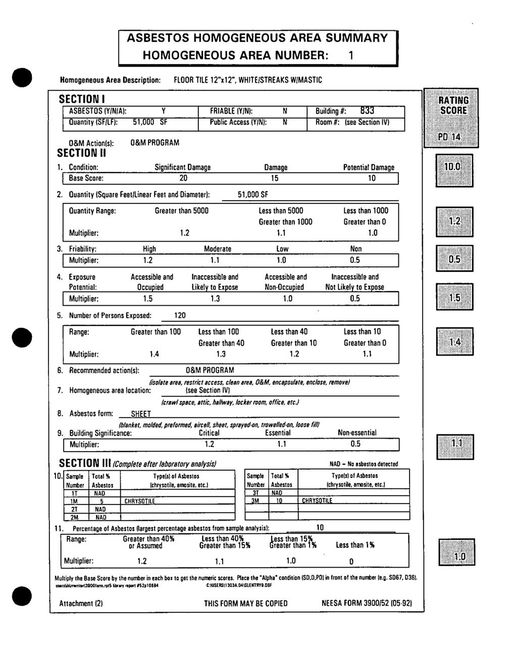
253
254

255
256

257
258
259
260

261
262
263

264
265
266
267
268
269
270
271
272
273
274
275
276
277
278
279
280
281
282
283
284
285
286
287
288
289
290
291
292
293
294
295
296
297
298

299
300
301
302
303
304
305
306
307
308
309
310
311
312
313
314
315
316

317
318

319
320

321
322

323
324
325
326

327
328
329
330
331

332
333
334
335
336
337
338
339
340
341
342
343
344
345
346
347
348
349
350
351
352
353
354
355
356
357
358
359
360
361
362
363
364
365
366
367
368
369
370
371
372
373
374
375
376
377
378
379 3140 Finley Road Downers Grove, IL Fax: July 29, 2004 VIA FED EX PRIORITY Mr. Carlo Luciano DEPARTMENT OF THE NAVY Naval Facilities Engineering Command Engineering Field Activity Midwest ROICC Great Lakes - Building 1-A 201 Decatur Avenue Great Lakes, IL Clayton Project No Re: Asbestos, Lead Paint, Mercury and PCB Survey Building 834 Great Lakes Naval Training Center RFQ No. N A-3034 Call# 0002 Dear Mr. Luciano: Clayton has completed an asbestos, lead paint, mercury and PCB survey of Building 834 in accordance with your RFQ No. N A-3034 Call# This is our report on this work. ASBESTOS-CONTAINING BUILDING MATERIALS SURVEY Visual Inspection Clayton's visual inspection of the building revealed the following materials suspected to contain asbestos: Floor tile/mastics (two patterns) 2' x 2' ceiling tile Baseboard mastic Plaster Floor leveling compound N:\Projohs\ Great Lakes Bldg. 834\LtrRptglnb.doc\PMZ\ck
380 Mr. Carlo Luciano Clayton Project No Department of the Navy July 29, 2004 Environmental Survey Building 834 Page 2 Samples of these materials were collected and submitted to STAT Analysis, an AIHAaccredited laboratory. The samples of flooring were analyzed by Transmission Electron Microscopy (TEM). All remaining samples were only analyzed by Polarized Light Microscopy (PLM). Sampling/Analysis Laboratory analysis showed the following materials to contain no asbestos: 12 Floor tile (two patterns) Yellow mastic 2' x 2' ceiling tile Baseboard mastic Plaster Floor leveling compound Laboratory analysis showed the following materials to contain asbestos: Black mastic The Floor tile located on the fourth floor of the building is consistently the same in each of the rooms and hallway, however the floor tile mastic found in the barracks is yellow in color and does not contain asbestos. The Floor tile mastic in the hallways, adjacent plumbing room and equipment storage room is black in color and contains asbestos. Therefore floor tiles associated with the black floor tile mastic will be treated as asbestos containing materials. See the following table summarizing quantities, general locations and results of specific analysis. SAMPLE NO. MATERIAL LOCATION ACM (%) APPROX. QTY 1-3 2' x 2' Ceiling Tile Throughout Hallway ND N/A 4 12 White w/brown spec floor tile Plumbing room, Storage room, Equipment room 5m-7m Black mastic associated w/ #4 Under carpet in hallway, Plumbing room, Storage room, Equipment room ND* 1-5* Chrysotile N/A 2680sf Total 8 12 White w/brown spec floor tile Barracks ND* N/A 9m-11m Yellow mastic associated w/ #8 Barracks ND N/A Plaster Throughout Hallway and ND N/A barracks * Analyzed by Transmission Electron Microscopy (TEM) ND= Not detectable N/A = Not applicable
381 Mr. Carlo Luciano Clayton Project No Department of the Navy July 29, 2004 Environmental Survey Building 834 Page 3 SAMPLE NO. MATERIAL LOCATION ACM (%) APPROX. QTY Baseboard mastic Throughout Hallway ND N/A Plaster Throughout Hallway ND N/A Gray Floor Leveling Compound Roof ND N/A * Analyzed by Transmission Electron Microscopy (TEM) ND= Not detectable N/A = Not applicable LEAD PAINT, MERCURY AND PCB SURVEY Lead Paint Survey Clayton observed three colors of paint in Building (off white, beige and gray). Sampling/Analysis Paint chip samples were collected and submitted to STAT Analysis for analysis by atomic absorption for lead content. Laboratory analysis showed the samples collected to contain less than 5,000-ppm lead content (the level considered by HUD to be classified as lead-containing). See the following table summarizing results and the attached STAT Laboratory Report. SAMPLE NO. PAINT COLOR LOCATION LEAD CONTENT (ppm) LBP-1 Off White Hallways and Barracks < 100 LBP-2 Beige Hallways and Barracks < 100 LBP-3 Gray Hallways and Barracks < 100 Note: Lead content in paint greater than 5,000 ppm is the level considered by HUD to be classified as lead-containing paint. Mercury Survey A visual survey of Building 834 revealed no HVAC thermostat suspected to contain mercury. The wall thermostats are electronically controlled. There are approximately 78 light fixtures observed in the building and is assumed that all 156 fluorescent light bulbs suspected to contain high levels of mercury sufficient to be classified as hazardous waste. However, if during renovation activities fluorescent light bulbs with green end caps are observed, these are not classified as a hazardous waste
382 Mr. Carlo Luciano Clayton Project No Department of the Navy July 29, 2004 Environmental Survey Building 834 Page 4 according to the U.S. Army Center for Health Promotion and Preventive Medicine. Lamp manufacturers are manufacturing lamps containing low mercury and are depicting them with green end caps. PCB Survey Seventy-eight light fixtures suspected to contain PCB light ballasts were observed. These should be removed prior to the building demolition and disposed as hazardous waste. CONCLUSIONS There were no identified asbestos-containing materials the EPA would require to be removed from the building prior to demolition. The thermal system piping is insulated with fiberglass materials and not subjected to sampling. The 12 floor tile materials identified to contain asbestos would be classified as Category I non-friable, and EPA would allow the flooring to remain in the building during demolition. Materials discovered containing asbestos on the fourth floor of Building 834 would have to be removed prior to any renovation activities that might disturb these materials according the Illinois Department of Public Health Rules and Regulations, Subpart D. No lead-containing paint (as determined by HUD) was identified. No wall-mounted HVAC thermostats are suspected of containing mercury. All thermostats observed throughout the fourth floor of the building are electronically controlled. Seventy-eight fluorescent light ballasts suspected to contain PCBs were identified. A reasonable effort was made to identify the present of ACM. However, this does not imply a guarantee that all possible sources of ACM were identified, as certain building materials may be hidden by walls, flooring, partitions, etc., or may be otherwise inaccessible. During renovation/demolition operations, building materials may be uncovered that may be suspect.
383 Mr. Carlo Luciano Clayton Project No Department of the Navy July 29, 2004 Environmental Survey Building 834 Page 5 We have enjoyed working with you on this project. Please call me at if you have any questions. Report prepared by: Report reviewed by: Paul M. Zilinskas Asbestos Building Inspector License # Lead Inspector License#L-6745 Senior Consultant Chicago Regional Office Steve Rupkey, CIH Senior Consultant/Interim OHS Manager Chicago Regional Office Attachment 1: Facility Layout Map Attachment 2: STAT Laboratory Analysis Reports Attachment 3: Photographs
384 ATTACHMENT 1 FACILITY LAYOUT MAP
385 ATTACHMENT 2 STAT LABORATORY ANALYSIS REPORTS
386 ATTACHMENT 3 PHOTOGRAPHS
387 Table Estimated Removal Costs Sample No. Material Location ACM (%) Approx. Qty Estimated Removal Costs White w/brown spec floor tile 5m-7m Black mastic associated w/ #4 Plumbing room, Storage room, Equipment room Under carpet in hallway, Plumbing room, Storage room, Equipment room ND* To be treated as ACM due to the mastic 1-5* Chrysotile 2680sf Total $8, Total 2680sf Total N/A 1 Note: These are estimated quantities for budgeting purposes only. It is the contractor s responsibility to verify total quantities. Estimated Removal Costs for Mercury A visual survey of Building 834 revealed 78 lighting fixtures containing an approximate total of 156 fluorescent light bulbs suspected to contain mercury and 24 PCB-containing light ballasts. These should be removed prior to renovation and disposed as hazardous waste. Costs for this are estimated to be less than $3,000.


388 Clayton Project Description Baseboard Mastic No Site Name Building Client Great Lakes Naval Base Samples Clayton Project Description Fiberglass Pipe Insulation No Site Name Building Client Great Lakes Naval Base No Samples


389 Mastic Mastic Samples Samples 5m 5m 7m 7m Clayton Project Description 12" White With Brown Speckled Floor Tile No Site Name Building Client Great Lakes Naval Base Sample #4 Leveling Compound Clayton Project Description Grey Leveling Compound No Site Name Building Client Great Lakes Naval Base Samples 22-24


390 Clayton Project Description Electronic Thermostat No Site Name Building Client Great Lakes Naval Base No Sample Clayton Project Description Grey and White Paint No Site Name Building Client Great Lakes Naval Base Samples LBP-03 LBP-01


391 Clayton Project Description Plaster No Site Name Building Client Great Lakes Naval Base Samples Clayton Project Description 2' x 2' Ceiling Tile No Site Name Building Client Great Lakes Naval Base Samples 1-3

392 Clayton Project Description Beige Paint No Site Name Building Client Great Lakes Naval Base Sample LBP-02

393 NAVSTA Great Lakes Building Conditions Report DRAFT Submittal April 2012 BUILDING 834 TSC BEQ USS FRANKLIN B GENERAL DESCRIPTION The four-story building is a Class A barracks that provides sleeping accommodations for Navy enlisted personnel who are trainers or who are in training at NAVSTA Great Lakes. There are 110 barracks rooms. The typical room is setup for double occupancy; an individual desk is under an upper bunk bed for each tenant. The building is located at the very north end of Main Side on the Base. The building is four-stories with a flat roof clad in red face brick with punched windows on the 2 nd and 4 th floors and ribbons of windows on the 1 st and 3 rd floors. The rectangular building shape is broken with a narrow section containing a vestibule on the first floor, and a stairwell, offices, and utility/storage rooms on the other three floors. The longer portion of the building extends to the east with the shorter portion to the west of this narrower section. Near the first floor entry is a breezeway, and on the west side of that is mechanical space. With the exception of the broad walkway at the entrance and the covered walkway separating the mechanical room on the first floor, the building is surrounded by grade that is planted with grass and shrubbery. The longer mass has the first floor half-bermed into the grade. The flat roof on the building has no mechanical equipment; the solar thermal arrays that were present were being removed at the time of the survey. Information about the building is based on field observations, conversations with Base personnel and available building drawings. Building Function Student Barracks Year Built Major Renovations 1983 Square Footage 53,991 Building Occupancy Building Operational Hours Staff: 10 or less, est. Tenant capacity, Max: 218, Current: 198, 100% male. Continuous occupancy Date 12/13/2011 Figure 1: Front, south side Observed Outside Air Temperature and Conditions 38 o F Cloudy - Rain BUILDING ENVELOPE The building envelope assemblies below are in good condition, unless noted otherwise. Building 834, Page 1 of 13
394 NAVSTA Great Lakes Building Conditions Report DRAFT Submittal April 2012 Walls The walls are constructed of loadbearing 8 lightweight CMU with brick veneer. Drawings reveal that the 2 cavity contains rigid insulation but no drainage plane. Practically speaking, there should be 2 or less of extruded polystyrene, or an R values that ranges between 10 and 5. Furthermore, the wall was detailed/drawn to have every 6 th course of brick as a header turned back into the CMU. From the exterior pattern, it s clear that this was not done, and the masons went back to conventional wire ties and cavity wall construction. From an insulating point of view, this is better. Doors Primary entrances are anodized aluminum storefront assemblies with dual glazings. Glazings have a medium bronze tint. Secondary entrances and utility doors are hollow metal construction, flush face and insulated. Windows Windows are anodized aluminum fixed curtain wall or storefront type units in public areas, the lobby, and the ends of the hallways. The lites are dual glazed with a post applied tint film. The punched windows in the sleeping quarters are also aluminum framed units with sliding and fixed sashes. The first and third floors have an arrangement appearing as ribbon windows. However, the panes between the operable units are opaque black, spandrel glass on the outside and the same CMU structure on the inside. It is unknown if or how the spandrel glass is insulated. Ceilings The ceiling in most areas is the hard underside of the structure. In most cases, the floor structure is of 8 precast, hollow-core planks bearing on the CMU walls. In other locations are bulkheads of plaster on small, light gage, metal framing. Other locations have 2 x4 suspended acoustical ceiling tile. Roof The roof structure is also a flat, 8 precast concrete, hollow core slabs. The roof drainage slopes are shown on drawings to be from tapered rigid board insulation. Based on what drawings show and what the roof looks like, the maximum actual insulation thickness varies from 5 down to less than 1. If this is from expanded polystyrene, the insulating value ranges from R=25 to 5, but with a bias toward lower value. The roof weather barrier is in poor condition. The old built-up felts appear to have been flood coated with asphalt emulsion and topped with fibered aluminum paint. This would be a typical repair hoping to extend the life of the roof a couple more years after already nearing the end of useful life. The fibered aluminum paint and asphalt flood coat are deeply cracked or alligatored. Now that the solar panels and framing are off the building, it will make it much easier to do a proper roof replacement. Building 834, Page 2 of 13
395 NAVSTA Great Lakes Building Conditions Report DRAFT Submittal April 2012 Flooring Floors are carpet, with bits of vinyl composition tile and ceramic tile in wet or high traffic areas. UTILITIES The Energy Use Indices (EUI) for this facility are calculated with certain assumptions that may need to be adjusted. Electricity metered at the pad-mounted transformer is for both Building 833 and 834. It is assumed that steam is used in only Building 834 (Building 833 was not audited) for the purposes of heating hot water and domestic hot water for both buildings. Using those assumptions, the total EUI was kbtu/ft 2 during FY2010 and kbtu/ft 2 during FY2011. For the purpose of comparing this level of consumption with an average facility, there is a comparable building type found in ASHRAE Applications Handbook, Chapter 36 (2003 CBECS data). When compared to the EUI for building category Dormitory/fraternity, this facility will rank less than the 25 th percentile for overall energy consumption. When comparing to the Electricity Use Index Value, Buildings 833 and 834 are between the 75 th and the 90 th percentiles for the same building category. The Index Value for FY2010 was 8.92 kwh/ft 2 and the Index Value for FY2011 was 8.21 kwh/ft 2. The higher-than-average index values for this building could be the result of individual room control of HVAC equipment and lack of temperature setback. Electrical A 500 kva pad-mount utility transformer feeds Building 834 along with Buildings 833 and The electrical room for Building 834 is adjacent to the chiller room (west-side mechanical room). There are two (2) main circuit breakers in this space. The first main circuit breaker is rated for 2500 Amps at 120/208V 3-phase. An identical panel/breaker is in this space as well; however, it feeds a separate building across the street (detention building). Since Building 6801 is metered separately, it is assumed that the electric meter installed on the padmount transformer is for Buildings 833 and 834 together. If the meter on Building 6801 is actually a submeter, then its readings need to be subtracted from the readings on the pad-mounted transformer at Building 834. The meter on the transformer is an electronic Square D PowerLogic Ion 8600 with local digital and remote reading capabilities. The local display had values for natural gas and steam. It is assumed that the steam consumption is being monitored via this relatively new meter with an AMI interface (there is no natural gas usage at this facility). Natural Gas/Fuel There is no natural gas associated with Building 834. Building 834, Page 3 of 13
396 NAVSTA Great Lakes Building Conditions Report DRAFT Submittal April 2012 Water & Sewer Water enters the building from the utility tunnel beneath the first floor covered walkway. A 3 inline meter, Niagara serial number , for the building service is located in the tunnel. At the time of the survey, the meter reading was 48,817,338 gallons. There is a booster pump in the basement/tunnel area; it is a base mounted, end suction centrifugal pump. The pump is not operating and appears to have been out of service for quite a while. A bypass pipe and valve is installed and isolation valves for the pump are manually closed. The pump and pipes are thoroughly corroded and could be scrapped. Sewer is available, but is not metered at the building. Alternate Energy Sources & UPS This building is served by the Base central steam distribution system. Steam enters the facility from the utility tunnel beneath the first floor covered walkway. Condensate is pumped from main Mechanical Room 136 back into a return pipe that is also in this tunnel; condensate is metered inside the mechanical room. Although it is not an energy issue for this building, the condition of the steam pipe in the tunnel is an energy and safety issue for the Base. There is a steam leak at a flanged connection that is discharging into the tunnel and is condensing on the walls and equipment there. A particular concern involves all the electrical conduit and wires some of which are exposed due to missing junction box covers which are having steam vapor condense on them. This hazardous condition was pointed out to the NAVFAC Shop employee escort accompanying the auditor at the time of the survey. Process Loads Two (2) Quincy air compressors are located in the mechanical room. The air compressors share a common header and have approximately 100 gallons of storage capacity. The compressed air system is used for the HVAC pneumatic control system throughout the building. The compressor was noted to be operating in Auto and one of the two compressors was cycling repeatedly during the survey. The compressor unloads at 100 psi and loads at about 75 psi. The compressor was noted to cycle quite often (ran for an average of 35 seconds and shut down for an average of 1 minute and 42 seconds for a runtime of approximately 2,238 hours/year). The frequent runtime for the air compressor could be attributed to multiple system air leaks. These leaks could be located and corrected with an air-leak test survey. There are two (2) pop machines and one (1) candy machine in the vending area. These machines are powered on regardless of space occupancy. It is recommended that controls be added to shut this type of equipment off and cycle as needed to maintain product integrity. The lounge area has three (3) computer stations that are powered on continuously regardless of use or space occupancy. This type of equipment operation also contributes to wasted energy. The laundry room on the first floor has 24 stacked Speed Queen washer/dryer combination units. The electric dryers are rated at 5750W and the washers at 1180W each. Almost all of the units had clothes in them at the time of the audit; it is assumed that the laundry equipment is heavily used in this building. Building 834, Page 4 of 13
397 NAVSTA Great Lakes Building Conditions Report DRAFT Submittal April 2012 LIGHTING Interior Lighting Systems Fluorescent Fixtures There are 664 fluorescent fixtures. Two-thirds are 1-lamp 4-ft surface-mount (SM) fixtures with lenses and 2-lamp 2-ft SM fixtures with lenses and 17W lamps. 20% are 2-lamp 2 x2 recessed lensed (RL) troffers, which employ U-tubes with 6-in leg spacing. There are also 4-ft SM fixtures with wrap-around (WA) lenses, 3-lamp 2 x4, 18-cell recessed parabolic (DCP) fixtures and 2-lamp 4-ft pendant-mount (PM) industrial (IND) fixtures. All fixtures are controlled by wall-switches. Most fixtures are in good condition, but several fixtures with wrap-around lenses (WA) had broken or cracked lenses or were missing lenses. Most of the hallway fixtures have dirty lenses. Incandescent Systems: There are lamp 6 recessed cans that have been retrofit with 23W screw-base (SB) CFL lamps. HID Systems: There are no interior HID fixtures. Lamping: All of the fluorescent fixtures are equipped with standard 32W T8 lamps and generic electronic ballasts (GEB). Light Levels Light levels were observed to be in the normal range for most areas, as indicated by a measurement of 36 FC in the vending area. However, the laundry area measured low at 26 FC and the front office area measured high at 63 FC. The foyer airlock area measured 392 FC and is high enough with natural light that turning off the fixtures made no difference in the measurement. Exterior Lighting Systems The exterior lighting system is comprised of 12 1-lamp floodlights with 150W high-pressure sodium (HPS) lamps and magnetic ballasts. Conditions: Overall, fixtures are in good condition. Controls: Exterior lighting systems are controlled by photocells. Building 834, Page 5 of 13
398 NAVSTA Great Lakes Building Conditions Report DRAFT Submittal April 2012 DOMESTIC HOT WATER Domestic hot water is provided by two (2) parallel instantaneous steam-to-hot-water converters located in the Penthouse. The steam pressure provided to these two units is 33 psig as it enters the facility. Water temperatures leaving the converters were both 120 F. There is a single system inline recirculation pump that runs continuously. Return water temperature at the time of the survey was 110 F. The domestic hot water system is in fair condition. At the time of the survey, a leak in the steam supply pipe was being repaired. Corrosion was evident on the uninsulated portion of the pipe. It is anticipated that the repair work will restore the system to good condition. PLUMBING SYSTEMS The lavatories in the barracks rooms are typically fitted with single lever faucets with 2.0 GPM aerators. The toilets are 3.5 GPF tank types that are floor mounted but with a rear discharge. The showers are post mounted Moen showerheads which are either the 2.5 GPM model or the 1.75 GPM model, with a bias toward the later. In the staff or public toilets, there are uncontrolled or 2.2 GPM faucets. The 2.2 GPM aerators are fitted to push button metered faucets with one (1) hot and one (1) cold push button. The floor mount 3.5 GPF toilets have diaphragm valves. One (1) staff private 1.6 GPF toilet is wall mounted with a diaphragm valve, and the associated faucet is a 1.0 GPM aerator with a single lever. There is a single public 1.0 GPF urinal. HVAC & Controls Systems General Description Building 834 is a two-pipe building, where the heating and cooling equipment in the mechanical room share a common distribution system (same circulation pumps used for both systems). Given this characteristic, the heating and cooling systems cannot operate simultaneously. Automatic season changeover valves isolate one system or the other from the pumps and distribution piping. Building 834 is heated by the Base steam distribution system. Steam is converted to hot water in the mechanical room and distributed to air handler heating coils and multiple fan coils throughout the building. Cooling is provided by a water-cooled chiller. The cooling system was off at the time of the survey due to heating season. The chiller, heating equipment and seasonal changeover valves are connected to the Siemens DDC system. Individual room controls consist of original pneumatic controls. It should be noted that the shared chilled water/heating water distribution systems are original to the building. There are sporadic areas of missing pipe insulation. Some pipes and associated components have rust due to condensation during the cooling season. Building 834, Page 6 of 13
399 NAVSTA Great Lakes Building Conditions Report DRAFT Submittal April 2012 Chilled Water System A Carrier 200 ton water cooled chiller (hermetic screw) is located in the main mechanical room (west side of building - external entry). The chiller system was not in operation during the survey due to the heating season. The chiller serves fan coil units and air handling units in both Buildings 833 and 834. The chiller is approximately 17 years old and is approaching the end of its expected useful life. The chiller was being partially rebuilt during the survey. However, based on conversations with base personnel, the chiller has been reliable in operation. Chiller CH-1 is connected to the Siemens DDC system. The DDC system enables the chiller based on outdoor air temperature and provides remote monitoring and programming from a front-end desktop located at the NAVFAC - East shop. Based on conversations with base personnel, the chilled water supply setpoint is constant regardless of cooling demand. There are two (2) building base-mounted, end suction circulation pumps that feed water through the chiller and the two-pipe building distribution system when the facility is in cooling mode. Both pumps provide a constant volume of water regardless of the cooling demand. A single constant volume condensed water pump serves the cooling tower located outside adjacent to the mechanical room. The cooling tower is approximately seven (7) years old and appeared to be in fair condition. Based on conversations with base personnel, the cooling tower has had multiple problems with leaks over the years. It is believed by the NAVFAC Shop representative at the building that the cooling tower was not installed per specification. There are difficulties priming the condenser water pump each year during startup; the net positive suction head appears to be inadequate. Based on conversations with base personnel, the condenser water system is operated as needed to maintain a condensed water setpoint. Heating System Heat exchanger HX-1 is located in the main mechanical room on the west-end of the building. Heat exchanger HX-1 is a shell-and-tube unit that converts the Base distributed steam to hot water. The pressure reducing valve provides 15 psig steam to the heat exchanger control valve. It was noted that the heat exchanger is not insulated. The heat exchanger operates on a reset schedule based on outdoor air temperature. Some pipe thermometers in the system are broken; however, during the survey, the hot water supply temperature was measured at 141 o F. Given the outdoor air conditions at the time of the survey, this appears to be a reasonable expectation for supply temperature. The heating system is connected to the Siemens DDC system. The DDC system operates the two (2) parallel steam control valves to maintain leaving water temperature and provides remote monitoring and programming from a front-end desktop located at the NAVFAC east shop. The hot water is circulated through the building by the same two (2) circulation pumps that handle the chilled water system. Automatic changeover valves connect the pumps to the heat exchanger when the facility is in the heating season. The circulation pumps are constant volume and operate at a constant speed regardless of heating demand. One of the two circulation pumps was operating during the survey. The pumps are in fair condition due to years of service and some corrosion. The heat exchanger is original to the building and has exceeded its expected useful life. Sporadic areas of steam, hot water and condensate piping are original to the building. However, there were no major defects noticed during the survey. Building 834, Page 7 of 13
400 NAVSTA Great Lakes Building Conditions Report DRAFT Submittal April 2012 Air Handling System Air handler B-1 is a make-up air unit located in the fifth floor (Penthouse) mechanical room. This unit provides make-up air for the multiple exhaust fans in the living quarters. B-1 was not operating during the survey due to renovations that were taking place; however, the unit operates continuously during normal operations. B-1 is in fair condition due to years of service. The unit has a three-way control valve for the heating (or cooling) coil; it is served by the building two-pipe system. B-1 has an outdoor air damper and supply damper. The dampers appeared worn and the reliability is questionable. DX Systems (Packaged or Split): N/A Radiant or H&V Units (Gas-Fired/HW/Steam) There are two (2) unit heaters located in the mechanical spaces of Building 834. One heater serves the main mechanical room and the remaining unit is located in the fifth floor mechanical room. Both unit heaters are controlled by single setpoint thermostats. Neither unit was operating during the survey, but both appeared in fair condition due to age. Special Ventilation Systems (Hood, MAUs, etc.): N/A Terminal Equipment (FCU s, Small EF s) All spaces in Building 834 are served by fan coil units. The fan coil units consist of a fan, hot water (or cooling) coil, and three-way control valve. Each fan-coil unit has two controls. A speed dial-type control provides low/med/high fan speed and a separate pneumatic thermostat provides the space temperature setpoint. The thermostat provides no unoccupied setback features. The condition of these controls varied from room to room. However, most of the thermostats function varied in regards to reliability due to age and years of use by occupants. The thermostats control the state of the three-way control valves in the fan coils, which then operate as needed to maintain the space temperature setpoints. Many of the spaces surveyed had relatively high heating setpoints even though the respective space was unoccupied. Sample temperatures were taken during the survey and are listed in the controls section of this report. Multiple exhaust fans serve living quarters, toilet rooms, vestibules, laundry spaces and storage spaces within Building 834. The exhaust fans are manually (by either switches or light switches) controlled with the exception being the vestibule. In this case, the exhaust fan is controlled by a single setpoint thermostat. Manual fan controls leave the potential for fans being left on continuously regardless of demand and/or occupancy. The typical barracks room toilet exhaust fan is interlocked with the light switch. All toilet exhaust fans discharge into duct risers up through the fourth floor with goosenecks above the roof. A sample of the fans during the audit indicated that 30% of them are damaged or inoperable. Building 834, Page 8 of 13
401 NAVSTA Great Lakes Building Conditions Report DRAFT Submittal April 2012 Controls & Operational Characteristics A mentioned previously, there is a mixture of controls in Building 834. The chiller plant and heating plant are connected to the Siemens DDC system with pneumatic actuators on system valves and dampers. The DDC system is remotely monitored and controlled from a front-end desktop located at the NAVFAC - East shop. All fan coil units and exhaust fans are operated locally with standalone manual controls. The manual controls consist of single setpoint thermostats, manual switches and switches interlocked with light switches. All thermostats in Building 834 are pneumatically controlled. The pneumatic system is original to the building. Based on field observations, there are believed to be considerable air leaks within the pneumatic system. Many fan-coil unit controls have reliability issues in one form or another. Opportunities for DDC upgrades and/or air leak test surveying could exist. Approximately half of the fan-coil unit controls were found to be in some degree of disrepair. Given the age and heavy use, these controls have little useful life remaining. Some thermostats setpoints do not respond to manipulation. Some fan speed controls do not respond to manipulation. Some thermostats do not display accurate space temperature (those that have that capability). While not all spaces with these types of controls were surveyed, it is reasonable to assume that the remaining spaces are accurately reflected by the survey sample. Many thermostats and/or speed controls are better off replaced rather than repaired. Site temperature samples were taken during the audit and are included in the table below. A standard infrared heat gun was used for temperature sampling. Site Temperatures Device & Location Observed Temperatures Setpoint Sensor Temperature(s) Measured Display Notes Lounge Room o F 69 o F Barracks Room o F o F 2 Barracks Room o F 78 o F 66 o F Barracks Room o F o F 2 Barracks Room o F o F 2 Barracks Room o F o F Barracks Room o F 1 Barracks Room o F 70 o F 69 o F 2 Barracks Room o F o F Barracks Room o F 65 o F 70 o F Barracks Room o F 70 o F 69 o F Barracks Room o F 78 o F 69 o F 2 Notes: 1. Space unoccupied 2. Inoperable thermostat or system non-responsive to existing controls Building 834, Page 9 of 13
402 OBSERVED DEFICIENCIES AND RECOMMENDATIONS NAVSTA Great Lakes Building Conditions Report DRAFT Submittal April 2012 The recommended replacements of the individual sleeping room temperature fan coil controls is not considered to be costs associated with an Energy Conservation Measure (ECM). However, by installing these necessary devices, the pneumatic control system will have less likelihood of experiencing leaks and the air needed for the existing thermostats will no longer be required. It is assumed that operational savings of approximately $602 annually will be realized from the reduction in air compressor work. By adding occupancy sensors and door switches to these new devices, an ECM can be considered. Observed Recommendations, Deficiencies Repairs & Replacements Cost HVAC Systems 1 Air compressor is running too Conduct an air-leak test survey, check for frequently water in the system $1,000 2 Unreliable thermostats and manual Replace 123 fan coil room controls with fan controls in the sleeping quarters standalone electronic devices. $158,656 3 Leak in steam line in tunnel Repair flange connection LC/NC 4 Approximately 30% of toilet exhaust Repair as necessary fans are damaged or are $6,600 inoperable. Building Envelope 1 The roof is in poor condition Replace the roof covering and insulation with a lightweight zonolite concrete topping system with 4-5 of extruded polystyrene, with a reflective siplast veral coating. (higher value) or near equal for $201,420 - $477,950 equal existing system 160 mil SBS modified bitumen with 4 extruded polystyrene. Lighting 1 Fixtures with wrap-around (WA) lenses have missing or damaged lenses. 2 x2 fixtures use expensive U-tubes. Replace fixtures with WA lenses with new fixtures with WA lenses, NEMA- Premium instant-start electronic ballasts and install 32-w 85 CRI 5000K Super T8 lamps. Retrofit the 2 x2 fixtures with a reflector kit and use 17W T8 lamps and NEMA-Premium instant-start electronic ballasts. Retrofit 3-lamp parabolic fixtures with retrofit kit, such as RELIGHT to convert to a 2-lamp w/ 12-cell louver, and use 32-w Super T8 lamps (85 CRI) & NEMA-Premium low-power, instantstart electronic ballasts (BF=0.78). Retrofit other fixtures with Super T8 lamps & NEMA-Premium low-power, instant-start electronic ballasts (BF=0.78) $60,000 Water Conservation 1 Faucets aerators are missing Install 0.5 GPM aerators, as needed $15 ea Other 1 N/A Building 834, Page 10 of 13
403 JUSTIFICATION FOR RE/RETRO-COMMISSIONING (RCx) NAVSTA Great Lakes Building Conditions Report DRAFT Submittal April 2012 The purpose of retro-commissioning is to verify and, correct when possible the proper operation of existing system(s) being commissioned. The original design, interpreted by current occupant use, is used to establish the criteria for what proper operation looks like. Energy-affecting systems observed during an audit of this scope, and which are likely candidates for RCx, include: HVAC equipment, HVAC controls, lighting controls, domestic hot water, and renewable energy systems. Certain process loads, such as food preparation equipment, may also be observed for recommendations. The lighting controls and the domestic hot water system are not sophisticated enough to warrant a detailed retro-commissioning effort. There was a 20-year-old solar thermal system installed on the roof; however, it has been out of service for a number of years and was being removed from the building at the time of the survey. The supporting steel structure was also being removed. The DDC system comprises a small part of the total building HVAC equipment inventory. Based on the survey, existing pneumatic control devices are in such poor condition that RCx work would discover too many inoperable and un-repairable situations to be a productive effort. It is recommended that the pneumatic and manual switches in the 110 quarters be completely replaced with electronic devices. Based on conversations with base personnel, the chilled water system does not have a reset schedule. There can be some degree of reset implemented with the existing DDC system. Reset of the chilled water supply temperature based on outside air are minor programming changes; they are not a retrocommissioning project. Therefore, a retro-commissioning project is not recommended for Building 834. PREREQUISITES TO RE/RETRO-COMMISSIONING: N/A RENEWABLE ENERGY OPPORTUNITIES Solar collectors were installed more than 20 years ago in order to provide hot water for the building. Collectors covered the flat roof of this building and also the adjacent BEQ, Building 833. At the time of the audit, these collectors and their support frames were being removed. The system had not been operational for a number of years. In reference to solar PV, the roof now has its solar thermal panels removed. It could support PV panels instead, but because of the association and dislike for solar at this facility, no recommendation is made. For geothermal energy, there is a yard on the north that could support a field of 45 bores. Since the installed capacity is a single 200 ton water cooled chiller, there s not a good match here. Like much of the rest of the base, wind energy is not a good match. Building 834, Page 11 of 13
404 POTENTIAL ENERGY & WATER SAVINGS OPPORTUNITIES NAVSTA Great Lakes Building Conditions Report DRAFT Submittal April 2012 The following table provides a list of potential energy and/or water savings opportunities that are identified for detailed cost and savings analyses. Results of the analyses are included in the ECM Matrix spreadsheet and in the ECM report. Potential Energy & Water Savings Opportunities Notes HVAC Systems 1 Implement chilled water reset based on OAT Requires a DDC revision on existing system 2 Install occupancy sensors or equivalent Controls require door sensors, infrared motion controls in barracks to provide the capability of sensors and programmable thermostats. New unoccupied or night setback temperature on controls could utilize existing 24V system. fan-coil units 3 Insulate the building heating hot water heat exchanger Building Envelope 1 Replace roof with adequate insulation Install 6 expanded polystyrene insulation encapsulated in lightweight concrete topping. Install Syplast veral aluminum modified bitumen cap sheet. 2 Insulate CMU cores with core-fill 500. Lighting 1 Fixtures with wrap-around (WA) lenses have missing or damaged lenses. 2 x2 fixtures use expensive U-tubes. 2 HID fixtures can be replaced with lower wattage alternatives 3 Interior lighting systems are controlled by wall switches in numerous locations. Exterior lighting is controlled by cadmium-sulfide (CdS) photocells. Water Conservation 1 Replace water fixtures with new more efficient models Replace fixtures with WA lenses with new fixtures with WA lenses, NEMA-Premium instant-start electronic ballasts and install 32-w 85 CRI 5000K Super T8 lamps. Retrofit the 2 x2 fixtures with a reflector kit and use 17W T8 lamps and NEMA-Premium instant-start electronic ballasts. Retrofit 3-lamp parabolic fixtures with retrofit kit, such as RELIGHT to convert to a 2-lamp w/ 12-cell louver, and use 32-w Super T8 lamps (85 CRI) & NEMA- Premium low-power, instant-start electronic ballasts (BF=0.78). Retrofit other fixtures with Super T8 lamps & NEMA-Premium low-power, instant-start electronic ballasts (BF=0.78) Replace exterior 150-w HPS floodlight with a new floodlight with 150-w ceramic MH lamps and electronic ballasts. Install dual-technology (PIR & ultrasonic) vacancy sensors (with daylight override in offices with windows) in office spaces, restrooms and break rooms. Replace photocells with silicon photocells. Building 834, Page 12 of 13
405 NAVSTA Great Lakes Building Conditions Report DRAFT Submittal April 2012 Potential Energy & Water Savings Opportunities Other 1 Install vending machine controls to base operation on occupancy 2 Investigate options for control retro-fits for computer stations and video games Notes Building 834, Page 13 of 13
406 Domestic Hot Water Equipment Type Location Mfg Model Year Rating Input- Output Gallon Storage Capacity Degree F. Set Point Circ Pumps Yes or No Size Pump Control Condition Poor, Fair, Good HX-7 Penthouse NA NA gal/hou 120F Yes, 1/6 Hp Switch Fair HX-8 Penthouse NA NA gal/hou 120F Yes, 1/6 Hp Switch Fair P-4 Penthouse NA NA gpm NA 1/6 Hp 24/7 Fair P-5 Penthouse NA NA gpm NA 1/6 Hp 24/7 Fair
407 Cooling Systems Unit Location Type Mfg Model CH-1 CT-1 Mech Room Outside Mech Room Hermetic screw liquid chiller Serial Number Nominal Capacity (Cooling/H eating) Refrigerant Electrical Year Carrier 23XL1111NC4G 1596J Ton R /3/ Location Areas Serviced Cross-flow cooling tower Marley NC8302EL1SG NC A1 200 Ton? NA 208/3/ CH-1 P-2 Mech Room Base mounted centrifugal P-3 Mech Room Base mounted centrifugal P-1 Mech Room Base mounted centrifugal Condenser Water Pump B&G w/ US Electric B&G w/ US Electric B&G w/ US Electric NA NA NA NA NA NA 265 gpm / 10 Hp 265 gpm / 10 Hp 446 gpm / 10 Hp NA 200/3/60 NA NA 200/3/60 NA Building Cooling Chilled Water Loop Chilled Water Loop NA 200/3/60 NA Cooling Tower
408 Heating Systems Unit Location Type Mfg Model Serial Number Control Nominal Capacity Year Location Areas Serviced P-2,3 Mech Room Circulation pumps are shared with cooling system (dual temp building) B-1 Mech Room Shell & Tube NA NA NA DDC 4210 steam #/hour, 265 gpm 1983 Building Heating
409 Air Handling Systems Unit Location Type Mfg Model Total CFM Outside CFM Motor HP Heating Method Heating Rating Cooling Method Cooling Rating Control Year Condition Areas Served B-1 Penthouse Horiz. Drawthru, constant volume Trane CCDB06AW0C Hot Water Coil Btu NA NA 24/ Poor Building Make-up Air
410 Ventilation Systems Unit Location Type Mfg Model Service Total CFM Control Status at Time of Survey Blower HP B-1 Rooms 122,124 Inline NA NA Rooms 122, Light switch On 1/ B-2 Room 120 Inline NA NA Laundry 450 Switch On 1/ B-3 Room 237 Inline NA NA Room Switch Off 1/ B-4 Room 337 Inline NA NA Room Switch Off 1/ B-5 Room 437 Inline NA NA Room Switch Off 1/ B-6 Room 132 Inline NA NA Room Light switch 1/ EF-1 to 110 Each living space Ceiling Bathroom Exhaust NA NA Toilet/Shower Exhaust Year 50 Light switch Varied 1/
411 WATER AUDIT WORKSHEET BUILDING (Numbers): 834 Page : 1 Of: 1 DATE : Fixture Faucets, Lav., Kit. Etc. Toilets Urinal Shower 28-Nov Other BUILDING # or name, Wing, Region or Floor Room #s, Men's, Women's, etc. Count: (# OF) Flow: (gpm, spc) Faucet type: SL, DL, IR, M, KB, LT, JANitor, Condition: (G, F, P) and/or Note : (A, B, C) Count : (# OF) Flow: (gpf) Supply Valve Type: (TT, PT, DV, PV, DF) 1 Staff - Private SL G DV WM G 2 Laundry b 3 Typical Barracks SL G/A TT FMR G/A pm C+A 4 1st Men 2 U SL P/D DV FM F/E DV 5 1st Women 3 U SL P/D DV FM G 6 Men M F DV FM G (F) Metered Push button lav faucet w/ 6 sec. run E D Notes Faucets: Flush Supply: Toilet mount: Shower: Flow: One toilet is shut off Uncontrolled and leaking badly, 4 drips/sec, one is shut off. Moen A M shower head Mount (FM, FMR, W) Condition: (G, F, P) and/or Note : (A, B, C) C B 24 stack washer/dryers - speed queen, fairly new, ie energy star A There are 81 typical rooms, so 162 faucets, 81 toilets, 81 showers. SL Single Lever, DL Dual Lever or Knob, IR Infrared Sensing, M Metered, KB Kitchen Break Faucet, LT Laundry Tub, JANitor TT Tank Type, PT Pressure Tank, DV Diaphragm Flush Valve, PV Piston Valve, DF Dual Flush, WL Waterless (Urinal) FM Floor Mount, FMR Floor Mnt. Rear Discharge, W Wall Mount PM Post Mount, SW Shower Wand w/flex hose U-Uncontolled, No Aerator, estimated at 5 gpm Count: (# OF) Flow: (gpf) Supply Valve Type: (DV, PV, WL Waterless) Condition: (G, F, P) and/or Note : (A, B, C) Count: (# OF) Flow: (gpm) Mount: (PM, SW) Condition: (G, F, P) and/or Note : (A, B, C) Other Note : (A, B, C) Clothes Washers, etc.
412 INDUSTRIAL HYGIENE CONSULT RECORD Date: 27 March 2012 Project No: POC: Mr. Ralph Mirabella, Safety Officer, Unaccompanied Housing Subject: HVAC Duct Lining Sampling for Mold Examination, 07 March 2012 End: (1) Direct Microscopic Examination Report (2) Fungal Culture Report Nature of Consult: At the request ofmr. Ralph Mirabella, samples of fiberglass duct lining for mold detennination were collected from room 117 of Building 833 and room 117 of Building 834. One sample was collected from the duct in Building 833 and two samples were collected from the duct in Building 834 by Mr. Tom Straits and Mr. Brian Malone of the Industrial Hygiene Division. Also present during the sampling were Mr. Mirabella of Unaccompanied Housing and LT Eickmeyer and LTJG Antoine of Environmental Health. The samples were submitted to EMLab P&K for direct microscopic examination on 09 March Results were received on 14 March EMLab P&K was contacted on 15 March 2012 and a request was made to culture the samples submitted for viable mold spore determination and speciation. These results were received on 23 March Findings: Results from direct microscopic examination indicated mold spores and mold structures were present in the bulk samples submitted. Fungi identified included Cladosporium, Aspergillus and Penicillium species. The report of results is included in enclosure (1). One sample from Building 833 and one sample from Building 834 were tested to determine whether the mold was viable. Viable spores reported include Cladosporium sphaerospermum. Aspergillus sydowii, Aspergillus versicolor, Penicillium citrinum. and Penicillium decumbens. Results are shown in enclosure (2). Discussion: The laboratory results show that mold growth had occurred in the fiberglass lined ducts in both Buildings 833 and 834. Additional testing confinned that viable mold spores remain in the duct lining in both buildings. This suggests that mold growth will likely become established when temperature and humidity conditions present a favorable environment for growth. All viable mold spores recovered are common environmental microorganisms. The risk of infections by opportunistic pathogens, such as these, is low for healthy individuals. However, exposure can cause serious respiratory infections for individuals who are severely immunosupressed.
413 Summary (Provided by Jerald Cook MD, MS LT, MC, USN, Medical Officer, Occupational and Environmental Medicine) Molds and fungi are microscopic single cell organisms that are pervasive in indoor and outdoor environments. The claims of health effects related to mold can be quite extensive. Studies have shown that when airborne mold counts are higher, there is an increase in allergic rhinitis and allergy symptoms. Other symptoms such as memory loss, headaches, and decreased energy remain suspect, with no clear association to elevated airborne mold counts. There are no good critelia for using a type of mold or concentration ofmold to make informed decisions regarding remediation. There are not any defined safe or unsafe airborne levels. It is practical, however, to attempt to limit exposure to mold to prevent mold related health outcomes. Health outcomes from mold exposure are due to the susceptibility of the individual. Rare systemic infections do occur, but these primarily occur in severely immunocompromised individuals. For individuals who are sensitized to the pathogen, any exposure may cause them to have a hyperactive immune response such as allergic rhinitis or an asthma attack. Recommendations: Remove mold contamination from inside the ducts and clean interior surfaces. Additional remedies needed to prevent recurrence ofmold-related issues may include improving fresh air supply to individual rooms and ensuring that bathroom exhaust fans are sized to remove excess humidity. A building HVAC engineer should be consulted to develop a comprehensive solution for the building. A copy of this consult record was delivered to Mr. McLaughlin's office on 27 March Mr. Tom Straits, MPH, CIH Industrial Hygienist IH Division FHCC
414 EMLabP&K 1936 Olney Avenue, Cherry Hill, NJ (866) Fax (856) Client: Veterans Health Administration Date ofsubrnittal: C/O: Thomas Straits Date of Receipt: Re: ; HVACDuctLining Date of Report: DmECT MICROSCOPIC EXAMINATION REPORT Background Miscellaneous MOLD GROWTH: Molds seen Other General Debris and/or Spores Present* with underlying mycelial and/or Commentstt Impression Description sporulating structurest Lab ill-versiont: , Analysis Date: 03/14/2012: Bulk sample : B-833, Room 117, Bottom Insulation None 4+ Cladosporium species (spores, None Mold growth hyphae, conidiophores) 1+ Aspergillus species (spores, hyphae, conidiophores) Lab ill-version: , Analysis Date: 03/14/2012: Bulk sample : B-834, Room 117, Bottom Insulation None 4+ Cladosporium species (spores, hyphae, conidiophores) None Mold growth 4+ Penicillium species (spores, hyphae, conidiophores) Lab ill-version: , Analysis Date: 03/14/2012: Bulk sample : B-834, Room 117, RT Side Insulation None 4+ Cladosporium species (spores, hyphae; conidiophores) None Mold growth 4+ Penicillium species (spores, hyphae, conidiophores)" Indicative of normal conditions, I.e. seen on surfaces everywhere. Includes baslciiospores (mushroom spores), myxomycetes, plant pathogens such as ascospores, rusts and smuts, and a mix ofsaprophytic genera with no particular spore type predominating. Distribution ofspore types seen m.irrors that usually seen outdoors. t Quantities of molds seen growing are listed in the MOLD GROWTH column and are graded 1+ to 4+, with 4+ denoting the highest numbers. tt Some comments may refer to the following: Most surfaces collect a mix of spores which are normally present in the outdoor enviromnent. At times it is possible to note a skewing of the distribution of spore types, and also to note "marker" genera which may indicate indoor mold growth. Marker genera are those spore types which are present normally in very small numbers, but which multiply indoors when conditions are favorable for growth. t A ''Version'' indicated by _"x" after the Lab ID# with a value greater than 1 indicates a sample with amended data. The revision number is reflected by the value of "x". Enclosure (1)

415 KMLabP&K 1936 Olney Avenue, Cherry Hill, NJ (866) Fax (856) Client: Veterans Health Administration Date of Submittal: C/O: Thomas Straits Date of Receipt: Re: ; HVAC Duct Lining Date of Report: M0IdlFungaIGrowtbRating Dtll e a s Growth Rating Quantities of molds indicating growth are listed in the MOLDIFUNGAL GROWTH section. Judgement is used in determining the amount of growth present in the sample. For example, if only one portion of the sample has evidence of heavy growth, then it will receive a rating of heavy growth even though, strictly speaking, on a percentage basis of the entire sample, the amount of growth is low. SwabffapelDusUWipe sample Bulk Sample <1+ Evidence of very light growth observed on the sample Areas ofvery light growth detected by the presence of (Very as indicated by spores of one type seen with underlying spores of one type seen with underlying mycelial and/ Light mycelial andlor with their sporulating structures found or with their sporulating structures in the bulk sample. Growth) in less than 10% of the microscopic fields examined. 1+ Evidence of light growth observed on the sample as Areas of light growth detected by the presence of (Light indicated by spores of one type seen with underlying spores of one type seen with underlying mycelial and! Growth) mycelial and/or with their sporulating structures found or with their sporulating structures in the bulk sample. in 10 to 25% of the microscopic fields examined. 2+ Evidence of moderate growth observed on the sample Areas ofmoderate growth detected by the presence of (Moderate as indicated by spores of one type seen with underlying spores of one type seen with underlying mycelial and/ Growth) mycelial and/or with their sporulating structures found or with their sporulating structures in the bulk sample. in 26 to 50% of the microscopic fields examined. 3+ Evidence ofheavy growth observed on the sample as Areas of heavy growth detected by the presence of (Heavy indicated by spores of one type seen with underlying spores of one type seen with underlying mycelial and.! Growth) mycelial and/or with their sporulating structures found or with their sporulating structures in the bulk sample. in 51 to 75% ofthe microscopic fields examined. 4+ Evidence ofvery heavy growth observed on the sample Areas of very heavy growth detected by the presence of (Very as indicated by spores of one type seen with underlying spores of one type seen with underlying mycelial and! Heavy mycelial and/or with their sporulating structures found Growth) to be nearly confluent in the majority of the or with their sporulating structures in the bulk sample. microscopic fields examined. Misee11aneous sipores Slides/specimens are examined for the presence ofmold spores and pollen, noting the quantities and distribution of spore types found. A designation of 'normal trapping' is made when a mix of spore types is present with the same general distribution as is usually found outdoors. In other words, the biological component of the sample surlace is like that found everywhere. Types of spores present would include basidiospores (mushroom spores), myxomycetes (slime molds), plant pathogens such as ascospores, rusts and smuts, and a mix of saprophytic genera with no particular spore type predominating. Many of these spore types would not be found growing indoors on building materials since many plant pathogens require living plants for growth, and mushrooms require compost, leaf duff of various types, or associations with roots of certain trees, etc. Due to these factors, when a mix of spores seen include these types as well as pollen, the rational source is the outside air, rather than indoor mold gr.owth. '!he numbers of miscellaneous spores seen are graded and described as shown below as none, very few, few, variety, and WIde vanetv.. None Very Few Few Variety Wide Variety No spores detected Very few spores A few spores detected detected Many spores containing a variety of different genera detected Many spores containing a wide variety of different genera detected EMLab P&K, LLC EMLab ID: , Page 1 of 1
UNIFIED FACILITIES GUIDE SPECIFICATIONS. References are in agreement with UMRL dated January 2017
 USACE / NAVFAC / AFCEC / NASA UFGS-01 20 00.05 20 (January 2012) Change 1-09/15 Change 2-03/17 ----------------------------------- Preparing Activity: NAVFAC Superseding UFGS-01 20 00.05 20 (February 2011)
UNIFIED FACILITIES GUIDE SPECIFICATIONS. References are in agreement with UMRL dated April 2018
 USACE / NAVFAC / AFCEC / NASA UFGS-01 20 00.00 20 (November 2011) Change 1-05/16 ----------------------------------- Preparing Activity: NAVFAC Superseding UFGS-01 20 00.00 20 (August 2011) UNIFIED FACILITIES
UNIFIED FACILITIES GUIDE SPECIFICATIONS. References are in agreement with UMRL dated October 2012
 USACE / NAVFAC / AFCESA / NASA UFGS-01 20 00.00 20 (November 2011) ----------------------------------- Preparing Activity: NAVFAC Superseding UFGS-01 20 00.00 20 (August 2011) UNIFIED FACILITIES GUIDE
UNIFIED FACILITIES GUIDE SPECIFICATIONS *************************************************************************** SECTION
 USACE / NAVFAC / AFCEC / NASA UFGS-01 31 19.05 20 (September 2015) Change 1-02/18 ------------------------------------ Preparing Activity: NAVFAC Superseding UFGS-01 31 19.05 20 (May 2014) UFGS-01 31 19.05
Design / Build REQUEST FOR PROPOSAL. Ravine Slope Stabilization for Building 128H
 Design / Build REQUEST FOR PROPOSAL (Final DB RFP Submittal) January 9, 2015 EProject NO. 1333375 Ravine Slope Stabilization for Building 128H at US Naval Station, Great Lakes, Illinois PREPARED BY: JACOBS
Part 2 General Requirements
 Part 2 General Requirements Construct AWBS Addition to Building 31455 D5213083 Naval Air Weapons Station (NAWS) China Lake, CA SECTION 01 14 00.05 20 WORK RESTRICTIONS FOR DESIGN-BUILD 01/12 PART 1 GENERAL
Improvements to Hangar 2146 Aircraft Cooling System and F35 Sun Shades
 WORK ORDER NO. 1583255 & 1583256 CONSTRUCTION CONTRACT No.: Beaufort Area MACC APPROPRIATION: FSRM BE2005R & BE2007R Improvements to Hangar 2146 Aircraft Cooling System and F35 Sun Shades At the MCAS Beaufort,
Naval Station Mayport Repair FRC Building 1553 Mayport, Florida 100% Construction Documents
 Naval Station Mayport Repair FRC Building 1553 Mayport, Florida 100% Construction Documents August 19, 2010 Construction Contract No. N69450-08-D-1781/004 Repair FRC Building 1553 Naval Station, Mayport,
P-196 MARINE CORPS RESERVE VEHICLE MAINTENANCE FACILITY NWS CHARLESTON, SC SECTION DESIGN AND CONSTRUCTION QUALITY CONTROL 11/07
 PART 1 GENERAL 1.1 REFERENCES SECTION 01 45 00.05 20 DESIGN AND CONSTRUCTION QUALITY CONTROL 11/07 The publications listed below form a part of this specification to the extent referenced. The publications
UNIFIED FACILITIES GUIDE SPECIFICATIONS
 USACE / NAVFAC / AFCEC / NASA UFGS-01 45 00.10 20 (February 2010) Changed 1-08/17 ----------------------------------- Preparing Activity: NAVFAC Superseding UFGS-01 45 02.10 (November 2008) UNIFIED FACILITIES
SECTION QUALITY CONTROL
 SECTION 01 45 00 QUALITY CONTROL PART 1 - GENERAL 1.1 DESCRIPTION This section specifies requirements for Contractor Quality Control (CQC) for Design-Bid-Build (DBB) or Design-Build (DB) construction projects.
SECTION CONTRACTOR QUALITY CONTROL
 SECTION 01451 CONTRACTOR QUALITY CONTROL PART 1 GENERAL 1.1 REFERENCES The publications listed below form a part of this specification to the extent referenced. The publications are referred to within
SECTION CLOSEOUT PROCEDURES
 SECTION 017700 - PART 1 - GENERAL 1.1 SUMMARY A. Section includes requirements for contract closeout, including, but not limited to, the following: 1. Substantial Completion procedures. 2. Final Completion
SECTION GENERAL REQUIREMENTS PART 1 - GENERAL I 1 GENERAL REQUIRMENTS
 SECTION 01 00 00 GENERAL REQUIREMENTS PART 1 - GENERAL 1.1 SECTION INCLUDES A. Summary of Work: 1. General 2. Contract. B. Contract Considerations: 1. Schedule of values. 2. Applications for payment. 3.
Construction Contract Performance & Documentation Requirements Update
 ACTIVITY NAME Construction Contract Performance & Documentation Requirements Update Construction Contract Cost & Schedule Adherence Construction Management System (CMS) efiles Revised Payments for Materials
UNIFIED FACILITIES GUIDE SPECIFICATIONS
 USACE / NAVFAC / AFCEC / NASA UFGS-01 11 00 (August 2015) --------------------------- Preparing Activity: NAVFAC Superseding UFGS-01 11 00 (August 2011) UNIFIED FACILITIES GUIDE SPECIFICATIONS References
SECTION NETWORK ANALYSIS SCHEDULES (NAS) FOR DESIGN-BUILD 8/10
 FOR DESIGN-BUILD 8/10") SECTION 01 32 17.05 20 NETWORK ANALYSIS SCHEDULES (NAS) FOR DESIGN-BUILD 8/10 PART 1 GENERAL 1.1 DESCRIPTION The Contractor is responsible for scheduling all design, procurement and construction. A single
SECTION 01 32 17.05 20 NETWORK ANALYSIS SCHEDULES (NAS) FOR DESIGN-BUILD 8/10 PART 1 GENERAL 1.1 DESCRIPTION The Contractor is responsible for scheduling all design, procurement and construction. A single
RENOVATE ELEVATED WATER TANK At the. JOINT EXPEDITIONARY BASE, LITTLE CREEK ~ FORT STORY Virginia Beach, Virginia DESIGN BY:
 DEPARTMENT OF THE NAVY SPECIFICATION NUMBER: eprojects# 1382226 RENOVATE ELEVATED WATER TANK 1553 At the JOINT EXPEDITIONARY BASE, LITTLE CREEK ~ FORT STORY Virginia Beach, Virginia DESIGN BY: NAVFAC MID-ATLANTIC,
Generators Phase III Generators Phase III AT THE
 Generators Phase III 05170066 CONTRACT N40085-17-B-0066 NAVFAC SPECIFICATION NO. 05-17-0066 Generators Phase III AT THE MARINE CORPS BASE, CAMP LEJEUNE, NORTH CAROLINA AND MARINE CORPS AIR STATION, NEW
Specific requirements for individual units of work are included in the appropriate sections in Divisions 2 through 16.
 SECTION 01 77 00 - PROJECT CLOSE-OUT PART 1 - GENERAL DESCRIPTION OF REQUIREMENTS: Definitions: Project close-out is the term used to describe certain collective project requirements, indicating completion
1. This Section includes administrative and procedural requirements for contract closeout including, but not limited to, the following:
 SECTION 01700 - CONTRACT CLOSEOUT PART 1 - GENERAL 1.01 RELATED DOCUMENTS 1. Drawings and general provisions of the Contract, including General and Supplementary Conditions and other Division 1 Specification
SECTION SUPPLEMENTARY GENERAL CONDITIONS
 SECTION 00800 SUPPLEMENTARY GENERAL CONDITIONS PART 1 - GENERAL 1.1 SCOPE OF WORK In general, the Work consists of application of a fluid applied membrane, installation of new tapered insulation, installation
EXHIBIT A SCOPE OF SERVICES FOR. FINANCIAL PROJECT ID(S). Various Projects DISTRICT 2 VARIOUS COUNTIES
. Various Projects DISTRICT 2 VARIOUS COUNTIES") EXHIBIT A SCOPE OF SERVICES FOR FINANCIAL PROJECT ID(S). Various Projects DISTRICT 2 VARIOUS COUNTIES 1 PURPOSE... 3 2 PROJECT DESCRIPTION... 5 3 PROJECT COMMON AND PROJECT GENERAL TASKS... 6 4 ROADWAY
EXHIBIT A SCOPE OF SERVICES FOR FINANCIAL PROJECT ID(S). Various Projects DISTRICT 2 VARIOUS COUNTIES 1 PURPOSE... 3 2 PROJECT DESCRIPTION... 5 3 PROJECT COMMON AND PROJECT GENERAL TASKS... 6 4 ROADWAY
*************************************************************************** SECTION F20 SELECTIVE BUILDING DEMOLITION 02/18
 NAVFAC PTS-F20 (February 2018) ------------------------------ Preparing Activity: NAVFAC SUPERSEDING PTS-F20 (September 2016) PERFORMANCE TECHNICAL SPECIFICATION SECTION F20 SELECTIVE BUILDING DEMOLITION
UNIFIED FACILITIES GUIDE SPECIFICATIONS
 USACE / NAVFAC / AFCEC / NASA UFGS-01 45 00.00 10 (November 2016) ----------------------------------- Preparing Activity: USACE Superseding UFGS-01 45 00.00 10 (February 2010) UNIFIED FACILITIES GUIDE
Town of Bennington, Vermont Pleasant Street and School Street Sidewalk Installation STP EH08(11)
") , Vermont Pleasant Street and School Street Sidewalk Installation STP EH08(11) Request for Qualifications Construction Inspection and Testing Services Issued: January 3, 2017 Due: January 24, 2017 I. INTRODUCTION
, Vermont Pleasant Street and School Street Sidewalk Installation STP EH08(11) Request for Qualifications Construction Inspection and Testing Services Issued: January 3, 2017 Due: January 24, 2017 I. INTRODUCTION
ATTACHMENT D SCOPE OF SERVICES
 ATTACHMENT D SCOPE OF SERVICES OBJECTIVE Owner s Capital Improvement Program (major capital, minor construction, repair, and rehabilitation projects) includes numerous construction and renovation projects.
Copyright 2010 AIA Georgia Institute of Technology Facilities Closeout Procedures. 2/15
 SECTION 017700 - CLOSEOUT PROCEDURES PART 1 - GENERAL 1.1 SUMMARY A. Section includes administrative and procedural requirements for contract closeout, including, but not limited to, the following: 1.
155 North Beech, Casper, WY * (307) * (307) Fax INDEX
 * (307) Fax INDEX") INSTRUCTION TO BIDDERS 155 North Beech, Casper, WY 82602 * (307) 265-0603 * (307) 266-5414 Fax PART 1: INSTRUCTION TO BIDDERS INDEX BIDDING DOCUMENTS. 2 CONTRACTOR APPLICATION FORM.2 EXAMINATION OF CONTRACT
INSTRUCTION TO BIDDERS 155 North Beech, Casper, WY 82602 * (307) 265-0603 * (307) 266-5414 Fax PART 1: INSTRUCTION TO BIDDERS INDEX BIDDING DOCUMENTS. 2 CONTRACTOR APPLICATION FORM.2 EXAMINATION OF CONTRACT
RE-DESIGN CALA SWALE, MCAS, NEW RIVER
 17-0122, Re-Design CALA Swale, MCAS New River, CONTRACT N40085-17-B-0122 NAVFAC SPECIFICATION NO. 17-0122 RE-DESIGN CALA SWALE, MCAS, NEW RIVER AT THE MARINE CORPS AIR STATION, NEW RIVER, NORTH CAROLINA
END OF SECTION SECTION FINAL CLEANING PART 1 - GENERAL 1.1 REQUIREMENTS INCLUDE
 d. Clean exposed hard-surfaced finishes to a dirt-free condition, free of stains, films, and similar foreign substances. Avoid disturbing natural weathering of exterior surfaces. Plumbing Contractor: Clean
ARKANSAS STATE HIGHWAY AND TRANSPORTATION DEPARTMENT CONSULTANT SELECTION PROCEDURES FOR ENGINEERING AND DESIGN RELATED SERVICES
 ARKANSAS STATE HIGHWAY AND TRANSPORTATION DEPARTMENT CONSULTANT SELECTION PROCEDURES FOR ENGINEERING AND DESIGN RELATED SERVICES Section I Application (These procedures do not apply to Design-Build Contracts.)
DAG Architects, Inc. July South Walton Fire District Fleet Maintenance/Logistics Building & Training Tower
 DOCUMENT 001153 - REQUEST FOR QUALIFICATIONS 1.1 PURPOSE, LAWS, AND REGULATIONS A. The purpose of the Prequalification Procedure described in this Document is to provide Owner with a mechanism to evaluate
Bulk Fuel Transfer Pump Station PROJECT TABLE OF CONTENTS
 PROJECT TABLE OF CONTENTS DIVISION 00 - PROCUREMENT AND CONTRACTING REQUIREMENTS 00 01 15 LIST OF DRAWINGS DIVISION 01 - GENERAL REQUIREMENTS 01 11 00 SUMMARY OF WORK 01 14 00 WORK RESTRICTIONS 01 20 00.00
Capital Projects Group Mechanical Work Commissioning Specification
 Capital Projects Group Mechanical Work Commissioning Specification Specification 20 05 40 Revision 0 Date: August 2018 Mechanical Work Commissioning Specification Specification 20 05 40 Publication Date:
REQUEST FOR PROPOSAL DEMOLITION & REMOVAL OF THE OLD TOWN HALL 2278 US ROUTE 4 EAST
 REQUEST FOR PROPOSAL DEMOLITION & REMOVAL OF THE OLD TOWN HALL 2278 US ROUTE 4 EAST MENDON, VT 05701 TOWN OF MENDON, VERMONT August, 2018 1 1. SUMMARY AND BACKGROUND The Town of Mendon s original Town
*************************************************************************** SECTION F20 SELECTIVE BUILDING DEMOLITION 09/16
 NAVFAC PTS-F20 (September 2016) ------------------------------ Preparing Activity: NAVFAC SUPERSEDING PTS-F20 (September 2015) PERFORMANCE TECHNICAL SPECIFICATION SECTION F20 SELECTIVE BUILDING DEMOLITION
Submission, Review and Approval of Construction Documents Submission and Review of a Completed Application for Permit
 Building Code The Florida State University Building Code Administration Program (BCA) was established in 2001 and is responsible for ensuring that all construction activities on FSU owned facilities are
SECTION CONTRACTOR QUALITY CONTROL
 SECTION 01 40 00 PART 1 - GENERAL 1.1 SUMMARY A. This section covers the establishment and operation of the Contractor s Quality Control (CQC) system as specified by the General Conditions of the Contract.
UNIVERSITY OF KENTUCKY Memorial Hall/College of Law Expansion and Renovation UK Project No
 PART 1 GENERAL 1.1 RELATED DOCUMENTS REQUIREMENTS COMMON TO ALL WORK CATEGORIES 1. Drawings and general provisions of the Contract, including General Special Conditions and other Division 1 Specification
~lamance <tount!' 9'~UUJ ;i)epwdment 124 We6t ElmStltm (j,taluun,.ncjjdli &vwfina 27253!Jefepfwae(336) :Jax(336)
epwdment 124 We6t ElmStltm (j,taluun,.ncjjdli &vwfina 27253!Jefepfwae(336) :Jax(336)") ~lamance
~lamance
The University of Alabama General Requirements for Purchase Orders Involving Public Works
 The University of Alabama General Requirements for Purchase Orders Involving Public Works Revised January, 2011 The following items are to be included in the scope of each Purchase Order individually,
Attachment 1 Architectural Services
 A. Phase 1, Programming and Schematic Design: 1. Ascertain the requirements for each project through a meeting with the COUNTY, and a review of an existing schematic layout of each project, if such layout
Florida Cleanroom Systems
 Florida Cleanroom Systems Design Build Projects / Project Quality Control Plan (PQCP) Quality Control / Quality Assurance Manual May 2010 1 TABLE OF CONTENTS Section 1: Introduction 3 1.1 Defining Plan
REQUEST FOR PROPOSALS FOR CONSTRUCTION MANAGEMENT SERVICES. For the renovation of existing apartment buildings. August 15, 2016
 REQUEST FOR PROPOSALS FOR CONSTRUCTION MANAGEMENT SERVICES For the renovation of existing apartment buildings August 15, 2016 INVITATION Bath Housing Development Corporation is soliciting proposals for
COMMUNITY COLLEGE DISTRICT OF JEFFERSON COUNTY, MISSOURI REQUEST FOR PROPOSAL: WINDOW, DOOR, AND FRAME REPLACEMENT
 COMMUNITY COLLEGE DISTRICT OF JEFFERSON COUNTY, MISSOURI REQUEST FOR PROPOSAL: WINDOW, DOOR, AND FRAME REPLACEMENT RFP # 1710002 Sheree Bell Due Date: November 30, 2017 Procurement Coordinator Not later
Cherokee Nation Entertainment Casino Ramona, Oklahoma. WORK PACKAGE: Existing Casino Demolition and Dismantling 8/7/12
 SCOPE SUMMARY: DIVISION: 0 - LEGAL DOCUMENTS Complete; DIVISION: 1 - GENERAL REQUIREMENTS As Applicable; SECTION: - ATTACHED SKETCH Complete; Geotechnical Engineering Report as prepared by Building and
SECTION PAYMENT PROCEDURES
 SECTION 012900 PART 1 GENERAL 1.1 RELATED DOCUMENTS A. Drawings and general provisions of the Contract including General and Supplementary Conditions and other Division 01 Specifications Sections apply
Main Building Auditorium
 Main Building Auditorium Theatre and Lighting Upgrade Moberly Area Community College 101 College Avenue Moberly, Missouri This document contains all necessary instructions and specifications to perform
SECTION QUALITY REQUIREMENTS
 SECTION 014000 - PART 1 - GENERAL 1.1 SUMMARY A. Defines SRP requirements for Contractor Quality Control and Owner Quality Assurance. As an Electric and Water Utility, SRP has many critical facilities.
ADDENDUM NO. 1. TO SCOPE OF WORK: Section 0220, Form 01004/5
 ADDENDUM NO. 1 TO SCOPE OF WORK: Section 0220, Form 01004/5 PROJECT: Tankless Water Heaters Installation Glenn Edge and Rich Martin Apartments and Main Office Water Heater Replacement New Memorial Community
REPAIR WASTEWATER PUMP STATIONS Q-81, Q-95, W-385. Naval Station Norfolk, Norfolk, Virginia
 WORK ORDER NO. 1396630 REPAIR WASTEWATER PUMP STATIONS Q-81, Q-95, W-385 At the Naval Station Norfolk, Norfolk, Virginia DESIGNED BY: NAVFAC MIDLANT; PWD NORFOLK; FACILITIES ENGINEERING 9742 MARYLAND AVENUE
COMMUNITY ACTION CHIP LEAD PROGRAM Bids due to Community Action ATTN: BERNADETTE JOHNSON 175 Main St. Battle Creek, MI 49014
 COMMUNITY ACTION CHIP LEAD PROGRAM Bids due to Community Action ATTN: BERNADETTE JOHNSON 175 Main St. Battle Creek, MI 49014 Owner: Johnson Property Address: Battle Creek MI 49017 Owner Telephone: 1-269-
INTRODUCTION. A. Overview. A. Scope of Work. B. Additional Requirements
 RFP 2019-01 Reeta s Building Demolition City of Morgantown REQUEST FOR PROPOSALS Demolition Contractors INTRODUCTION A. Overview This Request for Proposals ( RFP ) is being issued by the City of Morgantown
1.4 USE OF EXISTING ELEVATORS FOR CONSTRUCTION PURPOSES (NO ELEVATOR CONTRACTOR IS CONTRACTED FOR THE PROJECT)
") 1.4 USE OF EXISTING ELEVATORS FOR CONSTRUCTION PURPOSES (NO ELEVATOR CONTRACTOR IS CONTRACTED FOR THE PROJECT) The use of an existing elevator during construction shall be strictly prohibited. Any deviation
1.4 USE OF EXISTING ELEVATORS FOR CONSTRUCTION PURPOSES (NO ELEVATOR CONTRACTOR IS CONTRACTED FOR THE PROJECT) The use of an existing elevator during construction shall be strictly prohibited. Any deviation
Request for Proposals for: Construction Management Services For The ADDISON PUBLIC LIBRARY INTERIOR RENOVATION
 Request for Proposals for: Construction Management Services For The ADDISON PUBLIC LIBRARY INTERIOR RENOVATION May 19, 2015 The Addison Public Library invites you to submit a reply to this Request for
Request for Proposal # 1703 Water Damage Repair of Murray Mansion
 Request for Proposal # 1703 Water Damage Repair of Murray Mansion The City of Lindsay/Lindsay Public Works Authority, Oklahoma, is accepting sealed proposals for Water Damage Repair of a historic public
TECHNICAL QUESTIONS FOR ITB-DOT-17/ LV DEMOLITION AND CONSTRUCTION OF DISTRICT SEVEN OFFICE SPACE
 TECHNICAL QUESTIONS FOR ITB-DOT-17/18-7004LV DEMOLITION AND CONSTRUCTION OF DISTRICT SEVEN OFFICE SPACE Question 1: Question 2: Question 3: Question 4: Question 5: Question 6: When area configurations
TRIAD ENGINEERING CONSULTANTS, INC.
 TRIAD ENGINEERING CONSULTANTS, INC. 2638 Willard Dairy Rd Providing High Point, NC Suite 100 Plumbing, Mechanical and 27265 (336) 454-0225 Electrical Engineering Services Since 1984 admin@triadengmep.com
DECLARATION OF COVENANTS, CONDITIONS AND RESTRICTIONS RADIANT LAKE ESTATES SUPPLEMENTAL ARCHITECTURAL GUIDELINES ARTICLE I INTRODUCTION AND POLICY
 DECLARATION OF COVENANTS, CONDITIONS AND RESTRICTIONS RADIANT LAKE ESTATES SUPPLEMENTAL ARCHITECTURAL GUIDELINES ARTICLE I INTRODUCTION AND POLICY SECTION 1.1. Pursuant to the Declaration of Covenants,
PART 2 GENERAL REQUIREMENTS
 NAVFAC HAWAII PROJECT NO. KNMD 091041P3 PHASE 3 REPAIR FOR HQ PACAF B1102H (Design-Build) AT PART 2 GENERAL REQUIREMENTS PREPARED BY: HQ PACAF/PMO 25 E Street Suite B-106 JBPHH, HI 96853 REQUEST FOR PROPOSAL
UNIFIED FACILITIES GUIDE SPECIFICATIONS
 USACE / NAVFAC / AFCEC / NASA UFGS-01 45 00.15 10 (November 2016) Change 1-08/17 ----------------------------------- Preparing Activity: USACE Superseding UFGS-01 45 00.10 10 (February 2010) UNIFIED FACILITIES
SECTION BID PROPOSAL FORM. Telephone NO: ( ) Facsimile NO: ( ) Oklahoma License NO:
 Facsimile NO: ( ) Oklahoma License NO:") ISSUE DATE: MARCH 21, 2012 (REVISION 2-08/31/12) PROJECT: CNB BUILDINGS 2 AND 3 CATOOSA, OKLAHOMA OWNER: BID TO: (Mail & Fax) CHEROKEE NATION BUSINESSES 777 WEST CHEROKEE STREET CATOOSA, OKLAHOMA 74015
ISSUE DATE: MARCH 21, 2012 (REVISION 2-08/31/12) PROJECT: CNB BUILDINGS 2 AND 3 CATOOSA, OKLAHOMA OWNER: BID TO: (Mail & Fax) CHEROKEE NATION BUSINESSES 777 WEST CHEROKEE STREET CATOOSA, OKLAHOMA 74015
SECTION GENERAL REQUIREMENTS
 SECTION 01005 GENERAL REQUIREMENTS PART 1 GENERAL 1.01 WORK COVERED BY CONTRACT DOCUMENTS A. Work of this Contract comprises the chiller and cooling tower replacement at Five Oaks Middle School which includes
PROFESSIONAL SERVICES DESCRIPTION FOR THE POSITION OF: Building Commissioning Services
 PROFESSIONAL SERVICES DESCRIPTION FOR THE POSITION OF: Building Commissioning Services SUBMISSION DEADLINE: October 23, 2009 11:00am FAIR AND OPEN PUBLIC SOLICITATION PROCESS FOR PROFESSIONAL SERVICES
Both envelopes must have the following information in the lower left hand corner:
 SECTION 001116 INVITATION TO BID The City of Morgantown is requesting a bid for masonry restoration for the City Hall Building in Morgantown, WV. The Project is for building envelope rehabilitation including
Facilities Planning and Construction (FP&C)
") Appendix 8.4a Facilities Planning and Construction (FP&C) UAA FP&C Quality Assessment Checklist (A) Project: PM: Project ID: Updated:
Appendix 8.4a Facilities Planning and Construction (FP&C) UAA FP&C Quality Assessment Checklist (A) Project: PM: Project ID: Updated:
DESIGN & CONSTRUCTION PHASE COMMISSIONING PLAN TEMPLATE
 DESIGN & CONSTRUCTION PHASE COMMISSIONING PLAN TEMPLATE Based upon B3 Minnesota Sustainable Building Guidelines VERSION 2.1 Notes to the reader have been added to this document within numerous text boxes
DEMOLITION BID. BID OPENING November 20, 2018, 8:00pm. Village of Germantown 306 Prairie St. Germantown, IL 62245
 DEMOLITION BID BID OPENING November 20, 2018, 8:00pm Village of Germantown 306 Prairie St. Germantown, IL 62245 Important Bids will not be reviewed without the following information fully completed and
PUBLICATION Commercial Refrigeration and Process Cooling and Heating R
 TEXAS DEPARTMENT OF TRANSPORTATION SPECIFICATION NO. * COMMERCIAL HEATING, VENTILATION AND AIR CONDITIONING (HVAC) MAINTENANCE AND REPAIR SERVICES PUBLICATION This specification is a product of the Texas
Subject: Statement of Qualifications for Public Safety Building Design
 March 5, 2010 Subject: Statement of Qualifications for Public Safety Building Design The City of Porterville seeks Statements of Qualification (SOQ) from qualified architectural and engineering firms for
Residential Sewer Backup Prevention Program
 City of Wheaton Residential Sewer Backup Prevention Program Please Note: The City reserves the right to modify the policies, procedures and rules of this program or discontinue the program in its entirety
Modernize Task Unit Space / NSWG-3 Building 3806 Little Creek
 eprojects Number: 1561942 Modernize Task Unit Space / NSWG-3 Building 3806 Little Creek At the JOINT EXPEDITIONARY BASE, LITTLE CREEK ~ FORT STORY Virginia Beach, Virginia PREPARED BY: NAVFAC MID-ATLANTIC,
COMMUNITY COLLEGE DISTRICT OF JEFFERSON COUNTY, MISSOURI REQUEST FOR PROPOSAL: ROOFTOP AIR CONDITIONING REPLACEMENT
 COMMUNITY COLLEGE DISTRICT OF JEFFERSON COUNTY, MISSOURI REQUEST FOR PROPOSAL: ROOFTOP AIR CONDITIONING REPLACEMENT RFP # 1710005 Sheree Bell Due Date: November 30, 2017 Procurement Coordinator Not later
REQUEST FOR PROPOSAL: Construction Management at Risk Services Hamilton International Air Cargo Logistics Facility. RFP Components
 REQUEST FOR PROPOSAL: Construction Management at Risk Services Hamilton International Air Cargo Logistics Facility RFP Components CLIENT: TradePort International Corporation, Operators of John C. Munro
ATTACHMENT A. Bid # 6793
 ATTACHMENT A SCOPE OF WORK TECHNICAL SPECIFICATIONS AND CONTRACT DRAWINGS STORAGE SHED INSTALLATION AT THE SAN JOAQUIN COUNTY HOUSEHOLD HAZARDOUS WASTE FACILITY Bid # 6793 Department of Public Works Solid
600 - Phase C Intermediate Review Checklist for the Architect- Engineer
 600 Phase C Intermediate Review Checklist for the Architect Engineer This checklist is to be used by the ArchitectEngineer during Phase C of the Project and shall be included in the Intermediate Review
REQUEST FOR PROPOSALS
 REQUEST FOR PROPOSALS CONSTRUCTION MANAGEMENT SERVICES OCTOBER 09, 2014 EAST BAY REGIONAL PARK DISTRICT Atlas Road Extension Improvements POINT PINOLE REGIONAL SHORELINE PROPOSALS DUE: 2:00PM, NOVEMBER
NORTHWESTERN UNIVERSITY PROJECT NAME JOB # ISSUED: 03/29/2017
 SECTION 01 3100 - PROJECT MANAGEMENT AND COORDINATION PART 1 - GENERAL 1.1 RELATED DOCUMENTS A. Drawings and general provisions of the Contract, including General and Supplementary Conditions and other
NORTHWESTERN UNIVERSITY PROJECT NAME JOB # ISSUED: 03/29/2017
 SECTION 01 4000 - QUALITY REQUIREMENTS PART 1 - GENERAL 1.1 RELATED DOCUMENTS A. Drawings and general provisions of the Contract, including General and Supplementary Conditions and other Division 01 Specification
State Historic Preservation Office. Bidding, Contracting, and Construction Guidelines for the Historic Restoration Fund
 State Historic Preservation Office Bidding, Contracting, and Construction Guidelines for the Historic Restoration Fund April 2014 Table of Contents Conflict of Interest... 3 Floodplains... 3 Hazardous
SECTION CONSTRUCTION OPERATIONS AND SITE UTILIZATION PLAN
 SECTION 01 14 11 CONSTRUCTION OPERATIONS PART 1 - GENERAL 1.1 SUMMARY A. The Construction Operations Plan provides a coordinated construction environment to ensure an orderly, secure and safe operation
INTEGRA DATA CENTER POLICIES AND PROCEDURES
 INTEGRA DATA CENTER POLICIES AND PROCEDURES Integra Telecom, Inc. has adopted the following Policies and Procedures related to our Data Products and Services and use of our Data Centers. The Policies and
B. Sections and all references contained therein form a part of this Section of the Specifications.
 KARGES-FAULCONBRIDGE, INC. KFI: 14-044.00 SEWARD MONTESSORI SCHOOL ADDITION & REMODELING SECTION 260010 - PART 1 - GENERAL 1.01 SCOPE OF WORK A. Drawings and general provisions of the Contract, including
REQUEST FOR PROPOSAL. Construction Management Services Not at Risk
 REQUEST FOR PROPOSAL Construction Management Services Not at Risk The St. Charles County Ambulance District proposes to retain a qualified firm/team for the Construction Management Services Not at Risk
2018 REQUEST FOR PROPOSAL FOR JANITORIAL SERVICES. Alberta Construction Safety Association (ACSA)
") 2018 REQUEST FOR PROPOSAL FOR JANITORIAL SERVICES Alberta Construction Safety Association (ACSA) CLOSING DATE: February 9 th, 2018 SECTION 1 PURPOSE AND CONTENT 1.1 We are Alberta s partner in construction
2018 REQUEST FOR PROPOSAL FOR JANITORIAL SERVICES Alberta Construction Safety Association (ACSA) CLOSING DATE: February 9 th, 2018 SECTION 1 PURPOSE AND CONTENT 1.1 We are Alberta s partner in construction
SECTION PROJECT CLOSEOUT
 PART 1 - GENERAL 1.01 SCOPE OF WORK A. This Section specifies administrative and procedural requirements for project closeout, including but not limited to: 1. Close-out procedures 2. Final cleaning 3.
Appendix D University of Maine System. Supplementary Requirements to AIA Document B Standard Form of Architect s Services
 Appendix D University of Maine System Supplementary Requirements to AIA Document B201-2007 Standard Form of Architect s Services This document provides the Architect s scope of services only and must be
NEW CONSTRUCTION APPLICATION
 NEW CONSTRUCTION APPLICATION CONSTRUCTION COMMITMENT AND CONTRACTOR GUIDELINES The General Contractor is solely responsible for the compliance of these guidelines by all subcontractors, suppliers, and
REQUEST FOR PROPOSAL FOR CONSTRUCTION MANAGEMENT SERVICES NOT AT RISK FOR THE. St. Charles County Ambulance District
 REQUEST FOR PROPOSAL FOR CONSTRUCTION MANAGEMENT SERVICES NOT AT RISK FOR THE St. Charles County Ambulance District Base 3 & Training Facility Construction 4169 Old Mill Parkway St. Peters, MO 63376 September
REQUEST FOR SEALED BIDS No
 REQUEST FOR SEALED BIDS No. 2018-013 Project: Granger Site Development Phase 2 Issued: December 19, 2018 CONTENTS Section 1. Bid Announcement and General Information Section 2. Bid Specifications and Bid
SECTION LEED(TM) DOCUMENTATION FOR DESIGN-BUILD 02/10
 DOCUMENTATION FOR DESIGN-BUILD 02/10") SECTION 01 33 29.05 20 LEED(TM) DOCUMENTATION FOR DESIGN-BUILD 02/10 PART 1 GENERAL 1.1 REFERENCES The publications listed below form a part of this specification to the extent referenced. The publications
SECTION 01 33 29.05 20 LEED(TM) DOCUMENTATION FOR DESIGN-BUILD 02/10 PART 1 GENERAL 1.1 REFERENCES The publications listed below form a part of this specification to the extent referenced. The publications
Document Supplementary Conditions State of Ohio Standard Requirements for Public Facility Construction
 Document 00 73 00 - Supplementary Conditions State of Ohio Standard Requirements for Public Facility Construction Certifications These Supplementary Conditions amend and supplement the General Conditions
Town of Brandon, Vermont Brandon Union St. Sidewalk STP EH 05 (4) Request for Qualifications Construction Inspection and Testing Services
 Request for Qualifications Construction Inspection and Testing Services") , Vermont Brandon Union St. Sidewalk STP EH 05 (4) Request for Qualifications Construction Inspection and Testing Services Issued: March 13, 20192 Due: April 3, 2019 I. INTRODUCTION The, Vermont, herein
, Vermont Brandon Union St. Sidewalk STP EH 05 (4) Request for Qualifications Construction Inspection and Testing Services Issued: March 13, 20192 Due: April 3, 2019 I. INTRODUCTION The, Vermont, herein
The Art Barn is available to be seen by potential vendors by appointment only by contacting EMSA s CFO whose information is listed below.
 October 10, 2018 OBJECT: REQUEST FOR PROPOSAL VENDORS, The ( EMSA ) located at 1600 Dundee Avenue in Elgin, IL 60120 is soliciting vendors with an expertise in construction services-demolition to perform
REQUEST FOR PROPOSAL COMMISSIONING AGENT SERVICES GARRISON ELEMENTARY SCHOOL RENOVATIONS PHASE I
 Dover School District (Owner) requests written proposals to secure commissioning authority (CxA) services for the renovations project at the Garrison Elementary School in Dover, New Hampshire. The Owner
Document B Standard Form of Agreement Between Owner and Architect, Construction Manager as Adviser Edition
 Document B132 2009 Standard Form of Agreement Between Owner and Architect, Construction Manager as Adviser Edition AGREEMENT made as of the in the year (In words, indicate day, month and year.) BETWEEN
SAN DIEGO STATE UNIVERSITY PACIFIC CORNERSTONE ARCHITECTS TENOCHCA HALL PROJECT NO FAN COIL UNITS, RESTROOM AND FINISH RENOVATION
 SECTION 02 41 14 SELECTIVE BUILDING DEMOLITION PART 1 - GENERAL 1.1 SUMMARY A. Section Includes: 1. Procedures for systematic removal of site improvements or portions of exterior and interior of buildings
Highway / Utility Guide
 Oregon Department of Transportation Highway Division Right of Way Section Highway / Utility Guide Railroad & Utilities Unit Right of Way Section STATEMENT OF PURPOSE It is important to understand that
Dick s Sporting Goods Demolition Package
 REQUEST FOR PROPOSAL FOR COMPETITIVE SEALED PROPOSALS TO PROVIDE: Dick s Sporting Goods Demolition Package at Salt Lake City, UT 2425 E. Camelback Rd. Suite 750 Phoenix AZ 85016 Notice of Extended Payment