ENVIROMESH DESIGN GUIDE SERIES VOLUME 1
|
|
|
- Elmer Hunt
- 6 years ago
- Views:
Transcription


1 a design guide for building Gabion Retaining Walls BS EN :2004 BS 8002:2015 ENVIROMESH DESIGN GUIDE SERIES VOLUME 1 JANUARY 2016 Written by Roger Farmer and Neil Holmes
2 Contents 2 Enviromesh design guide for building gabion retaining walls DESIGN GUIDE SERIES VOLUME 1 This design guide for gabion structures has been prepared based on the Code Eurocode 7, Geotechnical Design, BS EN :2004 and BS 8002:2015 SECTION 1 SECTION 2 SECTION 3 Introduction Calculations & computations Gabion specifications & detailing 1.1 Gabion retaining walls Conditions, copyright and limitations What are gabions? Bi-axial welded mesh gabions Hexagonal woven mesh gabions Gabion filling material: selection Gabion filling material: swatches Soil characteristics DESIGN PARAMETERS TYPICAL SOIL FRICTION VALUES Soil characteristics PLASTICITY INDEX TYPICAL SOIL DENSITIES Design methods Design analysis Active thrust calculations Gabion computations STRUCTURAL WEIGHT CENTRE OF GRAVITY Gabion computations STABILITY CALCULATIONS Gabion computations DESIGN CRITERIA GABION DENSITIES Gabion computations COMPLEX CREST PROFILES Introduction Bi-axial welded mesh galfan coated SINGLE WIRE 333, 444, 555 / DUAL WIRE 3**, 4**, 5** Bi-axial welded mesh PVC / zinc coated SINGLE WIRE P27, P38 / DUAL WIRE P Bi-axial welded mesh galfan coated DUAL WIRE 344-D Hexagonal woven mesh zinc coated GABION Z Hexagonal woven mesh PVC / zinc coated GABION P Hexagonal woven mesh PVC / zinc coated MATTRESS P Gabion and mattress sizes Gabion design notes IMPORTANT FACTORS IN DESIGN / CONSTRUCTION 38-44

3 1. Introduction Gabion retaining walls Gabions have long become an established method of construction for retaining structures worldwide, providing economical and environmentally acceptable solutions. These structures are generally designed as mass gravity walls with either stepped or flush faces depending upon the requirements of the engineer and stability calculations. This design guide has been prepared to assist competent structural / civil engineers and architects in the best practice of designing gabion retaining walls. Alternatively, Enviromesh can provide a desk top design feasibility service using dedicated in-house software. This technical service is to support our clients with a design facility aimed at providing the most economical system to meet the clients needs. For advice or assistance with the design of a gabion wall, please contact Enviromesh direct details for which can be found below and at the end of this guide. 1.2 Conditions, copyright, limitations Conditions relating to this design guide This design guide has been prepared by Cerana Limited trading as Enviromesh. Neil Holmes Roger Farmer Commercial Director Technical Director Telephone: +44 (0) Telephone: +44 (0) neil.holmes@enviromeshgabions.co.uk roger.farmer@enviromeshgabions.co.uk Andrew Fields General enquiries Engineering Assistant Telephone: +44 (0) Telephone: +44 (0) Fax: +44 (0) andy.fields@enviromeshgabions.co.uk enquiries@enviromeshgabions.co.uk Copyright The information, specifications and other supporting documentation included herein are the copyright of Enviromesh. No unauthorised copying or distribution of this document is permitted without the prior written permission of Enviromesh. Limitations Whilst every care has been undertaken in the preparation of this guide which is based on BS EN :2004 and BS 8002:2015, it is the user s responsibility to satisfy themselves that the information is correct.


4 1. Introduction What are gabions? The term gabion refers to a modular containment system that enables rock, stone or other inert materials to be used as a construction material. The modules or cages as they are known, are formed of wire mesh fabric panels, jointed to form square, rectangular or trapezoidal shaped units. These units are part pre-assembled in the factory to form a flat-pack system. These flat-pack units are then supplied to the customer and formed into the final shaped module on site with the necessary lacing wire, helicals and / or rings as required. Each module has to be connected to adjacent modules to form a monolithic structure. The term gabion refers to a modular containment system that enables rock, stone or other inert materials to be used as a construction material. The types of mesh used, must be of a non ravelling type such as welded wire mesh or hexagonal woven wire mesh and provided with corrosion protection to suit the required exposure conditions. The gabions are normally machine-filled in layers with the contractor picking the stone over by hand to reduce excessive voids. The exposed faces can be hand-packed to provide an appearance of a dry stone wall. Although some structures are only machine-filled, this procedure is not normally recommended as it may give a high void content which may result in deformation. For gabion structures to perform correctly the quality of installation is of paramount importance.
5 1. Introduction Bi-axial welded mesh gabions These gabions are manufactured from a square mesh, normally of opening size 75.0mm x 75.0mm where the longitudinal wires are welded to the cross wires at their intersection points. This type of fabric manufacture, produces a dimensionally stable mesh. y x This mesh, is produced in standard sheets which are then cut into the required panel sizes to form the flat pack unit. This is done by clipping the face, rear, side and diaphragm panels (intermediate dividing panels) to the base panel so that they can rotate to be folded flat. The lid may be clipped to the front or back panel or left loose dependant upon the unit size. Units can be manufactured in any multiple of the mesh size, but are normally supplied as standard sizes to the industry. Welded mesh gabions can be readily modified on site by cutting the mesh back to the next transverse mesh wire. Welded mesh gabions are available in a number of wire diameters to suit the application or can be manufactured in a combination of mesh-wire specifications to provide economy in supply. The resultant gabions flexibility is dependant upon the choice of wire diameter. Bi-axial welded mesh Nominal dimensions (x) and (y) Gabions: 75mm and Mattresses: 75mm Welded mesh gabions are available in a number of wire diameters to suit the application or can be manufactured in a combination of mesh-wire specifications to provide economy in supply. GABION FLAT-PACKED For more information, please refer to Section 3, Gabion specifications and detailing (see pages 20-44). GABION FORMED INTO A BASKET ON SITE
6 1. Introduction Hexagonal woven mesh gabions These gabions are manufactured from a mesh that has a hexagonal opening which is formed by twisting pairs of wire together with one and a half turns (sometimes referred to as triple or double twist). This type of mesh production is continuous. To form panels, the mesh is guillotined across the weave and the cut ends of the wire are wrapped around a heavier wire to form a selvedge end. y The unit is factory fabricated from one main panel which forms the front, base, rear and lid of the unit with additional panels connected to the base section of the main panel to form the diaphragm and end panels. Dependant upon the manufacturer, the mesh orientation is normally either with the weave horizontal or vertical on the face panel and the connection of the ends and diaphragm to the base is via a spiral wire or pairs of twisted wires, twisted together around the base mesh. This type of mesh is flexible as it can articulate about the twists. It is normally manufactured from a 2.7mm wire diameter. The coatings are either galvanised only, or galvanised and PVC coated. The dimension between the twists is a nominal 80mm for gabions and 60mm for mattresses. Hexagonal double-twist woven mesh Nominal dimension (y) Gabions: 80mm and Mattresses: 60mm This type of mesh is flexible as it can articulate about the twists. It is normally manufactured from a 2.7mm wire diameter. The coatings are either galvanised only, or galvanised and PVC coated. GABION FLAT-PACKED For more information, please refer to Section 3, Gabion specifications and detailing (see pages 20-44). GABION FORMED INTO A BASKET ON SITE


7 1. Introduction Gabion filling materials: selection The design of gabion retaining walls is based on the mass of the contained stone or rock being able to resist the disturbing forces due to soil and external loadings. The design does not consider that the gabion mesh contributes to the stability of the structure. The design code applicable to gabions is BS EN :2004 and BS 8002:2015. In the design of the retaining structure, the principles are the same for both woven and welded mesh gabions. Where walls are subject to possible settlement, woven mesh gabions have more flexibility and therefore may be best suited in these situations. Where a high quality of appearance is needed, welded gabions are superior providing that the correct selection of mesh wire combinations are chosen. selecting the correct filling materials The selection of rock or stone fill is very important, as the performance of a gabion structure is dependant upon its mass. Although the mass is the criteria for design, other factors to be considered are:- The selection of rock or stone fill is very important because the performance of gabion structures is dependant upon their mass. Ideally, all gabions should be fair faced (hand-packed on the exposed faces). Grading of fill Gabion fill is normally a graded fill of between 100 to 200mm in diameter with a nominal 6% of the stone being smaller or larger. The grading can be tightened from 80mm to 150mm providing the control of the grading is good. Stones smaller than the mesh will not be contained by it. The grading is important to ensure that voids within the gabions are minimised, otherwise settlements can occur. Angularity of fill The more angular the fill, the better interlock and the less deformation of the face occurs. Rounded stone has little interlock and results in greater deformation of the face. To overcome the deformation, a heavier mesh wire should be used. Welded mesh gabions are manufactured from 3, 4, or 5mm wire diameters for Galfan coated gabions and 2.7mm or 3.8mm wire core diameters for PVC coated gabions. Therefore for a rounded stone fill, Welded wire mesh gabions should be specified in a 4 or 5mm wire diameter for Galfan coated or 3.8mm for PVC coated units. Crushed concrete or gritstone, although angular, tend to become rounded. They do have greater interlock than rounded stones and therefore 4mm wire diameter in Galfan coated or 3.8mm wire diameter for PVC welded wire mesh should be specified. Quarried stone which is normally angular, is the preferable fill as the interlock is very good. Blocky stone or flat stone when machined filled can result in large voids being present which can result in settlements. Care should be taken when machine filling to minimise large voids. Ideally, all gabions should be fair faced (hand packed on the exposed faces). Where the cost of quarried rock fill is high, the gabions can be filled with two types of fill: a quarried rock or block stone for the exposed face with a cheaper stone fill behind. To assist in placing of differing fills, an additional cell can be incorporated normally set back 300mm from the face during gabion manufacture to assist in the construction.

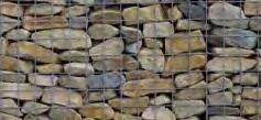
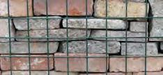

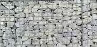
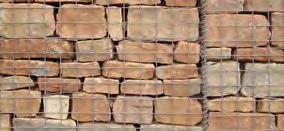
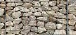


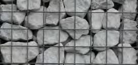
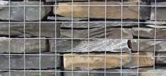
8 1. Introduction Gabion filling materials: swatches COTSWOLD STONE COBBLES CARBONIFEROUS LIMESTONE GRANITE GRITSTONE KENT RAGSTONE HARD SANDSTONE PORTLAND STONE RECYCLED BRICK AND CONCRETE CUT LIMESTONE CORNISH GRANITE SLATE
9 1. Introduction Soil characteristics DESIGN PARAMETERS TYPICAL SOIL FRICTION VALUES Design parameters Before undertaking a gabion wall design, the types of soil being retained and the foundation soil type should be identified by a soil investigation survey to ascertain the correct parameters to use in design. TYPICAL SOIL FRICTION VALUES Soil classification Phi value (degrees) Gabion walls are designed with the drained soil parameters for the retained soils, but the undrained parameters can be considered for the computations for sliding (limitations on the cohesion values that can be taken for design will apply). The design parameters for stability calculations are as follows: LOOSE COMPACT DENSE Sand and Gravel Medium Sand Fine Sand Fine Sand Silty, Sandy Silty Granular materials Silty and Clayey materials Soil friction angle and density Plasticity index and density (correlations exist for assessing the drained soil friction angle with respect to the plasticity index). Chalk (remoulded) 30 to 34 (intact) 32 to 37 Glacial till 33 to 36 Oxford Clay (peak strength) 28 (residual strength) 13 Weald Clay (peak strength) 22 (residual strength) 9 to 15 Gault Clay (peak strength) 26 (residual strength) 22 London Clay (unweathered) 20 to 29 Weathered Clay (peak strength) 17 to 23 London Clay (unweathered) (residual strength) 9 to 17 London Clay (weathered) (residual strength) 10.5 to 22 Note: The above soil information is a guide only and does not negate the need for a proper soil investigation survey to be carried out.
10 1. Introduction Soil characteristics PLASTICITY INDIEX TYPICAL SOIL DENSITIES CORRELATION OF PLASTICITY INDEX AND CBR TYPICAL DENSITIES OF SOILS Soil type Plasticity index % CBR % Soil type Moist weight Heavy Clay >50 <2 40 to 49 2 LOOSE (KN/m 3 ) DENSE (KN/m 3 ) 30 to 39 2 Silty Clay 20 to 29 3 Sandy Clay 10 to19 4 Silt <10 1 Sand (poorly graded) Non Plastic 20 Sand (well graded) Non Plastic 40 Gravel (poorly graded) Non Plastic 40 Sandy Gravel (well graded) Non Plastic 60 Gravels Sand (well graded) Sand (course or medium) Sand (fine or silty) Clay (soft) 17 Clay (firm) 18 Clay (stiff) 19 Clay (very stiff / hard) 20 Glacial Clay (stiff / hard) 21 CORRELATION OF PLASTICITY INDEX AND SOIL FRICTION ANGLE Plasticity index % Phi value (degrees) Interpret linearly for intermediate values. Note: The above soil information is a guide only and does not negate the need for a proper soil investigation survey to be carried out.
11 1. Introduction Design methods Design methods of analysis for determining the stability of gabion walls are based on BS EN :2004 and BS 8002:2015. There are two conditions of design that have to be satisfied: Condition 1: STR Limit State Condition 2: GEO Limit State Class 6N Backfill to be suitably rolled and compacted behind gabion walls in layers not exceeding 300mm and placed in coordination with gabion stone fill. Top soil 21 Dependant on the condition, factors are applied as follows: ACTIONS (A) MATERIALS (M) RESISTANCES (R) Design combination Permanent Variable tan phi unfavourable favourable unfavourable weight density Bearing Sliding Gabion Fill mm quaried stone (Class 6G) 6 NW15 Geotextile The factors are applied as follows: 300mm Combination 1: (A1 + M1 + R1) 45+phi/2 Combination 2: (A2 + M2 + R1) Both conditions must be satisfied. 300mm 300mm Min. 300mm 6F5 Sub Base Gabion walls form typically a trapezoidal format, formed of a number of courses with the width of each course reducing as the wall height increases. The walls may be flush-faced or stepped as required by design or visual requirements, and are normally inclined at 6 degrees for 2.7 or 3mm wire diameters and 6 or 10 degrees to the vertical for 3.8mm, 4.0mm or 5.0mm diameters. Gabion courses should not overhang greater than 150mm to the course below except where the structure is a stepped revetment. Gabion walls form typically a trapezoidal format, formed of a number of courses with the width of each course reducing as the wall height increases.
12 1. Introduction Design analysis Stability checks Once the initial section has been determined, stability checks can be carried out. The provision for any superimposed surcharge loadings to the retained soil both in the construction stage and the permanent condition must be accounted for. Normally, a typical construction loading is taken as 10kN/m 2 for retained soils with nominal inclinations. If unusual construction plant is to be used in the vicinity of the wall, then the superimposed loading should be increased accordingly. Category of traffic areas Footways, cycle tracks and footpaths 5 Normal vehicle traffic 1m from rear face of structure 10 Special vehicle traffic (vehicles conforming to STGO A [LM3 SV models] or SO B regulations) 0.5m but <1m from rear face of structure 20 1m from rear face of structure m but <1m from rear face of structure 30 Normal rail traffic (on areas occupied by the tracks) 50 Light rail traffic Imposed load, q k kpa A Special Types General Order (see BS EN ). B Special Order (see BS EN ). C To be determined for the specific project. Where the retaining wall height is large or is built within a slope or in clayey material, it may be necessary to carry out an overall slope stability check for a circular failure plane which passes beneath the structure in the soil strata. C Coulomb s analysis This is a mathematical analysis based on considering a coefficient of active thrust for the soil. The method considers the soil parameters and the friction developed at the back of the wall and the angle of the retained slope. The analysis is limited to retained soil profiles which have a single grade, but more complex slopes can be considered by rationalising the complex surface to a single grade and applying a continuous surcharge to approximate the profile. It can only consider a continuous single surcharge, but methods are available to deal with line or point loadings on the retained soil. Data required for design Geometry Vertical wall height h m Slope angle of the retained soil ε degrees Soil parameters Soil friction angle φ degrees Density γ kn/m 3 Loadings Surcharge po kn/m 2 Allowable bearing pressure δ kn/m 2

13 2. Calculations and computations Active thrust calculations Wall friction The wall friction is taken into account in the stability computations as equal to phi for the backfill material. Where no geotextile is required or the rear face is stepped, the value of wall friction is taken as equal to phi of the backfill soil. Where the rear face is flush the wall friction = 0.75 phi of backfill soil. In both cases if the cut angle is greater than 45+phi/2 then use the soil friction angle of the retained soil and not the backfill in the above. For the base frictional value is taken 0.66 x unfactored phi of the founding soil. The section can now be drawn and the forces that act on the wall are shown: Po = surcharge α = wall inclination = 6 degrees ε = slope of retained fill Pa = active thrust δ = wall friction H = effective he dh = height at which active cts Coulomb failure plane = 45 + φ/2 bw = base width Wg = weight of gabions β = effective plane at rear of wall Forces acting on the wall By considering the vector diagram of the forces on the wall based on Coulomb s failure plane, the Active Thrust can be determined from the Coefficient of Active Thrust (Ka). ka= sin 2 βsin (β-φ) 1+ sin 2 (β+φ) sin (φ+δ) sin (φ-ε) sin (β-δ) sin (β+ε) 2

14 2. Calculations and computations Active thrust calculations Active thrust due to soil and surcharges are as follows: Pa soil = 0.5 ka γ H Hi Pa surcharge soil = po ka Hi where Pa soil = active thrust due to soil Pa surcharge = active thrust due to imposed loadings H = vertical effective wall height at rear of wall Hi = slope length of rear face of wall po = surcharge loading above the wall Total active thrust Pa Pa = Pa soil + Pa surcharge The active thrust due to the soil acts at one third the effective height of the wall and for the surcharge it acts at half the wall height. The resultant point of application of total active thrust above the toe of the wall can be calculated from: dh soil = H / 3 [ (H + 3hs) / (H + 2hs) ] dh = dh soil - bw sin α where bw = base width of gabion structure Resolve the active thrust Pa into its horizontal and vertical components, Ph and Pv respectively: Ph = Pa cos ( 90 - β + δ ) Pv = Pa sin ( 90 - β + δ ) δ = wall friction (see page 12) hs = the equivalent height of soil equal to the surcharge loading = po / γs

15 2. Calculations and computations Gabion computations STRUCTURAL WEIGHT CENTRE OF GRAVITY Weight of gabion structure Wg = n 1 uw ud γ d where n = number of courses uw = width of each course ud = depth of each unit γd Wg = density of gabion fill weight = weight of gabion structure Determining the centre of gravity of the gabion structure To determine the centre of gravity of the gabion structure, area moments are taken about the toe of the wall. Sum the area moments of each gabion course about the toe of the wall. For walls with no inclination, determine area moments on the x axis only. For inclined walls determine the area moments on both the x and y axis then correct for the wall inclination. α = wall inclination = 6 or 10 degrees n st ( uw ud ) 1 xg = yg = ( uw ud ) n 1 n 1 n 1 hc ( uw ud ) ( uw ud ) Wg where st = horizontal offset of centre of gravity of each course about the toe of the wall considering wall inclination = 0 degrees Xg = horizontal distance of the centre of gravity of the structure about the toe of the wall considering the wall inclination = 0 degrees hc = vertical height to the centre of gravity of each course from the toe of the wall considering wall inclination = 0 degrees Yg = vertical distance of the centre of gravity of the structure about the toe of the wall considering wall inclination = 0 degrees Correcting for the wall inclination α Xg = xg cos α + yg sin α where Xg = vertical height to the centre of gravity of the structure corrected for the inclination of the wall α = inclination of the wall

16 2. Calculations and computations Gabion computations STABILITY CALCULATIONS Forces due to the wall α = wall inclination = 6 or 10 degrees Xg δ Pa Wg dh N R δ bv β Overturning stability Overturning stability is the ratio of the disturbing moment (overturning moment) due to the horizontal component of the active thrust Ph and the restoring moments (moments of resistance) due to the mass of the wall, Wg and the vertical component of active thrust, Pv. Ph and Pv are computed for the soil and each surcharge unless the combined value of active thrust Pa was used:- as computed in Coulomb s analysis. Mo ( moment of overturning ) Mr ( moment of resistance ) Fo ( Factor of Safety Overturning ) = Ph dh = Pv bv + Wg Xg = Mr / Mo where Fo = > 1.0 bv = horizontal distance from toe to point of application of active thrust Pa = bw cos α - dh soil / tan β bw = base width of gabion course under consideration

17 2. Calculations and computations Gabion computations STABILITY CALCULATIONS Sliding stability Sliding Stability is the ratio of the forces resisting sliding (due to the mass of the gabions Wg and the vertical component of active thrust Pv) and the disturbing forces (due to the horizontal component of active thrust moment Ph) on the plane of sliding. N ( normal force on plane of sliding ) = Wg + Σ Pv T ( tangential force on plane of sliding ) = Σ Ph Fs ( Factor of Safety Sliding ) = ( N cos α + T sin α ) tan φ des (founding soil) 0.66 ( T cos α - N sin α ) The value of friction to be taken between courses is based on 35 degrees from test results carried out for BBA certification. where Fs = > 1.0 Bearing capacity The loading on the founding soil must not exceed its allowable bearing capacity. The resultant load is normally eccentric to the centre of the base. Good design practice is to equalise the toe and heel pressures as much as possible either by stepping the gabions or by the inclination of the wall, but do not exceed 6 degrees for lighter 2.7mm or 3mm wire diameters or 10 degrees for heavier wire diameters. e ( eccentricity of result on the base ) = B / 2 ( Mr Mo ) / N where e <= B / 6 (resultant must lie within the middle third of the base) If the wall is founded on concrete then: δ ( bearing pressure on base ) = N / B ( 1+ 6e / B ) at the toe δ ( bearing pressure on base ) = N / B ( 1-6e / B ) at the heel If the wall is founded on a granular material then: δ = N / B ( 1-2e ) where δ <= allowable bearing capacity of the soil

18 2. Calculations and computations Gabion computations DESIGN CRITERIA GABION DENSITIES Design criteria Gabion courses must not overhang the unit below by more than 150mm. A design check must be carried out for each course. The frictional value of gabion to gabion interface is taken as 35 degrees. If the bearing pressures exceed 150kN/m 2 at any course, the gabion unit wire diameter should be increased for the face of the unit and the unit height reduced. If the cut slope is 45 degrees or less, then the wall is designed on the factored retained backfill material. If the cut slope is 45 to 45 + phi backfill / 2 degrees, then the value of the wall friction is based on the factored values of the backfill. If the cut slope is greater than 45 + phi backfill / 2 degrees, the wall friction is based on the factored values of the existing soils. Gabion densities Below are given the typical design densities for various types of gabion fill material: Gabion fill material Flint rejects and whole stone 14.5 Crushed concrete 15 Sandstone 15.5 Limestone 16 Granite 17 Basalt 18 Aggregate fill 16* * geotextile lined units kn per cubic metre Eccentricity (e) must fall within the mid third of the base width of the gabion. The bearing pressures computed must be less than the allowable for the underlying soil. Step the face of the wall to reduce bearing pressures or use a wider founding gabion below to spread the bearing over a greater width (extension of the founding gabion should not exceed the height of the unit).

19 2. Calculations and computations Gabion computations COMPLEX CREST PROFILES Where the retained surface profile is complex, Coulomb s Analysis cannot be used unless it is rationalised to a single slope. The following method is an approximation of dealing with the complex condition. po2 = surcharge po1 = surcharge ε2 = slope of retained fill h po ε equiv =slope of retained fill α = wall inclination = 6 or 10 degrees ε1 = slope of retained fill Coulomb failure plane = 45 + φ/2 Complex crest details In the above diagram, the wall is subject to two surcharge loadings: po1 and po2, together with two slopes. To evaluate this condition, the Coulomb failure plane is drawn until it intersects the free surface. A line is then drawn from the intersection to the rear of the wall at the crest. The angle this makes with the horizontal is then the value of the slope used in the analysis (ε equiv). A line is then drawn parallel to the apex of the triangle above it, the perpendicular height is measured (hs), this height is equivalent to a surcharge of soil on the assumed slope. This surcharge is then calculated: po assumed po design = h po soil = po1 + po assumed or = po2 + po assumed (whichever is the greater)
................. pages 21-22 Gabion series 3**, 4** and 5**.")
20 3. Gabion specifications and detailing Introduction Overview It is important to ensure that the correct specification is used for the gabions / mattresses. The following sheets give the specifications for: BI-AXIAL WELDED MESH Gabion series 333, 444 and (Galfan coated: single wire diameter units) pages Gabion series 3**, 4** and 5**...(Galfan coated: dual wire diameter units) pages Gabion series P27, P (PVC / Zinc coated: single wire diameter units) pages Gabion series P (PVC / Zinc coated: dual wire diameter units) pages Gabion series 344-D (Galfan coated: dual wire diameter units) pages HEXAGONAL WOVEN MESH Gabion series Z27...(Zinc coated) pages Gabion series P27...(PVC / Zinc coated) pages Mattress series P2...(PVC / Zinc coated) pages Aesthetics For schemes where visual quality is not important, either woven or welded mesh gabions are acceptable. For prestige schemes where the visual quality is important, the preferred specification is the Gabion 344-D27 system. Environmental considerations Where the gabions are subject to salt spray, saline water, acidic soils (out of range PH7 to 10) or brackish water, then PVC / Zinc-coated gabions should be specified.
21 3. Gabion specifications and detailing Bi-axial welded mesh gabions galfan coated SINGLE WIRE DIAMETER : GABION 333, 444, 555 The materials, manufacture and supply of this product shall comply with the requirements of BS EN The supplier must confirm adherence to the specifications for materials and manufacturing requirements. MATERIALS The wire used in the manufacture of the gabions and installation accessories shall comply with the following: y x Mesh Fabric The mesh fabric shall be formed by electrically welding at each and every intersection, hard drawn steel line and cross wires into a dimensionally stable bi-axial square metric mesh of size 75mm x 75mm. Weld Strength The weld strength shall be 75% of the minimum ultimate tensile strength of the wire. SPECIFIED MESH BI-AXIAL WELDED Nominal dimensions (x) and (y) : Gabions, 75mm Mattresses, 75mm Wire Diameter The nominal wire diameter for the mesh fabric shall be (select wire diameter 3.0mm, 4.0mm, 5.0mm), all within the tolerances specified in BS EN :2012 and shall have a tensile strength that falls within the range of 540 to 770 N/mm 2. Lacing Wire The lacing wire used for site assembly shall be of a nominal 2.2mm wire diameter in accordance with BS EN :2012 and shall have a tensile strength that falls within a range of 350 to 550 N/mm 2. Helical Binders (where specified, not supplied as standard) Full height helical binders for the vertical joints for gabion installation and assembly shall be of a nominal 3.0mm wire diameter in accordance with BS EN :2012 and shall have a minimum tensile strength of 350 N/mm 2. GABION SIZES It should be noted that it is industry standard for gabions to be quoted as overall nominal sizes. Designation of sizes: length width height. CERTIFICATION 1. All gabion products are manufactured in accordance with the requirements of BS EN :2013 where the gabions are considered to have a life expectancy of up to 50 years in a low aggresive C2 environment (ref. EN ISO 9223:2012 Table 1). 2. Evidence of relevant certificates of conformity with respect to wire strength, weld strength and coating weights used in the manufacture of the mesh fabric and wire products are to be issued upon request.
22 3. Gabion specifications and detailing Bi-axial welded mesh gabions galfan coated SINGLE WIRE DIAMETER : GABION 333, 444, 555 MATERIALS continued Preformed Corner Bracing Ties (where specified, not supplied as standard) Preformed corner bracing ties are to be formed from a nominal 3.0mm wire diameter in accordance with BS EN :2012 and shall have a minimum tensile strength of 350 N/mm 2. y x Corrosion Resistance All wire used in the mesh fabric or accessories shall be Galfan coated (95% Zinc / 5% Al) in accordance with BS EN : 2009 (Class A). MANUFACTURE / SUPPLY SPECIFIED MESH BI-AXIAL WELDED Nominal dimensions (x) and (y) : Gabions, 75mm Mattresses, 75mm Unit Formation The gabion is to be formed from mesh panels such that the front, rear, ends and diaphragm panels are connected to the base panel with either Stainless Steel CL35 clips or Galfan coated CL50 C rings at a maximum spacing of 225mm for all joints. This process must be undertaken in a factory-controlled environment. The lid may be supplied loose or fixed in the same manner to the rear or face panel. Diaphragm (partitioning panels) spacings should not exceed 1.050m on units orientated as stretchers and 1.65m orientated as headers. Should units be required to be prefilled and lifted as opposed to filling in situ, additional clips, rings and mesh panels may be required. In such circumstances the manufacturer must be consulted prior to supply to ensure product is suitable for application. Supply Gabions are to be manufactured and/or supplied by: Enviromesh, Garner Street Business Park, Etruria Stoke-on-Trent, Staffordshire, ST4 7BH. Telephone +44 (0) Fax +44 (0) enquiries@enviromeshgabions.co.uk Online GABION SIZES It should be noted that it is industry standard for gabions to be quoted as overall nominal sizes. Designation of sizes: length width height. CERTIFICATION 1. All gabion products are manufactured in accordance with the requirements of BS EN :2013 where the gabions are considered to have a life expectancy of up to 50 years in a low aggresive C2 environment (ref. EN ISO 9223:2012 Table 1). 2. Evidence of relevant certificates of conformity with respect to wire strength, weld strength and coating weights used in the manufacture of the mesh fabric and wire products are to be issued upon request.
23 3. Gabion specifications and detailing Bi-axial welded mesh gabions galfan coated DUAL WIRE DIAMETER : GABION 3**, 4**, 5** The materials, manufacture and supply of this product shall comply with the requirements of BS EN The supplier must confirm adherence to the specifications for materials and manufacturing requirements. MATERIALS The wire used in the manufacture of the gabions and installation accessories shall comply with the following: y x Mesh Fabric The mesh fabric shall be formed by electrically welding at each and every intersection, hard drawn steel line and cross wires into a dimensionally stable bi-axial square metric mesh of size 75mm x 75mm. Weld Strength The weld strength shall be 75% of the minimum ultimate tensile strength of the wire. SPECIFIED MESH BI-AXIAL WELDED Nominal dimensions (x) and (y) : Gabions, 75mm Mattresses, 75mm Wire Diameter The nominal wire diameter for the mesh fabric shall be (select wire diameter 3.0mm OR 4.0mm for the base, lid, ends and diaphragm panels) and (select wire diameter 4.0mm OR 5.0mm for the front panel), all within the tolerances specified in BS EN :2012 and shall have a tensile strength that falls within the range of 540 to 770 N/mm 2. If required the rear panel can also be in a heavier wire diameter, this should be specified if required. Tensile strengths of less than 540 N/mm 2 may result in increased deformation of the filled units and a reduction in weld strength shall not be permitted. Lacing Wire The lacing wire used for site assembly shall be of a nominal 2.2mm wire diameter in accordance with BS EN :2012 and shall have a tensile strength that falls within a range of 350 to 550 N/mm 2. Helical Binders (where specified, not supplied as standard) Full height helical binders for the vertical joints for gabion installation and assembly shall be of a nominal 3.0mm wire diameter in accordance with BS EN :2012 and shall have a minimum tensile strength of 350 N/mm 2. GABION SIZES It should be noted that it is industry standard for gabions to be quoted as overall nominal sizes. Designation of sizes: length width height. CERTIFICATION 1. All gabion products are manufactured in accordance with the requirements of BS EN :2013 where the gabions are considered to have a life expectancy of up to 50 years in a low aggresive C2 environment (ref. EN ISO 9223:2012 Table 1). 2. Evidence of relevant certificates of conformity with respect to wire strength, weld strength and coating weights used in the manufacture of the mesh fabric and wire products are to be issued upon request.
24 3. Gabion specifications and detailing Bi-axial welded mesh gabions galfan coated DUAL WIRE DIAMETER : GABION 3**, 4**, 5** MATERIALS continued Preformed Corner Bracing Ties (where specified, not supplied as standard) Preformed corner bracing ties are to be formed from a nominal 3.0mm wire diameter in accordance with BS EN :2012 and shall have a minimum tensile strength of 350 N/mm 2. y x Corrosion Resistance All wire used in the mesh fabric or accessories shall be Galfan coated (95% Zinc / 5% Al) in accordance with BS EN :2009 (Class A). MANUFACTURE / SUPPLY SPECIFIED MESH BI-AXIAL WELDED Nominal dimensions (x) and (y) : Gabions, 75mm Mattresses, 75mm Unit Formation The gabion is to be formed from mesh panels such that the front, rear, ends and diaphragm panels are connected to the base panel with either Stainless Steel CL35 clips or Galfan coated CL50 C rings at a maximum spacing of 225mm for all joints. This process must be undertaken in a factory-controlled environment. The lid may be supplied loose or fixed in the same manner to the rear or face panel. Diaphragm (partitioning panels) spacings should not exceed 1.050m on units orientated as stretchers and 1.65m orientated as headers. Should units be required to be prefilled and lifted as opposed to filling in situ, additional clips, rings and mesh panels may be required. In such circumstances the manufacturer must be consulted prior to supply to ensure product is suitable for application. Supply Gabions are to be manufactured and/or supplied by: Enviromesh, Garner Street Business Park, Etruria Stoke-on-Trent, Staffordshire, ST4 7BH. Telephone +44 (0) Fax +44 (0) enquiries@enviromeshgabions.co.uk Online GABION SIZES It should be noted that it is industry standard for gabions to be quoted as overall nominal sizes. Designation of sizes: length width height. CERTIFICATION 1. All gabion products are manufactured in accordance with the requirements of BS EN :2013 where the gabions are considered to have a life expectancy of up to 50 years in a low aggresive C2 environment (ref. EN ISO 9223:2012 Table 1). 2. Evidence of relevant certificates of conformity with respect to wire strength, weld strength and coating weights used in the manufacture of the mesh fabric and wire products are to be issued upon request.
25 3. Gabion specifications and detailing Bi-axial welded mesh gabions PVC/zinc coated SINGLE WIRE DIAMETER : GABION P27, P38 The materials, manufacture and supply of this product shall comply with the requirements of BS EN and have BBA certification. The supplier must confirm adherence to the specifications for materials and manufacturing requirements. MATERIALS The wire used in the manufacture of the gabions and installation accessories shall comply with the following: y x Mesh Fabric The mesh fabric shall be formed by electrically welding at each and every intersection, hard drawn steel line and cross wires into a dimensionally stable bi-axial square metric mesh of size 75mm x 75mm. Weld Strength The weld strength shall be 75% of the minimum ultimate tensile strength of the wire. SPECIFIED MESH BI-AXIAL WELDED Nominal dimensions (x) and (y) : Gabions, 75mm Mattresses, 75mm Wire Diameter The nominal wire diameter for the mesh fabric shall be (select wire diameter 2.7mm OR 3.8mm), all within the tolerances specified in BS EN :2012 and shall have a tensile strength that falls within the range of 540 to 770 N/mm 2. Tensile strengths of less than 540 N/mm 2 may result in increased deformation of the filled units and a reduction in weld strength shall not be permitted. Lacing Wire The lacing wire used for site assembly shall be of a nominal 2.2mm wire diameter in accordance with BS EN :2012 and shall have a tensile strength that falls within a range of 350 to 550 N/mm 2. Corrosion Resistance All wire used in the mesh fabric or accessories shall be Zinc coated in accordance with BS EN :2009 (Class A). An additional nominal thickness is applied of 0.25mm organic polymer powder coating for the mesh fabric and a nominal 0.5mm organic polymer powder coating for the lacing wire. This coating being in accordance with BS EN :2011 and BS EN :2011. GABION SIZES It should be noted that it is industry standard for gabions to be quoted as overall nominal sizes. Designation of sizes: length width height. CERTIFICATION 1. All gabion materials and accessories must be certified in accordance with British Board of Agrément (BBA) certificate no. 05/4215. This is for current General Building Regulations. 2. All gabion products are manufactured in accordance with the requirements of BS EN :2013 where the gabions are considered to have a life expectancy of 120 years. 3. Evidence of current BBA certification and relevant certificates of conformity with respect to wire strength, weld strength and coating weights used in the manufacture of the mesh fabric and wire products are to be issued upon request.
26 3. Gabion specifications and detailing Bi-axial welded mesh gabions PVC/zinc coated SINGLE WIRE DIAMETER : GABION P27, P38 MANUFACTURE / SUPPLY Unit Formation The gabion is to be formed from mesh panels such that the front, rear, ends and diaphragm panels are connected to the base panel with either Stainless Steel CL35 clips or Stainless Steel CL50 C rings at a maximum spacing of 225mm for all joints. This process must be undertaken in a factory-controlled environment. The lid may be supplied loose or fixed in the same manner to the rear or face panel. Diaphragm (partitioning panels) spacings should not exceed 1.050m on units orientated as stretchers and 1.65m orientated as headers. Should units be required to be prefilled and lifted as opposed to filling in situ, additional clips, rings and mesh panels may be required. In such circumstances the manufacturer must be consulted prior to supply to ensure product is suitable for application. y x SPECIFIED MESH BI-AXIAL WELDED Nominal dimensions (x) and (y) : Gabions, 75mm Mattresses, 75mm Supply Gabions are to be manufactured and/or supplied by: Enviromesh, Garner Street Business Park, Etruria Stoke-on-Trent, Staffordshire, ST4 7BH. Telephone +44 (0) Fax +44 (0) enquiries@enviromeshgabions.co.uk Online GABION SIZES It should be noted that it is industry standard for gabions to be quoted as overall nominal sizes. Designation of sizes: length width height. CERTIFICATION 1. All gabion materials and accessories must be certified in accordance with British Board of Agrément (BBA) certificate no. 05/4215. This is for current General Building Regulations. 2. All gabion products are manufactured in accordance with the requirements of BS EN :2013 where the gabions are considered to have a life expectancy of 120 years. 3. Evidence of current BBA certification and relevant certificates of conformity with respect to wire strength, weld strength and coating weights used in the manufacture of the mesh fabric and wire products are to be issued upon request.
27 3. Gabion specifications and detailing Bi-axial welded mesh gabions PVC/zinc coated DUAL WIRE DIAMETER : GABION P2738 The materials, manufacture and supply of this product shall comply with the requirements of BS EN and have BBA certification. The supplier must confirm adherence to the specifications for materials and manufacturing requirements. MATERIALS The wire used in the manufacture of the gabions and installation accessories shall comply with the following: y x Mesh Fabric The mesh fabric shall be formed by electrically welding at each and every intersection, hard drawn steel line and cross wires into a dimensionally stable bi-axial square metric mesh of size 75mm x 75mm. Weld Strength The weld strength shall be 75% of the minimum ultimate tensile strength of the wire. SPECIFIED MESH BI-AXIAL WELDED Nominal dimensions (x) and (y) : Gabions, 75mm Mattresses, 75mm Wire Diameter The nominal wire diameter for the mesh fabric shall be 3.8mm for the face panel and 2.7mm for the base, rear, ends, diaphragm panels and lid), all within the tolerances specified in BS EN :2012 and shall have a tensile strength that falls within the range of 540 to 770 N/mm 2. If required the rear panel can also be in a heavier wire diameter, this should be specified if required. Tensile strengths of less than 540 N/mm 2 may result in increased deformation of the filled units and a reduction in weld strength shall not be permitted. Lacing Wire The lacing wire used for site assembly shall be of a nominal 2.2mm wire diameter in accordance with BS EN :2012 and shall have a tensile strength that falls within a range of 350 to 550 N/mm 2. GABION SIZES It should be noted that it is industry standard for gabions to be quoted as overall nominal sizes. Designation of sizes: length width height. CERTIFICATION 1. All gabion materials and accessories must be certified in accordance with British Board of Agrément (BBA) certificate no. 05/4215. This is for current General Building Regulations. 2. All gabion products are manufactured in accordance with the requirements of BS EN :2013 where the gabions are considered to have a life expectancy of 120 years. 3. Evidence of current BBA certification and relevant certificates of conformity with respect to wire strength, weld strength and coating weights used in the manufacture of the mesh fabric and wire products are to be issued upon request.
28 3. Gabion specifications and detailing Bi-axial welded mesh gabions PVC/zinc coated DUAL WIRE DIAMETER : GABION P2738 MATERIALS continued Corrosion Resistance All wire used in the mesh fabric or accessories shall be Zinc coated in accordance with BS EN :2009 (Class A). An additional nominal thickness is applied of 0.25mm organic polymer powder coating for the mesh fabric and a nominal 0.5mm organic polymer powder coating for the lacing wire. This coating being in accordance with BS EN BS EN :2011 and BS EN :2011. y x MANUFACTURE / SUPPLY Unit Formation The gabion is to be formed from mesh panels such that the front, rear, ends and diaphragm panels are connected to the base panel with either Stainless Steel CL35 clips or Stainless Steel CL50 C rings at a maximum spacing of 225mm for all joints. This process must be undertaken in a factory-controlled environment. The lid may be supplied loose or fixed in the same manner to the rear or face panel. Diaphragm (partitioning panels) spacings should not exceed 1.050m on units orientated as stretchers and 1.65m orientated as headers. SPECIFIED MESH BI-AXIAL WELDED Nominal dimensions (x) and (y) : Gabions, 75mm Mattresses, 75mm Supply Gabions are to be manufactured and/or supplied by: Enviromesh, Garner Street Business Park, Etruria Stoke-on-Trent, Staffordshire, ST4 7BH. Telephone +44 (0) Fax +44 (0) enquiries@enviromeshgabions.co.uk Online GABION SIZES It should be noted that it is industry standard for gabions to be quoted as overall nominal sizes. Designation of sizes: length width height. CERTIFICATION 1. All gabion materials and accessories must be certified in accordance with British Board of Agrément (BBA) certificate no. 05/4215. This is for current General Building Regulations. 2. All gabion products are manufactured in accordance with the requirements of BS EN :2013 where the gabions are considered to have a life expectancy of 120 years. 3. Evidence of current BBA certification and relevant certificates of conformity with respect to wire strength, weld strength and coating weights used in the manufacture of the mesh fabric and wire products are to be issued upon request.
29 3. Gabion specifications and detailing Bi-axial welded mesh gabions galfan coated DUAL WIRE DIAMETER : GABION 344-D27 The materials, manufacture and supply of this product shall comply with the requirements of BS EN The supplier must confirm adherence to the specifications for materials and manufacturing requirements. MATERIALS The wire used in the manufacture of the gabions and installation accessories shall comply with the following: y x Mesh Fabric The mesh fabric shall be formed by electrically welding at each and every intersection, hard drawn steel line and cross wires into a dimensionally stable bi-axial square metric mesh of size 75mm x 75mm. Weld Strength The weld strength shall be 75% of the minimum ultimate tensile strength of the wire. SPECIFIED MESH BI-AXIAL WELDED Nominal dimensions (x) and (y) : Gabions, 75mm Mattresses, 75mm Wire Diameter The nominal wire diameter for the mesh fabric shall be 3.0mm for the base, ends, diaphragm panels and lid on the uppermost unit and 4.0mm for the front and rear panels, all within the tolerances specified in BS EN :2012 and shall have a tensile strength that falls within the range of 540 to 770 N/mm 2. Tensile strengths of less than 540 N/mm 2 may result in increased deformation of the filled units and a reduction in weld strength shall not be permitted. Lacing Wire The lacing wire used for site assembly shall be of a nominal 2.2mm wire diameter in accordance with BS EN :2012 and shall have a tensile strength that falls within a range of 350 to 550 N/mm 2. Helical Binders (where specified, not supplied as standard) Full height helical binders for the vertical joints for gabion installation and assembly shall be of a nominal 3.0mm wire diameter in accordance with BS EN :2012 and shall have a minimum tensile strength of 350 N/mm 2. GABION SIZES It should be noted that it is industry standard for gabions to be quoted as overall nominal sizes. Designation of sizes: length width height. CERTIFICATION 1. All gabion products are manufactured in accordance with the requirements of BS EN :2013 where the gabions are considered to have a life expectancy of up to 50 years in a low aggresive C2 environment (ref. EN ISO 9223:2012 Table 1). 2. Evidence of relevant certificates of conformity with respect to wire strength, weld strength and coating weights used in the manufacture of the mesh fabric and wire products are to be issued upon request.
30 3. Gabion specifications and detailing Bi-axial welded mesh gabions galfan coated DUAL WIRE DIAMETER : GABION 344-D27 MATERIALS continued Preformed Corner Bracing Ties (where specified, not supplied as standard) Preformed corner bracing ties are to be formed from a nominal 3.0mm wire diameter in accordance with BS EN :2012 and shall have a minimum tensile strength of 350 N/mm 2. y x Corrosion Resistance All wire used in the mesh fabric or accessories shall be Galfan coated (95% Zinc / 5% Al) in accordance with BS EN :2009 (Class A). MANUFACTURE / SUPPLY SPECIFIED MESH BI-AXIAL WELDED Nominal dimensions (x) and (y) : Gabions, 75mm Mattresses, 75mm Unit Formation The gabion is to be formed from mesh panels such that the front, rear, ends and diaphragm panels are connected to the base panel with either Stainless Steel CL35 clips or Galfan coated CL50 C rings at a maximum spacing of 225mm for all joints. This process must be undertaken in a factory-controlled environment. A lid is supplied loose or fixed in the same manner to the rear or face panel for the unit forming the top of the wall only, for all other courses the base of the unit is extended to form the lid of the unit below. Diaphragm (partitioning panels) spacings are normally at 0.675m centres but should not exceed 1.050m on units orientated as stretchers and 1.65m orientated as headers. Supply Gabions are to be manufactured and/or supplied by: Enviromesh, Garner Street Business Park, Etruria Stoke-on-Trent, Staffordshire, ST4 7BH. Telephone +44 (0) Fax +44 (0) enquiries@enviromeshgabions.co.uk Online GABION SIZES It should be noted that it is industry standard for gabions to be quoted as overall nominal sizes. Designation of sizes: length width height. CERTIFICATION 1. All gabion products are manufactured in accordance with the requirements of BS EN :2013 where the gabions are considered to have a life expectancy of up to 50 years in a low aggresive C2 environment (ref. EN ISO 9223:2012 Table 1). 2. Evidence of relevant certificates of conformity with respect to wire strength, weld strength and coating weights used in the manufacture of the mesh fabric and wire products are to be issued upon request.
31 3. Gabion specifications and detailing Hexagonal woven mesh gabions zinc coated GABION Z27 The materials, manufacture and supply of this product shall comply with the requirements of BS EN and have BBA certification. The supplier must confirm adherence to the specifications for materials and manufacturing requirements. MATERIALS The wire used in the manufacture of the gabions and installation accessories shall comply with the following: y Mesh Fabric The mesh fabric shall be formed by twisting pairs of wires through one and a half turns to form a hexagonal flexible net pattern of nominal size 80mm x 100mm. The end wires of the mesh panel are terminated by being wrapped around a heavy selvedge wire. The nominal wire diameter for the mesh fabric shall be 2.70mm and 3.40mm for the selvedge wire. All wire is in accordance with BS EN :2012 and BS EN :2013 with an ultimate tensile strength of between 350 to 550N/mm 2. SPECIFIED MESH DOUBLE TWIST WOVEN Nominal dimension (y) : Gabions, 80mm Lacing Wire The lacing wire used for site assembly shall be of a nominal 2.2mm wire diameter in accordance with BS EN :2012 and shall have a tensile strength that falls within a range of 350 to 550 N/mm 2. Corrosion Resistance All wire used in the gabion production or accessories shall be Zinc or (Zinc 95% Aluminium 5%) coated in accordance with BS EN :2009 (Class A). MANUFACTURE / SUPPLY Unit Formation The gabion is to be formed from mesh panels so that the front, rear, base and lid are formed from one continuous sheet, such that the front and rear faces have the mesh orientated vertically. GABION SIZES It should be noted that it is industry standard for gabions to be quoted as overall nominal sizes. Designation of sizes: length width height. CERTIFICATION 1. All gabion materials and accessories must be certified in accordance with British Board of Agrément (BBA) certificate no. 00/3682. This is for current General Building Regulations. 2. All mattress products are manufactured in accordance with the requirements of BS EN :2013 where the gabions are considered to have a life expectancy of greater than 25 years in a low aggressive C2 environment (ref. BS EN 10223:2013 Table A1). 3. Evidence of current BBA certification and relevant certificates of conformity with respect to wire strength and coating weights used in the manufacture of the mesh fabric and wire products are to be issued upon request.
32 3. Gabion specifications and detailing Hexagonal woven mesh gabions zinc coated GABION Z27 MANUFACTURE / SUPPLY continued Diaphragms (partitioning panels) and end panels (all vertically orientated mesh) are connected to the base panel with full length lacing. This process must be undertaken in a factory-controlled environment. Diaphragm spacing s should not exceed 1.00m. The supply of loose diaphragm panels for fitting on site is not acceptable. y Supply Gabions are to be manufactured and/or supplied by: Enviromesh, Garner Street Business Park, Etruria Stoke-on-Trent, Staffordshire, ST4 7BH. Telephone +44 (0) Fax +44 (0) enquiries@enviromeshgabions.co.uk Online SPECIFIED MESH DOUBLE TWIST WOVEN Nominal dimension (y) : Gabions, 80mm GABION SIZES It should be noted that it is industry standard for gabions to be quoted as overall nominal sizes. Designation of sizes: length width height. CERTIFICATION 1. All gabion materials and accessories must be certified in accordance with British Board of Agrément (BBA) certificate no. 00/3682. This is for current General Building Regulations. 2. All mattress products are manufactured in accordance with the requirements of BS EN :2013 where the gabions are considered to have a life expectancy of greater than 25 years in a low aggressive C2 environment (ref. BS EN 10223:2013 Table A1). 3. Evidence of current BBA certification and relevant certificates of conformity with respect to wire strength and coating weights used in the manufacture of the mesh fabric and wire products are to be issued upon request.
33 3. Gabion specifications and detailing Hexagonal woven mesh gabions PVC/zinc coated GABION P27 The materials, manufacture and supply of this product shall comply with the requirements of BS EN and have BBA certification. The supplier must confirm adherence to the specifications for materials and manufacturing requirements. MATERIALS The wire used in the manufacture of the gabions and installation accessories shall comply with the following: y Mesh Fabric The mesh fabric shall be formed by twisting pairs of wires through one and a half turns to form a hexagonal flexible net pattern of nominal size 80mm x 100mm. The end wires of the mesh panel are terminated by being wrapped around a heavy selvedge wire. The nominal wire diameter for the mesh fabric shall be 2.70mm and 3.40mm for the selvedge wire. All wire is in accordance with BS EN :2012 and BS EN :2013 with an ultimate tensile strength of between 350 to 550N/mm 2. SPECIFIED MESH DOUBLE TWIST WOVEN Nominal dimension (y) : Gabions, 80mm Lacing Wire The lacing wire used for site assembly shall be of a nominal 2.2mm wire diameter in accordance with BS EN :2012 and shall have a tensile strength that falls within a range of 350 to 550 N/mm 2. Corrosion Resistance All wire used in the gabion production or accessories shall be Zinc or (Zinc 95% Aluminium 5%) coated in accordance with BS EN :2009 (Class A) with an additional extruded organic polymer powder coating (grey) of nominal 0.5mm nominal radial thickness. This organic polymer powder coating is in accordance with BS EN :2011. GABION SIZES It should be noted that it is industry standard for gabions to be quoted as overall nominal sizes. Designation of sizes: length width height. CERTIFICATION 1. All gabion materials and accessories must be certified in accordance with British Board of Agrément (BBA) certificate no. 00/3682. This is for current General Building Regulations where life expectancy is 120 years. 2. All gabion products are manufactured in accordance with the requirements of BS EN : Evidence of current BBA certification and relevant certificates of conformity with respect to wire strength and coating weights used in the manufacture of the mesh fabric and wire products are to be issued upon request.
34 3. Gabion specifications and detailing Hexagonal woven mesh gabions PVC/zinc coated GABION P27 MANUFACTURE / SUPPLY Unit Formation The gabion is to be formed from mesh panels so that the front, rear, base and lid are formed from one continuous sheet, such that the front and rear faces have the mesh orientated vertically. y Diaphragms (partitioning panels) and end panels (all vertically orientated mesh) are connected to the base panel with full length lacing. This process must be undertaken in a factory-controlled environment. Diaphragm spacings should not exceed 1.00m. The supply of loose diaphragm panels for fitting on site is not acceptable. Supply Gabions are to be manufactured and/or supplied by: Enviromesh, Garner Street Business Park, Etruria Stoke-on-Trent, Staffordshire, ST4 7BH. Telephone +44 (0) Fax +44 (0) enquiries@enviromeshgabions.co.uk Online SPECIFIED MESH DOUBLE TWIST WOVEN Nominal dimension (y) : Gabions, 80mm GABION SIZES It should be noted that it is industry standard for gabions to be quoted as overall nominal sizes. Designation of sizes: length width height. CERTIFICATION 1. All gabion materials and accessories must be certified in accordance with British Board of Agrément (BBA) certificate no. 00/3682. This is for current General Building Regulations where life expectancy is 120 years. 2. All gabion products are manufactured in accordance with the requirements of BS EN : Evidence of current BBA certification and relevant certificates of conformity with respect to wire strength and coating weights used in the manufacture of the mesh fabric and wire products are to be issued upon request.
35 3. Mattress specification and detailing Hexagonal woven mesh mattresses PVC/zinc coated MATTRESS P2 The materials, manufacture and supply of this product shall comply with the requirements of BS EN and have BBA certification. The supplier must confirm adherence to the specifications for materials and manufacturing requirements. MATERIALS The wire used in the manufacture of the mattresses and installation accessories shall comply with the following: y Mesh Fabric The mesh fabric shall be formed by twisting pairs of wires through one and a half turns to form a hexagonal flexible net pattern of nominal size 60mm x 80mm. The end wires of the mesh panel are terminated by being wrapped around a heavy selvedge wire. The nominal wire diameter for the mesh fabric shall be 2.00mm and 2.40mm for the selvedge wire. All wire is in accordance with BS EN :2012 and BS EN :2013 with an ultimate tensile strength of between 350 to 550N/mm 2. SPECIFIED MESH DOUBLE TWIST WOVEN Nominal dimension (y) : Mattresses, 60mm Lacing Wire The lacing wire used for site assembly shall be of a nominal 2.2mm wire diameter in accordance with BS EN :2012 and shall have a tensile strength that falls within a range of 350 to 550 N/mm 2. Corrosion Resistance All wire used in the gabion production or accessories shall be Zinc or (Zinc 95% Aluminium 5%) coated in accordance with BS EN :2009 (Class A) with an additional extruded organic polymer powder coating (grey) of nominal 0.5mm nominal radial thickness. This organic polymer powder coating is in accordance with BS EN :2011. MATTRESS SIZES It should be noted that it is industry standard for mattresses to be quoted as overall nominal sizes. Designation of sizes: length width height. CERTIFICATION 1. All gabion materials and accessories must be certified in accordance with British Board of Agrément (BBA) certificate no. 00/3682. This is for current General Building Regulations where life expectancy is 120 years. 2. All gabion products are manufactured in accordance with the requirements of BS EN : Evidence of current BBA certification and relevant certificates of conformity with respect to wire strength and coating weights used in the manufacture of the mesh fabric and wire products are to be issued upon request.

36 3. Mattress specification and detailing Hexagonal woven mesh mattresses PVC/zinc coated MATTRESS P2 MANUFACTURE / SUPPLY Unit Formation The mattress is to be formed from the mesh panels such that the ends and base are formed from one continuous sheet. Diaphragms (partitioning panels) and side panels are connected to the base panel with full length lacing. Diaphragm spacings should not exceed 1.00m along the length of the units. This process must be undertaken in a factory controlled environment. y Supply Gabions are to be manufactured and/or supplied by: Enviromesh, Garner Street Business Park, Etruria Stoke-on-Trent, Staffordshire, ST4 7BH. Telephone +44 (0) Fax +44 (0) enquiries@enviromeshgabions.co.uk Online SPECIFIED MESH DOUBLE TWIST WOVEN Nominal dimension (y) : Mattresses, 60mm MATTRESS SIZES It should be noted that it is industry standard for mattresses to be quoted as overall nominal sizes. Designation of sizes: length width height. CERTIFICATION 1. All gabion materials and accessories must be certified in accordance with British Board of Agrément (BBA) certificate no. 00/3682. This is for current General Building Regulations where life expectancy is 120 years. 2. All gabion products are manufactured in accordance with the requirements of BS EN : Evidence of current BBA certification and relevant certificates of conformity with respect to wire strength and coating weights used in the manufacture of the mesh fabric and wire products are to be issued upon request.
37 3. Gabion specifications and detailing Gabion and mattress sizes Bi-axial welded mesh gabion basket Bi-axial welded mesh gabions It should be noted that it is industry standard for gabions to be quoted as overall nominal sizes. The actual gabion sizing is dependant upon the physical mesh configuration. Shown here in its assembled form, ready for material filling, following delivery to site. Designation of sizes length width height Standard unit lengths (mm) Standard unit widths (mm) Standard unit heights (mm) Note: Non-standard sizes are available in multiples of 75mm on request height length width Hexagonal woven mesh gabions and mattresses It should be noted that it is industry standard for gabions to be quoted as overall nominal sizes. Designation of sizes GABION standard units (metres) GABION MATTRESSES standard units (metres) and and Base Lid Hexagonal woven mesh gabion basket and mattress Shown here in their assembled forms, ready for material filling, following delivery to site.
38 3. Gabion specifications and detailing Gabion design notes IMPORTANT FACTORS IN THE DESIGN & CONSTRUCTION OF GABION STRUCTURES 1. FORMING CURVES USING GABIONS Gabions act as monolithic structures therefore when forming curves there should be no gaps between adjoining units. To achieve a continuous structure, leave one end down and fix the adjacent gabion to the front vertical for outside curves or the rear of the gabion for inside curves. Then rotate the adjacent unit to overlap, cut the mesh to suit and connect the units together. To achieve a reasonable curve formed of chords, selection of non-standard unit lengths may be required. Curves are formed by a series of chords using standard gabion units. Dependant on radii of curve the selected unit length will influence the tightness of the face to a curve. Standard unit lengths are 0.45m, 0.675m, 0.975m, 1.35m, 1.65m and 2.025m. Leave end panel flat INTERNAL RADII EXTERNAL RADII Leave end panel flat UNIT LENGTH Joint Joint Face of unit Joint Joint Face of unit CHORD LENGTH UNIT LENGTH / CHORD LENGTH Leave end panel flat Copyright Cerana Limited 2015 Drawings reproduced within this guide are the copyright of Cerana Limited. No unauthorised copying is permitted without the prior permission of Cerana Limited. Design and specifications of gabions and associated materials are limited to materials sourced from Cerana Limited.
39 3. Gabion specifications and detailing Gabion design notes IMPORTANT FACTORS IN THE DESIGN & CONSTRUCTION OF GABION STRUCTURES 2. GABION STRUCTURES ADJACENT TO BUILDING FOUNDATIONS/FOOTINGS Gabion structures are flexible by nature, therefore stone filled gabions should not be used within a 45 degree spread of footings unless a dual fill unit is used below the 45 degree spread and the rear cell is filled with mass concrete. Gabion wall Gabion stone infill BUILDING FOUNDATION 45 degree load spread from foundation Gabion walls not acceptable in this situation Gabion walls acceptable in this situation where lined rear of unit filled with mass concrete below the 45 degree spread. Provide land drain to rear of wall. Gabion wall Gabion wall Gabion stone infill Gabion stone infill BUILDING FOUNDATION BUILDING FOUNDATION 45 degree load spread from foundation 45 degree load spread from foundation Land drain Gabion walls acceptable in this situation Gabion walls acceptable in this situation Copyright Cerana Limited 2015 Drawings reproduced within this guide are the copyright of Cerana Limited. No unauthorised copying is permitted without the prior permission of Cerana Limited. Design and specifications of gabions and associated materials are limited to materials sourced from Cerana Limited.
40 3. Gabion specifications and detailing Gabion design notes IMPORTANT FACTORS IN THE DESIGN & CONSTRUCTION OF GABION STRUCTURES 3. FENCING OR PEDESTRIAN BARRIERS Fencing or pedestrian barriers can be sited within the gabion structure providing it is located within the mid point of the top course or to the rear half of the unit. The posts are set within a vertical socket sleeve installed in the gabion with the stone fill well packed around the sleeve. The post is then concreted into the sleeve. The design must consider horizontal pedestrian loadings and/or wind loadings as required. Post set central or to rear of gabion Post set central or to rear of gabion Gabion wall Gabion wall Gabion stone infill min 1000 Vertical socket with post concreted in min 1000 Vertical socket with post concreted in Gabion stone infill Post set in gabion Post set in gabion Copyright Cerana Limited 2015 Drawings reproduced within this guide are the copyright of Cerana Limited. No unauthorised copying is permitted without the prior permission of Cerana Limited. Design and specifications of gabions and associated materials are limited to materials sourced from Cerana Limited.
41 3. Gabion specifications and detailing Gabion design notes IMPORTANT FACTORS IN THE DESIGN & CONSTRUCTION OF GABION STRUCTURES 4. VERTICAL GABION WALLS Although it is always preferable to incline walls, sometimes it is necessary to have them vertical. As gabions are flexible, movement can occur resulting in the wall leaning forward. This occurs mainly due to compaction of the backfill and in these instances it is prefeable to have a mesh tie back at the base of the top course extending back 2m. This mesh can be the same as the gabion mesh. Gabion wall Gabion stone infill 2.025m tie-back mesh. Specification as for gabion mesh. Tied to gabion. Copyright Cerana Limited 2015 Drawings reproduced within this guide are the copyright of Cerana Limited. No unauthorised copying is permitted without the prior permission of Cerana Limited. Design and specifications of gabions and associated materials are limited to materials sourced from Cerana Limited.
42 3. Gabion specifications and detailing Gabion design notes IMPORTANT FACTORS IN THE DESIGN & CONSTRUCTION OF GABION STRUCTURES 5. TOP OF WALL ALIGNMENT Where there are level changes at the top of the wall it is accommodated by a stepping arrangement, however in some instances the top of the wall is required to be set to the grade. The mesh can be cut down in increments of 75mm to suit the grade and a loose lid attached. An alternative is to attach a capping gabion normally 225mm or 300mm in height within the top basket and set this to the required grade. Note If the depth of the cut gabion would be less than the 150mm then select a gabion of reduced height on course below and place another gabion above it so minimum depth of gabion fill is not less than 150mm. Lace lids to cut profile suitable for 1-in-1 to 1-in-5 grade REQUIRED GRADE REQUIRED GRADE connection points at nodes Final profile CUT MESH TO FOLLOW REQUIRED GRADE CUT MESH TO FOLLOW REQUIRED GRADE Stepped profile to grade suitable for all grades REQUIRED GRADE LIDS CUT TO SUIT STEP Final profile CUT MESH TO FOLLOW REQUIRED GRADE CUT MESH TO FOLLOW REQUIRED GRADE Inset gabion profile to grade suitable for all grades REQUIRED GRADE 225MM DEEP GABION INSET INTO MAIN GABION TO GRADE Final profile CUT MESH TO FOLLOW REQUIRED GRADE Copyright Cerana Limited 2015 Drawings reproduced within this guide are the copyright of Cerana Limited. No unauthorised copying is permitted without the prior permission of Cerana Limited. Design and specifications of gabions and associated materials are limited to materials sourced from Cerana Limited.
43 3. Gabion specifications and detailing Gabion design notes IMPORTANT FACTORS IN THE DESIGN & CONSTRUCTION OF GABION STRUCTURES 6. REDUCED WIDTH TOP GABION Where it is preferable to have a reduced width showing at the top of the wall, a special gabion part modified on site can be supplied. 300mm min Gabion wall Footpath or landscaping Gabion stone infill Top gabion available as non-standard Copyright Cerana Limited 2015 Drawings reproduced within this guide are the copyright of Cerana Limited. No unauthorised copying is permitted without the prior permission of Cerana Limited. Design and specifications of gabions and associated materials are limited to materials sourced from Cerana Limited.
44 3. Gabion specifications and detailing Gabion design notes IMPORTANT FACTORS IN THE DESIGN & CONSTRUCTION OF GABION STRUCTURES 7. VEHICLE BARRIERS Gabions should not be used as to resist impact by vehicles, any vehicle barrier should not be sited within a gabion unit. If a vehicle barrier is required it should be sited 0.5m behind the gabion, alternatively a barrier may be bolted to an RC capping beam on top of the gabion. 8. GEOTEXTILES Should be placed behind the structure and below the gabion structure except if the foundation is concrete. 9. FOUNDATION PREPARATION Foundation preparation is important as gabion alignment follows the level of the foundation undulations and it is difficult to correct within the gabion structure. Foundations to gabions are normally Class 6F5 material 300mm thick or may be concrete depending on requirements. For free standing walls adjacent to buildings a concrete foundation is recommended. 10. COMPACTION OF BACKFILLS The maximum weight of compaction plant to be used within 2m of the structure is as follows: Vibratory roller - maximum dead weight 1300 kg/m width, maximum total mass 1000 kg Vibrating plate - maximum total mass 1000 kg Vibro tamper - maximum total mass 75 kg 11. SERVICES OR DRAINAGE PIPES THROUGH GABION STRUCTURES Services passing though structures should be set in a sleeve so that if settlements occur it doesn t load the services. For drainage pipes a flexible joint should be provided immediately at the rear of the structure.
7425 621033 Email andy.fields@enviromeshgabions.co.uk General enquiries Telephone +44 (0)845 136 0101 Email enquiries@enviromeshgabions.")
45 enviromeshgabions.co.uk Neil Holmes Commercial Director Telephone +44 (0) Roger Farmer Technical Director Telephone +44 (0) Andrew Fields Engineering Assistant Telephone +44 (0) General enquiries Telephone +44 (0) Fax +44 (0) Post Garner Street Business Park Etruria Stoke-on-Trent Staffordshire ST4 7BH Cerana Limited registered office 83 Ducie Street Manchester M1 2JQ United Kingdom ENVIROMESH is a trading name of Cerana Limited. Registered in England. Company No VAT No. GB
ENVIROMESH DESIGN GUIDE SERIES VOLUME 3
 a design guide for River & Erosion Protection BS EN 1997-1:2004 BS 8002:2015 ENVIROMESH DESIGN GUIDE SERIES VOLUME 3 JANUARY 2016 Written by Roger Farmer and Neil Holmes Contents 2 Enviromesh design guide
Maccaferri Ltd 7400 The Quorum Oxford Business Park North Garsington Road Oxford OX4 2JZ Tel: Fax:
 Maccaferri Ltd 7400 The Quorum Oxford Business Park North Garsington Road Oxford OX4 2JZ Tel: 01865 770555 Fax: 01865 774550 CI/SfB (16.9 Jn6 Roads and Bridges Agrément Certificate No 00/R119 Designated
CASE STUDY SERIES #24
 THE PROJECT TRAVELODGE NEW BUILD APPLICATION GABION CLADDING TO STEEL SHEET PILES SUPPLY INSTALLATION LOCATION GRAVESEND, KENT, UK DATE NOVEMBER 2017 CONTRACTOR CLIENT ARCHITECT BARNES CONSTRUCTION TRAVELODGE
CASE STUDY SERIES #14
 THE PROJECT EAST TREES HEALTH CENTRE APPLICATION MASS GRAVITY GABION RETAINING WALLS LOCATION EASTVILLE, BRISTOL, UK DATE NOVEMBER 2015 DESIGN SUPPLY INSTALLATION CLIENT DESIGNERS ARCHITECT CONTRACTOR
LINK MIDDLE EAST (LME) EARTH RETENTION AND PROTECTION SYSTEMS LME WELDED MESH GABION BOXES AND MATTRESSES
 EARTH RETENTION AND PROTECTION SYSTEMS LME WELDED MESH GABION BOXES AND MATTRESSES") Link Middle East Ltd P O Box 16846 Jebel Ali Dubai United Arab Emirates Tel: 00 971 4 8816750 Fax: 00 971 4 8816250 e-mail: lmedubai@emirates.net.ae website: lmewireproducts.com APPROVAL INSPECTION TESTING
Link Middle East Ltd P O Box 16846 Jebel Ali Dubai United Arab Emirates Tel: 00 971 4 8816750 Fax: 00 971 4 8816250 e-mail: lmedubai@emirates.net.ae website: lmewireproducts.com APPROVAL INSPECTION TESTING
Design Manual. Welded Wire Mesh Gabions and Gabion Mattress
 Design Manual Welded Wire Mesh Gabions and Gabion Mattress Table of Contents 1.0 Lane Gabion Product Information... 1 1.1 Lane Gabion Specifications... 1 2.0 Construction of Lane Gabion... 2 2.1 Foundation...
CASE STUDY SERIES #10
 THE PROJECT LARGE-SCALE EROSION GULLY APPLICATION MASS GRAVITY RETAINING WALL LOCATION NANKA, ANAMBRA STATE, NIGERIA DATE NOVEMBER 2011 OCTOBER 2016 CLIENT DESIGN CONTRACTOR THE PRESIDENCY, ECOLOGICAL
Embankments Gabions and Mattresses Ceranablok Redi-rock Cellular Confinement Rock Fall Protection Rockmat Rabbit / Badger Netting
 Embankments Gabions and Mattresses 24 Ceranablok 26 Redi-rock 26 Cellular Confinement 27 Rock Fall Protection 27 Rockmat 28 Rabbit / Badger Netting 28 Biodegradable Erosion Control C350 28 23 Gabions and
DESIGN OF RETAINING WALLS
 DESIGN OF RETAINING WALLS Dr. Izni Syahrizal bin Ibrahim Faculty of Civil Engineering Universiti Teknologi Malaysia Email: iznisyahrizal@utm.my Introduction Retaining wall is used to retain earth or other
GABIONS - Galvanized
 PSS-GBZN - Page 1 GABIONS - Galvanized Product Standard Specifications Installation Instructions Method of Measurement and Payment Update: May 1999 ENVIRONMENTAL SOLUTIONS PSS-GBZN - Page 2 FOREWORD This
GABIONS PVC Coated. Product Standard Specifications Installation Instructions Method of Measurement and Payment. Update: May 1999
 PSS-GBPVC.doc - Page 1 GABIONS PVC Coated Product Standard Specifications Installation Instructions Method of Measurement and Payment Update: May 1999 ENVIRONMENTAL SOLUTIONS PSS-GBPVC.doc - Page 2 FOREWORD
ROAD COMMISSION FOR OAKLAND COUNTY. SPECIAL PROVISION FOR GABION WALL RCOC/DESIGN: AB Page 1 of 8 RCOC12SP706F 10/28/2013
 ROAD COMMISSION FOR OAKLAND COUNTY SPECIAL PROVISION FOR GABION WALL RCOC/DESIGN: AB Page 1 of 8 RCOC12SP706F a. Description This work shall be done in accordance with Section 205 and 206 of the 2012 Michigan
CASE STUDY SERIES #10
 THE PROJECT PREMIER INN & RESTAURANT APPLICATION MASS GRAVITY FREE-STANDING GABION WALL LOCATION UXBRIDGE, GREATER LONDON DATE OCTOBER 2015 CLIENT ARCHITECTS DESIGN/BUILD CONTRACTOR SEGRO AXIOM ENVIROMESH
LinkTM Gabions and Mattresses Design Booklet
 LinkTM Gabions and Mattresses Design Booklet www.globalsynthetics.com.au Australian Company - Global Expertise Contents. Introduction to Link Gabions and Mattresses.... Brief history....2 Applications....3
GABIONS AND REVET MATTRESSES
 GABIONS AND REVET MATTRESSES PART 1 - GENERAL 1.01 SECTION INCLUDES A. Gabions B. Revet Mattresses (Gabion Mattresses) 1.02 DESCRIPTION OF WORK A. Assembly and installation of gabions. B. Assembly and
CASE STUDY. NANKA RECENT LANDSLIDE PROJECT Phase 1 NOVEMBER OCTOBER 2016
 NOVEMBER 2011 - OCTOBER 2016 Location Nanka, Anambra State, Nigeria Client The Presidency, Ecological Fund Office, Abuja Project Large-scale erosion gully Lead designers Sani Mustapha and Partners Project
Click on image to enlarge.
 Assembly Open the bundle and unfold each unit. Lift the sides, the ends and the diaphragms of each unit into vertical position. Attach the sides of four corners together with locking wire fastener or lacing
PVC COATED Welded steel wire mesh
 gabions & mattresses PVC COATED Welded steel wire mesh Description Gabions and mattresses have proven to be a lasting solution around the world against soil erosion. The use of gabions dates back to ancient
CASE STUDY SERIES #11
 THE PROJECT TELFORD MILLENNIUM VILLAGE APPLICATION POST-SUPPORTED GABION MESH WALLS, RESIDENTIAL LOCATION TELFORD, SHROPSHIRE DATE MAY 2016 DESIGN SUPPLY INSTALLATION CLIENT CONSULTANT DESIGN/BUILD CONTRACTOR
Lecture Retaining Wall Week 12
 Lecture Retaining Wall Week 12 Retaining walls which provide lateral support to earth fill embankment or any other form of material which they retain them in vertical position. These walls are also usually
Tasman Retaining Wall System
 Tasman Retaining Wall System The Tasman Retaining Wall System incorporates purpose made corners and capping units to provide classical reconstructed stone retaining walls for any landscape situation. From
SPECIFICATIONS FOR PRECAST MODULAR BLOCK RETAINING WALL SYSTEM (revised 5/8/7)
") Page 1 of 7 STONE STRONG SYSTEMS SPECIFICATIONS FOR PRECAST MODULAR BLOCK RETAINING WALL SYSTEM (revised 5/8/7) PART 1: GENERAL 1.01 Description A. Work includes furnishing and installing precast modular
Page 1 of 7 STONE STRONG SYSTEMS SPECIFICATIONS FOR PRECAST MODULAR BLOCK RETAINING WALL SYSTEM (revised 5/8/7) PART 1: GENERAL 1.01 Description A. Work includes furnishing and installing precast modular
NOVEMBER 2016 GRANDWALL. retaining walls installation guide
 NOVEMBER 2016 GRANDWALL retaining walls installation guide RETAINING WALL INSTALLATION GUIDE RETAINING WALL information Austral Masonry Grandwall retaining wall blocks are an ideal choice for retaining
1:100 GABION WALLS LEGEND NOT FOR CONSTRUCTION TYPICAL DRAWING TEXT SETTING TYPE CHARACTER HEIGHT PEN SETUP FOR PLOTTING SUBTITLE
 LEGEND SHEET 0 BATTERED WALLS - TYPICAL SECTIONS AND CONSTRUCTION S VERTICAL WALLS - TYPICAL SECTIONS AND CONSTRUCTION S AND CONSTRUCTION S SHEET 02 SHEET 0 SHEET 04 RETAINING STRUCTURES WITH CUT OFF WALLS
Geoguide 6 The New Guide to Reinforced Fill Structure and Slope Design in Hong Kong
 Geoguide 6 The New Guide to Reinforced Fill Structure and Slope Design in Hong Kong Geotechnical Engineering Office Civil Engineering Department The Government of the Hong Kong Special Administrative Region
210 Prescott Street, Unit 1 (613) P.O. Box 189 Kemptville, Ontario K0G 1J0 FAX: (613) May 5,
 P.O. Box 189 Kemptville, Ontario K0G 1J0 FAX: (613) May 5,") Civil Geotechnical Structural Environmental Hydrogeology 210 Prescott Street, Unit 1 (613) 860-0923 P.O. Box 189 Kemptville, Ontario K0G 1J0 FAX: (613) 258-0475 May 5, 2014 140208 Alium Investments Ltd.
Civil Geotechnical Structural Environmental Hydrogeology 210 Prescott Street, Unit 1 (613) 860-0923 P.O. Box 189 Kemptville, Ontario K0G 1J0 FAX: (613) 258-0475 May 5, 2014 140208 Alium Investments Ltd.
freestone eco Prestige & quality DIY vertical wall Large blocks - 10/m 2 Smooth surface finish No concrete footings
 freestone eco Retaining Wall SystemTM The Freestone ECO Retaining Wall System TM is a more sustainable DIY, vertical retaining wall which is manufactured with up to 40% recycled glass aggregate to provide
Welded Mesh Gabions and Mattresses River Protection Design Guide Anping County Zhuoda Hardware Mesh Co.,Ltd. Wire Mesh Industrial Zone, Anping
 Welded Mesh Gabions and Mattresses River Protection Design Guide Anping County Zhuoda Hardware Mesh Co.,Ltd. Wire Mesh Industrial Zone, Anping County, Hebei, P. R. China. Tel : 0086-318-7752001 7531068
ECOCRIB RETAINING WALLS ECOCRIB RANGE OF POLYMER CRIB EARTH RETAINING WALL SYSTEMS
 HAPAS PC Construction Ltd Poplar Hall Poplar Hall Lane Chorlton Chester CH2 4DD Tel: 01244 851875 Fax: 01244 851874 e-mail: pcconstruction@btopenworld.com website: www.pcconstruction.co.uk ECOCRIB RETAINING
SPECIFICATION FOR REINFORCED SOIL WALL
 SPECIFICATION FOR REINFORCED SOIL WALL 1.0 EXTENT OF WORK The work shall consist of Reinforced Soil walls built in accordance with this specification and in conformity with the lines, levels and details
Tasman Retaining Wall System
 Tasman Retaining Wall System The Tasman Retaining Wall System incorporates purpose made corners and capping units to provide classical reconstructed stone retaining walls for any landscape situation. From
MagnumStone Specifications Gravity
 MagnumStone Specifications Gravity SPECIFICATION FOR MAGNUMSTONE GRAVITY MECHANICALLY STABILIZED EARTH SYSTEM PART 1: GENERAL.01Description The work consists of supplying and installing all aspects of
CAPRICORN MUNICIPAL DEVELOPMENT GUIDELINES
 CAPRICORN MUNICIPAL DEVELOPMENT GUIDELINES INCLUDING KERB & GUTTER (CHANNEL) C224 CONSTRUCTION SPECIFICATION CAPRICORN MUNICIPAL DEVELOPMENT GUIDELINES C224 ISSUE: NO:1 October 2007 TABLE OF CONTENTS
Geotechnical Analysis of Stepped Gravity Walls
 Geotechnical Analysis of Stepped Gravity Walls Baleshwar Singh 1 * and Birjukumar Mistri 2 1 Associate Professor, Civil Engineering Department, IIT Guwahati, India 2 Former Post-Graduate Student, Civil
UNIT-1 RETAINING WALLS
 UNIT-1 RETAINING WALLS PART-A 1. Describe about Retaining wall. 2. Define gravity retaining walls. BT-1 3. Classify the types of retaining walls. 4. Explain cantilever retaining wall? 5. Describe about
Sabah Shawkat Cabinet of Structural Engineering 2017
 3.9 Concrete Foundations A foundation is a integral part of the structure which transfer the load of the superstructure to the soil without excessive settlement. A foundation is that member which provides
FREESTONE ECOTM. Retaining Wall SystemTM. No one knows Blocks and Pavers better
 FREESTONE ECOTM Retaining Wall SystemTM The Freestone ECO Retaining Wall System TM is a more sustainable DIY, vertical retaining wall which is manufactured with up to 40% recycled glass aggregate to provide
B512 - GABIONS - OPSS 512
 B512 - - OPSS 512 512.1 GENERAL Gabions are contained rectangular units made of steel wire mesh and filled with stone. The double twisted wire mesh is galvanized and PVC (polyvinyl chloride) coated. Gabions
Geo-E2010 Advanced Soil Mechanics L Wojciech Sołowski. 19 March 2017
 Geo-E2010 Advanced Soil Mechanics L Wojciech Sołowski 19 March 2017 Slope stability: review Q: Shortcomings of undrained cohesion You wrote that the shortcoming is that the analysis is short term Well
BEARING CAPACITY IMPROVEMENT USING MICROPILES A CASE STUDY
 BEARING CAPACITY IMPROVEMENT USING MICROPILES A CASE STUDY G.L. Sivakumar Babu 1, B. R.Srinivasa Murthy 2, D.S. N. Murthy 3, M.S. Nataraj 4 ABSTRACT Micropiles have been used effectively in many applications
UPRR INDUSTRIAL LEAD BRIDGE T-WALL RETAINING WALL SYSTEM 5.0 x 7.5 UNITS DESIGN UNIT 018 WORK PACKAGE 04
 UPRR INDUSTRIAL LEAD BRIDGE T-WALL RETAINING WALL SYSTEM 5.0 x 7.5 UNITS DESIGN UNIT 018 WORK PACKAGE 04 1. Description This work shall consist of the design, manufacture and construction of a T-WALL structure
Section Gabions Tender No. [ ] Page The following detail drawings are appended hereto and form part of this section.
![Section Gabions Tender No. [ ] Page The following detail drawings are appended hereto and form part of this section.](/thumbs/86/94625619.jpg "Section Gabions Tender No. [ ] Page The following detail drawings are appended hereto and form part of this section.") Tender No. [ ] Page 1 1.0 GENERAL 1.1 DETAILED DRAWINGS.1 The following detail drawings are appended hereto and form part of this section. Number Title 02374.01 Gabion Basket Assembly Details 02374.02
Tender No. [ ] Page 1 1.0 GENERAL 1.1 DETAILED DRAWINGS.1 The following detail drawings are appended hereto and form part of this section. Number Title 02374.01 Gabion Basket Assembly Details 02374.02
Earth Retaining Walls CIVL455 CHAPTER I: INTRODUCTION
 Earth Retaining Walls CIVL455 CHAPTER I: INTRODUCTION Earth retaining structures are designed to overcome significant variation in ground levels to provide either a sloping or flat ground on the retained
ADDRESS: 122 LIPSCOMBE ROAD, DECEPTION BAY, QLD,
 WWW.TUFFOZYCONCRETESLEEPERS.COM.AU ADDRESS: 122 LIPSCOMBE ROAD, DECEPTION BAY, QLD, 4508 EMAIL: SALESTUFFOZYCONCRETESLEEPERS@HOTMAIL.COM PHONE: 0405233099 1.0 INTRODUCTION 1 2.0 DESIGN ASSUMPTIONS 1 2.1
PERMACRIB RETAINING WALLS Murs de soutènement Stützmauer. Regulations
 Designated by Government to issue European Technical Approvals Phi Group Ltd (a Keller company) Harcourt House Royal Crescent Cheltenham Gloucestershire GL50 3DA Tel: 0870 333 4122 Fax: 0870 333 4127 e-mail:
AUGUST 2017 HASTINGS. retaining walls installation guide
 AUGUST 2017 HASTINGS retaining walls installation guide RETAINING WALL INSTALLATION GUIDE RETAINING WALL information Austral Masonry retaining wall blocks are an ideal choice for retaining walls in gardens,
SPECIFICATIONS FOR PRECAST MODULAR BLOCK RETAINING WALL SYSTEM (revised 9/17/18)
") Page 1 of 8 STONE STRONG SYSTEMS SPECIFICATIONS FOR PRECAST MODULAR BLOCK RETAINING WALL SYSTEM (revised ) PART 1: GENERAL 1.01 Description A. Work includes furnishing and installing precast modular blocks
Page 1 of 8 STONE STRONG SYSTEMS SPECIFICATIONS FOR PRECAST MODULAR BLOCK RETAINING WALL SYSTEM (revised ) PART 1: GENERAL 1.01 Description A. Work includes furnishing and installing precast modular blocks
DIVISION: EXTERIOR IMPROVEMENTS SECTION: RETAINING WALLS SECTION: SEGMENTAL RETAINING WALLS REPORT HOLDER:
 0 Most Widely Accepted and Trusted ICC-ES Evaluation Report ICC-ES 000 (800) 423-6587 (562) 699-0543 www.icc-es.org ESR-1784 Issued 02/2018 This report is subject to renewal 02/2019. DIVISION: 32 00 00
Schöck Isokorb type KS
 Schöck Isokorb type Schöck Isokorb type Fig. 1: Schöck Isokorb type Schöck Isokorb type Suitable for cantilevered steel balconies and canopies. It transfers negative moments and positive shear forces.
Downloaded from Downloaded from /1
 PURWANCHAL UNIVERSITY VI SEMESTER FINAL EXAMINATION-2003 LEVEL : B. E. (Civil) SUBJECT: BEG359CI, Foundation Engineering. Full Marks: 80 TIME: 03:00 hrs Pass marks: 32 Candidates are required to give their
Retaining Wall System
 Your local distributor Retaining Wall System Prestige & Quality Near Vertical Walls Do It Yourself No Concrete Footings Flexible - 90 o Corners, Steps, Straight or Curved Walls Commercial or Civil Walls
ITEM 750 ROCK FILTER DAMS
 AFTER MARCH 1, 2012 ITEM 750 ROCK FILTER DAMS 750.1 Description. This work shall consist of the installation of temporary erosion protection and sediment control rock filter dams utilized during construction
Gabions. Introduction
 Gabions Introduction 1. A gabion is a wire mesh cage or basket filled with stones. Gabions are useful in construction works, for example to protect earth embankments, to line channels, to manage or divert
DESIGN AND DETAILING OF RETAINING WALLS
 DESIGN AND DETAILING OF RETAINING WALLS (For class held from nd April 07) Dr. M. C. Nataraja, Professor, Civil Engineering Department, Sri Jayachamarajendra Collge of Engineering, Mysore-5a70 006 Phone:
SECTION Segmental Concrete Unit Masonry Retaining Wall Height Over 5-0 High
 PART 1: GENERAL 1.0 0 Scope of Standards A. This standard provides general guidance concerning the specific preferences of the Texas State University for a Segmental Retaining Wall up to 5-0 high. B. Texas
The design of soil nailed structures to AS4678
 The design of soil nailed structures to AS4678 Chris Bridges Technical Principal - Geotechnics chris.bridges@smec.com 7 December 2016 1 Presentation Layout Introduction Soil Nailing in AS4678 Design Process
ICBO Evaluation Service, Inc Workman Mill Road, Whittier, California
 ER-5435 Reissued May 1, 2002 ICBO Evaluation Service, Inc. 5360 Workman Mill Road, Whittier, California 90601 www.icboes.org Filing Category: DESIGN Masonry MESA RETAINING BLOCK WALL SYSTEM TENSAR EARTH
CANTILEVER RETAINING WALLS - KOPPERS ROUNDWOOD POSTS FOR WALL HEIGHTS 0.3m to 1.8m
 TDS 1 TECHNICAL DESIGN GUIDE CANTILEVER RETAINING WALLS - KOPPERS ROUNDWOOD POSTS FOR WALL HEIGHTS.3m to 1.8m THESE TABLES ARE ENGINEERED FOR KOPPERS SLASH/CARIBAEA HYBRID SPECIES ROUNDWOOD POSTS ONLY
Application Note - Cantilever Stem Wall Analysis
 LS-G-AN4 Software: LimitState:GEO 2.0f Date: February 2011 Application Note - Cantilever Stem Wall Analysis 1 Introduction This note describes the typical steps followed in setting up and analysing a cantilever
SECTION MECHANICALLY STABILIZED EARTH RETAINING WALLS
 SECTION 13100 MECHANICALLY STABILIZED EARTH RETAINING WALLS PART 1 -- GENERAL 1.01 THE REQUIREMENT A. Includes all labor, material, equipment, testing and submittals required to design and complete construction
A.2.a Random Riprap... Table
 3601 RIPRAP MATERIAL 3601.1 SCOPE Provide stone and filter layer material for use in random or hand-placed riprap, gabion, and revet mattress construction. 3601.2 REQUIREMENTS A Stones A.1 Quality Provide
CYPRESS Stone Geogrid Reinforced Retaining Wall Installation Specification SECTION CONCRETE SEGMENTAL RETAINING WALL PART 1 GENERAL
 CYPRESS Stone Geogrid Reinforced Retaining Wall Installation Specification SECTION 02832- CONCRETE SEGMENTAL RETAINING WALL PART 1 GENERAL 1.01 Description A) The work covered by this section includes
CONSTRUCTION SPECIFICATION FOR INSTALLATION OF GABIONS
 ONTARIO PROVINCIAL STANDARD SPECIFICATION OPSS.MUNI 512 NOVEMBER 2017 CONSTRUCTION SPECIFICATION FOR INSTALLATION OF GABIONS TABLE OF CONTENTS 512.01 SCOPE 512.02 REFERENCES 512.03 DEFINITIONS 512.04 DESIGN
Notes for Erection of Evergreen Maxi Wall Retaining Walls
 Notes for Erection of Evergreen Maxi Wall Retaining Walls 1. Evergreen Maxi General Notes A. Project drawings - See project drawings for complete layout of utilities, railroad tracks, existing and proposed
GEOSYNTHETICS ENGINEERING: IN THEORY AND PRACTICE
 GEOSYNTHETICS ENGINEERING: IN THEORY AND PRACTICE Prof. J. N. Mandal Department of Civil Engineering, IIT Bombay, Powai, Mumbai 400076, India. Tel.022-25767328 email: cejnm@civil.iitb.ac.in Module - 6
SECTION ( ) MODULAR CONCRETE RETAINING WALL SYSTEM WEATHERED MULTI SHAPE 8 (203mm) HIGH UNITS
 MODULAR CONCRETE RETAINING WALL SYSTEM WEATHERED MULTI SHAPE 8 (203mm) HIGH UNITS") SECTION 02834 (32 32 23) MODULAR CONCRETE RETAINING WALL SYSTEM WEATHERED MULTI SHAPE 8 (203mm) HIGH UNITS 1.0 GENERAL 1.1 Description The work includes furnishing and constructing a 8 inch high multi-shape
SECTION 02834 (32 32 23) MODULAR CONCRETE RETAINING WALL SYSTEM WEATHERED MULTI SHAPE 8 (203mm) HIGH UNITS 1.0 GENERAL 1.1 Description The work includes furnishing and constructing a 8 inch high multi-shape
ICC-ES Evaluation Report Issued July 1, 2011 This report is subject to renewal in one year.
 ICC-ES Evaluation Report ESR-1959 Issued July 1, 2011 This report is subject to renewal in one year. www.icc-es.org (800) 423-6587 (562) 699-0543 A Subsidiary of the International Code Council DIVISION:
Standards for Soil Erosion and Sediment Control in New Jersey May 2012 STANDARD FOR RIPRAP. Conditions Where Practice Applies
 STANDARD FOR RIPRAP Definition A layer of loose rock, aggregate, bagged concrete, gabions, or concrete revetment blocks placed over an erodible soil surface. Purpose The purpose of riprap is to protect
DIVISION: EXTERIOR IMPROVEMENTS SECTION: SEGMENTAL RETAINING WALLS REPORT HOLDER: ANCHOR WALL SYSTEMS EVALUATION SUBJECT:
 0 Most Widely Accepted and Trusted ICC ES Evaluation Report ICC ES 000 (800) 423 6587 (562) 699 0543 www.icc es.org ESR 1959 Reissued 07/2018 This report is subject to renewal 07/2019. DIVISION: 32 00
RPC Contracts is committed to innovative product development and manufacture. T o help you obtain maximum enjoyment and long service from any RPC
 RPC Contracts is committed to innovative product development and manufacture. T o help you obtain maximum enjoyment and long service from any RPC Contracts product, we would be pleased to make you aware
Chapter 13: Retaining Walls
 Chapter 13: Retaining Walls Introduction In general, retaining walls can be divided into two major categories: (a) conventional retaining walls and (b) mechanically stabilized earth walls Conventional
STANDARD SPECIFICATION FOR CRIBLOCK CONCRETE CRIBWALL
 STANDARD SPECIFICATION FOR CRIBLOCK CONCRETE CRIBWALL 1. SCOPE 2. DESIGN 3. MATERIALS 4. CONSTRUCTION 5. METHOD OF MEASUREMENT AND PAYMENT SCOPE This Specification sets out requirements for the design,
Pile Design to BS EN :2004 (EC7) and the National Annex
 and the National Annex") Pile Design to BS EN 1997-1:2004 (EC7) and the National Annex Chris Raison BEng MSc CEng MICE MASCE Raison Foster Associates Tel: 024 7669 1925 Mob: 07974 005990 E-Mail: chris@raisonfoster.co.uk Address:
Pile Design to BS EN 1997-1:2004 (EC7) and the National Annex Chris Raison BEng MSc CEng MICE MASCE Raison Foster Associates Tel: 024 7669 1925 Mob: 07974 005990 E-Mail: chris@raisonfoster.co.uk Address:
WATER AND DRAINAGE. Drainage Around Walls Water Applications Drainage Structures Water and Drainage Q & A
 WATER AND DRAINAGE Drainage Around Walls Water Applications Drainage Structures Water and Drainage Q & A H CONSTRUCTION H-1 W A T E R A N D D R A I N A G E DRAINAGE AROUND WALLS Poor drainage is a leading
NPTEL Course. GROUND IMPROVEMENT Factors affecting the behaviour and performance of reinforced soil
 Lecture 27 NPTEL Course GROUND IMPROVEMENT Factors affecting the behaviour and performance of reinforced soil Prof. G L Sivakumar Babu Department of Civil Engineering Indian Institute of Science Bangalore
APPLICABILITY OF COMPOSITE SOIL REINFORCEMENT SYSTEM WALLS FOR HIGH RETAINING STRUCTURES.
 APPLICABILITY OF COMPOSITE SOIL REINFORCEMENT SYSTEM WALLS FOR HIGH RETAINING STRUCTURES. Minimol Korulla, General Manager, Maccaferri Environmental Solutions Pvt. Ltd., India. minikorulla@maccaferri-india.com
ARMOR-BLOCK. Installation guide. Installation Manual: ARMOR-BLOCK Retaining Wall System. Cap Block. Exposed void for planting.
 ARMOR-BLOCK Installation guide Cap Block Exposed void for planting In situ soil Engineered backfill Compacted and prepared base Setback Lip Ph 0800 655 00 or visit www.csppacific.co.nz 19 February 08 /
CHAPTER 11: WALLS.
 CHAPTER 11: WALLS MODULAR BLOCK WALL (DRY CAST) Rather than being pre-approved as systems, the components of Modular block walls (dry cast) are pre-approved separately. The approved MBW components are
STATE OF OHIO DEPARTMENT OF TRANSPORTATION SUPPLEMENTAL SPECIFICATION 867 TEMPORARY WIRE FACED MECHANICALLY STABILIZED EARTH WALL.
 STATE OF OHIO DEPARTMENT OF TRANSPORTATION SUPPLEMENTAL SPECIFICATION 867 TEMPORARY WIRE FACED MECHANICALLY STABILIZED EARTH WALL April 15, 2016 867.01 Description 867.02 Definitions 867.03 Materials 867.04
SERIES 1100 KERBS, FOOTWAYS AND PAVED AREAS
 MANUAL OF CONTRACT DOCUMENTS FOR HIGHWAY WORKS VOLUME 1 THE SPECIFICATION FOR HIGHWAY WORKS SERIES 1100 KERBS, FOOTWAYS AND PAVED AREAS Contents Clause Title Page 1100 (02/17) General 2 #1101 Precast Concrete
APPENDIX B ABC STRUCTURES DESIGN GUIDE
 APPENDIX B ABC STRUCTURES DESIGN GUIDE The Cohos Evamy Partners TABLE OF CONTENTS Page No. DISCLAIMER... I 1. STRUCTURAL DESIGN GUIDELINES... 1 2. GENERAL REQUIREMENTS (FIGURE B.2, STEP 1)... 1 3. GENERAL
Features Include: Near Vertical Walls Do it Yourself No Concrete Footings Required
 Features Include: Near Vertical Walls Do it Yourself No Concrete Footings Required Tel: Office: +27 (0)11 964 2995 Fax number: +27 (0)86 601 6692 info@dsmmasonry.co.za www.dsmmasonry.co.za Range three
Redi Rock Specification and Installation Manual
 Redi Rock Specification and Installation Manual 1.0 General Scope This Specification covers the Design, Materials and Installation of Redi Rock modular block Retaining and Freestanding Wall systems as
Wmega Retaining Wall Specification
 Wmega Retaining Wall Specification 1. General 1.01 Description A. This work shall consist of furnishing and installing an Ωmega Segmental Retaining Wall System in accordance with these specifications and
INSTALLATION DETAILS FOR DRIVESETT ARGENT PRIORA PAVING
 INSTALLATION DETAILS FOR DRIVESETT ARGENT PRIORA PAVING General Information On delivery, the product should be inspected. If there are any issues, please report them immediately and do not commence installation.
October 17,
 Civil Geotechnical Structural Environmental Hydrogeology 210 Prescott Street, Unit 1 (613) 860-0923 P.O. Box 189 Kemptville, Ontario K0G 1J0 FAX: (613) 258-0475 October 17, 2014 140208 Alium Investments
SECTION CONCRETE SEGMENTAL RETAINING WALL SYSTEM
 SECTION 02832 CONCRETE SEGMENTAL RETAINING WALL SYSTEM PART 1.: GENERAL 1.01 WORK INCLUDED A. This section includes the following: The Specifications on furnishing the design, materials and labor required
EN REINFORCED MASONRY DESIGN EXAMPLE 1 (NOTE: THIS USES THE UK NATIONAL ANNEX NDP VALUES)
") 42.50 10.00 3.00 20.00 EN 1996-1-1 REINFORCED MASONRY DESIGN EXAMPLE 1 (NOTE: THIS USES THE UK NATIONAL ANNEX NDP VALUES) Reinforced Masonry - Reinforced Brickwork Stem Cantilever Pocket-Type Retaining
42.50 10.00 3.00 20.00 EN 1996-1-1 REINFORCED MASONRY DESIGN EXAMPLE 1 (NOTE: THIS USES THE UK NATIONAL ANNEX NDP VALUES) Reinforced Masonry - Reinforced Brickwork Stem Cantilever Pocket-Type Retaining
Description. This work shall consist of furnishing materials and placement of modular block wall constructed in accordance with
 MODULAR CONCRETE BLOCK RETAINING WALL WITH GROUND REINFORCING The Standard Specifications are revised as follows: 732-R-310r 1of 11 Rev. 12-03-03 SECTION 105, AFTER LINE 48, INSERT AS FOLLOWS: When constructing
 UNIT V RETAINING WALLS RETAINING WALL 2.5. Retaining walls are structures used to retain earth or water or other materials such as coal, ore, etc; where conditions do not permit the mass to assume its
SECTION MECHANICALLY STABILIZED EARTH 1.01 SUMMARY
 SECTION 028300 PART 1 GENERAL 1.01 SUMMARY A. Section includes Basis of Design Mechanically Stabilized Earth System: SierraScape Mechanically Stabilized Earth (MSE) retaining wall system having high density
INSPECTION GUIDE FOR SEGMENTAL RETAINING WALLS TEK 18-11B
 An information series from the national authority on concrete masonry technology INSPECTION GUIDE FOR SEGMENTAL RETAINING WALLS TEK 18-11B Quality Assurance and Testing (2012) INTRODUCTION Segmental retaining
Case Studies on Soil Nailed Retaining Systems for Deep Excavations
 Indian Geotechnical Conference 2010, GEOtrendz December 16 18, 2010 IGS Mumbai Chapter & IIT Bombay Case Studies on Soil Nailed Retaining Systems for Deep Excavations Murthy, B.R. Srinivasa Professor e-mail:
CONSTRUCTION SPECIFICATION FOR CHAIN-LINK FENCE
 ONTARIO PROVINCIAL STANDARD SPECIFICATION OPSS.PROV 772 NOVEMBER 2017 (Formerly OPSS 772, November 2012) Note: The PROV published in November 2017 replaces OPSS 772 COMMON, November 2012 with no technical
Earth Retaining Structures and Systems Submittal Checklist. Part One: Materials and Material Properties
 Earth Retaining Structures and Systems Submittal Checklist Part One: Materials and Material Properties Provide a sample of the reinforcement material and material specifications describing the material
GEOSYNTHETICS ENGINEERING: IN THEORY AND PRACTICE
 GEOSYNTHETICS ENGINEERING: IN THEORY AND PRACTICE Prof. J. N. Mandal Department of civil engineering, IIT Bombay, Powai, Mumbai 400076, India. Tel.022-25767328 email: cejnm@civil.iitb.ac.in Module - 4
CASE STUDY SERIES #22
 THE PROJECT THE HIVE INSTALLATION APPLICATION GABION AMPHITHEATRE GABION BENCHES ENVIROSLOPE BOTANICAL GARDEN DESIGN SUPPLY INSTALLATION LOCATION RICHMOND, LONDON, UK DATE MARCH 2016 CONTRACTOR STAGE ONE
Stability of a Mechanically Stabilized Earth Wall
 Stability of a Mechanically Stabilized Earth Wall GEO-SLOPE International Ltd. www.geo-slope.com 1400, 633-6th Ave SW, Calgary, AB, Canada T2P 2Y5 Main: +1 403 269 2002 Fax: +1 403 266 4851 Introduction
SPECIFICATION FOR MAGNUMSTONE GEOGRID REINFORCED Mechanically Stabilized Earth (MSE) SYSTEM
 SYSTEM") MagnumStone Specifications Geogrid Reinforced SPECIFICATION FOR MAGNUMSTONE GEOGRID REINFORCED Mechanically Stabilized Earth (MSE) SYSTEM PART 1: GENERAL 1.01 Description The work consists of supplying
MagnumStone Specifications Geogrid Reinforced SPECIFICATION FOR MAGNUMSTONE GEOGRID REINFORCED Mechanically Stabilized Earth (MSE) SYSTEM PART 1: GENERAL 1.01 Description The work consists of supplying
Austral Deck Design for Construction Loading. Permanent formwork and Span capability
 Austral Deck Design for Construction Loading Permanent formwork and Span capability Introduction The purpose of this document is to demonstrate the process of designing Austral Deck as formwork complying