Sabah Shawkat Cabinet of Structural Engineering 2017
|
|
|
- Alison Dorsey
- 5 years ago
- Views:
Transcription

1 3.9 Concrete Foundations A foundation is a integral part of the structure which transfer the load of the superstructure to the soil without excessive settlement. A foundation is that member which provides support for the structure and it's loads. It also provides a means by which forces or movements within the ground can be resisted by the building. In some cases, foundation elements can perform a number of functions: for example, a diaphragm wall forming part of a basement will usually be designed to carry loading from the superstructure. If new foundations are placed close to those of an existing building, the loading on the ground will increase and movements to the existing building may occur. When an excavation is made, the stability of adjacent buildings may be threatened unless the excavation is adequately supported. This is particularly important with sands and gravels which derive their support from lateral restraint. The choice of foundation type or the type of foundation selected for a particular structure is influenced by the following factors: 1. The imposed loads or deformations, the magnitude of the external loads 2. Ground conditions, the strength and compressibility of the various soil data 3. The position of the water table 4. Economics 5. Buildability, and the depth of foundations of adjacent structures 6. Durability. Figure: Foundations of tall building
, strip, balanced and cantilever or combined footings, raft and pile foundations.")
2 An essential requirement in foundations is the evaluation of the load which a structure can safely bear. The types of foundation generally adopted for building and structures are spread (pad), strip, balanced and cantilever or combined footings, raft and pile foundations. For example, strip footings are usually chosen for buildings in which relatively small loads are carried mainly on walls. When the spread footings occupy more than half the area covered by the structure and where differential settlement on poor soil is likely to occur a raft foundation is found to be more economical. Pad footings, piles or pile groups are more appropriate when the structural loads are carried by columns. If differential settlements must be tightly controlled, shallow strip or pad footings (except on rock or dense sand) will probably be inadequate so stiffer surface rafts or deeper foundations may have to be considered as alternatives. This type of foundation viewed as the inverse of a one-storey beam, slab and column system. The slab rests on soil carrying the load from the beam/column system which itself transmits the loads from the superstructure. Figure: Types of foundations These are generally supporting columns and may be square or rectangular in plan and in section, they may be of the slab, stepped or sloping type. The stepped footing results in a better distribution of load than a slab footing. A sloped footing is more economical although constructional problems are associated with the sloping surface. The isolated spread footing in plan concrete has the advantage that the column load is transferred to the soil through dispersion in the footing. In reinforced concrete footings, i.e. pads, the slab is treated as an inverted cantilever bearing the soil pressure and supported by the column. Where a two-way footing is provided it must be reinforced in two directions of the bending with bars of steel placed in the bottom of the pad parallel to its sides.
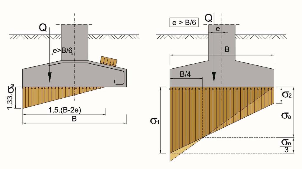
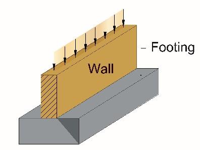
3 Foundations under walls or under closely spaced rows of columns sometimes require a specific type of foundation, such as cantilever and balanced footings and strip footings. Pad footing Square or rectangular footing supporting a single column. Strip footing Long footing supporting a continuous wall. Combined footing Footing supporting two or more columns. Balanced footing Footing supporting two columns, one of which lies at or near one end. Raft Foundation supporting a number of columns or loadbearing walls so as to transmit approximately uniform loading to the soil. Pile cap Foundation in the form of a pad, strip, combined or balanced footing in which the forces are transmitted to the soil through a system of piles. The plan area of the foundation should be proportioned on the following assumptions: a. All forces are transmitted to the soil without exceeding the allowable bearing pressure b. When the foundation is axially loaded, the reactions to design loads are uniformly distributed per unit area or per pile. A foundation may be treated as axially loaded if the eccentricity does not exceed 0.02 times the length in that direction c. When the foundation is eccentrically loaded, the reactions vary linearly across the footing or across the pile system. Footings should generally be so proportioned that zero pressure occurs only at one edge. It should be noted that eccentricity of load can arise in two ways: the columns being located eccentrically on the foundation; and/or the column transmitting a moment to the foundation. Both should be taken into account and combined to give the maximum eccentricity. d. All parts of a footing in contact with the soil should be included in the assessment of contact pressure e. It is preferable to maintain a reasonably similar pressure under all foundations to avoid significant differential settlement.

4 3.9.1 Shallow Foundations A shallow foundation distributes loads from the building into the upper layers of the ground. Shallow foundations are susceptible to any seismic effect that changes the ground contour, such as settlement or lateral movement. Such foundations are suitable when these upper soil layers have sufficient strength ( bearing capacity ) to carry the load with an acceptable margin of safety and tolerable settlement over the design life. The different types of shallow foundation are: a) Strip footing b) Spread or isolated footing c) Combined footing Strap or cantilever footing d) Mat or raft Foundation.


5 Punching in Spread Footing Figure: Shallow Foundations Figure: Spread Footing Design of Reinforcement

6 Figure: Figure:


7 Figure: Figure: Strap Footing It consists of two isolated footings connected with a structural strap or a lever, as shown in figure The strap connects the footing such that they behave as one unit. The strap simply acts as a connecting beam. A strap footing is more economical than a combined footing when the allowable soil pressure is relatively high and distance between the columns is large.

8 Figure: Figure: Figure:


9 3.9.3 Combined Footing It supports two columns as shown in fig It is used when the two columns are so close to each other that their individual footings would overlap. A combine footing may be rectangular or trapezoidal in plan. Trapezoidal footing is provided when the load on one of the columns is larger than the other column. Figure: Combined Footing Strip/continuous footings A strip footing is another type of spread footing which is provided for a load bearing wall. A strip footing can also be provided for a row of columns which are so closely spaced that their spread footings overlap or nearly touch each other. In such a cases, it is more economical to provide a strip footing than to provide a number of spread footings in one line. A strip footing is also known as continuous footing.


10 Figure: A traditional strip foundation consists of a minimum thickness of 150 mm of concrete placed in a trench, typically m wide. Reinforcement can be added if a wider strip is required to bridge over soft spots at movement joints or changes in founding strata. Figure: Mat or Raft footings It is a large slab supporting a number of columns and walls under entire structure or a large part of the structure. A mat is required when the allowable soil pressure is low or where the columns and walls are so close that individual footings would overlap or nearly touch each other. Mat foundations are useful in reducing the differential settlements on non-homogeneous soils or where there is large variation in the loads on individual columns. Figure:

11 Figure: Pile foundations Deep foundations are used when the soil at foundation level is inadequate to support the imposed loads with the required settlement criterion. Where the bearing capacity of the soil is poor or the imposed load are very heavy, piles, which may be square, circular or other shapes are used for foundations. If no soil layer is available, the pile is driven to a depth such that the load is supported through the surface friction of the pile. The piles can be precast or cast in situ. Deep foundations act by transferring loads down to competent soil at depth and/or by carrying loading by frictional forces acting on the vertical face of the pile. Diaphragm walls, contiguous bored piles and secant piling methods are covered later in this chapter. Short-bored piles have been used on difficult ground for low-rise construction for many years. They can be designed to carry loads with limited settlements, or to reduce total or differential settlements. They can have bases that are flat, pointed or bulbous, and shafts that are vertical or raked. In some circumstances, piles can be constructed of other materials, such as timber or plastics. Piled walls or sheet piles are used to resist lateral movements, such as in forming a basement.
 piles and driven (or displacement) piles. Figure: 3.9.")

12 The piling technique used to install the piles will be determined by the ground conditions, loading requirements for the final pile as well as other factors such as access or proximity to other buildings and the need for noise reduction. Pile types There are two basic types of piles: cast-in-place (or replacement) piles and driven (or displacement) piles. Figure: Figure: Piles are individual columns, generally constructed of concrete or steel, that support loading through a combination of friction on the pile shaft and end-bearing on the pile toe. The distribution of load carried by each mechanism is a function of soil type, pile type and settlement. They can also be used to resist imposed loading caused by the movement of the surrounding soil, such as vertical movements of shrinking and swelling soils. Piles can be installed vertically or may be raked to support different loading configurations.


13 Figure: All pile caps should generally be reinforced in two orthogonal directions on the top and bottom faces and the amount of reinforcement should not be less than bh in each direction. The bending moments and the reinforcement should be calculated on critical sections at the column faces, assuming that the pile loads are concentrated at the pile centres. This reinforcement should be continued past the piles and bent up vertically to provide full anchorage past the centreline of each pile. Figure:

14 Figure: Figure:


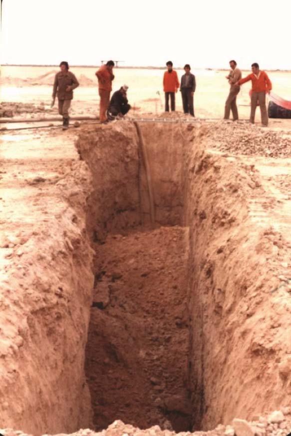
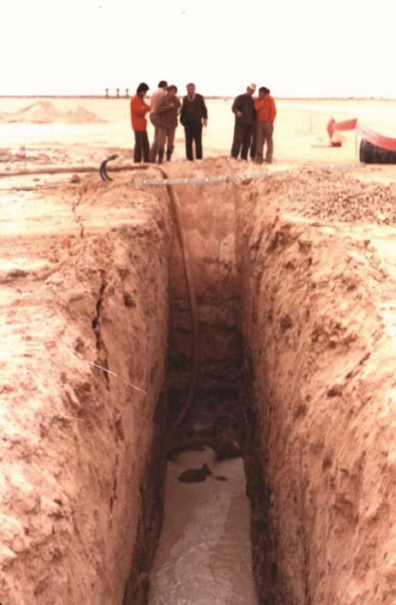
15 Figure : collapse of unbearable soil

16 Figure : Main reinforcement in slab foundation Example 3.9-1: Assessment of slab foundation to punching Depth of the reinforced slab foundation: h d 80cm Tensile strength of concrete: f ctm 0.9MPa Width of column: b s 50cm Height of column: h s 40cm Design strength of reinforcement: f yd 375MPa Figure: Perimeter of critical cross-section: h s h d 2 u cr b s h d u cr 5m

17 Shearing force carrying by concrete: Q bu 0.42h d f ctm u cr Q bu 1512 kn P kN P P 1 Q bu P 1188kN Required surface area of reinforcement to punching: A sb P A sb m f yd Reinforcement diameter: 2 25mm A s1 A s m 2 4 Number of profiles: A sb n n Q 0.42h d f ctm u cr Q 1512kN A s1 Figure: Data of rolled I profiles: I28 A mm 2 J1y mm 4 h 1 280mm
18 b 1 119mm b 2 119mm b 3 119mm I34 A mm 2 J1y mm 4 h 1 340mm b 1 137mm b 2 137mm b 3 137mm I38 A mm 2 J1y mm 4 h 1 380mm b 1 149mm b 2 149mm b 3 149mm h 2 20mm h 3 20mm L 1.45m P p 1 p kn M p L M mkN 8 3 b 2 h 3 2 b A 2 b 2 h 2 A 3 b 3 h 3 J 2 3 h 3 J h 1 h 2 h 3 A 1 h 2 A 2 A 3 h 1 h e 2 e m A 1 A 2 A 3 H h 1 h 2 h 3 H 0.42m e 1 H e 2 e m h 1 h 2 a 1 h 2 e 2 a 2 e 2 a 3 H h 3 e 2 a 1 0 m The total moment of inertia of composite section: J J1y J 2 J 3 A 1 a 1 A 2 a 2 A 3 a 3 J m 4 J J1y

19 Figure: Section modulus: W d J W d m 3 J W h W h m 3 e 1 Stress control: d h M d 70.86MPa s 210MPa W d M h MPa s 210MPa W h e 2
20 Example 3.9-2: Determination of the design bearing capacity of the soil at depth dp =1,5 m Soli classification F6: c ef c ef 16kPa ef 21deg c d 2 d ef m Bearing coefficient of the soil: N d tan 45deg d 2 2 e tan d N b 1.5 N d 1 tan d N c 2 m ef ef 4deg 1 21 kn m Base area of the footing: Width: bp = 1 m Length: Lp = 6 m Coefficient of the shape of the footing: s c b p b p s d 1 sin d s b b p d c l p l p l p d p b p d p d d sin2 d i d 1 i c 1 i b 1 b p Design bearing capacity of the soil: R d c d N c s c d c i c 1 d p b p N d s d d d i d 2 N b s b d b i b R d k 2
Types of Foundations
 Shallow Foundations Types of Foundations Foundations can be classified to two major categories: Shallow. Deep. 1 Introduction If the soil stratum is suitable for supporting the structural loads from the
Building Construction
 Building Construction Shallow Foundations Module-III Introduction The foundation can be classified broadly into two types: Shallow foundations Deep foundations Shallow foundations Shallow Foundations When
twenty four foundations and retaining walls Foundation Structural vs. Foundation Design Structural vs. Foundation Design
 ALIED ARCHITECTURAL STRUCTURES: STRUCTURAL ANALYSIS AND SYSTEMS DR. ANNE NICHOLS SRING 2018 lecture twenty four Foundation the engineered interface between the earth and the structure it supports that
twenty six concrete construction: foundation design ELEMENTS OF ARCHITECTURAL STRUCTURES: FORM, BEHAVIOR, AND DESIGN DR. ANNE NICHOLS SPRING 2013
 ELEMENTS OF ARCHITECTURAL STRUCTURES: FORM, BEHAVIOR, AND DESIGN DR. ANNE NICHOLS SPRING 2013 lecture twenty six concrete construction: www.tamu.edu foundation design Foundations 1 Foundation the engineered
Foundation or Footing Design: Part 1
 Foundation or Footing Design: Part 1 Foundation or Footing Footings are structural elements that transmit column or wall loads to the underlying soil below the structure. Footings are designed to transmit
twenty seven concrete construction: foundation design Foundation Structural vs. Foundation Design Structural vs. Foundation Design
 ARCHITECTURAL STRUCTURES: FORM, BEHAVIOR, AND DESIGN DR. ANNE NICHOLS SRING 2017 lecture twenty seven Foundation the engineered interface between the earth and the structure it supports that transmits
Combined footings A mat or raft or floating foundation Pile caps
 Foundation or Footing Design: Part 1 Courtesy of Dr. Latifee s IMI research group, Text books (Design of concrete structures by McCormac etc.) and others Foundation or Footing Footings are structural elements
FOUNDATION ENGINEERING UNIT III FOOTINGS AND RAFTS
 1 FOOTINGS AND RAFTS FOUNDATION ENGINEERING UNIT III Types of foundation Contact pressure distribution below footings & raft - Isolated and combined footings types proportioning - mat foundation types
ST7008 PRESTRESSED CONCRETE
 ST7008 PRESTRESSED CONCRETE QUESTION BANK UNIT-I PRINCIPLES OF PRESTRESSING PART-A 1. Define modular ratio. 2. What is meant by creep coefficient? 3. Is the deflection control essential? Discuss. 4. Give
Lesson 2 Substructure. Dr S.Sreenath BSc Engg, MSc Engg, MSc (ICM), MBA, PhD
, MBA, PhD") Lesson 2 Substructure Dr S.Sreenath BSc Engg, MSc Engg, MSc (ICM), MBA, PhD Outline Syllabus 1. Demolition 2. Site problems 3. Substructure 4. Basements 5. Structural Frames 6. Floors 7. External walls
Lesson 2 Substructure Dr S.Sreenath BSc Engg, MSc Engg, MSc (ICM), MBA, PhD Outline Syllabus 1. Demolition 2. Site problems 3. Substructure 4. Basements 5. Structural Frames 6. Floors 7. External walls
DHANALAKSHMI COLLEGE OF ENGINEERING, CHENNAI DEPARTMENT OF CIVIL ENGINEERING 2 MARK QUESTIONS WITH ANSWERS CE FOUNDATION ENGINEERING UNIT 1
 DHANALAKSHMI COLLEGE OF ENGINEERING, CHENNAI DEPARTMENT OF CIVIL ENGINEERING 2 MARK QUESTIONS WITH ANSWERS CE6502 - FOUNDATION ENGINEERING Subject Code: CE6502 UNIT 1 1. What are the informations obtained
APPROXIMATE ANALYSIS OF PILED RAFT. Rameez Gahlot1, Roshni J John2
 APPROXIMATE ANALYSIS OF PILED RAFT Rameez Gahlot1, Roshni J John2 1 PG Student, Dept of Civil Engg, Saraswati College of Engineering, Kharghar-4121, India rameezgahlot@gmail.com.2 Head of Civil Engineering
Foundation Design. π = pi ( radians or 180 ) ρ = reinforcement ratio in concrete beam design = A s /bd µ = coefficient of static friction
 ρ = reinforcement ratio in concrete beam design = A s /bd µ = coefficient of static friction") Foundation Design Notation: a = name for width dimension A = name for area b = width of retaining wall stem at base = width resisting shear stress b o = perimeter length for two-way shear in concrete footing
Foundation Design Notation: a = name for width dimension A = name for area b = width of retaining wall stem at base = width resisting shear stress b o = perimeter length for two-way shear in concrete footing
Seven Wonders of the Ancient World
 Seven Wonders of the Ancient World Pyramid of Meidum shed 250,000 tons of limestone outer casings Typical Pyramid Pyramid at Meidum Mexico Alameda buildings Palace of Fine Arts National Theater
DESIGN OF RC ELEMENTS UNIT 1 PART-A
 DESIGN OF RC ELEMENTS UNIT 1 PART-A 1. Calculate the design strength for M 30 grade concrete and Fe 415 grade steel? 2. What is the important principle of ultimate load method? 3. Write the classification
Contents. Foreword 1 Introduction 1
 Contents Notation x Foreword xiii 1 Introduction 1 1.1 Aims of the Manual 1 1.2 Eurocode system 1 1.3 Scope of the Manual 3 1.4 Contents of the Manual 4 1.5 Notation and terminology 4 2 General principles
Earth Retaining Walls CIVL455 CHAPTER I: INTRODUCTION
 Earth Retaining Walls CIVL455 CHAPTER I: INTRODUCTION Earth retaining structures are designed to overcome significant variation in ground levels to provide either a sloping or flat ground on the retained
Section 1: Summary and recommendations Volumes 1 3
 Section 1: Summary and recommendations Volumes 1 3 Volume 1: Seismicity, soils and the seismic design of buildings Section 2: Seismicity In this section the Royal Commission discusses the forces giving
Downloaded from Downloaded from /1
 PURWANCHAL UNIVERSITY VI SEMESTER FINAL EXAMINATION-2003 LEVEL : B. E. (Civil) SUBJECT: BEG359CI, Foundation Engineering. Full Marks: 80 TIME: 03:00 hrs Pass marks: 32 Candidates are required to give their
4.6 Procedures for Connections
 4.6 Procedures for Connections This section provides Tier 2 evaluation procedures that apply to structural connections: anchorage for normal forces, shear transfer, vertical components, interconnection
BS EN :2004 EN :2004 (E)
") Contents List 1. General 1.1 Scope 1.1.1 Scope of Eurocode 2 1.1.2 Scope of Part 1-1 of Eurocode 2 1.2 Normative references 1.2.1 General reference standards 1.2.2 Other reference standards 1.3 Assumptions
Contents List 1. General 1.1 Scope 1.1.1 Scope of Eurocode 2 1.1.2 Scope of Part 1-1 of Eurocode 2 1.2 Normative references 1.2.1 General reference standards 1.2.2 Other reference standards 1.3 Assumptions
Foundation Engineering ECIV 4352
 Foundation Engineering ECIV 4352 Instructor : Dr. Jehad Hamad 2016-2015 Chapter (11) Deep Foundation Chapter 11 Pile Foundation Foundation- Design Considerations Factors to be taken into consideration
Assalamualaikum & Good Morning (May All Of You Gain A Better Understanding)
") Assalamualaikum & Good Morning (May All Of You Gain A Better Understanding) Always Try To Do The Best In Your Life TYPES OF FOUNDATION TYPES OF FOUNDATION a) Shallow Foundation System i) Spread Foundation
Assalamualaikum & Good Morning (May All Of You Gain A Better Understanding) Always Try To Do The Best In Your Life TYPES OF FOUNDATION TYPES OF FOUNDATION a) Shallow Foundation System i) Spread Foundation
Analysis and Design of a Multi-storey Reinforced Concrete Building
 United Arab Emirates University College of Engineering Civil and Environmental Engineering Department Graduation Project II 1 Analysis and Design of a Multi-storey Reinforced Concrete Building Prepared
7th task: Pad footing
 7th task: Pad footing Pad footing Design of dimensions Design of plain concrete pad footing Design of reinforced concrete pad footing Drawings (shape and reinforcement of footings) Difference between PC/RC
2016 DESIGN AND DRAWING OF REINFORCED CONCRETE STRUCTURES
 R13 SET - 1 DESIGN AND DRAWING OF REINFCED CONCRETE STRUCTURES 1 Design a simply supported rectangular beam to carry 30kN/m superimposed load over a span of 6m on 460mm wide supports. Use M20 grade concrete
Civil Engineering Construction I (CBE5031)
") Civil Engineering Construction I (CBE5031) Basement 1 1 Quick Revision 1.1 Problems arising from basement construction a) Excavation method. b) Surface and ground water control c) Lateral stability of
Civil Engineering Construction I (CBE5031) Basement 1 1 Quick Revision 1.1 Problems arising from basement construction a) Excavation method. b) Surface and ground water control c) Lateral stability of
Construction Technology B (CON4313)
") 3 - Basement 1 Quick Revision 1.1 Problems arising from basement construction a. Excavation method. b. Surface and ground water control c. Lateral stability of basement excavation. d. Stability of adjoining
3 - Basement 1 Quick Revision 1.1 Problems arising from basement construction a. Excavation method. b. Surface and ground water control c. Lateral stability of basement excavation. d. Stability of adjoining
A Guide for the Interpretation of Structural Design Options for Residential Concrete Structures
 CFA Technical Note: 008-2010 A Guide for the Interpretation of Structural Design Options for Residential Concrete Structures CFA Technical This CFA Technical Note is intended to serve as a guide to assist
Contents. Glossary 9. Foreword 10
 Glossary 9 Foreword 10 1 Design considerations 11 1.1 Introduction 11 1.2 Client's general requirements 11 1.3 The ground 11 1.3.1 The concept of effective stress 11 1.3.2 Ground profile 13 1.3.3 Groundwater
 techie-touch.blogspot.com www.vidyarthiplus.com CE2305 FOUNDATION ENGINEERING 2 MARKS QUESTIONS & ANSWERS 16 MARKS QUESTIONS UNIT -1 1. What are components of total foundation settlement? elastic settlement,
Masonry and Cold-Formed Steel Requirements
 PC UFC Briefing September 21-22, 2004 Masonry and Cold-Formed Steel Requirements David Stevens, ARA Masonry Requirements Composite Construction Masonry is often used in composite construction, such as
UNDERPINNING A CRANE FOUNDATION
 UNDERPINNING A CRANE FOUNDATION Donald R. McMahon, P.E., McMahon & Mann Consulting Engineers, P.C., Buffalo, New York, USA Andrew J. Nichols, P.E., McMahon & Mann Consulting Engineers, P.C., Buffalo, New
Misan University - College of Engineering Civil Engineering Department
 CHAPTER 2 Soil and Excavations Soil investigation including two phases: surface investigation and subsurface investigation Surface investigation involves making a preliminary judgment about the site s
Modeling and Design of Bridge Super Structure and Sub Structure
 Topic 3 Day 2 Modeling and Design of Bridge Super Structure and Sub Structure Naveed Anwar 1. Over view of Bridge Design Process and Bridge Types 2. Advances and recent trends in Modeling and Analysis
ASSIGNMENT 1 ANALYSIS OF PRESTRESS AND BENDING STRESS BFS 40303
 Instruction : Answer all question ASSIGNMENT 1 ANALYSIS OF PRESTRESS AND BENDING STRESS BFS 40303 1. A rectangular concrete beam, 100 mm wide by 250 mm deep, spanning over 8 m is prestressed by a straight
A seismic engineer s note book
 A seismic engineer s note book G.R. Houston, A.S. Beer, G.L. Cole & R.D. Jury Beca Ltd, New Zealand. 2014 NZSEE Conference ABSTRACT: The interest in seismic retrofit of buildings stimulated by the Canterbury
Level 6 Graduate Diploma in Engineering Structural analysis
 9210-111 Level 6 Graduate Diploma in Engineering Structural analysis Sample Paper You should have the following for this examination one answer book non-programmable calculator pen, pencil, ruler, drawing
CHAPTER 2. Design Formulae for Bending
 CHAPTER 2 Design Formulae for Bending Learning Objectives Appreciate the stress-strain properties of concrete and steel for R.C. design Appreciate the derivation of the design formulae for bending Apply
UNIT-1 RETAINING WALLS
 UNIT-1 RETAINING WALLS PART-A 1. Describe about Retaining wall. 2. Define gravity retaining walls. BT-1 3. Classify the types of retaining walls. 4. Explain cantilever retaining wall? 5. Describe about
CHAPTER 11 Bar Cutoff
 page 188 CHAPTER 11 11.1. Anchorage of Tension Bars by Hooks In the event that the desired tensile stress in a bar cannot be developed by bond alone, it is necessary to provide special anchorage at the
SECANT PILE. Introduction:
 SECANT PILE Introduction: Over the last few decades construction of retaining walls in urban areas has grown significantly, as a result of territorial and economical development of the cities. In most
An Introduction to Spread Footings and Mat Foundations
 An Introduction to Spread Footings and Mat Foundations J. Paul Guyer, P.E., R.A. Editor Paul Guyer is a registered civil engineer, mechanical engineer, fire protection engineer, and architect with over
Steel screw settlement reduction piles for a raft foundation on soft soil
 Proc. 18 th NZGS Geotechnical Symposium on Soil-Structure Interaction. Ed. CY Chin, Auckland Alexei Murashev Opus International Consultants Limited, Wellington, New Zealand. Keywords: piled raft, settlement
SIDDHARTH GROUP OF INSTITUTIONS :: PUTTUR Siddharth Nagar, Narayanavanam Road QUESTION BANK (DESCRIPTIVE) UNIT-5 FOOTINGS & STAIRS
 UNIT-5 FOOTINGS & STAIRS") SIDDHARTH GROUP OF INSTITUTIONS :: PUTTUR Siddharth Nagar, Narayanavanam Road 517583 QUESTION BANK (DESCRIPTIVE) Subject with Code : DDRCS(13A01502) Year & Sem: III-B.Tech & I-Sem Course & Branch: B.Tech
SIDDHARTH GROUP OF INSTITUTIONS :: PUTTUR Siddharth Nagar, Narayanavanam Road 517583 QUESTION BANK (DESCRIPTIVE) Subject with Code : DDRCS(13A01502) Year & Sem: III-B.Tech & I-Sem Course & Branch: B.Tech
Precast concrete is significantly being used in earthquake
 Structural Connections for Precast Concrete Buildings - Review of Seismic and Other Design Provisions in Various International Codes - An Overview 1 2 C.A Prasad 1, Pavan Patchigolla 2 1 Director, METEY
ANNEX 10. Special requirements recommended for structures subject to seismic actions. 1 Scope. 2 Basis of design. 2.1 Fundamental requirements
 ANNEX 10 Special requirements recommended for structures subject to seismic actions 1 Scope This Annex sets out the special requirements which are recommended for structural concrete structures subject
Possible solution to past CM exam question. Question 2 July New city centre office block. by Rajavel Inbarajan
 Possible solution to past CM exam question Question 2 July 2015 New city centre office block by Rajavel Inbarajan The information provided should be seen as an interpretation of the brief and a possible
mortarless masonry Design Manual Part 1 (IS 456:2000) Section 1 Page 1 IS 456:2000 PLAIN AND REINFORCED CONCRETE - CODE OF PRACTICE
 Section 1 Page 1 IS 456:2000 PLAIN AND REINFORCED CONCRETE - CODE OF PRACTICE") SECTION 1. mortarless masonry Design Manual Part 1 (IS 456:2000) Section 1 Page 1 1.1 Overview of IS 456:2000 IS 456:2000 PLAIN AND REINFORCED CONCRETE - CODE OF PRACTICE IS 456:2000 is the current Indian
SECTION 1. mortarless masonry Design Manual Part 1 (IS 456:2000) Section 1 Page 1 1.1 Overview of IS 456:2000 IS 456:2000 PLAIN AND REINFORCED CONCRETE - CODE OF PRACTICE IS 456:2000 is the current Indian
VARIOUS TYPES OF SLABS
 VARIOUS TYPES OF SLABS 1 CHOICE OF TYPE OF SLAB FLOOR The choice of type of slab for a particular floor depends on many factors. Economy of construction is obviously an important consideration, but this
Interaction between ductile RC perimeter frames and floor slabs containing precast units
 Interaction between ductile RC perimeter frames and floor slabs containing precast units R. C Fenwick,. J. Davidson and D.. N. Lau Department of Civil and Environmental Engineering, University of uckland.
Design and analysis of deep beams, plates and other discontinuity regions BJÖRN ENGSTRÖM. q l (SLS) d ef. T SLS A ef. Tie = reinforced concrete Aef
 d ef. T SLS A ef. Tie = reinforced concrete Aef") q l (SLS) d ef T SLS A ef Tie = reinforced concrete Aef Design and analysis of deep beams, plates and other discontinuity regions BJÖRN ENGSTRÖM Department of Civil and Environmental Engineering Division
q l (SLS) d ef T SLS A ef Tie = reinforced concrete Aef Design and analysis of deep beams, plates and other discontinuity regions BJÖRN ENGSTRÖM Department of Civil and Environmental Engineering Division
1 Prepared By:Mr.A.Sathiyamoorthy, M.E., AP/Civil
 UNIVERSITY QUESTIONS PART A UNIT 1: INTRODUCTION THEORY AND BEHAVIOUR 1. List the loss of prestress. 2. Define axial prestressing. 3. What is the need for the use of high strength concrete and tensile
Pile foundations Introduction
 Engineering manual No. 12 Updated: 06/2018 Pile foundations Introduction Program: Pile, Pile CPT, Pile Group The objective of this engineering manual is to explain the practical use of programs for the
Footings GENERAL CONSIDERATIONS 15.2 LOADS AND REACTIONS 15.4 MOMENT IN FOOTINGS
 4 Footings GENERAL CONSIDERATIONS Provisions of Chapter 15 apply primarily for design of footings supporting a single column (isolated footings) and do not provide specific design provisions for footings
Issues on Design of Piled Raft Foundation
 IOSR Journal of Mechanical and Civil Engineering (IOSR-JMCE) e-issn: 2278-1684,p-ISSN: 2320-334X, Volume 14, Issue 2 Ver. I (Mar. - Apr. 2017), PP 36-40 www.iosrjournals.org Issues on Design of Piled Raft
EFFECT OF DEEP EXCAVATION SUPPORTED BY CONCRETE SOLIDER PILE WITH STEEL SHEET PILE LAGGING WALL ON ADJACENT EXISTING BUILDINGS
 EFFECT OF DEEP EXCAVATION SUPPORTED BY CONCRETE SOLIDER PILE WITH STEEL SHEET PILE LAGGING WALL ON ADJACENT EXISTING BUILDINGS Mostafa Abdou 1 *, Ahamed Rushedy Towfeek 2, Waleed Hassan 3 1 prof. Dr.,
The Bearing Capacity of Soils. Dr Omar Al Hattamleh
 The Bearing Capacity of Soils Dr Omar Al Hattamleh Example of Bearing Capacity Failure Omar Play the move of bearing Capacity failure The Philippine one Transcona Grain Silos Failure - Canada The Bearing
OXFORD ENGINEERING COLLEGE (NAAC Accredited with B Grade) Department of Civil Engineering LIST OF QUESTIONS
 Department of Civil Engineering LIST OF QUESTIONS") OXFORD ENGINEERING COLLEGE (NAAC Accredited with B Grade) Department of Civil Engineering LIST OF QUESTIONS Year/ Sem. : IV / VII Staff Name : S.LUMINA JUDITH Subject Code : CE 6702 Sub. Name : PRE STRESSED
OXFORD ENGINEERING COLLEGE (NAAC Accredited with B Grade) Department of Civil Engineering LIST OF QUESTIONS Year/ Sem. : IV / VII Staff Name : S.LUMINA JUDITH Subject Code : CE 6702 Sub. Name : PRE STRESSED
SIDDHARTH GROUP OF INSTITUTIONS :: PUTTUR Siddharth Nagar, Narayanavanam Road QUESTION BANK (DESCRIPTIVE)
") SIDDHARTH GROUP OF INSTITUTIONS :: PUTTUR Siddharth Nagar, Narayanavanam Road 517583 QUESTION BANK (DESCRIPTIVE) Subject with Code : DDRCS(13A01502) Year & Sem: III-B.Tech & I-Sem Course & Branch: B.Tech
SIDDHARTH GROUP OF INSTITUTIONS :: PUTTUR Siddharth Nagar, Narayanavanam Road 517583 QUESTION BANK (DESCRIPTIVE) Subject with Code : DDRCS(13A01502) Year & Sem: III-B.Tech & I-Sem Course & Branch: B.Tech
Chapter 2 Notation and Terminology
 Reorganized 318 Chapter Titles Chapter 1 General 1.1 Scope 1.2 Purpose 1.3 Interpretation 1.4 Drawings and Specifications 1.5 Testing and Inspection 1.6 Administatration and Enforcement 1.6.1 Retention
CADS A3D MAX. How to model shear walls
 CADS A3D MAX How to model shear walls Modelling shear walls in A3D MAX Introduction and synopsis This paper explains how to model shear walls in A3D MAX using the `wide column rigid arm sub-frame described
FOUNDATION ENGINEERING UNIT -1 SITE INVESTIGATION & SELECTION OF FOUNDATION 1. What are components of total foundation settlement?
 FOUNDATION ENGINEERING UNIT -1 SITE INVESTIGATION & SELECTION OF FOUNDATION 1. What are components of total foundation settlement? Elastic settlement, consolidation settlement, secondary consolidation
This document downloaded from vulcanhammer.net vulcanhammer.info Chet Aero Marine
 This document downloaded from vulcanhammer.net vulcanhammer.info Chet Aero Marine Don t forget to visit our companion site http://www.vulcanhammer.org Use subject to the terms and conditions of the respective
Comparison of One-way and Two-way slab behavior. One-way slabs carry load in one direction. Two-way slabs carry load in two directions.
 Two-way Slabs Comparison of One-way and Two-way slab behavior One-way slabs carry load in one direction. Two-way slabs carry load in two directions. Comparison of One-way and Two-way slab behavior One-way
BEARING CAPACITY IMPROVEMENT USING MICROPILES A CASE STUDY
 BEARING CAPACITY IMPROVEMENT USING MICROPILES A CASE STUDY G.L. Sivakumar Babu 1, B. R.Srinivasa Murthy 2, D.S. N. Murthy 3, M.S. Nataraj 4 ABSTRACT Micropiles have been used effectively in many applications
Lecture Retaining Wall Week 12
 Lecture Retaining Wall Week 12 Retaining walls which provide lateral support to earth fill embankment or any other form of material which they retain them in vertical position. These walls are also usually
FOUNDATIONS. Foundations Copyright G G Schierle, 2006 Press Esc to end, for next, for previous slide 1
 FOUNDATIONS Foundations Copyright G G Schierle, 2006 Press Esc to end, for next, for previous slide 1 Liquefaction reduced the soil strength under these apartment buildings in Niigata (Japan) 1964. Liquefaction
REINFORCED CONCRETE DESIGN
 REINFORCED CONCRETE DESIGN Other Macmillan titles of related interest Microcomputer Applications in Structural Engineering W. H. Mosley and W. J. Spencer Reinforced Concrete Design by Computer R. Hulse
This final draft of the fib MC2010 has not been published; it is intended only for the purpose of voting by the General Assembly.
 7 Design 382 In the case of combined action of torsion, bending and shear force in a solid section, the core within the idealised hollow cross-section may be used for the transmission of the shear forces.
Design & Seismic Detailing of Nonstandard Deep Precast Concrete Box Girders For Long Span Railroad Bridges By:
 Design & Seismic Detailing of Nonstandard Deep Precast Concrete Box Girders For Long Span Railroad Bridges By: ABSTRACT Shafi M. Sharifan, Ph.D., P.E. Wei Koo & Associates Orange, California Kosal Krishnan,
10-COLUMNS: 10.1 Introduction.
 1 10-COLUMNS: 10.1 Introduction. Columns are vertical compression members of a structural frame intended to support the loadcarrying beams. They transmit loads from the upper floors to the lower levels
CIVL473 Fundamentals of Steel Design
 CIVL473 Fundamentals of Steel Design CHAPTER 3 Design of Beams Prepared By Asst.Prof.Dr. Murude Celikag DESIGN OF STRUCTURAL ELEMENTS 3. Beams in Buildings 3.1. Laterally Restrained Beams Restrained beams
Modjeski and Masters, Inc. Consulting Engineers 04/18/06 St. Croix River Bridge 3D Analysis Report Introduction
 Introduction This memo presents a summary of a three dimensional (3D) analysis of the Organic concept for the proposed St. Croix River bridge project. The Organic concept has several attributes that are
Comparative Study of R.C.C and Steel Concrete Composite Structures
 RESEARCH ARTICLE OPEN ACCESS Comparative Study of R.C.C and Steel Concrete Composite Structures Shweta A. Wagh*, Dr. U. P. Waghe** *(Post Graduate Student in Structural Engineering, Y.C.C.E, Nagpur 441
Sabah Shawkat Cabinet of Structural Engineering 2017
 3.3 Staircases Staircases provide means of movement from one floor to another in a structure. The effective span of a simply supported slab should normally be taken as the clear distance between the faces
Ductile Detailing for Earthquake Resistant R C Structures. Dr. S. K. PRASAD Professor of Civil Engineering S.J. College of Engineering Mysore
 Ductile Detailing for Earthquake Resistant R C Structures Dr. S. K. PRASAD Professor of Civil Engineering S.J. College of Engineering Mysore 570 006 1 Ductile Detailing Objective To provide adequate toughness
Schöck Isokorb Type CM
 Schöck Isokorb Type Schöck Isokorb Type The Schöck Isokorb Type is suitable for cantilevered reinforced concrete slabs. (C for concrete slab) It transmits negative moment (M) and positive shear force.
VOLUNTARY - EARTHQUAKE HAZARD REDUCTION IN EXISTING HILLSIDE BUILDINGS (Division 94 Added by Ord. No. 171,258, Eff. 8/30/96.)
") DIVISION 94 VOLUNTARY - EARTHQUAKE HAZARD REDUCTION IN EXISTING HILLSIDE BUILDINGS (Division 94 Added by Ord. No. 171,258, Eff. 8/30/96.) SEC. 91.9401. PURPOSE. (Amended by Ord. No. 172,592, Eff. 6/28/99,
DIVISION 94 VOLUNTARY - EARTHQUAKE HAZARD REDUCTION IN EXISTING HILLSIDE BUILDINGS (Division 94 Added by Ord. No. 171,258, Eff. 8/30/96.) SEC. 91.9401. PURPOSE. (Amended by Ord. No. 172,592, Eff. 6/28/99,
CHAPTER 8. Concrete Work
 Concrete Work Clay Bricklaying Made Easy CONCRETE WORK Foundations for walls and piers All loadbearing walls and piers are required to stand on a concrete foundation, which must be able to receive and
Case Histories in Geotechnical Engineering
 Fourth International Conference on Case Histories in Geotechnical Engineering March 8 12, 1998, St. Louis, Missouri, USA Editor : Shamsher Prakash Prediction and performances of short embedded cast in-situ
Soil Mechanics Lateral Earth Pressures page Lateral Earth Pressures in case of inclined ground surface or friction at wall-ground interface
 Soil Mechanics Lateral Earth Pressures page 9 7.6 Lateral Earth Pressures in case of inclined ground surface or friction at wall-ground interface By now, we have considered the wall as perfectly smooth
Earthquake Design of Flexible Soil Retaining Structures
 Earthquake Design of Flexible Soil Retaining Structures J.H. Wood John Wood Consulting, Lower Hutt 207 NZSEE Conference ABSTRACT: Many soil retaining wall structures are restrained from outward sliding
SEISMIC SOIL-STRUCTURE INTERACTION IN FULLY INTEGRAL ABUTMENT BRIDGES WITH HP STEEL PILES
 SEISMIC SOIL-STRUCTURE INTERACTION IN FULLY INTEGRAL ABUTMENT BRIDGES WITH HP STEEL PILES YU BAO 1 and ANDREW RIETZ 2 1 : Assistant Professor, Department of Civil Engineering Technology, Environmental
Compressibility of Soil. Chapter 11
 Compressibility of Soil Chapter 11 TOPICS INTRODUCTION ELASTIC SETTLEMENT Stress distribution in soil masses CONSOLIDATION SETTLEMENT Fundamentals of consolidation Calculation of 1-D Consolidation Settlement
Table of Contents 18.1 GENERAL Overview Responsibilities References
 Table of Contents Section Page 18.1 GENERAL... 18.1-1 18.1.1 Overview... 18.1-1 18.1.2 Responsibilities... 18.1-1 18.1.3 References... 18.1-2 18.2 MISCELLANEOUS FOUNDATION DESIGNS... 18.2-1 18.2.1 Buildings...
3.4.2 DESIGN CONSIDERATIONS
 3.4.2 DESIGN CONSIDERATIONS Formwork Where Flatdeck sheet is used as formwork, the profile provides resistance to wet concrete (G) and construction loads (Q). Maximum formwork spans given in Section 3.4.4.1
ARCH 331. Study Guide for Final Examination
 ARCH 331. Study Guide for Final Examination This guide is not providing answers for the conceptual questions. It is a list of topical concepts and their application you should be familiar with. It is an
SIDDHARTH GROUP OF INSTITUTIONS :: PUTTUR Siddharth Nagar, Narayanavanam Road QUESTION BANK (DESCRIPTIVE)
") SIDDHARTH GROUP OF INSTITUTIONS :: PUTTUR Siddharth Nagar, Narayanavanam Road 517583 QUESTION BANK (DESCRIPTIVE) Subject with Code :Strength of Materials-II (16CE111) Course & Branch: B.Tech - CE Year
SIDDHARTH GROUP OF INSTITUTIONS :: PUTTUR Siddharth Nagar, Narayanavanam Road 517583 QUESTION BANK (DESCRIPTIVE) Subject with Code :Strength of Materials-II (16CE111) Course & Branch: B.Tech - CE Year
Evaluation of negative skin friction on sheet pile walls at the Rio Grande dry dock, Brazil
 Geotechnical Aspects of Underground Construction in Soft Ground Viggiani (ed) 2012 Taylor & Francis Group, London, ISBN 978-0-415-68367-8 Evaluation of negative skin friction on sheet pile walls at the
Example of the Unified Design procedure for use in the September 8, 2014, short course on in Brazil
 Introduction Example of the Unified Design procedure for use in the September 8, 2014, short course on in Brazil The Unified Design procedure involves two main steps. The first is verifying that the loads
UNIT-I DESIGN CONCEPTS, DESIGN OF BEAMS Part - A (Short Answer Questions)
") S.NO IMPORTANT QUESTIONS UNIT-I DESIGN CONCEPTS, DESIGN OF BEAMS Part - A (Short Answer Questions) 1 What are the three methods of design of reinforced concrete structural elements? 2 State four objectives
S.NO IMPORTANT QUESTIONS UNIT-I DESIGN CONCEPTS, DESIGN OF BEAMS Part - A (Short Answer Questions) 1 What are the three methods of design of reinforced concrete structural elements? 2 State four objectives
Repute benchmarks. 4 x 4 pile group in firm to stiff clay. Results from Repute. Comparison with benchmark. Comments. Reference.
 4 x 4 pile group in firm to stiff clay 4 x 4 pile group embedded in firm to stiff clay, with an underlying rigid layer at 48m from ground level [1]. The piles are 24m long, 0.6m in diameter, and are spaced
Features and Benefits
 KingFlor KF40 Features and Benefits Fielders KF40 is a revolutionary steel formwork solution suitable for concrete slabs in all types of construction. KF40 combines the performance of a traditional flat
twenty two concrete construction: flat spanning systems, columns & frames ARCHITECTURAL STRUCTURES: FORM, BEHAVIOR, AND DESIGN
 ARCHITECTURAL STRUCTURES: FORM, BEHAVIOR, AND DESIGN DR. ANNE NICHOLS SUMMER 2014 lecture twenty two concrete construction: http:// nisee.berkeley.edu/godden flat spanning systems, columns & frames Concrete
Chapter. Masonry Design
 Chapter Masonry Design The masonry design section contains modules for the analysis of reinforced masonry beams subjected to pure bending and unreinforced masonry walls subjected to axial compression and