Bridge Deck Cracking Investigation and Repair
|
|
|
- Alfred Ferguson
- 6 years ago
- Views:
Transcription
1 UNF Digital Commons UNF Theses and Dissertations Student Scholarship 2012 Bridge Deck Cracking Investigation and Repair Vidal Velez Vargas University of North Florida Suggested Citation Vargas, Vidal Velez, "Bridge Deck Cracking Investigation and Repair" (2012). UNF Theses and Dissertations This Master's Thesis is brought to you for free and open access by the Student Scholarship at UNF Digital Commons. It has been accepted for inclusion in UNF Theses and Dissertations by an authorized administrator of UNF Digital Commons. For more information, please contact Digital Projects All Rights Reserved
2 BRIDGE DECK CRACKING INVESTIGATION AND REPAIR By: Vidal Velez Vargas B.S., University of North Florida, 2006 A thesis submitted to the Department of Civil Engineering in partial fulfillment of the requirement for the degree of Master of Science in Civil Engineering UNIVERSITY OF NORTH FLORIDA College of Computing, Engineering, and Construction April, 2012 Unpublished work c Vidal Velez Vargas
3 Signature Deleted Signature Deleted Signature Deleted Signature Deleted Signature Deleted Signature Deleted
4 Dedication I would like to thank all of those that helped me along the way with the research process and the completion of this thesis. First of all, thanks to my professors for the guidance, understanding, encouragement and wisdom imparted on me. I also extend my appreciation to Mr. Ivan Lasa and Mr. Mario Paredes from the Florida Department of Transportation for their cooperation. Thanks to all the undergraduate students that helped in the lab. To my fellow graduate students thank you for your support, patience, and assistance. Finally, but not least, to my wife Nancy V. Vargas, thank you for pushing me to pursue my Master s when I was down-and-out with no prospects of a career. Thanks for all the long hours spent waiting for my last test in the lab and thanks for being my best friend when I needed it the most. iv
5 TABLE OF CONTENTS LIST OF FIGURES... viii LIST OF TABLES x ABSTRACT.xi 1. INTRODUCTION Research Focus Report Organization Bridges Investigated Mechanism of Cracking in Hardened Concrete Transverse Cracks in Bridge Decks Causes of Transverse Cracking RESEARCH REVIEW CRACK SEALERS Sealer Products Material Characteristics and Performance Measures EXPERIMENTAL TESTING AND FIELD INVESTIGATION Lab Procedures for Materials and Testing Results Field Material Testing and Results RECOMMENDATIONS AND CONCLUSIONS SUMMARY Conclusions..68 APPENDIX A.70 APPENDIX B.84 APPENDIX C.89 REFERENCES 93 VITA..95 v
6 LIST OF FIGURES Figure 1-1 Bridge Deck Cracking...5 Figure 1-2 Corrosion Inside Box Beams Bridge Figure 1-3 Bridge Deck Cracking on Bridge Figure 1-4 Full Sections of Bridge 704 and its Cracking Pattern...10 Figure 1-5 Full Sections of Bridge 705 and its Cracking Pattern...11 Figure 1-6 Full Sections of Bridge 706 and its Cracking Pattern...12 Figure 1-7 Full Sections of Bridge 707 and its Cracking Pattern...13 Figure 1-8 Reinforcement on Bridge Figure 1-9 SIP Forms for Bridge Figure 1-10 Concrete Placement and Curing for Figure 1-11 Transverse Cracking Before Deck Grooves...15 Figure 1-12 Cracking after Deck Grooves...15 Figure 1-13 View of Bridge Figure 1-14 Deck Cracking and Sealing of Bridge Figure 1-15 Transverse Cracking of Bridge Figure 1-16 Cracking on Parapet Wall Bridge Figure 1-17 Core Sampling of Bridge Figure 1-18 Cause of Transverse Cracking on Bridge Decks...21 Figure 4-1 Preparing the Specimens for Testing...35 Figure 4-2 Applying the Sealant to Concrete Specimens and Testing...35 Figure 4-3 East-bound Section Divided into Six Test Areas...39 Figure 4-4 Clean-up of Bridge Figure 4-5 Sealer Application Bridge Figure 4-6 Sand Application for Skid Resistance Bridge Figure 4-7 Bridge Cores and Testing Procedure...41 Figure 4-8 Penetration Tests of Core Samples...44 Figure 4-9 Tensile Testing of Sealants...45 Figure 4-10 Sketch of Slab for Construction...47 Figure 4-11 Construction of Test Slabs and Placement of Blades for Crack Width...47 Figure 4-12 Blades Constructed for Ideal Cracks...48 Figure 4-13 Testing of Control Slab Specimen and Crack Development...48 Figure 4-14 Control Slab Load Test Results...49 Figure 4-15 Sealed Slabs with LDVT's and Dial Gage...50 vi
7 Figure 4-16 Spreader Bar and Single Point Load Bar...50 Figure 4-17 Slab 1-A Single Point Load Test...51 Figure 4-18 Slab 1-A Single Point Load Crack Width...51 Figure 4-19 Slab 1-A Crack Propagation and Double Point Load Plate...52 Figure 4-20 Slab 1-A Test 2 (Double Point Load)...52 Figure 4-21 Slab 1-A Crack Width (Double Point Load)...53 Figure 4-22 Slab 1-B Test Results...53 Figure 4-23 Slab 1-B Crack Width Test Results...54 Figure 4-26 Slab 2-B Load Test Results...55 Figure 4-27 Slab 2-B Crack Width Test Results...56 Figure 4-28 Slab 3-A Load Test Results...56 Figure 4-29 Slab 3-A Crack Width Test Results...57 Figure 4-30 Slab 3-B Load Test Results...57 Figure 4-31 Slab 3-B Crack Width Test Results...58 Figure 4-32 Slab 4-A Load Test Results...58 Figure 4-33 Slab 4-A Crack Width Test Results...59 Figure 4-34 Slab 4-B Load Test Results...59 Figure 4-35 Slab 4-B Crack Width Test Results...60 Figure 4-36 Control Slab Retest Result Comparison...62 Figure 4-37 Slab 2-A Retest Result Comparison...62 Figure 4-38 Slab 4-A Retest Result Comparison...63 Figure 4-39 Control Slab 1 Load vs Deflection Results...64 Figure 4-40 CIC 1 Slab Load vs Deflection Results...64 Figure 4-41 Control Slab 2 Load vs Deflection Results...65 Figure 4-42 CIC 2 Slab Load vs Deflection Results...65 Figure 4-43 Slab Details...66 Figure 4-44 Finite Element Model of Slab...66 Figure 4-45 FE Model Results...68 vii
8 LIST OF TABLES Table 4-1 Properties of Sealant Materials Investigated in the Study Table 4-2 Selected Sealer Tests and Results Table 4-3 Field Test Results Table 4-4 Specimen Preparation Procedures from ASTM D Table 4-5 Field Test Results Table 4-6 Sealant Field Test Results Table 4-7 Tensile Testing of Deck Sealers Table 4-8 Slab Test Table Table 4-9 Model Test results 69 viii
9 ABSTRACT The focus of this study is to investigate the cracking of concrete bridge decks and the sealants used in repairing transverse cracks. Cracking could occur in both hardened mature concrete and early age concrete. Several factors affect concrete cracking, such as age-dependent material properties, thermal- and moisture-related stresses and strains, material viscoelastic behavior, restraints, concrete expansion and contraction, casting sequence, formwork, material characteristics, and environmental exposure. The causes of early age cracking are primarily attributed to effects such as plastic shrinkage, temperature effects, autogenous shrinkage, and drying shrinkage. This deck cracking could greatly reduce durability, lead to a loss of functionality, loss of stiffness, and ultimately the loss of structural safety. The study investigates the deck cracking in general and also the transverse cracks developed in hardened concrete at early ages before service loads application. Both experimental and analytical investigations were performed. The experimental study included testing of 9 reinforced concrete slab specimens (18 x 48 x 5.5 ). Cracks were induced in the slabs with different crack widths and lengths, sealed with 4 different materials of sealants, and tested under static loading. The study also included tensile testing of dry hardened samples of sealants. In addition, field application was performed 1
10 on a bridge, where transverse deck cracks were sealed using 4 different sealant materials; cores were taken and tested according to ASTM-C496. The results of the testing showed that the 3-part HMWM was the best performing sealer for cracks between 0.01 and inches of width with the epoxy sealer performing the best for cracks wider than 0.02 inches. 1
11 1. INTRODUCTION 1.1 Research Focus The focus of this investigation is to study one of the biggest problems affecting bridge and transportation engineering community which is the deterioration of concrete bridge decks. The causes of early age cracking are varied but are primarily attributed to effects such as plastic shrinkage, temperature effects, autogenous shrinkage, and drying shrinkage. The cracking of bridge decks not only creates unsightly aesthetic condition but also greatly reduces durability, leads to a loss of functionality, loss of stiffness, and ultimately the loss of structural safety, resulting in aesthetic conditions that require the premature need for rehabilitation or replacement 1-6. The basic problem of bridge deck cracking lies in the heating, hydrating, and expanding of young concrete next to older concrete and or fixed members that are cooling and shrinking at different rates which results in cracks in the young concrete. The cracks can be influenced by: material characteristics, casting sequence, formwork, climate conditions, and geometry; all of which are time dependent 7. Due to the continued presence of bridge deck cracking in new structures there was a need to study the problem of early bridge deck cracking. This paper represents the 2
12 investigation of the deck cracking problem, concentrating on the literature review of early age transverse cracking of bridge decks focusing on the influencing factors, and the efforts to mitigate transverse deck cracking. The objectives of this paper are to evaluate the use of crack sealers to repair bridge deck cracking, and prepare a finite element model that can show the mechanisms that contribute to bridge deck cracking. The investigation also evaluates nine (9) slab samples with pre-formed cracks to study the properties of several crack sealers and give the transportation agencies a list of sealers with the properties required for the specific deck cracking problem. The study also included field investigation of several bridges. 1.2 Thesis Organization The introductory chapter of this report presents the focus of this research. It includes a brief statement on the background of the research and its objectives, gives an outline of the report s organization and describes the bridges investigated and the mechanisms of bridge deck cracking. Chapter 2, Research Review, documents the investigation into previous research of bridge deck cracking. Chapter 3, Crack Sealers, presents an overview of the properties of the crack sealers used during this investigation. Chapter 4, Experimental Testing and Field Investigation, presents the methodology of the experiments performed for the sealers both in the field and in the laboratory. 3
13 Chapter 5, Recommendations and Conclusions, this chapter presents the recommendations and conclusions reached from the experimental and analytical investigations performed during this study. 1.3 Bridges Investigated During this research an assessment of several bridges was made for transverse, longitudinal, and map cracking those were: Fort Lauderdale bridges, , , Jacksonville bridges, , , , , , , , Pensacola Bridge Below are some of the bridges with their crack pattern and a summary of their condition. 4

14 Figure 1-1 Bridge Deck Cracking 5


15 Figure 1-2 Corrosion Inside Box Beams Bridge
.")
16 Bridge # Fort Lauderdale, Fl As for the bridge in Fort Lauderdale a total of 19 cracks were found on the top-side of the deck as well as 44 was found on the exterior bottom side of the deck. The average crack widths for the cracks documented on this bridge ranged between 0.254mm and.5mm (.01 and.0197 in). The lengths of the aforementioned transverse cracks ranged from 3 feet to 36 feet and getting smaller in sections close to the parapet walls. 7

17 Figure 1-3 Bridge Deck Cracking on Bridge
18 Bridge # Fort Lauderdale, Fl Similar crack patterns to bridge 524 were found to exist on the 526 bridge. Cracks evident on the deck of this bridge had already been repaired therefore some of the documentation was impaired by the presence of epoxy and methacrylate sealants. The average visible crack widths still able to be measured were.304 mm (.012 in). Bridge # SR 202 / SR 9A, JTB Interchange Jacksonville, Fl At this point only a preliminary analysis of the deck cracking for bridge 701 has been assessed. A total of 134 cracks were found visible on the top side of the deck across the length of the section. The average crack widths were in the range between in and in. The fore mentioned cracks were recorded having lengths between 0.4 ft and 33 ft. Bridge # SR 202 / SR 9A, JTB Interchange Jacksonville, Fl The characteristics of the cracking that were found on bridge 702 included only 35 cracks with an average crack width range from in. to 0.017in. The lengths of these cracks were determined to range from 3 to 33 feet. 9
19 Bridge # SR 202 / SR 9A, JTB Interchange Jacksonville, Fl Bridge 704 has a total of 261 documented cracks across the length of the sections. The cracks depicted in the drawing have a range of average width from in. to in. As can be seen from the schematics most of the cracking occurs around mid span between piers and not over the piers. The lengths of these cracks ranged between.8 and 33 feet. Detailed drawings of bridge 704 are also shown below. Figure 1-4 Full Sections of Bridge 704 and its Cracking Pattern Bridge # SR 202 / SR 9A, JTB Interchange Jacksonville, Fl The 705 bridge cracks have been documented with an average crack width between.001 and.006 inches. The cracks throughout this bridge are far less severe than the others recorded. Similarly the lengths of the cracks only propagated between
20 feet and 33 feet. There were a total of 44 of these cracks found throughout the length of the 705 bridge section. Figure 1-5 Full Sections of Bridge 705 and its Cracking Pattern Bridge # SR 202 / SR 9A, JTB Interchange Jacksonville, Fl On bridge 706 only 29 visible cracks were found and documented. The cracks documented for bridge 706 are depicted visually in Figure 1-6. It was found that the cracks present on the top side of the deck on bridge 706 had widths ranging from in to.005 in. The lengths of the cracks ranged from 1.4 feet to 32.3 feet. 11
21 Figure 1-6 Full Sections of Bridge 706 and its Cracking Pattern Bridge # SR 202 / SR 9A, JTB Interchange Jacksonville, Fl The total number of transverse cracks counted for the sections in the 707 bridge added up to 153 visual cracks. The ranges of the average widths of these cracks were from.001 in to in; with lengths recorded from 1.1 feet to 45.7 feet. Detailed views of these cracks can be found in figure

22 Figure 1-7 Full Sections of Bridge 707 and its Cracking Pattern Similar to the other examples in this document, the majority of the cracking visible on the top side of the deck was found around the mid span of the sections between piers. Crack pattern in the bridges inspected in Fort Lauderdale is consistent with that in Jacksonville inspected bridges. Many transverse cracks have developed at mid span and few near the piers (negative moment region). There is evidence of some steel corrosion due to water leakage inside the steel box of bridge of Fort Lauderdale. Its location is associated with the deck cracks identified at the top of the deck surface. 13


23 Bridge # US-1, Jacksonville, Fl We were fortunate to be able to track this bridge from the beginning, from reinforcement application to concrete placement. The procedures for concrete placement and curing were followed as advised by many researchers with finishing of the concrete within 20 minutes of placement and a wet curing time of 10 days however even with proper procedures the bridge deck began to show signs of transverse cracking within 30 days of concrete placement with 14 cracks appearing on day 26. Figure 1-8 Reinforcement on Bridge Figure 1-9 SIP Forms for Bridge


24 Figure 1-10 Concrete Placement and Curing for Figure 1-11 Transverse Cracking Before Deck Grooves Figure 1-12 Cracking after Deck Grooves 15


25 Bridge # US 1, Jacksonville, Fl This is a prestressed girder bridge with 14 spans that showed no signs of transverse cracking throughout its construction, however during the placement of the last span the concrete provider had to replaced and the new concrete that was placed began cracking 36 days after placement. The compression test of the concrete was 7477 psi which again verifies the conclusion of many researchers that high compression concrete has a higher propensity for transverse cracking. Figure 1-13 View of Bridge Figure 1-14 Deck Cracking and Sealing of Bridge


26 Bridge # I-10 over Blackwater River, Pensacola, Fl This bridge is a 16 span steel girder bridge that developed severe transverse deck cracking and is the bridge used for the field test of the sealers. Most of the cracks on the bridge developed around the transverse rebar and ran all the way across to the parapet wall. Figure 1-15 Transverse Cracking of Bridge Figure 1-16 Cracking on Parapet Wall Bridge
 District offices asking if the cracking problem was widespread.")


27 Figure 1-17 Core Sampling of Bridge From this investigation, a survey was sent to the Florida Department of Transportation (FDOT) District offices asking if the cracking problem was widespread. The responses are summarized as follows; o D1 & D7: Deck cracking and leakage into D1 & D7 steel box girder bridges has not been an issue as far as we know. D1 and D7 report no such occurrences, but we do recommend that we always find ways to monitor this issue closely and improve design and construction whenever appropriate to ensure we do not have a maintenance problem. o District 4: We currently have 12 steel box girders in Broward County that is in the work program for deck sealing as the decks have many cracks over the steel box girders and can be seen going thru the deck at the overhangs. We have some rusting of the galvanized stay-in-place forms. 18
28 We also have one area that may be leaking into the box. The project is for year o District 3: I am not aware of any widespread issue of water infiltrating steel box girder bridges, but by copy of this I am asking the District Structures Maintenance Engineers to respond directly to you with any occurrences. About a year ago Steve Plotkin in the Construction Office conducted a survey on cracking of concrete decks of steel bridges, to determine if there was a need to update the construction specifications regarding the curing of concrete decks on steel bridges. o District 2: Construction Structures Engineer, FDOT, Jacksonville indicated: My investigation concluded that the current curing procedures are very effective and that the problem is design related since the coefficient of expansion for steel beams is significantly larger than it is for the concrete deck, the deck is put into tension during times of maximum expansion of the beams and this causes the deck cracking. This is a nationwide issue and has been for a very long time but is generally considered benign in Florida since we do not use deicing salts and the cracking is typically minor. The State Structures Design Office looked into a solution to this problem and concluded, based on the lack of deck deterioration problems reported by Maintenance, that the cost of adding enough crack control rebars to eliminate or dramatically reduce the cracking would not be worth the cost. In other words, there is a good cost benefit to allowing minor deck cracks to form since performance or durability of the decks is not reduced significantly during their service life. 1.4 Mechanism of Cracking in Hardened Concrete The initial review of early age transverse deck cracking is a study of hardened concrete as compared to cracking of concrete while still in its plastic state. There are several mechanisms contributing to cracking of hardened concrete. This paper focuses on three of these mechanisms: drying shrinkage, autogenous shrinkage, and thermal stresses. Restrained drying shrinkage occurs due to the volume change induced by a loss of moisture in the cement paste. The concrete would not crack if this shrinkage could 19
29 occur without the restraint from structural elements, the subgrade, or the moist interior of the concrete itself. This volume change coupled with restraint cause tensile stresses in the concrete that can lead to cracking 4. These tensile stresses are influenced by the amount and rate of shrinkage, the degree of restraint, the modulus of elasticity, and the amount of creep. The amount of drying shrinkage is a function of the amount and type of aggregate and the cement paste content of the concrete. Methods to reduce shrinkage cracking include using contraction joints, careful detailing of reinforcement, shrinkage-compensating admixtures, and reducing the sub slab restraint. Autogenous shrinkage is a special type of drying shrinkage, resulting from selfdesiccation or internal drying, occurring in concretes with water-cementitious (w/cm) materials below This type of shrinkage differs from typical drying shrinkage in that there is no loss of moisture from the bulk concrete. Autogenous shrinkage strain is typically about 40 to 100 microstrain, but has been measured as high as 2300 microstrain in concrete with a w/cm ratio of 0.2. Autogenous shrinkage has been found to increase with increasing temperature, cement content, and cement fineness. Thermal cracking is also discussed. Temperature differences in a concrete structure result in volume changes causing tensile stresses. The dissipation of the heat of hydration of cement and changes in ambient temperature can create temperature differentials that cause tensile stresses in concrete structures. These tensile stresses are proportional to the temperature differential, the coefficient of thermal expansion, the effective modulus of elasticity, and the degree of restraint. Methods of reducing 20
30 thermal cracking include reducing maximum internal core temperature, delaying the onset of surface cooling, controlling the rate at which the concrete cools, and increasing the early age tensile strength of the concrete Transverse Cracks in Bridge Decks Transverse cracks have been a common problem in highway bridge decks in the past and continue to cause maintenance headaches today. Transverse cracks in bridge decks develop during the hardened concrete phase at early ages before service loads are applied. They are full-depth cracks and are typically spaced at 3 to 10 feet apart 6. Transverse cracks are the most frequently observed cracks in concrete bridge decks. Below in Fig. 1-8 is a depiction of the cause of transverse cracking. Graphic redacted. Paper copy available upon request to home institution. Figure 1-18 Cause of Transverse Cracking on Bridge Decks (courtesy of There are a number of problems associated with transverse cracking of bridge decks. Transverse cracks can reduce the service life of structures and increase 21
31 maintenance costs. Structural problems include accelerated corrosion of reinforcing steel, deterioration of deck concrete, and possible damage to underlying components. Transverse deck cracking can also be detrimental to the overall bridge aesthetic. Transverse deck cracking also increase carbonation and chloride penetration leading to accelerated corrosion and deterioration. 1.6 Causes of Transverse Cracking From observation, bridges designed by the American Association of State Highway and Transportation Officials (AASHTO) Load and Resistance Factor Design (LRFD) specifications have an optional deflection limit. The AASHTO standard specification limits live-load deflections to L/800 for ordinary bridges and L/1000 for bridges in urban areas that are subjected to pedestrian use. This deflection limit is also incorporated in AASHTO LRFD specifications in the form of optional serviceability criteria. This limit has not been a controlling factor in most past bridge designs. Previous research has shown that justification for the current AASHTO live-load deflection limits is not clearly defined, and the best available information indicates that these limits were developed to control undesirable bridge vibration and to ensure comfort. We have also observed that due to increased deflections on steel girders, the frequency of transverse deck cracks are greater than those on decks, of the same thickness, with concrete girders. 22
32 2. Research Review The preliminary step in the research of bridge deck cracking was a thorough review of available research papers to gain a better understanding of the problem and to see if any of them would be relevant to our research, below is a summary of the most relevant research papers a more thorough review can be found in appendix A. The earliest noted study conducted by the Portland Cement Association, the Bureau of Public Roads, and ten state highway departments, and was released in The purpose of the study was to determine concrete bridge deck durability problems, causes of the types of deterioration, methods to improve durability, and methods to inhibit existing deterioration. In this study transverse cracking was observed to be the most common type of cracking. Older decks and longer spans showed more transverse cracking, and continuous span bridges and steel girders appeared to exacerbate transverse cracking 7. In a study conducted for the Pennsylvania Department of Transportation, researchers surveyed four year old bridge decks in Pennsylvania to investigate the extent and causes of concrete bridge deck deterioration 8. The researchers found transverse cracks in 60% of all spans and 71% of all bridges. 23
33 In another study assessed bridges in Pennsylvania through 99 field surveys and 12 in-depth surveys to determine the causes of transverse cracking. These surveys included crack mapping, crack width measurements, rebar location and depth surveys, concrete coring, and construction records 9. An important finding made by the researchers was that the transverse cracks intersected coarse aggregate particles; this indicates that transverse cracking occurs in hardened concrete rather than plastic concrete. Schmitt and Darwin conducted a study on the effects of different variables on bridge deck cracking, dividing the variables into five categories: material properties, site conditions, construction procedures, design specifications, and traffic and age 10. The material properties considered included admixtures, slump, percent volume of water and cement, water content, cement content, water-cement ratio, air content, and compressive strength. Site condition factors considered in the study were average air temperature, low air temperature, high air temperature, daily temperature range, relative humidity, average wind velocity, and evaporation. Construction procedure factors considered in the study were placing sequence, length of placement, and curing. There were no observed relationships between length of placement or type of curing materials and cracking. No correlation between cracking and placing sequence could be determined due to lack of information
34 Design factors considered in the study included structure type, deck type, deck thickness, top cover, transverse reinforcing bar size, transverse reinforcing bar spacing, girder end conditions, span length, bridge length, span type, and skew. Regarding traffic and age, the researchers found that cracking increased with traffic volume and that bridges constructed prior to 1988 exhibited less cracking than bridges constructed after The increase in cracking in newer bridges was attributed to changes in construction, material properties, and design specifications 10. Krauss and Rogalla conducted what is likely the most comprehensive study to date. They surveyed 52 transportation agencies in the United States and Canada to evaluate early age transverse cracking. Over 100,000 bridges were found to have developed early transverse cracks. Analytical studies were also performed using both theoretical and finite element analysis to evaluate the influence of several different parameters on transverse cracking 11. The researchers determined that span type, concrete strength, and girder type were the most important design factors influencing transverse cracking. Material properties such as cement content, cement composition, early-age elastic modulus, creep, aggregate type, heat of hydration, and drying shrinkage also influenced deck cracking 11. Researchers conducted a field investigation of 72 bridge decks in Minnesota. The researchers determined that design factors most related to transverse cracking were 25
35 longitudinal restraint, deck thickness, and top transverse bar size 12. Material factors most affecting transverse cracking were cement content, aggregate type and quantity, and air content. Researchers in Minnesota performed a parametric study considering bridges with steel and prestressed concrete girders 12. Among variables considered for steel girder bridges were: end conditions, girder stiffness, locations of cross frames, girder splices, supplemental reinforcing bars, shrinkage properties; concrete modulus of elasticity; and temperature differential due to heat of hydration. Variables considered for prestressed girder bridges were the times casting relative to the times of both strand release and deck casting, and shrinkage properties of the deck and girders. From a research sponsored by the Indiana Department of Transportation, researchers conducted a field study and constructed laboratory specimens to investigate the behavior of transverse cracks 13. Using these specimens, the researchers could evaluate the effects of differing bridge deck designs on the control of overall shrinkage and the contribution of Stay-in-Place (SIP) steel forms to the formation of transverse cracking. 26
36 3. Crack Sealers The most commonly marketed sealers include; epoxies, reactive methyl methacrylates (MMA), methacrylates, high-molecular weight methacrylates (HMWM), and polyurethanes. All these products have distinct characteristics that make them favorable for some uses and unfavorable for others. Properties include volatility, viscosity, initial shrinkage, tensile strength, and tensile elongation. Some surveys of 40 states 60% indicated that they did not have a crack sealing program, 24% use epoxies and methacrylates, none were asked about HMWMs, MMAs, or polyurethane resins 14, 15. Another survey stated that epoxy was the predominant sealer 15. Only four of sixteen states that had a crack sealing program claimed to use HMWM sealers. This investigation will concentrate on epoxies and methacrylates, both HMWM and MMA, as they possess the properties closest to the requirements in the Qualified Products List (QPL) of the Florida Department of Transportation. 3.1 Sealer Products In addition to MMA, HMWM, and Polyurethane; epoxy was also investigated. Epoxies are typically developed by a reaction between biphenol A and epichorohydin. They are made from cyclic ethers that harden during a polymerization process. 27
37 Epoxies have high tensile strengths sometimes four times higher than HMWMs. Epoxies are typically more expensive than other types of crack sealers. HMWMs are made from methacrylate monomers, and while in the curing process an initiator is added to create an oxidation / reduction reaction, the monomer then develops into a high molecular weight polymer Care should be used when mixing the three component system as it has the potential of becoming violent. HMWM sealers are known for their low viscosity and high penetration depths. MMAs are twocomponent sealers that have some of the same characteristics as HMWMs but are much safer to use. MMA is formed from reactive methyl methacrylate catalyzed by a 50% dibenzoyl peroxide powder. 3.2 Material Characteristics and Performance Measures NCHRP indicated that crack sealers are measured in four primary ways: depth of penetration, bond strength, chloride content / resistance to corrosion, and seepage rate. There is a lack of standardized tests to investigate the performance of crack sealers making it more challenging to compare results. Elongation is being considered as another characteristic to be investigated. Depth of Penetration: The test for depth of penetration for crack sealers is completely different to that of a concrete sealant. Sealers are used to cover or fill an already formed crack. It is presumed that the larger the depth a sealer can penetrate the better the seal it will create, but due to the variability of crack widths it may be 28
38 more useful to measure the percentage of penetration versus the actual penetration depth 22, 23, 24. The method of testing for depth of penetration involves removing a core from the concrete deck and looking at a cross section of the crack with a microscope. If the resin has faded or is not readily visible, a florescent dye can be applied to the crack and viewed under an ultraviolet light. Another method involves cracking the core sample and placing drops of water until the water stops beading then obtaining the average depth from all the cores. The important part in the depth of penetration of a sealer is the proper cleaning of the crack prior to the sealer application as this affects the performance of the sealer the most 25, 26. Bond Strength: The ability of a resin to repair the structural problem in a cracked deck is measured by its bond strength. There is no standard method to test for bond strength, as a consequence of this engineers use a few different tests to determine bond strength. The most common test is the tensile splitting test from the American Society for Testing and Materials (ASTM) C496. This test involves placing a core sample on its side in a compression machine. The repair crack is placed perpendicular with the compressive load, which causes a tensile load to develop in the crack. The compressive load required for the repaired crack to fail is then compared to compressive load used to fail the uncracked core sample. A ratio is obtained by dividing the cracked sample capacity by the uncracked sample capacity. This is the percentage of the strength retained by the sealer. Another method is the three-point bending flexural test ASTM C293. This test is normally performed with beams cast in the laboratory. Again a ratio is 29
39 developed to obtain the percent of strength retained by the sealer. Once the test is chosen and conducted, the failure surface is observed and documented. From these data three different types of failure planes can be produced, these are concrete, bond, and sealer failure. Seepage: The indication of how well the repaired pavement will prevent chloride ion ingress is called seepage. Seepage is measured by the volume of water that passes through the cracked concrete. It is suggested that the least amount of water that passes through the crack the better the rebar of the deck is protected. Several tests are used to check for seepage. One test involves forming a barrier around the top of the concrete core sample, after the sides are waterproofed; water is poured into the barrier on top of the core sample. The water height is kept constant and the rate in which water passes through the core is recorded. The number of leaks before the cracks were sealed is compared to the number of leaks after the cracks were sealed. This test is mainly used in the field to give an indication of the success of the repair. Chloride ingress and corrosion: Chloride ions can infiltrate the concrete and corrode the reinforcement if there exists any cracking on the bridge deck. Crack sealers act as a barrier to slow down this ingress of chloride ions into the concrete. This problem occurs mainly in the northern states where there is tendency of having freezethaw cycles and the use of road salt for deicing. Elongation: There is a big variation for elongation of different sealers that range between 3% and 60%. It is worth investigating. 30
40 We will only concentrate on three of the performance measures for crack sealers; depth of penetration, bond strength, and elongation. 31
41 4. Experimental Testing and Field Investigation In this study, an investigation of a database on bridge information was made that included, crack location, concrete mix ingredients and properties, construction method, superstructure type, possible causes for cracking, and other relevant data for selected bridges in Florida. The study aimed at gaining a better more up-to-date understanding of early concrete cracking of bridge decks and overlays, identifying the key factors which cause early concrete cracking in bridge deck, investigating whether live-load deflection limits or vibration control are important factors in bridge deck cracking, identifying suitable materials for crack sealing with the most suitable materials presented with their ability to span cracks of various widths. The benefits and limitations of each material will also be presented. Laboratory tests were performed on crack sealants with the following performance criteria; penetration depth, bond strength plus elongation with factors of temperature, type of sealant, debris and elongation. Field tests of sealant were also performed on bridges. Tests were also performed on slab and beam samples. Tests also included chloride sampling cores or drill dust samples or water flooding of the treated deck areas to check water leak, core tests to determine the depth of sealant penetration, use dissection/stereo microscopes to 32
42 determine resin depth and fluorescent and long-wave UV lighting. Observe for new cracks to form near newly repaired cracks. All preliminary testing was performed at the FDOT testing facilities. 4.1 Lab Procedures for Materials and Testing Results From the information gathered we established a testing schedule for the crack sealers. First we researched available crack sealers and their properties to establish a list of candidates that most closely matched the FDOT Qualified Products List (QPL) 413. Table 4-1 QPL 413 Material Properties (copied from FDOT Products Manual) From the research, five manufacturers were identified with a total of ten products tested for compatibility to the QPL. The products were further researched and a final list 33
43 of five products from four manufacturers was thoroughly tested, both in the field and on the laboratory. The manufacturers were contacted and asked to provide both wet and dry samples for testing. Preliminary tests were performed on the sealing materials according to the specifications to obtain a baseline. Figure 4-1 shows samples of prepared sealing materials. Figure 4-2 also shows testing the sealant material that bonded concrete specimens in accordance with ASTM C882, this test is performed as follows; the bond strength is determined by using the epoxy system to bond together two equal sections of a 3 by 6-in. [75 by 150-mm] Portland-cement mortar cylinder, each section of which has a diagonally cast bonding area at a 30 angle from vertical. After suitable curing of the bonding agent, the test is performed by determining the compressive strength of the composite cylinder. Other tests were conducted on scaled-down deck panels sealed with the sealing materials that had the best performance. The sealing materials were also tested on a Florida Bridge as shown in Figure


44 Figure 4-1 Preparing the Specimens for Testing Figure 4-2 Applying the Sealant to Concrete Specimens and Testing From the list of sealers shown in Table 4-2, five sealers were selected that more closely matched the Qualified Products List (QPL) of the Florida Department of Transportation. The chosen five were further tested in the lab to verify that the properties in the manufacturer s data sheet was accurate. To avoid any questionable or nulled results we requested that the sealer samples be prepared by the manufacturer under their lab conditions. Test results are shown in Table
45 Sealant Description Table 4-2 Properties of Sealant Materials Investigated in the Study 1 Methacrylate. Bond Strength 615 psi, Tensile Elongation 3-5%. Viscosity <20 cps, Flash Point >210F. Pot Life 70F: min, Tack Free 70F: 4-7 hrs 2 Methacrylate. Bond Strength 615 psi. Tensile Elongation 30%. Viscosity <25 cps, Flash Point >200F. Pot Life 70F: min, Tack Free 70F: 5-8 hrs 3 Is a 2-Component, 100% solids, Moisture-tolerant, epoxy crack healer/ Penetrating sealer. Bond Strength 14 days 2,500psi. Tensile Strength 7, 100 psi, Elongation 10%. Viscosity 105 cps, Flash Point N/A. Pot Life 20 min, Tack Free 73F: 6hrs, 90F: 2.5 hrs 4 Methacrylate. Is a 3 component, low viscosity, solvent free, high molecular weight methacrylate penetrating sealer and crack healer. Tensile Strength 2,800 psi, Elongation 40-50%. Viscosity 5-20 cps, Flash Point >200F. Pot Life 45 min, Tack Free up to 6 hrs 5 Epoxy Sealer. Is a two- component, ultra low viscosity, gravity feed or pressure injected. Bond Strength 14 days 3,450 psi. Tensile Strength 7,100 psi, Elongation 2.9%. Viscosity 95 cps, Flash Point >200F. Pot Life 45 min, Tack Free 70F: 12 hrs, 80F: 6 hrs 6 Methyl Methacrylate (MMA). Is a solvent free, 2-component, 100% reactiveresin. Tensile Strength 1,200 psi, Elongation %. Viscosity 95 cps, Flash Point 48F. Pot Life 25 min, Tack Free 1hr 7 Methacrylate. Is a low viscosity, low surface tension, solvent free, penetrating sealer and crack healer. Tensile Strength 8,100 psi, Elongation 5.5%. Viscosity 5-15 cps, Flash Point 48F. Pot Life min, Tack Free 1hr 8 Epoxy. Is a rapid-curing, skid-resistant epoxy concrete overlay system. Tensile Strength 2,500 psi, Bond Strength 2,500 psi. Elongation 30%, Viscosity cps. Flash Point 200F, Pot Life min, Tack Free 2hrs 9 Methacrylate. Is a 3 component, reactive resin used as a wearing coarse. Tensile Strength 1,290-1,380 psi (Body coat), 2,150 psi (Top coat). Elongation 13% (Body coat), 35% (Top coat). Viscosity N/A, Flash Point 48F, Pot Life N/A. Tack Free 1hr 10 Cementitious Material. Is a 2 component screedable, shrinkage-compensated preextended cementitious repair material. Tensile Strength 500 psi Bond Strength >2,000 psi (28 days). 36
46 Actual Product Table 4-3 Selected Sealer Tests and Results Manufacturer s Data Lab Test Data (7/29/10) Product Tensile Strength Viscosity Elongation Tensile Strength Elongation (MPa) (cps) (%) (MPa) (%) 7 1-A B C D E No test No test *Actual product number is from table 4-2. Table 4-4 Specimen Preparation Procedures from ASTM D638 Further sealant testing was performed on this set of sealers as discussed later in the field testing results. 37
47 4.2 Field Material Testing and Results After compiling the baseline material properties we coordinated a field test of the products with the FDOT. The manufacturers were contacted to provide the materials and a crew to mix and apply the products to avoid any nulled results. We performed the field test on bridge # at I-10 over the Blackwater River in August The eastbound right hand lane and shoulder was divided into six sections of twenty feet by fifty feet and had the manufacturers provide their own crews to apply the products to avoid any improper mixing and application procedures. Below is a schematic of the bridge area divided into the six test section. 38
48 Figure 4-3 East-bound Section Divided into Six Test Areas 39


49 Figure 4-4 Clean-up of Bridge Figure 4-5 Sealer Application Bridge Figure 4-6 Sand Application for Skid Resistance Bridge The surface was prepared, the cracks were cleaned properly by the FDOT, the sealant materials were applied according to the specified procedure in the manufacturer s data sheet, and sand was sprinkled to provide skid resistance. Table


50 shows the field test results for the five sealants applied to parts of the same bridge. The deck surface was allowed to dry for the indicated time of each product. Core samples were taken, after curing of the sealant, at random locations of each test area and tests were performed in accordance to ASTM C-496 at the FDOT laboratory facilities. The cores and testing procedure is shown in Figure 4-7. Figure 4-7 Bridge Cores and Testing Procedure 41
51 Sample ID Core 1-1 Material Type Table 4-5 Field Test Results Bridge (Provided by FDOT) Location Peak Load (lbf) 1391 Ave (lbf) Penetration (in.) Core Test section 1 Core Core N/A Core Core 2-2 Test section Core Core Test section Core Core Core Concrete 1.75 Core 5-3 Test section N/A core Core N/A Ave (in.) Core Core 6A- 1 Core 6A- 2 Core 6A- 3 Core 6A- 4 Core 6B- 1 Core 6B- 2 Core 6B- 3 Core 6B- 4 Core 6B- 5 Test section 6 first part Test section 6 second part N/A N/A N/A 1921 N/A N/A Table 4-6 below also shows the core test results and the field skid test. 42
52 Table 4-6 Sealant Field Test Results for Bridge (Provided by FDOT) Test Site # Product Components Viscosity (cps) Elongation (%) Curing time (Hr) Skid Ave. Tensile strength Ave. (lbf.) TS part Epoxy TS part Methacrylate TS comp Methacrylate NA * 4 2 comp Methacrylate TS part Methacrylate NA * 6 3 part Methacrylate TS -6 7 Epoxy / /2240 TS-4 Control No sealer applied * Not applied The average penetration of the material in the cracks ranged from 0.5 to 1 inch. However, because of the different crack widths, the information should not be used for direct comparison of the materials. All materials appear to have acceptable penetration. Below you will see pictures of the penetration test that was performed on some of the core samples using the water drop/bead test procedure. 43

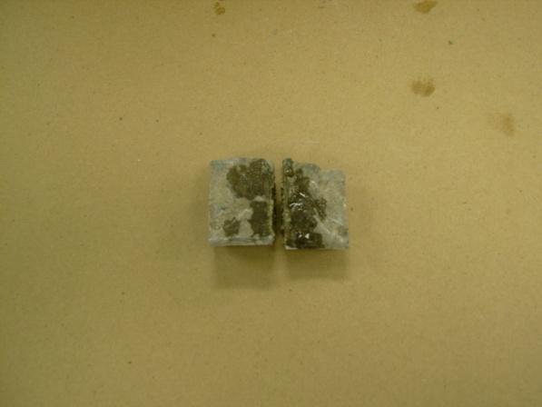


53 Figure 4-8 Penetration Tests of Core Samples 44


54 Figure 4-9 Tensile Testing of Sealants The results were shared with the manufacturers whose main complaint was the width of the cracks was not equal for all and from their comments it was decided to perform a secondary lab test on the crack sealer products, as shown in figure 4-9, with the following results shown in Table
55 Manufacturer s Data Product Tensile Strength (MPa) Viscosity (cps) Table 4-7 Tensile Testing of Deck Sealers Elongation (%) Lab Test Data (7/29/10) Tensile Strength (MPa) Elongation (%) Lab Test Data (12/8/10) Tensile Strength (MPa) Elongation (%) 1-A B C N/A 4-D E No test No test As can be seen the results of the second test is very close to the initial test but still far away from the manufacturers data. With the manufacturers input we devised a plan to build nine scaled down slabs for further testing of the sealers. The slabs were poured using the recommended Type II Portland Cement with a designed compressive strength (f c ) of 5000 psi and a final compressive strength of 7966 psi. The slabs measured 18 inches wide by 4 feet long and 5.5 inches thick as shown in figure 4-10, Lab testing was conducted, on slab model construction having blade placement to create ideal cracks of 0.01 to 0.02 inch of width and a spacing of 4 inches from center. The main complaint from manufacturers was that the crack width in the bridge decks was not equal in the field test. Therefore we created a set of blades (figure 4-12) with two different widths and lengths to plunge into the concrete, while still in the plastic stage, and remove before final set. That resulted in inducing 2 different crack widths (0.01, 0.02 ) and 2 different crack lengths (9, 18 ). (All previous testing performed by researchers dealt with cracks created by stressing concrete or by load application but 46


56 that would not have created equal cracks for all the slabs as requested by manufacturers). Figure 4-10 Sketch of Slab for Construction Figure 4-11 Construction of Test Slabs and Placement of Blades for Crack Width 47


57 Figure 4-12 Blades Constructed for Ideal Cracks Figure 4-13 Testing of Control Slab Specimen and Crack Development The final set time of the concrete was calculated using Schindler s research on Prediction of Concrete Setting so that we could remove the blades without the concrete closing the crack created, we also used a one inch piece of blade to be applied at slab corner to check the theoretical time obtained from the equations. From previous research and observation on the tested bridge, we tested a control slab (with no cracks) to a load of 7200 lb. That load caused 3 cracks spaced at 48
58 approximately 4 inches beginning at the center line of the slab as shown in Figure 4-13, this confirmed the placement of the blades on the slabs with induced cracks as being correctly placed, with the load test results shown in Figure 4-14, maximum deflection occurred at 7000 lbf and was in with the first crack occuring at 2250 lbf the second at 4000 lbf and the third at 6250 lbf Control Slab Load (lb) Load vs Deflection Deflection (in) Figure 4-14 Control Slab Load Test Results The cracks on the rest of the slabs were sealed with the appropriate sealer, as shown in Figure 4-15 and allowed to cure for several weeks. During that time we devised a way to test the slabs upside down (cracks facing up) so as to simulate the cracking on a continuous bridge where the cracks appear on the top surface of the opposite span from where the load is applied. Another reason was to observe the crack behavior under the load during the test. To accomplish both of these goals we built a spreader bar and two different point load bars with the single point load shown in figure


59 Figure 4-15 Sealed Slabs with LDVT's and Dial Gage Figure 4-16 Spreader Bar and Single Point Load Bar The slabs were then subjected to the single point load to observe the behavior of the sealer under load. The results of the load testing of the slabs are shown in Figures 4-17 and
60 Slab 1-A Test 1 (induced cracks single point load) Load (lb) Deflection (in) Load vs Deflection Figure 4-17 Slab 1-A Single Point Load Test Maximum deflection at 7000 lbf was inches. Slab 1-A Test 1 SPDR8(induced cracks single point load) Crack Width (in) Time (sec) CH-0 CH-1 Figure 4-18 Slab 1-A Single Point Load Crack Width Maximum crack width for channel 0 was inches and for channel 1 was inches. Slab 1-A was tested with a single line load. Channel Zero (0) is the induced center crack (0.01 in) and channel 1 is right side induced crack (0.02 in). Center crack initial cracking occurred at 5000 lbs but other cracks did not appear. From the 51

 10000 Load (lb) 5000 0 0.0000 0.0100 0.0200 0.")
61 moment diagram of a single point load the maximum stress occurs at the center with variable stress to the sides. Therefore, a second test with two point loads was performed, this makes the moment diagram take the shape of a flat top pyramid, whereas the outside crack propagated but no visible sealant debonding as shown in Figure 4-19 which also shows the two point load bar constructed for the test. The test results are shown in Figures 4-20 and Figure 4-19 Slab 1-A Crack Propagation and Double Point Load Plate Slab 1-A Test 2 (induced cracks double point load) Load (lb) Deflection (in) Load vs Deflection Figure 4-20 Slab 1-A Test 2 (Double Point Load) 52
62 Crack Width (in) Slab 1-A Test 2 SPDR 8 (induced cracks double point load) Time (sec) CH-0 CH-1 Figure 4-21 Slab 1-A Crack Width (Double Point Load) Test 2 for Slab 1-A yielded a maximum deflection at 7000 lbf of inches with a maximum crack width of in at channel 0 and in at channel 1. The remainder of the slabs where tested in the same manner as the the previous slabs making sure not to test past the yielding of the steel as the best performing sealers would be re-tested on their corresponding slabs to check for the resealing bond strength. Below are the corresponding charts for each of the tested slabs with the results of the testing. Slab 1-B Test 1 (induced cracks single point load) Slab1-B Test2 (induced cracks double point load) Load (lb) Deflection (in) Load (lb) 5000 Load vs Deflection Deflection (in) Load vs Deflection Figure 4-22 Slab 1-B Test Results 53
63 Maximum deflection at 7000 lbf was in for test 1 and in for test 2. Slab 1-B Test 1 SPDR8 (induced cracks single point load) Slab 1-B Test 2 SPDR8 (induced cracks double point load) Crack width (in) Time (sec) CH-0 CH-1 Crack Width (in) Time (sec) CH-0 CH-1 Figure 4-23 Slab 1-B Crack Width Test Results Maximum crack width for test 1 was in for CH-0 and for CH-1. Maximum crack width for test 2 was in for CH-0 and in for CH-1. Slab 2-A Test 1 (induced cracks single point load) Slab 2-A Test 2 (induced cracks double point load) Load (lb) Load vs Deflection Load (lb) Load vs Deflection Deflection (in) Deflection (in) Figure 4-24 Slab 2-A Load Test Results Maximum deflection at 7000 lbf for test 1 was in and in for test 2. 54
64 Crack width (in) Slab 2-A Test 1 SPDR8 (induced cracks single point load) Time (sec) CH-0 CH-1 Crack Width (in) Slab 2-A Test 2 SPDR8 (induced cracks double point load) Time (sec) CH-0 CH-1 Figure 4-25 Slab 2-A Crack Width Test Results Maximum crack width for test 1 was in for CH-0 and in for CH-1, for test 2 the maximum crack width was in for CH-0 and in for CH-1. Slab 2-B Test 1 (induced cracks single point load) Slab 2-B Test 2 (induced cracks double point load) Load (lb) Load vs Deflection Load (lb) Load vs Deflection Deflection (in) Deflection (in) Figure 4-26 Slab 2-B Load Test Results Maximum deflection at 7000 lbf was in for test 1 and in for test 2. 55
65 Crack Width (in) Slab 2-B Test 1 SPDR8 (induced cracks single point load) Time (sec) Crack Width (in) CH CH-1 0 Slab 2-B Test 2 SPDR8 (induced cracks double point load) Time (sec) CH-0 CH-1 Figure 4-27 Slab 2-B Crack Width Test Results Maximum crack width for test 1 was in for CH-0 and in for CH-1 for test 2 the maximum crack width was in for CH-0 and for CH-1. Load (lb) Slab 3-A Test 1 (induced cracks single point load) Deflection (in) Load vs Deflection Load (lb) Slab 3-A Test 2 (induced cracks double point load) Deflection (in) Load vs Deflection Figure 4-28 Slab 3-A Load Test Results The maximum deflection at 7000 lbf was in for test 1 and in for test 2. 56
66 Slab 3-A Test 1 SPDR8 (induced cracks single point load) Slab 3-A Test 2 SPDR8 (induced cracks double point load) Crack Width (in) CH-0 Crack Width (in) CH CH-0 CH-1 Time (sec) Time (sec) Figure 4-29 Slab 3-A Crack Width Test Results Maximum crack width for test 1 was in for CH-0 and in for CH-1, for test 2 the maximum crack width was in for CH-0 and in for CH-1. Slab 3-B Test 1 (induced cracks single point load) Slab 3-B Test2 (induced cracks double point load) Load (lb) Load vs Deflection Load (lb) Load vs Deflection Deflection (in) Deflection (in) Figure 4-30 Slab 3-B Load Test Results Maximum deflection at 7000 lbf was in for test 1 and in for test 2. 57
67 Slab 3-B Test 1 SPDR8 (induced cracks single point load) Slab 3-B Test 2 SPDR8 (induced cracks double point load) Crack Width (in) CH-0 CH-1 Crack Width (in) CH-0 CH-1 Time (sec) Time (sec) Figure 4-31 Slab 3-B Crack Width Test Results Maximum crack width for test 1 was in for CH-0 and for CH-1, for test 2 the maximum crack width was in for CH-0 and in for CH-1. Slab 4-A Test1 (induced cracks single point load) Slab 4-A Test 2 (induced cracks double point load) Load (lb) Load vs Deflection Load (lb) Load vs Deflection Deflection (in) Deflection (in) Figure 4-32 Slab 4-A Load Test Results Maximum deflection at 7000 lbf was in for test 1 and in for test 2. 58
68 Slab 4-A Test 1 SPDR8 (induced cracks single point load) Slab 4-A Test 2 SPDR8 (induced cracks double point load) Crack Width (in) CH-0 Crack Width (in) CH CH-0 CH-1 Time (sec) Time (sec) Figure 4-33 Slab 4-A Crack Width Test Results Maximum crack width for test 1 was in for CH-0 and in for CH-1, for test 2 the maximum crack width was in for CH-0 and in for CH-1. Slab 4-B Test1 (induced cracks single point load) Slab 4-B Test2 (induced cracks double point load) Load (lb) Load vs Deflection Load (lb) Load vs Deflection Deflection (in) Deflection (in) Figure 4-34 Slab 4-B Load Test Results Maximum deflection at 7000 lbf was in for test 1 and in for test 2. 59
69 Crack Width (in) Slab 4-B Test1 SPDR8 (induced cracks single point load) Time (sec) Crack Width (in) CH CH-1 0 Slab 4-B Test 2 SPDR8 (induced cracks double point load) Time (sec) CH-0 CH-1 Figure 4-35 Slab 4-B Crack Width Test Results Maximum crack width for test 1 was in for CH-0 and in for CH-1, for test 2 the maximum crack width was in for CH-0 and in for CH-1. The load test results and the crack/bond condition results are shown in appendix C. In Table 4-8 below are the results of the bond strength of the sealers for each of the induced cracks. 60
70 Table 4-8 Slab Test Table SAMPLE Slab # Load to Crack Full cracks (Lbf) Load to crack Half L Crack (Lbf) 0.01 in 0.02 in 0.01 in 1-A B A B A B A B From the results, the top three sealers were re-applied to their proper slabs with the top performing sealer being applied to the control slab to simulate actual deck cracking 61
71 repair as the control slab had its cracks created by the load test and not induced by the blades, below are the charts for the top three sealers. Load (lb) Control Slab Retest-1 SATEC (after load cracks) Load vs Deflection Load (lb) Control Slab Load vs Deflection Deflection (in) Deflection (in) Figure 4-36 Control Slab Retest Result Comparison The retest chart shows the result of the control slab (no cracks induced) with the threepart HMWM sealer applied after load testing with the chart on the right being the original test of the control slab with no sealer applied. Load (lb) Slab 2-A Retest SATEC (resealed after testing) Deflection (in) Load vs Deflection Load (lb) Slab 2-A Test Deflection (in) Load vs Deflection Figure 4-37 Slab 2-A Retest Result Comparison 62
72 This is the second best performing sealer an MMA re-applied to slab 2-A, with the reapplication of the sealer on the left chart and the original application on the right chart. Slab 4-A Retest SATEC Slab 4-A Test Load (lb) Load vs Deflection Load (lb) Load vs Deflection Deflection (in) Deflection (in) Figure 4-38 Slab 4-A Retest Result Comparison This is the third best performing sealer an epoxy with the reapplication results in the left chart and the original application on the right chart. Below are the charts of the second set of slabs cast for the purpose of verifying the finite element analysis that was performed. 63
73 Control Slab 1 Nov 11 Load (lb) Deflection (in) Load vs Deflection Figure 4-39 Control Slab 1 Load vs Deflection Results Control Induced Crack 1 Nov 11 Load (lb) Deflection (in) Load vs Deflection Figure 4-40 CIC 1 Slab Load vs Deflection Results 64
74 Control Slab 2 Load vs. Deflection Load (lb) Deflection (in) Load vs. Deflection Figure 4-41 Control Slab 2 Load vs Deflection Results Control Induced Crk2 SATEC Load (lb) Deflection (in) Load vs Position Figure 4-42 CIC 2 Slab Load vs Deflection Results 65

 ANSYS model (b) Mesh Figure 4-44 Finite")
75 A Finite Element study was also performed on the slab models as verification to the findings from the lab testing, as shown in Figures 4-43 and Table 4-9 and figure 4-45 show the model results. Figure 4-43 Slab Details (a) ANSYS model (b) Mesh Figure 4-44 Finite Element Model of Slab 66


76 Table 4-9 Model Test Results (a) (b) 67

77 Figure 4-45 FE Model Results (c) Cracking is shown with a circle outline in the plane of the crack, and crushing is shown with an octahedron outline. If the crack has opened and then closed, the circle outline will have an X through it. Each integration point can crack in up to three different planes. The first crack at an integration point is shown with a red circle outline, the second crack with a green outline, and the third crack with a blue outline. 68
Investigation of Likelihood of Cracking in Reinforced Concrete Bridge Decks
 International Journal of Concrete Structures and Materials Vol.7, No.1, pp.79 93, March 2013 DOI 10.1007/s40069-013-0034-3 ISSN 1976-0485 / eissn 2234-1315 Investigation of Likelihood of Cracking in Reinforced
Basic types of bridge decks
 Bridge Deck Slab 1 Introduction 2 Bridge deck provide the riding surface for traffic, support & transfer live loads to the main load carrying member such as girder on a bridge superstructure. Selection
Bridge Deck Preservation Treatment Options
 Western Bridge Preservation Partnership May 17-18, 2016 Salt Lake City, Utah Bridge Deck Preservation Treatment Options Gregg Freeman - Kwikbond Polymers Rob Johnson - Transpo Industries Clay Christiansen
Sealing Concrete Bridge Decks: Overview of Current Technologies. Lorella Angelini Angelini Consulting Services
 Sealing Concrete Bridge Decks: Overview of Current Technologies Lorella Angelini Angelini Consulting Services Concrete Non-Film Forming Sealers Overview of most recent and commonly used non-film forming
IDOT Bridge Decks: Ongoing IDOT Research & An FHWA Process Review
 IDOT Bridge Decks: Ongoing IDOT Research & An FHWA Process Review James Krstulovich, P.E. Concrete Research Engineer Bureau of Materials & Physical Research Bridge Deck Cracking in Illinois Transverse
CONCRETE WORK CONCRETE WORK. Underground Electric Distribution Standards I. SCOPE APPLICABLE STANDARDS
 Underground Electric Distribution Standards I. SCOPE This section includes the standards for concrete, reinforcing steel, formwork, concrete placement, curing, and construction joints. Concrete work for
Sustainable Polymer Concrete Materials for Bridge and Concrete Rehabilitation, Maintenance, and Preservation
 Sustainable Polymer Concrete Materials for Bridge and Concrete Rehabilitation, Maintenance, and Preservation Arthur M. Dinitz Transpo Industries Inc, CEO and Chairman, 20 Jones St., New Rochelle, New York
AASHTO/NTPEP Rapid Set Concrete Patching Materials
 AASHTO/NTPEP Rapid Set Concrete Patching Materials User Guide 2015 Introduction: The National Transportation Product Evaluation Program (NTPEP) was established to minimize the amount of duplicative testing
DURABILITY PERFORMANCE OF EPOXY INJECTED REINFORCED CONCRETE BEAMS WITH AND WITHOUT FRP FABRICS
 DURABILITY PERFORMANCE OF EPOXY INJECTED REINFORCED CONCRETE BEAMS WITH AND WITHOUT FRP FABRICS Prof. John J. Myers Associate Professor CIES / Department of Civil, Arch., & Env. Engineering University
EGCE 406: Bridge Design
 EGCE 406: Bridge Design Design of Slab for Praveen Chompreda Mahidol University First Semester, 2006 Bridge Superstructure Outline Components of bridge Superstructure Types Materials Design of RC Deck
Characterization of Physical Properties of Roadware Clear Repair Product
 Characterization of Physical Properties of Roadware Clear Repair Product November 5, 2009 Prof. David A. Lange University of Illinois at Urbana-Champaign Introduction Roadware MatchCrete Clear (MCC) is
SUBMITTED TO: PRODUCT INFORMATION: SUBMITTED BY: FOR ARCHITECT/ENGINEER USE:
 SUBMITTED TO: TO: SUBMITTAL DATE: COMPANY NAME: PROJECT: PRODUCT INFORMATION: SUBMITTED PRODUCT: CRACKBOND HEALER/SEALER SPECIFIED PRODUCT: SECTION: PAGE: PARAGRAPH: DETAIL/SHEET NO.: DESCRIPTION OF APPLICATION:
SPECIAL SPECIFICATION 4429 Multiple-Layer Polymer Concrete Overlay
 2004 Specifications SPECIAL SPECIFICATION 4429 Multiple-Layer Polymer Concrete Overlay 1. Description. Furnish and place a multi-layer polymer overlay consisting of a crack seal, polymer resin and aggregates.
Nelson Testing Laboratories
 in Elmhurst, Illinois, USA has demonstrated proficiency for the testing of construction materials and has conformed to the requirements established in AASHTO R 18 and the AASHTO Accreditation policies
THIN BONDED OVERLAY AND SURFACE LAMINATES
 August 2001 FINAL REPORT THIN BONDED OVERLAY AND SURFACE LAMINATES Federal Highway Administration Demonstration Projects Program ISTEA Section 6005 Bridge Deck Overlays Constructed by The Ohio Department
Accelerated Bridge Strengthening using UHP(FR)C
C") ABC-UTC at Florida International University (FIU) Webinar : Thursday, December 14, 2017 Accelerated Bridge Strengthening using UHP(FR)C Eugen Brühwiler EPFL Swiss Federal Institute of Technology Lausanne,
ABC-UTC at Florida International University (FIU) Webinar : Thursday, December 14, 2017 Accelerated Bridge Strengthening using UHP(FR)C Eugen Brühwiler EPFL Swiss Federal Institute of Technology Lausanne,
Investigation of Negative Moment Reinforcing in Bridge Decks
 Tech Transfer Summaries Institute for Transportation 9-2015 Investigation of Negative Moment Reinforcing in Bridge Decks Brent Phares Institute for Transportation, bphares@iastate.edu Sameera Jayathilaka
OKLAHOMA DEPARTMENT OF TRANSPORTATION SPECIAL PROVISIONS FOR CONCRETE SURFACE REPAIR BY SEALING
 523-1(a-f) 99 OKLAHOMA DEPARTMENT OF TRANSPORTATION SPECIAL PROVISIONS FOR CONCRETE SURFACE REPAIR BY SEALING These Special Provisions revise, amend, and where in conflict, supersede applicable sections
Wiss, Janney, Elstner Associates, Inc.
 in Northbrook, Illinois, USA has demonstrated proficiency for the testing of construction materials and has conformed to the requirements established in AASHTO R 18 and the AASHTO Accreditation policies
DEVELOPMENT OF A SPECIFICATION FOR LOW CRACKING BRIDGE DECK CONCRETE IN VIRGINIA
 DEVELOPMENT OF A SPECIFICATION FOR LOW CRACKING BRIDGE DECK CONCRETE IN VIRGINIA Virginia DOT Workshop Charlottesville, VA Harikrishnan Nair, Ph.D., P.E, VTRC Senior Research Scientist October 4, 2017
Class Topics & Objectives
 EGCE 406: Bridge Design Design of Slab for Bridge Deck Praveen Chompreda, Ph.D. Mahidol University First Semester, 2010 Class Topics & Objectives Topics Objective Bridge Superstructures Students can identify
Polymer Materials for Bridge Deck Rehabilitation and Preservation
 Polymer Materials for Bridge Deck Rehabilitation and Preservation Bridge Deck Overlay Questionnaire Does your state use thin polymer deck overlays? Maryland: -- Delaware: New Jersey: Yes Pennsylvania:
Dusit Roongsang, P.E. Presented at. PNWS AWWA Conference Bellevue, WA May 1, 2015
 Dusit Roongsang, P.E. Presented at PNWS AWWA Conference Bellevue, WA May 1, 2015 Not waterproof structures Leakage rate is suitable for intended use Contain water Prevent contamination of contents Prevent
NTPEP Evaluation of Spray Applied Non-Structural and Structural Pipe Liners for Storm Water Conveyance
 Work Plan for NTPEP Evaluation of Spray Applied Non-Structural and Structural Pipe Liners for Storm Water Conveyance AASHTO Designation: [SAL] (2018) American Association of State Highway and Transportation
Quantification of Cracks in Concrete Bridge Decks in Ohio District 3
 Quantification of Cracks in Concrete Bridge Decks in Ohio District 3 Student Study Project State Job Number: 134564 Research Results Presentation 06-06-2012 ODOT Central Office, Columbus, OH Email questions
SECTION RIGID PAVEMENT. 1. Portland Cement Concrete (PCC) pavement. 2. Section Aggregate Base Course.
 pavement. 2. Section Aggregate Base Course.") SECTION 02750 RIGID PAVEMENT PART 1 GENERAL 1.1 SUMMARY A. Section Includes: 1. Portland Cement Concrete (PCC) pavement. B. Related Sections: 1.2 REFERENCES 1. Section 02315 Excavation. 2. Section 02721
SECTION 02750 RIGID PAVEMENT PART 1 GENERAL 1.1 SUMMARY A. Section Includes: 1. Portland Cement Concrete (PCC) pavement. B. Related Sections: 1.2 REFERENCES 1. Section 02315 Excavation. 2. Section 02721
DMS EPOXIES AND ADHESIVES
 DMS - 6100 EFFECTIVE DATES: OCTOBER 2007 MAY 2014. 6100.1. Description. This Specification details requirements for various types of epoxy and adhesive materials suitable for highway use. These materials
Fundamentals of Concrete
 Components Cement Water Fine Aggregate Coarse Aggregate Fundamentals of Range in Proportions Advantages of Reducing Water Content: Increased strength Lower permeability Fundamentals of Increased resistance
ACI MANUAL OF CONCRETE PRACTICE-2009
 ACI MANUAL OF CONCRETE PRACTICE-2009 The ACI Manual of Concrete Practice is a six-part compilation of current ACI standards and committee reports. -ACI117-06 to ACI224.3R-95(08) Part 2-ACI 225-99(05) to
Repairs to the Primary Tanks at a Wastewater Treatment Plant
 Repairs to the Primary Tanks at a Wastewater Treatment Plant Edited by Kelly M. Page As part of the City of Grand Rapids, Michigan, Capital Improvement Plan, the city required an assessment of the condition
Critical Structures Construction Issues
 Critical Structures Construction Issues FLORIDA DEPARTMENT OF TRANSPORTATION STATE CONSTRUCTION OFFICE Specification 1-3: Definitions Contractor s Engineer of Record Specialty Engineer CLASS OF CONTRACTOR
INVESTIGATION OF CURING PERIOD OF CEMENTITIOUS ADHESIVE AND PERFORMANCE OF RUST PREVENTION
 Geotec., Const. Mat. & Env., DOI: https://doi.org/10.21660/2018.43.3717 ISSN: 2186-2982 (Print), 2186-2990 (Online), Japan INVESTIGATION OF CURING PERIOD OF CEMENTITIOUS ADHESIVE AND PERFORMANCE OF RUST
PERFORMANCE-RELATED SPECIAL PROVISION FOR HIGH PERFORMANCE CONCRETE MIX DESIGNS FOR CONCRETE SUPERSTRUCTURE (Tollway)
") PERFORMANCE-RELATED SPECIAL PROVISION FOR HIGH PERFORMANCE CONCRETE MIX DESIGNS FOR CONCRETE SUPERSTRUCTURE (Tollway) Effective: October 12, 2012 Revised: June 14, 2013 DESCRIPTION This work consists of
PERFORMANCE-RELATED SPECIAL PROVISION FOR HIGH PERFORMANCE CONCRETE MIX DESIGNS FOR CONCRETE SUPERSTRUCTURE (Tollway) Effective: October 12, 2012 Revised: June 14, 2013 DESCRIPTION This work consists of
DIVISION 2500 MISCELLANEOUS METHODS OF TEST
 TABLE OF CONTENTS DIVISION 2500 MISCELLANEOUS METHODS OF TEST SECTION 2501 PART V... 2500-1 PAGE i SECTION 2501 PART V 2501.1 GENERAL In order to properly monitor materials on a project, follow all applicable
Would You Like Concrete With Little or No Shrinkage, Cracking, and Curling??? We Will Focus on:
 Would You Like Concrete With Little or No Shrinkage, Cracking, and Curling??? We Will Focus on: Coarse Aggregates Admixtures Including Shrinkage Reducing and Shrinkage Compensating Admixtures Evaporation
ATLANTIC TESTING LABORATORIES Hot Weather Concreting
 ATLANTIC TESTING LABORATORIES Hot Weather Concreting ACI 305R ACI 305.1 CNY Engineering Expo November 11, 2013 Topics of Discussion 5 Essentials of Quality Concrete Hot Weather Defined by ACI Potential
5 Concrete Placement
 5 Concrete Placement Testing Entrained Air Slump Strength Water/Cementitious Ratio Mixing Placing Concrete Compressive Test Specimens Curing De-Tensioning Multiple Strand Release Single Strand Release
Reed, Hale 1. Slag Cement Concrete for Use in Bridge Decks. August 1, Words (6 Tables = 1500 words)
") Reed, Hale 1 1 2 3 4 5 6 7 8 9 10 11 12 13 14 15 16 17 18 19 20 21 22 23 24 25 26 27 28 29 30 31 32 33 34 35 36 37 38 39 40 41 42 43 44 45 46 Slag Cement Concrete for Use in Bridge Decks August 1, 2011
Reed, Hale 1 1 2 3 4 5 6 7 8 9 10 11 12 13 14 15 16 17 18 19 20 21 22 23 24 25 26 27 28 29 30 31 32 33 34 35 36 37 38 39 40 41 42 43 44 45 46 Slag Cement Concrete for Use in Bridge Decks August 1, 2011
SHEAR STRENGTHENING OF RC BRIDGE PIERS BY STEEL JACKETING WITH EXPANSIVE CEMENT MORTAR AS ADHESIVE
 - Technical Paper - SHEAR STRENGTHENING OF RC BRIDGE PIERS BY STEEL JACKETING WITH EXPANSIVE CEMENT MORTAR AS ADHESIVE Aloke RAJBHANDARY *1, Govinda R. PANDEY *2, Hiroshi MUTSUYOSHI *3 and Takeshi MAKI
Properties of Concrete. Properties of Concrete. Properties of Concrete. Properties of Concrete. Properties of Concrete. Properties of Concrete
 CIVL 1112 Contrete Introduction from CIVL 1101 1/10 Concrete is an artificial conglomerate stone made essentially of Portland cement, water, and aggregates. While cement in one form or another has been
Ultimate strength prediction for reinforced concrete slabs externally strengthened by fiber reinforced polymer (FRP)
") Ultimate strength prediction for reinforced concrete slabs externally strengthened by fiber reinforced polymer (FRP) Abstract This paper presents the potential use of externally bonded fiber reinforced
Ultimate strength prediction for reinforced concrete slabs externally strengthened by fiber reinforced polymer (FRP) Abstract This paper presents the potential use of externally bonded fiber reinforced
SPECIAL SPECIFICATION 4703 Repair Of Impact Damaged Prestressed Concrete Bridge Beams
 1993 Specifications CSJ 0162-01-080, etc. SPECIAL SPECIFICATION 4703 Repair Of Impact Damaged Prestressed Concrete Bridge Beams 1. Description. This Item shall govern for the repair of impact damaged prestressed
Internal Curing. Improving Concrete Durability and Sustainability Using Internal Curing. Using Prewetted Lightweight Aggregates
 Internal Curing Using Prewetted Lightweight Aggregates Improving Concrete Durability and Sustainability Using Internal Curing Presented to: LA DOTD Transportation Conference February, 2013 Jeff Speck,
MICHIGAN DEPARTMENT OF TRANSPORTATION SPECIAL PROVISION FOR HIGH FRICTION SURFACE TREATMENT. OFS:CER 1 of 5 APPR:GM:TEH: FHWA:APPR:
 MICHIGAN DEPARTMENT OF TRANSPORTATION SPECIAL PROVISION FOR HIGH FRICTION SURFACE TREATMENT OFS:CER 1 of 5 APPR:GM:TEH:04-04-13 FHWA:APPR: 04-21-14 a. Description. This work consists of providing all labor,
EVALUATION OF TIME-DEPENDENT BEHAVIOUR OF COMPOSITE CONCRETE SLABS WITH STEEL DECKING (AN EXPERIMENTAL STUDY)
") VIII International Conference on Fracture Mechanics of Concrete and Concrete Structures FraMCoS-8 J.G.M. Van Mier, G. Ruiz, C. Andrade, R.C. Yu and X.X. Zhang (Eds) EVALUATION OF TIME-DEPENDENT BEHAVIOUR
VIII International Conference on Fracture Mechanics of Concrete and Concrete Structures FraMCoS-8 J.G.M. Van Mier, G. Ruiz, C. Andrade, R.C. Yu and X.X. Zhang (Eds) EVALUATION OF TIME-DEPENDENT BEHAVIOUR
Early Thermal Cracking of Concrete
 THE HIGHWAYS AGENCY THE SCOTTISH OFFICE DEVELOPMENT DEPARTMENT Incorporating Amendment No.1, 1989 THE WELSH OFFICE Y SWYDDFA GYMREIG THE DEPARTMENT OF THE ENVIRONMENT FOR NORTHERN IRELAND Early Thermal
SECTION US Patent 8,857,130 B1 CAST-IN-PLACE CONCRETE WITH ARDEX CONCRETE MANAGEMENT SYSTEMS (ACMS ) EARLY MC APPLICATION
 EARLY MC APPLICATION") ARDEX GUIDE SPECIFICATION ARDEX CONCRETE MANAGEMENT SYSTEMS (ACMS ) Cast-In-Place Concrete to Receive the ARDEX Concrete Management Systems including ARDEX Self-Leveling Underlayments SECTION 03 30 00
ARDEX GUIDE SPECIFICATION ARDEX CONCRETE MANAGEMENT SYSTEMS (ACMS ) Cast-In-Place Concrete to Receive the ARDEX Concrete Management Systems including ARDEX Self-Leveling Underlayments SECTION 03 30 00
Hot Weather Concreting
 Hot Weather Concreting Presented by: Tom Pelo Area Sales Leader BASF Construction Chemicals Admixture Division ACI 305 Definition of Hot Weather Any combination of high ambient temperature, high concrete
SECTION 434 HIGH PERFORMANCE CONCRETE (HPC)
") SECTION 434 HIGH PERFORMANCE CONCRETE (HPC) 434.01 DESCRIPTION. This work shall consist of the construction of portland cement concrete deck slabs, headblocks, bridge sidewalks, unsurfaced bridge approach
SECTION 434 HIGH PERFORMANCE CONCRETE (HPC) 434.01 DESCRIPTION. This work shall consist of the construction of portland cement concrete deck slabs, headblocks, bridge sidewalks, unsurfaced bridge approach
The Pennsylvania State University. The Graduate School. Department of Civil Engineering TIME-DEPENDENT ANALYSIS OF PRETENSIONED
 The Pennsylvania State University The Graduate School Department of Civil Engineering TIME-DEPENDENT ANALYSIS OF PRETENSIONED CONCRETE BRIDGE GIRDERS A Dissertation in Civil Engineering by Brian D. Swartz
The use of 0.5 and 0.6 in. (13 and 15 mm) diameter
 diameter") Benefits of using.7 in. (18 mm) diameter strands in precast, pretensioned girders: A parametric investigation Jessica Salazar, Hossein Yousefpour, Alex Katz, Roya Alirezaei Abyaneh, Hyun su Kim, David
Benefits of using.7 in. (18 mm) diameter strands in precast, pretensioned girders: A parametric investigation Jessica Salazar, Hossein Yousefpour, Alex Katz, Roya Alirezaei Abyaneh, Hyun su Kim, David
FINAL REPORT EVALUATION OF HYDRAULIC CEMENT CONCRETE OVERLAYS PLACED ON THREE PAVEMENTS IN VIRGINIA. Michael M. Sprinkel, P.E.
 FINAL REPORT EVALUATION OF HYDRAULIC CEMENT CONCRETE OVERLAYS PLACED ON THREE PAVEMENTS IN VIRGINIA Michael M. Sprinkel, P.E. Research Manager Celik Ozyildirim, Ph.D. Principal Research Scientist (The
NTPEP Evaluation of Spray Applied Non-Structural and Structural Pipe Liners for Storm Water Conveyance
 Work Plan for NTPEP Evaluation of Spray Applied Non-Structural and Structural Pipe Liners for Storm Water Conveyance AASHTO Designation: [SAL] (2016) American Association of State Highway and Transportation
Effect of Alkali Silica Reaction Expansion and Cracking on Structural Behavior of Reinforced Concrete Beams
 ACI STRUCTURAL JOURNAL Title no. 95-S44 TECHNICAL PAPER Effect of Alkali Silica Reaction Expansion and Cracking on Structural Behavior of Reinforced Concrete Beams by Shenfu Fan and John M. Hanson A laboratory
1. CORROSION OF REINFORCEMENT
 MAB 1033 Structural Assessment and Repair 1. CORROSION OF REINFORCEMENT Professor Dr. Mohammad bin Ismail C09-313 Learning Outcome At the end of the course students should be able to understand Mechanism
Flood Testing Laboratories, Inc.
 in Chicago, Illinois, USA has demonstrated proficiency for the testing of construction materials and has conformed to the requirements established in AASHTO R 18 and the AASHTO Accreditation policies established
TECHNICAL SPECIAL PROVISION FOR CONCRETE REPAIRS. Financial Project ID , &
 TECHNICAL SPECIAL PROVISION FOR CONCRETE REPAIRS Financial Project ID 429140-1-52-01, 429140-2-52-01 & 428267-1-52-01 The official record of this Technical Special Provision is the electronic file signed
10/11/2017. Identify Processes or Materials Causing Distress or Failure. Portland Cement Association. References
 // Concrete Surface Defects: Causes, Prevention, and Cure. Presented to: Wednesday, October, Presented by: Michelle L. Wilson Director, Concrete Technology Portland Cement Association www.cement.org Identify
KANSAS DEPARTMENT OF TRANSPORTATION SPECIAL PROVISION TO THE STANDARD SPECIFICATIONS, EDITION 2007
 Sheet 1 of 6 KANSAS DEPARTMENT OF TRANSPORTATION SPECIAL PROVISION TO THE STANDARD SPECIFICATIONS, EDITION 2007 Delete SECTION 2501 and replace with the following: SECTION 2501 PART V 2501.1 GENERAL In
Experimental investigation of the use of CFRP grid for shear strengthening of RC beams
 Journal of Asian Concrete Federation Vol. 2, No. 2, Dec. 2016, pp. 117-127 ISSN 2465-7964 / eissn 2465-7972 http://dx.doi.org/10.18702/acf.2016.12.2.2.117 Experimental investigation of the use of CFRP
Final Report 6/19/2013. Sponsored by:
 Final Report 6/19/2013 Sponsored by: What is the problem? Widespread premature cracking of concrete bridge parapets Many vertical cracks (between joints) Some horizontal cracks (at level of top bars) A
CONCRETE MATERIALS PROPERTIES AND TESTING
 CONCRETE MATERIALS PROPERTIES AND TESTING 1 Concrete ingredients Cement Fine aggregate Coarse aggregate Water Admixtures 2 3 4 Properties of cement Physical properties of cement Fineness Standard consistency
Pennoni Associates, Inc.
 in Bethlehem, Pennsylvania, USA has demonstrated proficiency for the testing of construction materials and has conformed to the requirements established in AASHTO R 18 and the AASHTO Accreditation policies
Research on Weight Reduction of PC Composite Members Using Ultra High Strength Fiber Reinforced Cementitious Composites (UFC)
") Research on Weight Reduction of PC Composite Members Using Ultra High Strength Fiber Reinforced Cementitious Composites (UFC) H. Murata 1), J. Niwa 2), and C. Sivaleepunth 3) 1) Master course 2nd year
Research on Weight Reduction of PC Composite Members Using Ultra High Strength Fiber Reinforced Cementitious Composites (UFC) H. Murata 1), J. Niwa 2), and C. Sivaleepunth 3) 1) Master course 2nd year
JCI Guidelines Chapters 1 and 2
 JCI Guidelines Chapters 1 and 2 Takafumi Noguchi The University of Tokyo 1 Chapter 1 General 1.1 Scope 1.2 Definitions 1.3 Notation 2 1.1 Scope This document provides standard guidelines for design, construction
SHEAR STRENGTH OF ASR-DETERIORATED RC MEMBERS AND SHEAR REINFORCING EFFECT OF REPAIR BY ADDING REBAR
 VIII International Conference on Fracture Mechanics of Concrete and Concrete Structures FraMCoS-8 J.G.M. Van Mier, G. Ruiz, C. Andrade, R.C. Yu and X.X. Zhang (Eds) SHEAR STRENGTH OF ASR-DETERIORATED RC
A. Drawings and general provisions of the contract, including General and Supplementary Conditions, apply to this section.
 Product Specification for: Rapid Set DOT Repair Mix SECTION 03 01 30 MAINTENANCE OF CAST-IN-PLACE CONCRETE SECTION 03 01 40 MAINTENANCE OF PRECAST CONCRETE SECTION 03 01 50 MAINTENANCE OF CAST DECKS AND
Rapport sur les causes techniques de l effondrement du viaduc de la Concorde
 Rapport sur les causes techniques de l effondrement du viaduc de la Concorde Annexe A8 Essais de chargement en laboratoire réalisés à l Université McGill Rédigé par : Denis Mitchell, ing., Ph.D. William
VARIOUS TYPES OF SLABS
 VARIOUS TYPES OF SLABS 1 CHOICE OF TYPE OF SLAB FLOOR The choice of type of slab for a particular floor depends on many factors. Economy of construction is obviously an important consideration, but this
ULTRA-HIGH STRENGTH SHEAR KEY GROUT
 ULTRA-HIGH STRENGTH SHEAR KEY GROUT 187 April 30, 2015 SPECIFICATION FOR ULTRA-HIGH STRENGTH SHEAR KEY GROUT SCOPE This specification consists of the proper material selection and production of Ultra-High-
General Information for Joints
 Design Manual Chapter 5 - Roadway Design 5G - PCC Pavement Joints 5G-1 General Information for Joints A. General Information The need for a jointing system in concrete pavements results from the desire
Application of Ultra High Performance Concrete in Expediting the Replacement and Rehabilitation of Highway Bridges
 Application of Ultra High Performance Concrete in Expediting the Replacement and Rehabilitation of Highway Bridges Abstract M. Ataur Rahman, P.Eng., Ph.D. and Tyler McQuaker, P.Eng. Ministry of Transportation
SPECIAL SPECIFICATION 4897 Repair Structural Concrete
 1993 Specifications CSJ 0331-04-045 SPECIAL SPECIFICATION 4897 Repair Structural Concrete 1. Description. This Item shall govern for the repair of delaminated, spalled and chipped areas of concrete foundations,
INNOVATIVE FIBRE REINFORCED BRIDGE DECK MODULES ABSTRACT
 INNOVATIVE FIBRE REINFORCED BRIDGE DECK MODULES Heather Crocker, ISIS Canada, Winnipeg, MB Emile Shehata, Wardrop Engineering Inc., Winnipeg, MB Rick Haldane-Wilsone, Wardrop Engineering Inc., Winnipeg,
HIGH PERFORMANCE CONCRETE. by John J. Roller CTLGroup
 HIGH PERFORMANCE CONCRETE by John J. Roller CTLGroup Early Louisiana HPC Research Law & Rasoulian (1980) Adelman & Cousins (1990) Bruce, Russell & Roller (1990-1993) Law & Rasoulian (1980) Concrete strengths
BUILDING STRENGTH PARKING GARAGE CONCRETE CONSTRUCTION SOLUTIONS
 BUILDING STRENGTH PARKING GARAGE CONCRETE CONSTRUCTION SOLUTIONS ENDURANCE TRAFFIC DECK SYSTEM BROCHURE Fight Damaging Forces and Gain Longer Life with Dayton Superior s Proven Products and Solutions that
NTPEP Evaluation of Rapid Set Concrete Patching Materials for Portland Cement Concrete
 Standard Practice for NTPEP Evaluation of Rapid Set Concrete Patching Materials for Portland Cement Concrete AASHTO Designation: [RSCP-14] American Association of State Highway and Transportation Officials
CSI SPECIFICATIONS SURFACE-APPLIED CRYSTALLINE WATERPROOFING Section
 SURFACE-APPLIED CRYSTALLINE WATERPROOFING Section 07 16 16 This section includes Krystol T1 crystalline waterproofing, applied to new or existing concrete substrates, above or below grade, on either dry
BORAL MICRON 3 WORKABILITY, SHRINKAGE CRACK RESISTANCE, AND HIGH STRENGTH CONCRETE
 Workability reduces water and high range water reducing (HRWR) admixture demand and improves concrete workability. This is in contrast to most highly reactive pozzolans. Figure 1 is a summary of the water
Pumice Pozz vs. Fly Ash
 Pumice Pozz vs. Fly Ash Extensive ASTM-standard Research Quantifies Pumice as the Ideal Replacement for Fly Ash in Concrete IN EACH AND EVERY ONE of the concrete performance categories that matter, clean,
The Fundamentals for Fiber-Reinforced Polymer (FRP) Strengthening
 Strengthening") The Fundamentals for Fiber-Reinforced Polymer (FRP) Strengthening Extending the life of the world s infrastructure. The Fundamentals for FRP Strengthening United States infrastructure is aging. In its
The Fundamentals for Fiber-Reinforced Polymer (FRP) Strengthening Extending the life of the world s infrastructure. The Fundamentals for FRP Strengthening United States infrastructure is aging. In its
Module 3 Page 1 of 23
 Module 3 Page 1 of 23 Internal Curing Module III: and Volume Change Presented by Jason Weiss, Purdue University, March 19 th, 2013 Module 3: and Slide 1 of 66 To understand how shrinkage relates to stress
Inspection of Concrete Part 2
 Inspection of Concrete Part 2 JOINTING IN SLABS, DRIVES, WALKS HOT WEATHER COLD WEATHER Steve Waalkes, P.E. Dir. of Engineering W. Mich. Jointing Why do we joint? Reinforcement Types of Joints Sawing &
FLEXURAL AND SHEAR STRENGTHENING OF REINFORCED CONCRETE STRUCTURES WITH NEAR SURFACE MOUNTED FRP RODS
 FLEXURAL AND SHEAR STRENGTHENING OF REINFORCED CONCRETE STRUCTURES WITH NEAR SURFACE MOUNTED FRP RODS ABSTRACT The use of Near Surface Mounted (NSM) Fiber Reinforced Polymer (FRP) rods is a new and promising
Bridge Deck Issues. Paul D. Krauss, P. E. Wiss, Janney, Elstner, Associates
 Bridge Deck Issues Paul D. Krauss, P. E. Wiss, Janney, Elstner, Associates 847-753-6517 pkrauss@wje.com Bridge Deck Issues Cracking Corrosion Solutions Material Selection Corrosion Resistant Reinforcing
By CTS Cement Manufacturing Corp.
 CSI SECTION 03 60 00 GROUTING 03 62 00 NON-SHRINK GROUTING 03 62 13 NON-METALLIC NON-SHRINK GROUTING High Flow, Non-Metallic, Multi-Purpose, Cementitious, Non-Shrink Grout EDITOR NOTE: The following guideline
SECTION SURFACE-APPLIED CRYSTALLINE WATERPROOFING AND CONCRETE REPAIR
 SECTION PART 1 GENERAL 1.1 SECTION INCLUDES A. Surface-applied crystalline waterproofing treatment. B. Crystalline compounds for the repair of leaking cracks, holes and joints found in concrete. 1.2 RELATED
10/10/2007. Is it Dark at Night?
 To Crack or Not to Crack? That is the Question Causes and Prevention Presented by: Dave Frentress Does Concrete Crack? Is it Dark at Night? Cracking A recent NRMCA survey identified cracking as the number
DIAGNOSIS AND PREVENTION OF SURFACE IMPERFECTIONS
 DIAGNOSIS AND PREVENTION OF SURFACE IMPERFECTIONS IMPERFECTION a fault, blemish, or undesirable feature. the state of being faulty or incomplete. Claude Goguen, PE, LEED AP National Precast Concrete Association
Patching repair with ECC on cracked concrete surface
 Patching repair with ECC on cracked concrete surface K. Rokugo 1, M. Kunieda 2 and S. C. Lim 3 1 Gifu University, Japan 2 Nagoya University, Japan 3 Deros Co.,Ltd, Japan Abstract Performance requirements
Strength of Non-Prismatic Composite Self-Compacting Concrete Steel Girders
 Strength of Non-Prismatic Composite Self-Compacting Concrete Steel Girders *Haitham H. Muteb 1) and Mustafa S. Shaker 2) 1), 2) Department of Civil Engineering, UoB, Hillah 51002, Iraq 1) haithammuteb@gmail.com
Concrete Deck Cracking Investigation SR309 over Church Road, Montgomery County, PA
 Lehigh University Lehigh Preserve ATLSS Reports Civil and Environmental Engineering 8-1-2009 Concrete Deck Cracking Investigation SR309 over Church Road, Montgomery County, PA Ian C. Hodgson Stephen Pessiki
Prevention of Transverse Bumps Over Crack Sealant During Asphalt Overlay Construction
 Prevention of Transverse Bumps Over Crack Sealant During Asphalt Overlay Construction Crack sealants are often utilized as a pavement preservation tool in asphalt pavements. These sealants are placed in
Prestress Superstructure Tutorial
 AASHTOWare BrDR 6.8.2 Prestress Superstructure Tutorial PS14 Prestressed Concrete I Beam Example PS14 - Prestressed Concrete I Beam Example This example details the data input of a prestressed concrete
CFRP Strengthening of KY 583 Over the Bluegrass Parkway Bridge in Hardin Country
 Transportation Kentucky Transportation Center Research Report University of Kentucky Year 2017 CFRP Strengthening of KY 583 Over the Bluegrass Parkway Bridge in Hardin Country Abheetha Peiris Issam E.
Update on the Condition of Tollway HPC Bridge Decks Built in 2013 & 2014 NCC Spring Meeting April 22, 2015
 Update on the Condition of Tollway HPC Bridge Decks Built in 2013 & 2014 NCC Spring Meeting April 22, 2015 Condition of of Tollway Crack Resistant High Performance Concrete Bridge Decks In 2012, CTL Group
CHAPTER III DYNAMIC BEHAVIOR OF A LABORATORY SPECIMEN
 CHAPTER III DYNAMIC BEHAVIOR OF A LABORATORY SPECIMEN To address the vibration response of a long span deck floor system, an experiment using a specimen that resembles the conditions found in the in-situ
Introduction of a Japan Concrete Institute Guideline: Practical Guideline for Investigation, Repair and Strengthening of Cracked Concrete Structures
 Journal of Civil Engineering and Architecture 9 (2015) 213-224 doi: 10.17265/1934-7359/2015.02.010 D DAVID PUBLISHING Introduction of a Japan Concrete Institute Guideline: Practical Guideline for Investigation,
SECTION CONCRETE REPAIR AND PATCHING
 SECTION 03937 CONCRETE REPAIR AND PATCHING PART 1 - GENERAL 1.1 RELATED DOCUMENTS A. Drawings and general provisions of the Contract, including General Conditions, General Specifications, and Division
Modjeski and Masters, Inc. Consulting Engineers 04/18/06 St. Croix River Bridge 3D Analysis Report Introduction
 Introduction This memo presents a summary of a three dimensional (3D) analysis of the Organic concept for the proposed St. Croix River bridge project. The Organic concept has several attributes that are