CITY OF LOS ANGELES CALIFORNIA
|
|
|
- Abel Blankenship
- 6 years ago
- Views:
Transcription

1

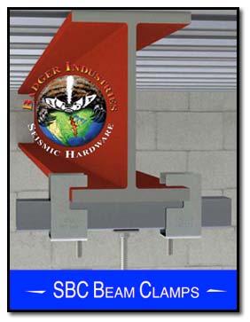
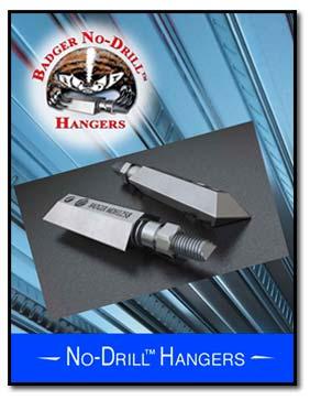
2 BOARD OF BUILDING AND SAFETY COMMISSIONERS VAN AMBATIELOS PRESIDENT E. FELICIA BRANNON VICE PRESIDENT JOSELYN GEAGA-ROSENTHAL GEORGE HOVAGUIMIAN JAVIER NUNEZ CITY OF LOS ANGELES CALIFORNIA ERIC GARCETTI MAYOR DEPARTMENT OF BUILDING AND SAFETY 201 NORTH FIGUEROA STREET LOS ANGELES, CA FRANK M. BUSH GENERAL MANAGER SUPERINTENDENT OF BUILDING OSAMA YOUNAN, P.E. EXECUTIVE OFFICER Jobsite Supply Co. RESEARCH REPORT: RR Mission Gorge Place (CSI # 13080) San Diego, CA Attn: Brad Lawhorn REEVALUATION DUE (714) DATE: May 1, 2018 Issued Date: December 1, 2017 Code: 2017 LABC GENERAL APPROVAL Technical Modification Badger Industries Seismic and Components DETAILS The Badger Industries seismic SSC, SSC-HD and SSC-RF components are composed of ASTM A1011 CS, Grade 33 or equivalent minimum 33,000 psi yield strength carbon steel. Pivot pin is composed of (1/2") diameter ASTM A307 or equivalent carbon steel. A slotted tabbed washer sized to fit connection is provided with, and is required to be installed with each Badger Industries SSC-RF seismic bracket. Seismic brackets can be used for upper or lower brace end connections. Badger SBEMT pivot arm shall be removed when connecting cable brace member to pivot pin. The Allowable and (LRFD) capacities are listed in Attachments 1, 2 and 3. The Badger Industries seismic SB1258 and SBRF components are composed of ASTM A1011 CS, Grade 33 or equivalent minimum 33,000 psi yield strength carbon steel. Pivot pin is composed of (3/8") diameter ASTM A307 or equivalent carbon steel. Two slotted washers sized to fit connection is provided with, and is required to be installed with each SBRF seismic bracket. Seismic brackets can be used for upper or lower brace end connections. Badger SBEMT pivot arm shall be removed when connecting cable brace member to pivot pin. The Allowable and (LRFD) capacities are listed in Attachments 4 and 5. The Badger Industries seismic SBEMT rigid bracing component using (2)-(1/4"x1") hex washer head screws. SBEMT component is composed of minimum 33,000 psi yield strength carbon steel. The Allowable and (LRFD) capacities are listed in Attachment 6. RR Page 1 of 4 LADBS G-5 (Rev.11/23/2016) AN EQUAL EMPLOYMENT OPPORTUNITY - AFFIRMATIVE ACTION EMPLOYER
3 Badger Industries RE: Badger Seismic Bracing And Components The Badger Industries seismic SWB component is composed of 0.30-inch diameter, minimum 33,000 psi yield strength carbon steel rod. The Allowable and (LRFD) capacities are listed in Attachment 7. The Badger Industries seismic SCC-1 cable braces are composed of (1/16") diameter 7x7 galvanized steel aircraft cable with a stake-eye fitting at one end and a Badger Industries SCC-1 cable clamp bolt turn back connection at the other end. Badger Industries seismic SCC-2 cable braces are composed of (1/8") diameter 7x7 galvanized steel aircraft cable, or (3/16") diameter 7x19 galvanized steel aircraft cable with a stake-eye fitting at one end and a Badger Industries SCC-2 cable clamp bolt turn back connection at the other end. The Allowable and (LRFD) capacities are listed in Attachment 8. The Badger Industries seismic MDH3812, MDH1258 and MDH5834 components are composed of a minimum 33,000 psi yield strength carbon steel body. MDH3812 is composed of (1/2") diameter ASTM A307 or equivalent carbon steel shaft, and the MDH1258, and the MDH5834 is composed of (3/4") diameter ASTM A307 or equivalent carbon steel shaft. The Allowable and (LRFD) capacities are listed in Attachment 9. The Badger Industries MDH3812 with 12 gauge ASTM A641 wire tied through the 3/8-16 hole in the body of the MDH3812. The Allowable and (LRFD) capacities are listed in Attachment 10. The Badger Industries beam clamp SBC158 and SBC158L components are composed of ASTM A1011 CS, Grade 33 or equivalent minimum 33,000 psi yield strength carbon steel and a 1/2-13 ASTM A307 or equivalent carbon steel clamp bolt. The SBC158 and SBC158L beam clamps can be used as individual beam clamps or in pairs as double beam clamps. The Allowable and (LRFD) capacities are listed in Attachments 11, 12, 13, 14, 15 and 16. Note, attachments 12 and 15 reference detail (CMN) Cantilevered Member Notice, see Attachment 17. The Badger Industries seismic SHCA components are composed of ASTM A1011 CS, Grade 33 or equivalent minimum 33,000 psi yield strength carbon steel. V-Bolt is composed of (1/4") diameter ASTM A307 or equivalent carbon steel. The Allowable and (LRFD) capacities are listed in Attachment 18. The Badger Industries with Anvil International LLC seismic FIG: 212 component sizes (1-1/2" and smaller) are composed of ASTM A1011 carbon steel. FIG: 212 component sizes (2" thru 4") and FIG: 212FP component sizes (5" thru 12") are composed of ASTM A36 carbon steel. Clamp Bolts are composed of (1/2") diameter ASTM A307 or equivalent carbon steel. Badger SBEMT pivot arm shall be removed when connecting cable brace member to clamp bolt. The Allowable and (LRFD) capacities are listed in Attachments 19, 20, 21 and 22. RR Page 2 of 4 LADBS G-5 (Rev.11/23/2016) AN EQUAL EMPLOYMENT OPPORTUNITY - AFFIRMATIVE ACTION EMPLOYER
4 Badger Industries RE: Badger Seismic Bracing And Components The approval is subject to the following conditions: 1. This approval is limited to mechanical, electrical, ductwork, equipment, plumbing components, and fire protection components 2. Fire protection vertical hangers shall be per 2016 NFPA-13, Fire protection seismic bracing shall be per ASCE 7, Seismic Design Requirements for Non-Structural Components. 4. The use of Badger Industries components is for interior use only. 5. The tabulated allowable and/or (LRFD) loads shall not be increased for duration of loading. 6. The values listed in attachments 1-22 are for the Badger Industries components only. Calculations demonstrating the applied loads are less than the loads for each individual component within the assembly shall be submitted for plan check at the time of permit application. 7. The Badger Industries seismic components and assembly installations shall be in accordance with the manufacturer s most current instructions and the requirements herein. A copy of this report and the installation instruction shall be provided at each job site by the installing contractor. 8. Periodic Special Inspection required during installation and anchorage of piping and ductwork designed to carry hazardous material in structures in accordance with LABC DISCUSSION The technical modification is to add the SSC-HD, SB1258, SBRF, Brace Member, SWB, Cable Brace Member, MDH3812, SBC158, SBC158L, CMN, SHCA, Anvil 212, and Anvil 212FP components to the approval. This report is in compliance with the 2017 City of Los Angeles Building Code. This approval is based on load tests provided by CEL Consulting and FM Approvals. RR Page 3 of 4 LADBS G-5 (Rev.11/23/2016) AN EQUAL EMPLOYMENT OPPORTUNITY - AFFIRMATIVE ACTION EMPLOYER
5 Badger Industries RE: Badger Seismic Bracing And Components Addressee to whom this Research Report is issued is responsible for providing copies of it, complete with any attachments indicated, to architects, engineers and builders using items approved herein in design or construction which must be approved by Department of Building and Safety Engineers and Inspectors. This general approval of an equivalent alternate to the Code is only valid where an engineer and/or inspector of this Department has determined that all conditions of this Approval have been met in the project in which it is to be used. QUAN NGHIEM, Chief Engineering Research Section 201 N. Figueroa St., Room 880 Los Angeles, CA Phone Fax Attachments: Badger Industries Details (22 Pages) DE RR26090 R11/20/17 TLB , 2210, 2210A RR Page 4 of 4 LADBS G-5 (Rev.11/23/2016) AN EQUAL EMPLOYMENT OPPORTUNITY - AFFIRMATIVE ACTION EMPLOYER
6 Attachment 1 - Part SSC Badger SSC Per Chart SBEMT Pivot Arm Capacity of bracket based on seismic testing considering both tension and compression. To convert listed angle capacity to horizontal capacity multiply listed capacity by (sin) of the angle. Angle Allowable with Factor Of Safety = 3.0 Bracing Type 30º to 44º 45º to 60º 61º to 75º 1/2 In. 1,602 lbs. 1,602 lbs. 1,195 lbs. 5/8 In. 1,602 lbs. 1,602 lbs. 1,195 lbs. (LRFD) with Factor Of Safety = 2.0 Bracing Type 30º to 44º 45º to 60º 61º to 75º 1/2 In. 2,403 lbs. 2,403 lbs. 1,793 lbs. 5/8 In. 2,403 lbs. 2,403 lbs. 1,793 lbs.
7 x/x LARR Attachment 2 - Part SSC-RF Capacity of bracket based on seismic testing considering both tension and compression. To convert listed angle capacity to horizontal capacity multiply listed capacity by (sin) of the angle. Angle Per Chart SBEMT Pivot Arm x/x Per Chart Allowable with Factor Of Safety = 3.0 Bracing Type 3/8 In. 30º to 44º 45º to 60º 61º to 75º 1,451 lbs. 1,142 lbs. 889 lbs. 76º to 90º 821 lbs. Badger SSC-RF STW Washer d To Fit Conn. 1/2 In. 1,451 lbs. 1,142 lbs. 889 lbs. 821 lbs. 5/8 In. 1,451 lbs. 1,142 lbs. 889 lbs. 821 lbs. 3/4 In. 1,451 lbs. 1,142 lbs. 889 lbs. 821 lbs. (LRFD) with Factor Of Safety = 2.0 Bracing Type 30º to 44º 45º to 60º 61º to 75º 76º to 90º 3/8 In. 2,176 lbs. 1,714 lbs. 1,333 lbs. 1,232 lbs. 1/2 In. 2,176 lbs. 1,714 lbs. 1,333 lbs. 1,232 lbs. 5/8 In. 2,176 lbs. 1,714 lbs. 1,333 lbs. 1,232 lbs. 3/4 In. 2,176 lbs. 1,714 lbs. 1,333 lbs. 1,232 lbs.
8 Attachment 3 - Part SSC-HD Badger SSC Capacity of bracket based on seismic testing considering both tension and compression. To convert listed angle capacity to horizontal capacity multiply listed capacity by (sin) of the angle. SBEMT Pivot Arms Angle Allowable with Factor Of Safety = 3.0 Bracing Type 0º 30º to 44º 45º to 60º (2) - 1/2 In. 2,501 lbs. 2,501 lbs. 2,501 lbs. (LRFD) with Factor Of Safety = 2.0 Bracing Type 0º 30º to 44º 45º to 60º (2) - 1/2 In. 3,752 lbs. 3,752 lbs. 3,752 lbs. (TYP.) (2") EMT Conduit Brace Member
9 Attachment 4 - Part NUSIG SB1258 Patent #9,777,870 1/2 SB1258 SB1258 5/8 (1/2") NUSIG Capacity of bracket based on seismic testing considering both tension and compression. To convert listed angle capacity to horizontal capacity multiply listed capacity by (sin) of the angle. SBEMT Pivot Arm Angle Allowable with Factor Of Safety = 3.0 Bracing Type 30º to 44º 45º to 60º 61º to 75º 1/2 In. 962 lbs. 629 lbs. 540 lbs. 5/8 In. 972 lbs. 30º to 44º 1,443 lbs. 1,458 lbs. 805 lbs. 45º to 60º 943 lbs. 1,208 lbs. 643 lbs. (LRFD) with Factor Of Safety = 2.0 1/2 In. 5/8 In. Bracing Type 61º to 75º 811 lbs. 965 lbs. 1/2 SBEMT Pivot Arm SB1258 Angle NUSIG SB1258 5/8 (5/8")
10 Attachment 5 - Part NUSIG SBRF Patent #9,777,870 Capacity of bracket based on seismic testing considering both tension and compression. To convert listed angle capacity to horizontal capacity multiply listed capacity by (sin) of the angle. 1/2 In. Allowable with Factor Of Safety = 3.0 Bracing Type 3/8 In. 30º to 44º 688 lbs. 45º to 60º 695 lbs. 61º to 75º 688 lbs. 695 lbs. 455 lbs. 455 lbs. SBEMT Pivot Arm 76º to 90º 375 lbs. 375 lbs. Angle NUSIG SBRF SBRF NUSIG SRWxx Per Chart Upper SRW Washers And Lower SRW Washers d To Fit Conn. 5/8 In. 688 lbs. 695 lbs. 455 lbs. 375 lbs. (LRFD) with Factor Of Safety = 2.0 Bracing Type 30º to 44º 45º to 60º 61º to 75º 76º to 90º 3/8 In. 1,033 lbs. 1,043 lbs. 682 lbs. 535 lbs. 1/2 In. 1,033 lbs. 1,043 lbs. 682 lbs. 535 lbs. 5/8 In. 1,033 lbs. 1,043 lbs. 682 lbs. 535 lbs.
11 Attachment 6 - Brace Member Badger Industries (SBEMT) Pivot Arm (TYP.) Brace Member Length Per Note Member Shall Extend A Minimum (3/8") Beyond End Screw (TYP.) Brace Member Per Note Brace Member Per Note Min. 0º Max. 90º Brace Angle Measured From Vert (2)-(1/4" x 1") ITW Buildex Part # , Or Equal Hex Washer Head Screws, (TYP.) 0º Offset 90º Offset Capacity based on seismic testing considering both tension and compression. To convert chart listed angle capacity to horizontal capacity multiply listed capacity by (sin) of the angle. Capacities listed within the chart on this sheet do not account for brace length compression capacity. Thus, calculations demonstrating the applied design demand loads are less than the brace member length compression capacity shall be submitted for plan check. Brace member shall be EMT Conduit sizes (3/4" thru 2-1/2"). Conduit shall be steel tubing constructed to UL-797 Or ANSI C Schedule 5 or schedule 7 steel pipe with an equal or larger nominal size, and a minimum yield strength of 30,000 psi can be used in place of conduit. Brace member shall be installed as a straight, piece continuous member. Screws shall not be installed into brace member weld seam. 12 gauge strut or 90º angle can be used in place of conduit. Allowable with Factor Of Safety = 3.0 (LRFD) with Factor Of Safety = 2.0 EMTConduit Nominal 0º to 90º EMTConduit Nominal 0º to 90º 3/4 in. 618 lbs. 3/4 in. 927 lbs. 1 in. 973 lbs. 1 in. 1,459 lbs. 1-1/4 in. 1,305 lbs. 1-1/4 in. 1,958 lbs. 1-1/2 in. 1,177 lbs. 1-1/2 in. 1,765 lbs. 2 in. 1,118 lbs. 2 in. 1,677 lbs. 2-1/2 in. 1,119 lbs. 2-1/2 in. 1,678 lbs.
12 Attachment 7 - Part SWB Patent Pending Fits (3/8") & (1/2") Threaded Rod, Bolt, Anchor, Etc. Allowable with Factor Of Safety = 3.0 3/8 In. Bracing Type Tension Capacity of bracket based on testing considering tension only. To convert listed angle capacity to horizontal capacity multiply listed capacity by (sin) of the angle. Elev. View Angle 30º to 60º 472 lbs. Badger SWB End Fits (3/8") Plan View End Fits (1/2") 1/2 In. Tension 522 lbs. (LRFD) with Factor Of Safety = 2.0 3/8 In. 1/2 In. Bracing Type Tension Tension 30º to 60º 708 lbs. 783 lbs.
13 Attachment 8 - Cable Brace Member B1 Badger Pre-Assembled Stake-Eye End Live Length 307 (SCC-1) Inspection Head Stamp Capacity of cable assembly based on seismic testing considering tension. Cable ends to be connected to Badger Industries COLA listed components. To convert listed angle capacity to horizontal capacity multiply listed capacity by (sin) of the angle. Badger Industries (SCC-x) Cable Clamp Seismic Hardware Part Number SCC-1 SCC-1 SCC-2 SCC-2 Badger Industries (SCC-x) Cable Clamp Seismic Hardware Part Number SCC-1 SCC-1 SCC-2 SCC-2 Cable Brace Member, Construction Strands / Arrangement, And Material Min. (1/16") Inch Dia. (7x7) Galvanized Steel Min. (1/16") Inch Dia. (7x7) Galvanized Steel Min. (1/8") Inch Dia. (7x7) Galvanized Steel Cable Brace Member, Construction Strands / Arrangement, And Material Min. (1/16") Inch Dia. (7x7) Galvanized Steel Min. (1/16") Inch Dia. (7x7) Galvanized Steel Min. (1/8") Inch Dia. (7x7) Galvanized Steel 10 ft. lbs. 10 ft. lbs. Angle Allowable with Factor Of Safety = 3.0 Badger Industries (SCC-x) Cable Clamp Installation Torque Badger Industries (SCC-x) Cable Clamp Installation Torque (X) 1-1/2" Inch 10 ft. lbs. 1-1/2" Inch 20 ft. lbs. 1-1/2" Inch (LRFD) with Factor Of Safety = 2.0 (X) 1-1/2" Inch 10 ft. lbs. 1-1/2" Inch 20 ft. lbs. 1-1/2" Inch Cable Brace Member Live Length 10 Feet Cable Brace Member Live Length 10 Feet Badger (SCC-1) Or (SCC-2) 0º to 90º 107 lbs. 20 Feet 60 lbs. 20 Feet 209 lbs. Min. (3/16") Inch Dia. 30 ft. lbs. 1-1/2" Inch 10 Feet (7x19) Galvanized Steel 513 lbs. 0º to 90º 161 lbs. 20 Feet 90 lbs. 20 Feet 314 lbs. Min. (3/16") Inch Dia. 30 ft. lbs. 1-1/2" Inch 10 Feet (7x19) Galvanized Steel 769 lbs. Min. (3") (TYP.) Badger (SSC-x) Washer Faced Slotted Hex Bolt Washer Face Hex Nut B.I. SCC-2 A-307 (SCC-2) Inspection Head Stamp (X) Per Chart

 with")
14 Attachment 9 - Part MDH3812 Patent #9,850, lbs Allowable with Factor Of Safety = lbs (LRFD) with Factor Of Safety = 2 Capacity Of MDH3812 based on seismic testing considering both tension and compression. - Part MDH1258 & MDH5834 Patent #9,850, lbs Allowable with Factor Of Safety = lbs (LRFD) with Factor Of Safety = 2 Capacity Of MDH1258 based on seismic testing considering both tension and compression.
15 Attachment 10 - Part MDH3812 Patent #9,850, lbs Allowable with Factor Of Safety = lbs (LRFD) with Factor Of Safety = 2 Capacity Of MDH3812 based on testing considering tension only. 12 Gauge ASTM A641 Wire By Others. Installed Through 3/8" Hole In [MDH3812] With Loop Return Tight To Outside Of [MDH3812] Body - Part MDH3812 Patent #9,850, lbs Allowable with Factor Of Safety = lbs (LRFD) with Factor Of Safety = 2 Capacity Of MDH3812 based on testing considering tension only. Horiz 12 Gauge ASTM A641 Wire By Others. Installed Through 3/8" Hole In [MDH3812] With Loop Return Tight To Outside Of [MDH3812] Body 45º- 85º From Vert 05º- 45º From Horiz
16 Attachment 11 - Part SBC158 Patent Pending Retaining Strap Capacity of beam clamp based on testing considering tension only. Allowable with Factor Of Safety = 3.0 Threaded Rod s "W", "M", "HP" & "L" Section Steel Beams And Joists By Others Badger SBC158 3/8", 1/2" & 5/8" 2,581 lbs. (LRFD) with Factor Of Safety = 2.0 Threaded Rod s 3/8", 1/2" & 5/8" 3,872 lbs. Upper Strut Nut d To Fit Threaded Rod, (TYP.) By Others Threaded Rod, (TYP.) By Others Badger SBC158 Retaining Strap Torque-Off Badger Industries Beam Clamp Bolt, (TYP.)
17 Attachment 12 - Part SBC158 Patent Pending Capacity of beam clamp based on testing considering tension only. "W", "M", "HP" & "L" Section Steel Beams And Joists By Others Allowable See Cantilevered Member Notice Detail (CMN) Threaded Rod s 12 Ga. (1-5/8"x1-5/8") With (9/16"x1-1/8"x2"O.C.) Openings In Back Of Strut Member By Others 3/8"thru 3/4" 304 lbs. (LRFD) See Cantilevered Member Notice Detail (CMN) Badger SBC158 Retaining Strap Threaded Rod s (2") Min. 3/8"thru 3/4" 364 lbs. (1") Min. (6") For Listed Capacities. Greater Off-sets Shall Be Engineered By Others Torque-Off Badger Industries Beam Clamp Bolt, (TYP.)
18 Attachment 13 - Part SBC158 Patent Pending Capacity of beam clamp based on testing considering tension only. Reduce listed capacities to comply with design capacity limits, including but not limited to, strut member span length, load placement between beam clamps, threaded rod size, strut nut, etc. "W", "M", "HP" & "L" Section Steel Beams And Joists By Others Allowable with Factor Of Safety = 3.0 Threaded Rod s 3/8"thru 3/4" 2,479 lbs. (LRFD) with Factor Of Safety = 2.0 Threaded Rod s 3/8"thru 3/4" 3,719 lbs. Badger SBC158 Threaded Rod With Hex Nut, Square Strut Washer And Strut Nut, (TYP.) Manufacturer Spot Welded, Back-To-Back 12 Ga. (1-5/8"x1-5/8") Solid Back (without) Holes Or Slotted Openings Strut Member By Others By Others Torque-Off Badger Industries Beam Clamp Bolt, (TYP.) Badger SBC158
19 Attachment 14 - Part SBC158L Patent Pending Retaining Strap Capacity of beam clamp based on testing considering tension only. Allowable with Factor Of Safety = 3.0 Threaded Rod s "W", "M", "HP" & "L" Section Steel Beams And Joists By Others Badger SBC158L 3/8" thru 3/4" 3,247 lbs. (LRFD) with Factor Of Safety = 2.0 Threaded Rod s 3/8" thru 3/4" 4,871 lbs. Upper Strut Nut d To Fit Threaded Rod, (TYP.) By Others Threaded Rod, (TYP.) By Others Badger SBC158L Retaining Strap Torque-Off Badger Industries Beam Clamp Bolt, (TYP.)
20 Attachment 15 - Part SBC158L Patent Pending Capacity of beam clamp based on testing considering tension only. "W", "M", "HP" & "L" Section Steel Beams And Joists By Others Allowable See Cantilevered Member Notice Detail (CMN) Threaded Rod s 12 Ga. (1-5/8"x1-5/8") With (9/16"x1-1/8"x2"O.C.) Openings In Back Of Strut Member By Others 3/8"thru 3/4" 304 lbs. (LRFD) See Cantilevered Member Notice Detail (CMN) Badger SBC158L Retaining Strap Threaded Rod s 3/8"thru 3/4" 364 lbs. (1") Min. (6") For Listed Capacities. Greater Off-sets Shall Be Engineered By Others (2") Min. Torque-Off Badger Industries Beam Clamp Bolt, (TYP.)
21 Attachment 16 - Part SBC158L Patent Pending Capacity of beam clamp based on testing considering tension only. Reduce listed capacities to comply with design capacity limits, including but not limited to, strut member span length, load placement between beam clamps, threaded rod size, strut nut, etc. "W", "M", "HP" & "L" Section Steel Beams And Joists By Others Allowable with Factor Of Safety = 3.0 Threaded Rod s 3/8" thru 3/4" 3,264 lbs. (LRFD) with Factor Of Safety = 2.0 Badger SBC158L Badger SBC158L Threaded Rod s 3/8" thru 3/4" 4,896 lbs. Threaded Rod With Hex Nut, Square Strut Washer And Strut Nut, (TYP.) By Others Manufacturer Spot Welded, Back-To-Back 12 Ga. (1-5/8"x1-5/8") Solid Back (without) Holes Or Slotted Openings Strut Member By Others Torque-Off Badger Industries Beam Clamp Bolt, (TYP.)
22 Attachment 17 - (CMN) Cantilevered Member Notice 2º Horizontal Reference 2º Horizontal Reference Horizontal Reference 2º Notice: The depictions above demonstrate how visibly noticeable two degrees (2º) of angular deflection of a cantilevered beam may be. The greater the length of the cantilever, the greater the linear offset from horizontal will become. While such deflections may be structurally sound and within code allowance, they may be visibly concerning to those unfamiliar with the code calculations and standard beam deflection principles. As such, Badger Industries Installation Details that reference this, Cantilever Member Notice Detail (CMN), have had their listed gravity capacities reduced to represent maximum allowable loads resulting in an average of one degree (1º) of angular deflection, as derived from independent lab testing. Badger Industries believes these reductions will increase system safety factors, may prevent misalignment of the trade system, and may eliminate rod bending concerns.
23 Attachment 18 - Part SHCA Patent Pending 932 lbs Allowable with Factor Of Safety = 3 1,398 lbs (LRFD) with Factor Of Safety = 2 Compression capacity Of single strut vertical member at maximum length. (12 Ga.) Strut Per Detail Max. (6") Max. (1/4") Gap, (TYP.) Max. (6") a5 - a5 For (3/8") Inch Support Rod Torque Both Break-Off Hex Nuts Evenly To (3 ft lbs) Or (36 in lbs). Hex Nut Head Should Not Be Broken Off, And (3/8") Rod Should Not Be Bent Or Deformed (TYP.) Support Threaded Rod, By Others Max. (10'-0") (TYP.) (12 ga. 1-5/8"x1-5/8") Single Strut Member, By Others (1 And 2 Of 2) Badger (SHCA) Clamp Assemblies (TYP.) (12 Ga.) Strut Per Detail a5 a5 Max. (3") a5 - a5 a5 a5 Max. (3") For (1/2") Inch And Larger Support Rod s Tighten Both Break-Off Hex Nuts Evenly Until Hex Head Breaks Away Seismic Bracing Not Shown For Clarity Seismic Bracing Not Shown For Clarity Strut Trapeze Or Equipment Supported Item By Others Single Hanger Supported Item By Others
24 Attachment 19 - Anvil FIG: 212 & FIG: 212FP Min. 0º Max. 90º Brace Angle Measured From Vert SBEMT For At Brace Angle Multiply Listed Capacity By (Sin) Of The Angle Min. 0º Max. 90º Brace Angle Measured From Vert SBEMT For At Brace Angle Multiply Listed Capacity By (Sin) Of The Angle Nut 1 Nut 1 ANVIL (AS 3792) Cushion Strip Required For Copper Piping Nut 2 ANVIL Fig. 212 Or ANVIL Fig. 212FP Nut 2 ANVIL Fig. 212 Or ANVIL Fig. 212FP Capacity based on seismic testing considering both tension and compression. To convert listed horizontal capacity to angle capacity multiply listed capacity by (sin) of the angle. ANVIL Fig. 212 Fig. 212FP Transverse Brace - Allowable with Factor Of Safety = 3.0 Piping Or Conduit Nominal Steel Pipe, RMC Conduit 1" Fig in. 309 lbs. 1-1/4" Fig /2" Fig " Fig /2" Fig " Fig /2" Fig " Fig " Fig. 212FP 6" Fig. 212FP 1-1/4 in. 1-1/2 in. 2 in. 2-1/2 in. 3 in. 3-1/2 in. 4 in. 5 in. 6 in. 386 lbs. 406 lbs. 650 lbs. 1,469 lbs. 1,469 lbs. 1,213 lbs. 1,469 lbs. 1,469 lbs. 1,469 lbs. 8" Fig. 212FP 8 in. 1,574 lbs. 10" Fig. 212FP 10 in. 1,545 lbs. 12" Fig. 212FP 12 in. 978 lbs. Cast-Iron Pipe 739 lbs. 1,165 lbs. N/A 1,008 lbs. N/A 1,265 lbs. 1,292 lbs. 1,161 lbs. 873 lbs. 900 lbs. 703 lbs. Copper Pipe 650 lbs. 400 lbs. 528 lbs. Not Tested 445 lbs. 409 lbs. 368 lbs. EMT Conduit 650 lbs. 980 lbs. 1,255 lbs. 1,213 lbs. 742 lbs. Sch 5 Steel Pipe 650 lbs. 980 lbs. 1,255 lbs. 1,213 lbs. 742 lbs.
25 Attachment 20 - Anvil FIG: 212 & FIG: 212FP Min. 0º Max. 90º Brace Angle Measured From Vert SBEMT For At Brace Angle Multiply Listed Capacity By (Sin) Of The Angle Min. 0º Max. 90º Brace Angle Measured From Vert SBEMT For At Brace Angle Multiply Listed Capacity By (Sin) Of The Angle Nut 1 Nut 1 ANVIL (AS 3792) Cushion Strip Required For Copper Piping Nut 2 ANVIL Fig. 212 Or ANVIL Fig. 212FP Nut 2 ANVIL Fig. 212 Or ANVIL Fig. 212FP Capacity based on seismic testing considering both tension and compression. To convert listed horizontal capacity to angle capacity multiply listed capacity by (sin) of the angle. ANVIL Fig. 212 Fig. 212FP Transverse Brace - (LRFD) with Factor Of Safety = 2.0 Piping Or Conduit Nominal Steel Pipe, RMC Conduit 1" Fig in. 464 lbs. 1-1/4" Fig /2" Fig " Fig /2" Fig " Fig /2" Fig " Fig " Fig. 212FP 6" Fig. 212FP 1-1/4 in. 1-1/2 in. 2 in. 2-1/2 in. 3 in. 3-1/2 in. 4 in. 5 in. 6 in. 580 lbs. 609 lbs. 975 lbs. 2,204 lbs. 2,204 lbs. 1,820 lbs. 2,204 lbs. 2,204 lbs. 2,204 lbs. 8" Fig. 212FP 8 in. 2,361 lbs. 10" Fig. 212FP 10 in. 2,318 lbs. 12" Fig. 212FP 12 in. 1,467 lbs. Cast-Iron Pipe 1,108 lbs. 1,747 lbs. N/A 1,513 lbs. N/A 1,897 lbs. 1,938 lbs. 1,741 lbs. 1,310 lbs. 1,350 lbs. 1,055 lbs. Copper Pipe 975 lbs. 601 lbs. 792 lbs. Not Tested 667 lbs. 614 lbs. 553 lbs. EMT Conduit 975 lbs. 1,470 lbs. 1,883 lbs. 1,820 lbs. 1,114 lbs. Sch 5 Steel Pipe 975 lbs. 1,470 lbs. 1,883 lbs. 1,820 lbs. 1,114 lbs.
26 Attachment 21 - Anvil FIG: 212 & FIG: 212FP Min. 30º Max. 75º Brace Angle Measured From Vert For At Brace Angle Multiply Listed Capacity By (Sin) Of The Angle SBEMT ANVIL Fig. 212 Or ANVIL Fig. 212FP Capacity based on seismic testing considering both tension and compression. To convert listed horizontal capacity to angle capacity multiply listed capacity by (sin) of the angle. ANVIL Fig. 212 Fig. 212FP Longitudinal Brace - Allowable with Factor Of Safety = 3.0 Piping Or Conduit Nominal Steel Pipe, RMC Conduit 1" Fig in. 1-1/4" Fig /2" Fig " Fig /2" Fig " Fig /2" Fig " Fig " Fig. 212FP 6" Fig. 212FP 1-1/4 in. 1-1/2 in. 2 in. 2-1/2 in. 3 in. 3-1/2 in. 4 in. 5 in. 6 in. 600 lbs. 734 lbs. 734 lbs. 553 lbs. 504 lbs. 734 lbs. 734 lbs. 8" Fig. 212FP 8 in. 787 lbs. 10" Fig. 212FP 10 in. 707 lbs. 12" Fig. 212FP 12 in. 489 lbs. Cast-Iron Pipe 369 lbs. 582 lbs. N/A 504 lbs. N/A 376 lbs. 550 lbs. 580 lbs. 436 lbs. 450 lbs. 351 lbs. Copper Pipe Not Tested EMT Conduit 490 lbs. 628 lbs. 553 lbs. 371 lbs. Sch 5 Steel Pipe 490 lbs. 628 lbs. 553 lbs. 371 lbs. Design and located transverse bracing at changes in direction to provided longitudinal restraint.
27 Attachment 22 - Anvil FIG: 212 & FIG: 212FP Min. 30º Max. 75º Brace Angle Measured From Vert For At Brace Angle Multiply Listed Capacity By (Sin) Of The Angle SBEMT ANVIL Fig. 212 Or ANVIL Fig. 212FP Capacity based on seismic testing considering both tension and compression. To convert listed horizontal capacity to angle capacity multiply listed capacity by (sin) of the angle. ANVIL Fig. 212 Fig. 212FP Longitudinal Brace - (LRFD) with Factor Of Safety = 2.0 Piping Or Conduit Nominal Steel Pipe, RMC Conduit 1" Fig in. 1-1/4" Fig /2" Fig " Fig /2" Fig " Fig /2" Fig " Fig " Fig. 212FP 6" Fig. 212FP 1-1/4 in. 1-1/2 in. 2 in. 2-1/2 in. 3 in. 3-1/2 in. 4 in. 5 in. 6 in. 900 lbs. 1,102 lbs. 1,102 lbs. 829 lbs. 75 lbs. 1,102 lbs. 1,102 lbs. 8" Fig. 212FP 8 in. 1,181 lbs. 10" Fig. 212FP 10 in. 1,061 lbs. 12" Fig. 212FP 12 in. 734 lbs. Cast-Iron Pipe 554 lbs. 874 lbs. N/A 756 lbs. N/A 564 lbs. 825 lbs. 871 lbs. 655 lbs. 675 lbs. 527 lbs. Copper Pipe Not Tested EMT Conduit 735 lbs. 942 lbs. 829 lbs. 557 lbs. Sch 5 Steel Pipe 735 lbs. 942 lbs. 829 lbs. 557 lbs. Design and located transverse bracing at changes in direction to provided longitudinal restraint.


28 Integrated Lean Constuction Through Innovation
CALIFORNIA ERIC GARCETTI MAYOR
 BOARD OF BUILDING AND SAFETY COMMISSIONERS VAN AMBATIELOS PRESIDENT E. FELICIA BRANNON VICE PRESIDENT JOSELYN GEAGA-ROSENTHAL GEORGE HOVAGUIMIAN JAVIER NUNEZ CITY OF LOS ANGELES CALIFORNIA ERIC GARCETTI
CITY OF LOS ANGELES CALIFORNIA
 BOARD OF BUILDING AND SAFETY COMMISSIONERS VAN AMBATIELOS PRESIDENT E. FELICIA BRANNON VICE PRESIDENT JOSELYN GEAGA-ROSENTHAL GEORGE HOVAGUIMIAN JAVIER NUNEZ CITY OF LOS ANGELES CALIFORNIA ERIC GARCETTI
CITY OF LOS ANGELES CALIFORNIA
 BOARD OF BUILDING AND SAFETY COMMISSIONERS VAN AMBATIELOS PRESIDENT E. FELICIA BRANNON VICE PRESIDENT JOSELYN GEAGA-ROSENTHAL GEORGE HOVAGUIMIAN JAVIER NUNEZ CITY OF LOS ANGELES CALIFORNIA ERIC GARCETTI
SECTION SEISMIC CONTROL OSHPD
 SECTION 01451 PART 1 - GENERAL 1.01 DESCRIPTION A. Provide all required seismic restraints and calculations in order to insure that the installation of all architectural, mechanical, and electrical equipment/components
Fig. 1 - Standard Clevis Hanger
 Revision 10/24/2007 Fig. 1 - Standard Clevis Hanger Component of State of California OSHPD Approved Seismic Restraints System Size Range Size 1/2" thru 36" pipe. Function Recommended for the suspension
Fig Beam Clamp Retaining Strap (B-Line B3367)
") Fig. 69 - Beam Clamp Retaining Strap (B-Line B3367) Size Range: 3 /8"-16 thru 3 /4"-10 rod 4 (101.6mm) thru 16 (406.4mm) lengths Note: longer lengths are available consult factory Material: Pre-Galvanized
Fig. 69 - Beam Clamp Retaining Strap (B-Line B3367) Size Range: 3 /8"-16 thru 3 /4"-10 rod 4 (101.6mm) thru 16 (406.4mm) lengths Note: longer lengths are available consult factory Material: Pre-Galvanized
Large cable sizes stronger than pipe/strut
 Legrand Seismic Wire Rope/Cable Bracing is the recommended seismic bracing for Legrand wire mesh and ladder tray systems. It is UL Listed, complies with all building codes and standards, and offers significant
KINETICS Pipe & Duct Seismic Application Manual
 KINETICS ipe & Duct Seismic Application Manual FIRE ROTECTION IING SYSTEMS S13.1 Introduction: Historically the ICC (2000, 2003, 2006, and 2009 IBC) and the NFA (NFA 5000) have been competing code writing
Materials Carbon Steel is used in the manufacturing of riser and pipe clamps. Stainless Steel and other materials are available.
 Pipe clamps offered in this section are designed for support and attachment of pipe to structural members. wide range of pipe clamps are available for various applications. Materials arbon Steel is used
TOLCO Fire Protection Support Systems. Pipe Hangers Supports Seismic Bracing. UL Listed FM Approved for Fire Sprinkler Installations
 TOLCO Fire Protection Support Systems Pipe Hangers Supports Seismic Bracing UL Listed FM Approved for Fire Sprinkler Installations Revision 12/06/2007 Catalog Forward This catalog has been created with
1. Hangers and supports for electrical equipment and systems. 2. Construction requirements for concrete bases.
 SECTION 260529 - HANGERS AND SUPPORTS PART 1 - GENERAL 1.1 SUMMARY A. Section includes: 1. Hangers and supports for electrical equipment and systems. 2. Construction requirements for concrete bases. 1.2
SECTION HANGERS AND SUPPORTS FOR ELECTRICAL SYSTEMS
 SECTION 26 05 29 HANGERS AND SUPPORTS FOR ELECTRICAL SYSTEMS PART 1 GENERAL 1.1 DESCRIPTION A. Scope: 1. CONTRACTOR shall provide all labor, materials, equipment, and incidentals as shown, specified, and
KINETICS Pipe & Duct Seismic Application Manual
 QUICK START READ ME FIRST I1.1 Seismic Restraint Categories and Types: Seismic restraints for pipe and duct are generally separated into to two categories. 1. Transverse Seismic Restraints: These act to
SECTION VIBRATION CONTROLS FOR HVAC PIPING AND EQUIPMENT
 SECTION 230548 - PART 1 - GENERAL 1.1 SUMMARY A. This Section includes the following: 1. Elastomeric Isolation pads. 2. Elastomeric Isolation mounts. 3. [Freestanding] [Restrained] [Freestanding and restrained]
Seismic Installation Manual
 Seismic Installation Manual California Office of Statewide Health Planning & Development OPA-2123-10 This manual provides the design strength capacities and installation guidelines for the Bracing System
Materials Carbon Steel is used in the manufacturing of riser and pipe clamps. Stainless Steel and other materials are available.
 Pipe clamps offered in this section are designed for support and attachment of pipe to structural members. wide range of pipe clamps are available for various applications. Materials arbon Steel is used
SECTION VIBRATION AND SEISMIC CONTROLS FOR ELECTRICAL SYSTEMS
 PART 1 - GENERAL 1.1 RELATED DOCUMENTS A. Drawings and general provisions of the Contract, including General and Supplementary Conditions, apply to this Section. 1.2 SUMMARY A. This Section includes the
REV. 9/08. Mounting Structure PRE-INSTALLATION GUIDE for Ergon Skybooms
 REV. 9/08 Mounting Structure PRE-INSTALLATION GUIDE for Ergon Skybooms SKYTRON MOUNTING STRUCTURES for Ceiling Mounted Equipment Foreword Skytron s objective is to provide a program and guideline to assist
KINETICS Pipe & Duct Seismic Application Manual
 S8.1 Introduction: During an earthquake, the hanger rods are not passive components that just simply support the dead load of the pipe or duct. They must also resist the reaction forces generated by the
SECTION HANGERS AND SUPPORTS FOR ELECTRICAL SYSTEMS. 1. Hangers and supports for electrical equipment and systems.
 SECTION 26 05 29 HANGERS AND SUPPORTS FOR PART 1 - GENERAL 1.1 SUMMARY A. This Section includes the following: 1. Hangers and supports for electrical equipment and systems. 1.2 DEFINITIONS A. EMT: Electrical
Cantilevered Rail System
 Knight Global's Cantilevered Rail Systems are designed to eliminate the need for a four post floor structure system. It provides an alternative to workstations with minimal floor space. A wide range of
SECTION CHAIN-LINK FENCES AND GATES 02821/1
 SECTION 02821 - CHAIN-LINK FENCES AND GATES 02821/1 PART 1 - GENERAL 1.1 SUMMARY A. This Section includes the following: 1. Chain-Link Fences: 2. Gates: horizontal slide or swing. 3. Fences installed where
MECHANICAL AND PLUMBING SUPPORTS. To order online vist us at.
 MECHANICAL AND PLUMBING SUPPORTS To order online vist us at www.ceasattachments.com Corporate Headquarters Construction Engineered Attachment Solutions 14848 Northam St., La Mirada, CA 90635 Tel: 877-GOO-CEAS
SECTION HANGERS AND SUPPORTS FOR PLUMBING PIPING AND EQUIPMENT
 SECTION 220529 - PART 1 - GENERAL 1.1 SUMMARY A. This Section includes the following: 1. Steel pipe hangers and supports. 2. Metal framing systems. 3. Thermal-hanger shield inserts. 4. Fastener systems.
REPORT HOLDER: MITEK USA, INC. (FORMERLY USP STRUCTURAL CONNECTORS) SOUTHCROSS DRIVE, SUITE 200 BURNSVILLE, MINNESOTA EVALUATION SUBJECT:
 SOUTHCROSS DRIVE, SUITE 200 BURNSVILLE, MINNESOTA EVALUATION SUBJECT:") 0 Most Widely Accepted and Trusted ICC ES Evaluation Report ICC ES 000 (800) 43 6587 (56) 699 0543 www.icc es.org ESR 3754 Reissued 09/07 This report is subject to renewal 09/09. DIVISION: 03 00 00 CONCRETE
0 Most Widely Accepted and Trusted ICC ES Evaluation Report ICC ES 000 (800) 43 6587 (56) 699 0543 www.icc es.org ESR 3754 Reissued 09/07 This report is subject to renewal 09/09. DIVISION: 03 00 00 CONCRETE
Technical Services Information Bureau
 Technical Services Information Bureau INSTALLING ACOUSTICAL LAY-IN TYPE CEILINGS IN SEISMIC REGIONS AUGUST 2009 UPDATED MAY 2017 TECHNICAL BULLETIN This document covers the installation practices recognized
Suspension Systems for Acoustical Lay-in Ceilings Seismic Design Categories D, E & F
 NWCB Technical Document SUSPENDED CEILINGS 401 Suspension Systems for Acoustical Lay-in Ceilings Seismic Design Categories D, E & F 10/09 This document has been revised based on current Building Code standards.
MERCHANTS METALS. A. ASTM F552 Standard Terminology Relating to Chain Link Fencing
 MERCHANTS METALS SECTION 32 31 13 COLORBOND CHAIN LINK FENCE AND GATES 2014 PART 1 GENERAL 1.1 RELATED DOCUMENTS A. DIVISION 01 - GENERAL REQUIREMENTS: Drawings, quality, product and performance requirements,
DDI + (DECK INSERT) Threaded Insert for Metal Deck
 Threaded Insert for Metal Deck") GENERAL INFORMATION GENERAL INFORMATION DDI + (DECK INSERT) Threaded Insert for Metal Deck PRODUCT DESCRIPTION The DDI+ (Deck Insert) is a concrete insert designed for installation in concrete-illed metal
GENERAL INFORMATION GENERAL INFORMATION DDI + (DECK INSERT) Threaded Insert for Metal Deck PRODUCT DESCRIPTION The DDI+ (Deck Insert) is a concrete insert designed for installation in concrete-illed metal
Open-Web Trusses. Including Red-L, Red-W, Red-S, Red-M and Red-H Trusses. Design Flexibility. Outstanding Strength-to-Weight Performance
 Open-Web Trusses Including Red-L, Red-W, Red-S, Red-M and Red-H Trusses Download your free copy at RedBuilt.com. Specify Open-Web trusses for your next project using RedSpec single-member sizing software.
B-LINE SERIES. DURA-BLOK rooftop supports BRTS-17 DURA-BLOK. A complete rooftop support solution
 DURA-BLOK rooftop supports BRTS-17 B-LINE SERIES DURA-BLOK A complete rooftop support solution DURA-BLOK rooftop solutions support DURA-BLOK supports are made of 100% recycled rubber and are designed to
DIVISION: MASONRY SECTION: MASONRY ANCHORS REPORT HOLDER: DEWALT 701 EAST JOPPA ROAD TOWSON, MARYLAND EVALUATION SUBJECT:
 0 Most Widely Accepted and Trusted ICC ES Evaluation Report ICC ES 000 (800) 423 6587 (562) 699 0543 www.icc es.org ESR 4042 Issued 07/2017 This report is subject to renewal 07/2018. DIVISION: 04 00 00
ITEM 686 TRAFFIC SIGNAL POLE ASSEMBLIES (STEEL)
") ITEM 686 TRAFFIC SIGNAL POLE ASSEMBLIES (STEEL) 686.1. Description. This Item shall govern for designing, fabricating, furnishing and erecting steel traffic signal pole assemblies of the various types
ITEM 686 TRAFFIC SIGNAL POLE ASSEMBLIES (STEEL) 686.1. Description. This Item shall govern for designing, fabricating, furnishing and erecting steel traffic signal pole assemblies of the various types
Suspension System Data Center Ceiling Solutions
 Hardware That Needs to be Purchased Separately Screws are fine listed as shown: Min 1-1/4" or longer #8 Truss head self-tapping screws for attaching structural wall angle, lateral support bar 16" or 4"
EVALUATION REPORT. PFC-5551 Reissued April 1, Filing Category: DESIGN Steel (038)
") ICBO Evaluation Service, Inc. 5360 WORKMAN MILL ROAD WHITTIER, CALIFORNIA 90601-2299 A subsidiary corporation of the International Conference of Building Officials EVALUATION REPORT Copyright 2001 ICBO
ICBO Evaluation Service, Inc. 5360 WORKMAN MILL ROAD WHITTIER, CALIFORNIA 90601-2299 A subsidiary corporation of the International Conference of Building Officials EVALUATION REPORT Copyright 2001 ICBO
WIND SPEED AND DESIGN CRITERIA FOR FLEXIBLE FACE SIGNS CONSTRUCTED OF ABC EXTRUSIONS
 WIND SPEED AND DESIGN CRITERIA FOR FLEXIBLE FACE SIGNS CONSTRUCTED OF ABC EXTRUSIONS 2005 EDITION This edition is based upon ASCE 7-98 recommendations for wind speed and wind loads. These have changed
Materials Carbon Steel and Malleable Iron are used in the manufacture of concrete inserts. Stainless Steel and other materials are available.
 Concrete inserts offered in this section are designed to provide a pre-set support point in concrete ceilings, walls, and floors. A range of inserts with varying design loads are available. Materials Carbon
REPORT HOLDER: BLUE POINT FASTENING, INC YORBA COURT CHINO, CALIFORNIA EVALUATION SUBJECT:
 0 Most Widely Accepted and Trusted ICC-ES Evaluation Report ICC-ES 000 (800) 423-6587 (562) 699-0543 www.icc-es.org ESR-1530 Reissued 09/2017 This report is subject to renewal 09/2019. DIVISION: 03 00
REPORT HOLDER: FASTENING SPECIALISTS, INC. 726 CENTRAL FLORIDA PARKWAY ORLANDO, FLORIDA EVALUATION SUBJECT:
 0 Most Widely Accepted and Trusted ICC ES Evaluation Report ICC ES 000 (800) 423 6587 (562) 699 0543 www.icc es.org ESR 2328 Reissued 10/2017 This report is subject to renewal 10/2018. DIVISION: 03 00
DIVISION: MASONRY SECTION: MASONRY ANCHORS REPORT HOLDER: HILTI, INC DALLAS PARKWAY, SUITE 1000 PLANO, TEXAS 75024
 0 Most Widely Accepted and Trusted ICC-ES Evaluation Report ICC-ES 000 (800) 423-6587 (562) 699-0543 www.icc-es.org ESR-3342 Reissued 08/2017 This report is subject to renewal 08/2018. DIVISION: 04 00
UNIFIED FACILITIES GUIDE SPECIFICATIONS
 USACE / NAVFAC / AFCEC / NASA UFGS-13 48 00 (August 2008) --------------------------- Preparing Activity: USACE Superseding UFGS-13 48 00 (October 2007) UNIFIED FACILITIES GUIDE SPECIFICATIONS References
DIVISION: MASONRY SECTION: MASONRY ANCHORS REPORT HOLDER: DEWALT 701 EAST JOPPA ROAD TOWSON, MARYLAND EVALUATION SUBJECT:
 0 Most Widely Accepted and Trusted ICC ES Evaluation Report ICC ES 000 (800) 423 6587 (562) 699 0543 www.icc es.org ESR 3200 Reissued 12/2017 This report is subject to renewal 12/2018. DIVISION: 04 00
Smarter. Safer. Leaner.
 Smarter. Safer. Leaner. Fast Installation and Removal Decrease Leading Edge Exposure by 87% OSHA Compliant Versatile and Reusable Use Perimeter Protection Posts During Construction: At Building Perimeter
CANTILEVER RACK SPECIFICATIONS PART 1 GENERAL 1.1 SCOPE 1.2 APPROVED MANUFACTURER 1.3 REGULATORY ORGANIZATIONS AND GROUPS 1.4 QUALITY ASSURANCE
 CANTILEVER RACK SPECIFICATIONS PART 1 GENERAL 1.1 SCOPE This specification is intended to describe the general requirements applicable to a proper structural cantilever rack design. In addition, it is
PATHWAYS FOR COMMUNICATIONS SYSTEMS
 270528 PATHWAYS FOR PART 1 GENERAL 1.1 WORK INCLUDED A. Provide all labor, materials, and equipment for the complete installation of work called for in the Contract Documents. 1.2 SCOPE OF WORK A. This
DIVISION: MASONRY SECTION: MASONRY ANCHORS REPORT HOLDER: DEWALT 701 EAST JOPPA ROAD TOWSON, MARYLAND EVALUATION SUBJECT:
 0 Most Widely Accepted and Trusted ICC ES Evaluation Report ICC ES 000 (800) 423 6587 (562) 699 0543 www.icc es.org ESR 3196 Reissued 10/2017 This report is subject to renewal 10/2018. SECTION: 04 05 19.16
SECTION MASONRY ACCESSORIES
 PART 1 GENERAL 1.01 SCOPE OF WORK A. Contractor shall furnish all labor, materials, equipment and incidentals required to provide masonry accessories as shown on the Contract Drawings and specified herein.
DIVISION: MASONRY SECTION: MASONRY ANCHORS REPORT HOLDER: DEWALT 701 EAST JOPPA ROAD TOWSON, MARYLAND EVALUATION SUBJECT:
 0 Most Widely Accepted and Trusted ICC ES Report ICC ES 000 (800) 423 6587 (562) 699 0543 www.icc es.org ESR 2966 Reissued 12/2016 This report is subject to renewal 12/2017. DIVISION: 04 00 00 MASONRY
FROM: PROPOSED SUBSTITUTION: Use HILTI X-CW Ceiling Wire for Suspended Ceiling Systems
 DATE: PROJECT: TO: FROM: SUBJECT: HILTI X-CW CEILING WIRE FASTENER SUBSTITUTION REQUEST SPECIFICATION TITLE: SECTION: PAGE: ARTICLE/PARAGRAPH: DESCRIPTION: DESIGN DETAIL NO.: PROPOSED SUBSTITUTION: Use
Originally Issued: 02/11/2011 Revised: 02/23/2018 Valid Through: 02/28/2019
 MITEK USA, INC. USP HOLDOWN AND TENSION-TIE CONNECTORS CSI Section: 06 05 23 Wood, Plastic and Composite Fastenings 1.0 RECOGNITION MiTek USA, Inc. USP holdown and tension-tie connectors recognized in
DIVISION: MASONRY SECTION: MASONRY ANCHORS REPORT HOLDER: DEWALT 701 EAST JOPPA TOWSON, MARYLAND EVALUATION SUBJECT:
 0 Most Widely Accepted and Trusted ICC ES Evaluation Report ICC ES 000 (800) 423 6587 (562) 699 0543 www.icc es.org ESR 4105 Issued 08/2017 This report is subject to renewal 08/2018. DIVISION: 04 00 00
Anvil CSI 3 Part MasterFormat Specifications:
 November 2009 Anvil CSI 3 Part MasterFormat Specifications: 23 05 00 Basic Mechanical Methods and Materials 23 05 29 Hangers and Supports 21 11 00 for Fire Protection Systems 22 30 00 for Plumbing Systems
ACCEPTANCE CRITERIA FOR HELICAL PILE SYSTEMS AND DEVICES PREFACE
 www.icc-es.org (800) 423-6587 (562) 699-0543 A Subsidiary of the International Code Council ACCEPTANCE CRITERIA FOR HELICAL PILE SYSTEMS AND DEVICES AC358 Approved June 2012 Compliance date December 1,
SAMPLE TC6K Elevator Design Summary. Order No PO-47201
 SAMPLE TC6K Elevator Design Summary 900 RR 620 S., Ste C206 Austin TX 78734 (512) 266-6200 voice (512) 266-6210 fax SAMPLE CCR TC6K Elevator Design Summary - Elevator System Design Parameters Nominal Height
DIVISION: METALS SECTION: STEEL DECKING REPORT HOLDER: EPIC METALS CORPORATION 11 TALBOT AVENUE RANKIN, PENNSYLVANIA 15104
 0 Most Widely Accepted and Trusted ICC ES Evaluation Report ICC ES 000 (800) 423 6587 (562) 699 0543 www.icc es.org ESR 2047 Reissued 07/207 This report is subject to renewal 07/209. DIVISION: 05 00 00
Superstrut. Metal Framing. Pipe Straps, Pipe Clamps and Hangers
 Design Loads Where design loads are indicated, they provide for a safety factor of 3 in conformance with the American Standard Code for Pressure Piping. Hanger Design Pipe hangers are of advanced design
A. Product Data shall be provided for each type of product indicated.
 32 31 13 CHAIN LINK FENCES AND GATES SECTION 1 GENERAL 1.1 SUMMARY This Section includes the following: 1. Chain Link Fences 2. Gates for Chain Link Fences. See electrical specifications for electrical
Tables with Allowable ASD Seismic Values For Design at R = 6.5. Special Moment Frame MF1-12
 Tables with Allowable ASD Seismic Values For Design at R = 6.5 Special Moment Frame MF1-12 Hardy Frames, Inc manufactures and markets pre-fabricated shear wall systems. We have been the innovative leader
SJI Code of Standard Practice
 Standard Practice CODE OF STANDARD PRACTICE FOR STEEL JOISTS AND JOIST GIRDERS SECTION 1 GENERAL 1.1 SCOPE Adopted by the Steel Joist Institute April 7, 1931 Revised to May 18, 2010 - Effective December
DIVISION: MASONRY SECTION: MASONRY ANCHORS REPORT HOLDER: HILTI, INC DALLAS PARKWAY, SUITE 1000 PLANO, TEXAS 75024
 0 Most Widely Accepted and Trusted ICC ES Evaluation Report ICC ES 000 (800) 423 587 (52) 99 0543 www.icc es.org ESR 393 Reissued 12/2017 This report is subject to renewal 12/2018. DIVISION: 04 00 00 MASONRY
DIVISION: MASONRY SECTION: MASONRY ANCHORS REPORT HOLDER: HILTI, INC DALLAS PARKWAY, SUITE 1000 PLANO, TEXAS 75024
 0 Most Widely Accepted and Trusted ICC-ES Evaluation Report ICC-ES 000 (800) 423-6587 (562) 699-0543 www.icc-es.org ESR-4143 Issued 01/2018 This report is subject to renewal 01/2019. DIVISION: 04 00 00
Contents DESIGNER S STRUCTURAL PRODUCTS GUIDE. Tegral Purlins & Rails
 DESIGNER S STRUCTURAL PRODUCTS GUIDE Introduction Contents Tegral Purlins & Rails Zeta Purlins & Rails Zeta Purlins page 8 Zeta Rails page 15 Zeta Purlin & Rail Cleats page 22 Zeta 2 Purlins & Rails Zeta
SECTION PLATE CONNECTED WOOD TRUSSES
 SECTION 06173 PLATE CONNECTED WOOD TRUSSES PART 1 GENERAL 1.01 SUMMARY A. Section Includes: 1. Shop fabricated wood trusses for roof and floor framing. 2. Bridging, bracing, and anchorage. B. Related Sections:
DIVISION: MASONRY SECTION: MASONRY ANCHORS REPORT HOLDER: HILTI, INC DALLAS PARKWAY, SUITE 1000 PLANO, TEXAS 75024
 0 Most Widely Accepted and Trusted ICC ES Report ICC ES 000 (800) 423 6587 (562) 699 0543 www.icc es.org ESR 3056 Reissued 10/2015 This report is subject to renewal 10/2017. DIVISION: 04 00 00 MASONRY
Originally Issued: 03/08/2013 Revised: 03/14/2017 Valid Through: 03/31/2019
 EVALUATION SUBJECT: ALUR DIVIDING WALL REPORT HOLDER: Modular Architectural Interiors LLC dba MAI 330 Waterloo Valley Road Mount Olive, NJ 07828 Phone: (973) 446-2300 Fax: (973) 446-2399 www.maispace.com
DIVISION: EARTHWORK SECTION: BORED PILES REPORT HOLDER: HELICAL ANCHORS, INC BOONE AVENUE, NORTH MINNEAPOLIS, MINNESOTA 55428
 0 Most Widely Accepted and Trusted ICC-ES Evaluation Report ICC-ES 000 (800) 423-6587 (562) 699-0543 www.icc-es.org ESR-3982 Reissued 09/2017 This report is subject to renewal 09/2019. DIVISION: 31 00
HANDSET WALL FORM. Handset Wall Form. Quick Assembly - can be built using only a hammer. Reduced weight increases productivity
 HANDSET WALL FORM Quick Assembly - can be built using only a hammer Reduced weight increases productivity Unsurpassed flexibility in design and availability of panels for a wide variety of applications
SECTION VIBRATION ISOLATION FOR PLUMBING PIPING AND EQUIPMENT
 SECTION 220550 - VIBRATION ISOLATION FOR PLUMBING PIPING AND EQUIPMENT PART 1 - GENERAL REQUIREMENTS 1.1 SUMMARY A. It is the intent of this specification to provide vibration isolation supports for Plumbing
SECTION CRL50 AND CRL51 HEAVY GLASS TOP HUNG SLIDING DOOR SYSTEMS
 SECTION 08 32 20 CRL50 AND CRL51 HEAVY GLASS TOP HUNG SLIDING DOOR SYSTEMS Page 1 of 6 USE THIS SECTION WHEN SPECIFYING OVERHEAD SUPPORTED GLASS PANEL PARTITIONS. SECTION INCLUDES OVERHEAD TRACK ASSEMBLY,
DIVISION: MASONRY SECTION: MASONRY ANCHORS REPORT HOLDER: HILTI, INC DALLAS PARKWAY, SUITE 1000 PLANO, TEXAS 75024
 0 Most Widely Accepted and Trusted ICC ES Evaluation Report ICC ES 000 (800) 687 (6) 699 0 www.icc es.org ESR 8 Reissued 0/08 This report is subject to renewal 0/09. DIVISION: 0 00 00 MASONRY SECTION:
Quick Tie System (QTS) TER No
 TER No") Quick Tie System (QTS) TER No. 0910-01 Quick Tie Products, Inc. 13300 Vantage Way Jacksonville, FL 32218 904-281-0525 904-281-0526 (fax) quicktieproducts.com Issue Date: October 20, 2009 Updated: March
Quick Tie System (QTS) TER No. 0910-01 Quick Tie Products, Inc. 13300 Vantage Way Jacksonville, FL 32218 904-281-0525 904-281-0526 (fax) quicktieproducts.com Issue Date: October 20, 2009 Updated: March
REPORT HOLDER: MITEK USA, INC. (FORMERLY USP STRUCTURAL CONNECTORS) SOUTHCROSS DRIVE, SUITE 200 BURNSVILLE, MINNESOTA EVALUATION SUBJECT:
 SOUTHCROSS DRIVE, SUITE 200 BURNSVILLE, MINNESOTA EVALUATION SUBJECT:") 0 Most Widely Accepted and Trusted ICC-ES Evaluation Report ICC-ES 000 (800) 423-6587 (562) 699-0543 www.icc-es.org ESR-2787 Reissued 05/2017 This report is subject to renewal 05/2019. DIVISION: 03 00
0 Most Widely Accepted and Trusted ICC-ES Evaluation Report ICC-ES 000 (800) 423-6587 (562) 699-0543 www.icc-es.org ESR-2787 Reissued 05/2017 This report is subject to renewal 05/2019. DIVISION: 03 00
EXCEL MODULAR STANDARD SCAFFOLD COMPONENT TECHNICAL MANUAL
 EXCEL MODULAR STANDARD SCAFFOLD COMPONENT TECHNICAL MANUAL EMSLC-TSM-1001 Engineering Approval: Lance Smith Manual Release Date: 04/25/2017 Release Authorization: ECN EMSLC-0191 Revision: AK TABLE OF
CHAIN LINK FENCES AND GATES
 SECTION 02831 CHAIN LINK FENCES AND GATES PART 1 GENERAL 1.01 SUMMARY A. Alternate Material for Fence Post and Framing Material: Where schedule 40 galvanized steel is specified, the following will be accepted:
D D TYPE A1, A2 & B MICHIGAN DEPARTMENT OF TRANSPORTATION 5-40 CONNECTION. L4" x 4" x 3/8" Brace. C8 x 4.25 Strut. WT9 x 17.5.
 Sign length minus Adjust to avoid interference with sign legend A Deck fascia A 6" Equal Equal 6" Sign length (L) varies 6 to 12 PLAN 0 CONNECTION (DECK FASCIA) Angle connection assembly F Face of concrete
Specifications Electrical Metallic Tubing (EMT)
") T& Fittings Specifications Electrical Metallic Tubing (EMT) Ref. CEC Rule 12-000 not exceeding 750 Volts Electrical Metallic Tubing (EMT) is similar to rigid steel conduit but is much lighter, weighing
T& Fittings Specifications Electrical Metallic Tubing (EMT) Ref. CEC Rule 12-000 not exceeding 750 Volts Electrical Metallic Tubing (EMT) is similar to rigid steel conduit but is much lighter, weighing
ATI Evaluation Service A Division of Architectural Testing Certification Services
 ATI Evaluation Service A Division of Architectural Testing Certification Services Subject to Renewal: 08/09/2014 Issued: 08/09/2013 Visit www.ati-es.com for current status Revised: 08/12/2013 Page 1 of
SECTION 1043 FENCE MATERIAL
 SECTION 1043 FENCE MATERIAL 1043.1 Scope. This specification covers the material required in the construction of chainlink fence and woven wire fence. 1043.2 Basis of Acceptance. The basis of acceptance
DIVISION: EARTHWORK SECTION: BORED PILES REPORT HOLDER: MAGNUM PIERING, INC. 156 CIRCLE FREEWAY DRIVE CINCINNATI, OHIO 45246
 0 Most Widely Accepted and Trusted ICC ES Evaluation Report ICC ES 000 (800) 423 6587 (562) 699 0543 www.icc es.org ESR 2997 Reissued 05/2017 This report is subject to renewal 05/2018. DIVISION: 31 00
Originally Issued: 05/20/2013 Revised: 07/07/2017 Valid Through: 05/31/ Design
 BRADY INNOVATIONS, LLC. PROX HEADER SYSTEM CSI Section: 05 05 23 Metal Fastenings 05 40 00 Cold-formed Metal Framing 1.0 RECOGNITION Brady Innovations, LLC s ProX Header System recognized in this report
SECTION I -- IRONWORK
 SECTION I -- IRONWORK CONTENTS PAGE 1. GENERAL... I-2 1.1. Introduction... I-2 2. REQUIREMENTS... I-2 2.1. General... I-2 2.2. Auxiliary Framing... I-2 2.3. High Seismic Risk Zone Requirements... I-3 2.4.
Houston Community College 3200 Main Parking Garage November 15, 2010 Houston Community College
 SECTION 323113 - CHAIN LINK FENCES AND GATES PART 1 - GENERAL 1.1 RELATED DOCUMENTS A. Drawings and general provisions of the Contract, including General and Supplementary Conditions and Division 01 Specification
DIVISION: MASONRY SECTION: MASONRY ANCHORS REPORT HOLDER: HILTI, INC DALLAS PARKWAY, SUITE 1000 PLANO, TEXAS 75024
 0 Most Widely Accepted and Trusted ICC ES Evaluation Report ICC ES 000 (800) 42 687 (62) 699 04 www.icc es.org ESR 06 Reissued 0/207 This report is subject to renewal 0/208. DIVISION: 04 00 00 MASONRY
DIVISION: EARTHWORK SECTION: BORED PILES REPORT HOLDER: GEOTECH ENTERPRISES, INC.
 0 Most Widely Accepted and Trusted ICC ES Report ICC ES 000 (800) 423 6587 (562) 699 0543 www.icc es.org ESR 3623 Reissued 04/2017 This report is subject to renewal 04/2018. DIVISION: 31 00 00 EARTHWORK
4Dimension strut & accessories
 Strut Systems 4DS-15R 4Dimension strut & accessories Energizing a world that demands more. We deliver: Electrical solutions that use less energy, improve power reliability and make the places we live and
This guide can be used to prepare a specification for incorporating free standing jib cranes into a competitively bid construction project.
 SECTION 14651 FREE STANDING JIB CRANE ***** Gorbel, Inc. manufacturers a broad range of material handling cranes including monorail, bridge, gantry, and jib cranes. Numerous work station and industrial
GroundTrac. Installation Manual
 APPLICATION: The GroundTrac system is designed with a minimum amount of installed footings at greatly reduced labor. The system integrates with ordinary 1-1/2 schedule #40 galvanized water pipe. This ground
HILLSBOROUGH TOWNSHIP CODE ENFORCEMENT
 HILLSBOROUGH TOWNSHIP CODE ENFORCEMENT SAMPLE GUIDE FOR RESIDENTIAL DECKS revised 7 16 Call before you dig! 1 800 272 1000 New Jersey One Call. Utility Mark Out. THIS GENERIC GUIDE IS NOT ALL INCLUSIVE
Lateral Design of Mid- Rise Wood Structures
 Lateral Design of Mid- Rise Wood Structures Presented by Ricky McLain, MS, PE, SE Technical Director WoodWorks Texas Workshops December, 2016 Insert picture of me graduating college Follow the load Following
Code Compliance Research Report CCRR-0194
 Code Compliance Research Report CCRR-0194 Issued: 09-16-2013 Renewal Due: 09-16-2018 Revised: 10-12-2017 DIVISION: 06 00 00 WOOD, PLASTICS AND COMPOSITES Section: 06 05 23 Wood, Plastic, and Composite
ACCEPTANCE CRITERIA FOR HELICAL FOUNDATION SYSTEMS AND DEVICES PREFACE
 ICC EVALUATION SERVICE, INC. Evaluate P Inform P Protect ACCEPTANCE CRITERIA FOR HELICAL FOUNDATION SYSTEMS AND DEVICES AC358 Approved June 2007 Effective July 1, 2007 PREFACE Evaluation reports issued
Supplemental Concrete Tilt Up Retrofit Plan Check Correction Sheet (2014 LABC)
") Supplemental Concrete Tilt Up Retrofit Plan Check Correction Sheet (2014 LABC) Plan Check Submittal Date: Plan Check / PCIS App #: Job Address: Applicant: P.C. Engineer: (Print first / last name) Phone:
Supplemental Concrete Tilt Up Retrofit Plan Check Correction Sheet (2014 LABC) Plan Check Submittal Date: Plan Check / PCIS App #: Job Address: Applicant: P.C. Engineer: (Print first / last name) Phone:
Wall Mounted Jib Crane
 SPANCO PRODUCT SPECIFICATIONS 1 Wall Mounted Jib Crane This guide can be used to prepare a bid specification for the incorporation of a Wall Mounted Jib Crane into a competitive bid project or application.
DIVISION: CONCRETE SECTION: CAST IN CONCRETE ANCHORS SECTION: CONCRETE ANCHORS REPORT HOLDER: MASON WEST, INC.
 0 Most Widely Accepted and Trusted ICC ES Evaluation Report ICC ES 000 (800) 423 6587 (562) 699 0543 www.icc es.org ESR 3443 Issued 04/2017 This report is subject to renewal 04/2018. DIVISION: 03 00 00
CURTAINWALL DEFLECTION SOLUTIONS
 l l l l l CURTAINWALL DEFLECTION SOLUTIONS Provides lateral support for curtain wall systems. One of the highest tested load capacities available. Direct attachment to web and support. Most clips are reversible.
RESIDENTIAL WOOD DECK CONSTRUCTION GUIDE
 RESIDENTIAL WOOD DECK CONSTRUCTION GUIDE Based on The 2009 Michigan Residential Code Revised September 25, 2014 Wood Deck Construction in accordance with this guide is acceptable in the following Michigan
SEISMIC CEILING SUSPENSION
 Better. Faster. Easier. Reliable. Efficient. Compliant. SEISMIC CEILING SUSPENSION Fast. Easy. Customer Focused. Seismic Codes: Development and Adoption Purpose of Installation Requirements for Suspended
SHEAR BRACE. Featuring ilevel Shear Braces for Engineered and Prescriptive Applications iLevel8 (
 WALL SOLUTIONS SHEAR BRACE 2006 IBC/IRC Code Accepted* *Achieved code evaluation report recognition (ICC ES ESR-2652) for compliance with the 2006 IBC/IRC Featuring ilevel Braces for Engineered and Prescriptive
HIGH MAST CAMERA POLE ASSEMBLY GENERAL
 10-3.24 HIGH MAST CAMERA POLE ASSEMBLY GENERAL The Contractor must furnish and install the following equipment for high mast camera pole assembly as described herein and as shown on the plans: 1. Camera
High Strength Epoxy Tested in Accordance with ICC-ES AC308
 ADHESIVE ANCHORING SPECIALISTS High Strength Epoxy Tested in Accordance with ICC-ES AC308 DESCRIPTION/SUGGESTED SPECIFICATIONS* The epoxy resin and hardener are completely mixed as they are dispensed from