Computational Modeling of a Large Pile Group Under Lateral Load
|
|
|
- Amelia Norris
- 6 years ago
- Views:
Transcription


1 Missouri University of Science and Technology Scholars' Mine International Conferences on Recent Advances in Geotechnical Earthquake Engineering and Soil Dynamics 21 - Fifth International Conference on Recent Advances in Geotechnical Earthquake Engineering and Soil Dynamics May 24th - May 29th Computational Modeling of a Large Pile Group Under Lateral Load Jinchi Lu University of California, San Diego, La Jolla, CA Ahmed Elgamal University of California, San Diego, La Jolla, CA Charles Sikorsky CALTRANS, Sacramento, CA Thomas Shantz CALTRANS, Sacramento, CA Follow this and additional works at: Part of the Geotechnical Engineering Commons Recommended Citation Lu, Jinchi; Elgamal, Ahmed; Sikorsky, Charles; and Shantz, Thomas, "Computational Modeling of a Large Pile Group Under Lateral Load" (21). International Conferences on Recent Advances in Geotechnical Earthquake Engineering and Soil Dynamics This Article - Conference proceedings is brought to you for free and open access by Scholars' Mine. It has been accepted for inclusion in International Conferences on Recent Advances in Geotechnical Earthquake Engineering and Soil Dynamics by an authorized administrator of Scholars' Mine. This work is protected by U. S. Copyright Law. Unauthorized use including reproduction for redistribution requires the permission of the copyright holder. For more information, please contact scholarsmine@mst.edu.
2 COMPUTATIONAL MODELING OF A LARGE PILE GROUP UNDER LATERAL LOAD Jinchi Lu Ahmed Elgamal Charles Sikorsky Thomas Shantz Univ. of California, San Diego Univ. of California, San Diego CALTRANS CALTRANS La Jolla, CA 9293 La Jolla, CA 9293 Sacramento, CA Sacramento, CA ABSTRACT The lateral load resistance of pile foundations is critically important to the design of structures that may be subjected to earthquakes. This paper presents computational modeling results of the response of a large pile group system under lateral load. The open-source platform OpenSees is employed to conduct a nonlinear 3-dimensional finite element analysis. The piles are modeled by beam-column elements, and rigid beam-column elements are used to model the pile size (diameter). In order to facilitate the pre- and post-processing phases, a recently developed user interface OpenSeesPL is employed. Distribution of load within the pile group is presented and the group interaction effects are discussed. Under lateral loading, corner piles shoulder the greatest burden in resisting the resulting shear, bending, and axial loads. Lower compressive or even tensile axial forces in the back piles may greatly weaken/deteriorate the structural reinforced concrete properties. Further validation and calibration of the analysis framework may be conducted with the aid of case histories and experimental data. INTRODUCTION Soil-structure interaction (SSI) plays a major role in the lateral response of structures to earthquakes. In order to satisfactorily reproduce these SSI effects computationally, it is often necessary to model a large domain of the soil surrounding the structure of interest. High spatial/temporal resolution is another challenge in analyzing such models. With the developments in material modeling techniques and high-speed efficient computers, linear and nonlinear three-dimensional (3D) finite-element (FE) methods are becoming a promising technique for understanding the involved SSI mechanisms. Particularly suited to seismic applications, the open-source computational platform OpenSees (Mazzoni et al. 26) provides such 3D simulation capabilities. This paper presents a pilot 3D FE study of a large pile group system under lateral loading. The open-source platform OpenSees (Mazzoni et al. 26) is employed to conduct the FE analysis. In order to facilitate the pre- and post-processing phases, a recently developed user interface OpenSeesPL (Figs. 1 and 2) is employed. OpenSeesPL allows for the execution of push-over and seismic pile-ground simulations (Lu et al. 26, Various ground modification scenarios may be also studied by appropriate specification of the material within the pile zone. In the following sections, an overview of OpenSeesPL capabilities is first presented, followed by pushover analysis of a pile group system (conducted with the aid of OpenSeesPL). For comparison, a representative single-pile reference simulation is also studied. Along with the insights gained from these studies, the reported effort aims to highlight the analysis framework capabilities and range of potential applications. Further refinement and calibration of this framework will result in higher fidelity and more insightful outcomes. COMPUTATIONAL FRAMEWORK The open-source platform OpenSees ( edu, Mazzoni et al. 26) is employed throughout. OpenSees is a software framework for developing applications to simulate the performance of structural and geotechnical systems subjected to dynamic earthquake excitation. In the OpenSees platform, a wide range of linear and nonlinear soil and structural elements is available. The reported pre- and post-processing scenarios are generated by the user interface OpenSeesPL which allows for (Figs 1 and 2): i) convenient Paper No. 5.54a 1
 graphical display of the results for the footing/pile and the ground system. Fig. 1. OpenSeesPL user interface with mesh showing a circular pile in level ground (Lu et al.")
 Inclusion of a pile or pile group in the above-described 3D ground mesh (circular or square pile in a soil island).")
3 generation of the mesh (surface load/footing, single pile, and pile group), associated boundary conditions, and loading parameters (FE input file), ii) execution of the computations using the OpenSees platform, and iii) graphical display of the results for the footing/pile and the ground system. Fig. 1. OpenSeesPL user interface with mesh showing a circular pile in level ground (Lu et al. 26). The available coupled solid-fluid analysis option allows for conducting liquefaction studies. ii) Inclusion of a pile or pile group in the above-described 3D ground mesh (circular or square pile in a soil island). For the pile response, linear, bilinear elastic-plastic, or nonlinear fiber elements are available in OpenSees (Mazzoni et al. 26). The pile may extend above ground, and may support a bridge deck or a point mass at the top. This bridge deck can be specified to only translate longitudinally, or to undergo both lateral translation and transversal rotation. In addition to the seismic excitation option, the pile system may be subjected to monotonic or cyclic lateral push-over loading (in prescribed displacement, or prescribed force modes). iii) Soil properties within the zone occupied by the pile (as dictated by pile diameter) can be specified independently, allowing for a variety of practical modeling situations. For instance, various ground modification scenarios may be studied by appropriate specification of the material within the pile zone. Among other options, liquefaction countermeasures in the form of gravel drains, stone columns, and solidification/cementation may all be analyzed. Of particular importance and significance in these scenarios is the ability to simulate the presence of a mild infinite-slope configuration, allowing estimates of accumulated ground deformation, efficacy of a deployed liquefaction countermeasure, pilepinning effects, and liquefaction-induced lateral pile loads and resulting moments/stresses (Elgamal et al. 29). iv) Piles embedded in a mildly sloping ground can also be simulated within this interface. In addition, OpenSeesPL allows convenient post-processing and graphical visualization of the analysis results including the deformed mesh (Fig. 2), ground response time histories, and pile response. As such, OpenSeesPL makes it possible for geotechnical and structural engineers/researchers to rapidly build a model, run the FE analysis, and evaluate performance of the pile-ground system (Lu et al. 26). Fig. 2. Push-over analysis and deformed mesh window in OpenSeesPL (Lu et al. 26). PRE- & POST-PROCESSING The OpenSeesPL graphical interface (pre- and post-processor) is focused on facilitating a wide class of 3D studies (with additional capabilities yet under development). In the current version, OpenSeesPL may be employed to study a number of geometries and configurations of interest including: i) Linear and nonlinear (incremental-plasticity based) 3D ground seismic response with capabilities for 3D excitation, and layered soil strata. Multi-yield surface cohesionless (Drucker-Prager cone model), and cohesive (Mises or J 2 ) soil models are available (Elgamal et al. 23; Yang et al. 23). PILE GROUP A model that is representative of salient characteristics of the Dumbarton Bridge (California) Pier 23 pile-group foundation was studied. The pile group is configured in an 8 x 4 arrangement with a longitudinal spacing of 2 pile diameters and a transversal spacing of 2.15 pile diameters on center. Each pile is 1.37 m in diameter and 3.8 m long. The group is rigidly connected by a pile cap 14.3 m above the mudline. A vertical load of 28,9 kn was estimated to represent the tributary own weight of the bridge deck. Pile Properties Concrete-in-filled pre-stressed pipe piles were used, with a wall thickness h =.1778 m. The bending stiffness for each Paper No. 5.54a 2

 1.3 1.5 1.8 Shear wave vel.")
 is reached at the pile cap longitudinal displacement of.12 m.")
4 pile was modeled as EI = 2 x 1 7 kn-m 2 (pile response is assumed to remain linear). Soil Profile Three soil layers were employed (Table 1). As modeled in this study, the upper 2 layers were 6.7 m each in thickness and the bottom layer had a thickness of 3.5 m. The pressureindependent (J 2 ) multi-yield surface plasticity model was employed in which a hyperbolic relationship describes the shear stress-strain backbone curve. A Poisson s ratio of.4 was specified for all layers. Table 1. Soil Material Properties Material Property Top layer Middle layer Bottom layer Mass density (ton/m 3 ) Shear wave vel. (m/s) Shear modulus (MPa) Shear strength (kpa) occurring at a specified shear strain γ max = 3% piles at the pile cap). A load of 29,194 kn (representative of the full mesh configuration) is reached at the pile cap longitudinal displacement of.12 m. Compared to the single pile scenario (see Single Pile section below), it may be concluded that the pile group efficiency (lateral resistance of the pile group versus that of the single pile at equal levels of final deflection) for this case is / (2637 x 32) =.35. a) Finite Element Model In view of symmetry, a half mesh configuration is used (Fig. 3). Length of the mesh in the longitudinal direction is 394 m, with 191 m transversally (in this half-mesh configuration, resulting in a 394 m x 382m soil domain in plan view). Total layer thickness is 43.9 m (the base of the soil domain is 27.4 m below the pile tip). The soil domain is modeled by eight-node brick elements (23,4 in total) and the piles are modeled by beam-column elements (512 in total). As mentioned earlier, rigid beam-column elements (1,664 in total) are used around each pile to model the pile size (diameter). In the employed ½ mesh of Fig. 3 (due to symmetry), the following boundary conditions were enforced: i) The bottom of the domain is fixed in the longitudinal (X), transverse (Y), and vertical (Z) directions., Left, right and back planes of the mesh are fixed in X and Y directions (the lateral directions) and free in the Z direction, and iii) In this half mesh configuration, the plane of symmetry is fixed in Y and free in Z and X direction (to model the full-mesh 3D scenario). Pile #9 (Corner pile) Pile #16 (Corner pile) Pile #11 Pile #14 Specified Load Due to symmetry, half of the vertical dead load (-14,45 kn) was imposed initially (after imposing the soil domain own weight). Thereafter, a pile cap longitudinal displacement was applied up to a maximum of.12 m (allowing the final lateral load to exceed the applied vertical bridge own-weight force). Summary of Main Results Overall Response Fig. 4 shows lateral load versus displacement for the entire pile group at the pile cap elevation (this load is equal to the sum of the shear forces across all 32 Pile #1 Pile #3 Pile #6 Pile #8 c) Fig. 3. Finite element mesh: a) isometric view; close-up of pile group; c) pile group layout (back piles are 1 and 9 and front piles are 8 and 16). Paper No. 5.54a 3
 2 1.5 1.5.2.4.6.8.1.12 Pile cap displacement (m) Fig. 4.")

5 Final Deformed Mesh The final deformed mesh in shown in Fig. 5a, along with the stress ratio contour fill (red color shows yielded soil elements). Fig. 5b displays the deformed mesh of the pile group skeleton only. Along with translation, the pile group is seen to also undergo some overall rotation. 3 x Pile group shear load (kn) Pile cap displacement (m) Fig. 4. Lateral (longitudinal) shear load versus displacement curve for pile group. Load Distribution At the.12 m pile cap longitudinal displacement, the corresponding shear force and bending moment distribution between piles in the pile group is shown in Table 2. The corner front pile (Pile #16) carries the highest portion of shear force and bending moment. The center front pile (pile # 8), and the two back piles (#s 1 and 9) also sustain relatively high levels of load. The inner piles (#s 3-6) carry the least burden (about 6% of the share of pile # 16). Response Profiles At the.12m pile cap longitudinal displacement, the response profiles for the front piles (Piles #8 and #16) are shown in Fig. 6. Essentially, piles #8 and #16 behave in a similar fashion, with the corner front pile (Pile #16) carrying noticeably larger shear and axial loads. For pile # 16, the resulting peak longitudinal moment is 13,1 kn-m at the pile cap and -6,44 kn-m (at 6.7 m below the mudline). Fig. 5. Final deformed mesh (factor of 5): a) stress ratio contour fill (red color shows yielded soil elements); pile group (gray lines show the undeformed mesh). Table 2. Load distribution by pile for pile-cap longitudinal displacement at.12 m V Long M Long Pile # (kn) Ratio (kn-m) Ratio % % % % % % % % % % % % % % % % % % % % % % % % % % % % % % % % Total % 1.73E+5 1% a) Fig. 7 shows the corresponding response profiles of the back piles (#1 and #9). The back corner pile (Pile #9) experiences Paper No. 5.54a 4
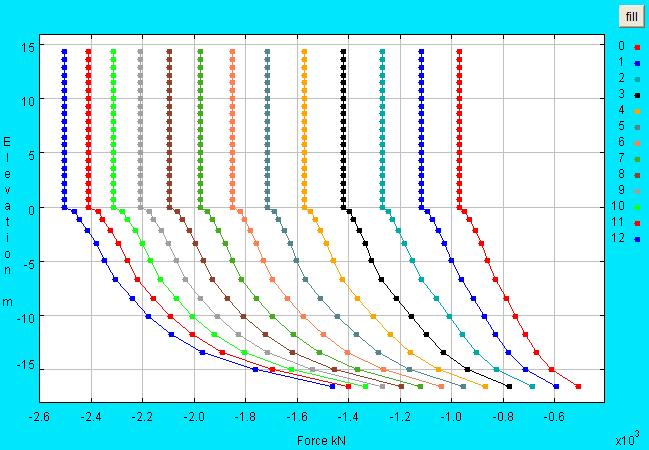
6 the highest tensile axial force (2,9 kn). The peak longitudinal moment is 12,92 kn-m at the pile cap and - 6,226 kn-m (at 4.9 m below the mudline), and the peak longitudinal shear is 1,163 kn. Compared to pile # 1, the corner back pile (#9) carries a slightly higher shear force and a significantly larger axial load (in tension). Elevation (m) Elevation (m) Elevation (m) Pile #16 Pile # D Long (m) Pile #16 Pile #8 1 1 V Long (x1 3 kn) a) F InitVert (x1 3 kn) F Vert (x1 3 kn) Mudline M Long (x1 3 kn m).3.29 D Vert (m) Fig. 6. Response profiles of front piles (see Fig. 3 for pile group layout; D Long : longitudinal displacement; V Long : longitudinal shear force; M Long : bending moment in the longitudinal plane; F InitVert : axial force due to gravity; F Vert : axial force; D Vert : vertical displacement) Pile #9 Pile # D Long (m) 1 1 V Long (x1 3 kn) a) Mudline M Long (x1 3 kn m) Elevation (m) Pile #9 Pile # F InitVert (x1 3 kn) F Vert (x1 3 kn) D Vert (m) Fig. 7. Response profiles of back piles (see Fig. 3 for pile group layout; D Long : longitudinal displacement; V Long : longitudinal shear force; M Long : bending moment in the longitudinal plane; F InitVert : axial force due to gravity; F Vert : axial force; D Vert : vertical displacement). Loading History The pile cap displacement of.12 m was applied in 12 steps. Response profiles of the pile experiencing the highest moment and shear (the corner front pile #16, Fig. 3) are shown in Fig. 8. Below the mudline, maximum moment and shear location is seen to propagate downwards with the level of applied lateral deformation (due to soil yielding at the upper layers of the stratum). Axial Force Distribution The axial force distribution between piles in the pile group is shown in Table 3 (along with the initial dead load counterpart). Even in the initial static state, the share of each pile varies in a wide range. Piles along the circumference carry most of the load with the corner piles shoulder the biggest burden. The inner piles (#s 2-7) hardly see much of the applied dead load. At the prescribed.12m longitudinal pile cap displacement, the compressive axial forces increase dramatically in the front piles (#s 4-8 and 12-16). Conversely, the back piles experience tensile forces reaching a maximum of about 29 kn in the back corner pile # 9. Figs display the axial force load history profiles for selected piles. In each figure, similarly located front and back pile responses are compared. Compressive forces are seen to gradually increase in the front piles, while the back piles eventually experience substantial tensile axial forces. Evolution of axial load transfer mechanism from the pile to the surrounding soil during the loading process may be also observed. Paper No. 5.54a 5
 F Vert /F verts * (kn) F InitVert /F verts * 1 1933-2.1-1251 1.4 2 418.6 -.5-378.2.4 3 8.995 -. -269.4.3 4-4.9.4-251.4.3 5-699.1.8-251.4.3 6-938 1. -269.5.3 7-1244 1.")
 REPRESENTATIVE SINGLE PILE REFERENCE SIMULATION For comparison, a single fixed head pile was also studied.")
7 a) Table 3. Axial force distribution by pile for pile-cap longitudinal displacement at.12 m (and the initial dead load counterpart). F Vert F InitVert Pile # (kn) F Vert /F verts * (kn) F InitVert /F verts * Total * F verts is the single pile dead load (F verts = kn) REPRESENTATIVE SINGLE PILE REFERENCE SIMULATION For comparison, a single fixed head pile was also studied. The geometrical and material properties of this pile are identical to those of any of the piles in the pile group. The imposed dead load was kn (= -289 kn / 32 piles). The pile cap longitudinal displacement was applied up to.12 m. A half mesh configuration was used (Fig. 13). Length of the mesh in the longitudinal direction is 192 m, with 96 m transversally (in this half-mesh configuration, resulting in a 192 m x 192 m soil domain simulation in plan view). The soil layer thickness (43.9 m) and properties are the same as those of the pile group case (the bottom of the soil domain is 27.4 m below the pile tip). Half of the dead load ( kn) was applied in this half mesh configuration due to symmetry. Summary of Main Results c) Fig. 8. Response profiles for Pile #16 (see Fig. 3c for pile group layout): a) longitudinal displacement; longitudinal bending moment; c) longitudinal shear force. Overall response Fig. 14 shows the lateral load versus pile head displacement. A lateral load of 2,637 kn (representative of the full mesh configuration) was reached at the pile head longitudinal displacement of.12 m. Paper No. 5.54a 6
 Corner")

 ( Fig. 1.")


8 (a) ( Fig. 9. Axial force profile: a) Corner Pile # 9, and Corner Pile # 16 (see Fig. 3c for pile group layout). (a) ( Fig. 1. Axial force profile: a) Edge Central Pile # 1, and Edge Central Pile # 8 (see Fig. 3c for pile group layout). (a) ( Fig. 11. Axial force profile: a) Edge Pile # 11, and Edge Pile # 14 (see Fig. 3c for pile group layout). Paper No. 5.54a 7


. Evolution of the axial load transfer mechanism into the surrounding soil is also evident in Fig. 16d 3 25 2 Load (kn) 15 1 5.2.4.6.8.1.12 Pile head displacement (m) Fig.")
, and the peak longitudinal shear is -2,637 kn (at and above the mudline).")
9 (a) ( Fig. 12. Axial force profile: a)inner Pile # 3, and Inner Pile # 6 (see Fig. 3c for pile group layout). deformed mesh is shown in Fig. 15, where the pattern of soil yielding may be contrasted with its pile group counterpart of Fig. 5a. In view of the close pile group spacing, the soil surrounding the pile group (Fig. 5a) exhibits a higher level of overall yielding Loading History Fig. 13. Finite element mesh of the single pile model. At the 14.3 m elevation above the mudline, pile head displacement of up to.12 m was applied in 12 steps, and the response profiles are shown in Fig. 16. As noted earlier in the pile group scenario, location of peak moment and shear below the mudline moves lower with the increase in applied longitudinal displacement (due to soil yielding in the upper highly stressed strata). Evolution of the axial load transfer mechanism into the surrounding soil is also evident in Fig. 16d Load (kn) Pile head displacement (m) Fig. 14. Load-displacement curve for the single pile analysis The peak longitudinal moment is 28,573 kn-m at the pile cap and -14,233 kn-m (at 3.8 m below mudline), and the peak longitudinal shear is -2,637 kn (at and above the mudline). As such, it may be noted that the single pile sustained over twice the shear and moment of the front corner pile # 16. The final Fig. 15. Stress ratio contour fill for the single pile case at the final step (red color shows yielded soil elements; factor: 5) Paper No. 5.54a 8


10 a) d) Fig. 16. Response profiles for the single pile: a) longitudinal displacement; bending moment at the longitudinal plane; c) longitudinal shear force; d) axial force. SOIL-PILE INTERFACE MECHANISM In the conducted simulations, no effort was made to address the important issue of modeling the interface behavior between the soil and the pile. For instance, a gap would be expected to develop as the pile gradually moves laterally away from the adjacent soil behind it. Such mechanisms are worthy of further investigation, and stand to influence the computational simulation outcomes. SUMMARY AND CONCLUSIONS A pilot computational study of a large pile group system under lateral load was presented. A highly idealized linear pile response was assumed, embedded within a 3-layer stratified soil stratum represented by J 2 elasto-plastic behavior. The open-source platform OpenSees was employed throughout. The reported pre- and post-processing scenarios are generated by the user interface OpenSeesPL, a robust and versatile framework for computational analysis of pile-ground systems. Displacement in the longitudinal direction was applied to the group at the pile cap elevation. A single pile scenario was also studied for comparison. The conducted investigations aim to highlight the analysis framework capabilities and range of potential applications. Overall, the computed results indicate: 1. Corner piles carry a significantly higher proportion of the applied axial load. c) 2. Due to application of lateral load, back piles experience a significant reduction in axial load, resulting eventually in occurrence of tensile axial forces. Such change in axial load may adversely affect the stiffness and strength of the structural materials (reinforced concrete). Paper No. 5.54a 9
11 3. The front piles may have to support a substantial increase in axial compressive load, along with the imposed bending moment and shear forces. 4. With close pile spacing (of the order of 2 pile diameters), piles along the circumference of the 4x8 pile group end up carrying most of the static and dynamic loads. 5. At an equal level of applied longitudinal displacement, a large soil domain was yielded in the vicinity of the pile group, compared to the single pile scenario. 6. Additional field data and numerical/experimental investigations are needed to further refine and verify the presented analysis procedures, including the soil-pile interface characteristics, effects of pile driving/installation, mesh refinement, and nonlinear pile and soil responses. ACKNOWLEDGMENTS The authors are grateful for the funding provided by the Pacific Earthquake Engineering Research (PEER) Center under NSF Award Number EEC , the PEER Lifelines program, and the NSF grant No. OCI REFERENCES Elgamal, A., Yang, Z., Parra, E., and Ragheb, A. 23. Modeling of cyclic mobility in saturated cohesionless soils. International Journal of Plasticity, 19(6), Elgamal, A. Lu, J., and Forcellini, D. 29. Mitigation of liquefaction-induced lateral deformation in a sloping stratum: 3D numerical simulation, Journal of Geotechnical and Geoenvironmental Engineering, 135(11), Lu, J., Yang, Z., and Elgamal, A. 26. OpenSeesPL threedimensional lateral pile-ground interaction version 1. user's manual, Report No. SSRP-6/3, Department of Structural Engineering, University of California, San Diego, La Jolla, CA. Mazzoni, S., McKenna, F., and Fenves, G. L. 26. Open system for earthquake engineering simulation user manual, Pacific Earthquake Engineering Research Center, University of California, Berkeley ( Yang, Z., Elgamal, A., and Parra, E. 23. A computational model for cyclic mobility and associated shear deformation, Journal of Geotechnical and Geoenvironmental Engineering, 129(12), Paper No. 5.54a 1
Geotechnical and SSI Simulations
 Geotechnical and SSI Simulations Ahmed Elgamal Jinchi Lu Zhaohui Yang 1 Yuyi Zhang, Joel P. Conte, Zhaohui Yang, Ahmed Elgamal, Jacobo Bielak, and Gabriel Acero, Two- Dimensional Nonlinear Earthquake Response
INFLUENCE OF BNWF SOIL MODELLING ON DYNAMIC BEHAVIOUR OF PILE FOUNDATION FOR RC FRAME WITH STRUCTURAL WALL
 ICOVP, 3 th International Conference on Vibration Problems 29 th November 2 nd December, 27, Indian Institute of Technology Guwahati, INDIA INFLUENCE OF BNWF SOIL MODELLING ON DYNAMIC BEHAVIOUR OF PILE
Performance based Displacement Limits for Reinforced Concrete Columns under Flexure
 Performance based Displacement Limits for Reinforced Concrete Columns under Flexure Ahmet Yakut, Taylan Solmaz Earthquake Engineering Research Center, Middle East Technical University, Ankara,Turkey SUMMARY:
Fagà, Bianco, Bolognini, and Nascimbene 3rd fib International Congress
 COMPARISON BETWEEN NUMERICAL AND EXPERIMENTAL CYCLIC RESPONSE OF ALTERNATIVE COLUMN TO FOUNDATION CONNECTIONS OF REINFORCED CONCRETEC PRECAST STRUCTURES Ettore Fagà, Dr, EUCENTRE, Pavia, Italy Lorenzo
Nonlinear Finite Element Modeling & Simulation
 Full-Scale Structural and Nonstructural Building System Performance during Earthquakes & Post-Earthquake Fire A Joint Venture between Academe, Industry and Government Nonlinear Finite Element Modeling
BEHAVIOR OF REINFORCED CONCRETE BEAM WITH OPENING
 International Journal of Civil Engineering and Technology (IJCIET) Volume 8, Issue 7, July 2017, pp. 581 593, Article ID: IJCIET_08_07_062 Available online at http:// http://www.iaeme.com/ijciet/issues.asp?jtype=ijciet&vtype=8&itype=7
Earthquake Design of Flexible Soil Retaining Structures
 Earthquake Design of Flexible Soil Retaining Structures J.H. Wood John Wood Consulting, Lower Hutt 207 NZSEE Conference ABSTRACT: Many soil retaining wall structures are restrained from outward sliding
Nonlinear Models of Reinforced and Post-tensioned Concrete Beams
 111 Nonlinear Models of Reinforced and Post-tensioned Concrete Beams ABSTRACT P. Fanning Lecturer, Department of Civil Engineering, University College Dublin Earlsfort Terrace, Dublin 2, Ireland. Email:
CHAPTER 3 ANALYSIS METHOD
 CHAPTER 3 ANALYSIS METHOD 3.1 ELASTIC STATIC ANALYSIS Elastic static analysis is done to calculate stress ratio between before and after subsidence. The structure will behave elastic when the first yield
NON-LINEAR STRUCTURAL INTEGRITY ANALYSIS
 NON-LINEAR STRUCTURAL INTEGRITY ANALYSIS AHMAD RAHIMIAN, PhD, PE, SE Dr. Ahmad Rahimian., PE, SE is President of Cantor Seinuk Structural Engineers in New York City. An expert in the behaviour of steel
Nonlinear Analysis of Shear Dominant Prestressed Concrete Beams using ANSYS
 Nonlinear Analysis of Shear Dominant Prestressed Concrete Beams using ANSYS Job Thomas Indian Institute of Science, Bangalore, India Ananth Ramaswamy Indian Institute of Science, Bangalore, India Abstract
Journal of Asian Scientific Research EVALUATION OF RECTANGULAR CONCRETE-FILLED STEEL-HOLLOW SECTION BEAM-COLUMNS
 Journal of Asian Scientific Research journal homepage: http://www.aessweb.com/journals/5003 EVALUATION OF RECTANGULAR CONCRETE-FILLED STEEL-HOLLOW SECTION BEAM-COLUMNS Kamyar Bagherinejad 1 ---- Emad Hosseinpour
Council on Tall Buildings
 Structure Design of Sino Steel (Tianjin) International Plaza Xueyi Fu, Group Chief Engineer, China Construction Design International 1 1 Brief of Project 2 Location: Tianjin Xiangluowan Business District
PILE RAFT FOUNDATION BEHAVIOR WITH DIFFERENT PILE DIAMETERS
 4 th International Conference on Earthquake Geotechnical Engineering June 25-28, 2007 Paper No. 1114 PILE RAFT FOUNDATION BEHAVIOR WITH DIFFERENT PILE DIAMETERS Reza ZIAIE_MOAYED 1, Meysam SAFAVIAN 2 ABSTRACT
Simi Aboobacker 1 and Nisha Varghese 2
 Numerical Simulation of Special Concentrically Braced Frame Structure using OpenSEES Simi Aboobacker 1 and Nisha Varghese 2 PG Student, Dept. of Civil Engineering, Vidya Academy of Science and Technology,
Dynamic Stability of Elastomeric Bearings at Large Displacement
 Dynamic Stability of Elastomeric Bearings at Large Displacement A. Masroor, J. Sanchez, G. Mosqueda University at Buffalo, NY, USA K. L. Ryan University of Nevada, Reno, USA SUMMARY: Bearings used in the
Effect of beam dimensions on structural performance of wide beam-column joints
 Effect of beam dimensions on structural performance of wide beam-column joints J.S. Kuang 1) and *Wing Shan Kam 2) 1), 2) Department of Civil and Environmental Engineering, Hong Kong University of Science
Influence of Orientation of Piles on Seismic Response of Pile Groups
 International Journal of Civil Engineering Research. ISSN 2278-3652 Volume 5, Number 3 (2014), pp. 261-268 Research India Publications http://www.ripublication.com/ijcer.htm Influence of Orientation of
Nonlinear Redundancy Analysis of Truss Bridges
 Nonlinear Redundancy Analysis of Truss Bridges Analysis Report Dr. Michel Ghosn Ph.D. Graziano Fiorillo The City College of New York / CUNY SEPTEMBER 2013 Acknowledgments This section describes the redundancy
Numerical Modeling of Dynamic Soil-Structure Interaction in Bridges with HP Driven Piles
 Numerical Modeling of Dynamic Soil-Structure Interaction in Bridges with HP Driven Piles Yu Bao, Andrew Rietz and Steven Halewski, Rochester Institute of Technology, Rochester, NY, USA HP-Pile foundations
Seismic Analysis of Truss Bridges with Tall Piers
 Journal P Krishi Sanskriti Publications http: Seismic Analysis of Truss Bridges with Tall Piers Akil Ahmed 1 and Jameel Ahmed 2 1,2 Deptt of Civil Engineering Jamia Millia Islamia, Jamia Nagar, New Delhi
Compressive strength of double-bottom under alternate hold loading condition
 Compressive strength of double-bottom under alternate hold loading condition J.M. Gordo CENTEC, IST, University of Lisbon, Portugal ABSTRACT: The alternate bending of the bottom structure of a ship as
NON-LINEAR FEM ANALYSIS FOR CES SHEAR WALLS
 1NCEE Tenth U.S. National Conference on Earthquake Engineering Frontiers of Earthquake Engineering July 21-25, 214 Anchorage, Alaska NON-LINEAR FEM ANALYSIS FOR CES SHEAR WALLS S. SUZUKI 1, H. KURAMOTO
Modelling shearing characteristics of reinforced concrete
 University of Wollongong Research Online Faculty of Engineering - Papers (Archive) Faculty of Engineering and Information Sciences 2005 Modelling shearing characteristics of reinforced concrete Hossein
Over the last decade, drilled and postgrouted micropile foundations have
 Seismic Design of Micropile Foundation Systems Leo Panian, S.E., and Mike Korolyk, S.E. Over the last decade, drilled and postgrouted micropile foundations have come to be increasingly relied on for resisting
Recent Advances in Non-Linear Soil-Structure Interaction Analysis using LS-DYNA
 Recent Advances in Non-Linear Soil-Structure Interaction Analysis using LS-DYNA Michael Willford Arup, San Francisco, USA Richard Sturt Arup, London, UK Yuli Huang Arup, San Francisco, USA Ibrahim Almufti
Influence of Vertical Acceleration on Seismic Response of Endbearing
 American Journal of Engineering Research (AJER) e-issn : 2320-0847 p-issn : 2320-0936 Volume-4 pp-33-41 www.ajer.org Research Paper Open Access Influence of Vertical Acceleration on Seismic Response of
SHAKE TABLE TESTING OF BRIDGE REINFORCED CONCRETE COLUMNS UNDER COMBINED ACTIONS
 SHAKE TABLE TESTING OF BRIDGE REINFORCED CONCRETE COLUMNS UNDER COMBINED ACTIONS Juan G. Arias Acosta, Graduate Student David H. Sanders, Professor and Project PI University of Nevada, Reno NEESR SG 53737
BEARING CAPACITY IMPROVEMENT USING MICROPILES A CASE STUDY
 BEARING CAPACITY IMPROVEMENT USING MICROPILES A CASE STUDY G.L. Sivakumar Babu 1, B. R.Srinivasa Murthy 2, D.S. N. Murthy 3, M.S. Nataraj 4 ABSTRACT Micropiles have been used effectively in many applications
Seismic Performance and Design of Linked Column Frame System (LCF)
") Seismic Performance and Design of Linked Column Frame System (LCF) M. Malakoutian & J.W. Berman Department of Civil and Environmental Engineering, University of Washington, Seattle, WA, USA P. Dusicka
Seismic Performance and Design of Linked Column Frame System (LCF) M. Malakoutian & J.W. Berman Department of Civil and Environmental Engineering, University of Washington, Seattle, WA, USA P. Dusicka
Design of large scale wind turbine towers in seismic areas
 Design of large scale wind turbine towers in seismic areas C.C. Baniotopoulos, I. Lavassas, G. Nikolaidis, P.Zervas Institute of Metal Structures, Dept. of Civil Engineering, A.U.Th., Thessaloniki, Greece
Compressive strength of double-bottom under alternate hold loading condition
 Progress in the Analysis and Design of Marine Structures Guedes Soares & Garbatov (Eds) 017 Taylor & Francis Group, London, ISBN 978-1-138-06907-7 Compressive strength of double-bottom under alternate
Non Linear Analysis of Composite Beam Slab Junction with Shear Connectors using Ansys.16
 International Journal of Engineering Science Invention ISSN (Online): 2319 6734, ISSN (Print): 2319 6726 Volume 5 Issue 4 April 2016 PP.22-29 Non Linear Analysis of Composite Beam Slab Junction with Shear
FINITE ELEMENT ANALYSIS OF REINFORCED CONCRETE BRIDGE PIER COLUMNS SUBJECTED TO SEISMIS LOADING
 FINITE ELEMENT ANALYSIS OF REINFORCED CONCRETE BRIDGE PIER COLUMNS SUBJECTED TO SEISMIS LOADING By Benjamin M. Schlick University of Massachusetts Amherst Department of Civil and Environmental Engineering
Design check of BRBF system according to Eurocode 8 Use of pushover analysis
 2010 Design check of BRBF system according to Eurocode 8 Use of pushover analysis This report presents a simple computerbased push-over analysis for a steel structure with Buckling Restrained Braced Frame
ADAPT-PT 2010 Tutorial Idealization of Design Strip in ADAPT-PT
 ADAPT-PT 2010 Tutorial Idealization of Design Strip in ADAPT-PT Update: April 2010 Copyright ADAPT Corporation all rights reserved ADAPT-PT 2010-Tutorial- 1 Main Toolbar Menu Bar View Toolbar Structure
Deformation Capacity of RC Structural Walls without Special Boundary Element Detailing
 Proceedings of the Tenth Pacific Conference on Earthquake Engineering Building an Earthquake-Resilient Pacific 6-8 November 2015, Sydney, Australia Deformation Capacity of RC Structural Walls without Special
A THREE DIMENSIONAL STUDY OF THE EFFECT OF SOIL EROSION ON RIGID PIPES
 North American Society for Trenchless Technology (NASTT) No-Dig Show 2011 Washington, D.C. March 27-31, 2011 Paper F-1-04 A THREE DIMENSIONAL STUDY OF THE EFFECT OF SOIL EROSION ON RIGID PIPES Sherif Kamel
REHABILITATION OF RC BUILDINGS USING STRUCTURAL WALLS
 REHABILITATION OF RC BUILDINGS USING STRUCTURAL WALLS Ahmed GHOBARAH 1 And Maged YOUSSEF 2 SUMMARY A developed macroscopic model is applied to the analysis of an example structure to demonstrate the use
STUDY ON MODELING OF STEEL RIGID FRAME BRIDGE FOR DYNAMIC ELASTO-PLASTIC ANALYSIS
 STUDY ON MODELING OF STEEL RIGID FRAME BRIDGE FOR DYNAMIC ELASTO-PLASTIC ANALYSIS 83 Tsutomu YOSHIZAWA 1, Masaru NARITOMI 2, Osamu ISHIBASHI 3 And Masahide KAWAKAMI 4 SUMMARY The modeling method of the
Numerical Analysis of a Novel Piling Framed Retaining Wall System
 The 12 th International Conference of International Association for Computer Methods and Advances in Geomechanics (IACMAG) 1-6 October, 2008 Goa, India Numerical Analysis of a Novel Piling Framed Retaining
DESIGN FOR PROGRESSIVE COLLAPSE 1
 Your Partner in Structural Concrete Design TN447_progressive_collapse_110713 DESIGN FOR PROGRESSIVE COLLAPSE 1 Bijan O Aalami 2 This Technical Note outlines the design of column-supported conventionally
Seismic Fragility of Concrete Bridges with Deck Monolithically Connected to the Piers or Supported on Elastomeric Bearings
 Seismic Fragility of Concrete Bridges with Deck Monolithically Connected to the Piers or Supported on Elastomeric Bearings G. Tsionis & M.N. Fardis University of Patras, Greece SUMMARY: The seismic vulnerability
Linear and Nonlinear Seismic Analysis of a Tall Air Traffic Control (ATC) Tower
 Tower") Linear and Nonlinear Seismic Analysis of a Tall Air Traffic Control (ATC) Tower A. Adnan, M. Vafaei & A.K. Mirasa Faculty of Civil Engineering, Universiti Teknologi Malaysia SUMMARY: Air Traffic Control
Linear and Nonlinear Seismic Analysis of a Tall Air Traffic Control (ATC) Tower A. Adnan, M. Vafaei & A.K. Mirasa Faculty of Civil Engineering, Universiti Teknologi Malaysia SUMMARY: Air Traffic Control
INTERNATIONAL JOURNAL OF PURE AND APPLIED RESEARCH IN ENGINEERING AND TECHNOLOGY
 INTERNATIONAL JOURNAL OF PURE AND APPLIED RESEARCH IN ENGINEERING AND TECHNOLOGY A PATH FOR HORIZING YOUR INNOVATIVE WORK SPECIAL ISSUE FOR NATIONAL LEVEL CONFERENCE "SUSTAINABLE TECHNOLOGIES IN CIVIL
SOIL PRESSURE IN EMBANKMENT STABILIZATIONS
 SOIL PRESSURE IN EMBANKMENT STABILIZATIONS Analysis of the 3D shadowing effect of piles Dipl.-Ing. M. Filus Fides DV-Partner GmbH ABSTRACT: Pile checks required by the codes alone are usually not sufficient
Inelastic Versus Elastic Displacement-Based Intensity Measures for Seismic Analysis
 IACSIT International Journal of Engineering and Technology, Vol., No., December Inelastic Versus Elastic Displacement-Based Intensity Measures for Seismic Analysis L. Lin and Y. L. Gao, Member, IACSIT
Practical Nonlinear Analysis for Limit Design of Reinforced Masonry Walls
 Send Orders of Reprints at reprints@benthamscience.org The Open Civil Engineering Journal, 12, 6, 107-118 107 Open Access Practical Nonlinear Analysis for Limit Design of Reinforced Masonry Walls Andres
Pile to Slab Bridge Connections
 Pile to Slab Bridge Connections Mohamed I. Ayoub 1, David H. Sanders 2 and Ahmed Ibrahim 3 Abstract Slab bridges are a common bridge type, where the pile extends directly from the ground to the superstructure.
LATERAL LOAD BEHAVIOR OF UNBONDED POST-TENSIONED HYBRID COUPLED WALLS. Qiang SHEN Graduate Research Assistant. Yahya C. KURAMA Assistant Professor
 LATERAL LOAD BEHAVIOR OF UNBONDED POST-TENSIONED HYBRID COUPLED WALLS Qiang SHEN Graduate Research Assistant Yahya C. KURAMA Assistant Professor University of Notre Dame, Civil Engineering and Geological
Ensuring sufficient robustness to resist
 Performance of precast concrete moment frames subjected to column removal: Part 2, computational analysis Yihai Bao, Joseph A. Main, H. S. Lew, and Fahim Sadek This paper presents a computational study
ADAPT-PTRC 2016 Getting Started Tutorial ADAPT-PT mode
 ADAPT-PTRC 2016 Getting Started Tutorial ADAPT-PT mode Update: August 2016 Copyright ADAPT Corporation all rights reserved ADAPT-PT/RC 2016-Tutorial- 1 This ADAPT-PTRC 2016 Getting Started Tutorial is
SEISMIC RETROFIT OF A TYPICAL REINFORCED CONCRETE BUILDING THROUGH FRP JACKETING OF EXTENDED RECTANGULAR COLUMNS
 6 th International Conference on Advanced Composite Materials in Bridges and Structures 6 ième Conférence Internationale sur les matériaux composites d avant-garde pour ponts et charpentes Kingston, Ontario,
NON-LINEAR STATIC PUSHOVER ANALYSIS FOR MULTI-STORED BUILDING BY USING ETABS
 NON-LINEAR STATIC PUSHOVER ANALYSIS FOR MULTI-STORED BUILDING BY USING ETABS Polupalli Victor Paul 1, K Sampath Kumar 2 1 PG Student, Dept of Civil Engineering, Nova College of Engineering & Technology,
INTERNATIONAL JOURNAL OF CIVIL AND STRUCTURAL ENGINEERING Volume 2, No 2, 2011
 INTERNATIONAL JOURNAL OF CIVIL AND STRUCTURAL ENGINEERING Volume 2, No 2, 2011 Copyright 2010 All rights reserved Integrated Publishing services Research article ISSN 0976 4399 Solution of Shear Wall Location
Numerical Modeling of Slab-On-Grade Foundations
 Numerical Modeling of Slab-On-Grade Foundations M. D. Fredlund 1, J. R. Stianson 2, D. G. Fredlund 3, H. Vu 4, and R. C. Thode 5 1 SoilVision Systems Ltd., 2109 McKinnon Ave S., Saskatoon, SK S7J 1N3;
Experimental and Analytical Forensic Investigation of Bridge Timber Piles under Eccentric Loads
 98 Experimental and Analytical Forensic Investigation of Bridge Timber Piles under Eccentric Loads Daniel J. Borello 1, Bassem Andrawes 2, Jerome F. Hajjar 3, Scott M. Olson 4 1 Newmark Civil Engineering
Finite Element Modeling of New Composite Floors Having Cold-Formed Steel and Concrete Slab
 Missouri University of Science and Technology Scholars' Mine International Specialty Conference on Cold- Formed Steel Structures (2014) - 22nd International Specialty Conference on Cold-Formed Steel Structures
NLFEA Fire Resistance of 3D System Ceiling Panel
 NLFEA Fire Resistance of 3D System Ceiling Panel Rajai Z. Al-Rousan 1 Department of Civil Engineering, Jordan University of Science and Technology, Irbid, Jordan E-mail: rzalrousn@just.edu.jo 2 Department
THE EXTENDED N2 METHOD IN SEISMIC DESIGN OF STEEL FRAMES CONSIDERING SEMI-RIGID JOINTS
 THE EXTENDED N2 METHOD IN SEISMIC DESIGN OF STEEL FRAMES CONSIDERING SEMI-RIGID JOINTS Paulina KROLO 1, Mehmed CAUSEVIC 2 and Mladen BULIC 3 ABSTRACT In this paper the nonlinear static seismic analysis
Introduction to Structural Analysis TYPES OF STRUCTURES LOADS AND
 AND Introduction to Structural Analysis TYPES OF STRUCTURES LOADS INTRODUCTION What is the role of structural analysis in structural engineering projects? Structural engineering is the science and art
Comparison of geotechnic softwares - Geo FEM, Plaxis, Z-Soil
 Comparison of geotechnic softwares - Geo FEM, Plaxis, Z-Soil Comparison du logiciel géotechnique Geo FEM, Plaxis, Z-Soil J. Pruška CTU in Prague FCE Department of Geotechnics, Prague, Czech Republic, Pruska@fsv.cvut.cz
A Case History of Super-Large Scale Bridge Pile Foundation in Soft Soil
 Missouri University of Science and Technology Scholars' Mine International Conference on Case Histories in Geotechnical Engineering (213) - Seventh International Conference on Case Histories in Geotechnical
Interaction between ductile RC perimeter frames and floor slabs containing precast units
 Interaction between ductile RC perimeter frames and floor slabs containing precast units R. C Fenwick,. J. Davidson and D.. N. Lau Department of Civil and Environmental Engineering, University of uckland.
Pull-Through Failure Tests of Thin Steel Roof Battens under Wind Uplift Loads
 Missouri University of Science and Technology Scholars' Mine International Specialty Conference on Cold- Formed Steel Structures (2014) - 22nd International Specialty Conference on Cold-Formed Steel Structures
Effect of Vertical Acceleration on Highway Bridges
 Effect of Vertical Acceleration on Highway Bridges Li-Hong Sheng 1 and Sashi Kunnath 2 ABSTRACT The objective of this research is to assessing the current provisions in SDC-2006 for incorporating vertical
PERFORMANCE STUDY OF RETROFITTED GRAVITY LOAD DESIGNED WALL FRAME STRUCTURES (SC-140)
") PERFORMANCE STUDY OF RETROFITTED GRAVITY LOAD DESIGNED WALL FRAME STRUCTURES (SC-140) *A. Ahmed 1, K. H. Tan 1 1 Department of Civil and Environmental Engineering National University of Singapore, Singapore,
PERFORMANCE STUDY OF RETROFITTED GRAVITY LOAD DESIGNED WALL FRAME STRUCTURES (SC-140) *A. Ahmed 1, K. H. Tan 1 1 Department of Civil and Environmental Engineering National University of Singapore, Singapore,
Behaviour of Concrete Filled Rectangular Steel Tube Column
 IOSR Journal of Mechanical and Civil Engineering (IOSR-JMCE) ISSN: 2278-1684 Volume 4, Issue 2 (Nov. - Dec. 2012), PP 46-52 Behaviour of Concrete Filled Rectangular Steel Tube Column Anil Kumar Patidar
High Performance and Efficiency of Joints in Precast Members
 High Performance and Efficiency of Joints in Precast Members M.J.Gopinathan #1, K.Subramanian #2, #1 Research Scholar, Anna University, Chennai, India #2 Professor and Head, Dept of Civil Engineering Coimbatore
SEISMIC CRACKING AND STRENGTHENING OF CONCRETE GRAVITY DAMS
 SEISMIC CRACKING AND STRENGTHENING OF CONCRETE GRAVITY DAMS Hongyuan ZHANG 1 And Tatsuo OHMACHI 2 SUMMARY Concrete gravity dams designed in compliance with the present specification are likely to experience
Forensic Engineering
 476 Experimental and Numerical Investigation on Resistance and Failure Behavior of Ductile Concrete-Filled Double-Skin Tube Columns Subjected to Post- Earthquake Fires Reza Imani, A.M.ASCE 1 ; Gilberto
E APPENDIX. The following problems are intended for solution using finite element. Problems for Computer Solution E.1 CHAPTER 3
 E APPENDIX Problems for Computer Solution The following problems are intended for solution using finite element analysis software. In general, the problems associated with Chapters 3, 4, and 9 can be solved
Appendix D.2. Redundancy Analysis of Prestressed Box Girder Superstructures under Vertical Loads
 Appendix D.2 Redundancy Analysis of Prestressed Box Girder Superstructures under Vertical Loads By Jian Yang, Giorgio Anitori, Feng Miao and Michel Ghosn Contents 1. Introduction...1 2. Prestressed Concrete
ULTIMATE LOAD-CARRYING CAPACITY OF SELF-ANCHORED CONCRETE SUSPENSION BRIDGE
 ULTIMATE LOAD-CARRYING CAPACITY OF SELF-ANCHORED CONCRETE SUSPENSION BRIDGE Meng Jiang*, University of Technology Dalian, P. R. China Wenliang Qiu, University of Technology Dalian, P. R. China Lihua Han,
Methodology for design of earthquake resistant steel liquid storage tanks
 Earthquake Resistant Engineering Structures V 699 Methodology for design of earthquake resistant steel liquid storage tanks M. A. Haroun & M. A. Al-Kashif University of California, Irvine, and American
REVIEW ON SHEAR SLIP OF SHEAR KEYS IN BRIDGES
 REVIEW ON SHEAR SLIP OF SHEAR KEYS IN BRIDGES Benjamin Raison R; Freeda Christy C PG student, School of Civil Engineering, Karunya University. Associate Professor, School of Civil Engineering, Karunya
INTERNATIONAL JOURNAL OF CIVIL AND STRUCTURAL ENGINEERING Volume 2, No 2, 2011
 INTERNATIONAL JOURNAL OF CIVIL AND STRUCTURAL ENGINEERING Volume 2, No 2, 2011 Copyright 2010 All rights reserved Integrated Publishing services Research article ISSN 0976 4399 Nonlinear Seismic Behavior
Finite Element Study Using FE Code (PLAXIS) on the Geotechnical Behavior of Shell Footings
 on the Geotechnical Behavior of Shell Footings") Journal of Computer Science 2 (1): 104-108, 2006 ISSN 1549-3636 Science Publications Finite Element Study Using FE Code (PLAXIS) on the Geotechnical Behavior of Shell Footings Bujang B.K. Huat and Thamer
Journal of Computer Science 2 (1): 104-108, 2006 ISSN 1549-3636 Science Publications Finite Element Study Using FE Code (PLAXIS) on the Geotechnical Behavior of Shell Footings Bujang B.K. Huat and Thamer
ctbuh.org/papers CTBUH Recommendations for the Seismic Design of High-Rise Buildings
 ctbuh.org/papers Title: Author: Subject: CTBUH Recommendations for the Seismic Design of High-Rise Buildings Michael Willford, Council on Tall Buildings and Urban Habitat Structural Engineering Publication
ZANCO Journal of Pure and Applied Sciences
 ZANCO Journal of Pure and Applied Sciences The official scientific journal of Salahaddin University-Erbil ZJPAS (2016), 28 (6); 65-56 http://doi.org/10.21271/zjpas.28.6.7 Punching Strength of GFRP Reinforced
ELASTO-PLASTIC BEHAVIOR OF HORIZONTAL HAUNCHED BEAM-TO- COLUMN CONNECTION
 ELASTO-PLASTIC BEHAVIOR OF HORIZONTAL HAUNCHED BEAM-TO- COLUMN CONNECTION Naoki TANAKA 1, Yoshikazu SAWAMOTO 2 And Toshio SAEKI 3 SUMMARY In response to the 1995 Hyogoken-Nanbu earthquake, horizontal haunched
Effect of FRP strengthening on the behavior of shear walls with opening
 CICE 2010 - The 5th International Conference on FRP Composites in Civil Engineering September 27-29, 2010 Beijing, China Effect of FRP strengthening on the behavior of shear walls with opening M. Asfa
by Dr. Mark A. Ketchum, OPAC Consulting Engineers for the EERI 100 th Anniversary Earthquake Conference, April 17, 2006
 Principles of Earthquake Engineering of Bridges Part 1: Principles & Approach by Dr. Mark A. Ketchum, OPAC Consulting Engineers for the EERI 100 th Anniversary Earthquake Conference, April 17, 2006 Presentation
Seismic design of tunnels
 Seismic design of tunnels J-N. Wang', G.A. MunfakhZ 'Senior Professional Associate, Parsons Brinckerhoff Quade and Douglas, Inc. USA 'Senior Vice President, Parsons Brinckerhoff Quade and Douglas, Inc.
DISPLACEMENT-BASED SEISMIC DESIGN OF CONCRETE BRIDGES
 DISPLACEMENT-BASED SEISMIC DESIGN OF CONCRETE BRIDGES V.G. Bardakis 1 and M.N. Fardis 2 1 Post-Doctoral Researcher, Structures Lab, Dept. of Civil Engineering, University of Patras, Patras,Greece 2 Professor
An example of finite element modelling of progressive collapse
 COST Action TU0601 Robustness of Structures 2nd and 3rd of March 2009 Coimbra, Portugal An example of finite element modelling of progressive collapse Leslaw KWASNIEWSKI Marian A. GIZEJOWSKI Faculty of
Transactions, SMiRT-22 San Francisco, California, USA - August 18-23, 2013 Division V
 Transactions, SMiRT- San Francisco, California, USA - August 8-, SIMPLIFIED MODELING OF EFFECTS OF CONCRETE CRACKING ON OUT-OF-PLANE VIBRATIONS OF FLOORS Luben Todorovski, Mahmoud Khoncarly, Dan M Ghiocel,
DYNAMIC RESPONSE ANALYSIS OF THE RAMA 9 BRIDGE EXPANSION JOINT DUE TO RUNNING VEHICLE
 DYNAMIC RESPONSE ANALYSIS OF THE RAMA 9 BRIDGE EXPANSION JOINT DUE TO RUNNING VEHICLE Tanan Chub-uppakarn 1, Adison Owatsiriwong 2* 1 Department of Civil Engineering, Faculty of Engineering, Prince of
ANALYTICAL STUDIES OF A FULL-SCALE STEEL BUILDING SHAKEN TO COLLAPSE
 SDSS Rio STABILITY AND DUCTILITY OF STEEL STRUCTURES E. Batista, P. Vellasco, L. de Lima (Eds.) Rio de Janeiro, Brazil, September 8 -, ANALYTICAL STUDIES OF A FULL-SCALE STEEL BUILDING SHAKEN TO COLLAPSE
Overview of the Standard for Seismic Design of Cold-formed Steel Structural Systems - Special Bolted Moment Frames
 Missouri University of Science and Technology Scholars' Mine International Specialty Conference on Cold- Formed Steel Structures (2008) - 19th International Specialty Conference on Cold-Formed Steel Structures
Modeling of Coupled Nonlinear Shear and Flexural Responses in Medium-Rise RC Walls
 ing of Coupled Nonlinear Shear and Flexural Responses in Medium-Rise RC Walls Burak HOROZ 1, M.Fethi GÜLLÜ 2, and Kutay ORAKÇAL 3 1 Research Assistant Bogazici University, Istanbul, Turkey 2 Research Assistant
Seismic Evaluation of Steel Moment Resisting Frame Buildings with Different Hysteresis and Stiffness Models
 Seismic Evaluation of Steel Moment Resisting Frame Buildings with Different Hysteresis and Stiffness Models ABSTRACT : Jiwook Shin 1 and Kihak Lee 2* 1 M.S. student, Dept. of Architectural Engineering,
Overview of Presentation. SCBFs are Conceptually Truss Structures
 Ultimate Strength and Inelastic Behavior of Braced Frame Gusset Plate Connections Charles W. Roeder University of Washington Department of Civil and Environmental Engineering Seattle, WA 98195 Structural
INTERNATIONAL JOURNAL OF CIVIL AND STRUCTURAL ENGINEERING Volume 2, No 1, 2011
 INTERNATIONAL JOURNAL OF CIVIL AND STRUCTURAL ENGINEERING Volume 2, No 1, 2011 Copyright 2010 All rights reserved Integrated Publishing services Research article ISSN 0976 4399 Parametric study on Nonlinear
EXPERIMENTAL AND NUMERICAL SIMULATIONS OF COLLAPSE OF MASONRY ARCHES
 EXPERIMENTAL AND NUMERICAL SIMULATIONS OF COLLAPSE OF MASONRY ARCHES Łukasz Hojdys*, Tomasz Kamiński + & Piotr Krajewski* * Cracow University of Technology, Institute for Building Materials and Structures
Seismic Design of a Slope Stabilization Work Using Piles and Tendons
 6 th International Conference on Earthquake Geotechnical Engineering 1-4 November 2015 Christchurch, New Zealand Seismic Design of a Slope Stabilization Work Using Piles and Tendons H. Sanchez Lizarraga
Extreme Loading for Structures Version 3.1
 Extreme Loading for Structures Version 3.1 Corrosion Effects Option April 2010 1. Introduction Corrosion of gusset plates was identified as one of the main causes for failure in the catastrophic collapse
SEISMIC BEHAVIOR OF STEEL RIGID FRAME WITH IMPERFECT BRACE MEMBERS
 INTERNATIONAL JOURNAL OF CIVIL ENGINEERING AND TECHNOLOGY (IJCIET) International Journal of Civil Engineering and Technology (IJCIET), ISSN 976 638 (Print), ISSN 976 6316(Online), Volume 6, Issue 1, January
Modelling of RC moment resisting frames with precast-prestressed flooring system
 Modelling of RC moment resisting frames with precast-prestressed flooring system B.H.H. Peng, R.P. Dhakal, R.C. Fenwick & A.J. Carr Department of Civil Engineering, University of Canterbury, Christchurch.