ADAPT-PTRC 2016 Getting Started Tutorial ADAPT-PT mode
|
|
|
- Ashley Lang
- 6 years ago
- Views:
Transcription

1 ADAPT-PTRC 2016 Getting Started Tutorial ADAPT-PT mode Update: August 2016 Copyright ADAPT Corporation all rights reserved ADAPT-PT/RC 2016-Tutorial- 1
 the workflow applies to input of one-way slabs and beams.")
2 This ADAPT-PTRC 2016 Getting Started Tutorial is intended to be used as a practical example and guide for modeling a 2D post-tensioned two-way slab frame in the PT mode of the program. While the example is related to a specific system type (two-way slab) the workflow applies to input of one-way slabs and beams. For additional information, refer to the ADAPT-PTRC 2016 Getting Started Tutorial for RC mode and the ADAPT- PTRC 2016 User Manual. Both documents can be accessed from the HELP menu of the program. The example model is created with the help of a wizard which consists of different Input Forms. Each Input Form can be accessed at any time through the Menu Bar. The input that you provide on the Input Forms is displayed real-time in the Structure View. The view of the structure can be modified with the help of the View Toolbar which contains View Tools with which you can change the perspective, turn on and off components and zoom. The Main Toolbar contains Common Tools such as New Project, Open Project and Save Project. Main Toolbar Menu Bar Structure View Input Forms FIGURE 1: ADAPT-PT User Interface ADAPT-PT/RC 2016-Tutorial- 2
3 1 COLUMN-SUPPORTED SLAB (TWO-WAY SYSTEM) The objective of this tutorial is to explain how a floor strip or frame line is idealized from a complete floor system and modeled as a slab- or beam-frame ADAPT-PTRC This tutorial will demonstrate the step-by-step procedure in the PT mode of ADAPT- PTRC to generate data, analyze and design a column-supported slab which is a part of a floor system. A column-supported slab is generally considered as a two-way system. The tutorial covers the following features of the program: Generation of input data, using the simple Conventional option of the program. Design based on the post-tensioning effective force method, as opposed to selection of number of tendons. The structure selected is a typical design strip from a floor system. The geometry, material, loading and other particulars of the structure are given below. The geometry of the whole floor is shown in Figure 1-1. The design strip for this tutorial is shown hatched in Figure 1-2. FIGURE 1-1 ADAPT-PT/RC 2016-Tutorial- 3

4 FIGURE 1-2 The lengths and tributary widths of the spans of the design strip in orthogonal direction are shown in Figure 1-3. FIGURE 1-3 ADAPT-PT/RC 2016-Tutorial- 4
5 The elevation of the design strip is shown in Figure 1-4. FIGURE 1-4 The length of the spans of the design strip along support line 2 is shown in Figure 1-5. FIGURE 1-5 The idealized design strip is shown in Figure 1-6. FIGURE 1-6 ADAPT-PT/RC 2016-Tutorial- 5
6 MATERIAL PROPERTIES AND LOADING Thickness of slab = 10 inch (i) Material Properties o Concrete: Compressive strength, f c Weight Modulus of Elasticity = 4000 psi = 150 pcf = 3605 psi o Prestressing: Low Relaxation, Unbonded System Strand Diameter = 0.5 inch Strand Area = inch 2 Modulus of Elasticity = ksi Ultimate strength of strand, fpu = 270 ksi Minimum strand cover From top fiber = 1.5 inch From bottom fiber Interior spans = 1.5 inch Exterior spans = 2 inch o Nonprestressed Reinforcement: Yield stress, fy Modulus of Elasticity Minimum Rebar Cover = 60 ksi = ksi = 1 inch Top and Bottom (ii) Loading Superimposed Dead load = 30 psf (uniform) Live load = 50 psf (uniform) ADAPT-PT/RC 2016-Tutorial- 6

7 1.1 GENERATE THE STRUCTURAL MODEL When the program is launched from the desktop shortcut or from the computer START menu, the opening screen will appear as below. This screen gives you the option to select a design mode of Post-Tensioned or Mild Reinforced. For this tutorial, select the Post- Tensioned option and OK. This will open the PT mode of the program where the PT input forms are active and loaded. In the ADAPT-PT 2016 input screen, click the Options menu and set the Default Code as American-ACI318 (2014) / IBC 2015 and Default Units as American Edit the Project Information General Settings Open the new project by clicking either New on the File menu or the New Project button on the toolbar. This automatically opens the General Settings input screen, as in Figure You can enter the General Title and /or Specific Title of the project in that window. For the purpose of this tutorial, enter the General Title as Support Line 2. This will appear at the top of the first page of the output. Enter Specific Title as Two Way Slab. This will appear at the top of each subsequent page of the output. Next, select Geometry Input as Conventional. ADAPT-PT/RC 2016-Tutorial- 7


8 Next, select the Structural System as Two-Way slab. Then there is an option to include drop caps, transverse beam and/or drop panels. In this case select No. Select No for the option to Recommend Slab Thickness. Click Next at the bottom right of this screen to open the next input screen, Design Settings. FIGURE Design Code In the Design Code screen, set the code as American-ACI318 (2014) / IBC FIGURE ADAPT-PT/RC 2016-Tutorial- 8

9 Design Settings This screen is divided into three parts: Analysis options, Design options, and Contribution to unbalanced moment. In Analysis options, you can select various calculation settings. First, select the Execution Mode as Interactive. Next, select Yes for Reduce Moments to Face-of-Support option. Select No for the option to Redistribute moments. Select Yes for the Equivalent Frame Modeling. In Design options, check Use all provisions of the code that you have selected in the previous step. In Generate moment capacity based on, check Design Values. In Contribution to unbalanced moment, leave the contribution of Top isolated bars, and Bottom isolated bars, and Post-tensioning as default values (100 percent). FIGURE Click Next at the bottom right of the Design Settings screen to open the Span Geometry input screen. ADAPT-PT/RC 2016-Tutorial- 9

10 1.1.2 Edit the Geometry of the Structure Enter Span Geometry (Figure 1.1-4) FIGURE This screen is used to enter the cross-sectional geometry of the slab as per Figure 1-6. Set the Number of Spans as 4 either by clicking the up arrow or using CTRL +. Select the section, Sec, as Rectangular and edit ft for length, L, in for width, b, and 10 in for height, h, for SPAN 1. Similarly enter details for SPAN 2, 3, 4 and R-Cant as shown in Figure The widths (b) of each span are average tributary width for that span. As you enter the values, the span is displayed in real-time in the 3D window. The reference height (Rh) identifies the position of a reference line that is used to specify the location of the tendon. Typically, the reference height is set equal to the slab depth. Edit reference height, Rh as 10 in, i.e., slab depth, for all spans. The left and right multiplier columns (<-M and M->) are used to specify the tributary width to indicate how much of the tributary falls on either side of the support line. For this tutorial, tributary method is used, i.e., tributary widths are entered as width, b, and the ratio of the tributary width on either side of the support line is entered as the left and right multipliers. For SPAN 1, enter <-M and M-> as 0.47 and 0.53 respectively. Similarly enter details for SPAN 2, 3, 4 and R-Cant as shown in Figure ADAPT-PT/RC 2016-Tutorial- 10

11 FIGURE Click Next on the bottom line to open the next input screen Enter Support Geometry This screen is used to input column/wall heights, widths and depths. You may enter dimensions for columns/walls above and/or below the slab. Select the Both Columns from the support selection. Enter 9.02 ft for H1 and 9.84 ft for H2 in the typical row and press ENTER, since all the supports are the same height. Next, enter the dimensions of the supports. B is the dimension of the column/wall crosssection normal to the direction of the frame. D is the column/wall dimension parallel to the frame. Enter the given column/wall dimensions as in Figure On this input screen, you can select for each support whether the left edge and the right edge of that support is interior or exterior. In this case, all supports are interior as the span is an interior span. ADAPT-PT/RC 2016-Tutorial- 11

12 FIGURE Click Next on the bottom line to open the Supports Boundary Conditions input screen Enter Support Boundary Conditions This screen is used to enter support widths and column boundary conditions. Support widths can be entered if you answered Yes to the Reduce Moments to faceof- support question on the Design Settings screen, i.e., if you answered No, you cannot input values in the SW column. This input value will be used to calculate the reduced moments. Since the support width, SW, is set to the column/wall dimension (D) as a default, the SW values will be automatically determined from the support geometry and cannot be modified by the user. If you want to input the SW values, uncheck the SW=Column Dimension box. Select the boundary conditions for lower and upper columns as 1(fixed) from the drop down list. Leave the End Support Fixity for both the left and right supports as default No. This will be used when the slab or beam is attached to a stiff member. ADAPT-PT/RC 2016-Tutorial- 12

13 FIGURE Click Next at the bottom of the screen to open the input screen Loading Enter Data Edit the Loading Information Enter the span number as 1 in the Span column. If the loads are the same for all the spans, you can type ALL or all in the Span column. This will copy the data to all of the spans. If you choose not to include Self-weight, you now have the option to define the selfweight (SW) as a Class. In any case, you can choose to specify additional dead load as superimposed dead load (SDL) as a Class. PT/RC 2104 gives you the option to specify any load as an X Class. Select the Class as SDL from the drop down list and specify the load type as uniform either by typing U in L-? or by dragging the icon from the graphics of the uniform loading. The default of the load type when you select the load class is L-U; so leave it as is for this tutorial. Type 0.03 k/ft 2 (=30 psf) for superimposed dead load in the w column. You can enter DL with or without self-weight, since the program can calculate self-weight automatically. In order to calculate the self-weight automatically, you must answer Yes to Include Self- Weight question at the top right of the screen and enter 150 pcf as unit weight of concrete. ADAPT-PT/RC 2016-Tutorial- 13
 for all spans. Answer Yes to Skip Live Load? at the top left of the screen and enter the Skip Factor as 1 (Figure 1.1-8).")

14 Repeat the procedure for live load by entering the span number and changing the Class to LL and w value to 0.05 k/ft 2 (=50 psf) for all spans. Answer Yes to Skip Live Load? at the top left of the screen and enter the Skip Factor as 1 (Figure 1.1-8).. FIGURE If you go to any other form and navigate back to the Loads input form, you will see that the loading information is now entered in the table for each span (Figure 1.1-9). FIGURE Click Next at the bottom of the screen to open the Material - Concrete input screen. ADAPT-PT/RC 2016-Tutorial- 14

15 1.1.4 Edit the Material Properties Enter the Properties of Concrete Select Cylinder concrete strength at 28 days. Select the Normal weight and enter the strength at 28 days for slab/beam and column as 4000 psi. When you press Enter from the strength input value, the Modulus of Elasticity will be calculated automatically based on the concrete strength and the appropriate code formula. For this tutorial, keep the value of creep coefficient as 2. The creep coefficient will be used in the calculation of long-term deflection. Consider Concrete strength at stressing as 3000 psi. FIGURE Enter the Properties of Reinforcement In the section Longitudinal reinforcement, change the values for Yield Strength and Modulus of Elasticity to 60 ksi and ksi respectively. Change the Preferred Bar Sizes for Top and Bottom to 5 and 8 respectively. These will be used when calculating the number of bars required. In Shear reinforcement, select Stud (headed bar) and change Preferred Stud diameter, Yield strength shear reinforcement and the Number of rails per side to 0.5 inch, 60 ksi and 2 respectively. ADAPT-PT/RC 2016-Tutorial- 15


16 FIGURE Click Next at the bottom of the screen to open the next input screen Enter the Post-Tensioning System Parameters Select the Post-tensioning system as Unbonded and leave the default values of the other properties as they are as in Figure FIGURE Click Next at the bottom of the screen to open the input screen, Base Non-Prestressed Reinforcement. ADAPT-PT/RC 2016-Tutorial- 16

17 Edit Base Reinforcement The program allows you to specify a base reinforcement that is taken into consideration when designing the structure. Select Yes in the Base Reinforcement section. You have the choice between defining a mesh or isolated rebar. For this example choose Isolated from the drop down box. Next specify the span where your base reinforcement starts. For this example, let the rebar start at the beginning of span 1. Therefore, enter a 1 in First end location and a 0 in X1/L. If you want to specify the end of the reinforcement at the end of span number 4, define 4 for Second end location and 1 for X2/L. Furthermore, you specify 4 bars (Number) with Bar Size of 6 as Bottom bars with a Cover of 2 inch. FIGURE Click Next at the bottom of the screen to open the input screen, Criteria Allowable Stresses. ADAPT-PT/RC 2016-Tutorial- 17
. Leave the default values as they are. FIGURE 1.")
18 1.1.5 Edit the design criteria Enter the Initial and Final Allowable Stresses Tensile stresses are input as a multiple of the square root of f c, and compressive stresses are input as multiple of f c. The default values given in Figure are according to ACI 318 (2014). Leave the default values as they are. FIGURE Click Next at the bottom of the screen to open the next input screen, Criteria Recommended Post-Tensioning Values. ADAPT-PT/RC 2016-Tutorial- 18
 and")
19 Enter the Recommended Post-Tensioning Values This screen is used to specify minimum and maximum values for average precompression (P/A: total prestressing divided by gross cross-sectional area) and percentage of dead load to balance (Wbal). These values are used by the program to determine the post-tensioning requirements and the status of the Pmin/Pmax and WBAL Min/ Max indicators on the Recycle window. The values shown in Figure are according to the selected code and the experience of economical design. FIGURE Click Next at the bottom of the screen to open the input screen, Criteria Calculation Options Select the Post-Tensioning Design Option The two design options are Force Selection and Force/Tendon Selection, as in Figure Force Selection is the default option. Keep the default option. ADAPT-PT/RC 2016-Tutorial- 19

20 FIGURE In this option, a tendon will be assigned a final and constant effective force, equal to the jacking force minus all stress losses, expressed as a single value. For more information on the Calculated Force option, please refer to the ADAPT-PTRC 2016 User Manual. Click Next at the bottom of the screen to open the next input screen, Criteria Tendon Profile Specify the Tendon Profiles The program allows you to specify up to three tendon paths per span. You can define one profile for each of the three tendons. In the section Option for tendons you can define the Default extension of terminated tendon as fraction of span. Also, you can specify the Shape of tendon extension from the Left end and the Right end. For this example, leave the default values as shown in Figure ADAPT-PT/RC 2016-Tutorial- 20
.")
21 FIGURE Click Next at the bottom of the screen to open the next input screen, Criteria Minimum Covers Specify Minimum Covers for Post-Tensioning Tendons and Mild Steel Reinforcement The cover for the prestressing steel is specified to the center of gravity of the strand (cgs). Edit CGS of the tendon as 1.5 inch for both the top fiber and the interior spans of bottom fiber and 2.0 inch for the exterior spans for the bottom fiber. For nonprestressed reinforcement, edit 1.0 inch Cover for both the top and the bottom (as shown in Figure ). ADAPT-PT/RC 2016-Tutorial- 21
.")
22 FIGURE Click Next at the bottom of the screen to open the input screen, Criteria Minimum Bar Extension Specify Minimum Bar Length and Bar Extension of Mild Steel Reinforcement The values given as default for minimum bar lengths are according to ACI-318 (2014). Use the default values (as shown in Figure ). Note that the development length is user-defined and is the bar extension beyond point of zero moment where reinforcement is no longer required. The values entered for cut-off lengths are used to calculate top and bottom bar lengths when minimum reinforcement requirements govern. Note that where Rebar Curtailment is input, those settings will take priority over Minimum bar length settings. ADAPT-PT/RC 2016-Tutorial- 22

23 FIGURE Click Next at the bottom of the screen to open the input screen, Criteria Rebar Curtailment Specify Top and Bottom Rebar Curtailment Input for Spans The default values given for Long and Short Bars relative for length equal to fraction of span and % of area of required steel are according to Chapter 13 of ACI-318 (2014). Keep the default values (as shown in Figure and Figure ). Note that curtailment rules relative to the selected code are applied to top and bottom bars and are conservatively adjusted such that the bar lengths are equal on both sides of the support or equal at both sides of the center of span. Also, 2 bars are set as a minimum requirement. The reinforcement result output for this example will be based on the curtailment rules which take priority over reinforcement rules relative to the previous section for bar extensions. In the case where curtailment rules are not sufficient to the default solution (that solution related to the bar extension input) the reinforcement arrangement and length output will be given as that taken from the bar extension input. ADAPT-PT/RC 2016-Tutorial- 23

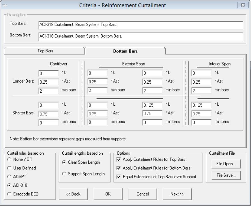
24 FIGURE FIGURE ADAPT-PT/RC 2016-Tutorial- 24
 / IBC 2015.")
25 Input Load Combinations Figure shows the screen which is used to input the load combination factors for service and strength (ultimate) load conditions. It is also used to enter any applicable strength reduction factors. The default values are according to the American-ACI318 (2014) / IBC The program allows you to specify four strength load combinations and four service load combinations. For American-ACI318 (2014) / IBC 2015, two of the service load combinations are reserved for sustained load and two for total load. For this example, do not include lateral loads. FIGURE SAVE AND EXECUTE THE INPUT DATA To save the input data and execute the analysis, either select Execute Analysis on the menu bar or click on the Save & Execute Analysis button. Then, give a file name and directory in which to save the file. Once the file is saved, the program will automatically execute the analysis by reading the data files and performing a number of preliminary data checks. Once the execution gets completed, the PT Recycling window, as shown in Figure opens. If an error is detected, the program will stop and display a message box indicating the most likely source of the error. ADAPT-PT/RC 2016-Tutorial- 25

26 FIGURE Here you can optimize the design by changing the tendon forces and tendon heights. Select 1-Single tendon path for the Force selection method. % DL balanced is close to the max limit of 125 for CL. For the 'Change the PT force to 500 kips for CL. The status indicator at the top right of the Recycle window will begin to flash as Recycle. Since we selected the Force Selection option during data entry, the program will only allow the Force Selection mode for execution. Once all of the changes are made as shown in Figure 1.2-2, click on the Recycle button to update all of the tabs, the Design Indicator box and the Recycle Graphs. ADAPT-PT/RC 2016-Tutorial- 26

27 FIGURE After the recalculation of the stresses and required forces along the member, based on the current values, the window, as shown in Figure 1.2-3, with the OK status for all items in the design indicator box opens. ADAPT-PT/RC 2016-Tutorial- 27

![by clicking Extreme fiber stresses [4] tab in](/docs-images/76/73748870/images/28-1.jpg "the PT Recycling window (Figure 1.2-4).")
28 FIGURE You can check the final stresses either by clicking Extreme fiber stresses [4] tab in the PT Recycling window (Figure 1.2-4). FIGURE ADAPT-PT/RC 2016-Tutorial- 28
. FIGURE 1.2-5 The top diagram, the Tendon Height Diagram shows the elevation of tendon profile selected.")
29 Graphs displays a set of three graphs which provide detailed information on the tendon profile, the tension and compression stresses and the required versus provided posttensioning forces at 1/20 th points along the spans (Figure 1.2-5). FIGURE The top diagram, the Tendon Height Diagram shows the elevation of tendon profile selected. Tendon profile can be viewed either with concrete outline or without concrete outline by checking the option at the left of the screen. The second diagram, Stress Diagrams, plots the maximum compressive and tensile stresses at the top and bottom face of the member. You can view the stresses due to e.g. Self weight, Superimposed Dead Load, Live Load, Post-tensioning and Sustained each separately, or in combination, by selecting the options at the screen. Also you can verify the top and bottom stresses due to the service combination with the allowable values. In Figure 1.2-5, it shows the final top fiber stresses with the allowable stresses. In which, gray color represents the allowable value, top curve represents the tensile stress and ADAPT-PT/RC 2016-Tutorial- 29

30 bottom curve represents the compressive stress. If the calculated stress is not within the limit, i.e., the top or bottom curve is outside the gray portion; you need to modify the forces to optimize the design. The third diagram, Post-Tensioning Diagrams shows the required and provided posttensioning force at 1/20th points along each span. The vertical line represents the required post-tensioning and the horizontal line represents the provided post-tensioning at that section. At each design section along a span, the program performs an analysis based on the post-tensioning force at that section Required and provided PT force [2] tab in the PT Recycling window shows PT forces provided in the left, center and right region of each span as well as the forces required in each region for minimum P/A, Wbal %DL and allowable tensile stresses (Figure 1.2-6). FIGURE Required PT force [3] tab in the PT Recycling window shows the required PT forces for only the most recently calculated profile. (Figure 1.2-7). ADAPT-PT/RC 2016-Tutorial- 30
![FIGURE 1.2-7 Note that in this example, Tendon selection and extents [5] tab in the PT Recycling window is inactive, as single-tendon path has been chosen.](/docs-images/76/73748870/images/31-0.jpg "If the solutions are not acceptable, you can change post-tensioning layout and recycle until an acceptable solution is reached.")
31 FIGURE Note that in this example, Tendon selection and extents [5] tab in the PT Recycling window is inactive, as single-tendon path has been chosen. If the solutions are not acceptable, you can change post-tensioning layout and recycle until an acceptable solution is reached. Once you are satisfied with the solution, select Exit at the top left of the PT Recycling screen to continue with the calculations. The program continues with the calculations based on the most recent tendon forces and profile selection. Once successfully finished, you return to the main program window. The Results can be viewed and/or printed as Reports, Graphs and PT Summary as shown in Figure ADAPT-PT/RC 2016-Tutorial- 31

32 FIGURE Close the above window by clicking X at the top right corner. 1.3 CREATE REPORTS ADAPT-PTRC 2016 includes the Report Generator. To setup the report, select the Report Setup item on the Options menu or click the Report Setup button main toolbar. The Report Generator screen shown in Figure will open. on the The program allows you to generate reports in an MS-Word editable format. You have the following options: Report cover: Select this option to generate a report cover with your logo and company information. To update your company information, click on Update Company Info on the Report Generator and you will see the screen Company Information shown in Figure Table of Contents Concise Report: This report includes Project Design Parameters and Load Combinations as well as a Design Strip Report containing Geometry, Applied Loads, Design Moments, Tendon Profile, Stress check / Code check, Rebar Report, Punching Shear, Deflection and Quantities. Tabular Reports Compact Tabular Reports Detailed Graphical Reports Legend ADAPT-PT/RC 2016-Tutorial- 32

33 FIGURE Simply check any item in the List of all Sections to include it in the report. The item will then appear in the List of Selected Sections on the right hand side of the Report Generator. To generate and view the report, click on Generate/View Report on the bottom of the Report Generator. The program allows you to open and view existing reports by clicking on Open Reports. The Report Generator allows you to save report content as either a default template or as a user defined template. This enables you to quickly select content for any project by either using the default content or any other user defined content. To define content as the default template, select report content from the List of all Sections and click on Save as Default. To define content as a user defined template, select report content from the List of all Sections and click on Save Selection. You are asked to enter a name for your selection. This name appears then in the drop down box in the User Selections frame. ADAPT-PT/RC 2016-Tutorial- 33
 either click the BuilderSum button on the tool bar or select the PT summary item on the")
34 FIGURE To open the PT Summary Report (Figure 1.3-3) either click the BuilderSum button on the tool bar or select the PT summary item on the View menu. ADAPT-PT/RC 2016-Tutorial- 34

35 FIGURE To view the graphs, either click the Show Graphs button Graphs in the menu. from the toolbar or select Forces Diagram button shown in Figure displays forces for selected load combinations or envelop as ADAPT-PT/RC 2016-Tutorial- 35


36 FIGURE Moment Diagram button as shown in Figure displays forces for selected load combinations or envelop FIGURE ADAPT-PT/RC 2016-Tutorial- 36

37 Stresses Diagram button shown in Figure displays forces for selected load combinations or envelop as FIGURE Rebar Diagram button shown in Figure displays forces for selected load combinations or envelop as ADAPT-PT/RC 2016-Tutorial- 37

38 FIGURE Additional references to be consulted with this manual: 1. ADAPT-PTRC 2016 User Manual 2. ADAPT-PTRC 2016 Getting Started Tutorial RC mode 3. ADAPT-PTRC 2016 Verification Manual 4. ADAPT-PTRC 2016 release video: ADAPT-PT/RC 2016-Tutorial- 38
ADAPT-PT 2010 Tutorial Idealization of Design Strip in ADAPT-PT
 ADAPT-PT 2010 Tutorial Idealization of Design Strip in ADAPT-PT Update: April 2010 Copyright ADAPT Corporation all rights reserved ADAPT-PT 2010-Tutorial- 1 Main Toolbar Menu Bar View Toolbar Structure
ADAPT PT7 TUTORIAL FOR ONE-WAY SLAB 1
 Structural Concrete Software System TN187_PT7_tutorial_one_way_slab 012705 ADAPT PT7 TUTORIAL FOR ONE-WAY SLAB 1 1. ONE-WAY SLAB SUPPORTED ON BEAMS The objective of this tutorial is to demonstrate the
ADAPT PT7 TUTORIAL FOR BEAM FRAME 1
 ADAPT PT7 TUTORIAL FOR BEAM FRAME 1 Technical Note Structural Concrete Software System TN189_PT7_tutorial_beam_frame 012705 1 BEAM FRAME The objective of this tutorial is to demonstrate the step-by-step
ADAPT PT7 TUTORIAL FOR A NON-PRISMATIC SLAB 1
 Structural Concrete Software System ADAPT PT7 TUTORIAL FOR A NON-PRISMATIC SLAB 1 TN190_PT7_non_prismatic_slab 012705 1. NON-PRISMATIC (SEGMENTAL) COLUMN-SUPPORTED SLAB The objective of this tutorial is
ADAPT-PT 2010 GETTING STARTED GUIDE
 ADAPT-PT 2010 GETTING STARTED GUIDE Copyright ADAPT 2007, 2008 all rights reserved support@adaptsoft.com www.adaptsoft.com ADAPT Corporation, Redwood City, California, USA, Tel: +1 (650) 306-2400 ADAPT
ADAPT-PT 2012 GETTING STARTED GUIDE
 ADAPT-PT 2012 GETTING STARTED GUIDE Copyright ADAPT 2007, 2008,2012 all rights reserved support@adaptsoft.com www.adaptsoft.com ADAPT Corporation, Redwood City, California, USA, Tel: +1 (650) 306-2400
ADAPT Floor Pro 2009/2010 Tutorial Export Design Strip to ADAPT PT or ADAPT RC
 ADAPT Floor Pro 2009/2010 Tutorial Export Design Strip to ADAPT PT or ADAPT RC Update: May 2010 Copyright ADAPT Corporation all rights reserved ADAPT PT 2010/RC 2010 to ADAPT Floor Pro 2009/2010 Strip
ADAPT-Floor Pro 2009 Tutorial Export Design Strip to ADAPT-PT or ADAPT-RC
 ADAPT-Floor Pro 2009 Tutorial Export Design Strip to ADAPT-PT or ADAPT-RC Update: May 2010 Copyright ADAPT Corporation all rights reserved 1 EXPORT DESIGN STRIP FROM ADAPT-FLOOR PRO TO ADAPT-PT OR ADAPT-RC
Structural Option April 7 th, 2010
 Gravity System (Depth Topic I) Post Tensioned Slab A new floor system was designed in an attempt to create a more consistent flooring system throughout the entire building. This new design consists of
HILLCREST MANOR Palo Verde, California
 STRUCTURAL ENGINEERING CONSULTANTS TN358_MAT_RC_desogm_example_040110 HILLCREST MANOR Palo Verde, California Structural Design of Mat (Raft) Foundation First draft ADAPT Corporation Redwood City, CA, USA
Prestress Superstructure Tutorial
 AASHTOWare BrDR 6.8.2 Prestress Superstructure Tutorial PS14 Prestressed Concrete I Beam Example PS14 - Prestressed Concrete I Beam Example This example details the data input of a prestressed concrete
STRUCTURAL CONCRETE SOFTWARE ADAPT-PT/RC 2015 USER MANUAL. Copyright 2015
 STRUCTURAL CONCRETE SOFTWARE ADAPT-PT/RC 2015 USER MANUAL Copyright 2015 support@adaptsoft.com www.adaptsoft.com ADAPT Corporation, Redwood City, California, 94061, USA, Tel: +1 (650) 306-2400 Fax +1 (650)
BrD Superstructure Tutorial
 AASHTOWare BrD 6.8 BrD Superstructure Tutorial PS12 Prestressed Concrete I Beam Using BrD LRFD Engine BrD Superstructure Training PS12 - Prestressed Concrete I Beam Using BrD LRFD Engine 1'-9" 55'-6" Total
STRUCTURAL CONCRETE SOFTWARE SYSTEM ADAPT-PT. Version 2010 USER MANUAL. Copyright 2010
 STRUCTURAL CONCRETE SOFTWARE SYSTEM ADAPT-PT Version 2010 USER MANUAL Copyright 2010 support@adaptsoft.com www.adaptsoft.com ADAPT Corporation, Redwood City, California, 94061, USA, Tel: +1 (650) 306-2400
STRUCTURAL CONCRETE SOFTWARE ADAPT-PT/RC 2017 USER MANUAL. Copyright 2017
 STRUCTURAL CONCRETE SOFTWARE ADAPT-PT/RC 2017 USER MANUAL Copyright 2017 support@adaptsoft.com www.adaptsoft.com ADAPT Corporation, Redwood City, California, 94061, USA, Tel: +1 (650) 306-2400 Fax +1 (650)
AASHTOWare BrDR Prestressed Concrete Bridge Tutorial PS15 - Two Span PS Adjacent Box With Straight Strands
 AASHTOWare BrDR 6.8.2 Prestressed Concrete Bridge Tutorial PS15 - Two Span PS Adjacent Box With Straight Strands From the Bridge Explorer, create a new bridge and enter the following description data:
STRESS CHECK AND REBAR VERIFICATION
 Structural Concrete Software System TN180_stress_check_12 102905 STRESS CHECK AND REBAR VERIFICATION 1.0 OBJECTIVE This example illustrates how you can verify the stresses and other design values reported
Fundamentals of Post Tensioned Concrete Design for Buildings
 Fundamentals of Post Tensioned Concrete Design for Buildings Part Three by John P. Miller Overview of This Course This is Part Two of a two-part course that covers the fundamentals of post-tensioned concrete
GUIDELINES FOR EXECUTION OF ADAPT-PT 1
 Structural Concrete Software System GUIDELINES FOR EXECUTION OF ADAPT-PT 1 Update: December 09, 2004 TN172 guide_to_run_pt_12 120904 The guidelines presented will assist you in the selection of design
CE 160 SAP 2000 Notes for 2D Problems. Element and Joint Drawing Tools Global Coordinates of Cursor Position Units in View Window
 CE 160 SAP 2000 Notes for 2D Problems SAP 2000 Main Screen Highlights Title of View Model Lock Zoom Controls Global Coordinate Plane of View Window Pull Down Menus Element and Joint Drawing Tools Global
Prestressed Concrete Structure Tutorial
 AASHTOWare BrD/BrR 6.8 Prestressed Concrete Structure Tutorial PS5 Void Prestressed Box Beam Example BrR and BrD Training PS5 Void Prestressed Box Beam Example From the Bridge Explorer create a new bridge
ADAPT-BUILDER : General Analysis/Design Options
 ADAPT-BUILDER : General Analysis/Design Options Quick Reference Guide Updated November 2017 Copyright All rights reserved 2017 1 2 3 4 5 6 7 8 9 General analysis/design options: 1. Both prestressed and
Agricultural Hall and Annex East Lansing, MI. Structural Design. Gravity Loads. 1- Based on US Standards
 Structural Design Gravity Loads 1- Based on US Standards Occupancy or Use Uniform (psf) Concentrated (lbs) Office building -Office -Lobbies and first-floor corridors -Corridor above first floor -Partitions
AASHTOWare BrD/BrR Prestress Tutorial 1 Simple Span Prestressed I Beam Example
 AASHTOWare BrD/BrR 6.8.3 Prestress Tutorial 1 Simple Span Prestressed I Beam Example Material Properties Beam Concrete: f'c = 6.5 ksi, f'ci = 5.5 ksi Deck Concrete: f'c = 4.5 ksi Prestressing Strand: 1/2"
LEARNING OF ETABS. 15 ft
 LEARNING OF ETABS Ram Krishna Mazumder, Institute of Earthquake Engineering Research, Chittagong University of Engineering and Technology, Chittagong 4349, Bangladesh rkmazumder@gmail.com +8801712862281
STRUCTURAL CONCRETE SOFTWARE ADAPT RC For Design of Reinforced Concrete Floor Systems and Beam Frames USER MANUAL.
 STRUCTURAL CONCRETE SOFTWARE ADAPT RC 2010 For Design of Reinforced Concrete Floor Systems and Beam Frames USER MANUAL Vol1_0410_0-3 Copyright 2010 support@adaptsoft.com www.adaptsoft.com ADAPT Corporation,
AASHTOWare BrR/BrD 6.8 Reinforced Concrete Structure Tutorial RC2 Reinforced Concrete Slab Example
 AASHTOWare BrR/BrD 6.8 Reinforced Concrete Structure Tutorial RC2 Reinforced Concrete Slab Example RC2 - Reinforced Concrete Slab Example CL Brg CL Brg 9" 6" (Typ) 30'-0" #5 9" #9 Elevation 1'-6" 27'-0"
STRUCTURAL CONCRETE SOFTWARE ADAPT RC For Design of Reinforced Concrete Floor Systems and Beam Frames USER MANUAL.
 STRUCTURAL CONCRETE SOFTWARE ADAPT RC 2010 For Design of Reinforced Concrete Floor Systems and Beam Frames USER MANUAL VolI_0410_v0_3 Copyright 2010 support@adaptsoft.com www.adaptsoft.com ADAPT Corporation,
Atkinson Engineering, Inc.
 Atkinson Engineering, Inc. Atkinson Engineering, Inc. One of the problems in underpinning a typical post-tensioned foundation is support for the slab part that spans between the stiffening beams. An example
DESIGN PROCESS USING ADAPT-BUILDER PLATFORM
 Structural Concrete Software System TN 182 Builder_design_process_12 111404 DESIGN PROCESS USING ADAPT-BUILDER PLATFORM Update November 13, 2004 This Technical Note walks you through the steps you would
OVERVIEW OF ADAPT PRODUCTS
 PR116. Consulting Company Member POST-TENSIONING INSTITUTE SOFTWARE SYSTEM FOR STRUCTURAL CONCRETE ADAPT_products_1004 041022 OVERVIEW OF ADAPT PRODUCTS The following is a short overview of ADAPT s programs
AASHTOWare BrDR 6.8 Steel Tutorial STL6 Two Span Plate Girder Example
 AASHTOWare BrDR 6.8 Steel Tutorial STL6 Two Span Plate Girder Example STL6 - Two Span Plate Girder Example (BrDR 6.5) 1'-6" 37'-0" 34'-0" 1'-6" 8 1/2" including 1/2" integral wearing surface FWS @ 25 psf
SAFE 2016 (v16.0.0) Release Notes
 Release Notes") SAFE 2016 (v16.0.0) Release Notes Copyright Computers and Structures, Inc., 2016 Notice Date: 2016-12-22 This file lists all changes made to SAFE since the previous version. Incidents marked with an asterisk
SAFE 2016 (v16.0.0) Release Notes Copyright Computers and Structures, Inc., 2016 Notice Date: 2016-12-22 This file lists all changes made to SAFE since the previous version. Incidents marked with an asterisk
AASHTOWare BrD 6.8. BrR and BrD Tutorial. PS7-3 Stem PS Bridge Example
 AASHTOWare BrD 6.8 BrR and BrD Tutorial PS7-3 Stem PS Bridge Example BrR and BrD Training PS7 3 Stem PS Bridge Example From the Bridge Explorer create a new bridge and enter the following description data.
Elevation. Typical Section
 PS1 - Simple Span Prestressed I Beam Example #4 stirrups @ 12" 120'-0" 6" 6" Elevation 1'-6" 51'-0" 48'-0" 1'-6" 8" Future Wearing Surface 2" thick, 150 pcf AASHTO-PCI BT-72 3'-0" 5 spaces @ 9'-0" = 45'-0"
AASHTOWare BrR/BrD 6.8 Reinforced Concrete Structure Tutorial RC5 Schedule Based Tee Example
 AASHTOWare BrR/BrD 6.8 Reinforced Concrete Structure Tutorial RC5 Schedule Based Tee Example BrR and BrD Training RC5 Schedule Based Tee Example Topics Covered Reinforced concrete schedule based tee input
Slab Bridge Designer 2.1 Help: Example Analysis
 August 21, 2006 Slab Bridge Designer 2.1 Help: Example Analysis Using data from the Portland Cement Association Engineering Bulletin 232, AASHTO LRFD Design of Cast-In-Place Concrete Bridges This example
AASHTOWare BrD 6.8 Substructure Tutorial Solid Shaft Pier Example
 AASHTOWare BrD 6.8 Substructure Tutorial Solid Shaft Pier Example Sta 4+00.00 Sta 5+20.00 (Pier Ref. Point) Sta 6+40.00 BL SR 123 Ahead Sta CL Brgs CL Pier CL Brgs Bridge Layout Exp Fix Exp CL Brgs Abut
Analysis and Design of One-way Slab System (Part-I)
") Lecture-02 Analysis and Design of One-way Slab System (Part-I) By: Prof Dr. Qaisar Ali Civil Engineering Department UET Peshawar www.drqaisarali.com 1 Topics Addressed Concrete Floor Systems Analysis and
Lecture-02 Analysis and Design of One-way Slab System (Part-I) By: Prof Dr. Qaisar Ali Civil Engineering Department UET Peshawar www.drqaisarali.com 1 Topics Addressed Concrete Floor Systems Analysis and
CANADIAN CODE IMPLEMENTATION IN 1 ADAPT SOFTWARE
 Structural Concrete Software System TN4_Canadian_Code_implementation 0 0808 CNDIN CODE IMPLEMENTTION IN DPT SOFTWRE This details the implementation of the Canadian Code (CS 3.3-04) in the Builder Platform
AASHTOWare BrDR 6.8 Prestressed Concrete Design Tool Getting Started
 AASHTOWare BrDR 6.8 Prestressed Concrete Design Tool Getting Started Introduction AASHTOWare Bridge Design and Rating (BrDR) version 6.8 includes the first release of the Prestressed Concrete Design Tool
AASHTOWare BrDR 6.8 Feature Tutorial 2016 BrDR User Requested Enhancements
 AASHTOWare BrDR 6.8 Feature Tutorial 2016 BrDR User Requested Enhancements Topics Covered Reinforced concrete box culvert enhancements o Culvert Wizard for creating Culverts, Culvert Structure Alternatives
Design of Reinforced Concrete Slabs
 Lecture 07 Design of Reinforced Concrete Slabs By: Prof Dr. Qaisar Ali Civil Engineering Department UET Peshawar drqaisarali@uetpeshawar.edu.pk 1 Topics Addressed Introduction Analysis and Design of slabs
STRENGTH EVALUATION OF A CRACKED SLAB REINFORCED WITH GROUTED TENDONS 1
 Your Partner in Structural Concrete Design TN402_ULS_cracks_grouted_032211 STRENGTH EVALUATION OF A CRACKED SLAB REINFORCED WITH GROUTED TENDONS 1 Bijan O. Aalami 2 First draft: March 22, 2011 This Technical
MASONRY WALL DATA: Wall Height = ft. Nominal Wall Thickness = 8.00 in. Depth to c.g. Steel, Wall = 3.81 in.
 TIME: 10:49 AM Page: 1 DESIGN METHOD : ACI 530-99: Working Stress Design MASONRY MATERIAL : Hollow Core Concrete Masonry Units MORTAR TYPE : Type S MORTAR MATERIAL : Portland Cement Lime Mortar BLOCK PLACEMENT
DESIGN FOR PROGRESSIVE COLLAPSE 1
 Your Partner in Structural Concrete Design TN447_progressive_collapse_110713 DESIGN FOR PROGRESSIVE COLLAPSE 1 Bijan O Aalami 2 This Technical Note outlines the design of column-supported conventionally
PROFESSIONAL DEVELOPMENT SERIES
 Post-Tensioning for Two-Way Flat Plate Construction By Amy Reineke Trygestad, P.E. PROFESSIONAL DEVELOPMENT SERIES October 2005 Professional Development Series Every major metropolitan area is getting
Fz LLC. Exclusive Distributor in the Middle East for CSI Software licensing, technical support and training solutions
 Exclusive Distributor in the Middle East for CSI Software licensing, technical support and training solutions www.techiesoft.com For Sales: sales@techiesoft.com For Technical Support: support@techiesoft.com
Topic Outline. Two Stage Analysis Procedure: Podium Design. Part 2: Rigid Lower Portion Philip Miller, S.E. 2/8/2018
 Two Stage Analysis Procedure: Podium Design Part 2: Rigid Lower Portion Philip Miller, S.E. Topic Outline Types of Podium Construction Example Buildings PT Basics PT Analysis Modeling Tips Load Balancing
DESIGN OF VERTICAL SHEAR IN TRANSFER PLATES 1
 Structural Concrete Software System TN271_transfer_plate_shear_14 111107 DESIGN OF VERTICAL SHEAR IN TRANSFER PLATES 1 Bijan O Aalami 2 Shear normal to the plane of a transfer plate (vertical shear) is
User Guide. for Eurocode Modules. Design+ Interface General Column Design Combined Wall Design Strip Foundation Design Design Parameters
 Solution for Structural Member Design with Drawing & Report midas Design + User Guide for Eurocode Modules Design+ Interface General Column Design Combined Wall Design Strip Foundation Design Design Parameters
One-Way Wide Module Joist Concrete Floor Design
 One-Way Wide Module Joist Concrete Floor Design A 1 3 4 30'-0" 30'-0" 30'-0" 3' B 3' C 3' D 3' E 4" 4" (typ.) 3' F 0" 0" (typ.) Figure 1 One-Way Wide Module Joist Concrete Floor Framing System 1 Overview
ETABS Example Static, Dynamic Analysis and Design of RC Building with Shear Wall
 ETABS Example Static, Dynamic Analysis and Design of RC Building with Shear Wall (5 Story Building, US Units) ACECOMS, AIT Table of Content for Example Objective...4 Problem...4 Part A: Modeling, Static
STRUCTURAL CONCRETE SOFTWARE SYSTEM ADAPT-FLOOR PRO. Version EX 3.20 USER MANUAL. Copyright 2007, 2008
 STRUCTURAL CONCRETE SOFTWARE SYSTEM ADAPT-FLOOR PRO Version EX 3.20 USER MANUAL Copyright 2007, 2008 support@adaptsoft.com www.adaptsoft.com ADAPT Corporation, Redwood City, California, USA, Tel: +1 (650)
Two-way slabs. Flat plate with or without drop panels / capitals
 Two-way slabs Two-way slab behavior is described by plate bending theory which is a complex extension of beam bending. Codes of practice allow use of simplified methods for analysis and design of two-way
Continuous Beam Design with Moment Redistribution (ACI )
") Continuous Beam Design with Moment Redistribution (ACI 318-14) Continuous Beam Design with Moment Redistribution (ACI 318-14) A structural reinforced concrete continuous beam at an intermediate floor level
Continuous Beam Design with Moment Redistribution (ACI 318-14) Continuous Beam Design with Moment Redistribution (ACI 318-14) A structural reinforced concrete continuous beam at an intermediate floor level
Software Verification
 EXAMPLE 9 ACI Handbook Two-Way Slab Example 2 PROBLEM DESCRIPTION The two-way slab system arranged three-by-three is shown in Figure 9-1. The slab consists of nine 6.5-inch-thick 20-foot 24-foot panels.
Reinforced Concrete Spread Footing (Isolated Footing) Analysis and Design. Design Footing
 Analysis and Design. Design Footing") Reinforced Concrete Spread Footing (Isolated Footing) Analysis and Design Design Footing Reinforced Concrete Spread Footing (Isolated Footing) Analysis and Design A square spread footing supports an 18
Reinforced Concrete Spread Footing (Isolated Footing) Analysis and Design Design Footing Reinforced Concrete Spread Footing (Isolated Footing) Analysis and Design A square spread footing supports an 18
AASHTOWare BrR 6.8 Steel Tutorial Steel Plate Girder Using LRFR Engine
 AASHTOWare BrR 6.8 Steel Tutorial Steel Plate Girder Using LRFR Engine STL6 - Two Span Plate Girder Example 1'-6" 37'-0" 34'-0" 1'-6" 8 1/2" including 1/2" integral wearing surface FWS @ 25 psf 3'-6" 3
Alternate Design Method- Design Procedure of Two-way Slabs using ACI Moment Coefficients and Approved by BNBC 2013
 Alternate Design Method- Design Procedure of Two-way Slabs using ACI Moment Coefficients and Approved by BNBC 2013 Scope and Limitations (BNBC) 6.5.8.2.1 The provisions of this section may be used as alternative
VARIOUS TYPES OF SLABS
 VARIOUS TYPES OF SLABS 1 CHOICE OF TYPE OF SLAB FLOOR The choice of type of slab for a particular floor depends on many factors. Economy of construction is obviously an important consideration, but this
How Loads Are Distributed
 LOAD DISTRIBUTION 1 LOAD DISTRIBUTION This section illustrate how load will transmit from the deck to the stringers. Determining the fraction of load carried by a loaded member and the remainder distributed
Structural Technical Report I October 5, 2006 Structural Concepts / Structural Existing Conditions Report
 1 THE ODYSSEY ARLINGTON, VA Aaron Snyder Structural Option Advisor: M. Kevin Parfitt, PE Structural Technical Report I October 5, 2006 Structural Concepts / Structural Existing Conditions Report Executive
Introduction to. Asian Center for Engineering Computations and Software. ACECOMS & AIT Solutions 1
 Introduction to 2016 Asian Center for Engineering Computations and Software ACECOMS & AIT Solutions 1 ETABS 2016 is The ultimate integrated software package for the structural analysis, design and detailing
U.S. Pharmacopeia Headquarters Consolidation. Rockville, MD
 Consolidation Jeff Rothermel Structural Option Advisor: Dr. Ali Memari Technical Report 2 Submitted: Oct. 24 th, 2008 Table of Contents Executive Summary.1 Floor Systems Existing Two Way Slab with Drop
MDOT Camelback Bridge Example
 MDOT Camelback Bridge Example AASHTOWare Bridge Rating 6.4.1 July 8, 2013 Contents MDOT Camelback Bridge Example AASHTOWare Bridge Rating 6.4.1... 1 Background... 2 Assumptions/Limitations... 2 General
CONCRETE TECHNOLOGY CORPORATION
 PRECAST, PRESTRESSED HOLLOW CORE SLABS DESIGN CRITERIA & SPAN-LOAD CHARTS FOR STORM WATER DETENTION VAULT LIDS (CHARTS REVISED /18/08) Introduction Design Criteria for Development of the Span-Load Charts
TREATMENT OF BEAMS IN FLOOR PRO
 Structural Concrete Software System TN255_beam_treatment_in_FP_10 062507 TREATMENT OF BEAMS IN FLOOR PRO First draft FLOOR-Pro program is capable of simulating the treatment of the structural components
ADAPT-Builder 2012 Getting Started Guide
 ADAPT-Builder 2012 Getting Started Guide Update: February 2013 Copyright ADAPT Corporation all rights reserved ADAPT Builder 2012 Getting Started Guide I TABLE OF CONTENTS 1 Overview of ADAPT-Builder
STRUCTURAL CONCRETE SOFTWARE ADAPT-MAT USER MANUAL. Copyright November 2017
 STRUCTURAL CONCRETE SOFTWARE ADAPT-MAT USER MANUAL Copyright November 2017 support@adaptsoft.com www.adaptsoft.com ADAPT Corporation, Redwood City, California, 94061, USA, Tel: +1 (650) 306-2400 Fax +1
CUREe-Kajima Flat Plate 1 Kang/Wallace
 CUREe-Kajima Joint Research Program: Phase IV Assessment of the Seismic Performance of Reinforced Concrete Structures with Flat Plate Floor Systems Quarterly Report: 1/1/ 12/31/ John W. Wallace and Thomas
BRITISH CODE IMPLEMENTATION IN 1 ADAPT SOFTWARE
 Structural Concrete Software System TN211_BS8110_implementation_11 082106 BRITISH CODE IMPLEMENTTION IN 1 DPT SOFTWRE This Technical Note details the implementation of the British Code (BS 8110: Part 1:1997)
6.0 TUTORIAL. Cascade Consulting Associates, Inc. PO Box 1617 Corvallis, Oregon 97339
 for WINDOWS TM 6.0 TUTORIAL Cascade Consulting Associates, Inc. PO Box 1617 Corvallis, Oregon 97339 Phone: (541) 753-0117 Fax: (541) 753-9422 www.strucalc.com E-mail: strucalc@strucalc.com 1 1. TUTORIAL
STRUCTURAL CONCRETE SOFTWARE ADAPT-MAT USER MANUAL. Copyright June 2016
 STRUCTURAL CONCRETE SOFTWARE ADAPT-MAT USER MANUAL Copyright June 2016 support@adaptsoft.com www.adaptsoft.com ADAPT Corporation, Redwood City, California, 94061, USA, Tel: +1 (650) 306-2400 Fax +1 (650)
Bridging Your Innovations to Realities
 Tutorial 2 Prestressed Concrete Bridge Bridging Your Innovations to Realities 1 Contents 2 1. Project Information 2. Definition of materials 3. Definition of Sections 4. Definition of Time dependent Materials
ACI Code Revisions Impact on StructurePoint Software
 ACI 318-19 Code Revisions Impact on StructurePoint Software General Themes & Summary ACI 318-19 continues to unify and simplify code provisions started in 2014 reorganization of chapters by members. Nearly
Seismic-Resistant Connections of Edge Columns with Prestressed Slabs
 ACI STRUCTURAL JOURNAL Title no. 102-S32 TECHNICAL PAPER Seismic-Resistant Connections of Edge Columns with Prestressed Slabs by Mark Ritchie and Amin Ghali This paper reviews the procedure developed by
Guidelines for the Design of Post-Tensioned Floors
 5.2 Guidelines for the Design of Post-Tensioned Floors BY BIJAN O. AALAMI AND JENNIFER D. JURGENS his article presents a set of guidelines intended to T assist designers in routine post-tensioning design,
Structural Engineering, Mechanics, and Materials. Preliminary Exam - Structural Design
 Fall Semester 2018 Preliminary Exam - Structural Design A small building is located in downtown Berkeley. The structural system, either structural steel or reinforced concrete, comprises gravity framing
Contents. Foreword 1 Introduction 1
 Contents Notation x Foreword xiii 1 Introduction 1 1.1 Aims of the Manual 1 1.2 Eurocode system 1 1.3 Scope of the Manual 3 1.4 Contents of the Manual 4 1.5 Notation and terminology 4 2 General principles
Composite Beam Design Manual. AISC-ASD89 Specification
 Composite Beam Design Manual AISC-ASD89 Specification ETABS Three Dimensional Analysis and Design of Building Systems Composite Beam Design Manual for the AISC-ASD89 Specification Computers and Structures,
Continuous Beam Design with Moment Redistribution (CSA A )
") Continuous Beam Design with Moment Redistribution (CSA A23.3-14) Continuous Beam Design with Moment Redistribution (CSA A23.3-14) A structural reinforced concrete continuous beam at an intermediate floor
Continuous Beam Design with Moment Redistribution (CSA A23.3-14) Continuous Beam Design with Moment Redistribution (CSA A23.3-14) A structural reinforced concrete continuous beam at an intermediate floor
Alexis Pacella Structural Option Dr. Schneider Lexington II, Washington D.C. Technical Report #3 November 21,
 1 Executive Summary: Lateral System Analysis and Confirmation Design is an depth look at the lateral system of Lexington II and the loads of which it must carry. The structural system of Lexington II is
Lecture-06 Analysis and Design of Slab Systems
 Lecture-06 Analysis and Design of Slab Systems By: Prof Dr. Qaisar Ali Civil Engineering Department UET Peshawar drqaisarali@uetpeshawar.edu.pk www.drqaisarali.com 1 Topics Addressed Organization of the
Job No. Sheet No. Rev. CONSULTING Engineering Calculation Sheet. Member Design - RC One Way Spanning Slab XX
 CONSULTING Engineering Calculation Sheet jxxx 1 Material Properties Characteristic strength of concrete, f cu ( 60N/mm 2 ; HSC ) 35 N/mm 2 OK Yield strength of longitudinal steel, f y 460 N/mm 2 Yield
OVERALL STRUCTURAL SYSTEM
 EXECUTIVE SUMMARY The at the Pittsburgh International Airport, PA, is a 275,000 square foot multi-use building located directly adjacent to the airport s landside terminal. The building consists of an
Dynamic Structural Analysis Suite (DSAS) User Manual
 User Manual") CIPPS TR-002-2012 Dynamic Structural Analysis Suite (DSAS) User Manual Version 4 Serdar Astarlioglu and Ted Krauthammer March 2012 Acknowledgements The Center for Infrastructure Protection and Physical
CIPPS TR-002-2012 Dynamic Structural Analysis Suite (DSAS) User Manual Version 4 Serdar Astarlioglu and Ted Krauthammer March 2012 Acknowledgements The Center for Infrastructure Protection and Physical
30 kip/ft (Dead load) 5 ft. 20 ft
 5 ft. 20 ft") UNIVERSITY OF CALIFORNIA, BERKELEY Dept. of Civil and Environmental Engineering Spring Semester 2017 Structural Engineering, Mechanics and Materials Ph.D. Preliminary Examination: Design Consider the frame
UNIVERSITY OF CALIFORNIA, BERKELEY Dept. of Civil and Environmental Engineering Spring Semester 2017 Structural Engineering, Mechanics and Materials Ph.D. Preliminary Examination: Design Consider the frame
Seismic Analysis & Design of 10 Story RC Building
 Seismic Analysis & Design of 10 Story RC Building (Time History Analysis) Using ETABS (Metric Units) 0.3 yg 0.2 0.1 0 0 2 4 6 8 10 12-0.1-0.2-0.3 Table of Content Objective 5 Problem 5 Step by Step 11
Park Potomac Office Building E
 Kyle Wagner (IP) Advisor: Professor Kevin Parfitt 12/11/2009 Table of Contents I. Executive Summary. 3 II. Introduction / Material Strengths. 4 III. Codes and Design Standards.. 5 IV. Existing Structural
Check the strength of each type of member in the one story steel frame building below.
 CE 331, Summer 2015 nalysis of Steel Braced Frame Bldg 1 / 9 Check the strength of each type of member in the one story steel frame building below. 4 @ 8 ft B 20 f 1 2 3 @ 25 ft Side Elevation 3 4 Plan
Chapter. Masonry Design
 Chapter Masonry Design The masonry design section contains modules for the analysis of reinforced masonry beams subjected to pure bending and unreinforced masonry walls subjected to axial compression and
IMPLEMENTATION OF DEFLECTION WITH ALLOWANCE FOR FLEXURAL CRACKING IN ADAPT-PT
 Your Partner in Structural Concrete Design TN310_PT8_cracked_deflection_3 082508 IMPLEMENTATION OF DEFLECTION WITH ALLOWANCE FOR FLEXURAL CRACKING IN ADAPT-PT This Technical Note details the implementation
111 MORGAN ST. Ryan Friis
 Technical Report No. 1 September 30, 2002 Executive Summary: 111 Morgan St. is a 9 story cast-in-place concrete condominium building being constructed in Chicago, Illinois. The building s floor system
Pro-Con Structural Study for Alternative Floor Systems October 27, 2004
 Ismail Al-Hadhrami Structural Option Faculty Consultant: Dr. Thomas Boothby Agricultural Hall and Annex East Lansing, MI Pro-Con Structural Study for Alternative Floor Systems October 27, 2004 Executive
THE FORENSIC MEDICAL CENTER
 THE FORENSIC MEDICAL CENTER Image courtesy of Gaudreau, Inc. TECHNICAL REPORT #2 OCTOBER 26, 2007 KEENAN YOHE STRUCTURAL OPTION DR. MEMARI FACULTY ADVISOR EXECUTIVE SUMMARY Image courtesy of Gaudreau,
Design Example 2 Reinforced Concrete Wall with Coupling Beams
 Design Example 2 Reinforced Concrete Wall with Coupling Beams OVERVIEW The structure in this design example is a six story office building with reinforced concrete walls as its seismic force resisting
STDESIGN V3.1 February, 2009 DECON STUDRAIL DESIGN MANUAL INCLUDING A USER S MANUAL FOR STDESIGN V3.1
 DECON STUDRAIL DESIGN MANUAL INCLUDING A USER S MANUAL FOR STDESIGN V3.1 1 DISCLAIMER OF WARRANTIES THIS STDESIGN SOFTWARE PROGRAM AND DESIGN MANUAL ARE DESIGN AIDS INTENDED FOR USE BY A QUALIFIED PERSON
Table of Contents 2. Structural Systems.4 Foundations.4 Floor System...4 Columns..5 Lateral System...5
 WISCONSIN PLACE RESIDENTIAL TECHNICAL ASSIGNMENT 1 OCTOBER 5, 2007 KURT KRASAVAGE THE PENNSYLVANIA STATE UNIVERSITY STRUCTURAL OPTION FACULTY ADVISOR: DR. ALI MEMARI Table of Contents Table of Contents