Invitation for Bids (IFB) Cairo/Egypt Project: South Helwan Project Savings
|
|
|
- Jeffery Joseph
- 5 years ago
- Views:
Transcription
1 Invitation for Bids (IFB) Cairo/Egypt Project: South Helwan Project Savings ICB No: GASCO/ICB/006 LOT 1: Steel Plates & Related Services. LOT 2: Piping Bulk Materials & Related Services. LOT 3: Pigs, Pig Signallers & End Closures. LOT 4: Insulating Joints. LOT 5: Fiber Optic Cable, Equipment & Related Services 1. This Invitation for Bids follows the General Procurement Notice for this Project that appeared in UN Development Business Online. 2. The government of Egypt has applied for a loan from the International Bank For Reconstruction & Development toward the cost of South Helwan Project savings, and it intends to apply part of the proceeds of this loan to payments under the related contracts, noting that the loan is valid until the end of June 2019 and after that date, the said loan will be terminated and Gasco will not be able to pay any dues, if any. 3. The Egyptian Natural Gas Company (GASCO) now invites sealed bids from eligible and qualified bidders for: Serial Description Bidding Due Date Tender Fees LOT 1 LOT 2 LOT 3 LOT 4 Supplying Steel Plates and Related Services Supplying Piping Bulk Materials & Related Services Supplying Pigs, Pig Signallers & End Closures Supplying Insulating Joints March 29 th, 2018 $ 1, LOT 5 Supplying Fiber Optic Cable, Equipment & Related Services 4.Bidding process will be conducted through the International Competitive Bidding (ICB) procedures specified in the World Bank s Guidelines: Procurement under IBRD
2 Loans and IDA Credits, and is open to all bidders from Eligible Source Countries as defined in the Guidelines. 5. Interested eligible bidders may obtain further information from Egyptian Natural Gas Company (GASCO) Materials General Manager/ Eng. Hazem lotfy Room No. :C227 N.B.: A complete set of Technical Specifications and Bill of Materials will be available at for review only. 6. A pre-bid meeting will be held with bidders at GASCO HQ, 10 A.M. Cairo Local Time on Monday 19/3/2018, to clarify technical and commercial issues. 7. A complete set of Bidding Documents in English may be purchased by interested bidders on the submission of a written application to the address below and upon payment of a nonrefundable fee equivalent to (USD 1,000.00). The method of payment will be Cash or direct deposit to: Gasco Bank Details Bank name : National Bank of Egypt (NBE) Branch : Main Swift code : NBEGEGCX001 For USD A/C NO. : For Euro A/C NO. : Accordingly, The bidding documents will be sent by to the concerned bidder. 8. Bids must be delivered to the address below at or before (10 A.M Cairo Local Time of March 29 th, 2018). Electronic bidding will not be permitted. Late bids will be rejected. Bids will be opened in the presence of the bidders representatives who choose to attend in person at the address below at (10 A.M on March 29 th, 2018). All bids must be accompanied by a Bid Security Bank Guarantee equivalent of: Lot 1, an equivalent of: $ 500, Lot 2, an equivalent of: $ 3, Lot 3, an equivalent of: $ 3, Lot 4, an equivalent of: $ 1, Lot 5, an equivalent of: $ 21,000.00
3 9. The address referred to above is: Egyptian Natural Gas Company (GASCO) The Ring Road, El Teseen St., 5 th Settlement New Cairo Eng. Hazem Lotfy /Room No. :C227 City Code: +202 Phone E Mail: hazem_lotfy@gasco.com.eg Moemen_Mounir@gasco.com.eg moh_atef@gasco.com.eg ahmed_abdelaziz@gasco.com.eg
4 Rev. 0 Date This specification shall be stamped as approved and returned back to GASCO as a part of the offer Job No : "MKT / P / J / A 008 / OT L 415" Client : GASCO Client Specification : " General Specification For Line Pipes, Specs. No. / MS / 001 Rev. 13" Technical Specifications for Steel Plates For Manufacturing of SAWL Pipes of Grade L 415 M PSL 2 API 5L 45 th ed Steel plates shall be made by a well known manufacturer with proven record in supply of steel plates for SAWL pipe manufacturers. Origin & Details of plates manufacturer to be clearly indicated in technical offer. 3 - Steel shall be made by the electric furnace or basic oxygen process. Continuous casting shall be used Steel shall be fully killed and made according to fine grain, low hydrogen practice. Slab for plates rolling shall be produced using a process including precautions to minimize and control center-line segregation. Plates shall be produced using thermo-mechanical rolling technique. Each plate shall be inspected visually for edges and both upper and lower surfaces to ensure freedom from surface imperfections. 8 - Each plate shall be ultrasonically tested to ensure freedom from lamination and/or major clusters of inclusions. The coverage, sensitivity and acceptance levels for ultrasonic examination shall be as follows:- For Plate Edges. A band of 100 mm wide along the four edges of the plate after shear cutting to final size shall be examined for laminar imperrefections according to ISO , acceptance criteria shall be as per the following table: For Plate Body : Plate body shall be examined for laminar imperrefections according to ISO , acceptance criteria shall be as per the following table: Zone Max. Permitted Individual Imperfection Minimum Individual Imperfection Size Considered Maximum Population Density Edges ( Band of 100 mm wide along the four edges ) Area: 100 mm 2 Length: 20 mm Length: 10 mm 3 within1.0 m length Body Area: 100 mm 2 Length: Not Specified Area: 30 mm 2 Length: 5 mm Width: 5 mm 5 within area of 500 mm x 500 mm Page 1 of 2
5 Rev. 0 Date This specification shall be stamped as approved and returned back to GASCO as a part of the offer Job No : "MKT / P / J / A 008 / OT L 415" Client : GASCO Client Specification : " General Specification For Line Pipes, Specs. No. / MS / 001 Rev. 13" Technical Specifications for Steel Plates For Manufacturing of SAWL Pipes of Grade L 415 M PSL 2 API 5L 45 th ed The tolerance of length shall be in range of (- 0.0 mm / mm) The tolerance of width shall be in range of ( 0.0 mm / mm) The tolerance of thickness shall be in range of ( mm / mm ) of the specified thickness Each plate shall be clearly marked with stencil as follows : - Heat Number, Plate Number, Size, Grade, P.O. Number, Manufacturer Logo as minimum 13 - Plate s four edges shall be sheared to square edges with no shear offset. Flam cutting is not accepted For transverse directions, the minimum Tensile strength shall be ( 560 ) MPa & The yield strength (R t0.5 ) shall not exceed 0.90 of the tensile strength (based on actual test results) and shall be in range of ( 450 : 550 ) MPa,Elongation shall not be less than 28%. Charpy Impact Test: test temp. = C,absorbed energy for full size transverse specimen = 80 J as minimum single reading The Shear area shall also be estimated on the fracture surface of each test specimen and shall not be less than 85% Drop Weight Tear Test to be performed as per API RP 5L3 at C Shear area shall be estimated for each test specimen and shall not be less than 85 % Hardness shall not be more than 260 HV Chemical composition of each delivered heat ( one ladle analysis plus two product analysis ) of delivered plates shall fully comply with the limits specified for grade L 415 M PSL2, table 5, API 5L 45 th edition and applicable foot notes Three Complete sets of materials certificates in accordance with type 3.2 EN to be submitted. Page 2 of 2
6 Rev. 0 Date This specification shall be stamped as approved and returned back to GASCO as a part of the offer Job No : "MKT / P / J / A 008 / OT L 450" Client : GASCO Client Specification : " General Specification For Line Pipes, Specs. No. / MS / 001 Rev. 13" Technical Specifications for Steel Plates For Manufacturing of SAWL Pipes of Grade L 450 M PSL 2 API 5L 45 th ed Steel plates shall be made by a well known manufacturer with proven record in supply of steel plates for SAWL pipe manufacturers. Origin & Details of plates manufacturer to be clearly indicated in technical offer. 3 - Steel shall be made by the electric furnace or basic oxygen process. Continuous casting shall be used Steel shall be fully killed and made according to fine grain, low hydrogen practice. Slab for plates rolling shall be produced using a process including precautions to minimize and control center-line segregation. Plates shall be produced using thermo-mechanical rolling technique. Each plate shall be inspected visually for edges and both upper and lower surfaces to ensure freedom from surface imperfections. 8 - Each plate shall be ultrasonically tested to ensure freedom from lamination and/or major clusters of inclusions. The coverage, sensitivity and acceptance levels for ultrasonic examination shall be as follows:- For Plate Edges. A band of 100 mm wide along the four edges of the plate after shear cutting to final size shall be examined for laminar imperrefections according to ISO , acceptance criteria shall be as per the following table: For Plate Body : Plate body shall be examined for laminar imperrefections according to ISO , acceptance criteria shall be as per the following table: Zone Max. Permitted Individual Imperfection Minimum Individual Imperfection Size Considered Maximum Population Density Edges ( Band of 100 mm wide along the four edges ) Area: 100 mm 2 Length: 20 mm Length: 10 mm 3 within1.0 m length Body Area: 100 mm 2 Length: Not Specified Area: 30 mm 2 Length: 5 mm Width: 5 mm 5 within area of 500 mm x 500 mm Page 1 of 2
7 Rev. 0 Date This specification shall be stamped as approved and returned back to GASCO as a part of the offer Job No : "MKT / P / J / A 008 / OT L 450" Client : GASCO Client Specification : " General Specification For Line Pipes, Specs. No. / MS / 001 Rev. 13" Technical Specifications for Steel Plates For Manufacturing of SAWL Pipes of Grade L 450 M PSL 2 API 5L 45 th ed The tolerance of length shall be in range of (- 0.0 mm / mm) The tolerance of width shall be in range of ( 0.0 mm / mm) The tolerance of thickness shall be in range of ( mm / mm ) of the specified thickness Each plate shall be clearly marked with stencil as follows : - Heat Number, Plate Number, Size, Grade, P.O. Number, Manufacturer Logo as minimum 13 - Plate s four edges shall be sheared to square edges with no shear offset. Flam cutting is not accepted For transverse directions, the minimum Tensile strength shall be ( 580 ) MPa & The yield strength (R t0.5 ) shall not exceed 0.90 of the tensile strength (based on actual test results) and shall be in range of ( 490 : 590 ) MPa,Elongation shall not be less than 27%. Charpy Impact Test: test temp. = C,absorbed energy for full size transverse specimen = 80 J as minimum single reading The Shear area shall also be estimated on the fracture surface of each test specimen and shall not be less than 85% Drop Weight Tear Test to be performed as per API RP 5L3 at C Shear area shall be estimated for each test specimen and shall not be less than 85 % Hardness shall not be more than 260 HV Chemical composition of each delivered heat ( one ladle analysis plus two product analysis ) of delivered plates shall fully comply with the limits specified for grade L 450 M PSL2, table 5, API 5L 45 th edition and applicable foot notes Three Complete sets of materials certificates in accordance with type 3.2 EN to be submitted. Page 2 of 2
8 Rev. 0 Date This specification shall be stamped as approved and returned back to GASCO as a part of the offer Job No : "MKT / P / J / A 008 / OT L 360" Client : GASCO Client Specification : " General Specification For Line Pipes, Specs. No. / MS / 001 Rev. 13" Technical Specifications for Steel Plates For Manufacturing of SAWL Pipes of Grade L 360 M PSL 2 API 5L 45 th ed Steel plates shall be made by a well known manufacturer with proven record in supply of steel plates for SAWL pipe manufacturers. Origin & Details of plates manufacturer to be clearly indicated in technical offer. 3 - Steel shall be made by the electric furnace or basic oxygen process. Continuous casting shall be used Steel shall be fully killed and made according to fine grain, low hydrogen practice. Slab for plates rolling shall be produced using a process including precautions to minimize and control center-line segregation. Plates shall be produced using thermo-mechanical rolling technique. Each plate shall be inspected visually for edges and both upper and lower surfaces to ensure freedom from surface imperfections. 8 - Each plate shall be ultrasonically tested to ensure freedom from lamination and/or major clusters of inclusions. The coverage, sensitivity and acceptance levels for ultrasonic examination shall be as follows:- For Plate Edges. A band of 100 mm wide along the four edges of the plate after shear cutting to final size shall be examined for laminar imperrefections according to ISO , acceptance criteria shall be as per the following table: For Plate Body : Plate body shall be examined for laminar imperrefections according to ISO , acceptance criteria shall be as per the following table: Zone Max. Permitted Individual Imperfection Minimum Individual Imperfection Size Considered Maximum Population Density Edges ( Band of 100 mm wide along the four edges ) Area: 100 mm 2 Length: 20 mm Length: 10 mm 3 within1.0 m length Body Area: 100 mm 2 Length: Not Specified Area: 30 mm 2 Length: 5 mm Width: 5 mm 5 within area of 500 mm x 500 mm Page 1 of 2

9 Rev. 0 Date This specification shall be stamped as approved and returned back to GASCO as a part of the offer Job No : "MKT / P / J / A 008 / OT L 360" Client : GASCO Client Specification : " General Specification For Line Pipes, Specs. No. / MS / 001 Rev. 13" Technical Specifications for Steel Plates For Manufacturing of SAWL Pipes of Grade L 360 M PSL 2 API 5L 45 th ed The tolerance of length shall be in range of (- 0.0 mm / mm) The tolerance of width shall be in range of ( 0.0 mm / mm) The tolerance of thickness shall be in range of ( mm / mm ) of the specified thickness Each plate shall be clearly marked with stencil as follows : - Heat Number, Plate Number, Size, Grade, P.O. Number, Manufacturer Logo as minimum 13 - Plate s four edges shall be sheared to square edges with no shear offset. Flam cutting is not accepted For transverse directions, the minimum Tensile strength shall be ( 500 ) MPa & The yield strength (R t0.5 ) shall not exceed 0.90 of the tensile strength (based on actual test results) and shall be in range of ( 400 : 520 ) MPa,Elongation shall not be less than 30%. Charpy Impact Test: test temp. = C,absorbed energy for full size transverse specimen = 60 J as minimum single reading The Shear area shall also be estimated on the fracture surface of each test specimen and shall not be less than 85% Hardness shall not be more than 260 HV Chemical composition of each delivered heat ( one ladle analysis plus two product analysis ) of delivered plates shall fully comply with the limits specified for grade L 360 M PSL2, table 5, API 5L 45 th edition and applicable foot notes Three Complete sets of materials certificates in accordance with type 3.2 EN to be submitted. Page 2 of 2
10 Pre-Audit Questionnaire For Plate Mill * Please provide the following information attached with all applicable supporting documentation requested. 1.0 General Information 1.1 Mill Name : Physical Address : Mailing Address : (if different from above) 1.2 Primary Contact Name : Title : Telephone No. : Fax. No. : Management Plant MGR : Technical MGR : Quality MGR : Sales MGR : Page 1 of 13 Form No.: GASCO-QM-QAF-030 Rev.1
11 Pre-Audit Questionnaire For Plate Mill * Please provide the following information attached with all applicable supporting documentation requested. 2.0 Technical Information 2.1 Sourcing of Slabs 1- Does the company own mills at other locations? ( If Yes, List Other Locations ) YES NO 2- Does the mill have a melting shop? ( If No, proceed to question 4 ) a- What are the main characteristics of slabs produced for controlled rolled API plates ( PSL2 )? ( * Please explain ) b- Indicate the Process used to produce slabs: Continuous Casting Strand Casting Other ( If Other, Describe ) c- What is the maximum weight of slabs produced? d- How many furnaces & what capacity do you have in operation? e- What is the average weigh of heat? YES NO Page 2 of 13 Form No.: GASCO-QM-QAF-030 Rev.1
12 Pre-Audit Questionnaire For Plate Mill * Please provide the following information attached with all applicable supporting documentation requested. f- g- Do you produce slabs for rolling plates to be used in sour service applications? Give a description of melting process including equipment & special techniques applied for control homogeneous chemical composition, Vacuum Degassing, Calcium treatment, etc. h- In scope of PSL2 API plates, What are the rules followed to estimate the desired ladle analysis related to desired product analysis? ( * Please explain ) i- To what extend can you meet client requirements regarding desired chemical analysis? Is this related to a minimum order quantity? ( * Please give details ) j- What are the tests & inspection activities applied for slabs at melting shop? ( * Please provide a copy of applied procedure ) k- How do you Control, Monitor, and Classify presence of centerline segregation in slabs? Page 3 of 13 Form No.: GASCO-QM-QAF-030 Rev.1
13 Pre-Audit Questionnaire For Plate Mill * Please provide the following information attached with all applicable supporting documentation requested. l- How is traceability maintained on slabs? Heat Number Grade Order No. Other ( If Other, Describe ) YES NO 3- Do you supply slabs for other plate rolling mills? ( If Yes, please provide sample of data received from the rolling mills for a certain finally produced grade ) 4- Does the mill purchase slabs for the production of plates? ( If Yes, please complete items a : g ) a- Do you have an approved list for slab suppliers b- Do you conduct any type of inspection at slab manufacturer site? ( If Yes, Please explain ) c- Do you source slabs from stocks or you order for slabs specially made for your mill? ( Please explain ) Page 4 of 13 Form No.: GASCO-QM-QAF-030 Rev.1
14 Pre-Audit Questionnaire For Plate Mill * Please provide the following information attached with all applicable supporting documentation requested. d- Do you keep copies of all slabs certifications? ( *Please provide a sample ) e- How long are slab certifications retained? YES NO f- Do slab certifications include the heat number & origin of steel? g- How is traceability maintained on slabs? Heat Number Grade Origin Order No. Other ( If Other, Please describe ) 2.2 Plate Rolling a- In scope of API plates, What is the annual production capacity of the Mill? b- What are the maximum dimensions of plates can be rolled? ( Width x Thickness x Length "mm" ) c- What are the rules applied for slab acceptance and assignment for rolling? ( *Please give details ) Page 5 of 13 Form No.: GASCO-QM-QAF-030 Rev.1
15 Pre-Audit Questionnaire For Plate Mill * Please provide the following information attached with all applicable supporting documentation requested. d- What is the type of mill product : Hot rolled plates OR Coils OR Both? ( *Please give details ) e- In scope of producing API plates, give a description of rolling process including equipment & special techniques applied for Controlled rolling & accelerated cooling, Online thickness control, Plate Leveling, Slow Cooling, Edge trimming, etc. ( * Please provide a sample of manufacturing procedure specification applied in the mill ) f- What are the tests & inspection activities applied for your product? ( * Please provide a copy of applied procedure ) g- Give detailed information regarding the mill capability to apply Ultrasonic Inspection including details of test equipment and the applied code? ( * Please provide a copy of applied procedure ) h- In scope of API Plates, To what extend can you meet client requirements regarding desired mechanical properties & chemical analysis & UT inspection of? Is this related to a minimum order quantity? Page 6 of 13 Form No.: GASCO-QM-QAF-030 Rev.1
16 Pre-Audit Questionnaire For Plate Mill * Please provide the following information attached with all applicable supporting documentation requested. ( * Please give details ) i- Give detailed information regarding inspection and test equipment utilized in mill? ( * Please provide full details ) j- Give detailed information regarding testing and inspection staff and their qualification level. ( * Please provide full details ) YES NO q- For special purpose API plates, Does the mill have the capability to conduct tests like Crack Tip Opening Displacement test (CTOD) & Hydrogen Induced Cracking test (HIC) & Sulphide Stress Cracking test (SSC)? ( * If Yes, Please provide copies of tests procedures ) k- Do you conduct any test by outsourcing authority? If yes, how you evaluate such activities? ( Please give details & applied rule for such evaluation ) l- Provide a copy of calibration plan of Inspection and test Equipment? ( * Please provide a copy of recent plan ) m- How do you deal with Non-conforming product? ( * Please provide a copy of applied procedure ) Page 7 of 13 Form No.: GASCO-QM-QAF-030 Rev.1
17 Pre-Audit Questionnaire For Plate Mill * Please provide the following information attached with all applicable supporting documentation requested. n- Provide a copy of sampling and testing procedure for API plates. ( * Please provide a copy of recent document ) o- p- r- Provide a copy of MTC issued for API plates. ( * Please provide a copy of recent document ) Is it possible for a purchaser to assign a third party inspection agency to witness and approve testing activities? Provide a copy of customer reference list (minimum 3 years record) for API plates ( * Please provide a copy of recent record ) s- Provide a list of API enquiries supplied, in the last 3 years, indicating dimension, grade, and quantities. ( * Please provide a copy of recent record ) t- Provide your company catalogue for API plates. ( * Please provide a copy of recent record ) Page 8 of 13 Form No.: GASCO-QM-QAF-030 Rev.1
18 Pre-Audit Questionnaire For Plate Mill * Please provide the following information attached with all applicable supporting documentation requested. 3.0 Quality Management System ( *Please attach supporting documentation for each the following requirements ) YES NO 3.1 Do you have an ISO 9001 and / or API Q1 certificate proving compliance of your QMS with one or both the a/m international standard? ( * Please provide a copy of certification indicating your scope of work ) 3.2 Provide a copy of Quality manual attached with a list the procedures used in the manufacture of API plates. ( * Please provide a copy ) 3.3 In scope of supply of API plates, Provide your current benchmark/target figures for Quality performance and details on key performance indicators such as customer satisfaction, and non-conformance trends, for the last 3 years ( * Please provide copies of recent records ) 3.4 How do you ensure that rogue and counterfeit materials are not substituted or supplied? ( * Please give details ) 3.5 Does the mill s quality system documentation include: A- Organization and Organizational Policies : YES NO 1-2- An organization chart showing relevant internal organizational components? A Quality System Policy statement (set by management) and quality objectives? B- Job Descriptions : 1- Job descriptions for each technical operational position shown on the mill s organization chart? Page 9 of 13 Form No.: GASCO-QM-QAF-030 Rev.1
19 Pre-Audit Questionnaire For Plate Mill * Please provide the following information attached with all applicable supporting documentation requested. 2- Do the job descriptions: a- Identify the position? b- Describe the duties associated with the position? YES NO c- Describe the required skills, education and experience? d- Indicate the supervision exercised and received? C- Training 1- A written procedures used to ensure that the mill s personnel are trained to perform their assigned jobs? 2- Do the procedures indicate the following: a- What position(s) or employee(s) are responsible for the training program and maintenance of records? b- Distribution of records to management? D- Competency Evaluations 1- A written procedures used to evaluate staff competency to ensure that each chemical and physical test is performed in accordance with standard procedures? 2- Do the procedures indicate the following: a- The frequency of evaluations? b- What position(s) or employee(s) is responsible for evaluating staff competency and maintaining records? c- Distribution of records to management? E- Contract Review 1- A written procedure for processing reinforcing steel orders and the review of contracts for producing reinforcing steel bar? ( * Please provide a copy ) 2- Does the procedure ensure that: a- The requirements are adequately defined, documented and understood? Page 10 of 13 Form No.: GASCO-QM-QAF-030 Rev.1
20 Pre-Audit Questionnaire For Plate Mill * Please provide the following information attached with all applicable supporting documentation requested. YES NO b- Records of contract reviews are maintained? C- The client shall be informed of any deviations from the contract? F- Control and Records 1- Written procedures used to produce, check and amend mill test reports (MTRs)? 2- Do the procedures indicate the following: a- Identify types of record that to be controlled? ( * Please explain ) b- Identify the time interval for records to be retained? G- Control of Nonconforming Product 1- Written procedures describing the actions to take when product fails to meet specification requirements? ( * Please provide a copy ) 2- Do the procedures indicate the following: a- b- What position(s) or employee(s) is responsible for making decisions related to non conforming product? How nonconforming product is identified, labeled and segregated? c- What is done with the nonconforming product? d- Who is responsible for taking corrective action? H- Corrective Action 1- Written procedures describing the actions taken when failures or nonconformities exist in any of the following areas: product, equipment, customer feedback, internal and external audits, and management reviews? ( * Please provide a copy ) Page 11 of 13 Form No.: GASCO-QM-QAF-030 Rev.1
21 Pre-Audit Questionnaire For Plate Mill * Please provide the following information attached with all applicable supporting documentation requested. 2- Do the procedures indicate the following: YES NO a- b- What position(s) or employee(s) are responsible for implementing corrective action(s)? Methods used to identify and implement corrective action(s)? I- Customer Feedback YES NO 1- Written procedures describing the customer feedback system? ( * Please provide a copy ) 2- Do the procedures indicate the following: a- b- C- What position(s) or employee(s) are responsible for customer feedback? Methods used to solicit, evaluate and respond to customer feedback? Conditions under which corrective action will be implemented? J- Internal Audits 1- Written procedures for performing internal audits? ( * Please provide a copy of interal audit plan ) 2- Do the procedures indicate the following: a- b- C- What position(s) or employee(s) are responsible for ensuring that internal audits are performed? The frequency, scope and criteria used for performing the audits? Conditions under which corrective action will be implemented? K- Management Reviews 1- Written procedures for performing management reviews? 2- Do the procedures indicate the following: a- What position(s) or employee(s) are responsible for ensuring that management reviews are performed? Page 12 of 13 Form No.: GASCO-QM-QAF-030 Rev.1
? YES NO C- Conditions under which corrective action will be implemented? 4.")
22 Pre-Audit Questionnaire For Plate Mill * Please provide the following information attached with all applicable supporting documentation requested. b- The frequency, scope and criteria used for performing the management review(s)? YES NO C- Conditions under which corrective action will be implemented? 4.0 Signature Signature: I certify that all responses are truthful and accurate. Name: Title: Date: Mill Name: Page 13 of 13 Form No.: GASCO-QM-QAF-030 Rev.1
23
24
25
26
27
28 Line Pipes Specs. No. / MS / 001 Rev.-13 GENERAL SPECIFICATION FOR LINE PIPES General Specification For Line Pipes Specs. No. / MS / 001 Rev. 13 Issue Oct No. of Sheets 21 Page 1 of 21
29 Line Pipes Specs. No. / MS / 001 Rev.-13 CONTENTS ITEM Page 1. Scope Process of Manufacture Chemical Properties and tests Mechanical properties and tests Hydrostatic Test API Monogram Pipe End Preparation Lengths Dimensions, Weights and Tolerances Tests and Inspection... 8 Table (1) Acceptance criteria for laminar imperfection Test Certificates Third Party Inspection Traceability End Protectors Marking Painting of Bare Pipes Delivery Tolerance Important Notes Figure 1 - Location of Charpy V-Notch Spec Table for line pipes specs conformity Page 2 of 21
30 Line Pipes Specs. No. / MS / 001 Rev SCOPE GENERAL SPECIFICATION FOR LINE PIPES This Specification covers the manufacture, test & inspection and supply of seamless and welded line pipe for construction of natural non-sour gas onshore transmission pipelines. Line pipe shall be manufactured in accordance with PSL 2 of API 5L, 45 th Edition and this Specification. 2.0 PROCESS OF MANUFACTURE 2.1 Pipes furnished to this specification shall be: a) Seamless process or b) Electric resistance welding (ERW). ERW pipe shall be full body normalised in a moving bed furnace following seam welding. Where this is not possible, pipe which has the area of the seam weld and the heat affected zone double normalised will be considered. This normalising heat treatment shall be followed by a hardness test and metallography examination to ensure the grain structure is fully refined. or c) Automatic submerged arc welding (SAW). At least one pass shall be made on the inside and at least one pass on the outside. 2.2 The pipes shall be bare and shall be painted by mill coating according to item (16.0) of this specification. 2.3 Pipes furnished to this specification shall be made from fully killed steel using the open hearth, electric furnace or basic oxygen process in accordance with PSL 2 of API 5L, 45 th edition. 2.4 One longitudinal seam weld is only accepted. 2.5 Pipes furnished to this specification shall be used for high pressure natural gas pipelines. 2.6 Seamless and electric welded (ERW) Pipes shall be non expanded pipe, and Submerged Arc Welded (SAW) pipe shall be cold expanded for a ratio not less than 0.3% and not more than 1.5% and in accordance with paragraph of API 5L, 45 th edition. Page 3 of 21
31 Line Pipes Specs. No. / MS / 001 Rev CHEMICAL PROPERTIES AND TESTS 3.1 The pipe material chemical properties for all Grades shall be in accordance with API 5L, 45 th Edition table 5 for PSL The manufacturer shall furnish a report giving the heat analysis of each heat of steel used in the manufacture of pipe. The analysis shall conform to the requirements specified in Section of API 5L, 45 th Edition for PSL Moreover, the manufacture shall furnish a report for the result of the products analysis which shall be determined as stated in Section and Table 5 for PSL 2, of API 5L, 45th Edition. 3.4 For carbon mass friction equal to or less than 0.12% of PSL2 product analysis, the carbon equivalent, CEpcm shall be according to the following equation and shall not exceed 0.25%. CEpcm = C + Si + Mn + Cu + Ni + Cr + Mo + V + 5B Where symbols for chemical elements represent the mass fraction in percent (table 5 of API 5L, 45 th edition) For carbon mass friction greater than 0.12% of PSL2 product analysis, the carbon equivalent, CEiiw shall be according to the following equation and shall not exceed 0.42%. Ciiw = C+ MN + Cr + Mo + V + Ni +Cu Two chemical samples are required from each analysis 3.2 and A record report of such analysis shall be furnished to the company for items 3.2 and MECHANICAL PROPERTIES AND TEST 4.1 The mechanical test specified herein shall be carried out according to PSL 2 of API 5L, 45 th edition. 4.2 All tests shall be carried on material in its final supplied condition and test samples shall be taken from the same pipes as those used for chemical analysis. 4.3 Test samples and test methods shall comply with the requirements of paragraphs & of API 5L, 45 th edition. The pipe material tensile properties for PSL2 pipes shall be in accordance with the requirements of section 9.3.2, Table 7 of API 5L, 45 th edition, for all grades. Page 4 of 21
32 Line Pipes Specs. No. / MS / 001 Rev HYDROSTATIC TEST 5.1 The test pressure for ERW and SAW pipes for all grades shall be that pressure which produces a fibre stress equivalent to the 90% of the specified minimum yield strength. 5.2 The hydro test pressure shall be calculated using the following formula :- P = 2000 S t O.D. P = hydrostatic test pressure, kpa S = fibre stress, in MPa, equal to the stated percentages of the specified minimum yield strength t = specified wall thickness. mm. O.D. = minimum specified outside diameter mm. 5.3 The test be carried out using calibrated equipment recommended by API 5L and the duration shall be sufficiently long to allow adequate inspection but in no case shall the duration be less than ten (10) Second holding period. 5.4 The test media shall be fresh water suitably treated to prevent corrosion at a minimum temperature of + 7 C. 5.5 The test pressure and duration of each test shall be recorded on a chart. 6.0 API MONOGRAM AND MARKING 6.1 All identification markings shall be stencilled using a weatherproof paint on the outside surface of the pipe, as defined in API 5L, 45 th edition for PSL 2, Section The identification markings used on the pipe shall be as follows: a) Relevant company s order and item number b) Name or mark of manufacturer c) Pipe identification number d) Process of manufacture e) Outside diameter f) Nominal wall thickness g) Material grade h) Heat treatment i) Pipe length in metres 6.3 Marking on the pipe shall be made at one end at least and preferably at both ends. Page 5 of 21
33 Line Pipes Specs. No. / MS / 001 Rev The pipe shall be die stamped with a unique identification number on the weld bevel at each end of the pipe. In addition the weld seam of ERW pipe shall be marked on pipe weld end and bevel using suitable low stress stamps. 6.5 The pipe manufacturer shall have API Monogram. 7.0 PIPE END PREPARATION 7.1 The pipe ends shall be bevelled to an angle 30 degree with a tolerance of (+5, -0) degree measured from a line drawn perpendicular to the axis of the pipe. The surface finish shall be smooth and free from machining marks to allow for lamination visual inspection. All burrs shall be removed from the inside and outside of the pipe end. 7.2 The root face must be machined to 1/16 inch + 1/32 inch. 7.3 Squareness Test Test shall be made for the squareness of the pipe ends, at least three times during the shift. (8 hours working shift) The gap at the measuring pipe end for one pipe shall not exceed 1/16 inch at any position when the pipe is rotated. 8.0 LENGTHS The length of each pipe shall be from 11.0 to 13.0 metres. No pipe shall be less than 7 metre. Not more than 5% of the total number of pipes shall be from 7.0 to 11.0 metre. No jointers are accepted. 9.0 DIMENSIONS, MASS AND TOLERANCES. Tolerances for diameters and masses shall be in accordance with the requirements of sections , 9.14 & table 10 of API 5L, 45 th edition. Wall thickness and out of roundness tolerances to be according to the followings: a. Wall Thickness a.1. Random wall thickness measurements shall be taken over the full length of the pipe using an ultrasonic thickness-measuring device. A minimum of ten (10) readings spaced evenly over the length and around the circumferences of all pipe shall be taken. a.2. At any location the tolerance of wall thickness shall be (-5%/+15%). Page 6 of 21
34 Line Pipes Specs. No. / MS / 001 Rev.-13 b. Out of Roundness b.1. The inside diameter shall be measured over a distance of 200 mm. From each end using a calliper or other device capable of measuring accurately the minimum and maximum values. b.2. Out of Roundness shall be equal to 0.01D (where D is the internal diameter), or 6 mm maximum for diameters up to and included 24" and 8 mm for diameter greater than 24", whichever is the lesser. The values of these tolerances should be recorded in the test certificates, for verification. Out of Roundness Definition Out of Roundness is the generally obtained by the following calculation formula O.O.R = (Dmax. - Dmin.)/Dnom. X 100 Where: Dmax. = long axis of the section Dmin. = short axis of the section Dmax Dmax. Dmin. Page 7 of 21
35 Line Pipes Specs. No. / MS / 001 Rev TESTS AND INSPECTION Tests and inspection shall be carried out by the Manufacturer, generally in accordance with PSL 2 of API 5L, 45 th edition and shall be as follows: 10.1 TESTS REQUIRED FOR SEAMLESS PIPES a) Longitudinal tensile test for 6" and below. b) Transverse tensile test for 8" and above. c) Hydrostatic test according to item 5 of this specification. d) Full length non destructive test shall be carried out according to and item 10.5 of this specs., and Annex K of API 5L, 45 th edition for PSL2. e) Check tolerances for pipe body, pipe ends, roundness, wall thickness, lengths and weights as stated in item 9.0 of this specification. f) Squareness test as item 7.3 of this specification g) Straightness test according to API 5L, 45 th edition section h) Ultrasonic test for lamination at both ends of each pipe shall be performed on a 2 inch width (see table-1 Acceptance criteria for laminar imperfection). i) Fracture toughness tests according to item 10.4 of this specs TESTS REQUIRED FOR ERW PIPES a) Hardness test for double normalised pipes. b) Metallography examination for double normalised pipes c) Ultrasonic test for steel coil before forming pipes shall be carried out for 2 inch from coil edges (see table-1 Acceptance criteria for laminar imperfection). d) Pipe body ultrasonic peripheral survey acc. to item of this spec.. e) Longitudinal tensile test for 6" diameter and below. f) Transverse tensile test for 8"and above. g) Weld tensile test. h) Flattening test. i) Hydrostatic test according to item 5 of this specification. j) Full length weld seam non destructive test shall be carried out by Ultrasonic examination, according to item 10.5 of this specification and Annex K of API 5L, 45 th edition for PSL2 with acceptance criteria as per GASCO specification table-1. Page 8 of 21
36 Line Pipes Specs. No. / MS / 001 Rev.-13 k) Checking to tolerance for pipe body, pipe ends, roundness, wall thickness, lengths and weights as stated in item 9.0 of this specification. l) Squareness test as item (7.3) of this specification. m) Ultrasonic test for lamination at both ends of each pipe shall be performed on a 2 inch width (see table-1 Acceptance criteria for laminar imperfection). n) Fracture toughness tests according to item 10.4 of this specification. Note: (location of test samples of tensile tests and fracture toughness tests to be according to table 20 of API 5L, 45 th edition). o) Drop Weight Tear Tests shall be carried out for welded pipes of 20" diameter and larger, grade X52 and higher in accordance with section 9.9 of API 5L, 45 th edition for PSL 2 pipes. Two transverse specimens shall be taken from one length of pipe from each heat supplied in the order. The specimen for Drop Weight Tear Test shall be tested at 0 degree centigrade with the acceptance limit of shear area 85% at least TESTS REQUIRED FOR SAW PIPES. a) Ultrasonic test for steel plates before forming pipes shall be carried out for 2 inch from longitudinal plate edges (see table-1 Acceptance criteria for laminar imperfection). b) Transverse tensile test. c) Weld tensile test. d) Weld guided bend test. e) Hydrostatic test. f) Full length weld seam non destructive test shall be carried out according to item 10.5 of this specification and Annex K of API 5L, 45 th edition for PSL 2. g) Pipe body/plates ultrasonic peripheral survey acc. to item of this spec. g-a) At least 10% of plates shall be UT at pipe mills providing that all plates shall be 100% U.T at plates manufacturers. h) Checking to tolerance for pipe body, pipe ends, roundness, wall thickness, lengths and weights as stated in item 9.0 of this specification. i) Squareness test as per previous item 7.3 of this specification. j) Ultrasonic test for lamination at both ends of each pipe shall be performed on a 2 inch width (see table-1 Acceptance criteria for Page 9 of 21
37 Line Pipes Specs. No. / MS / 001 Rev.-13 laminar imperfection). k) Fracture toughness tests according to item 10.4 of this specification. Note: (location of test samples of tensile tests and fracture toughness tests to be according to table 20 of API 5L, 45 th edition) l) Drop Weight Tear Tests shall be carried out for welded pipes of 20" diameter and larger, grade X52 and higher in accordance with section 9.9 of API 5L, 45 th edition for PSL 2 pipes. Two transverse specimens shall be taken from one length of pipe from each heat supplied in the order. The specimen for Drop Weight Tear Test shall be tested at 0 degree centigrade with the acceptance limit of shear area 85 % at least. Page 10 of 21
38 Line Pipes Specs. No. / MS / 001 Rev.-13 Table (1) Acceptance criteria for laminar imperfection Service condition Max. Individual Imperfection Area Mm 2 (in 2 ) Length mm (in) Area mm 2 (in 2 ) Min. imperfection size considered Length mm (in) Width mm (in) Max. Population density a Pipe body (or strip/plate body) Gas Pipeline 100 (0.16) Not specified 30 (0.05) 5 (0.2) 5 (0.2) 5 [per 500 mm (1.6 ft) x 500 mm (1.6 ft square] b strip/plate areas adjacent to the weld seam c Gas Pipeline 100 (0.16) 20 (0.8) (0.4) [per 1,0 m (3.3 ft) length] NOTE-1 Four plate bevel edges shall be free of lamination. NOTE-2 For the purpose of determining the extend of suspect area, adjacent suspect areas separated by less than the smaller of two minor axes of the areas shall be considered as one area. a Number of imperfection smaller than and greater than the minimum imperfection size. b For pipe with D < mm (6.625 in) or strip/plate widths less than 500 mm (19.7 in), the maximum population density is referred to 0.25 m 2 (2.7 ft 2 ). c The maximum imperfection area adjacent to the edge is the product of the maximum imperfection length, where length is the dimension parallel to the material edge and the transverse dimension. An imperfection is considered to be larger than the maximum imperfection size if either the length or transverse dimension is exceeded. Page 11 of 21
39 Line Pipes Specs. No. / MS / 001 Rev FRACTURE TOUGHNESS TEST AS FOLLOWS: Charpy V - notch impact test according to item 9.8 of API 5L, 45 th Edition PSL 2 and ASTM A 370 at 0 degree centigrade (32 degree Fahrenheit) The minimum absorbed energy acceptable for charpy V notch impact test requirements (joules) as follows: GRADE SPECIMEN SIZE mm LONGITUDINAL SPECIMEN Min Average Min Single TRANSVERSE SPECIMEN Minimum Average Minimum Single GRADE B 10 x 10 x x 6.7 x x 5.0 x X x 10 x x 6.7 x x 5.0 x X x 10 x x 6.7 x x 5.0 x Please note that absorbed energy and shear area for grade X56 & X65 must be as mentioned in GASCO specs for grade X FOR SEAMLESS PIPES 3 Charpy V - notch longitudinal or transverse specimens representing one test shall be taken from the base material FOR ERW AND SAW PIPES 3 Charpy V-Notch transverse specimen's representing one test shall be taken from the base material and at an angle of 90 degree from the weld line for welded pipes ADDITIONALLY FOR ERW PIPES 3 Charpy V - notch transverse specimens representing one test shall be taken from each of the following positions: a) At fusion line. b) At heat effected zone at 2mm to 5mm from the fusion line. As shown in Figure 1 of this Specification. Page 12 of 21
40 Line Pipes Specs. No. / MS / 001 Rev ADDITIONALLY FOR SAW PIPES 3 Charpy V - notch transverse specimens representing one test shall be taken from each of the following positions: a) At weld centre line. b) At fusion line. c) At heat effected zone at 2 mm to 5 mm from the fusion line. As shown in Figure 1 of this Specification FOR ALL SPECIMENS The notch shall be perpendicular to the pipe surface and according to ASTM-A 370, para Test procedure according to ASTM - A For all Test Specimens taken from the base material according to items and of this specification. The average shear value of the three specimens should not be less than 85% (according to API 5L, 45 th edition for PSL 2) For all Test Specimens taken from the weld seam line according to items , and The average shear value of the three specimens will be recorded for information. The minimum acceptable impact test requirements (joules) shall be according to item REQUIREMENTS FOR NON-DESTRUCTIVE TESTING ULTRASONIC INSPECTION - CALIBRATION. Ultrasonic inspection shall be carried after rolling the plate to check for lamination defects, in accordance with table-1 Acceptance criteria for laminar imperfection Page-10). The calibration standard shall be located in a test pipe prepared either: a) From a length of pipe of the same nominal diameter, thickness and surface finish and similar acoustic properties as the pipe to be tested which is long enough, with the addition of extension pieces where necessary to be tested under dynamic conditions similar to those under which the production pipe will be tested Page 13 of 21
41 Line Pipes Specs. No. / MS / 001 Rev.-13 b) From a short length or segment of pipe otherwise satisfying the requirements of (a) above using static calibration. It shall be demonstrated to the company that, when using static calibration, the calibration standard introduced into the pipe will be detected by the equipment under dynamic conditions similar to those under which the production pipe will be tested. The calibration of the equipment shall be checked at the commencement of each working shift at intervals not longer than 8 hours, or disturbance of manufacture. If on checking during production testing the calibration requirements are not satisfied, if the sensitivity value is lowered by 2dB, pipe tested since the previous check shall be re-tested after the equipment has been re-calibrated CALIBRATION OF SHEAR WAVE PROBES - LONGITUDINAL INSPECTION USED AFTER FINAL PROCESSING OF THE PIPE Reference standards shall be as specified in API 5L, with the following modifications for inspection of the weld zone: The reference target shall consists of two parallel sided notches of dimensions showed in API 5L, 45 th edition for PSL2 of the following zones. a) Two notches (N5) of a depth equal to 5% of the pipe thickness for SAW pipes. Or b) Two notches (N10) of a depth equal to 10% of the pipe thickness for ERW pipes. For each case the notches shall be cut in the longitudinal direction, one on the outer and one on the inner surface of the calibration pipe. The notches shall not exceed 50 mm long, and shall be in line but displaced longitudinally to ensure that two separate and distinguishable signal responses are obtained. Note 1 Note 2 Ultrasonic examination shall not be carried out immediately after welding as the couplant will cool the weld quickly resulting in a brittle or hardened surface. For pipe diameters up to and including 20" dia. a corrected surface by a curved shoe shall be used between the probe and pipe curvature. Page 14 of 21
42 Line Pipes Specs. No. / MS / 001 Rev WELD AND ADJACENT PARENT PLATE The inspection of the weld zone shall be carried out after completion of manufacture and hydrostatic pressure testing as follows: a) Automatic inspection of the full weld length, the probe assembly shall be arranged so that the pipe wall zone is scanned along its full length and cross-section from both sides of the weld. Imperfections shall be classified for manual ultrasonic examination of: For SAW pipes: 1) The signal responses from either side of the weld simultaneously is equal to or greater than the N5 reference signal response, or For ERW pipes: 2) if the signal response from either side of the weld is equal to or greater than that from the N10 reference standard. Shear wave probes in the frequency range 4 MHz to 8 MHz shall be used and shall be continuously monitored to ensure that ultrasound coupling is maintained throughout the test. The probe angle shall be in the range of 45 to 70. A recorder chart shall be used to record the presence of any defect such that they can be located accurately along the pipe. A paint spray or other marking device shall also be used in conjunction with the recorder chart. At the discretion of the company, an inspection report of the delivered pipe may be requested to ensure quality of valid indications PIPE BODY - PERIPHERAL SURVEY The entire body of the pipe shall be examined for the presence of laminar imperfections according to the requirements of API 5L, 45 th edition for PSL2, Imperfections disclosed by ultrasonic inspection shall be classed as unacceptable if they exceed the requirements indicated in (table-1 Acceptance criteria for laminar imperfection) Repair of Defects Injurious defects may be removed by grinding providing that wall thickness will not be less than the minimum wall thickness stated in our specification and the N.D.T. shall be carried out after grinding according to API 5L, 45 th edition. Page 15 of 21
43 Line Pipes Specs. No. / MS / 001 Rev.-13 Defect in the weld after expansion or cold sizing on grads X-60 and higher shall not be repaired but rejected For plate, skelp or seamless pipe: The plate, skelp or seamless pipe shall not contain any repair welds according to API 5L, 45 th edition for PSL 2 pipe For ERW Pipes Repair in weld seam and Repair welding on parent metal is not accepted For SAW Pipes - Repair in weld seam is not acceptable within 200 mm. From bevel end. - Repair to the weld seam shall be limited to three per pipe and shall be reinspected in accordance to appendix C&D of API 5L, 45 th edition for PSL 2 pipe. - Welding repairs shall be carried out before hydrostatic test and cold expansion. - Repair welding of pipe body is not accepted. - Welding Repair procedure shall be submitted to principle inspector for approval The supplier shall notify the company, in writing, 30 days in advance of the commencement of the tests 11.0 TEST CERTIFICATES Test certificates including all test and inspection stated in this specification shall be submitted for verification and shall be according to paragraph of API 5L, 45 th edition for PSL THIRD PARTY INSPECTION The purchaser and/or the inspector representing the purchaser (third party) shall have unrestricted access, at all times, to all parts of the manufacturer's works, or sub-contractors works where the material is sub-contracted, that will concern the manufacture of the pipe ordered. The manufacturer shall afford the purchaser, and the inspector, all reasonable facilities to satisfy that the material is being manufactured in accordance with this Specification. All inspections shall be made at the place of manufacture prior to despatch, unless otherwise specified on the purchase order TRACEABILITY: According to API 5L, 45 th edition for PSL2, the manufacture shall establish and follow procedure for maintaining heat and lot identity of all pipes. The Page 16 of 21
44 Line Pipes Specs. No. / MS / 001 Rev.-13 procedure shall provide means for tracing any length of pipe to the proper heat and a lot and to all applicable chemical and mechanical test results END PROTECTORS All pipes shall be fitted with steel or plastic end covers (cup) to protect the root face and bevel against damage, and to prevent any foreign material from entering inside the pipes during handling in mill, shipment and on site MARKING Marking shall be in accordance with API 5L, 45 th edition for PSL 2 pipe, on each pipe. In addition the weld seam of ERW pipe shall be marked on the pipe weld end bevel, using suitable low stress stamps PAINTING OF BARE PIPES External surfaces of all Pipes should be given a mill painting to prevent rust during shipment and storage yard and shall be of type which can lasts 6 months at least and can be easily removed by shot blasting no chemicals shall be applied so as not to affect the field outer coating (coating shall be applied within this period) DELIVERY TOLERANCE Delivery tolerance shall be + 0 % & % of the total length of each item IMPORTANT NOTES 18.1 Any exception to this specification shall be clearly stated in the offer In case of offering with equivalent standards other than stated here in the specification, the manufacturer shall state the equivalents and submit with the offer the supported documents and standards that prove the equivalence for each item The table of specifications attached here should be completely filled by the manufacturer and should be attached with the offer. The offer shall be rejected if the table of specification is not fully completed. Page 17 of 21
45 Line Pipes Specs. No. / MS / 001 Rev.-13 FIGURE-1 LOCATION FOR CHARPY V-NOTCH SPECIMENS Page 18 of 21
46 Line Pipes Specs. No. / MS / 001 Rev.-13 Table for Line Pipes Specifications Conformity INQUIRY NO.: QUOTATION NO: MANUFACTURER NAME:.. ITEM NO.:... Item 1. DIMENSIONS : 1.1 Pipe diameter (inch) Nominal Outside 1.2 Pipe wall thickness (inch) SPECIFICATION 2. PRODUCT SPECIFICATION LEVEL: To API 5 L, 45 th edition, PSL 2 3. PROCESS OF MANUFACTURE 3.1. ERW or SAW or Seamless (state the type) One longitudinal seam weld for ERW or SAW pipes Bare with external anti rust coating 3.4. Removing antirust coating by shot blasting only Normalising for ERW acc. to item (2.1.b) ERW pipe shall be full body normalized in a moving bed furnace following seam welding The area of the seam weld and the heat affected zone single normalized The area of the seam weld and the heat affected zone double normalized. 3.6 Cold expanded for SAWL pipes. 4. MATERIAL AND CHEMICAL PROPERTIES 4.1 Material (API 5L PSL2) Pipe delivery condition (N or M) 4.2 Chemical analysis as per items (3) of this specification. 4.3 Required reports as per items (3.2, 3.3, 3.6) of this specification. 4.4 For carbon mass friction equal to or less than 0.12% of PSL2 product analysis Carbon equivalent Maximum 0.25%. 4.5 For carbon mass friction greater than 0.12% of PSL2 product analysis Carbon equivalent Maximum 0.42%. 5. MECHANICAL PROPERTIES 5.1 Tensile strength Minimum: Max: 5.2 Yield strength Minimum: Max: CONFIRMATION YES NO NOTES Page 19 of 21
47 Line Pipes Specs. No. / MS / 001 Rev.-13 Table for Line Pipes Specifications Conformity (cont'd) Item SPECIFICATION 5.3 Elongation % minimum in 2 inch gage length acc. to the table in item (4.3) of this specification. 5.4 Hydrostatic test according to item (5.0) 5. API MONOGRAMMING AND MARKING 5.1 As per item (6.0 & 15) of this specification 6. ENDS PREPARATION 6.1 Angle of bevel 30 degree according to item (7.1) 6.2 Tolerance of bevel (+5, -0 degrees). 6.3 Root face must be machined to 1/16" + 1/32". 7. LENGTHS OF PIPES 7.1 Acc. to item (8.0) 8. TEST OF SQUARENESS 8.1 As per item (7.3) of this specification. 9. TOLERANCE 9.1 Pipe body acc. to API 5L 45 th Edition table 10, (PSL 2). 9.2 Pipe ends acc. to item 7.0 of the specifications & table 10 of API 5L 45 th Edition 9.3 Weights acc. to API 5L 45 th Edition item 9.14 & Roundness acc. to item (9.b) of the specifications 9.5 Wall thickness (+15% - 5%) and according to item (9.a) of this specs 10. TEST AND INSPECTION 10.1 According to item 10.1 for seamless pipe 10.2 According to item 10.2 for ERW pipe 10.3 According to item 10.3 for SAW pipe 10.4 Acceptance criteria for laminar imperfection acc. To Table (1) of this specification Fracture toughness, tests are acc. to item 10.4 of this specification. Inspection according to For ERW pipes: Peripheral survey by U.T. on pipe body according to item of specs CONFIRMATION YES NO NOTES Page 20 of 21
48 Line Pipes Specs. No. / MS / 001 Rev.-13 Table for Line Pipes Specifications Conformity (cont'd) SPECIFICATION 10.8 For SAW pipes: at least 10% of plates shall be UT at pipe mills providing that all plates shall be 100% U.T at plates manufacturers according to item 10.3.g.a of specs Repair of defects acc. to item TEST AND INSPECTION CERTIFICATES & THIRD PARTY 11.1 As per item (11.0) and (12.0) of this specification. 12. TRACEABILITY: As per item 13.0 of this specification 13. MARKING: As per item 15 of this specification 14. END PROTECTORS 14.4 Steel or plastic cover (cup). Acc. to item QUANTITY AND DELIVERY TOLERANCES 15.1 Quantity in (km). state the value Maximum delivery (km) - state the value Minimum delivery (km) - state the value. 16. STEEL PLATE/COIL Suppliers and country of origin CONFIRMATION YES NO NOTES IMPORTANT NOTE:- 1- The vendor must submit table of confirmation completely filled and signed with the offer otherwise the offer will be cancelled. 2- Any technical deviation to line pipe specs. must be stated clearly. 3- Production schedule must be submitted. Page 21 of 21
49 GENERAL SPECIFICATION FOR BUTT WELDING FITTING General Specification For Butt Welding Fittings Specs. No. / MS / 003 Rev. 2 Issue: 2006 No. of Sheets: 8
50 Butt Welding Fittings Specs. No. / MS / 003 Rev. 2 CONTENTS Item no. Description Page No. 1. Scope Design Materials Heat Treatment Fracture Toughness Properties Process of Manufacture Dimensions and Tolerance Testing and Inspection Certification Packing Marking Information to be submitted with tender Specification Confirmation Table for Butt Welded Fittings.. 7 Page 1 of 8
51 Butt Welding Fittings Specs. No. / MS / 003 Rev SCOPE GENERAL SPECIFICATION FOR BUTT WELDING FITTINGS 1.1 This specification covers seamless and electric fusion welded carbon steel welding fittings generally in accordance with MSS SP75 and ANSI B This specification applies to butt welding fittings such as elbows, caps, tees and reducers. 1.3 Fittings shall be suitable for butt welding to other fittings and for pipes manufactured under the specification of API 5L. 1.4 Fittings from 2 inch to 12 inch shall be seamless type. 1.5 Fittings from 14 inch to 24 inch shall be seamless or welded type with one longitudinally seam weld. 1.6 Elbows & Reducers over 24 inch shall be welded type with one or two longitudinal seam welds and other fittings to be one seam weld. 2.0 DESIGN 2.1 Standard codes to be followed: ANSI/ASME B16.9 Latest edition ASME B31.8 Latest edition MSS SP 75 Latest edition ASTM Latest edition 2.2 Fittings shall be designed to suit the material, diameter and wall thickness stated in table of requirements. 2.3 All fittings shall be designed to withstand a field hydrostatic test in accordance with MSS SP75, Clause MATERIALS Materials shall be in accordance with MSS SP75 or ASTM. 3.1 Steel used in the manufacture of fittings to this specification shall be fully killed and made by the open-hearth electric furnace or basic oxygen processes. 3.2 The chemical composition of each heat of steel shall be determined by the manufacturer and shall be within the maximum element requirements of material according to the Standard Codes as per 2.1 and to match with the pipe to which it will be welded. Page 2 of 8
52 Butt Welding Fittings Specs. No. / MS / 003 Rev Specific Requirements The carbon content shall not exceed 0.25%. The steel shall be refined by one of the following methods: i) Aluminium treatment in which case the total aluminium content shall be between 0.018% and 0.050%. ii) The addition of micro-alloying elements, in which case all the ranges of all relevant elements shall be recorded as part of the manufacturing procedure. iii) The application of specific processing conditions to refine the ferrite grain size, the process being recorded as part of the manufacturing procedure. 3.4 Carbon equivalent of any heat shall be based on ladle analysis and shall not exceed 0.42 percent as determined according to the following equation: %CE = C + Mn + Cr + Mo + V + Ni + Cu Tensile properties of all fittings supplied to this specification shall be determined in the finished and heat treated condition, in accordance with the requirements of MSS SP 75 & ASTM. Fittings supplied for attachments to pipes shall meet the tensile requirements of the pipe as specified in API 5L latest edition. 4.0 HEAT TREATMENT Fittings shall be furnished stress relieved (if of welded construction), and normalised. Details of the heat treatment performed shall be included in the manufacturer's test report. 5.0 FRACTURE TOUGHNESS PROPERTIES 5.1 Fracture toughness properties of each heat of steel shall be determined in accordance with MSS - SP 75 procedure and ASTM. 5.2 Fracture toughness properties of the heat affected zone of welds shall also be determine. One set of three charpy V notch specimens shall be tested for each lot. 5.3 Each set of 3 charpy V - notch specimens shall be impact tested at 0 degrees centigrade with acceptance levels as follows: The average shear value shall not be less than 60% and no one specimen shall be less than 50% The percentage shear results shall also be reported. Page 3 of 8
53 Butt Welding Fittings Specs. No. / MS / 003 Rev. 2 Material Grade Full Size 2/3 Size Minimum average Minimum individual Minimum average Minimum individual X42 & below Above X PROCESS OF MANUFACTURE 6.1 Fittings may be manufactured by any of the following processes: Solid forged Extruded branch using heavy wall seamless or welded pipe. 6.2 All shop welding shall be carried out in accordance with the requirements of the ASME. (Boiler and pressure vessel code, sections VIII and IX, latest edition.) 6.3 After order placing the detailed drawing of fitting shall be submitted for approval before manufacturing. 7.0 DIMENSIONS & TOLERANCES 7.1 Dimensions shall be generally in accordance with ANSI B 16.9 and MSS SP.75. Tolerances of fittings shall be in accordance with Table 3 of MSS-SP In all cases fittings shall be suitable for butt welding into the adjacent pipe work with the internal diameter of ends and outlets matching that of the pipe. 7.3 The weld end preparations for ends and outlets of fittings shall be in accordance with Section 13 of MSS-SP75. Figure 1 shall be used for wall thickness of 0.75" and less, and Figure 2 shall be used for thickness above 0.75". Where the wall of the fitting exceeds that of the matching pipe the transition shall be in accordance with the details given in Figure 3 of MSS-SP The wall thickness of welding ends shall be as specified in the table of requirements. 7.5 The squareness tolerance for all weld end preparations shall be not greater than 1.5mm. Page 4 of 8
54 Butt Welding Fittings Specs. No. / MS / 003 Rev TESTING AND INSPECTION 8.1 All longitudinal seam welds are to be 100% radio graphed. 8.2 A certificate of ladle analysis is required for each heat of steel which shall conform with the chemical requirements of this specification. 8.3 A check analysis shall be furnished for each heat of steel used in producing the fittings. The presence of alloying and residual elements shall be determined and reported in accordance with the requirements to this specification. 8.4 Tensile tests of all fittings shall be determined in accordance with the requirements of MSS SP 75 and ASTM. 8.5 Transverse guided bend tests of welds shall be carried out and reported as described in MSS - SP 75 and ASTM. 8.6 Fracture toughness tests to be in accordance with MSS-SP 75 and ASTM, and item 5 of this specification. 8.7 Non destructive testing shall be in accordance with: a) Ultrasonic examination for the whole body. b) Radiographic examination for the seam weld. 8.8 Longitudinal bead - weld under bead cracking test to be in accordance with Annex A of MSS-SP 75 and ASTM. 8.9 All fittings supplied to this specification shall be subject to inspection by the purchaser or his representative at supplier's works. 9.0 CERTIFICATION Certified material test report shall be submitted, listing the actual results of chemical analysis, mechanical properties, notch toughness properties, heat treatment and non destructive examination for evaluation PACKING 10.1 All fittings shall be supplied free of oil and grease and packed so as to prevent damage during shipment All fittings shall be fitted with steel or plastic end protectors to protect the root face and bevel against damage during handling in the mill, shipment and on site All fittings should be given a mill painting to prevent rust during shipment and Page 5 of 8
55 Butt Welding Fittings Specs. No. / MS / 003 Rev. 2 storage and shall be of a type which can be easily removed by shot blasting so as not to affect the field outer coating MARKING Identification marks shall be paint stencilled on the outside surface. These shall identify specification under which manufactured, material, normal outside diameter, wall thickness and guaranteed minimum yield strength in psi INFORMATION TO BE SUBMITTED WITH TENDER 12.1 Details of tests Any exception to this specification must be stated clearly in the offer Where offers with equivalent standards other than stated here in this specification are made, equivalents proposed shall be stated and the supporting documents and standards that prove the equivalence of each item must be submitted with the offer The offer must include the detailed drawings. Page 6 of 8
56 Butt Welding Fittings Specs. No. / MS / 003 Rev. 2 SPECIFICATION CONFIRMATION TABLE FOR BUTT WELDED FITTINGS INQUIRY NO.:... QUOTATION NO.:... MANUFACTURER NUMBER:... SPECIFICATION PROCESS OF MANUFACTURE Welded or Seamless (State Type). One longitudinal seam weld for ERW or SAW material. MATERIAL & CHEMICAL PROPERTIES State material grade. Chemical analysis as per items 3.2, 3.3 & 3.4 of this specification. Carbon equivalent - Maximum 0.42% PHYSICAL PROPERTIES Min. Yield strength Min. Tensile strength Elongation as per item 3.5 WELD END PREPARATION In acc. with item 7.3 of this specification & MSS SP75, as appropriate. HEAT TREATMENT Acc. to item 4 of our specs. TEST OF SQUARENESS As per item 7.5 of this specification DIMENSIONS & TOLERANCES As per item 7.1 and the Requirements of this specification. TEST AND INSPECTION As per item 8.0 of this specification. TEST & INSPECTION CERTIFICATES As required in item 9.0 for verification. MARKING AND PACKING As per items 10 &11 of this specification Drawing shall be submitted for approval before manufacturing. Confirmation YES NO NOTES State the value Note: Sign by ( ) for confirmed item and (X) for unconfirmed items Page 7 of 8
57 Butt Welding Fittings Specs. No. / MS / 003 Rev. 2 IMPORTANT NOTES:- 1- The vendor must submit table of confirmation completely filled and signed with the offer otherwise the offer will be cancelled. 2- Any technical deviation to this spec. must be stated clearly. GENERAL NOTES:- 1. Fittings with nominal diameters not mentioned in MSS SP75 or ASME b 16.9 must have dimensions & tolerances equal to the next larger diameter. Page 8 of 8
58 GENERAL SPECIFICATION FOR BRANCHED WELDED FITTINGS General Specification For Branched Welded fittings Specs. No. / MS / 004 Rev. 3 Issue: 2006 No. of Sheets: 10
59 Branch Welded Fittings Specs. No. / MS / 004 Rev.-3 CONTENTS Item no. Description Page No. 1. SCOPE GENERAL DESIGN MATERIAL HEAT TREATMENT FRACTURE TOUGHNESS PROPERTIES MACHINING - WELDING FITTINGS TEST AND INSPECTION MARKING MANUFACTUR PROCEDURE QUALIFICATION CERTIFICATION PACKING AND PROTECTION SPECIFICATION CONFIRMATION TABLE FIGURE ATTACHEMENTS: TABLE 1: MIN. MECHANICAL PROPERTIES FOR FORGINGS (PAGE 8) Page 1 of 10
60 Branch Welded Fittings Specs. No. / MS / 004 Rev Scope This specification relates to patented types of welded fittings suitable for use with: a) Gas transmission Pipelines and Associated Installations operating up to 100 bar. b) Pressure vessels such as Pig Traps and Filter/Separators using API 5L line pipes material 2. General 2.1 The patented forged steel welding fittings types shall comprise of :- a) Extruded welded forged branch fitting e.g. Sweepolet type. b) Welding branch fittings e.g. Weldolets or Long Neck Weldolet type c) Socket Welded branch fittings e.g. Sockolet Type d) Threaded welded branch fitting e.g. Nipolet (Male Thread) or Threadolet (Female Thread) type. 3. Design 3.1 The fittings called for in this purchasing specification shall relate to the following standards: - a) ANSI/ASME B "Factory made wrought steel butt-welding fittings" b) ANSI/ASME B "Pipe Threads - General Purpose" (ins) c) M.S.S. SP - 75 latest edition Part - "Specification for High Test Wrought Butt Welding Fittings" d) ANSI/ASME B Forged Steel Fittings - Socket Welding and Threaded e) M.S.S. SP - 97 latest edition Part - "Specification for small branch Fittings" 3.2 The designed and dimensioned of branch-welded fitting shall be in accordance to ANSI/ASME B16.9, with end bevelled according to ASNI B The minimum mechanical properties for forging should be according to Table 1 attached. For extruded welded fitting (sweepolet) must match the wall thickness and dimensions with the same grade as shown in Fig. 1, of this specification Page 2 of 10
61 Branch Welded Fittings Specs. No. / MS / 004 Rev The bore diameter of socket welded and threaded fittings shall be to ANSI B The welding fitting shall be designed to ensure the component is suitable for operation at a max. pressure of 100 bar and in a temperature range -5 to 100 o C and under such conditions provide adequate compensation when fitted directly or indirectly to the grades of line pipe specified as per API 5L. 3.5 The compensation available for the fitting should be adequate to meet the requirements of ASME VIII Section 2 for a single branch connection. 3.6 The forging shall be produced by hammering, drop forging pressing, and extruding or a combination of these methods. The forging should be brought as close as practicable to the finished shape and size by hot working. It should be so worked as to cause metal flow in the direction most favourable for resisting service stresses. 3.7 Where considered necessary, the max. service stresses e.g. Pig Trap connections shall be made known to the manufacturer. 3.8 Grade of material of fittings shall be equivalent, and of suitable dimensions to match the pipe to which it is to be welded. 3.9 Actual tensile strength of the steel of any component shall not exceed the minimum 0.2% proof stress by more than 150N/mm In terms of sizing the extruded tee or sweepolet type fitting shall not exceed d/d ratio of 0.6. All other fittings embraced in this specification shall not exceed 50mm in size Fracture toughness properties shall be in accordance with Item 6 of this specification Mechanical testing shall be carried out after hot forming and final heat treatment, and shall be in accordance with Table 1 attached. 4. Material 4.1 Materials shall be in accordance with MSS.SP75 - WPHY, and ASTM. A694- Forging, Carbon & Alloy Steel for Pipe Flanges, Fittings and Parts for High Pressure Transmission Service. 4.2 Steel shall be produced by an electric hearth process or one of the basic oxygen processes. Page 3 of 10
62 Branch Welded Fittings Specs. No. / MS / 004 Rev Steel shall be fully killed and type of deoxidisation practice shall be the option of the manufacturer. 4.4 The composition of the steel shall be determined by heat analysis. Certificates of such analysis shall be supplied to purchaser prior to delivery of the fittings. 4.5 Chemical composition of the steel shall relate to MSS. SP-75 (1993) - Table 1 giving max. limit of chemical elements. 4.6 Maximum carbon content of welded fittings shall be as follows: Grade B: 0.22% Grades X42, X46, X52, X60: 0.20% 4.7 The manufactures shall ensure that the resultant carbon content of any fitting shall not result in weldability problems at in-situ conditions. 4.8 For all new sources of supply of welded fittings the manufacturer may be subjected to weldability tests where considered necessary. 4.9 Carbon equivalent of any heat shall be based on product analysis and shall not exceed 0.42 percent as determined according to the following equation: %CE = C + Mn + Cr + Mo + V + Ni + Cu When fittings include for extensions by the manufacturer e.g. weldneck flange welded to a weldolet, all fittings shall be post weld treated in accordance with ASME Section VIII or alternatively heat treated in accordance with MSS - 75 (1993) Para Any unspecified elements offered shall be agreed by the company. 5. Heat Treatment 5.1 Heat treatment of forging shall comply with MSS. SP-75 Section 9, and shall be cooled in such a manner that no damage results to the forging. 5.2 Details of the heat treatment performed shall be included in the manufacturers test report. Page 4 of 10
63 Branch Welded Fittings Specs. No. / MS / 004 Rev Fracture Toughness Properties 6.1 Fracture toughness properties of each heat of steel shall be determined in accordance with MSS - SP 75 procedure, and Table 1 attached. 6.2 Each set of 3 charpy V - notch specimens shall be impact tested at 0 degrees centigrade with acceptance levels as follows: The average shear value shall not be less than 60% and no one specimen shall be less than 50% The percentage shear results shall also be reported The minimum energy absorbed is: Material Grade X42 & below Above X42 Minimum average J Full Size Minimum individual J Minimum average J /3 Size Minimum individual J Machining - Welding Fittings 7.1 The surface condition of the forging shall be free from such segregation cracks, laminars or flaws that will preclude their use for the purpose for which they were intended. 7.2 Details of any proposed repair procedure and of subsequent heat treatment shall be agreed by the company. 7.3 All burrs and sharp edges shall be removed. 7.4 For sweepolets the weld end preparations shall be square to the axis of the fitting within the following tolerances, as measured across the diameter of the branch: a) Up to and including 100 mm nominal size mm. b) Equal to or greater than 150 mm nominal size mm. Page 5 of 10
64 Branch Welded Fittings Specs. No. / MS / 004 Rev For threadolets, nipolets, sockolets and weldolets, the weld end preparation shall be square to the axis within 0.5mm, as measured across the diameter of the fittings. 7.6 Weld / socket end and thread areas of fittings shall be machine surface finished. 8. Test and Inspection 8.1 A certificate of ladle analysis is required for each heat of steel which shall conform with the chemical requirements of this specification. 8.2 A check analysis shall be furnished for each heat of steel used in producing the fittings. The presence of alloying and residual elements shall be determined and reported in accordance with the requirements to this specification. 8.3 Tensile tests of all fittings shall be determined in accordance with the requirements of MSS SP Fracture toughness tests to be in accordance with MSS-SP 75 and Item 6 of this specification. 8.5 Non destructive testing shall be in accordance with: a) Ultrasonic examination for the whole body. 9. Marking 9.1 All forged components / fittings shall where practical, be suitably marked. 9.2 Where steel stamps are used the marking shall be positioned on the bevel, as required by MSS SP Low stress round nosed stamps shall be used. 10. Manufacture Procedure Qualification 10.1 The manufacturing, quality control and inspection procedures shall be presented with the offer. Page 6 of 10
65 Branch Welded Fittings Specs. No. / MS / 004 Rev Certification Certified material test report shall be submitted listing the actual results of chemical analysis, mechanical properties, notch toughness properties, heat treatment and non destructive examination. 12. Packing and Protection 12.1 All fittings shall be supplied free of oil and grease Finished forgings and fittings shall be suitably protected against corrosion and damage to weld end preparations, threaded connections and other machined surfaces during transport and storage. Plastic bevel protectors are preferred, but other forms of bevel protection may be used by agreement with the company All fittings may be given a mill painting to prevent rust during shipment and storage and shall be of a type which can be easily removed by shot blasting so as not to affect the field outer coating Manufacturers who offer fittings from stock that have been coated with a rust preventative may be considered, provided they state in the quotation the nature of the coating and how it can be removed. Page 7 of 10
66 Branch Welded Fittings Specs. No. / MS / 004 Rev.-3 TABLE 1 - Minimum mechanical properties for forgings API material grade *** B X42 X46 X52 X56 X60 Tensile strength, N/mm 2 Minimum PSI , , , , , , % proof stress, N/mm 2 PSI , , , , , ,000 Elongation, minimum *** % Average of three Full size J Charpy V-notch Specimens at 0 o C Half size**j Minimum of three Charpy V-notch Specimens at 0 o C Full size J Half size**j Brinell Hardness 118 to to to to to to 210 NOTES - ** When full size specimens cannot be obtained, 10 mm x 5 mm specimens shall be used. *** The API material grade is relaxed to the grade of the associated pipe. **** Elongation is calculated on a gauge length equal to 5.65_S o (where S o = original cross-sectional area) Page 8 of 10
67 Branch Welded Fittings Specs. No. / MS / 004 Rev.-3 SPECIFICATION CONFIRMATION TABLE FOR BRANCH WELDED FITTINGS INQUIRY NO. :... QUOTATION NO. :... MANUFACTURER NUMBER :... SPECIFICATION Design According to item 3. Confirmation Item (1) Item (2) Item (3) NOTES Material State the material * Yield strength State the value * tensile strength State the value * elongation State the value * fully killed steel Chemical Properties * According to Mss. Sp 75 * Maximum Carbon content % State the value * Carbon equivalent 0.42 Heat Treatment * According to item 5 Fracture Toughness Properties * According to item 6 Machining of Welding Fitting * According to item 7 Tests and Inspection * According to item 8 Marking * According to item 9 Tests Inspection Certificates * According to item 11 Packing and Protection * According to item 12 * Sign by ( ) for confirmed item and (X) for unconfirmed items. IMPORTANT NOTE:- 1. The vendor must submit table of confirmation completely filled and signed with the offer otherwise the offer will be cancelled. 2. Any technical deviation to this spec. Must be stated clearly. Page 9 of 10
68 Branch Welded Fittings Specs. No. / MS / 004 Rev.-3 FIG 1 WELD END OPERATION DIMENSIONS FOR EXTRUDED WELDING FITTINGS NOMINAL SIZE OF HEADER mm ROOT FACE DIMENSION A mm THICKNESS AT WELD END PREPARATION B mm 30+5, A B Page 10 of 10
69 GENERAL SPECIFICATION FOR FORGED STEEL PLUGS General Specification For Forged Steel Plugs Specs. No. / MS / 005 Rev. 2 Issue: 2003 No. of Sheets: 6
70 Steel Plug Specs. No. / MS / 005 Rev.-2 CONTENTS Item no. Description Page No. 1. SCOPE GENERAL DESIGN MATERIALS FINISH MARKING DOCUMENTATION AND CERTIFICATION REQUIREMENT TABLE OF SPECIFICATION APPENDIX:.. 6 GUIDANCE NOTES FOR THE APPLICATION OF THE GENERAL SPECIFICATION FOR STEEL PLUGS. 11. DIMENSIONS OF FORGED PLUG..7 Page 1 of 6
71 Steel Plug Specs. No. / MS / 005 Rev Scope GENERAL SPECIFICATION FOR FORGED STEEL PLUG 1.1 This specification embraces the requirement for the procurement of forged threaded plugs for use at Gas Installations operating at pressures up to 100 bar and at a temperature range of 0 to 100 o C. 2. General 2.1 The male threaded plug type called for in this specification shall be used as a secondary pressure isolation facility. 3. Design 3.1 The plug fittings called for shall be in accordance with ANSI B standard, which relates to: Dimensions Tolerances Finish Testing Marking 3.2 Male threads shall be the taper type to ANSI/ASME B (NPT) and shall be threaded concentrically except that the actual and theoretical axis of the thread may diverge by not more than 1 in Dimensions of plugs shall be in accordance with the attached table. These dimensions are nominal and are subject to normal manufacturing tolerances (see table +/- 0.4mm of nominal size). 3.4 Forged plug profile shall be either a) Square Head (preferred) b) Hexagonal Head 4. Materials 4.1 Plug fitting material shall be of forged carbon and alloy steel to ASTM A181 - Grade 2, as a minimum. For low temperature application the plug fitting material shall be to ASTM A350 LF1/LF2. or ASTM A Where hot dipped galvanised finish plugs are required, Standard ASTM A153 shall apply. Page 2 of 6
72 Steel Plug Specs. No. / MS / 005 Rev All threading operations shall be completed prior to heat treatment, where appropriate. 4.4 Plug fittings may be manufactured by forging or machining from bar stock. 5. Workmanship and Finish 5.1 Forged plug fittings to this Specification shall be free from harmful defects, and shall have a workmanlike finish. 6. Marking 6.1 Any marking shall be applied prior to any final heat treatment, where appropriate. 6.2 As a Minimum, marking shall consist of : a) Manufacturer's name or trade mark b) Nominal size (inches) 6.3 Stamping is permissible only by roller stamping or by the use of a soft nosed stamp. Stamp to be placed on head of plug so as to be visible when plug is screwed into fitting. 7. Documentation and Certification 7.1 A certificate relating to the material specification is required issued by an approved Inspection Authority (third party). This certificate shall be defined as the statement of conformity to the material standards, along with a report of the results of chemical analysis, mechanical and non-destructive tests witnessed by the inspection authority. Page 3 of 6
73 Steel Plug Specs. No. / MS / 005 Rev.-2 TABLE OF STEEL PLUGS SPECIFICATION INQUIRY NO. :... QUOTATION NO.:... MANUFACTURER NUMBER:... SPECIFICATION Confirmation of Requirements YES NO NOTES Design To ANSI B and ANSI B16.14 Male threads tapered to ASME B Dimension According to the attached table Forged Plug Profile shall be square head Plug Fitting Material According to ASTM A694 F52 Workmanship and Finish According to item 5.1 Marking According to item 6 Note: Sign by ( ) for confirmed item and (X) for unconfirmed items. IMPORTANT NOTE:- The vendor must submit table of confirmation completely filled and signed with the offer otherwise the offer will be cancelled. Any technical deviation to these specs. must be stated clearly. Page 4 of 6
74 Steel Plug Specs. No. / MS / 005 Rev.-2 APPENDIX GUIDANCE NOTES FOR THE APPLICATION OF THE GENERAL SPECIFICATION FOR STEEL PLUGS 1. The maximum nominal size covered by this specification shall be 1" (25mm) 2. In certain operational situations for example, at vibration conditions where a parallel thread may be advantageous, forged plugs, bushings and lock-nuts, shall be manufactured to ANSI/ASME B Page 5 of 6
75 DIMENSIONS OF FORGED PLUGS 2 RATING = 3000 ibf/in (SCHEDULE 40) SIZE OF PLUG FOR NOMINAL PIPE SIZE TOLERANCE OF DIAM.OF NOMINAL PIPE SQUARE HEAD (mm) HEXAGONAL HEAD (mm) C D INCHES THREAD,NPT A B C A B C 1/8 1/4 +/- 0.4mm OF NOMINAL SIZE /8 1/2 DITTO DITTO B F 3/4 1 DITTO DITTO A E Page 6 of 6
76 GENERAL SPECIFICATION FOR FORGED STEEL FLANGES General Specification For Forged Steel Flanges Specs. No. / MS / 006 Rev. 3 Issue: 2008 No. of Sheets: 15 0
77 Forged Steel Flanges Specs. No. / MS / 006 Rev.-3 CONTENTS Item no. Description Page No General Scope Governing Specification Material Weldability Mechanical Testing and Chemical Analysis Heat Treatment Dimensions Inspection Non-Destructive testing, Repair of Defects Marking Packing Certification Information to be submitted with offer Specification table for forged steel flanges TABLE 1 - Mechanical properties of finished forgings... 9 TABLE 2 - Sizes of separate test samples for flanges.. 10 Page 1 of 15
78 Forged Steel Flanges Specs. No. / MS / 006 Rev.-3 GENERAL SPECIFICATION FOR FORGED STEEL FLANGES 1.0 GENERAL All flanges covered by this specification shall be carbon steel high strength, welded neck. Flanges shall be provided with: a) Raised face. Or b) Ring type joint face As stated in the data sheet. 2.0 SCOPE 2.1 This specification covers the manufacture, testing and inspection of steel pipeline flanges, for use on pipelines and associated installations. 2.2 All welding neck flanges shall comply with ASME B Gas Transmission and Distribution Piping Systems and with requirements of this specification. 2.3 Design, manufacture and testing shall be in accordance with ANSI B.16.5, MSS - SP 44 and with the requirements of this specification. 2.4 Flanges to this specification will be for high pressure natural gas. 2.5 Service Conditions Product: Max. Operating Temperature: Min. Operating Temperature: Ambient Temperature: Natural Gas C C -5 0 C to 50 0 C 3.0 GOVERNING SPECIFICATION 3.1 Strict temperature control shall be observed during forging so that physical properties of the material are not impaired. Page 2 of 15
79 Forged Steel Flanges Specs. No. / MS / 006 Rev MATERIAL 4.1 The flange material shall be of carbon steel the composition being recorded as part of the manufacturing process. Steel to ASTM A105 & ASTM A694 shall be used according to what is stated in the requirements -item 14. The material grade used shall meet the relevant properties given in Table 1. The Grade will match that of the pipe stated in the data sheet. 4.2 All flanges should be suitable for field welding to other fittings and pipes manufactured under the specification of ASTM A106, API 5L GR. B. API 5LX, as stated in the data sheet. 4.3 Specific Requirements The carbon content shall not exceed 0.25%. The steel shall be refined by one of the following methods: i) Aluminium treatment in which case the total aluminium content shall be between 0.018% and 0.050%. ii) iii) The addition of micro-alloying elements, in which case all the ranges of all relevant elements shall be recorded as part of the manufacturing procedure. The application of specific processing conditions to refine the ferrite grain size, the process being recorded as part of the manufacturing procedure. 4.4 The carbon equivalent of any heat shall not exceed a value of 0.42 percent as determined by the formula. %CE = C + Mn + Cr + Mo + V + Ni + Cu On ladle analysis. 4.5 Tensile properties shall conform to the mechanical properties for the relevant grade in Table 1, and in accordance to the requirements of ASTM 105 and ASTM A WELDABILITY The manufacturer shall furnish evidence of satisfactory weldability without special procedure. Page 3 of 15
80 Forged Steel Flanges Specs. No. / MS / 006 Rev MECHANICAL TESTING AND CHEMICAL ANALYSIS 6.1 The frequency and procedure for chemical check analysis and mechanical tests to determine yield strength, tensile and elongation shall be made in accordance with the provisions of ASTM A105 or ASTM A694 as required by this specification. 6.2 The samples shall be taken at a rate of not less than one for each batch of forgings of the same cast and of similar action size, heat treated together. The minimum rate of testing shall be as follows:- a) One sample for up to 200 forgings for forgings equal to or less than 250mm nominal size. b) One sample for up to 100 forgings for forgings 300mm to 400mm inclusive nominal size. c) One sample for up to 50 forgings for forgings equal to or greater than 450mm nominal size. 6.3 The nominal sizes referred to above is the nominal size of the pipe to be joined to flanges. 6.4 Test samples shall be taken from material which has mechanical properties which are representative of the properties of the most significant sections of the forgings which they represent. 6.5 In the case of test samples cut from complete forgings for flanges, the test samples shall be taken as shown in figures 1, 2 &3 and the dimensions of samples shown in Table Test samples shall have their length parallel to the principle direction of grain flow. Test pieces shall be taken with their axis approximately mid-way between the surface and the centre of the test sample i.e. mid-radius location. Test pieces shall be cut with their axis parallel to the length of the test sample i.e. usually parallel to the principle direction of grain flow. 6.7 The results of tensile tests shall comply with Table 1 for the relevant material grade. 6.8 Charpy Impact Tests For material grades given in table 1, Charpy impact tests are required except where the size of forging means that it is not practicable to produce Charpy specimens. Three Charpy V-notch test pieces shall be machined from each test sample taken. The test pieces shall be notched with the axis of the notch perpendicular to the nearest surface of the forging. Full size test pieces shall be used, except where the material is too thin to allow them to be produced, when the largest of the test pieces sizes given in table 1 shall be used. Positions for test specimens are shown in figures 1, 2 & 3. Important Note: As an alternative tensile and charpy impact test samples can be taken forged bar or prolongation specimen of same heat number and same heat treatment with the test results to comply completely with the requirements of GASCO specs table-1 Page 4 of 15
81 Forged Steel Flanges Specs. No. / MS / 006 Rev Manufacturing procedure qualification Test samples for tensile and Charpy impact test pieces shall be taken at 120 degree intervals round the forged component. Where practicable, test pieces shall be taken in the principle direction of grain flow, with other test pieces in positions transverse and radial to the direction as shown in Figures 1, 2 and Where, after manufacture, acceptance of an identified batch is considered, then the tests can be performed on a flanges randomly selected by the company from the offered batch Hardness Test Brinell hardness tests shall be carried out to check the properties of forgings within a batch. The results shall comply with table HEAT TREATMENT 7.1 All flanges shall be furnished in the heat treatment condition by normalising. 7.2 Details of the heat treatment employed shall be reported on the manufacturers material test certificates. 8.0 DIMENSIONS All flanges up to and including 24 inch size shall conform to the flange dimensions given in ANSI B16.5 latest edition, for sizes 22 inch and above 24 inch shall be in accordance with MSS SP 44. The weld end preparations shall comply with ANSI B 16.5 and MSS SP-44 as appropriate to suit the matching pipe as stated in the data sheet. The surface finish of contact faces of varied face flanges shall be as specified in MSS SP-44. Other machined surfaces of flanges shall meet the following surface texture: a) Weld end preparations - 3.2µm Ra. b) RTJ groove side faces - 1.6µm Ra. c) Machined bores - 3.2µm Ra. d) All other machined faces - 3.2µm Ra. All burrs and sharp edges shall be removed. Dimensions and tolerances of flanges shall be as specified in MSS SP-44 and ANSI B 16.5, as appropriate. The peripheries of the flanges shall be machined within a diametrical tolerance of ±2mm. Page 5 of 15
82 Forged Steel Flanges Specs. No. / MS / 006 Rev.-3 Unless otherwise specified by the company, the values for G given in table 2 shall also apply to the bore of the flange, except that for flanges equal to or greater-than 600mm nominal size, the tolerance on the bore shall be +3, -2mm. The off squareness tolerance for all weld end preparations and joint faces shall be not greater than the following values. a) Equal to or less than 100mm nominal size -1mm. b) Equal to or greater than 150mm nominal size - 1.5mm. The bolt pitch circle shall be concentric with the bore of the flange within tolerance limits of +1.5mm. The chordal pitch of adjacent bolt holes shall be within tolerance limits of +1.5mm. 9.0 INSPECTION NON-DESTRUCTIVE TESTING, REPAIR OF DEFECTS 9.1 Each flange shall be visually examined internally and externally for surface defects. 9.2 Repair by welding of injurious defects shall not be permitted. 9.3 All flanges shall be subject to Ultrasonic and Magnetic Particle Inspection at suppliers works by the purchaser or his representative. 9.4 Weld end preparations and the inside and outside surfaces of the finished forging or forged component shall be examined by magnetic particle inspection and ultrasonic flaw detection and in accordance with ASME VIII 9.5 Final non-destructive testing shall be carried out after all processing and heat treatment of the forging including machining by the forging manufacturer, where applicable. 9.6 As part of the manufacturing procedure test or as part of the agreed identified batch acceptance test, a minimum of six specimens shall be extracted from locations to the chosen by the company and these shall be polished and etched for micro examination. The specimens shall represent the expected range of microstructures present and shall be related to the position within the forging and the mechanical properties at that point. Examinations of each specimen shall be on a surface parallel to the principle direction of grain flow, and shall show a microstructure acceptable to the company. Page 6 of 15
83 Forged Steel Flanges Specs. No. / MS / 006 Rev MARKING 10.1 The information to be given to identify the forgings shall be as follows: a) The information specified in, ANSI B16.5 and MSS SP44. b) Relevant company s order or item number. c) Actual material grade of forging (for material grades covered in table 1). The information specified above shall be applied using paint stencils on forgings greater than 150mm nominal size and a durable weather resistant tag attached to forgings equal to or less than 150mm nominal size Flanges shall be marked with a unique identification number notified by the company. The number shall be stamped on the periphery of flanges equal or greater than 50mm nominal size and vibro etched on the periphery of flanges less than 50mm nominal size PACKING 11.1 Flanges shall be supplied free from oil and grease and coated with removable skin for protection against corrosion. This protective skin shall be easily removed on the site Flanges shall be packed so as to prevent damage during shipment particular attention shall be paid to the protection of weld bevels CERTIFICATION The supplier shall furnish test certificates covering all tests carried out and shall certify compliance with relevant specifications. All ladle analysis, results of mechanical tests and unique identification numbers as item 10.0 above and the manufacturing procedure. Page 7 of 15
84 Forged Steel Flanges Specs. No. / MS / 006 Rev INFORMATION TO BE SUBMITTED WITH OFFER 13.1 Details of tests 13.2 Any exception to this specification should be stated 13.3 Specifications, equivalents proposed should be stated and the supporting documents and standards that prove the equivalence of each item should be submitted with the offer The offer should include detailed drawings. Page 8 of 15
85 TABLE 1 - Mechanical properties of finished forgings Material grade (see Note 1) Yield strength R s (minimum) N/mm 2 Tensile Strength R m (minimum) (To MSS SP75) N/mm 2 Elongation A (minimum) (To MSS SP75) % Minimum average J Charpy V-notch impact energy at 0 o c (See Note 2 and 3) Full size 2/3 size 1/2 size Minimum individual J Minimum average J Minimum individual J Minimum average J Minimum individual J Hardness A A 694 F to 230 Grade B to 170 X to 170 X to 175 X to 200 X to 210 X to 215 NOTES 1. The 'X' grades given in this table have equivalent yield strengths to the 'F' grades of the same number given in MSS SP-44- Grade B is similar to API 5L. 2. The Charpy V-notch impact energy values given here only apply to forgings for which impact testing is specified in accordance to item The Charpy V-notch specimen sizes are as follows: Full size - 10 mm x 10 mm 2/3 size mm x 10 mm 1/2 size - 5 mm x 10 mm HB 9
86 TABLE 2 - Sizes of separate test samples for flanges Nominal size of forging Minimum dimensions of each separate test sample after reduction NOTES Diameter Length >100 to < > 250 to < > 750 to < All dimensions in mm.
87 Forged Steel Flanges Specs. No. / MS / 006 Rev.-3 SPECIFICATION CONFORMATION TABLE FOR FORGED STEEL FLANGES INQUIRY NO. :... QUOTATION NO. :... MANUFACTURER NUMBER:... Dimensions and Tolerances SPECIFICATION To be in acc. with item 8 and the requirements of this specification and MSS-SP44 & ANSI B16.5, as appropriate. Material To be in acc. with item 4 of this spec. Carbon content not to exceed 0.25% Carbon equivalent Maximum 0.42% Physical Properties Tensile Strength :... Yield Strength :... Elongation % min. 2" acc. to table 1 of this specification Mechanical Testing & Chemical Analysis To be in acc. with item 6 of this spec. and A694 & A105, as appropriate. - Charpy impact test to item Hardness test to item Test samples according to item and figs. 1,2,3 - Heat treatment to item 7 Inspection and N.D.T. according to item 9 Weld End Preparation To be in acc. with MSS-SP44 & ANSI B16.5 State relevant sections. Marking & Packing To be in acc. with items 10 & 11 of this specification Certification To be in acc. with item 12 of this specification. Flange Protectors To be in acc. with item 11 of this specification. Confirmation YES NO NOTES State the Value State the Value Note: Sign by ( ) for confirmed item and (X) for unconfirmed items. Page 11 of 15
88 Forged Steel Flanges Specs. No. / MS / 006 Rev.-3 IMPORTANT NOTE:- 1- The vendor must submit table of confirmation completely filled and signed with the offer otherwise the offer will be cancelled. 2- Any technical deviation to these specs. must be stated clearly. Page 12 of 15
89 POSITIONS OF TEST SAMPLES IN FLANGE - MANUFACTURING PROCEDURE QUALIFICATION TEST A SAMPLE FOR TANGENTIAL AND RADIAL TEST PIECES - SET A (SEE FIGURE 2) 120 DEGREES 120 DEGREES SAMPLE FOR TANGENTIAL TEST PIECES - SET B (SEE FIGURE 2) 120 DEGREES SAMPLE FOR TANGENTIAL TEST PIECES - SET C (SEE FIGURE 2) B C D SAMPLE FOR AXIAL AND TANGENTIAL TEST PIECES - SET D (SEE FIGURE 3) AS A"HOOPED STRESSED" ITEM TANGENTIAL SPECIMENS NEED TO BE TAKEN FROM MORE THAN ONE POSITION POSITIONS ARE REQUIRED AT 120 DEGREES. AT POSITION "A" ADDITIONAL TEST PIECES ARE TAKEN RADIALLY TO COMPARE WITH TANGENTIAL TEST RESULTS. AT POSITION "D", ONE LOCATION ONLY ADJACENT TO "C" AXIAL TEST PIECES NEED TO BE TAKEN ONCE AGAIN TO COMPARE WITH THE TANGENTIAL TESTS. FIGURE 1 Page 13 of 15
90 POSITIONS OF TANGENTIAL AND RADIAL TEST PIECES IN FLANGE - MANUFACTURING PROCEDURE QUALIFICATION TESTS T1 R1 T2 T3 R2 T7 R3 R5 R4 T8 T4 T5 T6 NOTES :- 1- THE FOLLOWING TANGENTIAL TEST PIECES SHOULD BE TAKEN AT POSITIONS A,B AND C SHOWN IN FIGURE 1 : a) CHARPY IMPACT TEST PIECES -T 1 TO T6 NOTCHED AS SHOWN. b) TENSILE TEST PIECES -T7 AND T8. 2-THE FOLLOWING RADIAL TEST PIECES SHOULD BE TAKEN AT POSITION A SHOWN IN FIGURE 1 : a) CHARPY IMPACT TEST PIECES -THREE SETS OF THREE SPECIMENS, ONE AT EACH OF R1,R2 AND R3 POSITIONS, NOTCHED AS SHOWN. b) TENSILE TEST PIECES -R4 AND R5. Figure-2 Page 14 of 15
91 POSITIONS OF AXIAL AND TANGENTIAL TEST PIECES IN MANUFACTURING PROCEDURE QUALIFICATION TESTS X1 X2 X4 X3 X5 T9 NOTES :- 1- AXIAL TEST PIECES SHOULD BE TAKEN AT POSITION D SHOWN IN FIGURE 1 : a) CHARPY IMPACT PIECES -THREE SETS OF THREE SPECIMENS, ONE AT EACH OF X1,X2 AND X3 POSITIONS, NOTCHED AS SHOWN. b) TENSILE TEST PIECES -X4 AND X5. 2-TANGENTIAL TENSILE TEST PIECES T9 SHOULD BE TAKEN AT POSITION D SHOWN IN FIGURE 1. Figure-3 Page 15 of 15
92 SPECIFICATION FOR SCREWED BAR AND NUTS, AND WASHERS General Specification For Screwed Bar and Nuts, and Washers Specs. No. / MS / 008 Rev. 2 Issue: September 2010 No. of Sheets: 5
93 Stud Bolts Specs. No. / MS / 008 Rev.-2 CONTENTS 1. Scope 2. Sizes 3. Dimensions 4. Materials 5. Packing 6. Test Certificates 7. Threads 8. Table of Specification 9. Table-3 Small Bright Washers for use with UNC, UNF, B.S.F and B.S.F fasteners B.S Page 1 of 5
94 Stud Bolts Specs. No. / MS / 008 Rev.-2 SPECIFICATION OF SCREWED BARS AND NUTS 1.0 SCOPE This specification covers the supply of screwed bars and nuts which are used for connecting carbon and alloy steel pipe flanges on high pressure pipelines and associated facilities. 2.0 SIZES Screwed bars shall be 72 inch lengths. 3.0 DIMENSIONS Dimensions shall be in accordance with ANSI B MATERIALS 4.1 SCREWED BARS Screwed bars shall be alloy steel to ASTM A193, grade B7, threaded full length. 4.2 NUTS Nuts shall be carbon steel to ASTM A194, grade 2H. 4.3 WASHERS Steel Washers shall be made from bright mild steel and shall be chamfered 30 o. Material, finish and coating shall be in accordance with BS 3410 as follows : Steel washers shall be made from En2 cold rolled steel in the hard condition in accordance with BS 1449 "Steel strip plate, sheet and strip". Brass washers shall be made from material in the hard condition in accordance with BS 265 "Cold rolled brass sheet, strip and foil content 61.5 per cent minimum and under 64 per cent minimum". If the purchaser requires the washers to be manufactured from steel or brass in any other condition, or of any other material, he shall specify his requirements in his enquiry or order. Page 2 of 5
95 Stud Bolts Specs. No. / MS / 008 Rev Finish The washers shall be reasonably flat and free from burrs. Standard washers will normally be supplied unchamfered. If chamfered washers are required this should be specified by the purchaser in his enquiry or order Coating If the washers are required to have a protective or decorative finish, this shall be specified by the purchaser in his enquiry or order." The washers shall be reasonably flat and free from burrs and any required protective coating or decorative finish shall be specified by the company at the time of procurement. Dimensions shall be to BS 3410, table 3, except for washers below. Table 3 of BS 3410 is included in the Appendix. Dimensions of washers 1 5/8 ", 1 7/8" and 2 1/2 " nominal size are not covered by BS 3410, and shall be in accordance with the above and the table below. NOMINAL OUTSIDE DIAMETER INSIDE DIAMETER THICKNESS SIZE MAX MIN MAX MIN 1 5/ / / THREADS a) Screwed bars shall be threaded in accordance with ASME B 1.1 b) Screwed bars shall have class 2 A dimensions c) Nuts shall have class 2B dimension 6 TEST CERTIFICATES Test certificates shall be required for screwed bars and nuts for components formed individually, heat treated and machined. Test certificates shall include all testing and inspection information carried out by the steel maker. 7 PACKING All screwed bars and nuts shall be suitably protected so as to prevent rust and/or mechanical damage during transportation. Page 3 of 5
96 Stud Bolts Specs. No. / MS / 008 Rev.-2 TABLE OF SPECIFICATION FOR SCREWED BARS, NUTS AND WASHERS INQUIRY NO. :... QUOTATION NO. :... MANUFACTURES NAME :... Error! Bookmark not defined.specification CONFIRMATION NOTES SCREWED BAR: DIMENSIONS: - Acc to ANSI B 18.2 MATERIALS: - Acc to ASTM A 193 Grade B7 THREADS : - Acc to class 2A Dimension - Acc to ANSI B 1.1 NUTS : DIMENSIONS : - Acc.to ANSI B 18.2 MATERIALS: - Acc to ASTM A 194 Grade 2H THREADS : - Acc to class 2B Dimension - Acc to ANSI B 1.1 WASHERS: DIMENSIONS: -Acc to BS 3410 Table 3 & item of MS/008 Rev.2 MATERIALS: -Acc to BS 3410 YES NO Note: Sign by ( ) for confirmed item and (X) for unconfirmed items. IMPORTANT NOTE:- 1- The vendor must submit table of confirmation completely filled and signed with the offer otherwise the offer will be cancelled. 2- Any technical deviation to this specs. must be stated clearly. Page 4 of 5
97 Stud Bolts Specs. No. / MS / 008 Rev.-2 APPENDIX TAPLE 3. SAMLL BRIGHT WASHERS FOR USE WITH UNC, UNF, B.S.F AND B.S.F FASTENERS C BS 3410: 1961 C A B A NOMINAL SIZE OF BOLT OR SCREW DIAMETER OF HOLE (A) MAX. MIN. OUTSIDE DIAMETER (B) MAX. MIN. HEAVY GAUGE Thickness(C) LIGHT GAUGE in in in In in S.W. in S.W.G in 1/ / / / / / / / / / / / / / * Subject to the normal manufacturing tolerances on the sheet or strip as specified in the appropriate British standards. Note: Attention is drawn to the fact that when small fractional size washers not tabulated here are required. the following B.A. sizes, for which dimensions are given in table 1, are suitable. FOR INCH SIZE FOR B.A SIZE FOR INCH SIZE FOR B.A SIZE 3/32 7 3/16 2 1/8 5 7/32 1 5/ Page 5 of 5
98 GENERAL SPECIFICATION FOR GASKETS General Specification for Gaskets Specs. No. / MS / 007 Rev.-3 Issue: September 2010 No. of Sheets: 5
99 Gaskets Specs. No. / MS / 007 Rev.-3 CONTENTS Item no. Description Page No. 1. SCOPE GENERAL REQUIREMENTS PRESSURE AND TEMPERATURE RATING DIMENSIONS MARKING PACKING INFORMATION TO BE SUBMITTED WITH TENDER TABLE FOR GASKET SPECS Page 1 of 5
100 Gaskets Specs. No. / MS / 007 Rev.-3 GENERAL SPECIFICATION FOR GASKETS 1.0 SCOPE This specification covers the supply of gaskets suitable for use with high pressure Natural Gas working from -20 C to 70 C. 2.0 GENERAL REQUIREMENTS 2.1 COMPRESSED FIBRE GASKETS Gasket Material Compressed fiber gaskets shall be manufactured from non-asbestos material in accordance with BS 7531 or equivalent. The material shall consist of fibers and inorganic fillers bonded with a suitable elastomer or blend of elastomers, and shall be manufactured in the form of sheets. The fibers shall be uniformly dispersed throughout the jointing. (examples of the type of fibers that may be used, singly or in combination, are aramid, carbon and glass). Asbestos fibers must not be used Thickness, Sizes, etc. The dimension of the compressed fiber gaskets shall be to API 601 Table 2 thickness. 2.2 SPIRAL WOUND GASKETS Spiral wound gaskets shall have stainless steel winding complete with inside retainer and outside stainless steel 316 L centering rings Spiral wound gaskets shall be in accordance with API The gaskets shall have stainless steel windings. The filler material shall consist of fibers and inorganic fillers bonded with a suitable elastomer or blend of elastomers. The fibers shall be uniformly dispersed throughout the filler material. The filler material shall not contain any asbestos compound. Page 2 of 5
101 Gaskets Specs. No. / MS / 007 Rev RING TYPE JOINTS Ring type joints shall be of soft iron of octagonal cross section Ring type joints shall be manufactured in accordance with ANSI B16.20 from soft iron of octagonal cross-section The order shall state the quantity required together with the corresponding flange nominal size and class rating in accordance with ANSI B 16.5 or MSS SP- 44 as appropriate. The ring groove identification number shall also be stated on the order. 3.0 PRESSURE AND TEMPERATURE RATING 3.1 The gaskets shall be capable of withstanding the maximum pressure and maintaining its physical and chemical properties at temperature to which it might reasonably be subjected in service as outlined in the data sheet. 3.2 The gaskets shall withstand the required bolt loading without injurious crushing. 3.3 Design and tolerances shall conform to API 601 or ASME B DIMENSIONS 4.1 Dimensions of the gasket proper and the centering rings (including tolerance) shall apply with table 2 in API Gaskets up to and including 24" size shall conform to the flange dimensions given in ASNI B16.5 (latest edition) and Gaskets for above 24" shall conform to the flange dimensions given in MSS SP All gaskets shall be of the thickness and finish suitable for use at the design and service conditions specified. 4.4 All gaskets shall offer a continuous face to their adjacent flanges. 4.5 The order shall state the quantity required along with the corresponding flange nominal size and class rating in accordance with ANSI B 16.5 or MSS SP-44 latest editions as appropriate. For compressed fiber and spiral wound gaskets the inner ring diameter shall be confirmed with the order. For ring type joints the ring groove identification number shall also be stated on the order. 4.6 The rings and gaskets covered by this specification shall be suitable for use with ANSI and MSS raised face and ring type flanges as covered in the company specification for flanges. The pressure and temperature rating specifications are covered in the relevant data sheets. Page 3 of 5
102 Gaskets Specs. No. / MS / 007 Rev MARKING 5.1 Marking shall conform to API Each gasket shall be clearly tagged by the manufacturer with: a) Gasket size b) Gasket rating c) Gasket thickness d) Inside and outside centering ring material e) Filler material f) Manufacturer name 6.0 PACKING All gaskets shall be supplied free of oil and grease and packed so as to prevent damage during shipment. 7.0 INFORMATION TO BE SUBMITTED WITH OFFER 7.1 Details of tests 7.2 Any exception to this specification should be stated. 7.3 In case of offering with equivalent standards other than stated here in the specifications, you should state the equivalents and submit with the offer the supported documents and standards that prove the equivalent per each item. 7.4 The offer should include detailed drawings for the type offered. Page 4 of 5
103 Gaskets Specs. No. / MS / 007 Rev.-3 TABLE OF GASKETS SPECIFICATION CONFORMATION TENDER NO.:... OFFER NO.:... MANUFACTURER NAME:... SPECIFICATION Confirmation YES NO NOTES Design According to API 601 Working temperature -20 to 70 C Material - Filler material State the material - Spiral wound gasket (316L stainless steel) - Inner ring (316L stainless steel) - Outer ring (316L stainless steel) - The filler material shall not contain any asbestos compound - Gasket dimension shall confirm flange dimension according to item 4.2 of the specs. Marking According to item 5 Packing According to item 6 Note: Sign by ( ) for confirmed item and (X) for unconfirmed items. IMPORTANT NOTE:- 1- The vendor must submit table of confirmation completely filled and signed with the offer otherwise the offer will be cancelled. 2- Any technical deviation to these specs. must be stated clearly. Page 5 of 5
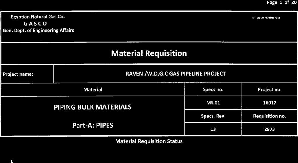
104
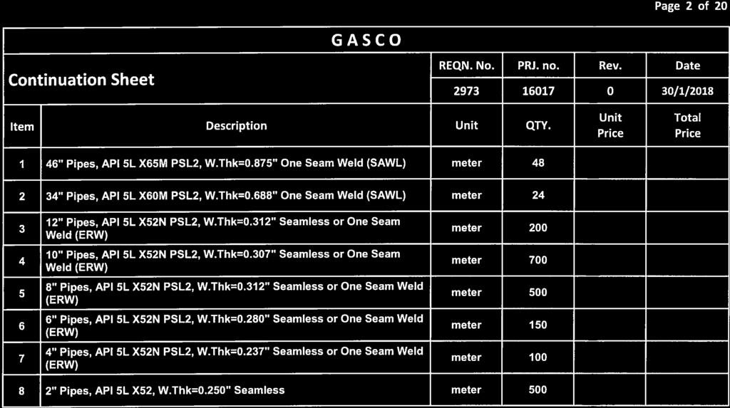
105
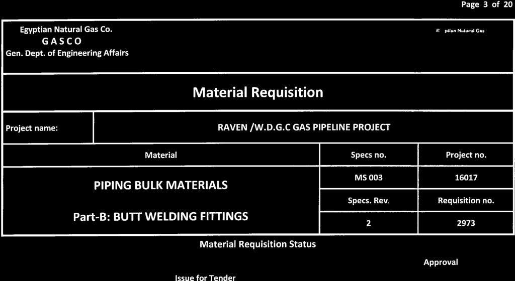
106
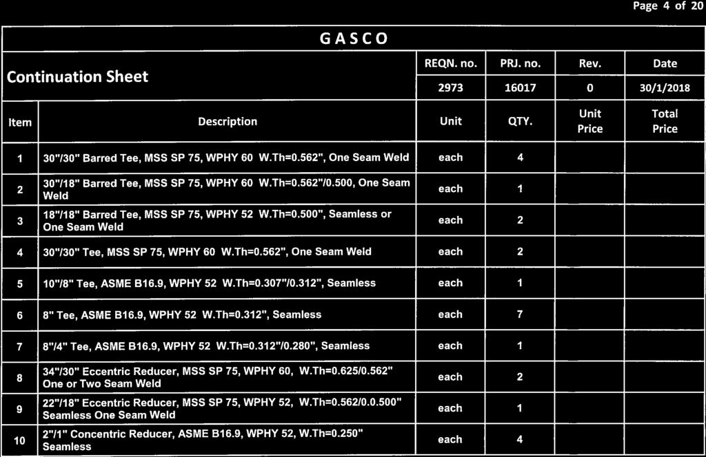
107
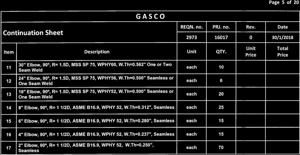
108
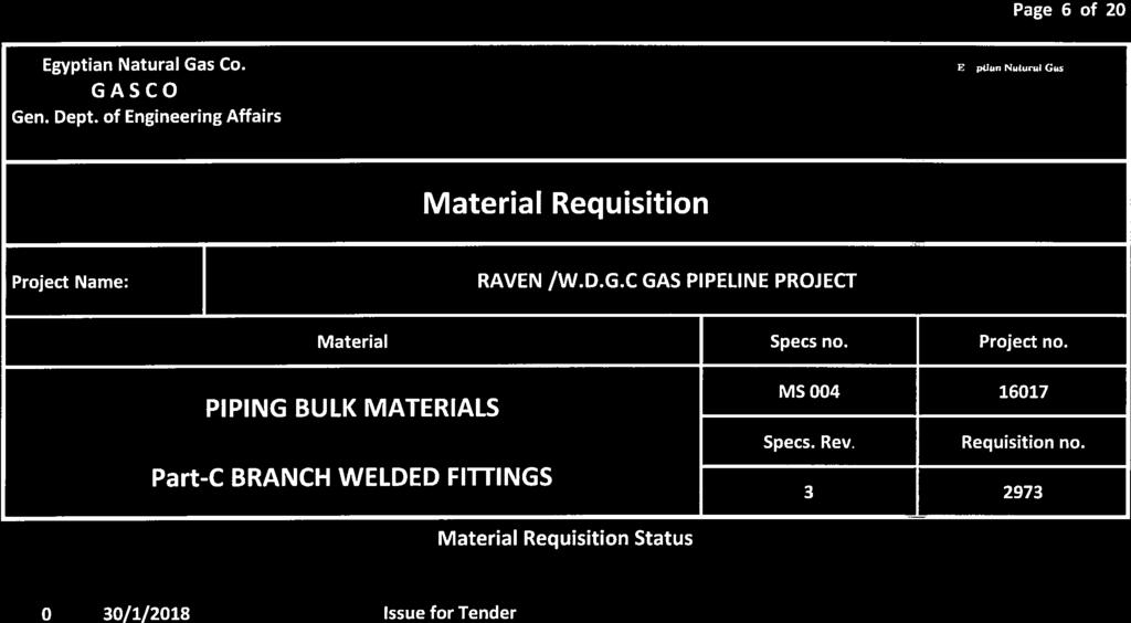
109
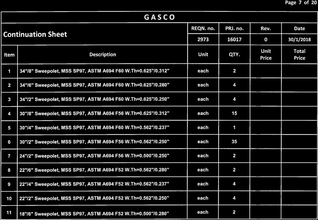
110
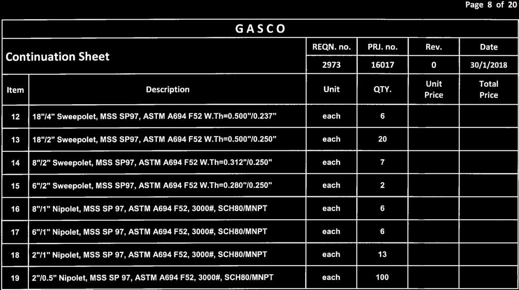
111
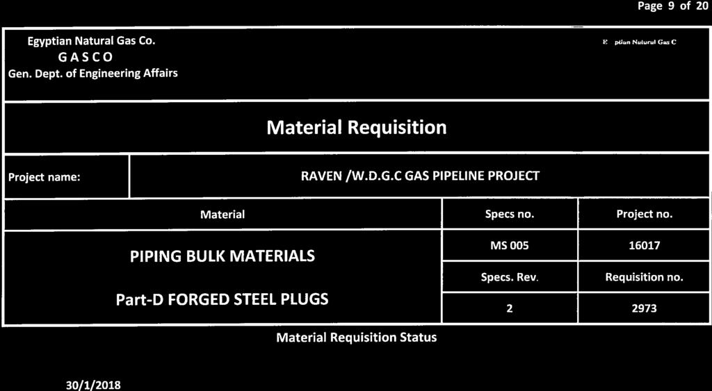
112
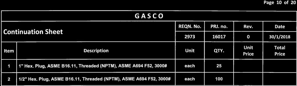
113
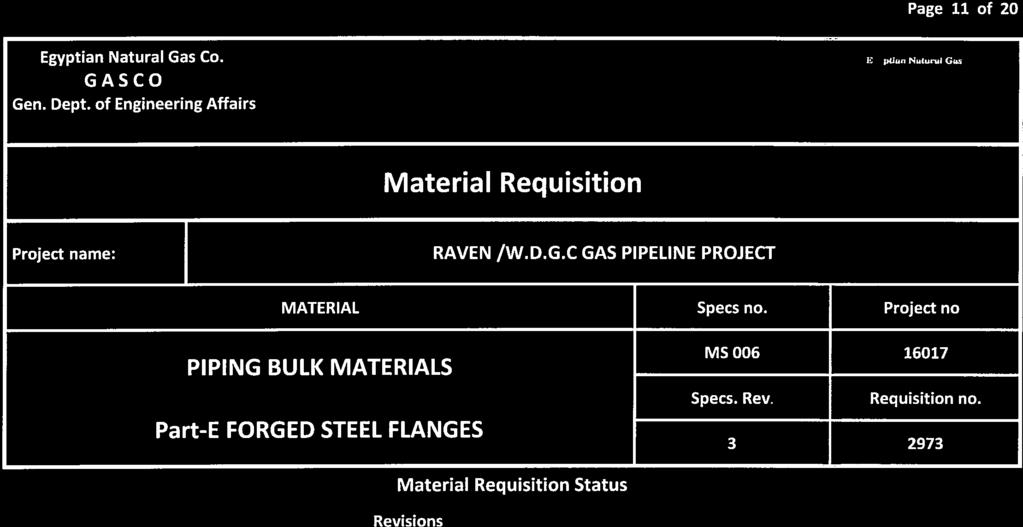
114
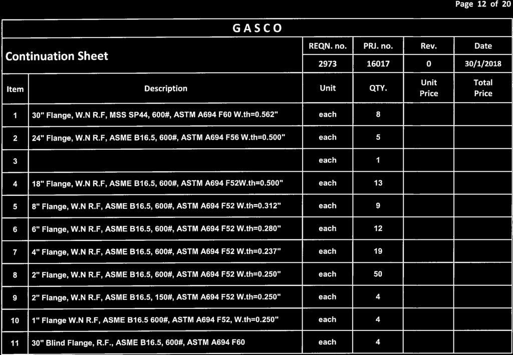
115
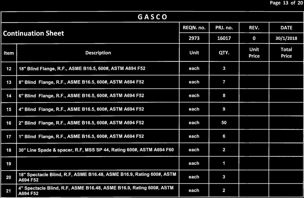
116
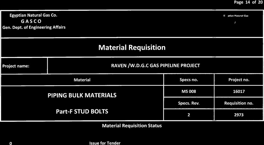
117
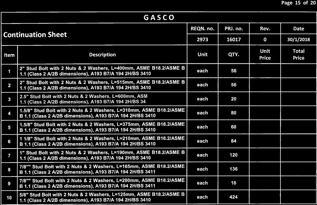
118
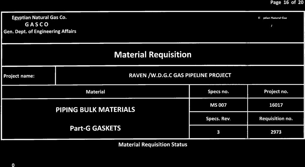
119
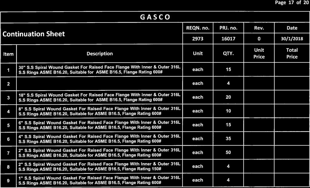
120
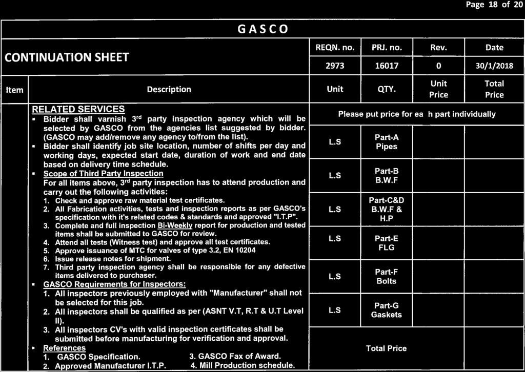
121
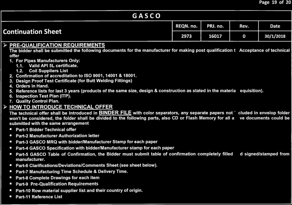
122
123
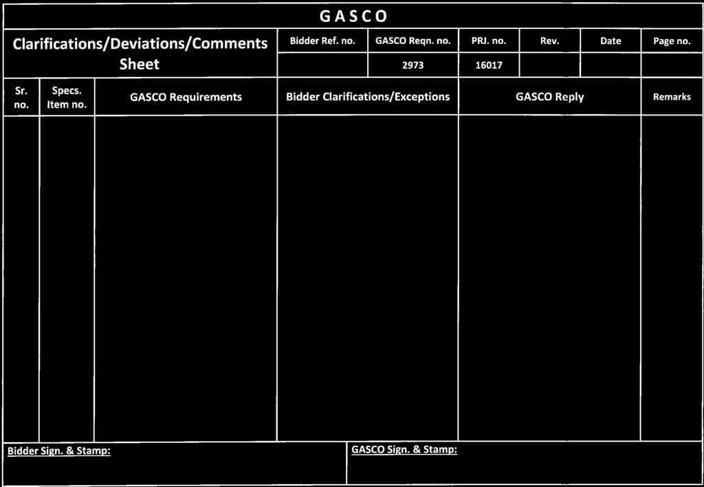
124
125 GENERAL SPECIFICATION FOR PIGS General Specification for Pigs Specs. No. / MS / 026 Rev. 5 Issue: 2009 No. of Sheets: 2
126 Pigs Specs. No. / MS / 026 Rev.-5 TECHNICAL SPECIFICATIONS FOR PIGS All pigs shall be suitable for high pressure natural gas pipeline (max. working pressure=70 bar) 1. High Density Foam Pig: Criss cross high density foam pig 8-10 lb /cu ft. can negotiate pipeline inner diameters & traverse bends down to 1.5 D radius safely. 2. Medium Density foam Pigs: Scarlet criss cross medium density foam pigs 5-7 lb/cu ft. with p.u coating for wipping pipeline. The pig can negotiate pipeline inner diameters & traverse bends down to 1.5 D radius safely. 3. Low Density Foam Pig: Criss cross low density foam pig 2-4 lb /cu ft. can negotiate pipeline inner diameters & traverse bends down to 1.5 D radius safely. 4. Cleaning Pigs: Cleaning pig of short body design which allows negotiation of bends down to 1.5D radius. The pig can negotiate pipeline inner diameters & traverse bends down to 1.5 D radius safely. Brushes to be Nylon brushes. The pig shall has: a- Minimum two polyurethane cups of high wear and abrasion resistance and of long lipped design to ensure efficient sealing. b- Polyurethane protector nose. All carbon steel body components shall have two coats of chemical resistant anticorrosive paint.. 5. Gauging Pigs: Gauging big shall be of two polyurethane driving cups and protector nose. The pig shall be fitted with aluminum gauging plate of diameter equal to 95% of the minimum internal diameter of the pipeline. The pig can negotiate pipeline inner diameters & traverse bends down to 1.5 D radius safely. All carbon steel body components shall have two coats of chemical resistant anticorrosive paint.. Page 1 of 2
127 Pigs Specs. No. / MS / 026 Rev Bi-Directional Pigs: The pig shall have polyurethane sealing discs, Polyurethane guiding, disc polyurethane protector noses and towing eye at each end to facilitate removal. The construction of the pig shall be of such that discs will not tear away from body. The pig can negotiate pipeline inner diameters & traverse bends down to 1.5 D radius safely. All carbon steel body components shall have two coats of chemical resistant anticorrosive paint RealSeal Cup Pig 4 cups, Heavy duty cups ULTRA Multi-lip discs - Multiple lip design (plain cup not accepted). - Capable of sealing upstream and downstream girth weld. - Capable of traveling long distances. Page 2 of 2
128 GENERAL SPECIFICATION FOR PIG SIGNALLERS General Specification for Pig Signalers Specs. No. / MS / 014 Rev. 5 Issue Nov No. of Sheets 2
129 Pig Signalers Specs. No. / MS / 014 Rev.-5 SPECIFICATIONS OF PIG SIGNALLER Manual reset visual pig signaler with a flag for use in natural gas pipelines. The signaler should be equipped with a ball valve so that the signaler can be removed for maintenance while the line is under pressure. 1. Detailed drawings and catalogues should be submitted with the offer. 2. The manufacturer shall confirm that the signaler should be equipped with a ball valve of fully welded construction body. 3. The manufacturer shall confirm that the signaler can be removed for maintenance while line is under pressure. 4. The manufacturer shall confirm that the signaler welding end material should be suitable for welding with API 5L line pipes. 5. Painting to be according to the attached spec. Page 1 of 2
130 Pig Signalers Specs. No. / MS / 014 Rev.-5 SPEC. 1 Painting PAINTING SPECIFICATION FOR PIG SIGNALLERS CARBON STEEL BODY COMPONENTS Paint cycle shall be as follows: Surface preparation: sa 3. 1 st Layer : Zinc Epoxy, 1 coat DFT 75 µm. 5 2 nd Layer : High Built (HB) Epoxy 200 µm. 3 rd Layer : Polyurethane (PU) 50 µm. Total DFT Final Color : 325 µm. : RAL 7035 Light Gray Page 2 of 2
131 GENERAL SPECIFICATION FOR QUICK RELEASE CLOSURES General Specification for Pig Trap Closures Specs. No. / MS / 013 Rev. 4 Issue: Nov No. of Sheets: 2
132 Closure Specs. No. / MS / 013 Rev.-4 QUICK RELEASE CLOSURES 1. Quick release closures are to be designed and manufactured to enable one operator using standard hand tools to open or close the unit within a reasonable period of time. 2. The closure unit shall include for primary and secondary safety features which will prevent the closure from being opened whilst under unacceptable internal pressures. The design of the closure and safety mechanism shall be in accordance with ASME VIII Division 1 UG 35. Detailed drawings of safety mechanisms to be supplied. 3. The general design philosophy of the closure shall be consistent with ASME B31.8. The manufacturer shall provide design details to demonstrate compliance with the code for the service conditions specified. 4. Where stresses in the closure cannot be adequately demonstrated by calculation in accordance with ANSI VIII - Division 1, then design can be verified by the use of suitable techniques such as finite element analysis (FEA) coupled with confirmatory strain gauge tests or proof testing in accordance with the pressure vessel code. The manufacturer to provide adequate documentary proof of the test method adopted, with the tender. 5. The closure will be supplied to the pressure rating specified and weld-end material thickness. All materials both body and seal to be suitable for service temperatures from -20 o C to 70 o C. The manufacturers to state the necessary heat treatment required to match the stated barrel material. The Closure Neck shall be a forging; castings are not permitted. The closure door may be a forging or machined from plate material which will meet the requirement of the relevant pressure vessel code; castings are not permitted. 6. Materials shall be to ASTM 694-F65 for X65 pipeline material ASTM 694-F60 for X60 pipeline material ASTM694 F56 for X56 pipeline material ASTM694 F52 for X52 pipeline material. 7. Closures to be hydro-statically tested to 1.5 x Design Pressure. 8. Physical/Chemical test certificates to be supplied to BS EN : 1991 (3.1 B) and be issued for all internal metallic pressure retaining parts and to also include for Impact and Hardness testing Ultrasonic examination shall be to ASME A388 with acceptance levels to ASME VIII Div. 2 para. AM (c) to (f) on blank forging. 9. MPI required on weld end preparation with hub end bevelled to ANSI to match stated barrel weld end dimensions. 10. Painting to be according to the attached spec. Page 1 of 2
133 Closure Specs. No. / MS / 013 Rev.-4 SPEC. 1 Painting PAINTING SPECIFICATION FOR ABOVEGROUND FACILITIES * For pipes, valves, bends and other fittings. Paint cycle shall be as follows: Surface preparation : sa st Layer : Zinc Epoxy, 1 coat DFT 75 µm. 2 nd Layer : High Built (HB) Epoxy 200 µm. 3 rd Layer : Polyurethane (PU) 50 µm. Total DFT Final Color : 325 µm. : RAL 7035 Light Gray Page 2 of 2
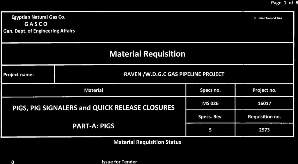
134
135
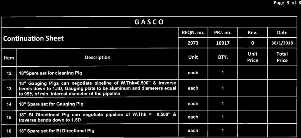
136

137
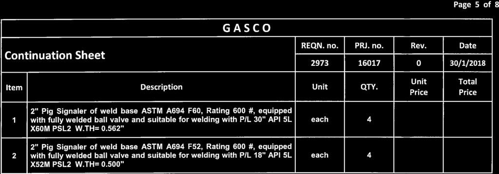
138
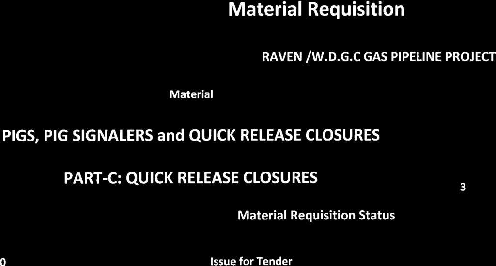

139
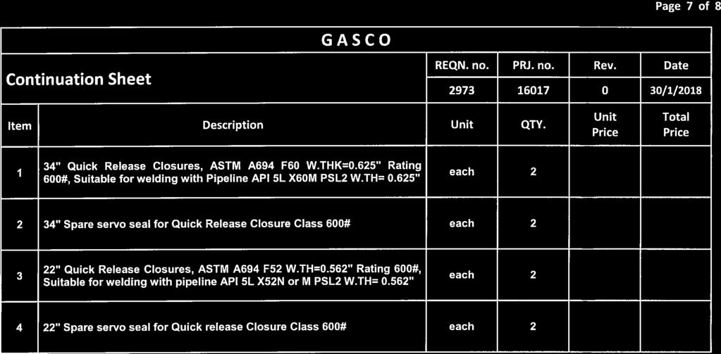
140
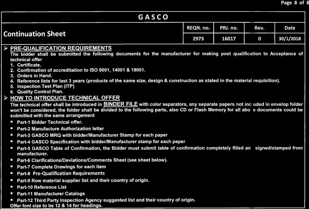
141
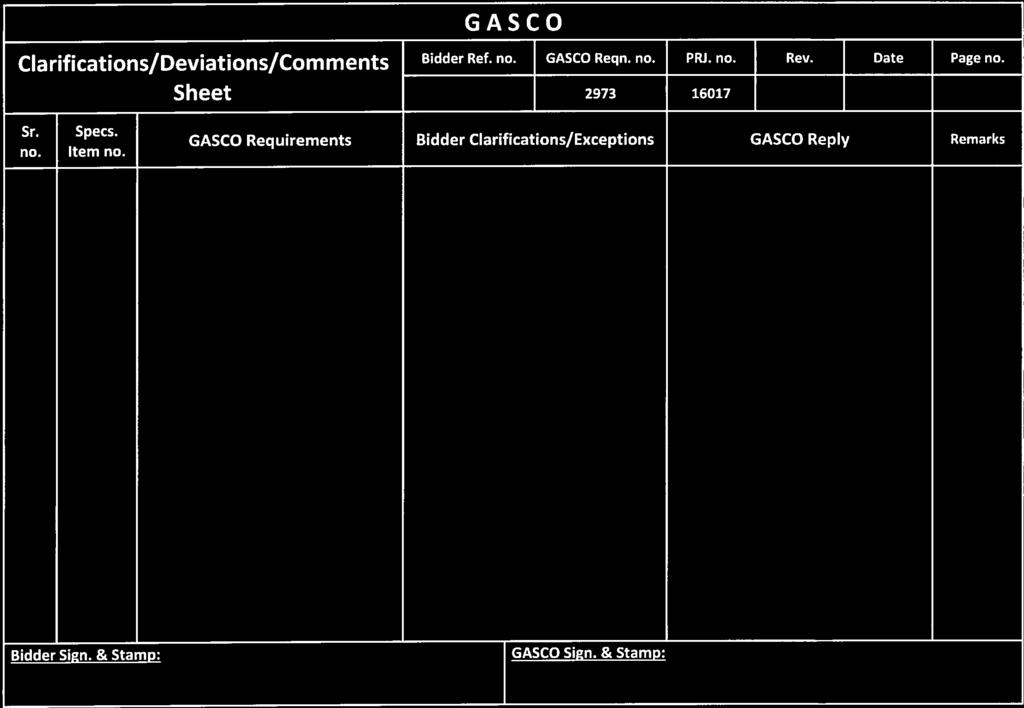
142
143 GENERAL SPECIFICATION FOR INSULATING JOINTS Specification For Insulating Joints MS / April 2008 Additional items: (2.9) & Pipe-pups U.T inspection item (4) 3 2 April 2005 Verification in welds inspection (item 4) 4 1 May Spec. Revisions Date verification No. of Sheets
144 Insulating Joint Specs. No. / MS / Rev.-3 SPECIFICATION FOR HIGH PRESSURE MONOBLOC INSULATING JOINTS 1- Scope: This specification covers the technical requirements for design, manufacture, testing and acceptance of monoblock insulating joints suitable for pipelines conveying GAS operating temperatures of 90 C. 2- Basic Requirements: 2.1 For size and grade of pipe steel of pipeline, see the attached table. 2.2 All insulating joints shall be prepared for welding to the pipelines. 2.3 The design pressure shall be the same as determined for the pressure class in which the insulating joint will be installed, this is specified in the attached table. The hydraulic test pressure shall be at least 1.5 times the design pressure. The manufacturer is responsible for the design and for the ability of the assembly to withstand design and hydraulic test pressures. 2.4 The design of the insulating joint shall be such that:- The electrical resistance does not decrease with time. The insulating material does not creep. The conveyed fluid does not permeate with time into the structure of the joint creating over-pressure problems. 2.5 The manufacturer shall submit for purchaser a detailed construction drawing of the proposed joint, data sheet containing the guaranteed mechanical and electrical properties of each of the insulating materials (spacer, gasket, filler, coating, lining) intended for use and the design calculations for the joint. 2.6 Calculations shall be carried out by approved stress analysis method or according to ASME code sec. Viii-Division 1 Appendix 2, adequately adapted. 2.7 Electrical Resistance minimum 5 M ohm. At 1000 V.D.C. 2.8 Dielectric strength minimum 3 K.V. x 1 min (50 Hz). 2.9 The joints must have a cable lug (40 x 50 x 5mm) with 10 mm hole (one per each pipe-pup). Page 1 of 3
145 Insulating Joint Specs. No. / MS / Rev Protection: 3.1 Both internal and external surfaces of the finished joint shall be blasted in order to reach as a minimum as cleanliness degree of sa. 2.1/2. In accordance with SIS The internal surface of the joint shall be lined with epoxy - resin at least 400 micrometers D.F.T. 3.3 The external surface shall be provided with a two - pack solventless 400 micrometers - at least - D.F.T. epoxy. 3.4 Both coating and lining shall end approximately 40 mm from each end to be butt welded. 4- Acceptance testing: The acceptance testing shall be carried out on all joints this testing includes:- Welds inspection by ( R.T, U.T & M.P.I) as follows:- Butt welds (BW) to be tested by R.T and U.T Closure welds (CW) to be tested by U.T. Seal welds (SW) to be tested by U.T and/or M.P.I Pipe-pups to be U.T inspected. Hydrostatic test Fatigue hydrostatic test Dielectric strength test Final visual inspection Check of bevels and taperings. Check of joint over all dimensions. 5- Testing Documents: The Manufacturer shall supply the purchaser, at times and ways foreseen in the purchasing order, with the certificates relevant to: Verifications, checks and tests included in the inspection data sheet "I.D.S." Last revision of the construction drawing. Summary of the employed materials. Upsetting of the marking. Should the delivery of the above mentioned documents not occur or be incomplete, the purchaser will consider the supply of the joints incomplete. Page 2 of 3
146 Insulating Joint Specs. No. / MS / Rev Technical and commercial offers: Minimum 3 complete copies from technical and commercial offers must be enclosed with typical product brochure and 4 copies from testing documents. 7- Packing: All joints shall be adequately packed to prevent damages in transit by ship and by road over rough terrain, according to packing specification. In particular, the ends of the pups shall be fitted with wood or plastic cups, and the welding bevels shall be carefully protected and cleaned off. Page 3 of 3
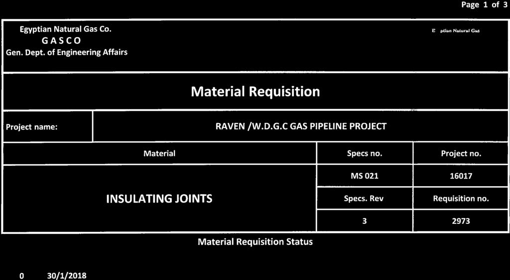
147
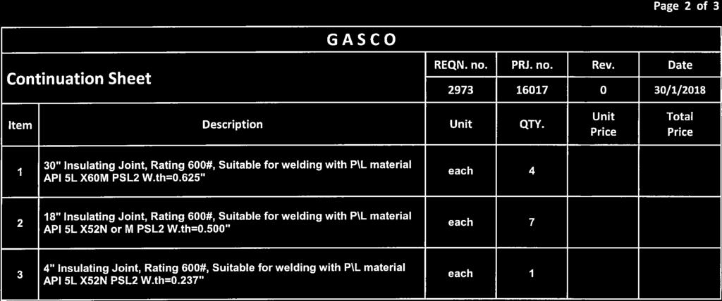
148
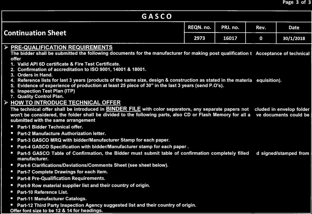
149
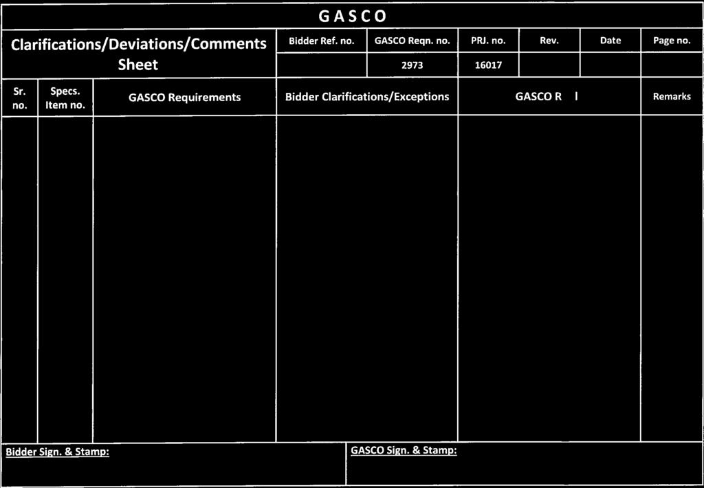
150
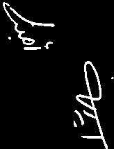
151
152
153
154
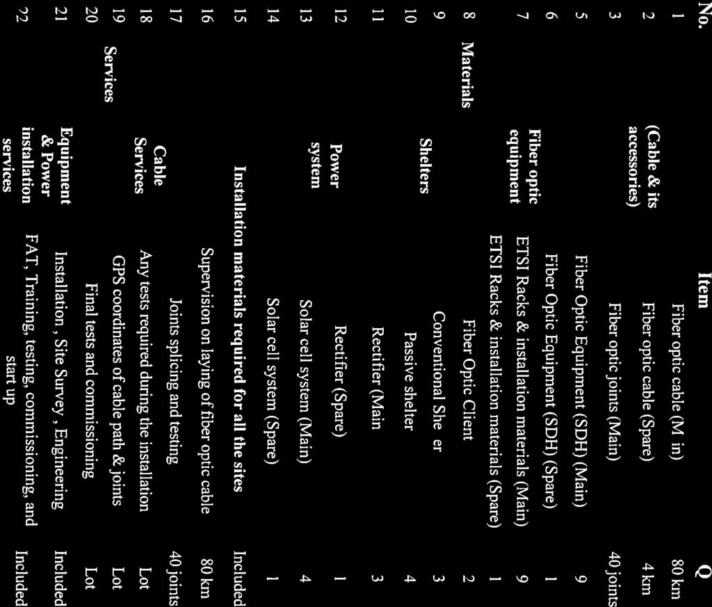

155
156

157
158
159
160
161


162
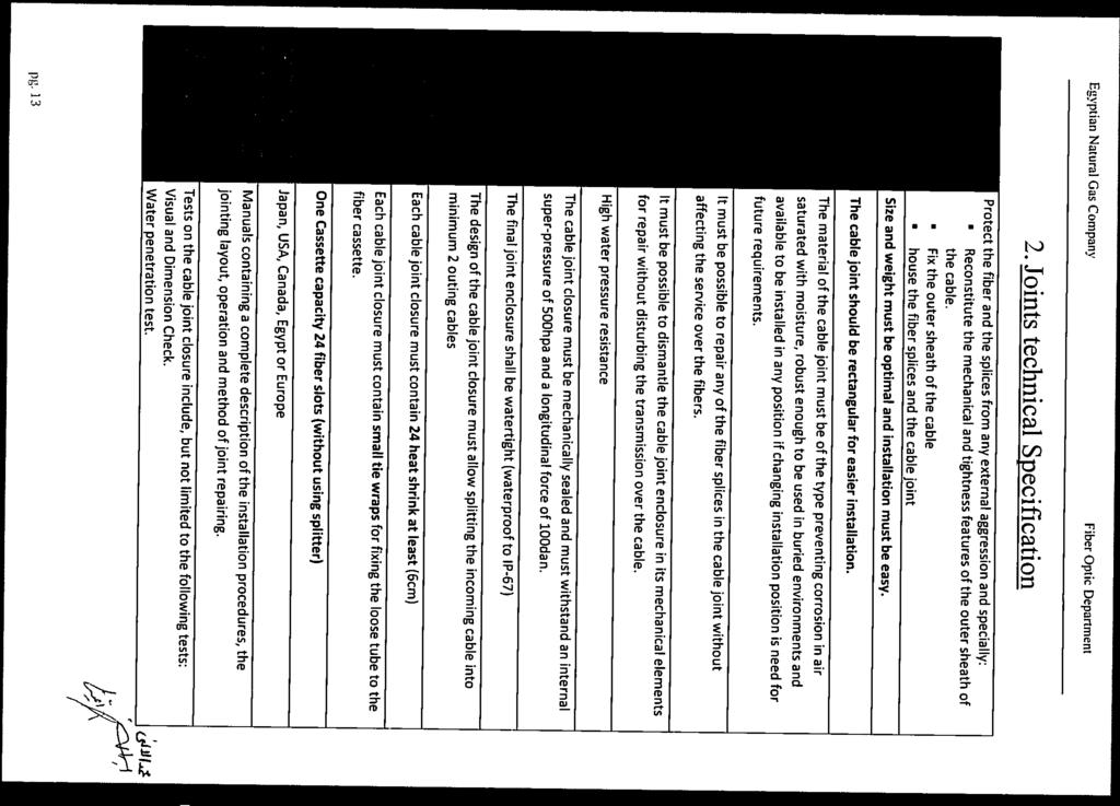
163
164

165
166
167
168
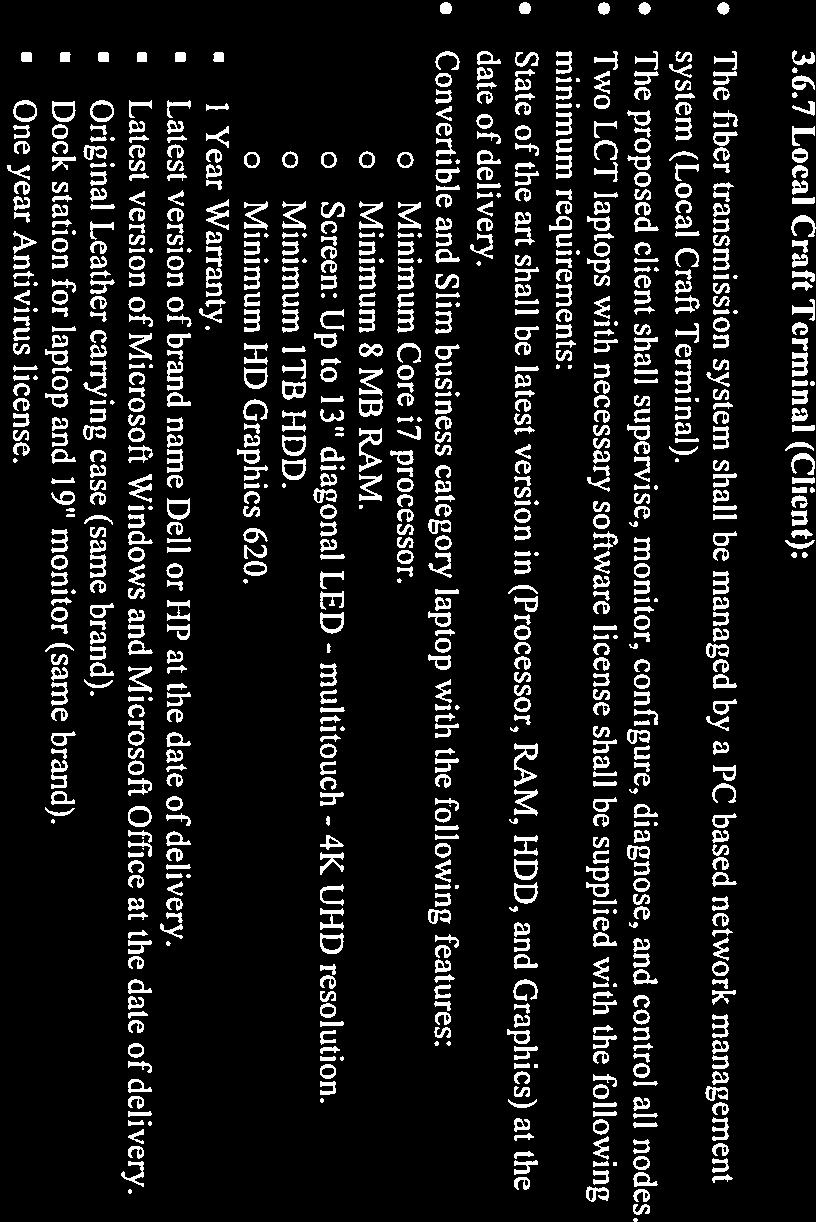
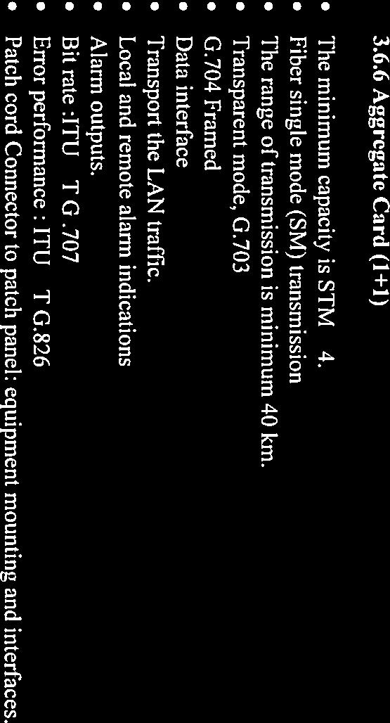
169
170

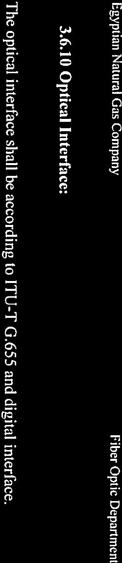


171
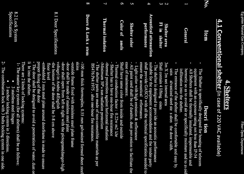
172
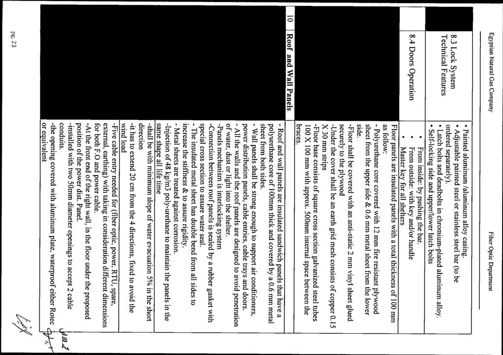
173
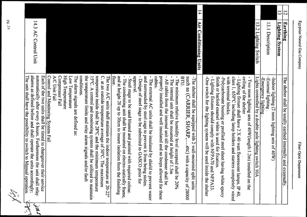
174
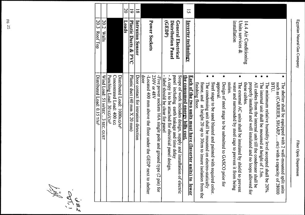
175

176
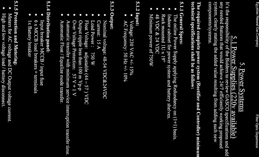

177
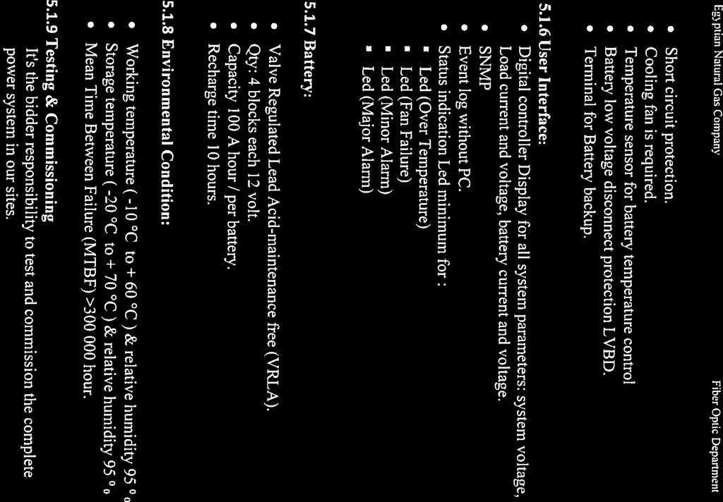
178
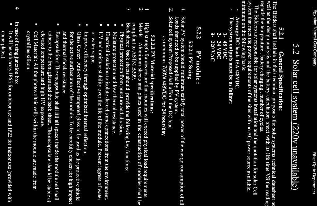
179
180

181
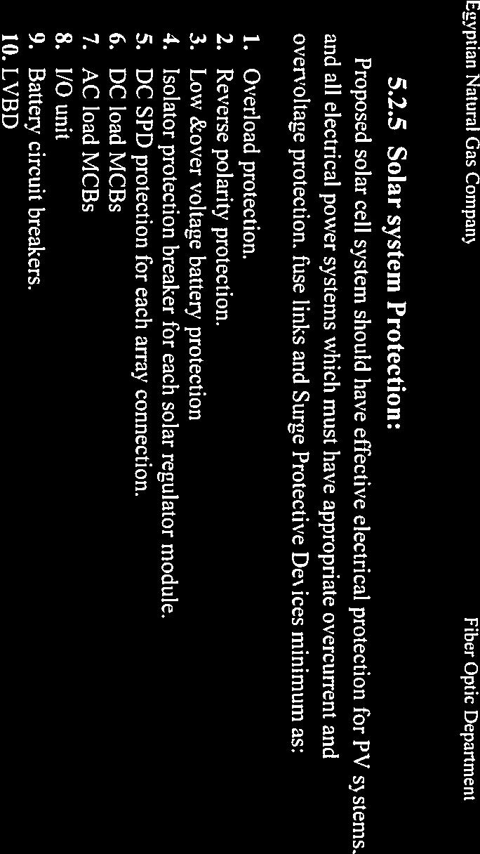
182
183
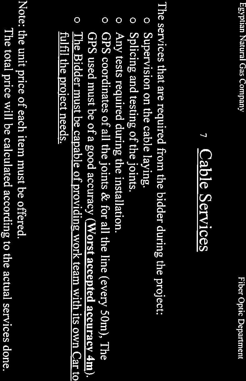
184
185
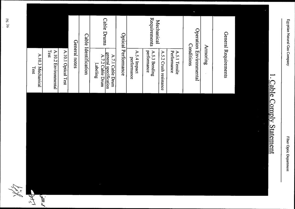
186
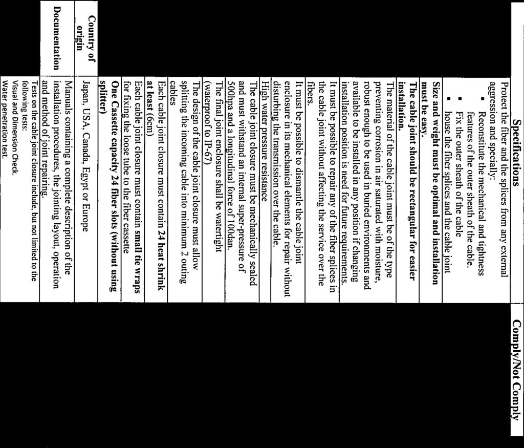
187
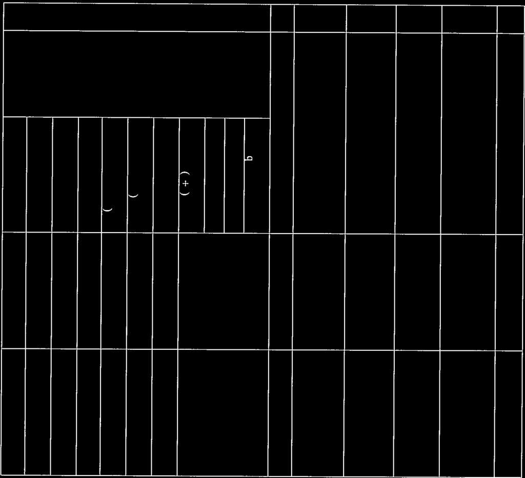
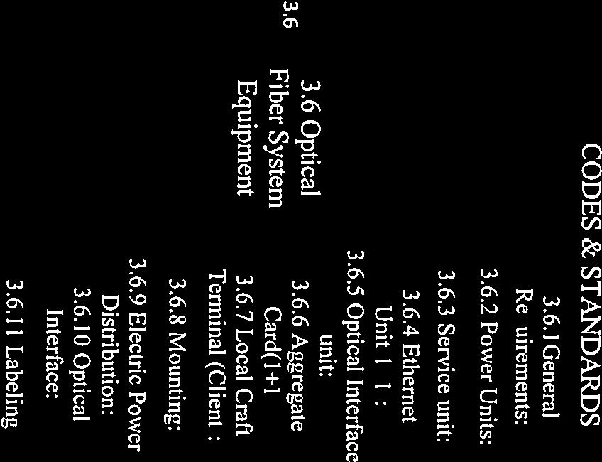
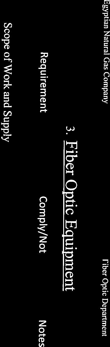

188
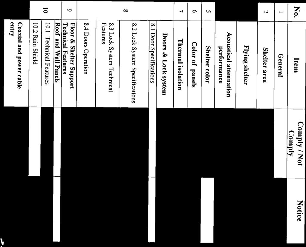
189

190
191
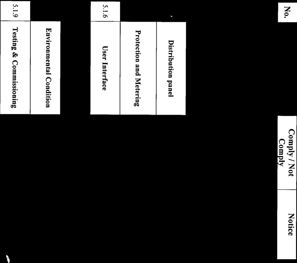
192

193

194
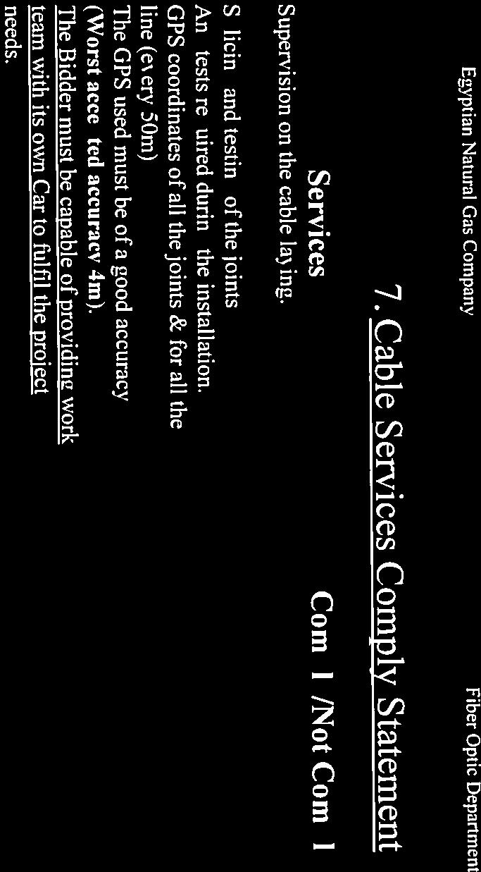
195
BUREAU OF INDIAN STANDARDS Draft Indian Standard
 For Comments Only BUREAU OF INDIAN STANDARDS Draft Indian Standard STEEL PLATES FOR PRESSURE VESSEL FOR INTERMEDIATE AND HIGH TEMPERATURE SERVICE INCLUDING BOILERS (Third Revision of IS 2002) ICS 77.140.30
BS EN Welded steel tubes for pressure purposes Technical delivery conditions Non alloy steel tubes with specified room temperature properties
 BS EN 10217 1. Welded steel tubes for pressure purposes Technical delivery conditions Non alloy steel tubes with specified room temperature properties 1 SCOPE This Part of EN 10217 specifies the technical
TMK HYDRA ART INSIDE SKIVED AND ROLLER BURNISHED COLD FINISHED SEAMLESS STEEL TUBES and PISTON RODS TUBES FOR HYDRAULIC CYLINDERS
 TMK HYDRA ART INSIDE SKIVED AND ROLLER BURNISHED COLD FINISHED SEAMLESS STEEL TUBES and PISTON RODS TUBES FOR HYDRAULIC CYLINDERS TMK is one of the world s leading producers of tubular products for the
BS EN Hollow bars for machining Technical delivery conditions Non alloy and alloy steels
 BS EN 10294 1. Hollow bars for machining Technical delivery conditions Non alloy and alloy steels 1 Scope This part of EN 10294 specifies the technical delivery conditions for seamless steel hollow bars
ASTM A420-Standard Specification for Piping Fittings of Wrought Carbon Steel and Alloy Steel for Low-Temperature Service
 ASTM A420-Standard Specification for Piping Fittings of Wrought Carbon Steel and Alloy Steel for Low-Temperature Service 1. Scope 1.1 This specification 2 covers wrought carbon steel and alloy steel fittings
API5L 45th Edition Specification for Line Pipe Scope. Delivery Condition. Ordering Information. Typical process of manufacturing
 API5L 45th Edition Specification for Line Pipe Scope Specified the manufacture of two product levels (PSL1 and PSL2) of seamless and welded steel pipe for the use of a pipeline in the transportation of
Gas Industry Standard
 Gas Industry Standard GIS/L2:2006 Specification for Steel pipe 21.3 mm to 1 219 mm outside diameter for operating pressures up to 7 bar (supplementary to BS EN 10208-1) Contents Foreword Mandatory and
METALLIC MATERIAL SPECIFICATION
 1. Scope: Page: 1 of 5 1.1. This specification shall be utilized in procurement of AISI 8630 modified steel (UNS G86300) in quenched and tempered condition to 22 HRc maximum hardness. 1.2. These materials
XI'AN LINKUN STEEL PIPE CO., LTD
 Designation: A 50 0 (Reapproved 2005) Standard Specification for Hot-Formed Welded and Seamless Carbon Steel Structural Tubing This standard is issued under the fixed designation A 50; the number immediately
AMENDMENTS TO OPSS 1802 (JAN 95) MATERIAL SPECIFICATION FOR SMOOTH WALLED STEEL PIPE SUPPLY, STORAGE, AND DELIVERY OF WELDED STEEL PIPE
 MATERIAL SPECIFICATION FOR SMOOTH WALLED STEEL PIPE SUPPLY, STORAGE, AND DELIVERY OF WELDED STEEL PIPE") Works and Emergency Services CITY OF TORONTO WATER AND WASTEWATER SERVICES STANDARD CONSTRUCTION SPECIFICATIONS TS 1802 June 2001 AMENDMENTS TO OPSS 1802 (JAN 95) MATERIAL SPECIFICATION FOR SMOOTH WALLED
Works and Emergency Services CITY OF TORONTO WATER AND WASTEWATER SERVICES STANDARD CONSTRUCTION SPECIFICATIONS TS 1802 June 2001 AMENDMENTS TO OPSS 1802 (JAN 95) MATERIAL SPECIFICATION FOR SMOOTH WALLED
HOT ROLLED STEEL FLAT PRODUCTS FOR STRUCTURAL FORMING AND FLANGING PURPOSES SPECIFICATION (Third Revision of IS 5986)
") For Comments Only Draft Indian Standard Doc: MTD 4(4939) HOT ROLLED STEEL FLAT PRODUCTS FOR STRUCTURAL FORMING AND FLANGING PURPOSES SPECIFICATION (Third Revision of IS 5986) ICS 77.140.50 Not to be reproduced
For Comments Only Draft Indian Standard Doc: MTD 4(4939) HOT ROLLED STEEL FLAT PRODUCTS FOR STRUCTURAL FORMING AND FLANGING PURPOSES SPECIFICATION (Third Revision of IS 5986) ICS 77.140.50 Not to be reproduced
PART UF REQUIREMENTS FOR PRESSURE VESSELS FABRICATED BY FORGINGS
 p 1 of 6 UF-1 UF-12 PART UF REQUIREMENTS FOR PRESSURE VESSELS FABRICATED BY FORGING the test temperature be higher than 20 F ( 29 C). Certification is required. An ultrasonic examination shall be made
Standard Specification for Seamless Cold-Drawn Carbon Steel Feedwater Heater Tubes 1
 Designation: A 556/A 556M 96 (Reapproved 2005) www.tubingchina.com Standard Specification for Seamless Cold-Drawn Carbon Steel Feedwater Heater Tubes 1 This standard is issued under the fixed designation
DNVGL-CP-0347 Edition May 2016
 CLASS PROGRAMME Approval of manufacturers DNVGL-CP-0347 Edition May 2016 The content of this service document is the subject of intellectual property rights reserved by ("DNV GL"). The user accepts that
Specification for the Fabrication of Structural Steel Pipe API SPECIFICATION 2B SIXTH EDITION, JULY 2001 EFFECTIVE DATE: JANUARY 1, 2002
 Specification for the Fabrication of Structural Steel Pipe API SPECIFICATION 2B SIXTH EDITION, JULY 2001 EFFECTIVE DATE: JANUARY 1, 2002 Specification for the Fabrication of Structural Steel Pipe Upstream
ADDENDUM 3. Replace all of Annex N with the attached.
 Date of Issue: July 20, Effective date: January 1, 2012 Affected Publication: API Specification 5L/ISO 3183, Specification for Line Pipe, 44th Edition, October 2007 ADDENDUM 3 Replace all of Annex N with
IMPACT. Chemical composition For the chemical composition of the ladle analysis the following limits are applicable (in %):
:") IMPACT Wear resistant steel Material data sheet, edition April 2016 1 DILLIDUR IMPACT is a wear resistant steel with a nominal hardness of 340 HBW in delivery condition. DILLIDUR IMPACT is not a constructional
IMPACT Wear resistant steel Material data sheet, edition April 2016 1 DILLIDUR IMPACT is a wear resistant steel with a nominal hardness of 340 HBW in delivery condition. DILLIDUR IMPACT is not a constructional
Pre-Audit Application Form
 Please provide the following information and return responses to AASHTO. Provide all applicable supporting documentation requested. Mill Name: Physical Address: Mailing Address: (if different from above)
EAM :2003/05 Revision 01 21/10/2016
 European Approval for Materials Data Sheet EAM-0879-04 This data sheet has been raised in accordance with the requirements of Article 15 of the Pressure Equipment Directive 2014/68/EU. The material described
Structural Steel Plate and Strip to EN 10025
 Data sheet: A3.7 Structural Steel Plate and Strip to EN 10025 General description ArcelorMittal South Africa produces and markets hot rolled structural steel plate and coil to EN 10025 in the following
Anchor chain cables and accessories including chafing chain for emergency towing arrangements
 (1988) (Rev 1 1997) (Rev. 2 July 1999) (Rev.3 July 2002) (Rev.4 July 2003) (Rev.5 May 2004) Anchor chain cables and accessories including chafing chain for emergency towing arrangements.1 General requirements
Section 906. STRUCTURAL STEEL
 906.01 Section 906. STRUCTURAL STEEL 906.01. General Requirements. Finished rolled shapes must be free from imperfections that affect strength and durability in accordance with ASTM A 6. Rolled shapes
Standard Specification for Welded and Seamless Steel Pipe Piles 1
 Designation: A 252 98 e1 An American National Standard Standard Specification for Welded and Seamless Steel Pipe Piles 1 This standard is issued under the fixed designation A 252; the number immediately
Cast Steel Propellers W27. (May 2000) (Rev.1 May 2004)
 (Rev.1 May 2004)") (May 2000) (Rev.1 May 2004) Cast Steel Propellers 1. Scope 1.1 These unified requirements are applicable to the manufacture of cast steel propellers, blades and bosses. 1.2 Where the use of alternative
(May 2000) (Rev.1 May 2004) Cast Steel Propellers 1. Scope 1.1 These unified requirements are applicable to the manufacture of cast steel propellers, blades and bosses. 1.2 Where the use of alternative
Specification for Pipe Fittings
 Specification for Pipe Fittings Specification for Pipe Fittings Page 1 of 11 Table of Contents 1.0 SCOPE...3 2.0 DEFINITIONS...3 3.0 REFERENCES, CODES AND STANDARDS...3 4.0 CONTRACTOR'S RESPONSIBILITIES...4
High strength fine grained structural steel. Quenched and tempered. Product description. 890 a product brand of Dillinger 1/6
 890 High strength fine grained structural steel Quenched and tempered Material data sheet, edition April 2016 1 DILLIMAX 890 is a high strength quenched and tempered, fine grained structural steel with
High strength fine grained structural steel. Quenched and tempered. Product description. 965 a product brand of Dillinger 1/6
 965 High strength fine grained structural steel Quenched and tempered Material data sheet, edition April 2016 1 DILLIMAX 965 is a high strength quenched and tempered, fine grained structural steel with
2. TEST RECORDS: All records of tests and analysis shall be kept in suitable forms approved by the Bureau.
 SCHEME OF TESTING AND INSPECTION FOR CERTIFICATION OF CARBON STEEL BILLETS, BLOOMS, SLABS AND BARS FOR FORGINGS ACCORDING TO IS:1875-1992 (Fifth Revision) 1. LABORATORY: A laboratory shall be maintained
Materials and Qualification Procedures for Ships
 Materials and Qualification Procedures for Ships Approval of a Works for the Manufacture of Non-heat treated ERW Steel Pipes Revision 2, Sept 2014 Lloyd s Register Group Limited, its subsidiaries and affiliates
REVISION CONTROL SHEET DOCUMENT TYPE : TECHNICAL SPECIFICATION TITLE : TECHNICAL SPECIFICATION FOR AUSTENITIC STAINLESS STEEL PIPES
 REVISION CONTROL SHEET DOCUMENT TYPE : TECHNICAL SPECIFICATION NO. : PC-M-308 TITLE : AUSTENITIC STAINLESS STEEL PIPES REV. NO. & DATE DESCRIPTION OF REVISION PREPARED BY CHECKED BY REVIEWED BY APPROVED
XI'AN LINKUN STEEL PIPE CO., LTD
 Designation: A 334/A 334M 04a Standard Specification for Seamless and Welded Carbon and Alloy-Steel Tubes for Low-Temperature Service 1 This standard is issued under the fixed designation A 334/A 334M;
Standard Specification for Seamless and Welded Carbon and Alloy-Steel Tubes for Low-Temperature Service 1
 Designation: A 334/A 334M 04a Standard Specification for Seamless and Welded Carbon and Alloy-Steel Tubes for Low-Temperature Service 1 This standard is issued under the fixed designation A 334/A 334M;
Chemical composition For the ladle analysis, the following limiting values in % are applicable: C Si Mn P S
 500 Wear resistant steel Material data sheet, edition April 2016 1 DILLIDUR 500 is a wear resistant steel with a nominal hardness of 500 HBW in delivery condition ex works. DILLIDUR 500 is preferentially
Specifications of Impeller forgings. Quantity: 2 No s. (Please find the attachment for material specification HY19391)
") Specifications of Impeller forgings Material Specification: HY19391 Grade: V X12 Cr13 G Dimensions: OD 830 X ID 370 X Thickness 120 (all are in mm) Quantity: 2 No s. (Please find the attachment for material
Specifications of Impeller forgings Material Specification: HY19391 Grade: V X12 Cr13 G Dimensions: OD 830 X ID 370 X Thickness 120 (all are in mm) Quantity: 2 No s. (Please find the attachment for material
Standard Specification for Electric-Fusion (Arc)-Welded Steel Pipe (NPS 4 and Over) 1
-Welded Steel Pipe (NPS 4 and Over) 1") Designation: A 39/A 39M 04 Standard Specification for Electric-Fusion (Arc)-Welded Steel Pipe (NPS 4 and Over) This standard is issued under the fixed designation A 39/A 39M; the number immediately following
Designation: A 39/A 39M 04 Standard Specification for Electric-Fusion (Arc)-Welded Steel Pipe (NPS 4 and Over) This standard is issued under the fixed designation A 39/A 39M; the number immediately following
Government Recognized Export House OHSAS 18001:2007 ISO 14001:2004 PED Approved Company.
 Government Recognized Export House OHSAS 18001:2007 ISO 14001:2004 PED Approved Company. Phone : +91 22 4343 1313 (25 Lines) Fax : +91 22 2389 4311 Email : sales@rolfalloy.com Designation: A 334/A 334M
Guidelines for the Construction of Pressure Vessel Type Tanks Intended for the Transportation of Anhydrous Ammonia at Ambient Temperatures
 (1992) (1992/Corr.) Guidelines for the Construction of Pressure Vessel Type Tanks Intended for the Transportation of Anhydrous Ammonia at Ambient Temperatures 1. Scope 1.1 These Guidelines complement the
Standard Specification for Seamless and Welded Ferritic and Martensitic Stainless Steel Tubing for General Service 1
 Designation: A 268/A 268M 0 An American National Standard Standard Specification for Seamless and Welded Ferritic and Martensitic Stainless Steel Tubing for General Service This standard is issued under
TECHNICAL REQUIREMENTS FOR PRECIPITATION HARDENING (SS 17-4 PH and PH 13-8 MO) STAINLESS STEEL BARS
 STAINLESS STEEL BARS") TECHNICAL REQUIREMENTS FOR PRECIPITATION HARDENING (SS 17-4 PH and PH 13-8 MO) STAINLESS STEEL BARS 1.0 SCOPE This Specification establishes the requirements for manufacture, inspection, testing and supply
TECHNICAL REQUIREMENTS FOR PRECIPITATION HARDENING (SS 17-4 PH and PH 13-8 MO) STAINLESS STEEL BARS 1.0 SCOPE This Specification establishes the requirements for manufacture, inspection, testing and supply
JIS G3456 Carbon Steel Pipes for High Temperature Service
 JIS G3456 Carbon Steel Pipes for High Temperature Service 1. Scope This Japanese Industrial Standard specifies the carbon steel pipes, hereinafter referred to as the "pipes", mainly used for piping at
RELIABLE STEEL DISTRIBUTORS
 . BS EN 10025 3 Hot rolled products of structural steels Technical delivery conditions for normalized/normalized rolled weldable fine grain structural steels 1 Scope Part 3 of this document, in addition
2. Test Records - All records of tests and analysis shall be kept in suitable forms approved by the Bureau.
 . Doc: STI/2041/ 2 SCHEME OF TESTING AND INPECTION FOR CERTIFICATION OF STEEL PLATES FOR PRESSURE VESSELS USED AT MODERATE AND LOW TEMPERATURE ACCORDING TO IS 2041:2009 (Third Revision) 1. Laboratory A
Standard Specification for Seamless and Welded Ferritic and Martensitic Stainless Steel Tubing for General Service
 SA-268/SA-268M ASME BPVC.II.A-2015 Standard Specification for Seamless and Welded Ferritic and Martensitic Stainless Steel Tubing for General Service 1. Scope 1.1 This specification covers a number of
TAM Plus is the new range of hot rolled mechanical tubes, designed by Tenaris to better meet the needs of industrial sector.
 TAM Plus TAM Plus Reference norm EN 10297-1 Seamless STEEL tubes with high machinability (HL) and close tolerances for mechanical applications TAM Plus is the new range of hot rolled mechanical tubes,
STANDARD SPECIFICATION FOR SUBMERGED ARC HELICAL WELDED (SAWH) LINE PIPE (ONSHORE)
 LINE PIPE (ONSHORE)") (ONSHORE) Page 1 of 35 FOR SUBMERGED ARC HELICAL WELDED (SAWH) LINE PIPE (ONSHORE) (ONSHORE) Page 2 of 35 Abbreviations: API ASTM BM CE CVN FBH HAZ ID KvL KvT MPQT MPS NOT OD/D SAWH SMAW t UT American
(ONSHORE) Page 1 of 35 FOR SUBMERGED ARC HELICAL WELDED (SAWH) LINE PIPE (ONSHORE) (ONSHORE) Page 2 of 35 Abbreviations: API ASTM BM CE CVN FBH HAZ ID KvL KvT MPQT MPS NOT OD/D SAWH SMAW t UT American
Standard Specification for Seamless and Welded Ferritic/Austenitic Stainless Steel Pipe
 SA-790/SA-790M ASME BPVC.II.A-2015 Standard Specification for Seamless and Welded Ferritic/Austenitic Stainless Steel Pipe 1. Scope 1.1 This specification covers seamless and straight-seam welded ferritic/austenitic
Standard Specification for Structural Steel for Ships 1
 Designation: Standard Specification for Structural Steel for Ships 1 This standard is issued under the fixed designation A 131/A 131M; the number immediately following the designation indicates the year
Aluminium Alloys for Hull Construction and Marine Structure
 (May 1998) (Rev.1 May 2004) (Rev.2 Dec 2004) (Rev.3 May 2006) (Rev.4 Dec 2011) (Rev.5 June 2014) Aluminium Alloys for Hull Construction and Marine Structure TABLE OF CONTENTS 1. Scope 2. Approval 3. Aluminium
CHAPTER 2. Steel and Iron Materials
 CHAPTER 2 Steel and Iron Materials BRS Rules, II -Part 1 Metallic Materials Chapter 2, Table of Contents Table of Contents Section 1 1. 2. 3. 4. 5. 6. 7. 8. 9. 10. Section 2 1. 2. 3. 4. 5. Steel Plates,
Hull and machinery steel forgings
 (1978) (Rev.1 1980) (Rev.2 July 2002) (Rev.3 May 2004) Hull and machinery steel forgings.1 Scope.1.1 These requirements are applicable to steel forgings intended for hull and machinery applications such
Weldable fine grained structural steel, thermomechanically rolled
 460 Weldable fine grained structural steel, thermomechanically rolled Material data sheet, edition September 2018 1 DI-MC 460 is a thermomechanically rolled, fine grained structural steel with minimum
SECTION REINFORCING STEEL
 SECTION REINFORCING STEEL 1. DESCRIPTION This specification shall govern the furnishing and placing of reinforcing steel, deformed and smooth, of the size and quantity designated on the plans and in accordance
SPECIFICATION FOR PRESSURE VESSEL PLATES, CARBON STEEL, FOR MODERATE- AND LOWER-TEMPERATURE SERVICE
 Technical Literature: ASME SA-516 [ASTM A516] Company Website: www.metalspiping.com SA-516/SA-516M Carbon & Low Alloy Steels From Hebei Metals Industrial Limited SPECIFICATION FOR PRESSURE VESSEL PLATES,
ANNEXURE-IA. Bid Security Amount : INR 5,00, OR USD 11, ( or equivalent Amount in any currency )
") ANNEXURE-IA Tender No& Date : SDG 1982 P09 DATED 29.01.2009 Tender Fee : INR 4500.00 OR USD 100.00 Bid Security Amount : INR 5,00,000.00 OR USD 11,000.00 ( or equivalent Amount in any currency ) Bidding
ANNEXURE-IA Tender No& Date : SDG 1982 P09 DATED 29.01.2009 Tender Fee : INR 4500.00 OR USD 100.00 Bid Security Amount : INR 5,00,000.00 OR USD 11,000.00 ( or equivalent Amount in any currency ) Bidding
MAHARASHTRA NATURAL GAS LIMITED
 Replies to Queries of the Bidders Date: 01.12.2018 SUB: Replies to queries of the bidders for Tender for Procurement of 6 & 4 Coated Line Pipe for Sindhudurg, Ramanagara & Pune area for CGD Projects of
CONSTRUCTION SPECIFICATION FOR STRUCTURAL STEEL
 ONTARIO PROVINCIAL STANDARD SPECIFICATION METRIC OPSS 906 FEBRUARY 1993 CONSTRUCTION SPECIFICATION FOR STRUCTURAL STEEL 906.01 SCOPE 906.02 REFERENCES 906.03 DEFINITIONS TABLE OF CONTENTS 906.04 SUBMISSION
Weldable fine-grained structural steel, thermomechanically rolled
 460 Weldable fine-grained structural steel, thermomechanically rolled Material data sheet, edition April 2016 1 DI-MC 460 is a thermomechanically rolled, fine-grained structural steel with minimum yield
Standard Specification for Seamless and Welded Ferritic/Austenitic Stainless Steel Tubing for General Service 1
 Designation: A 789/A 789M 08b Standard Specification for Seamless and Welded Ferritic/Austenitic Stainless Steel Tubing for General Service 1 This standard is issued under the fixed designation A 789/A
GUIDELINES FOR INSPECTION OF THICK HIGHER STRENGTH STEEL PLATES FOR SHIPS
 GUIDANCE NOTES GD13-2016 CHINA CLASSIFICATION SOCIETY GUIDELINES FOR INSPECTION OF THICK HIGHER STRENGTH STEEL PLATES FOR SHIPS 2016 Effective from January 1, 2017 CONTENTS Chapter 1 General Chapter 2
SPECIFICATION FOR NICKEL ALLOY FORGINGS
 SPECIFICATION FOR NICKEL ALLOY FORGINGS 01 (Identical with ASTM Specification B 564-00 except that certification has been made mandatory.) 1. Scope 1.1 This specification covers forgings of nickel alloy
Weldable fine-grained structural steel, thermomechanically rolled
 355 Weldable fine-grained structural steel, thermomechanically rolled Material data sheet, edition April 2016 1 DI-MC 355 is a thermomechanically rolled, fine-grained structural steel with minimum yield
Submerged-Are-Welded Steel Pipe Supplementary to GSA Z EES102 - (2010)
") ENGINEERING EQUIPMENT SPECIFICATION ~ ENBRIDGE Submerged-Are-Welded Steel Pipe Supplementary to GSA Z245. 1-07 EES102 - (2010) Enbridge Pipelines Inc. Enbridge Energy Partners L.P. Revision: 1.0 Approval
ENGINEERING EQUIPMENT SPECIFICATION ~ ENBRIDGE Submerged-Are-Welded Steel Pipe Supplementary to GSA Z245. 1-07 EES102 - (2010) Enbridge Pipelines Inc. Enbridge Energy Partners L.P. Revision: 1.0 Approval
ITEM 442 METAL FOR STRUCTURES
 ITEM 442 METAL FOR STRUCTURES 442.1. Description. This Item shall govern for all structural steel, high strength bolts, forgings, steel castings, iron castings, wrought iron, bronze, steel pipe and tubing,
Hollow bars TN According to EN :2005
 Hollow bars TN 294-04 According to EN 10294-1:2005 Hollow Bars are seamless tubes specifically produced for machining. They are characterized by offering greater cutting speeds and longer tool life. The
Standard Specification for Cold-Formed Welded and Seamless Carbon Steel Structural Tubing in Rounds and Shapes 1
 Designation: A 500 03a Standard Specification for Cold-Formed Welded and Seamless Carbon Steel Structural Tubing in Rounds and Shapes This standard is issued under the fixed designation A 500; the number
Specification for Steel Line Pipe for Bundle Casing and Riser Casing
 Specification for Steel Line Pipe for Bundle Casing and Riser Casing Specification for Line Pipe for Bundle Casing and Riser Casing 1 of 20 TABLE OF CONTENTS 1SCOPE... 3 2.DEFINITIONS... 3 3.REFERENCE
Pipes ERW & SW Pipes from Rourkela Steel Plant
 Pipes ERW & SW Pipes from Rourkela Steel Plant Product Range ERW Pipes Diameter (inch) SW Pipes Outer Diameter OD in Inch OD in mm 20 508 24 609.6 28 711.2 32 812.8 36 914.4 40 1016 44 1117.6 48 1219.2
PRODUCT CATALOG. TABLE OF CONTENTS 2 Heavy-Wall Seamless & Welded Carbon Steel Pipe. amerpipe.com
 PRODUCT CATALOG TABLE OF CONTENTS 2 Heavy-Wall Seamless & Welded Carbon Steel Pipe 4 Alloy Pipe & Tube 6 Chrome-Moly Pipe 7 Low-Temp Pipe 9 Services amerpipe.com 1.800.316.5737 sales@amerpipe.com 825 Maryville
Pre-Audit Application Form
 Please provide the following information and return responses to AASHTO. Provide all applicable supporting documentation requested. Plant Name: Physical Address: Mailing Address: (if different from above)
BIS or used as Amendment to STANDARD comments is 15 Nov. 2008
 Doc: MTD 4 (4730) For comments only BUREAU OF INDIAN STANDARDS Modified draft Indian Standard HOT ROLLED CARBON STEEL SHEET AND STRIP (Sixth Revision of IS 1079) ICS 77.140.50 Not to be reproduced without
Tenaris produces a large dimensional range of seamless tubes in high strength steel for engineering and structural application where the critical
 High Strength Steel (HSS) tubes for structural and engineering applications Tenaris produces a large dimensional range of seamless tubes in high strength steel for engineering and structural application
Standard Specification for Seamless Cold-Drawn Carbon Steel Feedwater Heater Tubes 1
 Designation: A 556/A 556M 96 (Reapproved 2005) Standard Specification for Seamless Cold-Drawn Carbon Steel Feedwater Heater Tubes 1 This standard is issued under the fixed designation A 556/A 556M; the
Standard Specification for Forged Carbon and Alloy Steel Flanges for Low- Temperature Service 1
 Designation: A 707/A 707M 02 (Reapproved 2007) Standard Specification for Forged Carbon and Alloy Steel Flanges for Low- Temperature Service 1 This standard is issued under the fixed designation A 707/A
Standard Specification for Centrifugally Cast Ferritic Alloy Steel Pipe for High- Temperature Service 1
 Designation: Standard Specification for Centrifugally Cast Ferritic Alloy Steel Pipe for High- Temperature Service 1 This standard is issued under the fixed designation A 426/A 426M; the number immediately
Corrosion Resistant Bolting for Use in the Petroleum and Natural Gas Industries
 Corrosion Resistant Bolting for Use in the Petroleum and Natural Gas Industries API SPECIFICATION 20F FIRST EDITION, XXX 201X 1 1. Scope 1.1 Purpose This API specification specifies requirements for the
OIL TECH SERVICES, INC.
 OIL TECH SERVICES, INC. 800 Wilcrest, Suite 100 Houston, TX 77042-1359 (310)-527-2695 (713) 789-5144 E Mail: mlombard@itmreps.com Website: www.itmreps.com WELDING Weld Procedure Specifications (WPS): Welding
SPECIFICATION FOR PIPE BENDS FLOWLINE BUNDLE
 SPECIFICATION FOR PIPE BENDS FLOWLINE BUNDLE TABLE OF CONTENTS 1. SCOPE...2 2. DEFINITIONS...2 3. REFERENCES...2 4. MANUFACTURER'S RESPONSIBILITIES...3 5. GENERAL SPECIFICATIONS...4 6. MANUFACTURING AND
Standard Specification for Seamless and Welded Steel Pipe for Low-Temperature Service 1
 Designation: A 333/A 333M 04a Standard Specification for Seamless and Welded Steel Pipe for Low-Temperature Service This standard is issued under the fixed designation A 333/A 333M; the number immediately
AEROSPACE MATERIAL SPECIFICATION
 AEROSPACE MATERIAL SPECIFICATION AMS 5659L Issued SEP 1965 Revised JAN 2004 Superseding AMS 5659K Steel, Corrosion-Resistant, Bars, Wire, Forgings, Rings, and Extrusions 15Cr - 4.5Ni - 0.30CB (Nb) - 3.5Cu
RULES. PUBLICATION No. 74/P PRINCIPLES FOR WELDING PROCEDURE QUALIFICATION TESTS March
 RULES PUBLICATION No. 74/P PRINCIPLES FOR WELDING PROCEDURE QUALIFICATION TESTS 2018 March Publications P (Additional Rule Requirements) issued by Polski Rejestr Statków complete or extend the Rules and
Standard Specification for Forged Carbon and Alloy Steel Flanges for Low- Temperature Service 1
 Designation: A 707/A 707M 02 An American National Stardard Standard Specification for Forged Carbon and Alloy Steel Flanges for Low- Temperature Service 1 This standard is issued under the fixed designation
ISO Non-destructive testing of welds Ultrasonic testing Use of automated phased array technology
 INTERNATIONAL STANDARD ISO 13588 First edition 2012-10-01 Non-destructive testing of welds Ultrasonic testing Use of automated phased array technology Contrôle non destructif des assemblages soudés Contrôle
Standard Specification for Seamless and Welded Ferritic/Austenitic Stainless Steel Tubing for General Service 1
 Designation: A789/A789M 17 Standard Specification for Seamless and Welded Ferritic/Austenitic Stainless Steel Tubing for General Service 1 This standard is issued under the fixed designation A789/A789M;
EN
 EN 10216 EN 10216-2 is a European standard suitable for seamless steel tubes for pressure purposes. Technical delivery conditions-part 2: Non-alloy and steel tubes with specified elevated temperature properties.(include
Steel. Relia Quality Wear Resistant Plates PROPERTIES
 is a range of high hardness, conventional low-alloyed martensitic steels, which obtain their hardness through intense water quenching during plate manufacturing. steel plates offer outstanding resistance
 SPCIFICATION FOR STANDARD SIZS N 15 : 2 + A1 : 27 FOR BLACK AND HOT DIPPD GALVANIZD STL PIPS Tube T Y P - L T Y P - L1 T Y Size OD (Specified) Wall Thickness (mm) Weight of Tube (Kg./Mtr) Pressure Inch
Standard Specification for Wrought High-Strength Low-Alloy Steel Butt-Welding Fittings 1
 Designation: A 860/A 860M 00 Standard Specification for Wrought High-Strength Low-Alloy Steel Butt-Welding Fittings This standard is issued under the fixed designation A 860/A 860M; the number immediately
AEROSPACE MATERIAL SPECIFICATION
 AEROSPACE MATERIAL SPECIFICATION AMS 6414K Issued JAN 1964 Revised FEB 2007 Superseding AMS 6414J Steel, Bars, Forgings, and Tubing 0.80Cr - 1.8Ni - 0.25Mo (0.38-0.43C) (SAE 4340) Vacuum Consumable Electrode
EAM :2003/05 Revision 01 21/10/2016
 European Approval for Materials Data Sheet EAM-0879-02 This data sheet has been raised in accordance with the requirements of Article 15 of the Pressure Equipment Directive 2014/68/EU. The material described
SPECIFICATION FOR PRESSURE VESSEL PLATES, ALLOY STEEL, QUENCHED AND TEMPERED 8 AND 9% NICKEL
 Technical Literature: ASTM A553 [ASME SA-553] Company Website: www.metalspiping.com You Reliable Supplier of Ferrous & Non-Ferrous Piping Materials SPECIFICATION FOR PRESSURE VESSEL PLATES, ALLOY STEEL,
EAM :2003/05 Revision 01 21/10/2016
 European Approval for Materials Data Sheet EAM-0879-03 This data sheet has been raised in accordance with the requirements of Article 15 of the Pressure Equipment Directive 2014/68/EU. The material described
NTPEP. Mill: Name: Physical Address: Mailing Address: SAME AS ABOVE (if different from above) Primary Contact Name: Title: Telephone: Cell:
 Primary Contact Name: Title: Telephone: Cell:") Mill: Name: Physical Address: Mailing Address: SAME AS ABOVE (if different from above) Primary Contact Name: Title: Telephone: Cell: Email: Management QC Manager: Plant Manager: Auditor Contact Name: Telephone:
Mill: Name: Physical Address: Mailing Address: SAME AS ABOVE (if different from above) Primary Contact Name: Title: Telephone: Cell: Email: Management QC Manager: Plant Manager: Auditor Contact Name: Telephone:
Issue Date: 26 June 2013
 HandyTube Corporation s seamless tubing specification has been used as the basis of developing the technical requirements for this product. The products of other manufacturers shall be acceptable if the
SPECIFICATION FOR SEAMLESS AND WELDED ZIRCONIUM AND ZIRCONIUM ALLOY PIPE
 Company Website: www.metalspiping.com Your Reliable Supplier of Special Alloys! SPECIFICATION FOR SEAMLESS AND WELDED ZIRCONIUM AND ZIRCONIUM ALLOY PIPE SB-658/SB-658M (Identical with ASTM Specification
DIN Seamless circular fine grain steel tubes subject to special requirements
 DIN 17179 Seamless circular fine grain steel tubes subject to special requirements The subclauses marked with a single dot give specifications which are to be agreed upon at the time of ordering. The subclauses
Standard Specification for Stainless Chromium-Nickel Steel-Clad Plate 1
 Enclosed is a computer file in PDF format containing one or more ASTM Standards. The documents contained in this e-mail are complimentary, prepublication copies of the final edited documents. These documents
M. F. Sullivan. 9/27/2016 Dr. Sandor Somogyi
 The Code is a large document and it is sometimes very difficult to understand. Even for many of us who work with it every day. In my opinion there is no one person who could be termed as a Code Expert.
ISO INTERNATIONAL STANDARD. Non-destructive testing of welds Ultrasonic testing Techniques, testing levels, and assessment
 INTERNATIONAL STANDARD ISO 17640 Second edition 2010-12-15 Non-destructive testing of welds Ultrasonic testing Techniques, testing levels, and assessment Contrôle non destructif des assemblages soudés
Structural Channels A-36:20-40 LG. Standard Beams
 Floor Plates #/Sq. Ft. 14 Ga. 3.75 12 Ga. 5.25 1/8 6.16 3/16 8.71 1/4 11.26 5/16 13.81 3/8 16.37 Plates #/Sq. Ft. 3/16 7.66 1/4 10.21 5/16 12.76 3/8 15.32 7/16 17.87 1/2 20.42 9/16 22.97 5/8 25.52 3/4
Normal and higher strength hull structural steels
 (1979) (Rev.1 1986) (Rev. 2 1995 v.2.1) (Rev.3 June 2000) (Rev.4 May 2001) (Rev.5 July 2002) (Rev.6 May 2004) (Rev.7 Apr 2008) (Corr.1 Feb 2009) (Rev.8 Apr 2014) (Rev.9 May 2017) Normal and higher strength