TOWN OF MIDDLETOWN, MD W-1 (05/99)
|
|
|
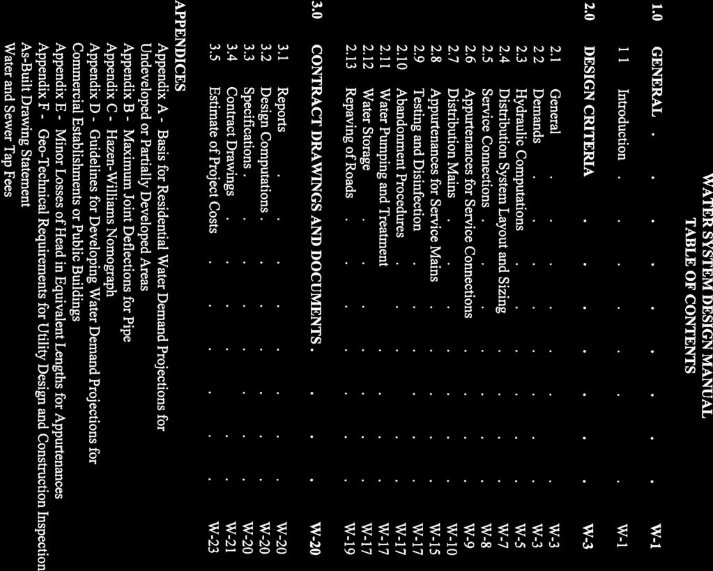
- Horace Bond
- 5 years ago
- Views:
Transcription
1
2

3
4 WATER SYSTEM DESIGN MANUAL 1.0 GENERAL 1.1 Introduction This chapter of the Middletown Design Manual outlines the policies, minimum design criteria and design procedures for the preparation of feasibility reports and construction plans and specifications for Town-maintained and on-site water system improvements. Developers and/or Design Engineers shall check with the Town Office of Planning and Zoning to determine the availability of water at the site of a proposed subdivision Town Policy a. Town-Maintained Facilities The parts of the water supply system which are considered as the property and responsibility of the Town of Middletown are the water mains, appurtenances and that portion of the water services up to and including the curb stop or valve just inside the property line. The water supply and distribution system within the Town s rights-of-way and easements for Middletown is maintained by the Town of Middletown. b. On-Site Facilities The parts of the water services which lie within private property are the responsibility of the owner and are constructed and maintained by the Owner. c. Requirements for Water Service 1. All properties will be connected to the water system of Middletown. a.) Each building shall be serviced by a separate water tap. (1) Multiple dwelling units such as an apartment dwelling, duplex or residential unit with apartment(s) may be served by a single water tap but will be billed quarterly water and sewer fees based on the number of dwelling units in the building. TOWN OF MIDDLETOWN, MD W-1 (05/99)
5 b.) c.) d.) (2) Buildings with offices or commercial enterprises will be billed for each common male/female restroom for use of leasees. If any unit has private facilities in addition to the common facility(s), additional billing will be made for each private facility. (3) Property owners are responsible for all fees assessed to rental properties if not paid by the tenant or leasee. If an additional building is constructed on an existing lot which has a water tap, the new structure must be provided with an additional water tap. If a lot containing more than a single structure is subdivided to provide separate lots for each structure, the lot(s) without water tap(s) must provide these taps as a condition of subdivision. If a lot containing a single structure is subdivided, each structure erected upon the new subdivided area must procure a water tap prior to obtaining a building permit Definitions a. Service Connections: Water mains connecting the distribution mains to individual homes, buildings, or facilities for both consumptive use and fire protection. b. Distribution Mains: Water mains connecting the transmission mains to the service connections. The distribution mains provide area-wide fire protection. Generally, the distribution mains will be in a grid or branched configuration. c. Transmission Mains: Large diameter mains connecting the treatment plant with the distribution mains. d. Average Day Demand: Average day demand is the volume of water used in the year divided by 365. e. Average Day Rate (Average Day): Average day rate is the average day demand volume divided by a one-day period, expressed in gallons per minute (gpm) or million gallons per day (MGD). f. Maximum Day Demand: Maximum day demand is the largest volume of water used in one day during the year. TOWN OF MIDDLETOWN, MD W-2 (05/99)
6 g. Maximum Day Rate (Max. Day): Maximum day rate is the water used during the maximum day divided by a one-day time period expressed in gpm or MGD. h. Peak Hour Demand: Peak hour demand is the largest volume of water used in one hour. i. Peak Hour Rate (Peak Hour): Peak hour rate is the peak hour demand volume divided by 60 minutes, expressed in gpm; or multiplied by 24 hours, expressed as MGD. j. AWWA: American Water Works Association. k. Town: Burgess of Commissioners of Middletown. 2.0 DESIGN CRITERIA 2.1 General For the Engineer's guidance, below are listed major elements constituting the design of a Water Main Utility Design project: a. Pipe size and alignment b. Profile, with all elevations c. Property data (lot dimensions, all sides of affected properties, liber/folio number, owner) d. Rights-of-way e. Specifications and notes f. Cost estimate 2.2 Demands a. The sizing of major components of the Town water supply system such as major transmission mains, storage facilities, and booster pumping facilities, are the responsibility of the Town and beyond the scope of this manual. The Town may require developers to design these facilities as well as finance and construct them. Should this be the case, the Town must be consulted for specific design criteria. TOWN OF MIDDLETOWN, MD W-3 (05/99)
7 b. The design engineer who is responsible for the extensions of distribution mains shall follow the guidelines in this manual for the derivation of design flows. The calculation of water demands will usually require extension of the average daily rate for the facility, application of a peaking factor to derive the maximum daily rate, then addition of the fire flow requirement. c. Generally, the design engineer will be selecting distribution mains of 12-inch diameter and smaller, and often will be required to provide the minimum size mains, which are listed later in this Chapter Residential Demands Studies have shown that the quantity of average daily water use and peaking factor for residential areas are related to lot size. This is due to increases in persons per dwelling unit, per capita consumption, and greater lawn sprinkling as the lot sizes increase. The information in Appendix A shall be used to derive residential demands and peaking factors Commercial and Industrial Demands The estimation of average daily water consumption and peaking factors for commercial demands are greatly dependent on the type of facility. With the exception of industries using process water, the fire demand generally is the major component of the design used to size distribution main extensions and service connections to buildings having sprinkler systems. The design engineer shall refer to the Frederick County plumbing code for derivation of building design flows if the number of fixture units is known. If the type of business is known, but a specific fixture count is not known, use Appendix D to estimate water demand. For undeveloped land, use Appendix A to derive Commercial and Industrial water demand according to zoning. TOWN OF MIDDLETOWN, MD W-4 (05/99)
8 2.2.3 Fire Flow Rates Residential: 1 Single Family Townhouses Garden Type Apartments High Rise Apartments Commercial: 1 Regional Shopping Centers Industrial: 1 Institutions: 1 Hospitals Schools 1,000 gpm at 25 psi residual 1,500 gpm at 25 psi residual 2,000 gpm at 25 psi residual 2,500 gpm at 25 psi residual 3,000 gpm at 25 psi residual 3,000 gpm at 25 psi residual 2,500 gpm at 25 psi residual 2,500 gpm at 25 psi residual Office Building Complex: 1 3,000 gpm at 25 psi residual 1 Above fire flows to be used in the absence of site specific data from fire underwriters or construction plans which would permit a determination of fire flow requirements using insurance industry standards (Insurance Services Office -ISO). Consideration will be given to reducing the requirement where proposed construction includes sprinkler system; refer to current ISO recommendations. 2.3 Hydraulic Computations General The hydraulic design of water mains shall be in accordance with the requirements of the American Water Works Association or Pipeline Design for Water and Wastewater, ASCE, 1975, and the additional guidelines and criteria in this Chapter Design Flows and Residual Pressures a. Service connections, distribution mains and transmission mains shall be sized based on the following design flow rates and residual pressures: Maintain a minimum of 25 psi at ground level anywhere in the system under all conditions. or Normal working pressure 60 psi and not less than 35 psi residual pressure at the service connection during peak hourly rate. TOWN OF MIDDLETOWN, MD W-5 (05/99)
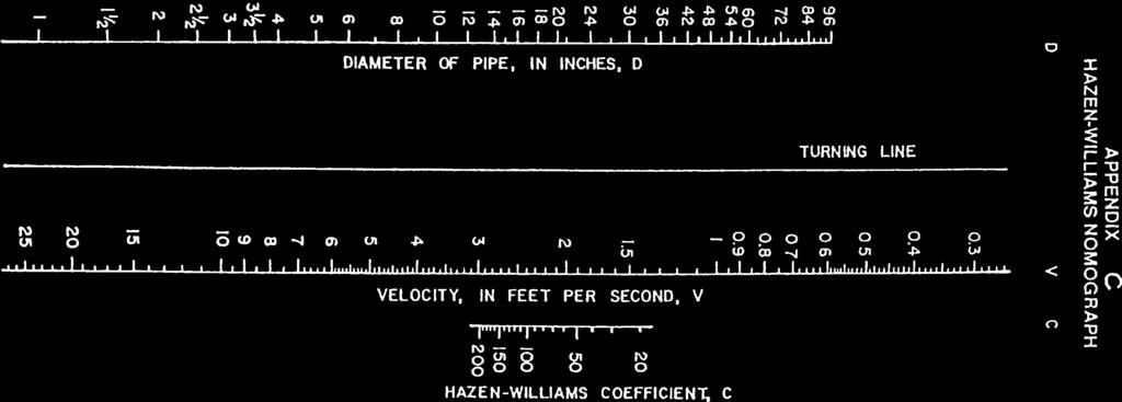
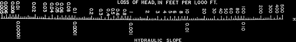
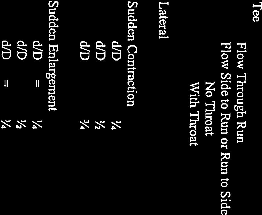
9 ...Whichever is more critical... b. In some locations, the main size will be determined by the flow rate required to refill a storage facility which may be more critical than the above requirements. The Town will identify this requirement, if applicable Flow Velocities Although the flow velocities and direction may vary considerably in distribution mains, there are upper and lower velocity bounds that indicate to the design engineer that design weaknesses may exist. The following are useful guidelines: a. Velocities greater than 7 fps at design flow This condition may produce large friction losses and high potential for valve and joint damage due to water hammer. b. Velocities less than 0.5 fps at design flow This condition indicates that the main may be oversized. Future maintenance problems may result from siltation at valves and there may be water quality degradation Hazen-Williams "C" and Minor Losses a. The total head loss at the point of discharge for design flows shall be the sum of both friction and minor losses. The elevation difference between the source and discharge point shall be algebraically added to the total head losses. b. Head losses for new pipes shall be computed using the nomograph in Appendix C and the following coefficients: TOWN OF MIDDLETOWN, MD W-6 (05/99)
10 Type Pipe Diameter Hazen-Williams "C" Service Connections Copper 3/4 inch - 3 inch 130 DIP 3 inch 100 Distribution Mains DIP 4 inch - 8 inch 100 DIP 10 inch - 12 inch 110 DIP 16 inch - 24 inch 120 Transmission Mains DIP 16 inch - 20 inch 120 DIP 24 inch and larger 130 c. Minor losses due to fittings and valves shall be included as equivalent lengths of pipe as shown in Appendix E or as fractional losses in velocity head as described in Pipeline Design for Water and Wastewater, ASCE, 1975, or other hydraulics texts. 2.4 Distribution System Layout and Sizing General Extensions of distribution mains will normally be on a grid basis with interconnecting nodes at street intersections Residential Subdivision (New and Existing) The water distribution system for residential areas where fire protection is to be provided shall meet the following criteria: a. Minimum size of water mains shall be 8-inches. b. All water mains shall be looped, except where capped for future extension to adjoining property. A fire hydrant shall be placed at the end of the main and may be relocated at the time the main is extended, if approved by the Office of Planning and Zoning. c. A fire hydrant shall be placed within ten (10) feet of the terminus of all dead end mains. TOWN OF MIDDLETOWN, MD W-7 (05/99)
11 2.4.3 Commercial and Industrial Areas 2.5 Service Connections The water distribution mains for Commercial and Industrial areas where fire protection is to be provided shall meet the following criteria: a. Minimum size shall be 8-inches. b. All water mains shall be looped, except where capped for future extension to adjoining property. A fire hydrant shall be placed at the end of the main and may be relocated at the time the main is extended, if approved by the Office of Planning and Zoning. c. A fire hydrant shall be placed within 100 feet of the terminus of all dead end mains. d. Where design flow rates exceed 1500 gpm, hydraulic computations shall be provided General House connections for water shall be built to the meter vaults near the property line for all lots within a proposed development. All 2 and smaller meters will be installed into the water meter vault and settings by Town staff. All adjacent improved lots which are not part of the proposed development, but which may be served by the waterline, shall be shown on the contract drawing Location Sizing On the plans, indicate service connections 15 feet from the property line on the high end of the lot or at a location desired by the homeowner if the lot is already developed. Meter vaults shall be placed near the property lines and shall not be constructed in the curb, sidewalk or driveway. a. Service connections must be no smaller than 1. Twin house connections will not be permitted. b. For other than a residential dwelling, determine the water supply demand pursuant to the criteria in Section 2.2. The velocity in the service connection must not exceed 8 fps. TOWN OF MIDDLETOWN, MD W-8 (05/99)
12 2.5.4 Cover Cover over service lines must be a minimum of 3 feet 6 inches or as required by the Frederick County Plumbing Code, whichever is greater Clearances Water house services shall be placed 7 feet horizontally from sewer house connections and a minimum of 1 foot clear above the sewer house connection or as required by the Frederick County Plumbing Code Materials Piping material must be Type 'K' copper for residential service lines and ductile iron or copper for larger sizes Cross Connections No cross connections where contamination can enter the potable water supply are permitted. No cooling water or condensate may be returned to the potable water supply line. All interconnections shall be approved by the Town and other appropriate reviewing authorities. 2.6 Appurtenances for Service Connections Meters (Location) Meters shall be located outside the house in a vault with a radio transmitter also located in the vault. The vault will be located just inside the property line. a. Only Sensus meters are permitted. b. All meters must be purchased from the Town. Town staff will install the meter into the setter in the meter vault after payment is received and on a certain schedule Meters (Sizing) Meter types for Commercial, Industrial and Institutional applications shall be determined by the Town or authorized agent. Meters shall be installed to record all water usage, including fire flow. a. Valves TOWN OF MIDDLETOWN, MD W-9 (05/99)
13 A valve or corporation cock shall be provided on the water main side of each meter installation. b. Backflow Prevention Device Installation 2.7 Distribution Mains Reduced pressure backflow prevention devices shall be required on all services to commercial/industrial or individual facilities and shall be located immediately adjacent to the outlet side of the water meter, fully accessible. Refer to AWWA, Cross Connection and Backflow Prevention for additional design criteria. Installation of all service connections and appurtenances shall be in accordance with latest AWWA standards or manufacturer's recommendations. Such requirement shall be noted in specifications and on contract drawings Description Distribution mains are 12 inches and smaller in diameter. For larger mains, design engineer should consult with the Town regarding special design criteria Location a. In new subdivisions Lay water mains 7 feet from the centerline of the road right-of-way, generally on the side of the road toward high ground (on opposite side of road from the sanitary sewer). Locate mains within the pavement area, wherever possible, no less than 5 feet from curb or proposed curb. Water mains shall not be located under curb or sidewalks, except where the water main crosses in a perpendicular fashion. b. In existing developments with curbs Generally, location must be the same as in new subdivisions. The location of other existing and proposed utilities must be fully considered. c. In existing developments with pavement and no curbs Generally, location must be the same as in new subdivisions. An alternative location with the approval of the Town will involve locating the main 2 feet outside the edge of pavement on the opposite side of the TOWN OF MIDDLETOWN, MD W-10 (05/99)
14 2.7.3 Size road from the sanitary sewer, except that the main must not be laid under a future curb. The location of other existing and proposed utilities must be fully considered. d. Where utilities are extended to accommodate development, they shall be extended across the full frontage of the property being serviced. e. In parks and public rights-of-way, where location of a water main would require removal of trees, the design engineer shall obtain approval of the Town for tree removal. f. Distribution mains may be designed on a curved alignment to reduce the number of bends. Along curves, the water main may be deflected at each joint within the limits given in the Appendix. g. All water utility easements outside of road right-of-ways shall be 20 feet minimum width. No other utilities will be allowed in the water easement without the Town's written approval. a. Distribution Mains Shall be 8-inch minimum size and shall be interconnected at all intersecting streets, with valves on all mains at the intersection. Where the required flow exceeds the capacity of an 8-inch main or of the existing system, larger mains will be required. b. Distribution mains shall be sized to provide the required design flow rate and residual pressures as detailed herein. c. Transmission Mains Materials Sizing shall be based on a computerized network analysis performed by the design engineer or as provided by the Town, if available. a. All distribution and transmission mains and fittings shall be Ductile Iron, double cement lined (latest AWWA C-151) with standard mechanical joints or push-on joints. TOWN OF MIDDLETOWN, MD W-11 (05/99)
15 b. At bridge crossings, 16-inch and smaller ductile iron pipe shall have fiberglass insulation with vapor jacket wrapped by a full metal jacket for all exposed piping. c. Expansion joints, insulated couplings and rollers shall be provided as required Installation Installation of all service connections and appurtenances shall be in accordance with latest AWWA standards or manufacturer's recommendations. Such requirement shall be noted in specifications and on contract drawings Cover Over Pipe a. Normal cover over water mains shall be 4 feet except at crossing over other utilities, where a minimal cover of 3 feet or a maximum cover of 9 feet may be allowed. b. In new subdivisions Cover shall be measured from finished grade of road or as specified by the Town. Roads shall be graded to subgrade before water mains are laid. c. In existing or ungraded roads Clearances Established grades of roads shall be obtained from the Town and are generally the proposed future finished grade. If such grades are not available, the design engineer shall submit proposed grades for approval by the Town. If established grade is at or below existing surface, cover shall be measured from established grade. If established grade is above existing surface, cover shall be measured from existing surface. In no case, however, shall the cover deviate from the minimum or maximum cover indicated in a. Clearances shall be measured between outside of pipes. b. Crossing Sanitary Sewer Water main shall have minimum clearance of 18 inches above sewer. This vertical separation shall be maintained horizontally for a distance of 10 feet or as required by the Maryland Department of the Environment. TOWN OF MIDDLETOWN, MD W-12 (05/99)
16 c. Parallel to Sanitary Sewer A horizontal distance of at least 10 feet shall separate water main and sewers or as required by the Maryland Department of the Environment. d. Crossing Other Utilities Water mains shall have minimum clearance of eighteen inches where crossing utilities. EXCEPTIONS: When specified clearance is not physically possible between sewer and water in a new subdivision or in locations where sewer is built along roads having existing water mains, the sewers shall be designed according to Sewer Design Standards of Frederick County. If sewers already exist in a road, and water main cannot be built to specified clearances, ductile iron pipe with mechanical joints or other approved safety joints shall be used for the water mains. These installations shall be pressure tested to assure water tightness before backfilling. The Town shall be consulted to discuss the use of concrete encasement of the sewer and/or water main. The Developer or Engineer shall propose options to the Town for approval to ensure all possible measures are considered and implemented to avoid possible contamination of the water supply Structural Considerations a. Buttresses and Anchors Buttresses and anchors shall be required at all fittings which achieve a change in pipeline direction, such as tees, fire hydrants, bends and dead ends, thrust restraint is necessary. Buttresses and/or anchorage blocks are the two means of achieving thrust restraint. The design engineer shall decide what is appropriate for each particular situation based on an analysis of such factors as soil conditions, clearance requirements, constructability, future expansion and cost. Buttresses and Anchorage blocks are concrete placed against undisturbed soil designed for restraint of thrust forces in pressurized piping systems. The Town reserves the right to require a soils analysis. b. Restrained Joints If the soils at the project site are unusually poor, or other factors such as cost, space limitations, or future construction so indicate, restrained pipe joints shall be designed. The joint restraint may be either harnesses or mechanical joints with retainer glands for mains up to 16-inch diameter. TOWN OF MIDDLETOWN, MD W-13 (05/99)
17 Restrained joint types for larger mains shall be approved by the Town prior to proceeding with design. The design shall account for test pressures, soil frictional resistance and effect of groundwater as a minimum. The Town reserves the right to require a soils analysis. c. Jacking and Tunneling Where mains are being designed to cross railroads, state highways, or other roads, on which service cannot be interrupted, the water main shall be installed in a sleeve, tunneled or jacked under the road. The sleeve size and material and the method of tunneling or jacking shall be approved by the owner of the road or the railroad being crossed. The sleeve diameter shall be sufficient to permit the proper positioning of the water main within the sleeve. Water mains installed in sleeves shall have restrained joints throughout the length of the sleeve. The annular void between the main and the sleeve shall be completely filled with grout. Water mains installed in sleeves shall be equipped with sufficient valves to shut-off all flow through the sleeved section. In the case of dead end main, one valve upstream will be sufficient; in other cases, a valve at each end is required. d. Design Loads and Pipe Design In cases where deemed necessary by the Town, the design engineer shall submit all calculations necessary to support the selection of the type and class of pipe indicated on the Contract Drawings. The calculations may account for the following: e. Corrosion Protection Vehicle or railroad loads (H-20, E-80, etc.); Pipe loading factors (dead, live, impact); Internal pressure (static, dynamic, surge); Installation trench configuration. If soil tests or inspection of existing utilities in the project area reveals evidence of, or potential for, corrosion, the Town shall be notified of the condition. Should the Town deem it necessary, the design engineer shall design suitable galvanic and/or cathodic corrosion protection measures using AWWA Controlling Corrosion Within Water Systems, The Town reserves the right to require a soils analysis for corrositivity. TOWN OF MIDDLETOWN, MD W-14 (05/99)
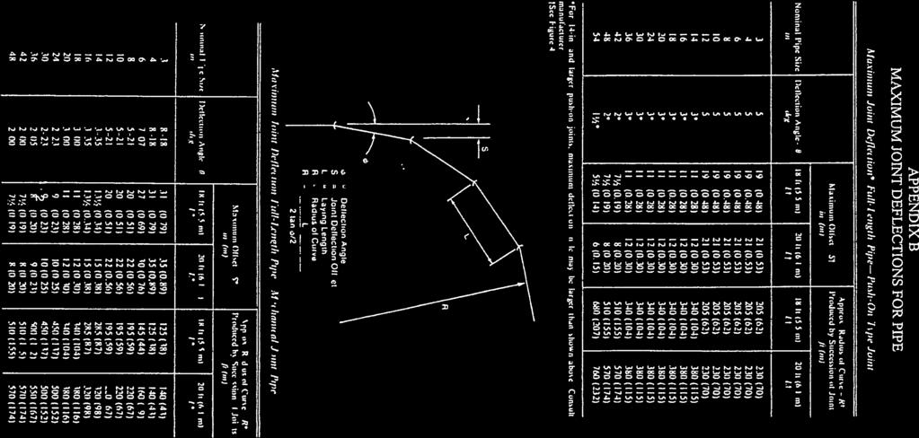
18 f. Deflection of Pipe 2.8 Appurtenances for Service Mains Valves The maximum deflection allowed shall be as shown in Appendix B of this Manual. a. Size and Type Mains 4-inches to 16-inches shall have valves of the same size as the main. Valves shall be resilient seat gate valves with non-rising stem. All valves 16-inches and larger shall have bevel gears and an enclosed gear case. b. Location Valves shall be installed on the loop or network at such places as to isolate the branch sections as may be necessary with a maximum spacing of 1500 feet. They shall be installed on all fire hydrant leads as close to the water main as is feasible. A valve shall be placed on all branch lines, regardless of size, near the main. Valves at intersections shall be placed on projection of road right-of-way lines. In no case shall the valve be placed in the sidewalk or less than ten feet (10') from another valve Tapping Sleeves and Valves Fire Hydrants Where Used: Tapping sleeves and valves on ductile iron mains to serve as line valves shall be used for all connections 6-inches and larger to any existing main 12-inches or larger where more than 10 domestic services would be shut off during installation of a standard tee. The main being tapped may be the same size as the proposed main or tapping valve, but the tapping cutter shall be 1/4-inches or more undersized. a. Size and Type Hydrants shall be a minimum of 6-inches. The engineer shall submit to the Town a scale map 1 inch = 200 feet showing area streets, water mains and proposed location of fire hydrants for the Town's use and for transmittal to the Fire Department. Fire hydrants shall be Mueller, Model A-423 or Kennedy Model K81. Each hydrant shall have one (1) 4½ inch diameter pump nozzle and two (2) 2½ inch hose nozzles, nozzle gaskets, TOWN OF MIDDLETOWN, MD W-15 (05/99)
19 5¼ inch valve, 1½ inch pentagonal operating nut, open left. Both the hose nozzles and pumper nozzle shall have National Standard Thread. Hydrants shall be designed for 4½ foot bury and 6 inch mechanical joint inlet. b. Location Hydrants shall be located in a pattern approved by the Town Engineer or his duly authorized representative and shall be located so as to provide vehicular clearance from the street. Hydrants not at intersections shall be located in relation to property lines in order to avoid interference with future driveways. c. Spacing Hydrant spacing in residential areas composed of detached or semidetached one- and two-family dwellings shall be at each street intersection and at 500-foot maximum intervals between intersections. Hydrant spacing in other residential areas and all other uses of property shall be at each street intersection and at 300-foot maximum intervals between street intersections Air and Vacuum Release Valves a. The proper ventilation of distribution and transmission mains is often overlooked by design engineers. Trapped air pockets can significantly reduce the capacity of the mains as well as cause increased pumping heads and corresponding higher pumping costs. The following guidelines shall be used to locate air and vacuum release valves: Peaks in profiles Abrupt increase in downward slope Abrupt decrease in upward slope Long ascents ft to 3000 ft intervals Long descents ft to 3000 ft intervals Long horizontals ft to 3000 ft intervals Pumps - on the discharge side of pump having suction as close to the check valve as possible b. In general, fire hydrants shall be placed at all high points along the main and at the terminus of dead end mains. TOWN OF MIDDLETOWN, MD W-16 (05/99)
20 2.8.5 Valve Vaults a. Mains 12-Inches and Smaller For valves and for tapping sleeves and valves, use the Frederick County Standard Roadway Valve Box. b. Mains Larger than 12-Inches 2.9 Testing and Disinfection For valves, except butterfly-type, use reinforced concrete vaults as approved by the Town. For tapping tees and valves, use concrete vaults as approved by the Town. The contract documents shall provide for hydrostatic testing of newly laid mains as described in the Frederick County Standard Specifications. Hydrostatic tests shall be performed for pressure retention and leakage. Disinfection shall be in accordance with AWWA C Abandonment Procedures Abandoned service connections shall be cut and plugged at the service main, and the meters removed and salvaged if their condition permits reuse. Distribution mains that are to be abandoned shall be plugged at the point of abandonment and on each side of any existing valves, and the valves and hydrants removed and salvaged if their reuse appears practicable. Any necessary buttresses or anchorage required shall be designed in accordance with Frederick County Standard Details Water Pumping and Treatment A detailed presentation of design criteria for pumping and treatment facilities is beyond the scope of this manual. The Town will specify the exact requirements to be met by the design of these facilities Water Storage General A water system must be able to meet the peak hour demand during the maximum demand day to be effective. However, it is not economically feasible for domestic water systems to provide sufficient supply capacity to meet these peak demands. Therefore, to stabilize pressure and also to provide the necessary reserve capacity to meet peak demand period, it is the usual practice to provide storage reservoirs as an integral part of any distribution system. TOWN OF MIDDLETOWN, MD W-17 (05/99)
21 During periods of peak demand, such as fire conditions, the required volumes of water that cannot be provided from the system's supply source are taken from the system's distribution storage. During periods of low demand, the excess water from the supply source returns to storage until the facilities are again full, completing the cycle. The criteria used to determine the proper size of storage facilities can best be understood in terms of the functions which storage facilities are intended to perform. These functions may be summarized as follows: a. To provide an equalizing reserve. b. To provide a fire reserve. c. To provide an emergency reserve Equalizing Storage The equalizing reserve is the quantity of water needed to even out or "equalize" the system demands during a day's operation. By providing this reserve, the storage facilities make it possible to operate the treatment facilities and pumping stations at a relatively uniform rate. When the system demand is higher than the supply rate, water is withdrawn from the storage facilities. Conversely, when the system demand is below the supply rate, water is returned to storage to ensure that an adequate quantity is available for the next period of high demand. In general, systems which have an equalizing reserve equal to 20% of their maximum daily demand operate satisfactorily Fire Reserve The size of the fire reserve is indirectly set by the Insurance Services Office (ISO), formerly known as the National Board of Fire Underwriters. This agency sets standards for the amount of fire flow that should be available at various points in a community Emergency Reserve The emergency reserve is included as a safeguard against disruptions in the supply source, ruptured water mains, well-pump interruptions, or other circumstances which would exert an additional demand on the storage facilities. Normally, the quantity allotted for emergencies is 25% of the total effective storage volume. TOWN OF MIDDLETOWN, MD W-18 (05/99)
22 2.13 Repaving of Roads General a. All Town construction contract specifications shall include a "patchpave" requirement as follows: Properly compacted borrow aggregate backfill shall be placed and compacted from 3 inches below the pipe to the bituminous pavement subgrade. The pavement replacement shall consist of a base course of asphaltic concrete of at least a thickness equivalent to the original pavement section, the original wearing course cut back two-feet on all edges of the excavation and a new asphaltic concrete wearing course of at least a thickness equivalent to the original wearing course. Other road pavement sections will receive similar treatment. The base course shall be a minimum of 4-inches, and the wearing course shall be a minimum of 2-inches. b. Patch-paving as outlined above is to be accomplished whether the roadway is to be re-paved or not. c. House connection installations will require the same specifications for patch-paving. d. All paving/repaving work will be accomplished in accordance with the Town Road Specifications or Design Manual. A "road cut" permit must be obtained from the Town when excavating within an existing Town maintained roadway. e. Pavement patch in County or State roads shall comply with the requirements of the jurisdiction Timing of Patch-paving and/or Repaving a. Specifications will provide that patch-paving shall be accomplished immediately after backfilling and achieving specified compaction for connection and small extension contracts; and at no greater than seven (7) calendar day intervals for larger projects. Temporary "cold patch" shall be required for patches not immediately patch-paved. The Town must be consulted if immediate patch-paving cannot be accomplished. Cold patching must be maintained by the Developer to the Town's satisfaction. The placement of steel plates over trenching may be approved by the Town on a case-by-case basis. TOWN OF MIDDLETOWN, MD W-19 (05/99)
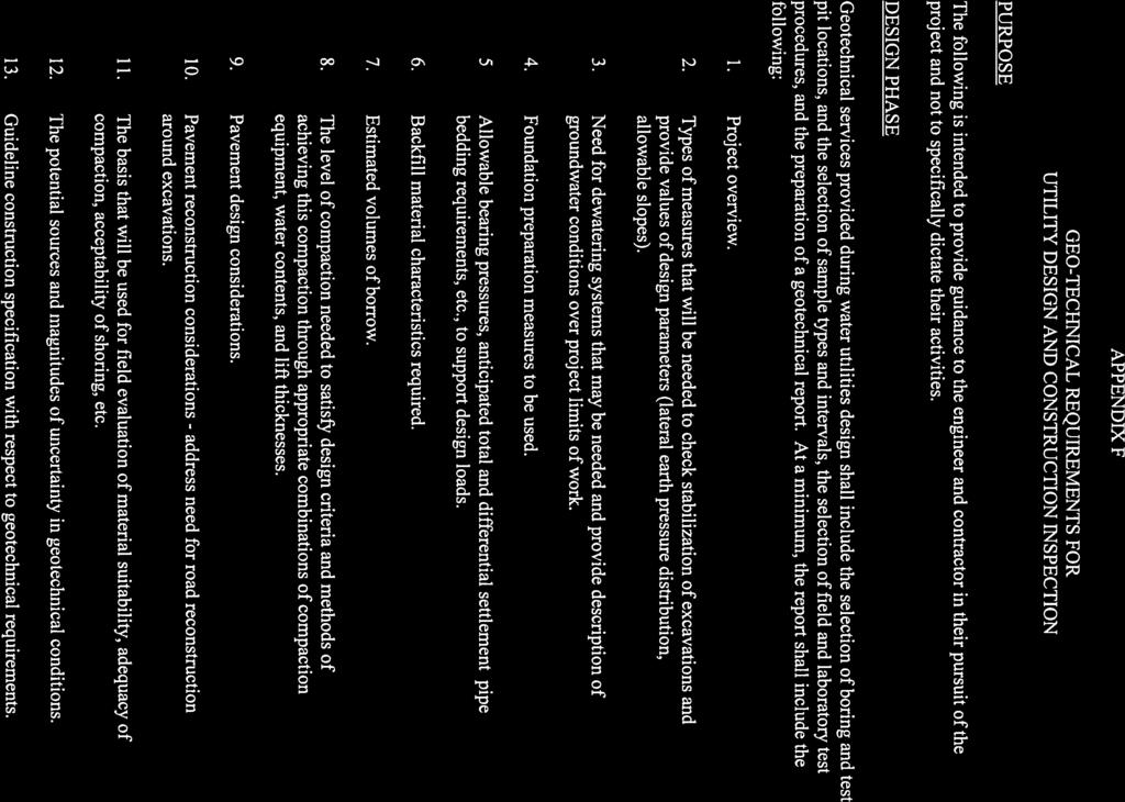
23 b. Repaving shall be specified to be accomplished in one continuous effort to best assure economy and consistency of quality work Traffic Control All water utility construction projects shall have an approved traffic control plan, using requirements of the Manual on Uniform Traffic Control Devices. 3.0 CONTRACT DRAWINGS AND DOCUMENTS 3.1 Reports For mains larger than 12-inches, three copies of a preliminary report shall be submitted to the Town. The report shall include a sketch of the preliminary layout and a summary of the design data. 3.2 Design Computations 3.3 Specifications a. Design engineers shall submit three copies of design data and calculations for all water projects. The computations shall be in accordance with methods presented in this manual. b. The design data and computations shall include: average and peak demands, fire demand, and future requirements. c. Design computations for all special structures shall be submitted. Where information pertinent to design, such as borings, has been collected, this information shall be submitted to the Town. The locations of borings shall be shown on the plan sheets, and the boring logs shall be included in the Contract Documents. See Appendix F for Geo-Technical Requirements. In addition, the Town reserves the right to require borings and geotechnical information. Contract specifications shall utilize the Town of Middletown Specifications or, in the absence of Town Specifications, the Frederick County Specifications will apply. TOWN OF MIDDLETOWN, MD W-20 (05/99)
24 3.4 Contract Drawings Preparation Plan Water main contract drawings shall be prepared on drawings separate from drawings detailing the road design. Separate drawings shall be used for each street Profile a. Scale: 1 inch = 50 feet. b. Method of Indicating Location Generally, water mains and structures shall be located in Plan by dimensions from property markers or other well defined physical features. However, in areas where physical features are not available, coordinates of structures and bearings of water mains based on the Maryland Coordinate System NAD 83/91 shall be used. c. Fittings A list of all valves and fittings required shall be shown on each drawing. d. Contract drawings shall include the property line surveys and all lot dimensions of the land bordering water extensions and shall indicate the names of the present owners of such property with the recording reference number of the deed, lot numbers, house numbers, subdivision names and block numbers, as well as existing rights-of-way or easements. When rights-of-way must be obtained, a right-of-way drawing for each property shall be provided, accompanied by a written description of each right-of-way. Profiles shall be shown for all water mains. Profile shall be on same sheet as the Plan. a. Scale Scale of all profiles shall be 1 inch = 50 feet horizontal; 1 inch = 5 feet vertical. Water main profiles on straight streets TOWN OF MIDDLETOWN, MD W-21 (05/99)
25 shall be shown to correct scale. On curved streets, horizontal distances between structures shall be plotted using length of street centerline between radial projections to structures. The true length between structures shall be shown by figures. b. Road Grades Approved established grades shall be obtained from the Town. When such grades are not available, they shall be established by the design engineer and submitted to the Town for approval. The established grade (noted as top of curb or centerline) shall be shown. Where water main is located in present or proposed pavement or shoulders, the existing centerline grade of road shall be shown. Where water main is outside pavement or shoulders for a length greater than 50 feet, existing ground over water main shall be shown and labeled. c. Water Main on Fill Other Utilities Where water main is to be constructed on fill, a profile of the undisturbed earth (at water main location) shall be shown. Other existing and proposed utilities shall be shown accurately and clearly in Plan and Profile Location and Design Information A Location Plan showing well known streets at a scale of 1 inch = 200 feet shall appear on the first drawing of each set of Contract Drawings. A schematic layout of the proposed extensions to the water system and adjacent existing lines shall be shown. The location of existing valves which must be shut off when the new line is connected must be shown. Existing and proposed fire hydrants shall also be shown Special Details Structures or details not included in the Standard Details shall be detailed clearly on the Contract Drawings, preferably where the detail is located in Plan. TOWN OF MIDDLETOWN, MD W-22 (05/99)
26 3.4.8 One (1) copy of the As-Built drawings on mylar plan sheets with the statement and Engineer's signature, as shown in the Appendix, shall be submitted to the Office of Planning and Zoning within thirty (30) days of completion and acceptance of the work by the Town and on computer or GIS diskette in a format approved by the Office of Planning and Zoning. 3.5 Estimate of Project Costs The engineer shall submit an estimate of project costs for each contract, including contingent items and a 50% contingency based on the total cost of the project. TOWN OF MIDDLETOWN, MD W-23 (05/99)

27


28
29

30

31


32
33

34

35

36

37

38


39


40

41

42
43


44

45


46


47


48


49


50


51

52

53


54
55


56

57


58

59
60
TABLE OF CONTENTS PART III MINIMUM DESIGN STANDARDS Section 115 WATER DISTRIBUTION SYSTEM GENERAL SIZING LINES 115.
 TABLE OF CONTENTS PART III MINIMUM DESIGN STANDARDS Section 115 WATER DISTRIBUTION SYSTEM SECTION TITLE PAGE 115.1 GENERAL 115.1 115.2 SIZING LINES 115.1 115.3 DISTRIBUTION SYSTEM 115.2 115.3.1 Layout
UNIFORM DESIGN AND CONSTRUCTION STANDARDS FOR EXTENDING WATER DISTRIBUTION SYSTEMS SECTION 2 DESIGN STANDARDS
 UNIFORM DESIGN AND CONSTRUCTION STANDARDS FOR EXTENDING WATER DISTRIBUTION SYSTEMS SECTION 2 DESIGN STANDARDS DESIGN STANDARDS SECTION 2 INDEX ITEM DESCRIPTION 2.00 GENERAL STATEMENT 2.01 WATER DISTRIBUTION
CHAPTER 5 WATER SYSTEM DESIGN STANDARDS
 CHAPTER 5 WATER SYSTEM DESIGN STANDARDS TABLE OF CONTENTS CHAPTER 5 WATER SYSTEM DESIGN STANDARDS 5.00 Objective Page 1 5.01 Additional Referenced Standards Page 1 5.02 Special Design Problems Page 2 5.03
SECTION 4 - DESIGN STANDARDS FOR WATER DISTRIBUTION FACILITIES
 SECTION 4 - DESIGN STANDARDS FOR WATER DISTRIBUTION FACILITIES 4.1 GENERAL REQUIREMENTS 4.1.1 Water and fire protection distribution facilities are to be provided solely for the purpose of supplying potable
CHAPTER 8 WATER SUPPLY SYSTEM
 CHAPTER 8 WATER SUPPLY SYSTEM 8-1 INTRODUCTION These improvement standards shall govern the engineering design of all domestic water systems intended for operation and maintenance by the County of Sutter
CITY OF LA MARQUE, TEXAS CHAPTER 3 WATER SYSTEM DESIGN CRITERIA
 CITY OF LA MARQUE, TEXAS CHAPTER 3 WATER SYSTEM DESIGN CRITERIA CHAPTER 3 WATER SYSTEM DESIGN 3.1 WATER SYSTEM DESIGN GENERAL 3.1.1 Criteria for the design of water service and water distribution lines
City of Middletown WATER & SEWER DEPARTMENT 82 Berlin Street Middletown, CT TEL: (860) FAX: (860)
 FAX: (860)") City of Middletown WATER & SEWER DEPARTMENT 82 Berlin Street Middletown, CT 06457 TEL: (860) 638-3500 FAX: (860) 343-8091 GENERAL REQUIREMENTS WATER MAIN AND SERVICE INSTALLATION JANUARY 2017 WATER MAINS:
City of Middletown WATER & SEWER DEPARTMENT 82 Berlin Street Middletown, CT 06457 TEL: (860) 638-3500 FAX: (860) 343-8091 GENERAL REQUIREMENTS WATER MAIN AND SERVICE INSTALLATION JANUARY 2017 WATER MAINS:
SECTION 4 - DESIGN STANDARDS FOR WATER DISTRIBUTION FACILITIES
 SECTION 4 - DESIGN STANDARDS FOR WATER DISTRIBUTION FACILITIES 4.1. General Requirements 4.1.01 Water distribution and fire protection facilities are to be provided solely for the purpose of supplying
4A General Information A. Concept... 1 B. Conditions... 1
 Design Manual Chapter 4 - Water Mains Table of Contents TOC Table of Contents Chapter 4 - Water Mains 4A General Information 4A-1---------------------------------General Information A. Concept....... 1
Chapter 3: Permit Procedures and Requirements
 Chapter 1: General Provisions 1 1 Short Title 1 2 Jurisdiction 1 3 Amendments and Revisions 1 4 Enforcement Responsibility 1 5 Review Process 1 6 Prior Approval 1 7 Relationship to Other Standards 1 8
WATER MAIN EXTENSION DESIGN REQUIREMENTS
 This guideline provides minimum requirements for the design of new water main extensions. This guide is not to be used as a substitution for the detailed design of the water system. The Developer s Engineer
SECTION WATER MAINS CITY OF LEE S SUMMIT, MISSOURI DESIGN CRITERIA
 SECTION 6900 - WATER MAINS CITY OF LEE S SUMMIT, MISSOURI DESIGN CRITERIA 6901 DESIGN CRITERIA A. General 1. The design standards presented in the City of Lee's Summit Design Criteria are the minimum standards
Ivins City Standard Specifications for Design and Construction Part 2 Engineering and Design Standards
 2.9. WATER SYSTEM DESIGN Ivins City Standard Specifications for Design and Construction All culinary water mains and appurtenances shall be designed to provide for adequate future service for all contiguous
APPENDIX B STANDARD CONSTRUCTION DRAWING NOTES
 APPENDIX B STANDARD CONSTRUCTION DRAWING NOTES B-1 General Notes: SACWSD Standard Construction Drawing Notes 1. No work shall begin on any water or wastewater construction project until the construction
SECTION VII WATER. Concrete anchor and thrust blocks shall be provided at all discontinuities in accordance with Standard Details G-7.1 and G-7.2.
 SECTION VII WATER VII-1. DESIGN GUIDELINES Water pipelines and appurtenant structures within the jurisdiction of the City of Paso Robles shall be constructed in accordance with plans prepared by a Professional
PART II. - SPECIFICATIONS AND DESIGN STANDARDS TO CITY OF HEWITT, TEXAS SUBDIVISION ORDINANCE FOR PUBLIC WORKS CONSTRUCTION [TEXT]
![PART II. - SPECIFICATIONS AND DESIGN STANDARDS TO CITY OF HEWITT, TEXAS SUBDIVISION ORDINANCE FOR PUBLIC WORKS CONSTRUCTION [TEXT]](/thumbs/80/81891816.jpg "PART II. - SPECIFICATIONS AND DESIGN STANDARDS TO CITY OF HEWITT, TEXAS SUBDIVISION ORDINANCE FOR PUBLIC WORKS CONSTRUCTION [TEXT]") PART II. - SPECIFICATIONS AND DESIGN STANDARDS TO CITY OF HEWITT, TEXAS SUBDIVISION ORDINANCE FOR PUBLIC WORKS CONSTRUCTION [TEXT] A. - General. B. - Streets. C. - Stormwater drainage system. D. - Water
PART II. - SPECIFICATIONS AND DESIGN STANDARDS TO CITY OF HEWITT, TEXAS SUBDIVISION ORDINANCE FOR PUBLIC WORKS CONSTRUCTION [TEXT] A. - General. B. - Streets. C. - Stormwater drainage system. D. - Water
Permit for Construction of an Extension to a JEA Drinking Water Distribution System and/or JEA Wastewater Collection/Transmission System
 Permit for Construction of an Extension to a JEA Drinking Water Distribution System and/or JEA Wastewater Collection/Transmission System INSTRUCTIONS: This form shall be completed and submitted (in duplicate)
1. Required Minimum Flow:
 SECTION 6 6. 6.01 General The City of Castle Rock Water System Minimum Standards and Specifications are minimum base level performance, design, and construction standards used to maintain uniformity of
PART VII - WATER SYSTEM DESIGN CRITERIA
 PART VII - WATER SYSTEM DESIGN CRITERIA A. Water Distribution, General 1. The water system layout shall be approved by the City Engineer. The fire hydrant layout shall be approved by the Redwood City Fire
F. Provide at least 2 feet of vertical separation between a water line and any utility or stormdrain crossing it.
 Section 3 F. Provide at least 2 feet of vertical separation between a water line and any utility or stormdrain crossing it. 3.8 Highway Crossings The design engineer shall, prior to the design of any highway
CHINO VALLEY FIRE DISTRICT FIRE PROTECTION STANDARD
 CHINO VALLEY FIRE DISTRICT FIRE PROTECTION STANDARD SPECIFICATIONS Establishing Minimum Standards for as Related To Fire Protection STANDARD # 103 REVISED 04/01/19 PAGES 7 SCOPE: These specifications shall
WASHOE COUNTY DEPARTMENT OF WATER RESOURCES WATER DESIGN STANDARDS
 WATER DESIGN STANDARDS This section of the manual contains the Washoe County Department of Water Resources (DWR) standards for: Designing Water Distribution Facilities ( Design Standards ) 1.1 DESIGN STANDARDS
CURRENT NORTH LAS VEGAS ADDENDA
 SECTION 1 Section 1.01.73 Fire Service Meter ADD: Type I is not approved for installation in the City of North Las Vegas service area. Section 1.01.107 Pressure Reducing Valve (PRV) or Pressure Regulator
SECTION 13 WATER SYSTEMS
 TABLE OF CONTENTS SECTION 13 WATER SYSTEMS 13.1 PURPOSE AND DEFINITIONS... 1 13.1.1 Purpose... 1 13.1.2 DOU Water System... 1 13.1.3 Definitions... 1 13.2 GENERAL REQUIREMENTS... 6 13.2.1 Authority and
CITY OF SASKATOON DESIGN AND DEVELOPMENT STANDARDS MANUAL SECTION FOUR WATER DISTRIBUTION SYSTEM
 CITY OF SASKATOON DESIGN AND DEVELOPMENT STANDARDS MANUAL SECTION FOUR WATER DISTRIBUTION SYSTEM 2018 TABLE OF CONTENTS Section Four Water Distribution System SECTION PAGE NUMBER 1. Objective...1 2. Submissions
SEWER SYSTEM DESIGN GUIDELINES
 SEWER SYSTEM DESIGN GUIDELINES PART 1 GENERAL 1.1 GENERAL GUIDELINES A. The following sewer system design guidelines are based on Federal, State and Local health requirements, and the Berkeley County Water
TECHNICAL SPECIAL PROVISION FOR FINANCIAL PROJECT ID:
 TECHNICAL SPECIAL PROVISION FOR 1001 WATER DISTRIBUTION SYSTEM FINANCIAL PROJECT ID: 200105-7-52-01 The official record of this Technical Special Provision is the electronic file signed and sealed under
A. Introduction 7 1. Purpose 7 2. Authority 7 3. Contact 8 4. Plan Submittal Process 8 B. Design Standards General 11 a. Future Extensions 11
 A. Introduction 7 1. Purpose 7 2. Authority 7 3. Contact 8 4. Plan Submittal Process 8 B. Design Standards 11 1. General 11 a. Future Extensions 11 b. Design Calculations 11 c. Easements and Property 12
WASHOE COUNTY DEPARTMENT OF WATER RESOURCES GRAVITY SEWER COLLECTION DESIGN STANDARDS
 GRAVITY SEWER COLLECTION DESIGN This section of the manual contains the Washoe County Department of Water Resource s (DWR) standards for: Designing Gravity Sewer Collection Facilities ( Sewer Design Standards
T a b l e o f C o n t e n t s
 C i t y o f G l a d s t o n e P u b l i c W o r k s D e s i g n S t a n d a r d s T a b l e o f C o n t e n t s SECTION THREE SANITARY SEWER REQUIREMENTS... 1 3.0000 SANITARY SEWERS... 1 3.0010 General
Contact the Jurisdictional Engineer for materials allowed by each jurisdiction.
 Design Manual Chapter 3 - Sanitary Sewers 3C - Facility Design 3C-1 Facility Design A. Capacity of Pipe Pipe sizes 15 inches and smaller should carry the peak flow at a depth of no more than 0.67 of the
WASHOE COUNTY COMMUNITY SERVICES DEPARTMENT GRAVITY SEWER COLLECTION DESIGN STANDARDS
 GRAVITY SEWER COLLECTION DESIGN This section of the manual contains the Washoe County Community Services Department (CSD) standards for: INDEX Designing Gravity Sewer Collection Facilities ( Sewer Design
DUKE UNIVERSITY CONSTRUCTION STANDARDS
 1 33 11 00 Water Utility Distribution Piping 1. Introduction A. Duke University owns and operates the water distribution system throughout the campus boundaries; however, water is supplied by the City
3.0 DESIGN CRITERIA FOR SANITARY SEWER FACILITIES
 3.0 DESIGN CRITERIA FOR SANITARY SEWER FACILITIES All sanitary sewers shall be designed in accordance with these Design Standards, LBWD Rules and Regulations, and to accepted engineering principles. In
SECTION MEASUREMENT AND PAYMENT
 SECTION 01026 PART 1 GENERAL 1.1 SECTION INCLUDES A. Explanation and Definitions B. Measurement C. Payment D. Schedule of Values E. Application for Payment 1.2 EXPLANATION AND DEFINITIONS A. The following
1. Will have water lines designed by a North Carolina Registered Professional Engineer.
 03/07/16 DEVELOPER/OWNER RESPONSIBILITES 1. Will have water lines designed by a North Carolina Registered Professional Engineer. 2. Will have the water line installed by a North Carolina Licensed Utility
Water Design and Construction
 SECTION 2 Water Design and Construction 2.1 Introduction: Design Responsibility and Applicability of Requirements The design and construction requirements for water distribution mains and related appurtenances
SECTION 8 WATER SUPPLY SYSTEMS
 SECTION 8 WATER SUPPLY SYSTEMS Contents Page 8-1 INTRODUCTION... 1 8-2 INTENT OF WATER SYSTEM IMPROVEMENT STANDARDS... 1 8-3 DEFINITIONS... 1 8-4 APPLICABLE STANDARDS... 1 8-5 IMPROVEMENT AND LANDSCAPE
SECTION 2100 WATER MAIN
 SECTION 2100 WATER MAIN WATER MAIN PART 1 GENERAL 1.01 Section Summary A. This section includes product and installation requirements for water main pipe, gate valves, hydrants, fittings, and miscellaneous
CITY OF PANAMA CITY BEACH Utilities Administration & Engineering Offices 116 South Arnold Road Panama City Beach, FL 32413
 Page: 1 of 5 CITY OF PANAMA CITY BEACH Utilities Administration & Engineering Offices 116 South Arnold Road Panama City Beach, FL 32413 COMMERCIAL/RESIDENTIAL UTILITY PLAN COMPLETENESS CHECK LIST Updated
SECTION WASTEWATER FORCE MAINS
 SECTION 02732 WASTEWATER FORCE MAINS PART - GENERAL 1.01 GENERAL: A. This section includes the general requirements for design and installation of force main systems serving wastewater lift stations. B.
2. A preconstruction meeting with the TWA s staff is required prior to initiating construction.
 General: 1. Construct utilities in accordance to TWA approved plans and shop drawings. Any deviation from the approved plans shall be approved by the DEVELOPER S ENGINEER and TWA 2. A preconstruction meeting
Section V WATER DISTRIBUTION SYSTEM DESIGN GUIDELINES
 Section V WATER DISTRIBUTION SYSTEM DESIGN GUIDELINES A. GENERAL 1. The following water system design guidelines are based on Federal, State and local health requirements and the Hilton Head No. 1 Public
GENERAL INFORMATION AND REQUIREMENTS
 GENERAL INFORMATION AND REQUIREMENTS 1.0 BOARD S STANDARD SPECIFICATIONS: Copies of these Standard Specifications for Water Mains, Sanitary Sewers and Sewage Pumping Stations may be purchased from the
SECTION WASTEWATER FORCE MAINS
 SECTION 02732 WASTEWATER FORCE MAINS PART 1 GENERAL 1.01 GENERAL: A. This section includes the general requirements for design and installation of force main systems serving wastewater lift stations. B.
San Antonio Water System Standard Specifications for Construction ITEM NO. 812 WATER MAIN INSTALLATION
 ITEM NO. 812 WATER MAIN INSTALLATION 812.1 DESCRIPTION: This item shall consist of water main installation in accordance with these specifications and as directed by the Engineer. 812.2 MATERIALS: The
 PART 1 COMMON FOR WATER & WASTEWATER CONSTRUCTION TITLE By Other Than Open Cut (Non-T.x.D.O.T. - Non Railroad) --- 101 Highway Crossing - All Wastewater Mains & Water Mains 12" and Smaller in Diameter.
HARKERS ISLAND SANITARY DISTRICT AMENDMENT TO WATER SYSTEM MANAGEMENT PLAN
 HARKERS ISLAND SANITARY DISTRICT AMENDMENT TO WATER SYSTEM MANAGEMENT PLAN WHEREAS, the Harkers Island Sanitary District is a body politic and corporate with jurisdiction over that geographic area known
CITY OF MELISSA MANUAL FOR THE DESIGN OF WATER AND SANITARY SEWER LINES
 CITY OF MELISSA MANUAL FOR THE DESIGN OF WATER AND SANITARY SEWER LINES SECTION A NOTES TO ENGINEERS This manual is intended to aid and assist private engineers in the layout and design of sanitary sewers
DESIGN CRITERIA AND STANDARD DRAWINGS FOR WATER AND SEWER FACILITIES
 SANTA MARGARITA WATER DISTRICT DESIGN CRITERIA AND STANDARD DRAWINGS FOR WATER AND SEWER FACILITIES SANTA MARGARITA WATER DISTRICT 26111 Antonio Parkway Rancho Santa Margarita, California 92688 (949) 459-6655
SECTION I. (Sub-Section 3) Water Systems Design Standards. 3.1 General Plans Preparation 3-1
 Water Systems Design Standards. 3.1 General Plans Preparation 3-1") SECTION I (Sub-Section 3) Water Systems Design Standards Article Page 3.1 General 3-1 3.2 Plans Preparation 3-1 3.3 Design and Construction Standards 3-1 thru 3-2 3.4 Protection of Water Supply 3-4 3.5
SECTION I (Sub-Section 3) Water Systems Design Standards Article Page 3.1 General 3-1 3.2 Plans Preparation 3-1 3.3 Design and Construction Standards 3-1 thru 3-2 3.4 Protection of Water Supply 3-4 3.5
SECTION PUBLIC WATER SERVICE CONNECTIONS
 SECTION 33 14 14 PUBLIC WATER SERVICE CONNECTIONS PART 1 GENERAL 1.1 SUMMARY A. Section Includes: 1. Pipe and fittings for water service connections to small commercial, light industrial, and residential
PUBLIC WORKS DESIGN, SPECIFICATIONS & PROCEDURES MANUAL LINEAR INFRASTRUCTURE
 REGION OF PEEL PUBLIC WORKS DESIGN, SPECIFICATIONS & PROCEDURES MANUAL LINEAR INFRASTRUCTURE Watermain Design Criteria REVISED June 2010 PUBLIC WORKS WATERMAIN DESIGN CRITERIA TABLE OF CONTENTS 1. INTRODUCTION...
SUPPLEMENTAL SPECIFICATIONS TO STANDARD SPECIFICATIONS FOR WATER MAIN AND SERVICE LINE INSTALLATION NO. 2611
 Revised October 10, 2014 SUPPLEMENTAL SPECIFICATIONS TO STANDARD SPECIFICATIONS FOR WATER MAIN AND SERVICE LINE INSTALLATION NO. 2611 Water Main and Service Line Installation shall be in accordance with
SECTION C1 DUCTILE IRON PIPE AND FITTINGS GENERAL
 SECTION C1 DUCTILE IRON PIPE AND FITTINGS GENERAL This section covers the furnishing and installation of ductile iron water pipe, fittings, thrust restraint and pipe disinfection. Ductile Iron Pipe MATERIALS
EASTSIDE UTILITY DISTRICT
 EASTSIDE UTILITY DISTRICT WATER LINE INSTALLATION SPECIFICATIONS AUGUST 2008 UPDATED 11-2016 These specifications provide guidance on the acceptable materials and their installation for developments inside
Department of Building and Zoning Approaches and Sidewalks for ONE AND TWO FAMILY CONSTRUCTION
 Department of Building and Zoning Approaches and Sidewalks for ONE AND TWO FAMILY CONSTRUCTION GENERAL ITEMS SUBGRADE Prior to pouring concrete all subgrades must be wetted and compacted. All formwork
SECTION 2 Design Manual
 SECTION 2 Design Manual This page intentionally left blank SECTION 2 STANDARD REQUIREMENTS FOR DESIGN OF DOMESTIC WATER AND SANITARY SEWER FACILITIES 2.01 GENERAL WATER AND SEWER REQUIREMENTS All proposed
San Antonio Water System Standard Specifications for Construction ITEM NO. 824 SERVICE SUPPLY LINES (WATER)
") San Antonio Water System Standard Specifications for Construction ITEM NO. 824 SERVICE SUPPLY LINES (WATER) 824.1 DESCRIPTION: This item shall consist of water service supply lines adjustment and installation
San Antonio Water System Standard Specifications for Construction ITEM NO. 824 SERVICE SUPPLY LINES (WATER) 824.1 DESCRIPTION: This item shall consist of water service supply lines adjustment and installation
City of Logan Sanitary Sewer Design Standards
 City of Logan Sanitary Sewer Design Standards 2011 http://www.loganutah.org/public_works/engineering/stdsspecsdesign.cfm Table of Contents PART 1. CITY OF LOGAN SANITARY SEWER SYSTEM DESIGN STANDARDS FOR
STANDARD SPECIFICATIONS
 TOWN OF COLONIE DEPARTMENT OF PUBLIC WORKS DIVISION OF PURE WATERS STANDARD SPECIFICATIONS for RESIDENTIAL SANITARY SEWER CONNECTIONS Latest Revision Date: November 2017 TABLE OF CONTENTS Section Page
CULINARY WATER SYSTEMS
 CULINARY WATER SYSTEMS I. Water system size determination A. The minimum water line size is 8 inch for distribution lines in a residential subdivision. 1. Subdivisions that have a school or church will
RESIDENTIAL FIRE SERVICE METERS Addendum #1
 109 WATER METERS (Addendum #1) 109.1 GENERAL All meters to be used for billing purposes shall be provided by the Water Utility. The Water Utility reserves the right to read, inspect, test or replace the
8 WATER DISTRIBUTION FACILITIES
 8 WATER DISTRIBUTION FACILITIES 8.01 Design Basis This Chapter provides minimum standards for the design and construction of water mains and appurtenances. All water main extensions of the City of Belmont
7. Allowable Fittings.
 7. Allowable Fittings. a. General Requirements. 1) The fittings listed in this section are generally the allowable fittings for the design of DIP and PVC pipe. For steel pipe and fittings, see Part One,
ITEM NO. 824 SERVICE SUPPLY LINES (WATER)
") ITEM NO. 824 SERVICE SUPPLY LINES (WATER) 824.1 DESCRIPTION: This item shall consist of water service supply lines installation and adjustment installed in accordance with these specifications and as directed
ITEM NO. 824 SERVICE SUPPLY LINES (WATER) 824.1 DESCRIPTION: This item shall consist of water service supply lines installation and adjustment installed in accordance with these specifications and as directed
3.9 times the average 3.8 times the average 3.6 times the average
 ARTICLE VI DESIGN OF SANITARY SEWERS M'RSMIN. VOL.281 JA 2 4 2001 IMAGE; Section 601 Determination of the Amount of Sewage for Sanitary Sewers A. MSD Design Standards for estimating sanitary sewage flow
***************************************************************************************************************
 02732 SANITARY FORCE MAIN *************************************************************************************************************** SPECIFIER: CSI MasterFormat 2004 number 33 34 00. ***************************************************************************************************************
Exhibit A FOX CHAPEL AUTHORITY STANDARD SPECIFICATIONS FOR MATERIALS AND INSTALLATION OF WATER MAINS
 Exhibit A FOX CHAPEL AUTHORITY STANDARD SPECIFICATIONS FOR MATERIALS AND INSTALLATION OF WATER MAINS Requests for extensions to Authority water mains shall be made in writing by the owner or owners of
SECTION FIRE HYDRANTS
 SECTION 21 11 10 PART 1. GENERAL 1.1 SUMMARY: A. Work consists of furnishing and installing new fire hydrants, (boot with ductile iron retainer gland, standpipe and hydrant complete) plus constructing
City of Columbia Engineering Regulations - 2-i
 City of Columbia Engineering Regulations PART 2: WATER DISTRIBUTION SYSTEM DESIGN STANDARDS Table of Contents Paragraph Description Page No. 2.1 General 2-1 2.2 System Design Criteria 2-1 2.3 System Design
This is only a general checklist; please refer to the CVWD Development Design Manual (DDM) for all requirements and regulations.
 for all requirements and regulations.") COACHELLA VALLEY WATER DISTRICT DOMESTIC WATER CHECKLIST Tract/Parcel No: Project Common Name: Developer: Engineer: Engineer Signature: Date: Phone: Phone: Print: This is only a general checklist; please
COACHELLA VALLEY WATER DISTRICT DOMESTIC WATER CHECKLIST Tract/Parcel No: Project Common Name: Developer: Engineer: Engineer Signature: Date: Phone: Phone: Print: This is only a general checklist; please
Section 7 Design Criteria Irrigation and Drainage Facilities
 Section 7 Design Criteria Irrigation and Drainage Facilities 7.1 Background The Irrigation and Drainage system is comprised of the Coachella Branch of the All-American Canal (Coachella Canal), Protective
CITY OF COLUMBIA ENGINEERING REGULATIONS PART 2: WATER DISTRIBUTION DESIGN STANDARDS TABLE OF CONTENTS
 CITY OF COLUMBIA ENGINEERING REGULATIONS PART 2: WATER DISTRIBUTION DESIGN STANDARDS TABLE OF CONTENTS Paragraph Description Page No. 2.1 General 2-1 2.2 System Design Criteria 2-1 2.3 System Design 2-5
City of Tyler. Design Guidelines for Subdivision Improvements
 City of Tyler for Subdivision Improvements Revision Date July 26, 2011 Revision Date: 07.26.11 Page i City of Tyler for Subdivision Improvements Table of Contents Chapter 1 - General Information... 1 I.
SECTION WATER DISTRIBUTION SYSTEM
 Conditions of Use/ Responsibility of Data Montgomery County Public Schools Facilities Guide DIVISION 2 - SITE WORK These guideline specifications are to be used by the A/E as a base document in the development
APPENDIX B. WSSC Design Criteria for Water Distribution Systems
 a. System Requirements ) Pressure Requirements APPENDIX B WSSC Design Criteria for Water Distribution Systems a) The water distribution system shall have adequate capacity to supply domestic demand to
YAKIMA COUNTY, WASHINGTON. Special Provisions For Water Main Construction
 YAKIMA COUNTY, WASHINGTON Special Provisions For Water Main Construction The 2014 Standard Specifications for Road, Bridge, and Municipal Construction as prepared by the Washington State Department of
Construction Documents (CDs) Required Signature Blocks and Standard Notes
 Required Signature Blocks and Standard Notes") Development Services Department 100 N. Wilcox Street, Castle Rock CO 80104 Project Manager 720-733-3582 Construction Documents (CDs) Required Signature Blocks and Standard Notes Revised July 17, 2017 INDEMNIFICATION
Development Services Department 100 N. Wilcox Street, Castle Rock CO 80104 Project Manager 720-733-3582 Construction Documents (CDs) Required Signature Blocks and Standard Notes Revised July 17, 2017 INDEMNIFICATION
CITY OF WALLED LAKE 1499 E. WEST MAPLE WALLED LAKE, MI 48390
 CITY OF WALLED LAKE 1499 E. WEST MAPLE WALLED LAKE, MI 48390 ENGINEERING DESIGN STANDARDS Prepared by: Boss Engineering Howell, Michigan October 5, 2016 TABLE OF CONTENTS PART I. INTRODUCTION SECTION 1.0
San Antonio Water System Standard Specifications for Construction ITEM NO. 813 WATER SERVICE FOR FIRELINES
 ITEM NO. 813 WATER SERVICE FOR FIRELINES 813.1 DESCRIPTION: This item shall consist of water service for fire line installations in accordance with these specifications and as directed by the Engineer.
TABLE OF CONTENTS. Chapter 3 - WATER MAIN, VALVES, HYDRANTS AND APPURTENANCES. Chapter 4 - SANITARY SEWER. Chapter 5 - STORM SEWER
 Chapter 3 - WATER MAIN, VALVES, HYDRANTS AND APPURTENANCES Chapter 4 - SANITARY SEWER Chapter 5 - STORM SEWER Chapter 6 - EXCAVATION, TRENCING, BACKFILLING, AND BEDDING Chapter 11 - CONCRETE CURBS, CURB
CITY OF FARGO SPECIFICATIONS REMOVALS
 REMOVALS PART 1 DESCRIPTION OF WORK The work to be done under this section of the Specifications and the accompanying plans consists of all labor, material, and equipment necessary to perform vegetation
East Wenatchee Water District Supplemental Provisions to the 2012 WSDOT/APWA Standard Specifications
 East Wenatchee Water District Supplemental Provisions to the 2012 WSDOT/APWA Standard Specifications 1-01 DEFINITIONS and TERMS 1-01.3 Definitions This section is supplemented with the following Deleted
CITY OF FARGO SPECIFICATIONS REMOVALS
 REMOVALS PART 1 DESCRIPTION OF WORK The work to be done under this section of the Specifications and the accompanying plans consists of all labor, material, and equipment necessary to perform vegetation
TOWN OF MOUNT PLEASANT WESTCHESTER COUNTY, NEW YORK
 TOWN OF MOUNT PLEASANT WESTCHESTER COUNTY, NEW YORK COST EVALUATION FOR ROLLING HILLS AREA WATER MAIN EXTENSION PROFESSIONAL CONSULTING, LLC. Octagon 10, Office Center 1719 Route 10, Suite 225 Parsippany,
SECTION 2 - DESIGN STANDARDS FOR GRAVITY SANITARY SEWERS
 SECTION 2 - DESIGN STANDARDS FOR GRAVITY SANITARY SEWERS 2.1. General Requirements Sanitary sewers are to be provided solely for the removal of sanitary waste. Under no circumstances shall any roof drains,
UTILITIES CHECKLIST CITY OF CHESAPEAKE DEPARTMENT OF PUBLIC WORKS SUBDIVISION NAME: A/C & TAX MAP PARCEL NOS (13 DIGITS) DEVELOPER:
 DEVELOPER:") UTILITIES CHECKLIST CITY OF CHESAPEAKE DEPARTMENT OF PUBLIC WORKS SUBDIVISION NAME: A/C & TAX MAP PARCEL NOS (13 DIGITS) DEVELOPER: REVIEWING ENGINEER: WATERSHED (INCLUDE SUBSCRIPT) I. PRELIMINARY ITEMS
UTILITIES CHECKLIST CITY OF CHESAPEAKE DEPARTMENT OF PUBLIC WORKS SUBDIVISION NAME: A/C & TAX MAP PARCEL NOS (13 DIGITS) DEVELOPER: REVIEWING ENGINEER: WATERSHED (INCLUDE SUBSCRIPT) I. PRELIMINARY ITEMS
Section 4 Service Lines
 Section 4 Service Lines A. General 1. A service line is that portion of a sanitary sewer line that extends from the outer building wall or foundation wall to its connection with the sewer lateral at the
WATER DISTRIBUTION DESIGN GUIDELINES
 CHAPTER THREE WATER DISTRIBUTION DESIGN GUIDELINES I. GENERAL A. LOCAL PERMITTING AUTHORITY In December 2003, PWC initiated its delegated Local Permitting program. In accordance with applicable North Carolina
SECTION 401 WATER PIPE AND FITTINGS 2.2 POLYVINYL CHLORIDE (PVC) PIPE AND FITTINGS
 PIPE AND FITTINGS") SECTION 401 PIPE AND FITTINGS PART 2 MATERIALS 2.2 POLYVINYL CHLORIDE (PVC) PIPE AND FITTINGS A. PVC Pressure Pipe sizes 4 inch through 12 inch: ANSI/AWWA C 900 1. DR18 B. PVC Pressure Pipe sizes 14 inch
SECTION 401 PIPE AND FITTINGS PART 2 MATERIALS 2.2 POLYVINYL CHLORIDE (PVC) PIPE AND FITTINGS A. PVC Pressure Pipe sizes 4 inch through 12 inch: ANSI/AWWA C 900 1. DR18 B. PVC Pressure Pipe sizes 14 inch
Rules and Regulations for Water Service Lines
 Rules and Regulations for Water Service Lines MAY 2014 1 These regulations are established to provide for an orderly growth of the City's water system and to assure equitable treatment to all citizens.
DIVISION II TECHNICAL SPECIFICATIONS SECTION S-003 SANITARY SEWER FORCE MAIN SYSTEM
 DIVISION II TECHNICAL SPECIFICATIONS SECTION S-003 SANITARY SEWER FORCE MAIN SYSTEM TABLE OF CONTENTS: I. DESCRIPTION:... 2 II. COORDINATION:... 2 III. CONSTRUCTION LAYOUT:... 3 IV. MATERIALS:... 3 V.
SECTION 13 - EXISTING FACILITIES TABLE OF CONTENTS
 SECTION 13 - EXISTING FACILITIES TABLE OF CONTENTS Section Page 13-1 GENERAL... 13.1 13-1.01 Preservation of Property... 13.1 13-1.02 Overloading, Pavement Protection & Repair... 13.1 13-2 REMOVING EXISTING
B. Subsurface data is available from the Owner. Contractor is urged to carefully analyze the site conditions.
 SECTION 31 23 33 - TRENCHING, BACKFILLING AND COMPACTION PART 1 - GENERAL 1.1 SCOPE A. This Section specifies the requirements for excavating and backfilling for storm sewer, sanitary sewer, water distribution
1.1 SECTION INCLUDES.1 Materials and installation for water mains, hydrants, valves, valve boxes, and valve chambers, including service connections.
 Issued 2005/06/01 Section 02511 Water Mains Page 1 of 10 PART 1 GENERAL 1.1 SECTION INCLUDES.1 Materials and installation for water mains, hydrants, valves, valve boxes, and valve chambers, including service
SECTION FIRE HYDRANTS
 SECTION 02080 FIRE HYDRANTS PART 1 - GENERAL 1.01 DESCRIPTION A. Work Specified The work specified shall include all labor, material, equipment, tools, services and incidentals necessary to furnish and
SECTION VI POTABLE WATER, RECYCLED WATER, AND SANITARY SEWER SYSTEM FACILITY CONSTRUCTION
 SECTION VI POTABLE WATER, RECYCLED WATER, AND SANITARY SEWER SYSTEM FACILITY CONSTRUCTION SECTION VI POTABLE WATER, RECYCLED WATER, AND SANITARY SEWER SYSTEM FACILITY CONSTRUCTION A. CONSTRUCTION STEPS
ARTICLE 26 UTILITY LINE INSTALLATION REQUIREMENTS
 UTILITY LINE INSTALLATION REQUIREMENTS Index 26.01 JACK AND BORE OPERATIONS 26.02 PRESSURE PIPE RESTRAINT 26.03 PRESSURE CONNECTION BACK TO TABLE OF CONTENTS Section 26.01 JACK AND BORE OPERATIONS 26.01.01