EXCAVATION & TRENCHING COMPETENT PERSON COURSE PROFESSIONAL DEVELOPMENT COURSE
|
|
|
- Beatrice Woods
- 5 years ago
- Views:
Transcription


1 EXCAVATION & TRENCHING COMPETENT PERSON COURSE PROFESSIONAL DEVELOPMENT COURSE
2 2
3 Printing and Saving Instructions The best thing to do is to download this pdf document to your computer desktop and open it with Adobe Acrobat reader. Adobe Acrobat reader is a free computer software program and you can find it at Adobe Acrobat s website. You can complete the course by viewing the course materials on your computer or you can print it out. Once you ve paid for the course, we ll give you permission to print this document. Printing Instructions: If you are going to print this document, this document is designed to be printed double-sided or duplexed but can be single-sided. This course booklet does not have the assignment. Please visit our website and download the assignment also. Internet Link to Assignment State Approval Listing Link, check to see if your State accepts or has pre-approved this course. Not all States are listed. Not all courses are listed. Do not solely trust our list for it may be outdated. It is your sole responsibility to ensure this course is accepted for credit. No refunds. Professional Engineers; Most states will accept our courses for credit but we do not officially list the States or Agencies acceptance or approvals. State Approval Listing URL You can obtain a printed version from TLC for an additional $69.95 plus shipping charges. All downloads are electronically tracked and monitored for security purposes. 3

4 Some States and many employers require the final exam to be proctored. Do not solely depend on TLC s Approval list for it may be outdated. A second certificate of completion for a second State Agency $50 processing fee. Most of our students prefer to do the assignment in Word and or fax the assignment back to us. We also teach this course in a conventional hands-on class. Call us and schedule a class today. 4
5 NOTICE THIS MATERIAL WAS PREPARED BY TECHNICAL LEARNING COLLEGE. THIS PUBLICATION IS DESIGNED TO PROVIDE BASIC INFORMATION IN THE REGARD TO THE SUBJECT OF AWARENESS ONLY. THE INFORMATION PROVIDED IS NOT DESIGNED TO INTERPRET THE FEDERAL RULES OR STATE LAWS, STANDARDS, RULES OR REGULATIONS OR TO REPLACE THE LEGAL ADVICE OF AN ATTORNEY. TECHNICAL LEARNING COLLEGE WILL NOT TAKE ANY RESPONSIBLY FOR ANY INJURIES, DEATHS, OR TO DAMAGE PROPERTY, REAL OR OTHERWISE CONNECTED TO THIS TRAINING. EXCAVATION WORK IS VERY DANGEROUS. IF THERE IS ANY MATERIAL WHICH YOU DO NOT CLEARLY UNDERSTAND, IT IS YOUR RESPONSIBILITY TO HAVE THOSE AREAS EXPLAINED TO YOU BY YOUR SUPERVISOR. TECHNICAL LEARNING COLLEGE AND THE INSTRUCTOR ARE NOT RESPONSIBLE FOR ANY PERSONAL PROPERTY DAMAGE OR FOR YOUR COMPANY'S SAFETY POLICES OR PROCEDURES. TECHNICAL LEARNING COLLEGE IS NOT LIABLE IN ANY WAY FOR ANY INJURIES, DEATHS, LOSS OF WAGES, OR LOSS OF PROPERTY. I HAVE READ THE ABOVE AND UNDERSTAND THAT THIS IS ONLY A TRAINING AWARENESS OR REVIEW SESSION. I ALSO UNDERSTAND THAT EXCAVATION WORK IS VERY DANGEROUS AND THAT IT IS MY RESPONSIBILITY TO KNOW AND FOLLOW ALL PERTINENT SAFETY POLICES AND PROCEDURES. NAME: DATE: Submit this document with your assignment. 5
6 6
 No part of this work may be reproduced or distributed in any form or by any means without TLC s prior written approval.")
7 United States Library of Congress Number TX ISBN All Rights Reserved. Copyright Notice Technical Learning College (TLC) No part of this work may be reproduced or distributed in any form or by any means without TLC s prior written approval. Permission has been sought for all images and text where we believe copyright exists and where the copyright holder is traceable and contactable. All material that is not credited or acknowledged is the copyright of Technical Learning College. This information is intended for educational purposes only. Most unaccredited photographs have been taken by TLC instructors or TLC students. We will be pleased to hear from any copyright holder and will make good on your work if any unintentional copyright infringements were made as soon as these issues are brought to the editor's attention. Every possible effort is made to ensure that all information provided in this course is accurate. All written, graphic, photographic or other material is provided for information only. Therefore, Technical Learning College accepts no responsibility or liability whatsoever for the application or misuse of any information included herein. Requests for credit acknowledgement or permission to make copies should be made to the following address: TLC P.O. Box 3060 Chino Valley, AZ Information in this document is subject to change without notice. TLC is not liable for errors or omissions appearing in this document. 7
8 8
9 Technical Learning College s Scope and Function Welcome to the Program, Technical Learning College (TLC) offers affordable continuing education for today s working professionals who need to maintain licenses or certifications. TLC holds several different governmental agency approvals for granting of continuing education credit. TLC s delivery method of continuing education can include traditional types of classroom lectures and distance-based courses or independent study. TLC s distance based or independent study courses are offered in a print- based format and you are welcome to examine this material on your computer with no obligation. We will beat any other training competitor s price for the same CEU material or classroom training. Our courses are designed to be flexible and for you do finish the material on your leisure. Students can also receive course materials through the mail. The CEU course or e-manual will contain all your lessons, activities and assignments. All of TLC s CEU courses allow students to submit assignments using or fax, or by postal mail. (See the course description for more information.) Students have direct contact with their instructor primarily by or telephone. TLC s CEU courses may use such technologies as the World Wide Web, , CD-ROMs, videotapes and hard copies. (See the course description.) Make sure you have access to the necessary equipment before enrolling, i.e., printer, Microsoft Word and/or Adobe Acrobat Reader. Some courses may require proctored closed-book exams depending upon your state or employer requirements. Flexible Learning At TLC, there are no scheduled online sessions or passwords you need contend with, nor are you required to participate in learning teams or groups designed for the "typical" younger campus based student. You will work at your own pace, completing assignments in time frames that work best for you. TLC's method of flexible individualized instruction is designed to provide each student the guidance and support needed for successful course completion. Course Structure TLC's online courses combine the best of online delivery and traditional university textbooks. You can easily find the course syllabus, course content, assignments, and the post-exam (Assignment). This student friendly course design allows you the most flexibility in choosing when and where you will study. Classroom of One TLC offers you the best of both worlds. You learn on your own terms, on your own time, but you are never on your own. Once enrolled, you will be assigned a personal Student Service Representative who works with you on an individualized basis throughout your program of study. Course specific faculty members are assigned at the beginning of each course providing the academic support you need to successfully complete each course. 9

10 No Data Mining Policy Unlike most online training providers, we do not use passwords or will upload intrusive data mining software onto your computer. We do not use any type of artificial intelligence in our program. Nor will we sell you any other product or sell your data to others as with many of our competitors. Unlike our training competitors, we have a telephone and we humanly answer. Satisfaction Guaranteed We have many years of experience, dealing with thousands of students. We assure you, our customer satisfaction is second to none. This is one reason we have taught more than 20,000 students. We welcome you to do the electronic version of the assignment and submit the answer key and registration to us either by fax or . If you need this assignment graded and a certificate of completion within a 48-hour turn around, prepare to pay an additional rush charge of $50. We welcome you to complete the assignment in Word. Once we grade it, we will mail a certificate of completion to you. Call us if you need any help. Contact Numbers Fax (928) Info@tlch2o.com Telephone (866)
11 Course Description EXCAVATION & TRENCHING CEU TRAINING COURSE Review of the dangers of trenching and excavation and related safety fundamentals. This course will cover the basic requirements of OSHA s Competent Person 29 CFR Subpart F and other related federal safety rules. The Competent Person Program, as it is called, will require formal training and on-the-job experience. The intent of the course is to ensure a qualified workforce and reduce the possibility of incidents caused by human error. You will not need any other materials for this course. Final Examination for Credit Opportunity to pass the final comprehensive examination is limited to three attempts per course enrollment. Course Procedures for Registration and Support All of Technical Learning College s correspondence courses have complete registration and support services offered. Delivery of services will include, , web site, telephone, fax and mail support. TLC will attempt immediate and prompt service. When a student registers for a distance or correspondence course, he/she is assigned a start date and an end date. It is the student's responsibility to note dates for assignments and keep up with the course work. If a student falls behind, he/she must contact TLC and request an end date extension in order to complete the course. It is the prerogative of TLC to decide whether to grant the request. All students will be tracked by a unique number assigned to the student. Instructions for Written Assignments The Excavation & Trenching Training CEU training course (Competent Person) uses a fill-inthe-blank and multiple choice answer key. You can write your answers in this manual or type out your own answer key. TLC would prefer that you type out and the final exam to TLC, but it is not required. Feedback Mechanism (examination procedures) Each student will receive a feedback form as part of their study packet. You will find this form in the front of the course assignment or lesson. Security and Integrity All students are required to do their own work. All lesson sheets and final exams are not returned to the student to discourage sharing of answers. Any fraud or deceit and the student will forfeit all fees and the appropriate agency will be notified. Grading Criteria TLC will offer the student either pass/fail or a standard letter grading assignment. If TLC is not notified, you will only receive a pass/fail notice. 11
12 Required Texts The Excavation and Trenching CEU training course will not require any other materials. This course comes complete. Recordkeeping and Reporting Practices TLC will keep all student records for a minimum of seven years. It is the student s responsibility to give the completion certificate to the appropriate agencies. ADA Compliance TLC will make reasonable accommodations for persons with documented disabilities. Students should notify TLC and their instructors of any special needs. Course content may vary from this outline to meet the needs of this particular group. You will have 90 days from receipt of this manual to complete this course in order to receive your Continuing Education Units (CEUs) or Professional Development Hours (PDHs). A score of 70% or better is necessary to pass this course. If you should need any assistance, please all concerns and the final test to info@tlch2o.com. Educational Mission The educational mission of TLC is: To provide TLC students with comprehensive and ongoing training in the theory and skills needed for the environmental education field, To provide TLC students with opportunities to apply and understand the theory and skills needed for operator certification, To provide opportunities for TLC students to learn and practice environmental educational skills with members of the community for the purpose of sharing diverse perspectives and experience, To provide a forum in which students can exchange experiences and ideas related to environmental education, To provide a forum for the collection and dissemination of current information related to environmental education, and to maintain an environment that nurtures academic and personal growth. 12
13 TABLE OF CONTENTS Preface Excavation Facts Competent Person Personnel Protective Systems Excavation Guidelines Hazards Soil Classifications Protective System Shoring Systems Inspections Confined Space Hazards Irritant Atmospheres One Call Centers Gas Safety Soil Classification Shoring Appendixes Excavation Checklist Example Handling an OSHA Inspection OSHA Inspection Form Ladder Safety Confined Space Section Confined Space Information Permitted Confined Space Information Confined Space Entry Permit Example Duties and Responsibilities Glossary Excavation Rule Subpart P Soil Mechanics Slope Configurations References Practice Assignment

14 Stackable Trench Boxes Shields shall be installed in a manner to restrict lateral or other hazardous movement of the shield in the event of the application of sudden lateral loads. Employees shall be protected from the hazard of cave-ins when entering or exiting the areas protected by shields. Employees shall not be allowed in shields when shields are being installed, removed, or moved vertically. Additional requirement for shield systems used in trench excavations. Excavations of earth material to a level not greater than 2 feet (.61 m) below the bottom of a shield shall be permitted, but only if the shield is designed to resist the forces calculated for the full depth of the trench, and there are no indications while the trench is open of a possible loss of soil from behind or below the bottom of the shield. 14

15 EXCAVATIONS AND TRENCHING OSHA SUBPART P - 29 CFR COMPETENT PERSON TRAINING PREFACE Anyone who has done excavation work will tell you that once the first bucket of dirt is out of the ground, you never know what surprises await. Tales of unmarked utilities, unexpected rock and other nightmares are common. The greatest variable, however, is the type of excavation or trenching to be done and how to protect yourself from a cave-in. The OSHA excavation standard was revised because excavating is the most dangerous of all construction operations. More workers are killed or seriously injured in and around excavations than in any other construction work. The second reason that OSHA revised the existing standard was to clarify the requirements. The revised standard is easier to understand. The new standard uses performance criteria where ever possible. This added flexibility provides employers with options when classifying soil and when selecting methods to protect the employee from cave-ins. Although the standard has been clarified and employers have options when meeting some of the requirements, employers must realize that the employee must be protected at all times. Some employers have a mindset of not needing this training until they are caught by OSHA, which is the equivalent to buying car insurance only after a car collision. Excavation decisions need to be made right from the planning stages through completion of the work. Some sections of the standard require that documentation be kept. TLC will provide a sample of this type of documentation. In some situations, Professional Engineers will be required to plan or design the excavation and/or method of protecting the worker (such as when an excavation exceeds 20 feet in depth). The purpose of this course is to provide you with information about the OSHA excavation standard. This program is not designed or intended to provide participants with all the information, rules, regulations, and methods that they may need to know to perform all excavation work safety. Every plan involving excavation must be studied carefully to determine the specific hazards for each job. Two poor souls in an unprotected trench that is 30 feet deep. Their Competent Person saved money. Instead of buying a ladder, he provided a rope. Several major OSHA Violations, including working without an Inspection Form. 15

, or cannot")
16 These knuckleheads are working without shoring under a steel plate that is about to fall on their heads. OSHA Violation. At least they have hard hats. Supporting Utilities Utility companies or owners shall be contacted within established or customary local response times, advised of the proposed work, and asked to establish the location of the utility underground installations prior to the start of actual excavation. When utility companies or owners cannot respond to a request to locate underground utility installations within 24 hours (unless a longer period is required by state or local law), or cannot establish the exact location of these installations, the employer may proceed, provided the employer does so with caution, and provided detection equipment or other acceptable means to locate utility installations are used. 16

 weighs as much as a backhoe (approximately 3000 pounds). Subpart P applies to all open excavations in the earth's surface.")
17 Excavation Facts Every year in the United States: 100 to 500 people are killed in an excavation cave-in to 5000 employees are seriously injured. The average worker that is killed by a cave-in is a 20 to 30 year old male, who has had little or no training at all. Most deaths occur in trenches 5 feet to 15 feet in depth. Cave-ins cause deaths and injuries by: Suffocation Crushing Loss of circulation Falling objects One cubic foot (12" x 12" x 12") can weigh between 90 and 140 pounds. Therefore, one cubic yard (3' x 3' x 3') weighs as much as a backhoe (approximately 3000 pounds). Subpart P applies to all open excavations in the earth's surface. All trenches are excavations. All excavations are not trenches. 17

 used in conjunction with vertical rails (uprights) or horizontal rails (walers).")
18 Top photo is a good example of good shoring and good spacing, but there are no ladders present and the spoil pile is too close to the edge. OSHA Violations! Aluminum Hydraulic Shoring is a pre-engineered shoring system comprised of aluminum hydraulic cylinders (crossbraces) used in conjunction with vertical rails (uprights) or horizontal rails (walers). Such systems are designed specifically to support the sidewalls of an excavation and prevent cave-ins. 18

19 Competent Person A competent person is one who is capable of identifying existing hazards in the surroundings or working conditions which are unsanitary, hazardous, or dangerous to employees; and who has authorization to take prompt corrective measures to eliminate them. In order to be a "Competent Person" for the purpose of this standard, one must have specific training in and be knowledgeable about soils analysis, the use of protective systems and the requirements of 29 CFR Part Subpart P. Competent Person Duties Performs daily inspections of the protective equipment, trench conditions, safety equipment and adjacent areas. Inspections shall be made prior to the start of work and as needed throughout the shift. Inspections shall be made after every rainstorm or other hazard occurrence. Knowledge of emergency contact methods, telephone or radio dispatch. Removes employees and all other personnel from hazardous conditions and makes all changes necessary to ensure their safety. Insures all employees have proper protective equipment, hard-hats, reflective vests, steel-toed boots, harnesses, eye protection, hearing protection and drinking water. Categorize soil conditions and conduct visual and manual tests. Determine the appropriate protection system to be used. Maintain on-site records of inspections and protective systems used. Maintain on site a hazard communication program, Material Safety Data Sheets and a Risk Management Plan if necessary. Maintain current First Aid and CPR certifications. Maintain current confined space certification training. 19
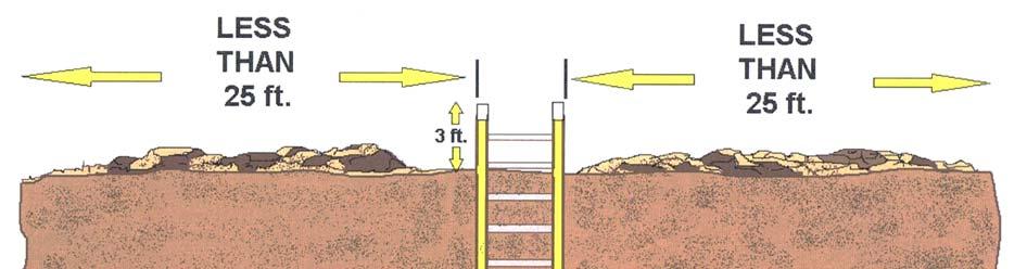
20 Scope of Work 1. During excavation work, a competent person shall be on the job site at all times when personnel are working within or around the excavation. This is necessary in order to monitor soil conditions, equipment and protection systems employed. 2. The estimated locations of utility installations, such as sewer, telephone, fuel, electric, water lines, or any other underground installation that reasonably may be expected to be encountered during excavation work, shall be determined prior to opening an excavation. 3. Adequate precautions shall be taken to protect employees working in excavations, against the hazards posed by water accumulation. 4. Employees shall be protected from excavated or other materials, or equipment, that could pose a hazard by falling or rolling into excavations. Protection shall be provided by placing and keeping such material or equipment at least two (2') feet from the edge of excavations. 5. A stairway, ladder, or ramp shall be used as a means of access or egress in trench excavations that are four (4') feet or more in depth. The ladder(s), stairway(s), or ramp shall be spaced so that no employee in the trench excavation is more than twenty (25') feet from a means of egress. When ladder(s) are employed, the top of the ladder shall extend a minimum of three (3') feet above the ground and shall be properly secured. 6. When excavations are exposed to vehicular traffic, each employee shall wear a warning vest made with reflective material or high visibility material. All personnel within the construction area shall wear a hard-hat at all times. 7. Employees shall not be permitted underneath loads handled by lifting or digging equipment. Employees shall be required to stand away from any vehicle being loaded or unloaded to avoid being struck by any spillage or falling materials. 8. In excavations where oxygen deficiencies or gaseous conditions exist, or could be reasonably expected to exist, air in the excavation shall be tested. 9. Where oxygen deficiencies (atmospheres containing less than 19.5 percent oxygen) exist, the area must be continuously ventilated until the oxygen levels are above 19.5 percent. 10. Where a gaseous condition exists, the area shall be ventilated until the flammable gas concentration is below 20 percent of the lower flammable limit. 11. Whenever oxygen deficiencies or gaseous conditions exist or could reasonably exist, the area shall be monitored continuously to assure that employees are protected. 12. Where the stability of adjoining buildings, walls or other structures are endangered by excavation operations, support systems such as shoring, bracing, or underpinning shall be provided to ensure the stability of such structures for the protection of employees. 13. Sidewalks, pavement and appurtenant structures shall not be undermined unless a support system, such as shoring, is provided to protect employees from the possible collapse of such structures. 20


21 Water Accumulation Employees shall not work in excavations in which there is accumulated water, or in excavations in which water is accumulating, unless adequate precautions have been taken to protect employees against the hazards posed by water accumulation. The precautions necessary to protect employees adequately vary with each situation, but could include special support or shield systems to protect from cave-ins, water removal to control the level of accumulating water, or use of a safety harness and lifeline. Never work in an excavation with accumulating water without proper protection and/or a lifeline and harness to drag your dead body out of the hole. Huge OSHA Violation. 21
22 22
 feet, except when the excavation is within stable rock.")
23 Personnel Protection Systems Employees in excavations shall be protected from cave-ins by an adequate protective system, which shall be inspected by a competent person. The use of protective systems is required for all excavations in excess of five (5') feet, except when the excavation is within stable rock. Trench excavation less than five (5') feet in depth may not require the use of protective systems, unless there is evidence of a potential cave-in. The competent person shall determine the need for the use of protective systems when such conditions exist. When sloping, benching or protective systems are required, refer to requirements in CFR (OSHA Construction Standards). Whenever support systems, shield systems, or other protective systems are being used, a copy of the manufacturer's specifications, recommendations, and limitations sheet shall be in written form and maintained at the job site. How would you make this excavation safe to work inside? The trench is 9 feet deep. OSHA Violations include no hard hats, no ladders, and no daily inspection form. 23

24 24

25 Excavation Protection Systems The three basic protective systems for excavations and trenches are sloping and benching systems, shoring, and shields. The protective systems shall have the capacity to resist without failure all loads that are intended or could reasonably be expected to be applied to or transmitted to the system. Every employee in an excavation shall be protected from cave-ins by an adequate protective system. Exceptions to using protective system: Excavations that are made entirely in stable rock. Excavations that are less than 5 feet deep and declared safe by a competent person. Sloping and Benching Systems There are four options for sloping: Slope to the angle required by the standard for Type C, which is the most unstable soil type. The table provided in Appendix B of the Standard may be used to determine the maximum allowable angle (after determining the soil type). Tabulated data prepared by a registered professional engineer can be utilized. A registered professional engineer can design a sloping plan for a specific job. Sloping and benching systems for excavations five (5) to twenty (20) feet in depth must be constructed under the instruction of a designated competent person. Sloping and benching systems for excavations greater than twenty (20) feet must be designed and stamped by a registered professional engineer. Sloping and benching specifications can be found in Appendix B of the OSHA Standard (Subpart P). Shoring Systems Shoring is another protective system or support system. Shoring utilizes a framework of vertical members (uprights), horizontal members (whales), and cross braces to support the sides of the excavation to prevent a cave-in. Metal hydraulic, mechanical or timber shoring are common examples. Marking the utilities after the trench was dug; it looks like the telephone is very close to the hole. This lady is marking fiber optics in the trench. You can wait an hour or two and save yourself a lot of trouble. Never dig without first obtaining buried utility locations. 25
 Shielding is the third method of providing a safe workplace. Unlike sloping and shoring, shielding does not prevent a cave-in.")
26 The different examples of shoring are found in the OSHA Standard under these appendices: APPENDIX C - Timber Shoring for Trenches APPENDIX D - Aluminum Hydraulic Shoring for Trenches APPENDIX E - Alternatives to Timber Shoring Shield Systems (Trench Boxes) Shielding is the third method of providing a safe workplace. Unlike sloping and shoring, shielding does not prevent a cave-in. Shields are designed to withstand the soil forces caused by a cave-in and protect the employees inside the structure. Most shields consist of two flat, parallel metal walls that are held apart by metal cross braces. Shielding design and construction is not covered in the OSHA Standards. Shields must be certified in design by a registered professional engineer and must have either a registration plate on the shield or registration papers from the manufacturer on file at the jobsite office. ANY REPAIRS OR MODIFICATIONS MUST BE APPROVED BY THE MANUFACTURER. Safety Precautions for Shield Systems Shields must not have any lateral movement when installed. Employees will be protected from cave-ins when entering and exiting the shield (examples - ladder within the shield or a properly sloped ramp at the end). Employees are not allowed in the shield during installation, removal, or during any vertical movement. Shields can be 2 ft. above the bottom of an excavation if they are designed to resist loads at the full depth and if there are no indications of caving under or behind the shield. The shield must extend at least 18 inches above the point where proper sloping begins (the height of the shield must be greater than the depth of the excavation). The open end of the shield must be protected from the exposed excavation wall. The wall must be sloped, shored, or shielded. Engineer designed end plates can be mounted on the ends of the shield to prevent cave-ins. Personal Protective Equipment It is OSHA policy for you to wear a hard hat, safety glasses, and work boots on the jobsite. Because of the hazards involved with excavations, other personal protective equipment may be necessary, depending on the potential hazards present (examples-goggles, gloves, and respiratory equipment). You will see several examples of this rule being broken throughout this manual. 26
 for the construction industry.")
27 Excavation & Trenching Guidelines This section outlines procedures and guidelines for the protection of employees working in and around excavations and trenches. This section requires compliance with OSHA Standards described in Subpart P (CFR ) for the construction industry. Safety compliance is mandatory to ensure employee protection when working in or around excavations. The competent person(s) must be trained in accordance with the OSHA Excavation Standard, and all other programs that may apply (examples Hazard Communication, Confined Space, and Respiratory Protection), and must demonstrate a thorough understanding and knowledge of the programs and the hazards associated. All other employees working in and around the excavation must be trained in the recognition of hazards associated with trenching and excavating. REFERENCES 29 CFR , Subpart P - Excavations Excavation Equipment Manufacturer Safety Procedures 27


28 Trench Shields and Boxes 28
29 Commonly Found Hazards One of the reasons OSHA requires a competent person on-site during excavation & trenching are the numerous potential hazardous that may be encountered or created. These hazards include: Electrocution Gas Explosion Entrapment Struck by equipment Suffocation Hazard Controls Before any work is performed and before any employees enter the excavation, a number of items must be checked and insured: Before any excavation, underground installations must be determined. This can be accomplished by either contacting the local utility companies or the local "one-call' center for the area. All underground utility locations must be documented on the proper forms. All overhead hazards (surface encumbrances) that create a hazard to employees must be removed or supported to eliminate the hazard. If the excavation is to be over 20 feet deep, it must be designed by a registered professional engineer who is registered in the state where work will be performed. Adequate protective systems will be utilized to protect employees. This can be accomplished through sloping, shoring, or shielding. The worksite must be analyzed in order to design adequate protection systems and prevent cave-ins. There must also be an excavation safety plan developed to protect employees. Workers must be supplied with and wear any personal protective equipment deemed necessary to assure their protection. All spoil piles will be stored a minimum of two feet from the sides of the excavation. The spoil pile must not block the safe means of egress. If a trench or excavation is 4 feet or deeper, stairways, ramps, or ladders will be used as a safe means of access and egress. For trenches, the employee must not have to travel any more than 25 feet of lateral travel to reach the stairway, ramp, or ladder. No employee will work in an excavation where water is accumulating unless adequate measures are used to protect the employees. A competent person will inspect all excavations and trenches daily, prior to employee exposure or entry, and after any rainfall, soil change, or any other time needed during the shift. The competent person must take prompt measures to eliminate any and all hazards. Excavations and trenches 4 feet or deeper that have the potential for toxic substances or hazardous atmospheres will be tested at least daily. If the atmosphere is inadequate, protective systems will be utilized. If work is in or around traffic, employees must be supplied with and wear orange reflective vests. Signs and barricades must be utilized to ensure the safety of employees, vehicular traffic, and pedestrians. 29

30 30
31 Excavation Safety Plan An excavation safety plan is required in written form. This plan is to be developed to the level necessary to ensure complete compliance with the OSHA Excavation Safety Standard and state and local safety standards. Excavation safety plan factors: Utilization of the local one-call system. Determination of locations of all underground utilities. Consideration of confined space atmosphere potential. Proper soil protection systems and personal protective equipment and clothing. Determination of soil composition and classification. Determination of surface and subsurface water. Depth of excavation and length of time it will remain open. Proper adherence to all OSHA Standards, this excavation and trenching safety program, and any other coinciding safety programs. 1. Warning system for mobile equipment, methods to help prevent vehicles and equipment from falling in the trench can be accomplished by providing: A. Barricades. B. Hand or mechanical signals. C. Stop logs. D. Grade away from the excavation. All equipment with an obstructed rear view is required to have a back-up alarm or an observer when backing { (b) (4). 2. Hazardous atmospheres, you must limit all exposures to hazardous atmospheres. A. Oxygen deficient is anything less than 19.5 % oxygen. Symptoms will include dizziness, increased heart rate or may experience a buzzing in the ears. B. Normal is 21% oxygen. C. Oxygen enriched atmospheres increase flammability of combustible materials. D. Carbon monoxide causes oxygen starvation and can be fatal at a concentration of 1% for one minute. This is equal to 10,000 PPM. The Threshold Limit Value (TLV) is only 50 PPM. E. If there is a possibility that a hazardous atmosphere exists or could be reasonably expected to exist, test the atmosphere before the employee enters an excavation. Some areas of concern include: digging near gas lines, sewers, landfills and near areas of high traffic. F. Provide respirators or ventilation when needed. All personnel must be fit tested before wearing a respirator and all personnel must be trained how to use ventilation. The use of any respirator by employees will require a written respirator program from the employer { ). A. Ventilate trench if flammable gas exceeds 20 % of the lower flammable limit. B. Test the atmosphere often, this will ensure that the trench remains safe. C. Perform regular maintenance on gas meters. Calibrate and change out filters regularly. 31
32 D. Never enter a hazardous atmosphere to rescue an employee, unless you have been trained in rescue techniques and have proper rescue equipment. More than half the deaths occur while attempting a rescue. 3. Emergency rescue equipment must be available when a hazardous atmosphere exists or could be reasonably expected to exist. A. Respirators must be suitable for the exposure. An air supplied or self-contained breathing apparatus is preferable. B. A harness and lifeline is required when an employee enters bellbottom piers and other deep confined spaces. The lifeline must be attended at all times. Employees entering confined spaces must be trained. { (b) (6) I} Specific requirements for welding in confined spaces { (g) and (b)}. 4. Protection from hazards associated with water accumulation is necessary to prevent cave-ins. A. Methods for controlling accumulated water vary with each situation. B. Employees are not permitted to work in trenches were water accumulation exists. C. Special support system or shield systems may be used to protect employees from caveins. D. Water removal equipment may be used and must be monitored by a competent person to prevent water accumulation. E. Safety harness and lifelines may be used to protect employees. F. Surface water must be diverted and controlled. G. Trenches must be inspected after rain. 5. Stability of adjacent structures to protect employees from cave-ins. A. Support systems such as shoring, bracing, or underpinning must be used to support structures that may be unstable due to excavation operations. B. Excavation below the base or footing of a foundation or wall is not permitted unless: i. A support system is provided to ensure the stability of the structure. ii. The excavation is in stable rock. iii. A registered professional engineer approves the operation. C. Support systems must be provided for sidewalks, pavements and other structures that may be affected by the excavation operations. 6. Protection of employees from loose rock or soil. A. Employees must be protected from being struck by materials falling or rolling from the edge and the face of the trench. B. Spoils and equipment must be set back at least 2 feet from the edge of the trench and/or a retaining device must be installed. 7. Fall protection is required for walkways and bridges over trenches. Other fall protection may also be required. 8. Remotely located excavations shall be backfilled, covered, or barricaded, for example (wells, pits, shafts, etc.) 32
. E. At indications of possible cave-ins (fissures, tension cracks, sloughing, undercutting, water seepage, bulging at the bottom). F. To adjacent areas (spoil piles, structures). G.")
33 Inspections must be made: A. Daily prior to starting work. B. As needed throughout the shift by a competent person. C. After every rainstorm. D. After other hazard increasing occurrences (snowstorm, windstorm, thaw, earthquake, etc.). E. At indications of possible cave-ins (fissures, tension cracks, sloughing, undercutting, water seepage, bulging at the bottom). F. To adjacent areas (spoil piles, structures). G. To protective systems and their components (uprights, wales sheeting, shields hydraulics) before and after use. H. To check for indications of a hazardous or potentially hazardous atmosphere. I. To test the atmosphere if a hazard could reasonably be expected to exist. Remove employees from the trench when there are indications of possible cave-ins, protective system failures, or other potentially hazardous conditions. 33
 A support system, such as underpinning, is provided to ensure the safety of employees and the stability of the structure; or (ii) The excavation is in stable rock; or (iii) A registered")
34 Posing a Hazard Excavation below the level of the base or footing of any foundation or retaining wall that could be reasonably expected to pose a hazard to employees shall not be permitted except when: (i) A support system, such as underpinning, is provided to ensure the safety of employees and the stability of the structure; or (ii) The excavation is in stable rock; or (iii) A registered professional engineer has approved the determination that the structure is sufficiently removed from the excavation so as to be unaffected by the excavation activity; or (iv) A registered professional engineer has approved the determination that such excavation work will not pose a hazard to employees. 34


35 Normal day for an excavation professional, inadequate traffic barricades to crane operation. Be prepared, take the time and be safe. 35
36 36

37 Soil Classification and Identification The OSHA Standards define soil classifications within the Simplified Soil Classification Systems, which consist of four categories: Stable rock, Type A, Type B, and Type C. Stability is greatest in stable rock and decreases through Type A and B to Type C, which is the least stable. Appendix A of the Standard provides soil mechanics terms and types of field tests used to determine soil classifications. Stable rock is defined as natural solid mineral matter that can be excavated with vertical sides and remain intact while exposed. Type A soil is defined as: Cohesive soils with an unconfined compressive strength of 1.5 tons per square foot (TSF) or greater. Cemented soils like caliche and hardpan are considered Type A. Soil is NOT Type A if: It is fissured. The soil is subject to vibration from heavy traffic, pile driving or similar effects. The soil has been previously disturbed. The material is subject to other factors that would require it to be classified as a less stable material. The exclusions for Type A most generally eliminate it from most construction situations. Type B soil is defined as: Cohesive soil with an unconfined compressive strength greater than.5 TSF, but less than 1.5 TSF. Granular cohesion-less soil including angular gravel, silt, silt loam, and sandy loam. The soil has been previously disturbed, except soil classified as Type C soil. Soil that meets the unconfined compressive strength requirements of Type A soil, but is fissured or subject to vibration. Dry rock that is unstable. Type C soil is defined as: Cohesive soil with an unconfined compressive strength of.5 TSF or less. Granular soils including gravel, sand and loamy sand. Submerged soil or soil from which water is freely seeping. Submerged rock that is not stable. Soil Test & Identification The competent person will classify the soil type in accordance with the definitions in Appendix A based on at least one visual and one manual analysis. These tests should be run on freshly excavated samples from the excavation and are designed to determine stability based on a number of criteria: the cohesiveness, the presence of fissures, the presence and amount of water, the unconfined compressive strength, and the duration of exposure, undermining, and the presence of layering, prior excavation and vibration. 37
.")
38 The cohesion tests are based on methods to determine the presence of clay. Clay, silt, and sand are size classifications, with clay being the smallest sized particles, silt intermediate and sand the largest. Clay minerals exhibit good cohesion and plasticity (can be molded). Sand exhibits no elasticity and virtually no cohesion unless surface wetting is present. The degree of cohesiveness and plasticity depend on the amounts of all three types and water. When examining the soil, three questions must be asked: Is the sample granular or cohesive? Is it fissured or non-fissured? What is the unconfined compressive strength measured in TSF? The competent person will perform several tests of the excavation to obtain consistent, supporting data along its depth and length. The soil is subject to change several times within the scope of an excavation and the moisture content will vary with weather and job conditions. The competent person must also determine the level of protection based on what conditions exist at the time of the test, and allow for changing conditions. Granite, would you consider this as solid rock? 38
 Through the revised OSHA regulations (effective March 5, 1990), provisions have been made for the use of four (4) options in design of support systems, shield systems, and other protective")
39 Protective System Requirements ( ) Through the revised OSHA regulations (effective March 5, 1990), provisions have been made for the use of four (4) options in design of support systems, shield systems, and other protective systems, [see , C (1) - (4)]. In addition, Appendixes B, C, and D offer tabulated data and limitations for protective systems including sloping and benching along with the use of timber or aluminum hydraulic shoring systems. Keep in mind that protective systems designed by a registered professional engineer and the use of manufacturer s tabulated data will supersede the use of the OSHA tables. The following will help better explain the use of some protective systems. Sloping and Benching For decades, many excavations have been made using the sloping and/or benching personnel protection method. The concept is simple. Excavate the soil to an angle great enough so that remaining walls cannot fall back into the work area. Benching is simply a stair-step approach to sloping used in cohesive soils, being that the net effect is equal to the required slope for the soil type in which the work takes place. In development of the sloping and benching tables, Federal OSHA consulted soils engineers who designed minimum standards using the soil classification system prescribed in Appendix A to Subpart P. Using the criteria for each soil type, minimum angles were developed for Type A, B, and C soils, or any combination of support or shield systems with sloping are also listed as part of the minimum standards in Appendix B. Complete Rule and further instructions are in the rear of this manual. This is not the correct method to bench a hole. 39
.")
40 Sloping Maximum Allowable Slopes SOIL TYPE SLOPE (H:V) ANGLE( º ) Stable Rock Vertical 90º Type A 3/4 : 1 53º Type B 1 : 1 45º Type C 1 1/2 : 1 34º Maximum Allowable Slope means the steepest incline of an excavation face that is acceptable for the most favorable site conditions as protection against cave-ins and is expressed as the ratio of horizontal distance to vertical rise(h:v). The tables and configurations within Appendix B may be used to a maximum depth of twenty (20') feet deep. Jobs greater than twenty (20') feet in depth require the design of a sloping plan by a registered professional engineer (RPE). If configurations are used for depths less than 20 feet other than those found in Appendix B, they must also be designed by a registered professional engineer. Complete Rule and further instructions are in the rear of this manual. OSHA Violation--No ladders, but the best part is the homemade trench box using waterlines as the cross-braces. Remember, trench boxes and shields are a manufactured and engineered safety device that cannot be modified, especially by the competent person. This box collapsed in the hole. Workers must enter and leave the shield in a protected manner, such as by ladder within the shield or a properly sloped ramp at the end. 40

41 Shoring Systems The word Shoring means a structure such as metal hydraulic, mechanical or timber-shoring system that supports the sides of an excavation and which is designed to prevent cave-ins. The key to this definition is the word "supports". Unlike other protective systems, shoring is meant by design, to exert enough force on the trench walls to prevent a cave-in. As diagramed in the Soil Classification Chapter of this manual, unsupported trench walls have vertical, lateral and angled forces pressing toward the excavation. Through proper employment of a shoring system, loads are placed back within the trench walls. In effect, the trench walls are deceived into "believing" that the excavation never took place. Within the OSHA regulations are Appendixes C and D, with tables and limitations for use of timber shoring and aluminum hydraulic shoring as a support system. Other shoring systems may be used if they are accompanied by tabulated data signed by a registered professional engineer or a specific shoring plan has been developed and signed by a registered professional engineer. Timber Shoring Provisions have been made in Appendix C for the use of hardwood timber shoring systems within different soil classifications. The timber required is a mixed oak or equivalent with a bending strength not less than 850 psi. Manufactured members of equivalent strength may be substituted for wood, but must also be accompanied by tabulated data or a shoring plan developed and signed by a registered professional engineer. Installation of timber shoring shall begin from the top and proceed downward. In turn, removal must begin at the bottom and proceed to the top of the trench. When acquiring timber components, make certain that each piece meets the minimum required bending strength (850 psi) within the OSHA standards. Knots, holes or warping of each component may decrease required strength of individual lengths. Complete Rule and further instructions are in the rear of this manual. 41


42 Carbon dioxide and argon, with specific gravities greater than air, may lie in a tank or manhole for hours or days after opening. Since these gases are colorless and odorless, they pose an immediate hazard to health unless appropriate oxygen measurements and ventilation are adequately carried out. 42

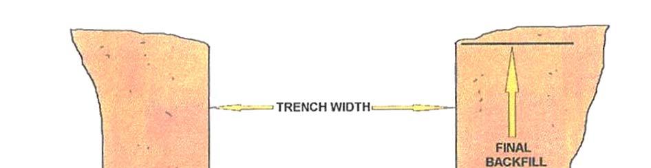
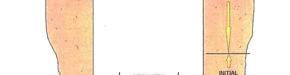
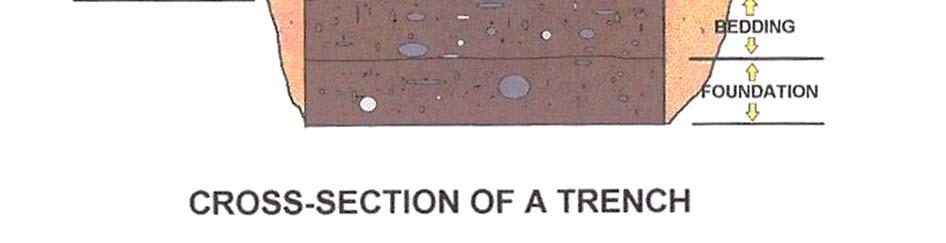
43 Aluminum Hydraulic Shoring Systems Within the current OSHA Standards use Appendix D for the use of aluminum hydraulic shoring systems. In the early 1960's a former military airplane mechanic worked with a utility contractor to develop a more reliable means of shoring trench walls. Using a design incorporating aircraft aluminum alloys (6061-T6) and the use of hydraulic power, a secure method was invented that could often be installed and removed by one person. Installation and removal of aluminum hydraulic shoring takes place while personnel are above the excavation. It is the only shoring system that renders uniform preloading on the trench walls. When the shores are hydraulically activated to the same pressure (psi) shown on the pump gauge, then each cylinder is exerting a uniform axial compressive load on the trench walls. For many types of cohesive soils, the load is dispersed within the trench walls into an arching effect. It is from this arching effect, used in conjunction with the rail strengths, that the horizontal and vertical distance between crossbraces (hydraulic cylinders) is calculated. When using aluminum hydraulic shoring systems, maintain a copy of the manufacturer's tabulated data on the jobsite (see sample within manual). If that data is not available, use the tables in Appendix D of the OSHA excavation standards. Deviation from the specifications, recommendations and limitations issued by the manufacturer, other than the use of Appendix D, shall only be allowed after the manufacturer issues specific written approval. A competent person can use manufacturers' data in the design of an excavation safety plan. Key Definitions EXCAVATION. An Excavation is any man-made cut, cavity, trench, or depression in an earth surface that is formed by earth removal. A Trench is a narrow excavation (in relation to its length) made below the surface of the ground. In general, the depth of a trench is greater than its width, and the width (measured at the bottom) is not greater than 15 ft (4.6 m). If a form or other structure installed or constructed in an excavation reduces the distance between the form and the side of the excavation to 15 ft (4.6 m) or less (measured at the bottom of the excavation), the excavation is also considered to be a trench. HAZARDOUS ATMOSPHERE is an atmosphere that, by reason of being explosive, flammable, poisonous, corrosive, oxidizing, irritating, oxygen-deficient, toxic, or otherwise harmful, may cause death, illness, or injury to persons exposed to it. 43

44 INGRESS AND EGRESS mean "entry" and "exit," respectively. In trenching and excavation operations, they refer to the provision of safe means for employees to enter or exit an excavation or trench. PROTECTIVE SYSTEM refers to a method of protecting employees from cave-ins, from material that could fall or roll from an excavation face or into an excavation, and from the collapse of adjacent structures. Protective systems include support systems, sloping and benching systems, shield systems, and other systems that provide the necessary protection. OSHA Violation. Never utilize bent, cracked, or hydraulic shores as a ladder. Every one of these shores had a serious defect. Bent cross braces are not braces, they are hinges. Any bent or deformed structural member must be repaired or replaced according to the manufacturers guidelines. We like to point out the fact that if an employee is injured or killed, you probably will be charged with a criminal offense as well as an OSHA violation. We have seen criminal fines in the million dollar range with prison sentences to boot. 44
45 Protection of Employees in Excavations I. All employees must be protected from cave-ins, by shields, sloping or shoring except: 1. When the excavations are made in solid rock that is not fractured. 2. Excavations are made less than five (5) feet deep and there is no indication of a possible cave-in as determined by a competent person. a. A competent person is required even when the trench is less than five (5) feet deep. b. Shallow trench cave-ins could be fatal or cause serious injuries. A. Protective systems must have the strength to resist all intended or expected loads. B. Employees must be protected from cave-ins when entering and exiting trenches and shields. C. Employees are not permitted in shields when the shields are being installed, removed or moved vertically. 1. Employees may remain in the shield when the shield is moved horizontally without lifting it. II. Design of sloping and benching systems must be selected and constructed by the employer or his designee when using one or more of the four alternative methods. A. Option 1 Allowable configurations and slopes. 1. Sloped at an angle of 34 degrees = 1½ to Use of other configurations described in Appendix B for Type C soil classifications. B. Option 2 Determination of sloping and benching configurations using Appendices A and B. 1. Soil and rock must be classified. a. Based on site and environmental conditions. b. Based on the composition of the soil. c. Based on acceptable visual and manual tests for classifying soils. Tests are described in Appendix A. 45
46 d. Select sloping or benching configuration from Appendix B based on soil type. C. Option 3 Designs using other tabulated data, such as tables and charts, may be used to select sloping and benching configurations. 1. Identity of the RPE who has approved the data must be stamped on the data. 2. The tabulated data must be in written form, describing detailed information on its use and limitations. 3. Tabulated data must be at the job site during the construction of the protective system. 4. After construction of the protective system, the tabulated data may be kept off-site, but it must be available for inspection. D. Option 4 Sloping and/or benching designs prepared and approved by a RPE may be used. 1. Identity of the RPE who has approved the data must be stamped on the sloping and/or benching designs. 2. Designs must clearly identify the project. 3. The configurations must be determined safe for the project. 4. Design must be at the job site during construction of the sloping and/or benching configuration. 5. After construction of the sloping configuration, the design may be kept off-site, but must be available for inspection. III. IV. Excavations greater than twenty (20) feet in depth must be designed by an RPE and the tabulated data and design must be available for inspection. Design of support systems, shield systems, and other protective systems must be selected and constructed by the employer or his designee using one or more of the alternative methods. A. Option 1 Designs using Appendices A, C, and D may be used by the competent person. 1. Timber shoring is designed by using Appendices A and C. 2. Appendix A and D may be used for hydraulic shoring if the manufacturer s tabulated data is not available or cannot be used. 46
47 B. Option 2 Designs using pre-manufactured protective systems (shoring, shields, or other) and components must be prepared using the manufacturer s tabulated data. 1. Deviations from the use of the manufacturer s specifications must be approved by the manufacturer. 2. Manufacturer s written approval to deviate from the specifications must be on-site during construction of the system. 3. After construction of the system, the written approval may be kept off site, but must be available for inspection. C. Option 3 Designs using other tabulated data, such as tables and charts, may be used to design support systems, shield systems, or other protective systems. 1. There must be enough information necessary to make an accurate selection of the protective system. 2. Identity of the RPE who has approved the data must be stamped on the data. 3. The tabulated data must be in written form, describing detailed information on its use and limitations. 4. Tabulated data must be at the jobsite during construction of the protective system. 5. After construction of the protective system, the tabulated data may be kept off-site, but must be available for inspection. D. Option 4 Protective systems designed and approved by an RPE may be used: 1. The plan must include the size, types, and configurations of the materials to be used. 2. Identity of the RPE who approved the data must be stamped on the sloping and/or benching designs. 3. Designs must identify the project. 4. The design configurations must be determined safe for the project. 5. Design must be at the jobsite during construction of the protective systems. 6. After construction of the protective system, the design may be kept offsite, but must be available for inspection. 47
48 V. Materials and equipment used for protective systems: A. Must be free from damage or defects. B. Must be maintained in good condition. C. Damaged equipment or materials must be inspected by a competent person and removed from use if determined unsafe. D. Once equipment or materials are determined by a competent person to be unsafe, an RPE must evaluate and approve the equipment or materials before returning the equipment to service. VI. Installation and removal of supports. A. Members of the support system securely connected together. B. Employees must be protected from cave-ins and other hazards during installation and removal. C. Members of the support system may not be overloaded. D. Precautions must be taken to prevent cave-ins during removal of structural supports. Removal must start at the bottom. E. Observe structure for indications of failure during removal of support systems. F. Backfill as removal of support systems progress. VII. Additional requirements for support systems for trench excavations: A. Removal of materials to a depth two (2 ) feet below the bottom of the support system is permitted if: 1. The system is designed to resist loads at the full depth of the trench. 2. There are no indications of the possible collapse of soil from behind or below the bottom of the support system. B. Support systems must be installed as the excavation of the trench proceeds. VIII. Sloping and benching systems: A. Employees are not permitted to work on the faces of sloped or benched excavations above other employees unless the employees at the lower levels are protected from being struck by materials or equipment. 48

49 IX. Shield systems (trench boxes) A. Shall not be overloaded. B. Lateral or hazardous movement restricted. C. Employees must be protected from cave-ins when entering and exiting the shields. D. Employees are not permitted in shields during installation, removal, or vertical movement. E. Employees may remain in shield during horizontal movement as long as the shield is not lifted in any way. F. Removal of materials to a depth two (2 ) feet below the bottom of the support system is permitted if: 1. The system is designed to resist loads at the full depth of the trench. 2. There are no indications of possible collapse of soil from behind or below the bottom of the support system. Complete Rule and further instructions are in the rear of this manual. OSHA Violation. It is difficult to see, but this poor soul is inside a death trap. He is in a deep trench sitting in a bell-shaped hole, sitting on a sewer main. He has good shade from a steel plate that is covering the road with cars driving on top. No protection at all. There was a ladder about 50 feet away. Good luck! 49

50 It is OSHA policy for you to wear a hard hat, safety glasses, and work boots on the jobsite. Because of the hazards involved with excavations, other personal protective equipment may be necessary, depending on the potential hazards present (examplesgoggles, gloves, and respiratory equipment). 50
51 Shielding The third method of providing a safe workplace in excavations is shielding. Shielding is different from shoring and sloping in that it does not prevent cave-ins. Instead, it protects the workers in the event of a cave-in. Its function is therefore somewhat similar to that of a bomb shelter. Shields are simply devices that, when placed in an excavation, have sufficient structural strength to support the force of a cave-in should one occur. Shields take a number of different shapes and sizes. Most shields consist of two flat, parallel metal walls which are held apart by metal cross braces which are placed at the ends of the "Box" to allow for the installation of pipe within its interior dimensions. These boxes are used to greatest effect in what is known as "cut and cover" operations, where a contractor excavates just enough trench to install the shield, then sets a joint of pipe, then excavates further, then pulls the shield forward to install another joint while the first is being backfilled. This method is extremely cost-effective, and it is fast, safe, requires minimum excavation and minimum open trench. It has become the preferred method of laying pipe in most instances. While original shields were quite large, smaller shields have gained in popularity with public works maintenance crews and contractors working in shallow excavations because of their ease of use. Recently, round shields, made of corrugated metal have appeared. The sizes, shapes and possibilities for the applications of shields are endless. If they are to be used, however, several points must be borne in mind. 1. Shield construction is not covered by the standard. Users must rely on manufacturers' requirements. For this reason, it is critical that you know your supplier. Reputable manufacturers supply boxes designed by registered professional engineers, and the standard requires that they are certified for their applications. Do not make the mistake of having the neighborhood welder fabricate one. A user must know that their shield is appropriate for the situation. 2. Bent cross braces are not braces, they are hinges. Any bent or deformed structural member must be repaired or replaced according to the manufacturers' guidelines. 3. The manufacturer must approve any modification to the shields. 4. Shields must be installed so as to prevent lateral movement in the event of a cave-in. 5. Shields may ride two feet above the bottom of an excavation, provided they are calculated to support the full depth of the excavation and there is no caving under or behind the shield. 6. Workers must enter and leave the shield in a protected manner, such as by ladder within the shield or a properly sloped ramp at the end. 7. Workers may not remain in the shield during its installation, removal or during vertical movement. 8. Do not forget about the open end of the shield if it exposes a wall of the excavation. The wall should be sloped, shored or shielded off to prevent a cave-in from the end. 9. If the excavation is deeper than the shield is tall, attached shields of the correct specifications may be used or the excavation may be sloped back to maximum allowable angle from a point 18 inches below the top of the shield. Complete Rule and further instructions are in the rear of this manual. 51


52 Various Trench Boxes Daily inspections of excavations, the adjacent areas, and protective systems shall be made by a competent person for evidence of a situation that could result in possible cave-ins, indications of failure of protective systems, hazardous atmospheres, or other hazardous conditions. An inspection shall be conducted by the competent person prior to the start of work and as needed throughout the shift. Inspections shall also be made after every rainstorm or other hazard increasing occurrence. These inspections are only required when employee exposure can be reasonably anticipated. 52

53 Inspections Daily inspection of excavations, the adjacent areas and protective systems shall be made by the competent person for evidence of a situation that could result in a cave-in, indications of failure of protective systems, hazardous atmospheres or other hazardous conditions. All inspections shall be conducted by the competent person prior to the start of work and as needed throughout the shift. Inspections will be made after every rainstorm or any other increasing hazard. All documented inspections will be kept on file in the jobsite safety files and forwarded to the Safety Director weekly. A copy of the Daily Excavation Inspection form is located at the end of this program. The competent person(s) must be trained in accordance with the OSHA Excavation Standard, and all other programs that may apply (examples Hazard Communication, Confined Space, and Respiratory Protection), and must demonstrate a thorough understanding and knowledge of the programs and the hazards associated. All other employees working in and around the excavation must be trained in the recognition of hazards associated with trenching and excavating. Improper shoring storage. Would you trust your life to this equipment? Well, we found one contractor that utilized this equipment. 53


54 What types of dangerous gases are inside this sewer manhole? Who knows unless you have a gas meter. 54
55 Excavation and Confined Space Hazards Flammable Atmospheres A flammable atmosphere generally arises from enriched oxygen atmospheres, vaporization of flammable liquids, byproducts of work, chemical reactions, concentrations of combustible dusts, and desorption of chemicals from inner surfaces of the confined space. An atmosphere becomes flammable when the ratio of oxygen to combustible material in the air is either too rich or too lean for combustion to occur. Combustible gases or vapors will accumulate when there is inadequate ventilation in areas such as a confined space. Flammable gases such as acetylene, butane, propane, hydrogen, methane, natural or manufactured gases or vapors from liquid hydrocarbons can be trapped in confined spaces, and since many gases are heavier than air, they will seek lower levels as in pits, sewers, and various types of storage tanks and vessels. In a closed top tank, it should also be noted that lighter than air gases may rise and develop a flammable concentration if trapped above the opening. The byproducts of work procedures can generate flammable or explosive conditions within a confined space. Specific kinds of work, such as spray painting, can result in the release of explosive gases or vapors. Welding in a confined space is a major cause of explosions in areas that contain combustible gas. Chemical reactions forming flammable atmospheres occur when surfaces are initially exposed to the atmosphere, or when chemicals combine to form flammable gases. This condition arises when dilute sulfuric acid reacts with iron to form hydrogen or when calcium carbide makes contact with water to form acetylene. Other examples of spontaneous chemical reactions that may produce explosions from small amounts of unstable compounds are acetylene-metal compounds, peroxides, and nitrates. In a dry state, these compounds have the potential to explode upon percussion or exposure to increased temperature. Another class of chemical reactions that form flammable atmospheres arises from deposits of pyrophoric substances (carbon, ferrous oxide, ferrous sulfate, iron, etc.) that can be found in tanks used by the chemical and petroleum industry. These tanks containing flammable deposits will spontaneously ignite upon exposure to air. Combustible dust concentrations are usually found during the process of loading, unloading, and conveying grain products, nitrated fertilizers, finely ground chemical products, and any other combustible material. High charges of static electricity, which rapidly accumulate during periods of relatively low humidity (below 50%) can cause certain substances to accumulate electrostatic charges of sufficient energy to produce sparks and ignite a flammable atmosphere. These sparks may also cause explosions when the right air or oxygen to dust or gas mixture is present. 55
56 Toxic Atmospheres The substances to be regarded as toxic in a confined space can cover the entire spectrum of gases, vapors, and finely-divided airborne dust in industry. The sources of toxic atmospheres encountered may arise from the following: 1. The manufacturing process (for example, in producing polyvinyl chloride, hydrogen chloride is used as well as vinyl chloride monomer, which is carcinogenic). 2. The product stored [removing decomposed organic material from a tank can liberate toxic substances, such as hydrogen sulfide (H 2 S)]. 3. The operation performed in the confined space (for example, welding or brazing with metals capable of producing toxic fumes). During loading, unloading, formulation, and production, mechanical and/or human error may also produce toxic gases which are not part of the planned operation. Carbon monoxide (CO) is a hazardous gas that may build up in a confined space. This odorless, colorless gas that has approximately the same density as air is formed from incomplete combustion of organic materials such as wood, coal, gas, oil, and gasoline; it can be formed from microbial decomposition of organic matter in sewers, silos, and fermentation tanks. CO is an insidious toxic gas because of its poor warning properties. Early stages of CO intoxication are nausea and headache. CO may be fatal at 1000 ppm or 10% in air, and is considered dangerous at 200 ppm or 2%, because it forms Carboxyhemoglobin in the blood which prevents the distribution of oxygen in the body. CO is a relatively abundant colorless, odorless gas, therefore, any untested atmosphere must be suspect. It must also be noted that a safe reading on a combustible gas indicator does not ensure that CO is not present. Carbon monoxide must be tested for specifically. The formation of CO may result from chemical reactions or work activities, therefore fatalities due to CO poisoning are not confined to any particular industry. There have been fatal accidents in sewage treatment plants due to decomposition products and lack of ventilation in confined spaces. Another area where CO results as a product of decomposition is in the formation of silo gas in grain storage elevators. In the paint industry, varnish is manufactured by introducing the various ingredients into a kettle, and heating them in an inert atmosphere, usually town gas, which is a mixture of carbon dioxide and nitrogen. In welding operations, oxides of nitrogen and ozone are gases of major toxicological importance; incomplete oxidation may occur and carbon monoxide can form as a byproduct. Another poor work practice, which has led to fatalities, is the recirculation of diesel exhaust emissions. Increased CO levels can be prevented by strict control of the ventilation and the use of catalytic converters. 56

57 Equipment and Injuries If activation of electrical or mechanical equipment would cause injury, each piece of equipment should be manually isolated to prevent inadvertent activation before workers enter or while they work in a confined space. The interplay of hazards associated with a confined space, such as the potential of flammable vapors or gases being present, and the build-up of static charge due to mechanical cleaning, such as abrasive blasting, all influence the precautions which must be taken. 57


58 The primary hazard of trenching and excavation is employee injury from collapse. Soil analysis is important in order to determine appropriate sloping, benching, and shoring. Additional hazards include working with heavy machinery; manual handling of materials; working in proximity to traffic; electrical hazards from overhead and underground power-lines; and underground utilities, such as natural gas. The following references aid in recognizing and controlling some of the hazards associated with trenching and excavation. 58


59 Ensure policies and procedures will be followed when excavating across foreign utilities and other underground structures. Ensure that the competent person is available while any trenching/excavation work is being performed. Ensure that benching, sloping, and shoring practices are followed when necessary. Ensure proper protection and support of existing utilities and structures. 59


60 60

61 61

62 62
63 Irritant (Corrosive) Atmospheres Irritant or corrosive atmospheres can be divided into primary and secondary groups. The primary irritants exert no systemic toxic effects (effects on the entire body). Examples of primary irritants are chlorine, ozone, hydrochloric acid, hydrofluoric acid, sulfuric acid, nitrogen dioxide, ammonia, and sulfur dioxide. A secondary irritant is one that may produce systemic toxic effects in addition to surface irritation. Examples of secondary irritants include benzene, carbon tetrachloride, ethyl chloride, trichloroethane, trichloroethylene, and chloropropene. Irritant gases vary widely among all areas of industrial activity. They can be found in plastics plants, chemical plants, the petroleum industry, tanneries, refrigeration industries, paint manufacturing, and mining operations. Prolonged exposure at irritant or corrosive concentrations in a confined space may produce little or no evidence of irritation. This may result in a general weakening of the defense reflexes from changes in sensitivity. The danger in this situation is that the worker is usually not aware of any increase in his/her exposure to toxic substances. Asphyxiating Atmospheres The normal atmosphere is composed approximately of 20.9% oxygen, 78.1% nitrogen, and 1% argon with small amounts of various other gases. Reduction of oxygen in a confined space may be the result of either consumption or displacement. The consumption of oxygen takes place during combustion of flammable substances, as in welding, heating, cutting, and brazing. A more subtle consumption of oxygen occurs during bacterial action, as in the fermentation process. Oxygen may also be consumed during chemical reactions, as in the formation of rust on the exposed surface of the confined space (iron oxide). The number of people working in a confined space and the amount of their physical activity will also influence the oxygen consumption rate. A second factor in oxygen deficiency is displacement by another gas. Examples of gases that are used to displace air, and therefore reduce the oxygen level are helium, argon, and nitrogen. Carbon dioxide may also be used to displace air and can occur naturally in sewers, storage bins, wells, tunnels, wine vats, and grain elevators. Aside from the natural development of these gases, or their use in the chemical process, certain gases are also used as inerting agents to displace flammable substances and retard pyrophoric reactions. Gases such as nitrogen, argon, helium, and carbon dioxide, are frequently referred to as non-toxic inert gases, but have claimed many lives. The use of nitrogen to inert a confined space has claimed more lives than carbon dioxide. The total displacement of oxygen by nitrogen will cause immediate collapse and death. Carbon dioxide and argon, with specific gravities greater than air, may lie in a tank or manhole for hours or days after opening. Since these gases are colorless and odorless, they pose an immediate hazard to health unless appropriate oxygen measurements and ventilation are adequately carried out. 63
64 Oxygen Deprivation Oxygen deprivation is one form of asphyxiation. While it is desirable to maintain the atmospheric oxygen level at 21% by volume, the body can tolerate deviation from this ideal. When the oxygen level falls to 17%, the first sign of hypoxia is a deterioration of night vision, which is not noticeable until a normal oxygen concentration is restored. Physiologic effects are increased breathing volume and accelerated heartbeat. Between 14-16%, physiologic effects are increased breathing volume, accelerated heartbeat, very poor muscular coordination, rapid fatigue, and intermittent respiration. Between 6-10%, the effects are nausea, vomiting, inability to perform, and unconsciousness. Less than 6%, the effects are spasmodic breathing, convulsive movements, and death in minutes. Mechanical Hazards If activation of electrical or mechanical equipment would cause injury, each piece of equipment should be manually isolated to prevent inadvertent activation before workers enter or while they work in a confined space. The interplay of hazards associated with a confined space, such as the potential of flammable vapors or gases being present, and the build-up of static charge due to mechanical cleaning, such as abrasive blasting, all influence the precautions which must be taken. To prevent vapor leaks, flashbacks, and other hazards, workers should completely isolate the space. To completely isolate a confined space, the closing of valves is not sufficient. All pipes must be physically disconnected or isolation blanks bolted in place. Other special precautions must be taken in cases where flammable liquids or vapors may re-contaminate the confined space. The pipes blanked or disconnected should be inspected and tested for leakage to check the effectiveness of the procedure. Other areas of concern are steam valves, pressure lines, and chemical transfer pipes. A less apparent hazard is the space referred to as a void, such as double walled vessels, which must be given special consideration in blanking off and inerting. Thermal Effects Four factors influence the interchange of heat between people and their environment. They are: (1) air temperature, (2) air velocity, (3) moisture contained in the air, and (4) radiant heat. Because of the nature and design of most confined spaces, moisture content and radiant heat are difficult to control. As the body temperature rises progressively, workers will continue to function until the body temperature reaches approximately 102 o F. When this body temperature is exceeded, the workers are less efficient, and are prone to heat exhaustion, heat cramps, or heat stroke. In a cold environment, certain physiologic mechanisms come into play, which tend to limit heat loss and increase heat production. The most severe strain in cold conditions is chilling of the extremities so that activity is restricted. Special precautions must be taken in cold environments to prevent frostbite, trench foot, and general hypothermia. 64
65 Protective Insulated Clothing Protective insulated clothing for both hot and cold environments will add additional bulk to the worker and must be considered in allowing for movement in the confined space and exit time. Therefore, air temperature of the environment becomes an important consideration when evaluating working conditions in confined spaces. Noise Noise problems are usually intensified in confined spaces because the interior tends to cause sound to reverberate and thus expose the worker to higher sound levels than those found in an open environment. This intensified noise increases the risk of hearing damage to workers, which could result in temporary or permanent loss of hearing. Noise in a confined space which may not be intense enough to cause hearing damage may still disrupt verbal communication with the emergency standby person on the exterior of the confined space. If the workers inside are not able to hear commands or danger signals due to excessive noise, the probability of severe accidents can increase. Vibration Whole body vibration may affect multiple body parts and organs, depending upon the vibration characteristics. Segmental vibration, unlike whole body vibration, appears to be more localized in creating injury to the fingers and hands of workers using tools, such as pneumatic hammers, rotary grinders or other hand tools which cause vibration. Other Hazards Some physical hazards cannot be eliminated because of the nature of the confined space or the work to be performed. These hazards include such items as scaffolding, surface residues, and structural hazards. The use of scaffolding in confined spaces has contributed too many accidents caused by workers or materials falling, improper use of guard rails, and lack of maintenance to ensure worker safety. The choice of material used for scaffolding depends upon the type of work to be performed, the calculated weight to be supported, and the surface on which the scaffolding is placed, and the substance previously stored in the confined space. Surface residues in confined spaces can increase the already hazardous conditions of electrical shock, reaction of incompatible materials, liberation of toxic substances, and bodily injury due to slips and falls. Without protective clothing, additional hazards to health may arise due to surface residues. Structural hazards within a confined space (such as baffles in horizontal tanks, trays in vertical towers, and bends in tunnels), overhead structural members, or scaffolding installed for maintenance constitute physical hazards which are exacerbated by the physical surroundings. In dealing with structural hazards, workers must review and enforce safety precautions to assure safety. 65

66 Abbreviations: PEL - permissible exposure limit: Average concentration that must not be exceeded during 8-hour work shift of a 40-hour workweek. STEL - Short-term exposure limit: 15-minute exposure limit that must not be exceeded during the workday. REL - Recommended exposure limit: Average concentration limit recommended for up to a 10-hour workday during a 40-hour workweek. IDLH - Immediately dangerous to life or health: Maximum concentration from which person could escape (in event of respirator failure) without permanent or escapeimpairing effects within 30 minutes. Gas Meter, most competent persons will have two meters in case one fails. Where oxygen deficiency (atmospheres containing less than 19.5 percent oxygen) or a hazardous atmosphere exists or could reasonably be expected to exist, such as in excavations in landfill areas or excavations in areas where hazardous substances are stored nearby, the atmospheres in the excavation shall be tested before employees enter excavations greater than 4 feet (1.22 m) in depth. (ii) Adequate precautions shall be taken to prevent employee exposure to atmospheres containing less than 19.5 percent oxygen and other hazardous atmospheres. These precautions include providing proper respiratory protection or ventilation in accordance with subparts D and E of this part respectively. (iii) Adequate precaution shall be taken such as providing ventilation, to prevent employee exposure to an atmosphere containing a concentration of a flammable gas in excess of 20 percent of the lower flammable limit of the gas. 66


67 One-call Center or Bluestakes You are required to locate or call for proper buried utility locations before you dig or excavate. You will usually need a 48-hour notice before you excavate. Please check your local One- Call system. Red spray marks-electricity, Yellow-Gas, Blue-Water. Orange spray marks - Telephone & Fiber Optics. 67

68 One-Call Program According to federal safety statistics, damage from unauthorized digging is the major cause of natural gas pipeline failures. To prevent excavation damage to all utilities, including pipelines, all 50 states have instituted "One-Call" Programs. The programs provide telephone numbers for excavation contractors to call before excavation begins. The One-Call operator will notify a pipeline company of any planned excavation in the vicinity of its pipeline so that the company can flag the location of the pipeline and assign personnel to be present during excavation, if necessary. In a related effort, a joint government-industry team has developed a public education program entitled "Dig Safely". The team involved representatives from the U.S. Department of Transportation, gas and liquid pipeline companies, distribution companies, excavators, the insurance industry, one-call systems and the telecommunications industry. This campaign provides information to the general public concerning underground utilities and the danger of unknowingly digging into buried lines and cables. The program has posters, brochures and other printed materials available for use by interested organizations. For more information, contact Example of buried telephone cables 68
69 Mission of the One-Call Center One-Call Centers were established as a one-call notification system by underground facility owners to assist excavators with statutory requirements to notify underground facility owners prior to excavation. This damage prevention service is provided free of charge to any individual or company planning to excavate. By participating in the program and getting underground facilities located, you can: Comply with Federal Law Avoid Injuries Prevent costly damages and interruptions of facility services Save time and money Avoid hazards Eliminate construction delays Color Codes for marking underground utility lines. Red Yellow Orange Blue Green Pink Electric Power Gas-Oil- Product Lines Communication, Cable television Water systems, slurry pipelines Sanitary sewer system Temporary survey markings Example of a One-Call Center s Rules Excavations: determining location of underground facilities; providing information; excavator marking; on-site representative; validity period of markings. A. A person shall not make or begin any excavation in any public street, alley, right-of-way dedicated to the public use or utility easement or on any express or implied private property utility easement without first determining whether underground facilities will be encountered, and, if so, where they are located from each and every public utility, municipal corporation or other person having the right to bury such underground facilities within the public street, alley, right-of-way or utility easement and taking measures for control of the facilities in a careful and prudent manner. B. Every public utility, municipal corporation or other person having the right to bury underground facilities shall file with the corporation commission the job title, address and telephone number of the person or persons from whom the necessary information may be obtained. Such person or persons shall be readily available during established business hours. The information on file shall also include the name, address and telephone number of each one-call notification center to which the owner of the facility belongs. Upon receipt of inquiry or notice from the excavator, the owner of the facility shall respond as promptly 69
70 as practical, but in no event later than two days, by marking such facility with stakes, paint or in some customary manner. No person shall begin excavating before the location and marking are complete or the excavator is notified that marking is unnecessary. C. On a timely request by the owner of a facility, the excavator shall mark the boundaries of the location requested to be excavated in accordance with a color code designated by the commission or by applicable custom or standard in the industry. A request under this subsection for excavator marking does not alter any other requirement of this section. D. In performing the marking required by subsection B of this section, the owner of an underground facility installed after December 31, 1988 in a public street, alley or right-of way dedicated to public use, but not including any express or implied private property utility easement, shall locate the facility by referring to installation records of the facility and utilizing one of the following methods: 1. Vertical line or facility markers. 2. Locator strip or locator wire. 3. Signs or permanent markers. 4. Electronic or magnetic location or tracing techniques. 5. Electronic or magnetic sensors or markers. 6. Metal sensors or sensing techniques. 7. Sonar techniques. 8. Underground electrical or radio transmitters. 9. Manual location techniques, including pot-holing. 10. Surface extensions of underground facilities. 11. Any other surface or subsurface location technique at least as accurate as the other marking methods in this subsection not prohibited by the commission or by federal or state law. E. For an underground facility other than one installed after December 31, 1988, in a public street, alley or right-of-way dedicated to public use, in performing the marking required by subsection B of this section, the owner may refer to installation or other records relating to the facility to assist in locating the facility and shall locate the facility utilizing one of the methods listed under subsection D of this section. If an underground facility owner is unable to complete the location and marking within the time period provided by subsection B of this section, the facility owner shall satisfy the requirements of this section by proving prompt notice of these facts to the excavator. An assigning one or more representatives to be present on the excavation site at all pertinent times as requested by the excavator to provide facility location services until the facilities have been located and marked. The underground facility owner shall bear all of its costs associated with assigning representatives. If representatives are assigned under this subsection, the excavator is not responsible or liable for damage or repair of the owner s underground facility while acting under the direction of an assigned representative of the owner, unless the damage or need for repair was caused by the excavator s negligence. 70
71 General Gas Safety That familiar blue flame that plays such an important role in our lives should, like other sources of energy, be treated with respect. Following a few simple guidelines can help ensure that you can safely enjoy all the benefits natural gas has to offer. Natural gas is colorless and invisible. When it burns it should appear as a clear, blue flame. Because natural gas has no odor, a special chemical called mercaptan is added to make it easy to detect gas leaks from pipes or appliances. This odor is commonly described as a rotten egg smell. Natural gas is clean-burning. When burned completely, it produces only water vapor and carbon dioxide - just as you do when you breathe. Natural gas is such a safe and dependable fuel that it's easy to take for granted. But please, never take safety for granted. As with any source of energy, you should follow certain safety measures when using natural gas. When it's taken from the ground, natural gas is tasteless, colorless and odorless. To make it easier to detect, a harmless but strong-smelling odorant is added. If you ever smell this "rotten egg-like" odor, it may mean there is a gas leak. WHAT TO DO IF YOU SMELL GAS: Do not smoke. Do not use lighters or matches. Do not turn on/off any switches or appliances. Our personnel are available 24 hours a day to respond to any emergency call. Carbon Monoxide Carbon monoxide is produced when burning any fuel incompletely, such as charcoal, gasoline or wood. Carbon monoxide is highly poisonous and it has no odor, taste or color. If natural gas equipment is not maintained, adjusted and operated properly, it could produce carbon monoxide. Your natural gas appliances should produce a clear, steady blue flame. If your gas appliances exhibit an unusual behavior or produce a yellowish-color flame, it may be a warning sign that your appliance is producing carbon monoxide. A licensed professional should inspect appliances annually to insure safe operation. An inspection will accomplish the following: Make sure the appliance is installed properly and that it is in good working condition. Ensure that there is enough fresh air circulating for the fuel to burn properly. Check that vents are in good condition and are not blocked with debris. Other helpful tips: The area surrounding your gas appliances should be clear from clutter or trash. Carbon monoxide detectors may be helpful in your home or business. But remember, a carbon monoxide detector should never be substituted for using equipment safely - which includes having your heating and cooking equipment inspected once a year by a trained professional. 71

72 Unsafe ladder storage. 72

73 Soil Classification Section This appendix describes methods of classifying soils based on site and environmental conditions. The standard requires that visual and manual tests be performed to classify soils. A competent person must complete the tests. The classifications are used when designing sloping and benching systems, designing timber and aluminum hydraulic shoring systems, and selecting trench shields. Unconfined compressive strength is the load per unit area that will cause the soil to fail in compression. Unconfined compressive strength can be determined by using a pocket penetrometer, Shearvane (shear test), and thumb penetration test. OSHA recognizes three types of soil: Type A: Cohesive soils with an unconfined compressive strength of 1.5 ton per square foot (TSF) or greater. Examples: clay, silty clay, sandy clay, clay loam, hardpan, and cemented soils. No soil will be considered Type A if the following: soil is fissured, subject to vibration, was previously disturbed, is part of a layered system, sloping into the trench, or is seeping water. Type B: Cohesive soil with an unconfined compressive strength greater than 0.5 TSF but less than 1.5 TSF. Examples: angular gravel, silt, silt loam, previously disturbed soils unless otherwise classified, dry unstable rock, some layered systems. Type C: Cohesive soil with an unconfined compressive strength of 0.5 TSF or less. Examples: granular soils, sand, loamy sand, submerged, soil with freely seeping water, any soil not otherwise classified. Field tests that can be used to classify cohesive and non-cohesive soils include: sedimentation test, wet shake test, dry strength test, thin thread test and the ribbon test. Thumb Test 73
74 APPENDIX B Sloping and Benching Provides the required specifications for sloping and benching based on the soil type "A", "B", "C". APPENDIX C TIMBER SHORING FOR TRENCHES Provides information that can be used when designing timber shoring based on the soil type. The tables present minimum sizes of timber members to use in a shoring system. Each table contains information only for a particular soil type. These shoring specifications do not necessarily apply to all the different situations that may be encountered. They apply to situations that are most commonly found. APPENDIX D ALUMINUM HYDRAULIC SHORING FOR TRENCHES Provides information that can be used when designing aluminum hydraulic shoring for trenches that do not exceed twenty feet (20') in depth. Each table presents the maximum vertical and horizontal spacing that may be used with various size aluminum-shoring components. The members of the shoring systems that are selected from these tables are the hydraulic cylinder, and either the vertical shores or the horizontal wales. APPENDIX E ALTERNATIVES TO TIMBER SHORING Provides information about alternatives to using timber or aluminum hydraulic shoring systems. APPENDIX F SELECTION OF PROTECTIVE SYSTEMS A graphic summary of the requirements provided in Subpart P is provided for trenches less than twenty feet (20') deep. Complete Rule and further instructions are in the rear of this manual. 74

75 Compressive Strength Testing Pocket Penetrometer is a direct reading device that is used to determine the approximate unconfined compressive strength of saturated cohesive soils. The spring-operated device uses a piston that is pushed into a soil up to a calibration grove. An indicator sleeve marks and retains the reading until the operator attains the reading. The reading is calibrated in tons per square feet (TSF) or kilograms per cubic centimeter. An adapter foot is available for soft soils. Always follow the manufacturer's instructions. Pocket Penetrometer Type-A Soil The most stable and cohesive type of soil while working at a trench site. Examples are clay, silty clay and hardpan. Type-B Soil Type-B soil is next to the most stable soil. Silt, silt loam, sandy loam, medium clay and unstable rock would be good examples of Type-B soils. Type-C Soil The least stable type of soil. Examples of Type-C soils are gravel, loamy sand, soft clay, submerged silt and heavy unstable rock. Unconfined Compressive Strength Through a variety of tests, a soil s strength is found, the unconfined compressive strength is the soil s measure of bearing capacity and shearing resistance. Measured as the amount of weight per square foot needed to collapse a soil sample. 75

76 Shearvane (Torvane) measures the approximate shear strength of saturated cohesive soils. The blades of the vane are pressed into a flat section of undisturbed soil, and the knob is turned slowly until soil failure. The dial is read directly when using the standard vane. The reading is calibrated in kilograms per cubic centimeter. This reading can be converted to the approximate unconfined compressive strength by multiplying by a factor of two. The result will be in tons per square foot or kilograms per cubic centimeter. Always follow the manufacturer s instructions. Thumb Penetration Test is the least accurate of all the tests; however it is an acceptable method of determining approximate unconfined compressive strength of soils. It relies heavily on the experience of the person performing the test. "Type A" soils can be readily indented by the thumb but they can only be penetrated with great difficulty. "Type C" soils can be easily penetrated by the thumb and can be molded by light finger pressure. Dry Strength Test is used to roughly determine the shear strength of a soil. If the soil is dry and crumbles without much effort the soil is granular (gravel, sand, or silt). If the soil is dry and falls apart into clumps that break up into smaller clumps, but the smaller clumps can only be broken up with difficulty, it may be clay in any combination with gravel, sand or silt. If it breaks into clumps that do not break into smaller clumps and which can only be broken with difficulty, and there is no indication that the soil is fissured, the soil may be considered unfissured. 76


77 Ribbon Test is used to determine how much clay or silt the soil contains. This test is generally run on soil that passes the #41 sieve. The saturated fine soil and fine sands are rolled together between the palms of the hands until a cylinder approximately ¾ inch thick by approximately 6 inches long is formed. The cylinder is then placed across the palm of the hand and squeezed between the thumb and index finger until it is approximately 1/8 inch thick. The squeezed portion is allowed to hang over the side of the hand. If it forms ribbons 6 inches in length or longer, it is said to be clay. The longer the ribbon, the more clay the soil may contain. If it forms shorter broken ribbons, then the soil contains silt. A clay loam will barely form a ribbon. Thread Test is used to determine if a soil is cohesive. A moist sample of soil is rolled into a ball and then rolled into a thread between the palms. A thin thread approximately 1/8 inch thick by 2 inches or more in length is formed. The soil is considered to be cohesive if a 2-inch or longer piece can be held by one end without breaking. Wet Shake Test is used for estimating a soil's plasticity. After removing gravel and coarse sand, add enough water to mold the sample into a ball that is soft but not sticky. The molded sample should be approximately ¾ inch in diameter. The sample is placed in the palm of the hand and shaken horizontally or struck with the other hand. If water comes to the surface, the sample becomes shiny. The sample is then deformed by folding the palm of the hand. If the water is absorbed into the sample and the surface becomes dull, then the soil is sand, silt, or a combination. Fine sands react quickly to this test. Silt will react more slowly. Clays will not become shiny and will not react to this test. Sedimentation test is used to determine the approximate amount of sand in a soil. This procedure can also be used to estimate the percentage of silt and clay in a soil. For our purposes, we will use it to estimate the percentage of granular and fine materials in a field sample. A straightsided jar or a flask 6 inches or more in height with a flat bottom is required (an olive jar can be used). After removing granular materials larger than 2 millimeters (#10 sieve) be sure to break up all clumps of fine materials. Place approximately 1½ inches of soil sample in the jar and then fill with water. 77


78 Shake until all the materials in the jar are suspended in water. Quickly set the jar on a flat surface and give it a quick half turn. After thirty seconds, place a mark at the top of the settled sand. After one minute, mark the settled material again. The material between these two marks is mostly silt. Wait one hour and mark the top of the settled soil. The material between the top of the silt and the top of the settled soil will be mostly clay. Measure the height of the mark for the settled sand and divide by the height of the mark for the settled sample and multiply by 100. This calculation will provide the approximate percentage of sand in the soil. The distance between the top of the sand mark and the top of the silt divided by the total height of the settled sample multiplied by 100 is the percentage of silt. The amount of clay can also be measured and divided by the total height of the sample and multiplied by100 to determine its percentage. Using the triangular classification chart of the Textural Classification System and the approximate percentages of sand, silt and clay, the texture of the soil can be determined. 78
79 DAILY EXCAVATION CHECKLIST EXAMPLE Client Project Name Project Location Job Number Excavation Depth & Width Protective System Used Activities In Excavation Competent Person Date Approx. Temp. Approx. Wind Dir. Safety Rep Soil Classification Excavation > 4 feet deep? Yes No If YES, fill out a Confined Space Permit PRIOR to ANY person entering the excavation. NOTE: Trenches over 4 feet in depth are considered excavations. Any items marked NO on this form MUST be remediated prior to any employees entering the excavation. YES NO N/A DESCRIPTION GENERAL Employees protected from cave-ins & loose rock/soil that could roll into the excavation. Spoils, materials & equipment set back at least 2 feet from the edge of the excavation. Engineering designs for sheeting &/or manufacturer's data on trench box capabilities on site. Adequate signs posted and barricades provided. Training (toolbox meeting) conducted w/ employees prior to entering excavation. UTILITIES Utility company contacted & given 24 hours notice &/or utilities already located & marked. Overhead lines located, noted and reviewed with the operator. Utility locations reviewed with the operator, & precautions taken to ensure contact does not occur. Utilities crossing the excavation supported, and protected from falling materials. Underground installations protected, supported or removed when excavation is open. WET CONDITIONS Precautions taken to protect employees from water accumulation (continuous dewatering). Surface water or runoff diverted /controlled to prevent accumulation in the excavation. Inspection made after every rainstorm or other hazard increasing occurrence. 79

80 HAZARDOUS ATMOSPHERES Air in the excavation tested for oxygen deficiency, combustibles, and other contaminants. Ventilation used in atmospheres that are oxygen rich/deficient &/or contains hazardous substances. Ventilation provided to keep LEL below 10 %. Emergency equipment available where hazardous atmospheres could or do exist. Safety harness and lifeline used. Supplied air necessary (if yes, contact safety department). ENTRY & EXIT Exit (i.e. ladder, sloped wall) no further than 25 feet from ANY employee. Ladders secured and extend 3 feet above the edge of the trench. Wood ramps constructed of uniform material thickness, cleated the bottom. Employees protected from cave-ins when entering or exiting the excavation. KEEP 1 COPY OF EACH DAILY EXCAVATION CHECKLIST ON SITE FOR THE PROJECT DURATION, AND FORWARD THE ORIGINAL TO THE SAFETY DIRECTOR 80

81 Handling an OSHA Inspection Sometimes when an OSHA Compliance Officer visits a job site, project managers, foremen, competent persons feel intimidated. In order to avoid this, companies should have a company policy and a plan of action for managers to follow when handling an OSHA inspection. It is important to remember that in order to defend your company against alleged violations at an OSHA hearing or in a court of law accurate documentation is necessary so that the facts are not forgotten. All competent persons should keep a logbook to help them remember the dates, temperature, conditions, trench, address, and the crew that was working. This along with your daily excavation inspection report will help defend your job decisions. You should keep a copy of the OSHA construction standards, your safety policy, and a copy of your written hazard communication policy with you at all times. If OSHA shows up to your job site Do not volunteer any information. Record the name and badge number of the OSHA compliance officer. Fill out the OSHA Inspection Report at the time of the inspection. Ask the OSHA Inspector to wait while you contact the main office. You may also have him wait a reasonable amount of time until someone comes from the main office to accompany him on the inspection. If the inspector will not wait, note his answer on the OSHA Inspection Report and remain with the inspector. Take notes on whatever he says or does. Take pictures of whatever he takes pictures of and take soil samples from wherever he takes soil samples After the inspector leaves the job site, telephone the main office and report the results of the inspection to the safety manger. Make sure the OSHA Inspection Report is complete and send it along with copies of your notes and pictures to the safety manger. Actual OSHA Inspector inspecting a respirator and then checking the training record. 81


82 The OSHA Compliance Officer: Cannot require you to demonstrate anything for his viewing. Does not have the authority to take any written materials from your job sites that belong to your company. Does not have control of your employees or jobsite. The OSHA Compliance Officer is a guest on the jobsite. He should be treated with respect, not fear. Do not admit guilt to any violation. OSHA Inspection Inspectors will ask employees several different questions from CPR training, LOTO, Bloodborne Pathogen to HazCom and RP. He will also require training records to prove that you have been trained. He will also carry several specialized safety tools to inspect all kinds of tools and devices. 82
83 OSHA Inspection Report Example DATE: TIME: WEATHER: ADRESS: NAME OF COMPANY: NAME OF COMPETENT PERSON: DID OSHA INSPECTOR WAIT FOR A MANAGER? YES NO HOW LONG? WAS AN OPENING CONFERENCE HELD? DEPTH OF TRENCH: WIDTH: WATER PRESENT: TYPE OF SOIL: A,B,C TYPE OF SOIL TEST TAKEN: EMPLOYEE'S IN TRENCH? HARD HATS BEING WORN? SAFETY VESTS, SAFETY HARNESS, GAS METER PRESENT? CURRENT COMPETENT PERSON JOBSITE INSPECTION REPORT: WAS TRENCH: SLOPED WHAT ANGLE SHORED OUR SYSTEM WATER PRESENT: CONTROLLED: OTHER: LADDER: SECURED: CONFINED SPACE: ATMOSPHERIC READINGS: PROPER BARRICADES AND SIGNAGE PRESENT: ARE ALL EMPLOYEES CURRENT CPR, CONFINED SPACE, COMPETENT PERSON CERTIFIED? HAZARD COMMUNICATION PROGRAM: RISK MANAGEMENT: COMMENTS: WHERE PHOTOGRAPHS TAKEN: SIGNAGURE: TITLE: TELEPHONE NUMBER: DATE: OTHER AGENCIES NOTIFIED? 83
84 OSHA Construction Visits During first and subsequent visits to a construction or facility maintenance location, the compliance officer (or the site's safety officer or other competent person) may find the following questions useful. 1. Is the cut, cavity, or depression a trench or an excavation? 2. Is the cut, cavity, or depression more than 4 ft (1.2 m) in depth? 3. Is there water in the cut, cavity, or depression? 4. Are there adequate means of access and egress? 5. Are there any surface encumbrances? 6. Is there exposure to vehicular traffic? 7. Are adjacent structures stabilized? 8. Does mobile equipment have a warning system? 9. Is a competent person in charge of the operation? 10. Is equipment operating in or around the cut, cavity, or depression? 11. Are procedures required to monitor, test, and control hazardous atmospheres? 12. Does a competent person determine soil type? Was a soil testing device used to determine soil type? 13. Is the spoil placed 2 ft (0.6 m) or more from the edge of the cut, cavity, or depression? 14. Is the depth 20 ft (6.1 m) or more for the cut, cavity, or depression? 15. Has a registered professional engineer approved the procedure if the depth is more than 20 ft (6.1 m)? 16. Does the procedure require benching or multiple benching? Shoring? Shielding? 17. If provided, do shields extend at least 18 in (0.5 m) above the surrounding area if it is sloped toward the excavation? 18. If shields are used, is the depth of the cut more than 2 ft (0.6 m) below the bottom of the shield? 19. Are any required surface crossings of the cut, cavity, or depression the proper width and fitted with hand rails? 20. Are means of egress from the cut, cavity, or depression no more than 25 ft (7.6m) from the work? 21. Is emergency rescue equipment required? 84
85 Ladder Safety Section Purpose Ladders present unique opportunities for unsafe acts and unsafe conditions. Employees who use ladders must be trained in proper selection, inspection, use and storage. Improper use of ladders has caused a large percentage of accidents in the workplace. Use caution on ladders. OSHA reference: (29 CFR , , and ). Ladder Hazards Falls from ladders can result in broken bones and/or death. Ladder safety is a lifesaving program at our company/facility/department. Hazards include: Ladders with missing or broken parts. Using a ladder with too low a weight rating. Using a ladder that is too short for purpose. Using metal ladders near electrical wires. Using ladders as a working platform. Objects falling from ladders. Ladder Inspection Inspect ladders before each use. All rungs and steps are free of oil, grease, dirt, etc. All fittings are tight. Spreaders or other locking devices are in place. Non-skid safety feet are in place. No structural defects, all support braces intact. Do not use broken ladders. Most ladders cannot be repaired to manufacturer specifications. Throw away all broken ladders. Ladder Storage Store ladders on sturdy hooks in areas where they cannot be damaged. Store ladders to prevent warping or sagging. Do not hang anything on ladders that are in a stored condition. Ladder Ratings & Limits Ladder weight ratings I-A 300 pounds (heavy duty) I 250 pounds (heavy duty) II 225 pounds (medium duty) III 200 pounds (light duty). 85

86 Limits on ladder length. A stepladder should be no more than 20 feet high. A one-section ladder should be no more than 30 feet. An extension ladder can go to 60 feet, but the sections must overlap. Ladder Setup The following procedure must be followed to prevent ladder accidents: Place ladder on a clean slip free level surface. Extend the ladder to have about 4 feet above the top support or work area. Anchor the top and bottom of the ladder. Place the ladder base 1/4 the height, of the ladder, from the wall when using an extension ladder. Never allow more than one person on a ladder. Use carriers and tool belts to carry objects up a ladder. Do not lean out from the ladder in any direction. If you have a fear of heights - don't climb a ladder. Do not allow others to work under a ladder in use. Ladder Maintenance Keep ladders clean. Never replace broken parts unless provided by the original manufacturer. Do not attempt to repair broken side rails. Four most common OSHA violations that we found during our research were: No Daily Inspection form, no hard hats or PPE, no soil testing and we only found one proper ladder installation after visiting over 50 sites. 86


87 Confined Space Section Confined Spaces Many workplaces contain spaces that are considered "confined" because their configurations hinder the activities of any employees who must enter, work in, and exit them. For example, employees who work in process vessels generally must squeeze in and out through narrow openings and perform their tasks while cramped or contorted. OSHA uses the term "confined space" to describe such spaces. In addition, there are many instances where employees who work in confined spaces face increased risk of exposure to serious hazards. In some cases, confinement itself poses entrapment hazards. In other cases, confined space work keeps employees closer to hazards, such as asphyxiating atmospheres or the moving parts of machinery. OSHA uses the term "permit-required confined space" (permit space) to describe those spaces that both meet the definition of "confined space" and pose health or safety hazards. For more information about Confined Space, please refer to TLC s Confined Space Course. 87
88 Confined Spaces are -large enough to allow entry of any body part, and -limited or restricted entry or exit, and -not designed for continuous employee occupancy. Permit Required Confined Spaces are confined spaces that have any of the following -potential hazardous atmosphere -material inside that may engulf or trap you -internal design that could trap or asphyxiate you -any other serious safety or health hazard Entry Permits are required before you enter any Permit Required Confined Space Hazards include Fire & Explosion Engulfment Asphyxiation Entrapment Slips & Falls Electric Shock Noise & Vibration Chemical Exposure Toxic Atmospheres Thermal / Chemical Burns Engineering Controls Ventilation Locked Access Lighting Administrative Controls Controlled Access Hazard Assessments Entry Permits & Procedures Signs & Lockout Tagout Training Smart Safety Rules Know what you are getting into. Know how to get out in an emergency. Know the hazards & how they are controlled. Only authorized & trained personnel may enter a confined space or act as an attendant. No smoking in confined space or near entrance or exit area. Attendant must be present at all times. Constant visual or voice communication must be maintained between the attendant and entrants. No bottom or side entry will be made, or work conducted, below the level of any hanging material or material which could cause engulfment. Air and oxygen monitoring is required before entering a permit-required confined space. Ventilation & oxygen monitoring is required when welding is performed. 88

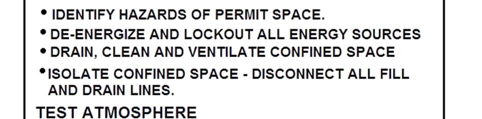

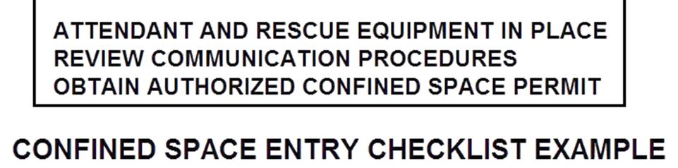
89 89
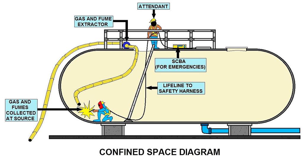

90 90

91 Confined Space - Defined Purpose The Confined Space Entry Program is provided to protect authorized employees that will enter confined spaces and may be exposed to hazardous atmospheres, engulfment in materials, conditions which may trap or asphyxiate due to converging or sloping walls, or contains any other safety or health hazards. Reference: OSHA-Permit-Required Confined Spaces (29 CFR ). Scope You are required to recognize the dangers and hazards associated with confined spaces, and this program is designed to assist you in the safety of and compliance with the OSHA standards associated with such. Most communities will utilize the fire department for all rescues and additional assistance dealing with confined spaces, understanding that most fire department operations utilize additional in house SOG's pertaining to such operations. Definitions Confined space: Is large enough or so configured that an employee can bodily enter and perform work. Has limited or restricted means for entry or exit (i.e. tanks, vessels, silos, storage bins, hoppers, vaults, and pits are spaces that may have limited means of entry). Is not designed for continuous employee occupancy. Permit required confined space (permit space), is a confined space that has one or more of the following characteristics: 1. Contains or has a potential to contain a hazardous atmosphere. 2. Contains a material that has the potential for engulfing an entrant. 3. Has an internal configuration such that an entrant could be trapped or asphyxiated by inwardly covering walls or by a floor which slopes downward and tapers to a smaller crosssection. 4. Contains any other recognized serious safety or health hazard. Each Permit-Required Confined Space will be marked "Confined Space - Entry Permit Required". 91
92 Confined Space Permitted Confined Space Entry Program Definition of Confined Spaces Requiring an Entry Permit A Confined space: 1. Is large enough or so configured that an employee can bodily enter and perform work. 2. Has limited or restricted means for entry or exit (i.e. tanks, vessels, silos, storage bins, hoppers, vaults, and pits are spaces that may have limited means of entry). 3. Is not designed for continuous employee occupancy. Purpose The Permit Required Space (PRCS) Program is provided to protect authorized employees that will enter confined spaces and may be exposed to hazardous atmospheres, engulfment in materials, conditions which may trap or asphyxiate due to converging or sloping walls, or contains any other safety or health hazards. Many workplaces contain confined spaces not designed for human occupancy which, due to their configuration, hinder employee activities including entry, work and exit. Asphyxiation is the leading cause of death in confined spaces. Subpart P applies to all open excavations in the earth's surface. All trenches are excavations. All excavations are not trenches. Permit Required Confined Space Entry General Rules During all confined space entries, the following safety rules must be strictly enforced: 1. Only authorized and trained employees may enter a confined space or act as safety watchmen. 2. No smoking is permitted in a confined space or near entrance/exit area. 3. During confined space entries, a watchman must be present at all times. 4. Constant visual or voice communication will be maintained between the safety watchmen and employees entering a confined space. 5. No bottom or side entry will be made, or work conducted, below the level of any hanging material or material which could cause engulfment. 6. Air and oxygen monitoring is required before entering any permit-required confined space. Oxygen levels in a confined space must be between 19.5 and 23.5 percent. Levels above or below will require the use of an SCBA or other approved air supplied respirator. Additional ventilation and oxygen level monitoring is required when welding is performed. The monitoring will check oxygen levels, explosive gas levels and carbon monoxide levels. Entry will not be permitted if explosive gas is detected above one-half the Lower Explosive Limit (LEL). 7. To prevent injuries to others, all openings to confined spaces will be protected by a barricade when covers are removed. 92
93 Confined Space Entry Permit Example Date & Time Issued Space I.D. Equipment Affected Standby Team Pre-Entry Atmospheric Checks Time (am - pm) Date & time Expires Supervisor Task Oxygen Explosive ( % LEL) Toxic (PPM) Testers Signature Pre-entry Fluid System Isolation Yes No Pumps /lines blinded, blocked, disconnected Ventilation Source Established Mechanical Forced Air Natural Ventilation Post Ventilation Pre-Entry Atmospheric Checks Time Oxygen (%) Explosive ( % LEL Toxic (PPM) Tester Signature Communication Procedures Established per specific Confined Space SOP Rescue Procedures established per specific Confined Space SOP 93
94 Training Verification - for the following persons & space to be entered All persons entering Confined Space All persons acting as Supervisor for the Entry All persons assigned backup positions All persons assigned to monitor access and interior activities All persons assigned to emergency rescue team YES NO Equipment on Scene YES NO NA YES NO NA Gas Monitor Safety Harness Fall Arrest Gear SCBAs Protective Clothing Periodic Atmospheric Checks Time (am - pm) Oxygen Explosive ( % LEL) Toxic (PPM) Testers Signature Life Line Hoisting Equipment Powered Comm Eq. Air Line Respirators Elect Gear Properly Rated A review of the work authorized by this permit and the information contained on this Entry Permit. Written instructions and safety procedures have been received and are understood. Entry cannot be approved if any squares are marked in the "No" column. This permit is not valid unless all appropriate items are completed. Permit Prepared By: (Supervisor) Approved By: (Unit Supervisor) This permit to be kept at job site. Return job site copy to Safety Office following job completion. Copies: Safety Office, Unit Supervisor, Job site 94

95 Confined Space Duties & Responsibilities Examples of assignments Employees Follow program requirements. Report any previously unidentified hazards associated with confined spaces. Do not enter any confined spaces that have not been evaluated for safety concerns. Management Provide annual confined space training to all employees that may need it. Ensure confined space assessments have been conducted. Annually review this program and all entry permits. Rescue or Training Department Ensure proper training for entry & rescue teams. Provide proper equipment for entry & rescue teams. Ensure all permit required confined spaces are posted. Evaluate rescue teams and service to ensure they are adequately trained and prepared. Ensure rescue team at access during entry into spaces with IDLH atmospheres. Provide annual confined space awareness training to all employees that may need it. Entry Supervisor Entry supervisors are responsible for the overall permit space entry and must coordinate all entry procedures, tests, permits, equipment and other relevant activities. The following entry supervisor duties are required: Know the hazards that may be faced during entry, including information on the mode, signs or symptoms, and consequences of the exposure. Verify by checking that the appropriate entries have been made on the permit, all tests specified by the permit have been conducted, and that all procedures and equipment specified by the permit are in place before endorsing the permit and allowing entry to begin. Terminate the entry and cancel the permit when the entry is complete or there is a need for terminating the permit. Verify that rescue services are available and that the means for summoning them are operable. Remove unauthorized persons who enter or attempt to enter the space during entry operations. Determine whenever responsibility for a permit space entry operation is transferred and at intervals dictated by the hazards and operations performed within the space that entry operations remain consistent with the permit terms and that acceptable entry conditions are maintained. Entry Attendants At least one attendant is required outside the permit space into which entry is authorized for the duration of the entry operation. 95

96 Responsibilities include: Know the hazards that may be faced during entry, including information on the mode, signs or symptoms, and consequences of the exposure. Be aware of possible behavioral effects of hazard exposure on entrants. Continuously maintain an accurate count of entrants in the permit space and ensure a means to accurately identify authorized entrants. Remain outside the permit space during entry operations until relieved by another attendant (once properly relieved, they may participate in other permit space activities, including rescue if they are properly trained and equipped). Communicate with entrants as necessary to monitor entrant status and alert entrants of the need to evacuate. Monitor activities inside and outside the space to determine if it is safe for entrants to remain in the space; order the entrants to immediately evacuate if: the attendant detects a prohibited condition, detects entrant behavioral effects of hazard exposure, detects a situation outside the space that could endanger the entrants; or if the attendant cannot effectively and safely perform all the attendant duties. Summon rescue and other emergency services as soon as the attendant determines the entrants need assistance to escape the permit space hazards. Perform non-entry rescues as specified by that rescue procedure and entry supervisor. Not to perform duties that might interfere with the attendants' primary duty to monitor and protect the entrants. Take the following action when unauthorized persons approach or enter a permit space while entry is under way: 1. Warn the unauthorized persons that they must stay away from the permit space. 2. Advise unauthorized persons that they must exit immediately if they have entered the space, and 3. Inform the authorized entrants and the entry supervisor if unauthorized persons have entered the permit space. Entrants All entrants must be authorized by the entry supervisor to enter permit spaces, have received the required training, used the proper equipment, and observes the entry procedures and permit. The following entrant duties are required: Know the hazards that may be faced during entry, including information on the mode, signs or symptoms, and consequences of the exposure; Properly use the equipment required for safe entry; Communicate with the attendant as necessary to enable the attendant to monitor the status of the entrants and to enable the attendant to alert the entrants of the need to evacuate the space if necessary; Alert the attendant whenever the entrant recognizes any warning signs or symptoms of exposure to a dangerous situation, or any prohibited condition is detected; and Exit the permit space as quickly as possible whenever the attendant or entry supervisor gives an order to evacuate the permit space, the entrant recognized any warning signs or symptoms of exposure to a dangerous situation, the entrant detects a prohibited condition, or an evacuation alarm activated. 96

97 Commonly Found Hazards Explosive / Flammable Atmospheres Toxic Atmospheres Engulfment Asphyxiation Entrapment Slips & falls Chemical Exposure Electric Shock Thermal / Chemical Burns Noise & Vibration 97
98 98

99 Hazard Control Engineering Controls Locked entry points Temporary ventilation Temporary Lighting Administrative Controls Signs Employee training Entry procedures Atmospheric Monitoring Rescue procedures Use of prescribed Personal Protective Equipment Entry Standard Operating Procedures This program outlines: Hazards Hazard Control & Abatement Acceptable Entry Conditions Means of Entry Entry Equipment Required Emergency Procedures Permit Required Confined Space Entry General Rules During all confined space entries, the following safety rules must be strictly enforced: 1. Only authorized and trained employees may enter a confined space or act as safety watchman. 2. No smoking is permitted in a confined space or near entrance/exit area. 3. During confined space entries, a watchman must be present at all times. 4. Constant visual or voice communication will be maintained between the safety watchman and employees entering a confined space. 5. No bottom or side entry will be made, or work conducted, below the level of any hanging material or material which could cause engulfment. 6. Air and oxygen monitoring is required before entering any permit-required confined space. Oxygen levels in a confined space must be between 19.5 and 23.5 percent. Levels above or below will require the use of an SCBA or other approved air supplied respirator. Additional ventilation and oxygen level monitoring is required when welding is performed. The monitoring will check oxygen levels, explosive gas levels and carbon monoxide levels. Entry will not be permitted if explosive gas is detected above one-half the Lower Explosive Limit (LEL), or 10%. 7. To prevent injuries to others, all openings to confined spaces will be protected by a barricade when covers are removed. 99

100 Confined Space Entry Procedures Each employee who enters or is involved in the entry must: 1. Understand the procedures for confined space entry 2. Know the hazards of the specific space 3. Review the specific procedures for each entry 4. Understand how to use entry and rescue equipment Confined Space Entry Permits Confined Space Entry Permits must be completed before any employee enters a permitrequired confined space. The permit must be completed and signed by an authorized member of management before entry. Permits will expire before the completion of the shift or if any pre-entry conditions change. Permits will be maintained on file for 12 months. Contractor Entry All work by non-company employees that involves the entry into confined spaces will follow the procedures of this program. The information of this program and specific hazards of the confined spaces to be entered will be provided to contractor management prior to commencing entry or work. Confined Space Training Training for Confined Space Entry includes: 1. Duties of entry supervisor, entrant and attendants. 2. Confined space entry permits. 3. Hazards of confined spaces. 4. Use of air monitoring equipment. 5. First Aid and CPR training. 6. Emergency action and rescue procedures. 7. Confined space entry and rescue equipment. 8. Rescue training, including entry and removal from representative spaces. 100
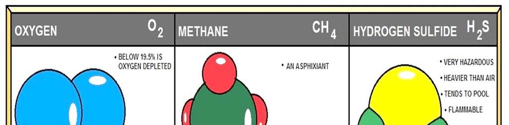

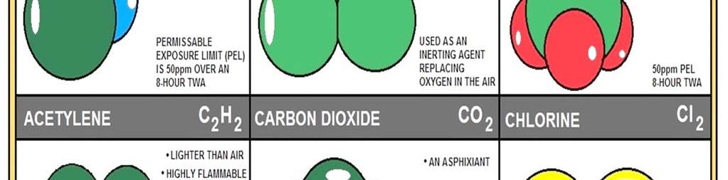

101 101
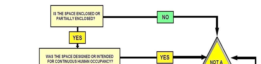
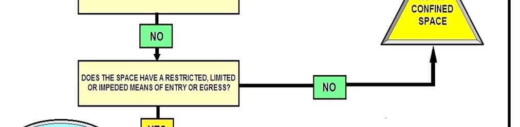
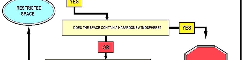
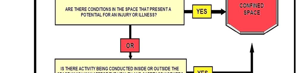
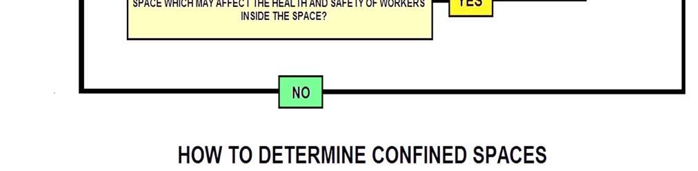
102 102
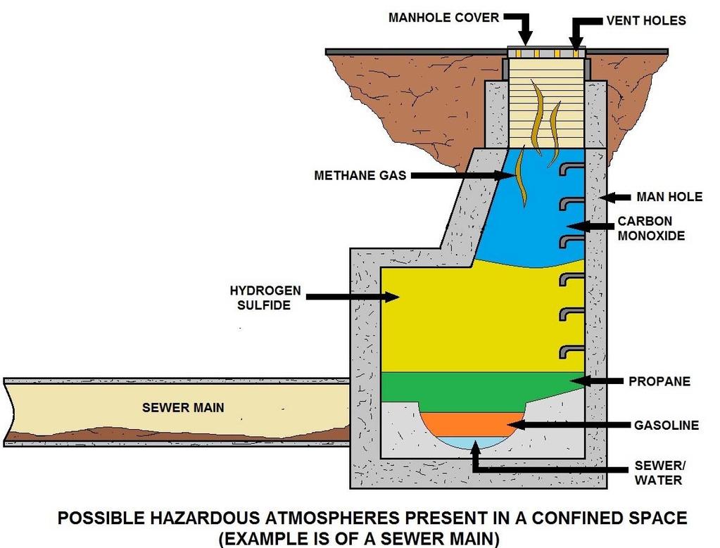
103 103
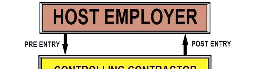

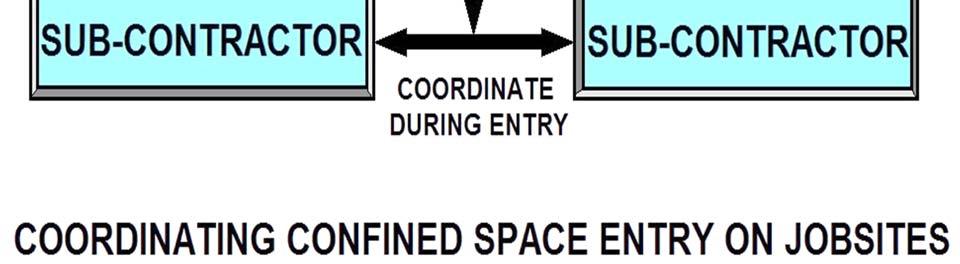
104 104
105 Excavation Glossary Barricades: Visible warning barriers that keep vehicles and pedestrians from entering a construction site. Braces: Devices that hold or fasten two or more parts together or in place. Braces are diagonal or horizontal. They may be made of wood or metal. Bracing System: A system of braces which applies pressure against trench walls to stabilize them. A bracing system is part of a trench shoring system used to prevent trench walls from collapsing. Benching: A method of cutting back the sides of a trench into horizontal steps to prevent cave-ins. Bulge: An outward swelling in the soil of a trench which may be a warning sign of trench failure. Buried Structures: Manholes, junction boxes or catch basins beneath the ground, or any other installations that may be encountered during trenching. Clay: Fine-grained natural soil that is plastic when moist and hard and brittle when dry. Clay is made up of particles smaller than.0002 millimeters. Clumps: Heavy lumps or thick groupings of soil. Cohesion: The relative ability to clump together, the force holding two like substances together. Cohesive: When a soil has grains that hold together and clump well. Competent Person: One who is capable of identifying existing and predictable hazards in the surroundings, or working conditions which are unsanitary, hazardous or dangerous to employees. Has authorization to take prompt corrective measures to eliminate hazards. The Competent Person is trained and knowledgeable about soil analysis and the use of protective systems. Confined Space: Has limited or restricted means of entry or exit, is large enough for an employee to enter and perform assigned work, and is not designed for continuous occupancy by the employee. These spaces may include, but are not limited to, underground vaults, tanks, storage bins, pits, and diked areas, vessels, and silos. Diversion Ditches: A ditch cut around the work site to keep water from entering the trench. Drainage System: Pumps, pipe or channel used to drain off rain or groundwater from inside the trench. Excavation: Any man-made cut, cavity, trench or depression in an earth surface, formed by earth removal. 105
106 Fissure: A long narrow opening or crack in the rock or soil. Fissures are often a sign of trench wall failure. Grain: Particles that once were large rocks, but have been broken down over time and by the effects of weathering. The size of the grain of a soil determines the stability and cohesiveness of a soil. The larger the grain, the more unstable the soil. Gravel: A loose mixture of pebbles and rock fragments, larger particles than sand. Hardpan: A layer of hard subsoil or clay that does not allow water in. Hardpan is classified as a Type A soil. Heaving: The swelling of a soil. Jacks: Jacks are braces or supports within a shoring system. They are placed against beams to resist the pressure of the earth. Loamy Sand: Soil composed of a mixture of sand, clay and silt, with more sand grains than clay or silt. It is classified as a Type C soil. Manufacturer's Tabulated Data: Tables and charts approved by a registered professional engineer and used to design and construct a protective system. Permit Required Confined Space: Meets the definition of a confined space and has one or more of these characteristics: (1) contains or has potential to contain a hazardous atmosphere, (2) contains a material that has the potential for engulfing an entrant, (3) has an internal configuration that might cause an entrant to be trapped or asphyxiated by inwardly converging walls or by a floor that slopes downward and tapers to a smaller cross section, and/or (4) contains any other recognized serious safety or health hazards. Personal Protective Equipment: Includes: safety goggles and glasses, reflective clothing, work gloves, hard hat, safety shoes, rubber boots, earplugs or protectors, face shield and face mask or respirator. Registered Professional Engineer: A person who is registered as a professional engineer in the state where the work is to be performed. Sand: A type C soil with small, loose grains of disintegrated rock. Sandy Loam: Granular soil with enough silt and clay to make it slightly cohesive. Saturation: The process of a soil being filled to capacity with moisture. Shear: A phenomenon which happens when a trench wall is subjected to stress. Fissured cracks widen until a portion of the trench wall breaks off and slides into the trench. Sheeting: Durable sheets of metal or wood, which are held firmly against a trench wall to prevent it from caving-in. Sheeting is a component of a trench shoring system. Shielding: A device which provides adequate protection from falling or collapsing earth loads. The trench box is a common form of shielding. 106
107 Shoring: the main method of stabilizing and supporting a trench wall to prevent cave-ins. It consists of uprights, stingers and braces. Silt: A soil which contains fine particles and is very smooth. Silty Clay: A plastic soil that will appear rough or broken when rubbed over the thumb and finger. Sloping: The process of cutting back the sides of a trench to avoid a cave-in. Sloughing: When loose soil begins to run in from the lower part of the wall into the excavation. It is the first step to a wall collapse. Soil Type: A system of classifying soils and rock deposits. Soil must be classified by a qualified person as: Stable rock, Type-A, Type-B, Type-C. Spall: When a soil begins to crack or flake due to pressure, or from moisture from within the trench. Spoil Pile/Spoilage: The material that is removed from the excavation. Supports: Part of a shoring system which helps to bear the weight of braces and other parts of the shoring system. Trench Box: A prefabricated moveable box usually constructed of metal plates welded to a heavy steel frame. The box is moved along as work progresses. It is able to withstand the forces imposed on it by a cave-in and thereby protects trench workers. Type-A Soil: The most stable and cohesive type of soil while working at a trench site. Examples are clay, silty clay and hardpan. Type-B Soil: Type-B soil is next to the most stable soil. Silt, silt loam, sandy loam, medium clay and unstable rock would be good examples of Type-B soils. Type-C Soil: The least stable type of soil. Examples of Type-C soils are gravel, loamy sand, soft clay, submerged silt and heavy unstable rock. Unconfined Compressive Strength: Through a variety of tests, a soil s strength is found. The unconfined compressive strength is the soil s measure of bearing capacity and shearing resistance. Measured as the amount of weight per square foot needed to collapse a soil sample. Uprights: Vertical members of a trench shoring system placed in context with the earth. These members usually are not placed in direct contact with one another. Vibration: When a soil or excavation site trembles and shakes rapidly due to forces such as loud noises or heavy equipment or traffic. Voids: Voids are empty spaces between particles of rocks. 107


108 Wales: Wales are parts of a shoring system. They are positioned horizontally and help to brace vertical beams and supports. Wales can be fastened to studs with nails, clips or brackets. Wall Stability: The relative strength and capacity of walls of a trench. OSHA Violations--We have a ladder, but it does not extend out of the hole and is not secure. No protective system or hard hats, and the spoil are next to the hole. Notice the electrical cord, we found several sites that utilized electricity. Most contractors utilized worn or frayed extension cords and one contractor even used electrical devices while knee deep in water. We know that construction and excavation is difficult, but think safety first. 108
109 SUBPART P EXCAVATION RULE Scope, application, and definitions applicable to this subpart Specific excavation requirements Requirements for protective systems. APPENDIX A -- SOIL CLASSIFICATION APPENDIX B -- SLOPING AND BENCHING APPENDIX C -- TIMBER SHORING FOR TRENCHES APPENDIX D -- ALUMINUM HYDRAULIC SHORING FOR TRENCHES APPENDIX E TO SUBPART P -- ALTERNATIVES TO TIMBER SHORING APPENDIX F TO SUBPART P -- SELECTION OF PROTECTIVE SYSTEMS Notes Sec. 107, Contract Worker Hours and Safety Standards Act (Construction Safety Act) (40 U.S.C. 333); secs. 4, 6, 8, Occupational Safety and Health Act of 1970 (29 U.S.C. 653, 655, 657); Secretary of Labor's Order No (36 FR 8754), 8-76 (41 FR 25059), or 9-83 (48 FR 35736), as applicable, and 29 CFR part Scope, application, and definitions applicable to this subpart. (a) Scope and application. This subpart applies to all open excavations made in the earth's surface. Excavations are defined to include trenches. (b) Definitions applicable to this subpart. Accepted engineering practices means those requirements which are compatible with standards of practice required by a registered professional engineer. Aluminum Hydraulic Shoring means a pre-engineered shoring system comprised of aluminum hydraulic cylinders (crossbraces) used in conjunction with vertical rails (uprights) or horizontal rails (walers). Such system is designed, specifically to support the sidewalls of an excavation and prevent cave-ins. Bell-bottom pier hole means a type of shaft or footing excavation, the bottom of which is made larger than the cross section above to form a belled shape. Benching (Benching system) means a method of protecting employees from cave-ins by excavating the sides of an excavation to form one or a series of horizontal levels or steps, usually with vertical or nearvertical surfaces between levels. Cave-in means the separation of a mass of soil or rock material from the side of an excavation, or the loss of soil from under a trench shield or support system, and its sudden movement into the excavation, either by falling or sliding, in sufficient quantity so that it could entrap, bury, or otherwise injure and immobilize a person. Competent person means one who is capable of identifying existing and predictable hazards in the surroundings, or working conditions which are unsanitary, hazardous, or dangerous to employees, and who has authorization to take prompt corrective measures to eliminate them. Cross braces mean the horizontal members of a shoring system installed perpendicular to the sides of the excavation, the ends of which bear against either uprights or wales. Excavation means any man-made cut, cavity, trench, or depression in an earth surface, formed by earth removal. Faces or sides means the vertical or inclined earth surfaces formed as a result of excavation work. Failure means the breakage, displacement, or permanent deformation of a structural member or connection so as to reduce its structural integrity and its supportive capabilities. 109
110 Hazardous atmosphere means an atmosphere which by reason of being explosive, flammable, poisonous, corrosive, oxidizing, irritating, oxygen deficient, toxic, or otherwise harmful, may cause death, illness, or injury. Kickout means the accidental release or failure of a cross brace. Protective system means a method of protecting employees from cave-ins, from material that could fall or roll from an excavation face or into an excavation, or from the collapse of adjacent structures. Protective systems include support systems, sloping and benching systems, shield systems, and other systems that provide the necessary protection. Ramp means an inclined walking or working surface that is used to gain access to one point from another, and is constructed from earth or from structural materials such as steel or wood. Registered Professional Engineer means a person who is registered as a professional engineer in the state where the work is to be performed. However, a professional engineer, registered in any state is deemed to be a "registered professional engineer" within the meaning of this standard when approving designs for "manufactured protective systems" or "tabulated data" to be used in interstate commerce. Sheeting means the members of a shoring system that retain the earth in position and in turn are supported by other members of the shoring system. Shield (Shield system) means a structure that is able to withstand the forces imposed on it by a cave-in and thereby protect employees within the structure. Shields can be permanent structures or can be designed to be portable and moved along as work progresses. Additionally, shields can be either premanufactured or job-built in accordance with (c)(3) or (c)(4). Shields used in trenches are usually referred to as "trench boxes" or "trench shields." Shoring (Shoring system) means a structure such as a metal hydraulic, mechanical or timber shoring system that supports the sides of an excavation and which is designed to prevent cave-ins. Sides. See "Faces." Sloping (Sloping system) means a method of protecting employees from cave-ins by excavating to form sides of an excavation that are inclined away from the excavation so as to prevent cave-ins. The angle of incline required to prevent a cave-in varies with differences in such factors as the soil type, environmental conditions of exposure, and application of surcharge loads. Stable rock means natural solid mineral material that can be excavated with vertical sides and will remain intact while exposed. Unstable rock is considered to be stable when the rock material on the side or sides of the excavation is secured against caving-in or movement by rock bolts or by another protective system that has been designed by a registered professional engineer. Structural ramp means a ramp built of steel or wood, usually used for vehicle access. Ramps made of soil or rock are not considered structural ramps. Support system means a structure such as underpinning, bracing, or shoring, which provides support to an adjacent structure, underground installation, or the sides of an excavation. Tabulated data means tables and charts approved by a registered professional engineer and used to design and construct a protective system. Trench (Trench excavation) means a narrow excavation (in relation to its length) made below the surface of the ground. In general, the depth is greater than the width, but the width of a trench (measured at the bottom) is not greater than 15 feet (4.6 m). If forms or other structures are installed or constructed in an excavation so as to reduce the dimension measured from the forms or structure to the side of the 110
111 excavation to 15 feet (4.6 m) or less (measured at the bottom of the excavation), the excavation is also considered to be a trench. Trench box. See "Shield." Trench shield. See "Shield." Uprights means the vertical members of a trench shoring system placed in contact with the earth and usually positioned so that individual members do not contact each other. Uprights placed so that individual members are closely spaced, in contact with or interconnected to each other, are often called "sheeting." Wales means horizontal members of a shoring system placed parallel to the excavation face whose sides bear against the vertical members of the shoring system or earth Specific excavation requirements. (a) Surface encumbrances. All surface encumbrances that are located so as to create a hazard to employees shall be removed or supported, as necessary, to safeguard employees. (b) Underground installations. (1) The estimated location of utility installations, such as sewer, telephone, fuel, electric, water lines, or any other underground installations that reasonably may be expected to be encountered during excavation work, shall be determined prior to opening an excavation. (2) Utility companies or owners shall be contacted within established or customary local response times, advised of the proposed work, and asked to establish the location of the utility underground installations prior to the start of actual excavation. When utility companies or owners cannot respond to a request to locate underground utility installations within 24 hours (unless a longer period is required by state or local law), or cannot establish the exact location of these installations, the employer may proceed, provided the employer does so with caution, and provided detection equipment or other acceptable means to locate utility installations are used. (3) When excavation operations approach the estimated location of underground installations, the exact location of the installations shall be determined by safe and acceptable means. (4) While the excavation is open, underground installations shall be protected, supported or removed as necessary to safeguard employees. (c) Access and egress -- (1) Structural ramps. (i) Structural ramps that are used solely by employees as a means of access or egress from excavations shall be designed by a competent person. Structural ramps used for access or egress of equipment shall be designed by a competent person qualified in structural design, and shall be constructed in accordance with the design. (ii) Ramps and runways constructed of two or more structural members shall have the structural members connected together to prevent displacement. (iii) Structural members used for ramps and runways shall be of uniform thickness. (iv) Cleats or other appropriate means used to connect runway structural members shall be attached to the bottom of the runway or shall be attached in a manner to prevent tripping. (v) Structural ramps used in lieu of steps shall be provided with cleats or other surface treatments on the top surface to prevent slipping. (2) Means of egress from trench excavations. A stairway, ladder, ramp or other safe means of egress shall be located in trench excavations that are 4 feet (1.22 m) or more in depth so as to require no more than 25 feet (7.62 m) of lateral travel for employees. (d) Exposure to vehicular traffic. Employees exposed to public vehicular traffic shall be provided with, and shall wear, warning vests or other suitable garments marked with or made of reflectorized or high-visibility material. (e) Exposure to falling loads. No employee shall be permitted underneath loads handled by lifting or digging equipment. Employees shall be required to stand away from any vehicle being loaded or unloaded to avoid being struck by any spillage or falling materials. Operators may remain in the cabs of vehicles being loaded or unloaded when the vehicles are equipped, in accordance with (b)(6), to provide adequate protection for the operator during loading and unloading operations. (f) Warning system for mobile equipment. When mobile equipment is operated adjacent to an excavation, or when such equipment is required to approach the edge of an excavation, and the operator does not 111
112 have a clear and direct view of the edge of the excavation, a warning system shall be utilized such as barricades, hand or mechanical signals, or stop logs. If possible, the grade should be away from the excavation. (g) Hazardous atmospheres -- (1) Testing and controls. In addition to the requirements set forth in subparts D and E of this part (29 CFR ) to prevent exposure to harmful levels of atmospheric contaminants and to assure acceptable atmospheric conditions, the following requirements shall apply: (i) Where oxygen deficiency (atmospheres containing less than 19.5 percent oxygen) or a hazardous atmosphere exists or could reasonably be expected to exist, such as in excavations in landfill areas or excavations in areas where hazardous substances are stored nearby, the atmospheres in the excavation shall be tested before employees enter excavations greater than 4 feet (1.22 m) in depth. (ii) Adequate precautions shall be taken to prevent employee exposure to atmospheres containing less than 19.5 percent oxygen and other hazardous atmospheres. These precautions include providing proper respiratory protection or ventilation in accordance with subparts D and E of this part respectively. (iii) Adequate precaution shall be taken such as providing ventilation, to prevent employee exposure to an atmosphere containing a concentration of a flammable gas in excess of 20 percent of the lower flammable limit of the gas. (iv) When controls are used that are intended to reduce the level of atmospheric contaminants to acceptable levels, testing shall be conducted as often as necessary to ensure that the atmosphere remains safe. (2) Emergency rescue equipment. (i) Emergency rescue equipment, such as breathing apparatus, a safety harness and line, or a basket stretcher, shall be readily available where hazardous atmospheric conditions exist or may reasonably be expected to develop during work in an excavation. This equipment shall be attended when in use. (ii) Employees entering bell-bottom pier holes, or other similar deep and confined footing excavations, shall wear a harness with a life-line securely attached to it. The lifeline shall be separate from any line used to handle materials, and shall be individually attended at all times while the employee wearing the lifeline is in the excavation. (h) Protection from hazards associated with water accumulation. (1) Employees shall not work in excavations in which there is accumulated water, or in excavations in which water is accumulating, unless adequate precautions have been taken to protect employees against the hazards posed by water accumulation. The precautions necessary to protect employees adequately vary with each situation, but could include special support or shield systems to protect from cave-ins, water removal to control the level of accumulating water, or use of a safety harness and lifeline. (2) If water is controlled or prevented from accumulating by the use of water removal equipment, the water removal equipment and operations shall be monitored by a competent person to ensure proper operation. (3) If excavation work interrupts the natural drainage of surface water (such as streams), diversion ditches, dikes, or other suitable means shall be used to prevent surface water from entering the excavation and to provide adequate drainage of the area adjacent to the excavation. Excavations subject to runoff from heavy rains will require an inspection by a competent person and compliance with paragraphs (h)(1) and (h)(2) of this section. (i) Stability of adjacent structures. (1) Where the stability of adjoining buildings, walls, or other structures is endangered by excavation operations, support systems such as shoring, bracing, or underpinning shall be provided to ensure the stability of such structures for the protection of employees. (2) Excavation below the level of the base or footing of any foundation or retaining wall that could be reasonably expected to pose a hazard to employees shall not be permitted except when: (i) A support system, such as underpinning, is provided to ensure the safety of employees and the stability of the structure; or (ii) The excavation is in stable rock; or (iii) A registered professional engineer has approved the determination that the structure is sufficiently removed from the excavation so as to be unaffected by the excavation activity; or (iv) A registered professional engineer has approved the determination that such excavation work will not pose a hazard to employees. (3) Sidewalks, pavements, and appurtenant structure shall not be undermined unless a support system or another method of protection is provided to protect employees from the possible collapse of such structures. 112
113 (j) Protection of employees from loose rock or soil. (1) Adequate protection shall be provided to protect employees from loose rock or soil that could pose a hazard by falling or rolling from an excavation face. Such protection shall consist of scaling to remove loose material; installation of protective barricades at intervals as necessary on the face to stop and contain falling material; or other means that provide equivalent protection. (2) Employees shall be protected from excavated or other materials or equipment that could pose a hazard by falling or rolling into excavations. Protection shall be provided by placing and keeping such materials or equipment at least 2 feet (.61 m) from the edge of excavations, or by the use of retaining devices that are sufficient to prevent materials or equipment from falling or rolling into excavations, or by a combination of both if necessary. (k) Inspections. (1) Daily inspections of excavations, the adjacent areas, and protective systems shall be made by a competent person for evidence of a situation that could result in possible cave-ins, indications of failure of protective systems, hazardous atmospheres, or other hazardous conditions. An inspection shall be conducted by the competent person prior to the start of work and as needed throughout the shift. Inspections shall also be made after every rainstorm or other hazard increasing occurrence. These inspections are only required when employee exposure can be reasonably anticipated. (2) Where the competent person finds evidence of a situation that could result in a possible cave-in, indications of failure of protective systems, hazardous atmospheres, or other hazardous conditions, exposed employees shall be removed from the hazardous area until the necessary precautions have been taken to ensure their safety. (l) Walkways shall be provided where employees or equipment are required or permitted to cross over excavations. Guardrails which comply with (b) shall be provided where walkways are 6 feet (1.8 m) or more above lower levels Requirements for protective systems. (a) Protection of employees in excavations. (1) Each employee in an excavation shall be protected from cave-ins by an adequate protective system designed in accordance with paragraph (b) or (c) of this section except when: (i) Excavations are made entirely in stable rock; or (ii) Excavations are less than 5 feet (1.52m) in depth and examination of the ground by a competent person provides no indication of a potential cave-in. (2) Protective systems shall have the capacity to resist without failure all loads that are intended or could reasonably be expected to be applied or transmitted to the system. (b) Design of sloping and benching systems. The slopes and configurations of sloping and benching systems shall be selected and constructed by the employer or his designee and shall be in accordance with the requirements of paragraph (b)(1); or, in the alternative, paragraph (b)(2); or, in the alternative, paragraph (b)(3), or, in the alternative, paragraph (b)(4), as follows: (1) Option (1)--Allowable configurations and slopes. (i) Excavations shall be sloped at an angle not steeper than one and one-half horizontal to one vertical (34 degrees measured from the horizontal), unless the employer uses one of the other options listed below. (ii) Slopes specified in paragraph (b)(1)(i) of this section, shall be excavated to form configurations that are in accordance with the slopes shown for Type C soil in Appendix B to this subpart. (2) Option (2)--Determination of slopes and configurations using Appendices A and B. Maximum allowable slopes, and allowable configurations for sloping and benching systems, shall be determined in accordance with the conditions and requirements set forth in appendices A and B to this subpart. (3) Option (3)--Designs using other tabulated data. (i) Designs of sloping or benching systems shall be selected from and be in accordance with tabulated data, such as tables and charts. (ii) The tabulated data shall be in written form and shall include all of the following: (A) Identification of the parameters that affect the selection of a sloping or benching system drawn from such data; (B) Identification of the limits of use of the data, to include the magnitude and configuration of slopes determined to be safe; (C) Explanatory information as may be necessary to aid the user in making a correct selection of a protective system from the data. 113
114 (iii) At least one copy of the tabulated data which identifies the registered professional engineer who approved the data, shall be maintained at the jobsite during construction of the protective system. After that time the data may be stored off the jobsite, but a copy of the data shall be made available to the Secretary upon request. (4) Option (4)--Design by a registered professional engineer. (i) Sloping and benching systems not utilizing Option (1) or Option (2) or Option (3) under paragraph (b) of this section shall be approved by a registered professional engineer. (ii) Designs shall be in written form and shall include at least the following: (A) The magnitude of the slopes that were determined to be safe for the particular project; (B) The configurations that were determined to be safe for the particular project; and (C) The identity of the registered professional engineer approving the design. (iii) At least one copy of the design shall be maintained at the jobsite while the slope is being constructed. After that time the design need not be at the jobsite, but a copy shall be made available to the Secretary upon request. (c) Design of support systems, shield systems, and other protective systems. Designs of support systems shield systems, and other protective systems shall be selected and constructed by the employer or his designee and shall be in accordance with the requirements of paragraph (c)(1); or, in the alternative, paragraph (c)(2); or, in the alternative, paragraph (c)(3); or, in the alternative, paragraph (c)(4) as follows: (1) Option (1)--Designs using appendices A, C and D. Designs for timber shoring in trenches shall be determined in accordance with the conditions and requirements set forth in appendices A and C to this subpart. Designs for aluminum hydraulic shoring shall be in accordance with paragraph (c)(2) of this section, but if manufacturer's tabulated data cannot be utilized, designs shall be in accordance with appendix D. (2) Option (2)--Designs Using Manufacturer's Tabulated Data. (i) Design of support systems, shield systems, or other protective systems that are drawn from manufacturer's tabulated data shall be in accordance with all specifications, recommendations, and limitations issued or made by the manufacturer. (ii) Deviation from the specifications, recommendations, and limitations issued or made by the manufacturer shall only be allowed after the manufacturer issues specific written approval. (iii) Manufacturer's specifications, recommendations, and limitations, and manufacturer's approval to deviate from the specifications, recommendations, and limitations shall be in written form at the jobsite during construction of the protective system. After that time this data may be stored off the jobsite, but a copy shall be made available to the Secretary upon request. (3) Option (3)--Designs using other tabulated data. (i) Designs of support systems, shield systems, or other protective systems shall be selected from and be in accordance with tabulated data, such as tables and charts. (ii) The tabulated data shall be in written form and include all of the following: (A) Identification of the parameters that affect the selection of a protective system drawn from such data; (B) Identification of the limits of use of the data; (C) Explanatory information as may be necessary to aid the user in making a correct selection of a protective system from the data. (iii) At least one copy of the tabulated data, which identifies the registered professional engineer who approved the data, shall be maintained at the jobsite during construction of the protective system. After that time the data may be stored off the jobsite, but a copy of the data shall be made available to the Secretary upon request. (4) Option (4)--Design by a registered professional engineer. (i) Support systems, shield systems, and other protective systems not utilizing Option 1, Option 2 or Option 3, above, shall be approved by a registered professional engineer. (ii) Designs shall be in written form and shall include the following: (A) A plan indicating the sizes, types, and configurations of the materials to be used in the protective system; and (B) The identity of the registered professional engineer approving the design. (iii) At least one copy of the design shall be maintained at the jobsite during construction of the protective system. After that time, the design may be stored off the jobsite, but a copy of the design shall be made available to the Secretary upon request. (d) Materials and equipment. (1) Materials and equipment used for protective systems shall be free from damage or defects that might impair their proper function. 114
115 (2) Manufactured materials and equipment used for protective systems shall be used and maintained in a manner that is consistent with the recommendations of the manufacturer, and in a manner that will prevent employee exposure to hazards. (3) When material or equipment that is used for protective systems is damaged, a competent person shall examine the material or equipment and evaluate its suitability for continued use. If the competent person cannot assure the material or equipment is able to support the intended loads or is otherwise suitable for safe use, then such material or equipment shall be removed from service, and shall be evaluated and approved by a registered professional engineer before being returned to service. (e) Installation and removal of support--(1) General. (i) Members of support systems shall be securely connected together to prevent sliding, falling, kickouts, or other predictable failure. (ii) Support systems shall be installed and removed in a manner that protects employees from cave-ins, structural collapses, or from being struck by members of the support system. (iii) Individual members of support systems shall not be subjected to loads exceeding those which those members were designed to withstand. (iv) Before temporary removal of individual members begins, additional precautions shall be taken to ensure the safety of employees, such as installing other structural members to carry the loads imposed on the support system. (v) Removal shall begin at, and progress from, the bottom of the excavation. Members shall be released slowly so as to note any indication of possible failure of the remaining members of the structure or possible cave-in of the sides of the excavation. (vi) Backfilling shall progress together with the removal of support systems from excavations. (2) Additional requirements for support systems for trench excavations. (i) Excavation of material to a level no greater than 2 feet (.61 m) below the bottom of the members of a support system shall be permitted, but only if the system is designed to resist the forces calculated for the full depth of the trench, and there are no indications while the trench is open of a possible loss of soil from behind or below the bottom of the support system. (ii) Installation of a support system shall be closely coordinated with the excavation of trenches. (f) Sloping and benching systems. Employees shall not be permitted to work on the faces of sloped or benched excavations at levels above other employees except when employees at the lower levels are adequately protected from the hazard of falling, rolling, or sliding material or equipment. (g) Shield systems--(1) General. (i) Shield systems shall not be subjected to loads exceeding those which the system was designed to withstand. (ii) Shields shall be installed in a manner to restrict lateral or other hazardous movement of the shield in the event of the application of sudden lateral loads. (iii) Employees shall be protected from the hazard of cave-ins when entering or exiting the areas protected by shields. (iv) Employees shall not be allowed in shields when shields are being installed, removed, or moved vertically. (2) Additional requirement for shield systems used in trench excavations. Excavations of earth material to a level not greater than 2 feet (.61 m) below the bottom of a shield shall be permitted, but only if the shield is designed to resist the forces calculated for the full depth of the trench, and there are no indications while the trench is open of a possible loss of soil from behind or below the bottom of the shield. 115
116 116
117 APPENDIX A -- SOIL CLASSIFICATION (ii) Dry strength. If the soil is dry and crumbles on its own or with moderate pressure into individual grains or fine powder, it is granular (any combination of gravel, sand, or silt). If the soil is dry and falls into clumps which break up into smaller clumps, but the smaller clumps can only be broken up with difficulty, it may be clay in any combination with gravel, sand or silt. If the dry soil breaks into clumps which do not break up into small clumps and which can only be broken with difficulty, and there is no visual indication the soil is fissured, the soil may be considered unfissured. (iii) Thumb penetration. The thumb penetration test can be used to estimate the unconfined compressive strength of cohesive soils. (This test is based on the thumb penetration test described in American Society for Testing and Materials (ASTM) Standard designation D "Standard Recommended Practice for Description of Soils (Visual -- Manual Procedure).") Type A soils with an unconfined compressive strength of 1.5 tsf can be readily indented by the thumb; however, they can be penetrated by the thumb only with very great effort. Type C soils with an unconfined compressive strength of 0.5 tsf can be easily penetrated several inches by the thumb, and can be molded by light finger pressure. This test should be conducted on an undisturbed soil sample, such as a large clump of spoil, as soon as practicable after excavation to keep to a minimum the effects of exposure to drying influences. If the excavation is later exposed to wetting influences (rain, flooding), the classification of the soil must be changed accordingly. (iv) Other strength tests. Estimates of unconfined compressive strength of soils can also be obtained by use of a pocket penetrometer or by using a hand-operated Shearvane. (v) Drying test. The basic purpose of the drying test is to differentiate between cohesive material with fissures, unfissured cohesive material, and granular material. The procedure for the drying test involves drying a sample of soil that is approximately one inch thick (2.54 cm) and six inches (15.24 cm) in diameter until it is thoroughly dry: (A) If the sample develops cracks as it dries, significant fissures are indicated. (B) Samples that dry without cracking are to be broken by hand. If considerable force is necessary to break a sample, the soil has significant cohesive material content. The soil can be classified as a unfissured cohesive material and the unconfined compressive strength should be determined. (C) If a sample breaks easily by hand, it is either a fissured cohesive material or a granular material. To distinguish between the two, pulverize the dried clumps of the sample by hand or by stepping on them. If the clumps do not pulverize easily, the material is cohesive with fissures. If they pulverize easily into very small fragments, the material is granular. APPENDIX B -- SLOPING AND BENCHING (a) Scope and application. This appendix contains specifications for sloping and benching when used as methods of protecting employees working in excavations from cave-ins. The requirements of this appendix apply when the design of sloping and benching protective systems is to be performed in accordance with the requirements set forth in (b)(2). (b) Definitions. Actual slope means the slope to which an excavation face is excavated. Distress means that the soil is in a condition where a cave-in is imminent or is likely to occur. Distress is evidenced by such phenomena as the development of fissures in the face of or adjacent to an open excavation; the subsidence of the edge of an excavation; the slumping of material from the face or the bulging or heaving of material from the bottom of an excavation; the spalling of material from the face of an excavation; and raveling, i.e., small amounts of material such as pebbles or little clumps of material suddenly separating from the face of an excavation and trickling or rolling down into the excavation. Maximum allowable slope means the steepest incline of an excavation face that is acceptable for the most favorable site conditions as protection against cave-ins, and is expressed as the ratio of horizontal distance to vertical rise (H:V). Short term exposure means a period of time less than or equal to 24 hours that an excavation is open. (c) Requirements -- (1) Soil classification. Soil and rock deposits shall be classified in accordance with appendix A to subpart P of part (2) Maximum allowable slope. The maximum allowable slope for a soil or rock deposit shall be determined from Table B-1 of this appendix. (3) Actual slope. (i) The actual slope shall not be steeper than the maximum allowable slope. 117
118 (ii) The actual slope shall be less steep than the maximum allowable slope, when there are signs of distress. If that situation occurs, the slope shall be cut back to an actual slope which is at least 1/2 horizontal to one vertical ( 1/2 H:1V) less steep than the maximum allowable slope. (iii) When surcharge loads from stored material or equipment, operating equipment, or traffic are present, a competent person shall determine the degree to which the actual slope must be reduced below the maximum allowable slope, and shall assure that such reduction is achieved. Surcharge loads from adjacent structures shall be evaluated in accordance with (i). (4) Configurations. Configurations of sloping and benching systems shall be in accordance with Figure B- 1. APPENDIX C -- TIMBER SHORING FOR TRENCHES (B) When vertical loads imposed on cross braces exceed a 240-pound gravity load distributed on a onefoot section of the center of the crossbrace. (C) When surcharge loads are present from equipment weighing in excess of 20,000 pounds. (D) When only the lower portion of a trench is shored and the remaining portion of the trench is sloped or benched unless: The sloped portion is sloped at an angle less steep than three horizontal to one vertical; or the members are selected from the tables for use at a depth which is determined from the top of the overall trench, and not from the toe of the sloped portion. (e) Use of Tables. The members of the shoring system that are to be selected using this information are the cross braces, the uprights, and the wales, where wales are required. Minimum sizes of members are specified for use in different types of soil. There are six tables of information, two for each soil type. The soil type must first be determined in accordance with the soil classification system described in appendix A to subpart P of part Using the appropriate table, the selection of the size and spacing of the members is then made. The selection is based on the depth and width of the trench where the members are to be installed and, in most instances, the selection is also based on the horizontal spacing of the crossbraces. Instances where a choice of horizontal spacing of crossbracing is available, the horizontal spacing of the crossbraces must be chosen by the user before the size of any member can be determined. When the soil type, the width and depth of the trench, and the horizontal spacing of the crossbraces are known, the size and vertical spacing of the crossbraces, the size and vertical spacing of the wales, and the size and horizontal spacing of the uprights can be read from the appropriate table. (f) Examples to Illustrate the Use of Tables C-1.1 through C-1.3. (1) Example 1. A trench dug in Type A soil is 13 feet deep and five feet wide. From Table C-1.1, for acceptable arrangements of timber can be used. Arrangement #1 Space 4 X 4 crossbraces at six feet horizontally and four feet vertically. Wales are not required. Space 38 uprights at six feet horizontally. This arrangement is commonly called "skip shoring." Arrangement #2 Space 4 X 6 crossbraces at eight feet horizontally and four feet vertically. Space 8 X 8 wales at four feet vertically. Space 2 X 6 uprights at four feet horizontally. Arrangement #3 Space 6 X 6 crossbraces at 10 feet horizontally and four feet vertically. Space 8 X 10 wales at four feet vertically. Space 2 X 6 uprights at five feet horizontally. Arrangement #4 Space 6 X 6 crossbraces at 12 feet horizontally and four feet vertically. Space 10 X 10 wales at four feet vertically. Spaces 3 X 8 uprights at six feet horizontally. (2) Example 2. A trench dug in Type B soil in 13 feet deep and five feet wide. From Table C-1.2 three acceptable arrangements of members are listed. Arrangement #1 Space 6 X 6 crossbraces at six feet horizontally and five feet vertically. 118
119 Space 8 X 8 wales at five feet vertically. Space 2 X 6 uprights at two feet horizontally. Arrangement #2 Space 6 X 8 crossbraces at eight feet horizontally and five feet vertically. Space 1010 wales at five feet vertically. Space 2 X 6 uprights at two feet horizontally. Arrangement #3 Space 8 X 8 crossbraces at 10 feet horizontally and five feet vertically. Space 10 X 12 wales at five feet vertically. Space 2 X 6 uprights at two feet vertically. (3) Example 3. A trench dug in Type C soil is 13 feet deep and five feet wide. From Table C-1.3 two acceptable arrangements of members can be used. Arrangement #1 Space 8 X 8 crossbraces at six feet horizontally and five feet vertically. Space 10 X 12 wales at five feet vertically. Position 2 X 6 uprights as closely together as possible. If water must be retained use special tongue and groove uprights to form tight sheeting. Arrangement #2 Space 8 X 10 crossbraces at eight feet horizontally and five feet vertically. Space 12 X 12 wales at five feet vertically. Position 2 X 6 uprights in a close sheeting configuration unless water pressure must be resisted. Tight sheeting must be used where water must be retained. (4) Example 4. A trench dug in Type C soil is 20 feet deep and 11 feet wide. The size and spacing of members for the section of trench that is over 15 feet in depth is determined using Table C-1.3. Only one arrangement of members is provided. Space 8 X 10 crossbraces at six feet horizontally and five feet vertically. Space 12 X 12 wales at five feet vertically. Use 3 X 6 tight sheeting. Use of Tables C-2.1 through C-2.3 would follow the same procedures. (g) Notes for all Tables. 1. Member sizes at spacings other than indicated are to be determined as specified in (c), "Design of Protective Systems." 2. When conditions are saturated or submerged use Tight Sheeting. Tight Sheeting refers to the use of specially-edged timber planks (e.g., tongue and groove) at least three inches thick, steel sheet piling, or similar construction that when driven or placed in position provide a tight wall to resist the lateral pressure of water and to prevent the loss of backfill material. Close Sheeting refers to the placement of planks sideby-side allowing as little space as possible between them. 3. All spacing indicated is measured center to center. 4. Wales to be installed with greater dimension horizontal. 5. If the vertical distance from the center of the lowest crossbrace to the bottom of the trench exceeds two and one-half feet, uprights shall be firmly embedded or a mudsill shall be used. Where uprights are embedded, the vertical distance from the center of the lowest crossbrace to the bottom of the trench shall not exceed 36 inches. When mudsills are used, the vertical distance shall not exceed 42 inches. Mudsills are wales that are installed at the toe of the trench side. 6. Trench jacks may be used in lieu of or in combination with timber crossbraces. 7. Placement cf crossbraces. When the vertical spacing of crossbraces is four feet, place the top crossbrace no more than two feet below the top of the trench. When the vertical spacing of crossbraces is five feet, place the top crossbrace no more than 2.5 feet below the top of the trench. 119
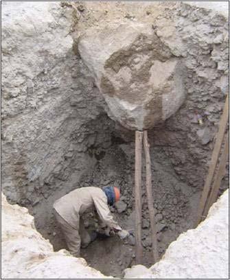
120 120
121 OVERVIEW: SOIL MECHANICS A number of stresses and deformations can occur in an open cut or trench. For example, increases or decreases in moisture content can adversely affect the stability of a trench or excavation. The following diagrams show some of the more frequently identified causes of trench failure. TENSION CRACKS. Tension cracks usually form at a horizontal distance of 0.5 to 0.75 times the depth of the trench, measured from the top of the vertical face of the trench. See the accompanying drawing for additional details. FIGURE 5:2-1. TENSION CRACK. SLIDING or sluffing may occur as a result of tension cracks, as illustrated below. FIGURE 5:2-2. SLIDING. TOPPLING. In addition to sliding, tension cracks can cause toppling. Toppling occurs when the trench's vertical face shears along the tension crack line and topples into the excavation. FIGURE 5:2-3. TOPPLING. SUBSIDENCE AND BULGING. An unsupported excavation can create an unbalanced stress in the soil, which, in turn, causes subsidence at the surface and bulging of the vertical face of the trench. If uncorrected, this condition can cause face failure and entrapment of workers in the trench. FIGURE 5:2-4. SUBSIDENCE AND BULGING. 121
122 HEAVING OR SQUEEZING. Bottom heaving or squeezing is caused by the downward pressure created by the weight of adjoining soil. This pressure causes a bulge in the bottom of the cut, as illustrated in the drawing above. Heaving and squeezing can occur even when shoring or shielding has been properly installed. BOILING is evidenced by an upward water flow into the bottom of the cut. A high water table is one of the causes of boiling. Boiling produces a "quick" condition in the bottom of the cut, and can occur even when shoring or trench boxes are used. FIGURE 5:2-5. HEAVING OR SQUEEZING. FIGURE 5:2-6. BOILING. UNIT WEIGHT OF SOILS refers to the weight of one unit of a particular soil. The weight of soil varies with type and moisture content. One cubic foot of soil can weigh from 110 pounds to 140 pounds or more, and one cubic meter (35.3 cubic feet) of soil can weigh more than 3,000 pounds. DETERMINATION OF SOIL TYPE. OSHA categorizes soil and rock deposits into four types, A through D, as follows: STABLE ROCK is natural solid mineral matter that can be excavated with vertical sides and remain intact while exposed. It is usually identified by a rock name such as granite or sandstone. Determining whether a deposit is of this type may be difficult unless it is known whether cracks exist and whether or not the cracks run into or away from the excavation. TYPE A SOILS are cohesive soils with an unconfined compressive strength of 1.5 tons per square foot (tsf) (144 kpa) or greater. Examples of Type A cohesive soils are often: clay, silty clay, sandy clay, clay loam and, in some cases, silty clay loam and sandy clay loam. (No soil is Type A if it is fissured, is subject to vibration of any type, has previously been disturbed, is part of a sloped, layered system where the layers dip into the excavation on a slope of 4 horizontal to 1 vertical (4H:1V) or greater, or has seeping water. TYPE B SOILS are cohesive soils with an unconfined compressive strength greater than 0.5 tsf (48 kpa) but less than 1.5 tsf (144 kpa). Examples of other Type B soils are: angular gravel; silt; silt loam; previously disturbed soils unless otherwise classified as Type C; soils that meet the unconfined compressive strength or cementation requirements of Type A soils but are fissured or subject to vibration; dry unstable rock; and layered systems sloping into the trench at a slope less than 4H:1V (only if the material would be classified as a Type B soil). TYPE C SOILS are cohesive soils with an unconfined compressive strength of 0.5 tsf (48 kpa) or less. Other Type C soils include granular soils such as gravel, sand and loamy sand, submerged soil, soil from which water is freely seeping, and submerged rock that is not stable. Also included in this 122
123 classification is material in a sloped, layered system where the layers dip into the excavation or have a slope of four horizontal to one vertical (4H:1V) or greater. LAYERED GEOLOGICAL STRATA. Where soils are configured in layers, i.e., where a layered geologic structure exists, the soil must be classified on the basis of the soil classification of the weakest soil layer. Each layer may be classified individually if a more stable layer lies below a less stable layer, i.e., where a Type C soil rests on top of stable rock. TEST EQUIPMENT AND METHODS FOR EVALUATING SOIL TYPE. Many kinds of equipment and methods are used to determine the type of soil prevailing in an area, as described below. POCKET PENETROMETER. Penetrometers are direct-reading, spring-operated instruments used to determine the unconfined compressive strength of saturated cohesive soils. Once pushed into the soil, an indicator sleeve displays the reading. The instrument is calibrated in either tons per square foot (tsf) or kilograms per square centimeter (kpa). However, Penetrometers have error rates in the range of ± 20-40%. Shearvane (Torvane). To determine the unconfined compressive strength of the soil with a shearvane, the blades of the vane are pressed into a level section of undisturbed soil, and the torsional knob is slowly turned until soil failure occurs. The direct instrument reading must be multiplied by 2 to provide results in tons per square foot (tsf) or kilograms per square centimeter (kpa). Thumb Penetration Test. The thumb penetration procedure involves an attempt to press the thumb firmly into the soil in question. If the thumb makes an indentation in the soil only with great difficulty, the soil is probably Type A. If the thumb penetrates no further than the length of the thumb nail, it is probably Type B soil, and if the thumb penetrates the full length of the thumb, it is Type C soil. The thumb test is subjective and is therefore the least accurate of the three methods. Dry Strength Test. Dry soil that crumbles freely or with moderate pressure into individual grains is granular. Dry soil that falls into clumps that subsequently break into smaller clumps (and the smaller clumps can be broken only with difficulty) is probably clay in combination with gravel, sand, or silt. If the soil breaks into clumps that do not break into smaller clumps (and the soil can be broken only with difficulty), the soil is considered unfissured unless there is visual indication of fissuring. PLASTICITY OR WET THREAD TEST. This test is conducted by molding a moist sample of the soil into a ball and attempting to roll it into a thin thread approximately 1/8 inch (3 mm) in diameter (thick) by 2 inches (50 mm) in length. The soil sample is held by one end. If the sample does not break or tear, the soil is considered cohesive. VISUAL TEST. A visual test is a qualitative evaluation of conditions around the site. In a visual test, the entire excavation site is observed, including the soil adjacent to the site and the soil being excavated. If the soil remains in clumps, it is cohesive; if it appears to be coarse-grained sand or gravel, it is considered granular. The evaluator also checks for any signs of vibration. During a visual test, the evaluator should check for crack-line openings along the failure zone that would indicate tension cracks, look for existing utilities that indicate that the soil has previously been disturbed, and observe the open side of the excavation for indications of layered geologic structuring. The evaluator should also look for signs of bulging, boiling, or sluffing, as well as for signs of surface water seeping from the sides of the excavation or from the water table. If there is standing water in the cut, the evaluator should check for "quick" conditions (see Paragraph III. F. in this chapter). 123
124 SHORING TYPES Shoring is the provision of a support system for trench faces used to prevent movement of soil, underground utilities, roadways, and foundations. Shoring or shielding is used when the location or depth of the cut makes sloping back to the maximum allowable slope impractical. Shoring systems consist of posts, wales, struts, and sheeting. There are two basic types of shoring, timber and aluminum hydraulic. FIGURE V:2-7. TIMBER SHORING. HYDRAULIC SHORING. The trend today is toward the use of hydraulic shoring, a prefabricated strut and/or wale system manufactured of aluminum or steel. Hydraulic shoring provides a critical safety advantage over timber shoring because workers do not have to enter the trench to install or remove hydraulic shoring. Other advantages of most hydraulic systems are that they: Are light enough to be installed by one worker; Are gauge-regulated to ensure even distribution of pressure along the trench line; Can have their trench faces "preloaded" to use the soil's natural cohesion to prevent movement; and Can be adapted easily to various trench depths and widths. All shoring should be installed from the top down and removed from the bottom up. Hydraulic shoring should be checked at least once per shift for leaking hoses and/or cylinders, broken connections, cracked nipples, bent bases, and any other damaged or defective parts. 124

125 SHORING VARIATIONS: TYPICAL ALUMINUM HYDRAULIC SHORING INSTALLATIONS PNEUMATIC SHORING works in a manner similar to hydraulic shoring. The primary difference is that pneumatic shoring uses air pressure in place of hydraulic pressure. A disadvantage to the use of pneumatic shoring is that an air compressor must be on site. 125
126 126
127 FIGURE V:2-13. SLOPE CONFIGURATIONS: EXCAVATIONS IN LAYERED SOILS. FIGURE V:2-14. EXCAVATIONS MADE IN TYPE A SOIL. BENCHING. There are two basic types of benching, simple and multiple. The type of soil determines the horizontal to vertical ratio of the benched side. As a general rule, the bottom vertical height of the trench must not exceed 4 ft (1.2 m) for the first bench. Subsequent benches may be up to a maximum of 5 ft (1.5 m) vertical in Type A soil and 4 ft (1.2 m) in Type B soil to a total trench depth of 20 ft (6.0 m). All subsequent benches must be below the maximum allowable slope for that soil type. For Type B soil the trench excavation is permitted in cohesive soil only. 127
128 FIGURE V:2-15. EXCAVATIONS MADE IN TYPE B SOIL. SPOIL TEMPORARY SPOIL. Temporary spoil must be placed no closer than 2 ft (0.61 m) from the surface edge of the excavation, measured from the nearest base of the spoil to the cut. This distance should not be measured from the crown of the spoil deposit. This distance requirement ensures that loose rock or soil from the temporary spoil will not fall on employees in the trench. Spoil should be placed so that it channels rainwater and other run-off water away from the excavation. Spoil should be placed so that it cannot accidentally run, slide, or fall back into the excavation. FIGURE V:2-16. TEMPORARY SPOIL. PERMANENT SPOIL. Permanent spoil should be placed at some distance from the excavation. Permanent spoil is often created where underpasses are built or utilities are buried. The improper placement of permanent spoil, i.e. insufficient distance from the working excavation, can cause an excavation to be out of compliance with the horizontal-to-vertical ratio requirement for a particular excavation. This can usually be determined through visual observation. Permanent spoil can change undisturbed soil to disturbed soil and dramatically alter slope requirements. 128
: ILO, Geneva, Switzerland. National Safety Council.")

129 References 29 CFR 1926, Subpart P. Excavations. Construction Safety Association of Ontario. Trenching Safety. 74 Victoria St., Toronto, Ontario, Canada M5C2A5. International Labour Office (ILO). Building Work: A Compendium of Occupational Safety and Health Practice. International Occupational Safety and Health Information Centre (CIS): ILO, Geneva, Switzerland. National Safety Council. Accident Prevention Manual for Industrial Operations, Engineering and Technology, 9th ed., Chicago, IL: National Safety Council. National Safety Council. Protecting Worker's Lives: A Safety and Health Guide for Unions. Chicago, IL: National Safety Council. National Safety Council. Industrial Data Sheets: I-482, General Excavation, and I-254, Trench Excavation, Chicago, IL: National Safety Council. National Utility Contractors Association, Competent Person Manual NBS/NIOSH, Development of Draft Construction Safety Standards for Excavations. Volume I, April NIOSH , Pub. No Volume II, April NIOSH , Pub. No Scardino, A.J., Jr Hazard Identification and Control--Trench Excavation. Lagrange, TX: Carlton Press. Melissa Durbin, Author and Dean of Instruction. 129
130 130
131 DAILY EXCAVATION CHECKLIST Client Project Name Project Location Job Number Excavation Depth & Width Protective System Used Activities In Excavation Competent Person Date Approx. Temp. Approx. Wind Dir. Safety Rep Soil Classification Excavation > 4 feet deep? Yes No NOTE: Trenches over 4 feet in depth are considered excavations. Any items marked NO on this form MUST be remediated prior to any employees entering the excavation. YES NO N/A DESCRIPTION GENERAL Employees protected from cave-ins & loose rock/soil that could roll into the excavation. Spoils, materials & equipment set back at least 2 feet from the edge of the excavation. Engineering designs for sheeting &/or manufacturer's data on trench box capabilities on site. Adequate signs posted and barricades provided. Training (toolbox meeting) conducted w/ employees prior to entering excavation. UTILITIES Utility company contacted & given 24 hours notice &/or utilities already located & marked. Overhead lines located, noted and reviewed with the operator. Utility locations reviewed with the operator, & precautions taken to ensure contact does not occur. Utilities crossing the excavation supported, and protected from falling materials. Underground installations protected, supported or removed when excavation is open. WET CONDITIONS Precautions taken to protect employees from water accumulation (continuous dewatering). Surface water or runoff diverted /controlled to prevent accumulation in the excavation. Inspection made after every rainstorm or other hazard increasing occurrence. 131
132 HAZARDOUS ATMOSPHERES Air in the excavation tested for oxygen deficiency, combustibles, and other contaminants. Ventilation used in atmospheres that are oxygen rich/deficient &/or contains hazardous substances. Ventilation provided to keep LEL below 10 %. Emergency equipment available where hazardous atmospheres could or do exist. Safety harness and lifeline used. Supplied air necessary (if yes, contact safety department). ENTRY & EXIT Exit (i.e. ladder, sloped wall) no further than 25 feet from ANY employee. Ladders secured and extend 3 feet above the edge of the trench. Wood ramps constructed of uniform material thickness, cleated the bottom. Employees protected from cave-ins when entering or exiting the excavation. Explain how you have secured the site and made it safe to work inside (if possible) 132
133 Competent Person Pre-Exam This is not your final assignment. You can find a copy of that on our website under Assignments. This is only a practice exam. 1. If soil clumps when it is dug, it is probablya. Very unstable b. Type-C soil. c. Cohesive and stable. 2. Soil that is completely saturated with water isa. Unstable b. Stable c. Type-A soil 3. Trench sites are often made up ofa. Exactly the same type of soil. b. Stable rock. c. Different soil types. 4. A Competent Person should manually test the soila. Every day. b. Once every three days. c. From within the trench. d. If something causes the soil conditions to deteriorate. 5. Soil is categorized to determinea. How well it will hold up in a trench. b. The cohesive tension and backdraft. c. How old it is. 6. Which soil is the most stable? a. Type A b. Type B c. Type C 7. Excavation work is not really as dangerous as some believe. a. True b. False 8. One Call centers will usually take to be down on the ground. a. 1 day. b. 2 days. c. 3 days. 133
134 9. As a rule, soils with larger grain sizes area. Less stable than soils with smaller grain sizes. b. Very stable. 10. A confined space can be founda. Vault b. Tank. c. Silos. d. Bell-shaped hole e. All of the above. 11. Hard hats are only required ifa. My supervisor is present. b. Around any construction. c. If my head feels soft. 12. Which of the following is usually true about Benching and Sloping? a. Stable soils must be at flatter angles. b. The flatter the angle, the greater the protection. c. The soil type is not important. d. They are both dangerous practices. 13. Select the right Benching and Sloping ratio for Type-C soil. a..75:1 b. 1:1 c. 1.5:1 d Select the type of soil that is Benched at a ratio of 1:1. a. Solid rock b. Sand c. Gravel d. Silt 15. The instructions contained in the tabulated data chartsa. Are boring. b. Must be followed exactly. c. Are suggestions. d. Can be changed by a real good Competent Person, like me. 16. If a hazardous atmosphere is suspected, what must the Competent Person do before anyone goes into the trench? a. Light a match. b. Test the air. c. Test the employees for holding their breaths. d. Install shoring or shielding, quickly. 134
135 17. If your trench box is not high enough, you shoulda. Use steel sheeting to make the box higher. b. Not use a protective device. c. Stack two approved trench boxes and attach them together with lugs. d. None of the above. 18. Select the support which you would remove first in a shoring system. a. Top b. Middle c. Bottom d. Doesn t manner 19. A Competent Person is required to inspect the trench sitea. Once each day. b. Each day before work begins and throughout the day if necessary. c. Twice a week. d. Whenever it s convenient. 20. Spoil piles should be kept how far back from the edge of the trench? a. At least 2 feet. b. 1 foot. c. Depends d. 5 feet. 21. What is a condition of having water present the trench? a. A Competent Person must monitor the pump and may need to add a protective system in a trench less than 5 feet deep. b. No problem, unless you are made of sugar. c. Never happens. 22. A safe level of oxygen isa. 18 % b % c. 25 % d. 20 % 23. LEL meansa. Lowest Employee Loss b. Lower Explosive Lemon c. Lower Explosive Limitation d. None of the above. 24. The most dangerous construction work todaya. Postal Worker b. Excavation c. Is being on the Boss s bad side 135
136 25. You should have the following at your job site: a. A written Hazard Communication program b. A copy of Subpart P c. A trench inspection form. d. Current CPR training e. All of the above. 26. If a trench is deeper than four feet, there must be a ladder or safe means of exit within how many feet of each worker? a. 15 b. 25 c. 30 d A Competent Person must be able toa. Identify hazards and eliminate them. b. Design and install trench boxes. c. Operate heavy equipment d. Leave the construction site during trench work. e. Cook lunch for the workers. 28. Who needs to know the proper trenching procedures? a. Only the contractor b. Only the Competent Person. c. Only the Registered Professional Engineer d. All workers at a trench site. 29. Egress meansa. A stairway b. A ramp c. An exit d. A ladder 30. This training is necessary for all who work in trenches, but a. This will slow production. I might look bad. b. A trench will never cave-in with me. I ll jump out of the hole first. c. Anybody with common sense knows this. d. Is a waste of time, my boss doesn t really care. e. Excavation is very dangerous work and training may seem boring but I need to know the hazards in the field. 136
137 The following questions will come from the Glossary and are fill-in-the blank type answers. 31. One who is capable of identifying existing and predictable hazards in the surroundings, or working conditions which are unsanitary, hazardous or dangerous to employees. Has authorization to take prompt corrective measures to eliminate hazards. The Competent Person is trained and knowledgeable about soil analysis and the use of protective systems. 32. Has limited or restricted means of entry or exit, is large enough for an employee to enter and perform assigned work, and is not designed for continuous occupancy by the employee. These spaces may include, but not limited to, underground vaults, tanks, storage bins, pits, and diked areas, vessels, and silos. 33. A ditch cut around the work site to keep water from entering the trench. 34. Pumps, pipe or channel used to drain off rain or groundwater from inside the trench. 35. Any man-made cut, cavity trench or depression in an earth surface, formed by earth removal. 36. A long narrow opening or crack in the rock or soil. Often a sign of trench wall failure. 37. Visible warning barriers that keep vehicles and pedestrians from entering a construction site. 38. Devices that hold or fasten two or more parts together or in place; diagonal or horizontal. They may be made of wood or metal. 39. A system of braces which applies pressure against trench walls to stabilize them. A bracing system is part of a trench shoring system used to prevent trench walls from collapsing. 40. A method of cutting back the sides of a trench into horizontal steps to prevent cave-ins. 41. An outward swelling in the soil of a trench. May be a warning sign of trench failure. 42. Manholes, junction boxes or catch basins beneath the ground or any other installations that may be encountered during trenching. 43. Fine-grained natural soil that is plastic when moist and hard and brittle when dry. Made up of particles smaller than.0002 millimeters. 44. Heavy lumps or thick groupings of soil. 137
138 45. The relative ability to clump together, the force holding two like substances together. 46. When a soil has grains that hold together and clump well. 47. The least stable type of soil. Examples are gravel, loamy sand, soft clay, submerged silt and heavy unstable rock. 48. Through a variety of tests, a soil s strength is found. The soil s measure of bearing capacity and shearing resistance. Measured as the amount of weight per square foot needed to collapse a soil sample. 49. Vertical members of a trench shoring system placed in context with the earth. These members usually are not placed in direct contact with one another. 50. When a soil or excavation site trembles and shakes rapidly due to forces such as loud noises or heavy equipment or traffic. 51. empty spaces between particles of rocks. 52. Parts of a shoring system. They are positioned horizontally and help to brace vertical beams and supports. Can be fastened to studs with nails, clips or brackets. 53. The relative strength and capacity of walls of a trench. 54. Particles that once were large rocks, but have been broken down through time and the effects of weathering. The size determines the stability and cohesiveness of a soil. The larger the grain, the more unstable the soil. 55. A loose mixture of pebbles and rock fragments, which is coarser than sand. 56. A layer of hard subsoil or clay that does not allow water in. Classified as a Type A soil. 57. The swelling of a soil. 58. Braces or supports within a shoring system. They are placed against beams to resist the pressure of the earth. 59. Soil composed of a mixture of sand, clay and silt, with more sand grains than clay or silt. It is classified as a Type C soil. 60. Tables and charts approved by a registered professional engineer and used to design and construct a protective system. 138
139 61. Meets the definition of a confined space and has one or more of these characteristics: (1) contains or has potential to contain a hazardous atmosphere, (2) contains a material that has the potential for engulfing an entrant, (3) has an internal configuration that might cause an entrant to be trapped or asphyxiated by inwardly converging walls or by a floor that slopes downward and tapers to a smaller cross section, and/or (4) contains any other recognized serious safety or health hazards. 62. Includes: safety goggles and glasses, reflective clothing, work gloves, hard hat, safety shoes, rubber boots, earplugs or protectors, face shield and face mask or respirator. 63. A person who is registered as a professional engineer in the state where the work is to be performed. 64. A type C soil with small, loose grains of disintegrated rock. 65. Granular soil with enough silt and clay to make it slightly cohesive 66. The process of a soil being filled to capacity with moisture. 67. A phenomenon which happens when a trench wall is subjected to stress. Fissured cracks widen until a portion of the trench wall breaks off and slides into the trench. 68. Durable sheets of metal or wood, which are held firmly against a trench wall to prevent it from caving-in. A component of a trench shoring system. 69. A device which provides adequate protection from falling or collapsing earth loads. The trench box is a common form. 70. The main method of stabilizing and supporting a trench wall to prevent cave-ins. It consists of uprights, stingers and braces. 71. A soil which contains fine particles and is very smooth. 72. Plastic soil that will appear rough or broken when rubbed over the thumb and finger. 73. The process of cutting back the sides of a trench to avoid a cave-in. 74. When loose soil begins to run in from the lower part of the wall into the excavation. It is the first step to a wall collapse. 75. A system of classifying soils and rock deposits. Soil must be classified by a qualified person as: Stable rock, Type-A, Type-B, Type-C. 139
140 76. When a soil begins to crack or flake due to pressure, or from moisture from within the trench. 77. Rock waste, banks and dumps from the excavation. 78. Part of a shoring system which helps to bear the weight of braces and other parts of the shoring system. 79. A prefabricated moveable box usually constructed of metal plates welded to a heavy steel frame. The box is moved along as work progresses. It is able to withstand the forces imposed on it by a cave-in and thereby protects trench workers. 80. The most stable and cohesive type of soil while working at a trench site. Examples are clay, silty clay and hardpan. Third and final part of your pre-exam. 140

141 Third and final part of your pre-exam. The following are actual scenarios. You are the Competent Person and need to make a few decisions. There are several methods to correct these scenarios, you are to fill out the Excavation Forms on found on page 111 or use your own form on each scenario. You do not need to complete a Confined Space Form for this assignment. Scenario # 1 : N. 10th Ave You will work on this site for two weeks. Should you order different barricades? What other items do you need or should you use? Type C soil. Excavation is dry. Utilities have been marked, but the spoil pile has covered and removed the marks. Oxygen level is 19.7%. All other gases are fine. The Gas Station Manager keeps coming into your work zone and complains that you are causing his business to lose customers because of your traffic set-up. The trench is 8 feet deep. No Rain, 90 degrees outside, no wind. You are installing new water lines, and find a supposed abandoned plastic gas main in your excavation. Your Spotter, accidentally broke a marked street light with his shooter shovel. 141

142 Do not utilize damaged, bent, or broken shores. For some reason, we like to collect these and use them on a daily basis. Let s stop that practice and throw the damaged ones away. 142

143 Scenario # W. Montebello You have been assigned to place a new water service to the water main. (The large line is the water main. Locates are complete, but you have found three plastic lines next to the water line. It is raining, windy, and 75 degrees outside. The excavation is in the middle of an alley and is 5 feet 4 inches deep and two feet wide. It has been a long day and you are unable to bench the hole because homeowners fences are in the way. O2 and all other gases are good and nobody is around to watch you work. Type C soil. How should you proceed? 143


144 Aluminum Hydraulic Shields Lightweight aluminum construction allows for use of backhoes/loaders to lift, swing, and place. Larger inside working area due to elimination of horizontal bracing. Economical hand pump pressurizes cylinders easily and efficiently. Spring returns for easy contraction and removal of shield from trench. Hydraulic cylinders pre-load trench walls and accommodate varying trench widths. "Competent Person" The term "Competent Person" is used in many OSHA standards and documents. As a general rule, the term is not specifically defined. In a broad sense, an OSHA competent person is an individual who, by way of training and/or experience, is knowledgeable of applicable standards, is capable of identifying workplace hazards relating to the specific operation, is designated by the employer, and has authority to take appropriate actions (see ). Some standards add additional specific requirements which must be met by the competent person. 144


145 Scenario #3: 604 W. Forest As usual, you were home watching TV on your day off. The Dispatcher has called you and your crew to a water line break. You are the last one to get to the job site. Your Number 1 Man is a go-getter and has hand dug to the leak and will attempt to fix it by himself. He is an over-achiever. Do you know him? No locates or utilities have been marked. Very sandy soil, but your Go-Getter says that the hole is only 4-5 feet deep and he can get it. It is 90 degrees outside, no wind and no gas readings. Your Go-Getter is the best crewmember you have, but he forgets safety PPE. If the leak is not fixed soon, you may have to shut the water main off to 50 homes in the richest side of town. How should you proceed? 145


146 Speed shoring type set-up system Adequate Protection: Protection of employees from loose rock or soil. Adequate protection shall be provided to protect employees from loose rock or soil that could pose a hazard by falling or rolling from an excavation face. Such protection shall consist of scaling to remove loose material; installation of protective barricades at intervals as necessary on the face to stop and contain falling material; or other means that provide equivalent protection. Always use a ladder. Most of the trenches that we visited did not have a ladder. 146

147 Scenario # E. Culver St You have been sent to this site to be the Competent Person and oversee the construction. Once you get there, you see that the homeowner is allowing his son to play in the excavation. Oxygen level is 19.7%. All other gases are fine. No rain, Type C soil, the bottom of this excavation is 17 feet deep, the ladder is 5 feet long, locates are down but are 21 days old. How should you proceed? 147

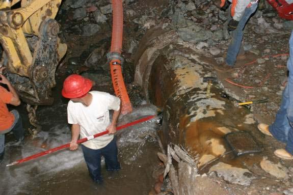
148 Examples of night work. 148

149 We welcome you to complete the assignment in Microsoft Word. You can easily find the assignment at Once complete, just simply fax or the answer key along with the registration page to us and allow two weeks for grading. Once we grade it, we will a certificate of completion to you. Call us if you need any help. If you need your certificate back within 48 hours, you may be asked to pay a rush service fee of $ You can download the assignment in Microsoft Word from TLC s website under the Assignment Page. You will have 90 days in order to successfully complete this assignment with a score of 70% or better. If you need any assistance, please contact TLC s Student Services. Once you are finished, please mail, or fax your answer sheet along with your registration form. 149
Two (2) Working Days before you dig, call Underground Service Alert at (811) or 1-(800)
 Working Days before you dig, call Underground Service Alert at (811) or 1-(800)") Chapter 11 Excavation & Trenching Chapter 11 - Excavation & Trenching Two (2) Working Days before you dig, call Underground Service Alert at (811) or 1-(800) 227-2600 Purpose The purpose of this policy
Chapter 11 Excavation & Trenching Chapter 11 - Excavation & Trenching Two (2) Working Days before you dig, call Underground Service Alert at (811) or 1-(800) 227-2600 Purpose The purpose of this policy
Title- Excavations Effective Date: 03 Jan 05 Revision-0
 Whaley Steel Corp Environment, Health & Safety Manual Section- 29.0 Title- Excavations Effective Date: 03 Jan 05 Revision-0 1.0 PURPOSE 1.1 This program outlines procedures and guidelines for the protection
Marshall Municipal Utilities EXCAVATIONS AND TRENCHING Effective August 1, 2011 Revised August 17, 2017
 Marshall Municipal Utilities EXCAVATIONS AND TRENCHING Effective August 1, 2011 Revised August 17, 2017 POLICY This policy applies to all open excavations and trenches; including those excavations and
Excavation and Trenching Safety Program
 Page 1 of 12 Sec: 1.0 PURPOSE 2.0 SCOPE This program outlines procedures and guidelines for the protection of employees working in and around excavations and trenches. This program requires compliance
Excavation and Trenching
 Excavation and Trenching Excavation and trenching are among the most hazardous construction operations. The Occupational Safety and Health Administration s (OSHA) Excavation standards, 29 Code of Federal
Purpose of Excavation Training
 EXCAVATIONS Purpose of Excavation Training Provide an overall awareness of hazards associated with excavation sites. Competent Person Underground Utility Lines Protective Systems (Sloping, Shoring, Shielding
TRENCHING AND EXCAVATION
 TRENCHING AND EXCAVATION The following guide is an aid intended for students who have completed the ClickSafety training course or module associated with Trenching and Excavation. This guide is a resource
Excavation &Trenching
 Excavation &Trenching The Hazards of Excavation and Trenching and How to Control Them Whitman College Department of Environmental Health & Safety and the Washington State Department of Labor & Industries
Excavation Safety Program
 Excavation Safety Program Excavation, Trenching & Shoring Safety I. Purpose The purpose of this policy is to establish safe operating procedures for any earthwork or underground work that is done on a
Excavation and trenching safety
 Excavation and trenching safety MNOSHA Compliance fatality investigations FFYs 2012 through 2016 During the period from Oct. 1, 2011, through Sept. 30, 2016, the annual average number of fatalities under
ESSENTIAL SAFETY RESOURCES
 ESSENTIAL SAFETY RESOURCES GS-3043 TRENCHING / SHORING / EXCAVATION PROGRAM Originator: Safety Advisor s Signature: Type Name Approval: HSE Manager s Signature: Type Name Approval: Operations Manager s
Trenching and Shoring Guidelines
 Trenching and Shoring Guidelines June 2018 TABLE of CONTENTS I. General II. Definition III. Requirements IV. Soil Types V. Test Methods and Evaluating Soil Types VI. Ingress and Egress VII. Exposure to
29 CFR 1926 Construction Subpart P
 Industry code # 1781 Water Well Drilling Special trade contractors primarily engaged in water well drilling. (Establishments primarily engaged in drilling oil or gas field water intake wells on a contract
!!! Sample Written Program For Your Company!!! Excavation Safety. 29 CFR 1926, Subpart P !!!!! Provided By:
 Sample Written Program For Your Company Excavation Safety Provided By: 29 CFR 1926, Subpart P P. O. Box 2136 Slidell, LA 70458 Phone: 985-781-1444 Fax: 985-718-4957 Email: info@se-safety.com 29 CFR 1926,
Trench Safety & Qualified Person Presented by: Mike Ross National Training Director
 Trench Safety & Qualified Person Presented by: Mike Ross National Training Director Excavation Hazards Excavation has always been dangerous work. Workers in the underground industry have a 112% better
SECTION TRENCH SAFETY PART 1 - GENERAL
 SECTION 31 41 33 - TRENCH SAFETY PART 1 - GENERAL A. This Section is intended to provide specifications for the minimum requirements for trench safety. The Contractor shall endeavor to insure the safety
Excavation and Trenching Program. Tampa Electric Company. Energy Supply
 Excavation and Trenching Program Tampa Electric Company Energy Supply Creation Date: 12/11/00 Maintained by: Date of last Modification: 05/07/02 Audience: All employees PURPOSE: The following guidelines
Risk Control at United Fire Group
 INTRODUCTION work can be a very hazardous exposure to employees and other contractors on construction job sites. is one of the most hazardous construction operations. The most feared hazard is excavation
Date Prepared: Location: Time: Approximate Temperature (degrees F): Weather Conditions: Project Name:
: Weather Conditions: Project Name:") Appendix C Hazard Assessment and Trench Entry and Authorization Form for regularly scheduled and emergency trenching activities Date Prepared: Location: Time: Approximate Temperature (degrees F): Weather
Appendix C Hazard Assessment and Trench Entry and Authorization Form for regularly scheduled and emergency trenching activities Date Prepared: Location: Time: Approximate Temperature (degrees F): Weather
Excavation & Trenching. A Trenching Tragedy
 Excavation & Trenching 1926 Subpart P A Trenching Tragedy False sense of security Knew they were out of compliance Thought the soil was stable Conditions changed overnight A worker died 1 What Is an Excavation
OUTLAW AUTOMATION INC. Safety Management System
 Preparation: Safety Mgr Authority: President Issuing Dept: Safety Page: Page 1 of 6 Purpose The purpose of this program is to provide employees general information for working on owner client or other
OKLAHOMA CITY COMMUNITY COLLEGE. Trenching and Excavation Safety Program
 OKLAHOMA CITY COMMUNITY COLLEGE Trenching and Excavation Safety Program Effective: April 20, 2012 1 Table of Contents Trenching and Excavation Safety Program I. Objective II. Assignment of Responsibility
Trenching & Shoring Safety Course Outline
 Trenching & Shoring Safety Course Outline The following outline summarizes the major points of information presented in the program. The outline can be used to review the program before conducting a classroom
Trenching and Shoring Safety in Construction Environments. Leaders Guide and Quiz
 Trenching and Shoring Safety in Construction Environments Leaders Guide and Quiz 4843 INTRODUCTION TO THE PROGRAM Structure and Organization Information in this program is presented in a definite order
RESOLUTION NO COL Excavation/TrenchingPolicy ADOPTING THE CAYUGA COUNTY EXCAVATION/TRENCHING SAFETY POLICY FOR COUNTY EMPLOYEES.
 RESOLUTION NO. 414-13 11-26-13 COL Excavation/TrenchingPolicy ADOPTING THE CAYUGA COUNTY EXCAVATION/TRENCHING SAFETY POLICY FOR COUNTY EMPLOYEES. BY: Hon. George Fearon, Chairman Government Operations
Weekly Safety Talks: Excavation & Trenching Application
 Weekly Safety Talks: Excavation & Trenching Application Review when we need to go into a trench. Ask can we do it any other way? Review soil types in the area and prevention methods preferred. Discuss
THE UNIVERSITY OF SOUTHERN MAINE (USM) Excavating/Trenching Program
 Excavating/Trenching Program") THE UNIVERSITY OF SOUTHERN MAINE (USM) Excavating/Trenching Program Department: University Environmental Health and Safety 2 TABLE OF CONTENTS Section Title Page 1.0 Scope 3 2.0 Program Requirements...
THE UNIVERSITY OF SOUTHERN MAINE (USM) Excavating/Trenching Program Department: University Environmental Health and Safety 2 TABLE OF CONTENTS Section Title Page 1.0 Scope 3 2.0 Program Requirements...
Excavation & Trench Safety 1
 Excavation & Trench Safety 1 Excavation Hazards 2 Cave-ins are the greatest risk Other hazards include: Asphyxiation due to lack of oxygen Inhalation of toxic materials Fire Moving machinery near the edge
WHITMAN COLLEGE TRENCHING AND SHORING PLAN
 Purpose: WHITMAN COLLEGE TRENCHING AND SHORING PLAN This is a statement of official college policy to establish the process for compliance with safety standards as stated in the Washington State Administrative
TRENCH SAFETY TRAINING
 TRENCH SAFETY TRAINING TRENCH SAFETY TRAINING TRENCHING ACCIDENTS ACCOUNT FOR MORE THAN 100 DEATHS A YEAR ON U.S. SOIL. 11 TIMES MORE WORKERS ARE INJURED 1% OF ALL CONSTRUCTION ACCIDENTS INJURY RATE FOR
DuPage County Environmental, Safety, Health & Property Loss Control Program Excavation & Trenching Confined Space Procedure
 1.0 Purpose: The purpose of this program is to establish guidelines to be followed to control excavation activities. All excavations will be done in full compliance of OSHA 29 CFR 1926.650, Subpart P.
Excavations. OSHA Office of Training and Education 1
 Excavations OSHA Office of Training and Education 1 Excavation Hazards Cave-ins are the greatest risk Other hazards include: Asphyxiation due to lack of oxygen Inhalation of toxic materials Fire Moving
DEPARTMENT OF LICENSING AND REGULATORY AFFAIRS DIRECTOR'S OFFICE CONSTRUCTION SAFETY STANDARDS PART 9. EXCAVATION, TRENCHING, AND SHORING
 DEPARTMENT OF LICENSING AND REGULATORY AFFAIRS DIRECTOR'S OFFICE CONSTRUCTION SAFETY STANDARDS (By authority conferred on the director of the department of licensing and regulatory affairs by sections
Operations: HSE. Ground Disturbance Safe Work Practice (SWP)
") Operations: HSE Ground Disturbance Safe Work Practice (SWP) AMENDMENT RECORD Amendment Date Revision Number Amender Initials 03/01/17 5 MB Amendment Practice is being reviewed with no changes to content.
Operations: HSE Ground Disturbance Safe Work Practice (SWP) AMENDMENT RECORD Amendment Date Revision Number Amender Initials 03/01/17 5 MB Amendment Practice is being reviewed with no changes to content.
OSH INFORMATION MEMORANDUM: 90-X-84. Inspection Procedures for Enforcing the Excavation Standard, Subarticle 7, 1926, Subpart C
 OSH INFORMATION MEMORANDUM: 90-X-84 TO: FROM: All OSH Compliance Personnel W. M. Lybrand DATE: June 1, 1990 SUBJECT: Inspection Procedures for Enforcing the Excavation Standard, Subarticle 7, 1926, Subpart
Excavations. OSHA (Revised)
") Excavations OSHA 2226 2002 (Revised) Contents Introduction... 1 What is the difference between an excavation and a trench?... 1 What are the dangers of trenching and excavation operations?... 1 OSHA s
Excavations OSHA 2226 2002 (Revised) Contents Introduction... 1 What is the difference between an excavation and a trench?... 1 What are the dangers of trenching and excavation operations?... 1 OSHA s
Excavation General Awareness Safety Training Presentation Red Willow Production Co.
 Excavation General Awareness Safety Training Presentation Red Willow Production Co. Learning Objectives Understand the purpose of our Excavation SOP - to protect employees and contractors when working
Excavation & Trenching Study Guide
 Excavation & Trenching Study Guide For XYZ Company Complies with Provisions of Excavations OSHA 29 CFR 1926.650 Subpart P Table of Contents Chapter Description Page 1. Introduction 3 2. Definitions 4 3.
To establish the Panama Canal Authority (ACP) occupational safety requirements for excavations.
 occupational safety requirements for excavations.") 1.0 PURPOSE To establish the Panama Canal Authority (ACP) occupational safety requirements for excavations. 2.0 BACKGROUND Excavation activities are highly dangerous and thus require adequate planning
1.0 PURPOSE To establish the Panama Canal Authority (ACP) occupational safety requirements for excavations. 2.0 BACKGROUND Excavation activities are highly dangerous and thus require adequate planning
(c) Presentation of Information. Information is presented in several forms as follows:
 Presentation of Information. Information is presented in several forms as follows:") CONSTRUCTION SEQUENCE FOR TIMBER SHORING FOR TRENCHES (a) Scope. This appendix contains information that can be used when timber shoring is provided as a method of protection from cave-ins in trenches
CONSTRUCTION SEQUENCE FOR TIMBER SHORING FOR TRENCHES (a) Scope. This appendix contains information that can be used when timber shoring is provided as a method of protection from cave-ins in trenches
Safety Meeting Topic #21 Trenches/Excavations
 Safety Meeting Topic #21 Trenches/Excavations Excavation and trenching cave-ins result in more than 100 fatalities annually in the United States. With little or no warning, an unsupported, improperly-shored
Central Washington University
 Central Washington University Excavation, Trenching and Shoring Program Plan prepared by: Central Washington University Office of Environmental Health & Safety 400 East University Way Ellensburg, WA 98926
Subpart P. Trenching & Excavating CLIENT SAFETY SERVICES
 Subpart P Trenching & Excavating CLIENT SAFETY SERVICES We typically start here 54 CLIENT SAFETY SERVICES Aren t Protective Systems Easier? CLIENT SAFETY SERVICES Begin with another end in mind Experience
THE UNIVERSITY OF SOUTHERN MAINE (USM) Excavating/Trenching Program
 Excavating/Trenching Program") THE UNIVERSITY OF SOUTHERN MAINE (USM) Excavating/Trenching Program Department: University Environmental Health and Safety 2 TABLE OF CONTENTS Section Title Page 1.0 Scope 3 2.0 Program Requirements...
THE UNIVERSITY OF SOUTHERN MAINE (USM) Excavating/Trenching Program Department: University Environmental Health and Safety 2 TABLE OF CONTENTS Section Title Page 1.0 Scope 3 2.0 Program Requirements...
MUNICIPALITY PERMIT Issued by the City of Holyoke 63 Canal Street, Holyoke, MA Phone (413) FAX (413)
 FAX (413)") MUNICIPALITY PERMIT Issued by the City of Holyoke 63 Canal Street, Holyoke, MA 01040 Phone (413) 322-5645 FAX (413) 539-6807 DPW OFFICIAL USE ONLY Permit Number Date Issued Expiration Date (If Applicable)
MUNICIPALITY PERMIT Issued by the City of Holyoke 63 Canal Street, Holyoke, MA 01040 Phone (413) 322-5645 FAX (413) 539-6807 DPW OFFICIAL USE ONLY Permit Number Date Issued Expiration Date (If Applicable)
TRENCH SAFETY FINAL EXAMINATION
 TRENCH SAFETY FINAL EXAMINATION 1. Trench accidents occur: a. Mostly in dry, compact soil b. Mostly in clay soil c. Mostly in wet soil d. Any type of soil 2. Trench collapse occurs: a. Over several days
Excavation Safety. May 2007
 May 2007 VIRGINIA POLYTECHNIC INSTITUTE AND STATE UNIVERSITY Excavation Safety Environmental Health and Safety Services Environmental Health and Safety Services Health and Safety Building 459 Tech Center
Excavation and Trenching
 Title: Excavation and Trenching Effective Date: 12/4/2014 Control Number: THG_0012 Revision Number: 1 Date: 10/10/2015 Annual Review Completed: 5/13/2015 Excavation and Trenching CONTENTS I. OBJECTIVE
Excavations. Department of Consumer & Business Services Oregon Occupational Safety & Health Division (OR-OSHA)
") Excavations Department of Consumer & Business Services Oregon Occupational Safety & Health Division (OR-OSHA) Preface This booklet provides an overview of the OR-OSHA standard on excavations, Division
Excavations Department of Consumer & Business Services Oregon Occupational Safety & Health Division (OR-OSHA) Preface This booklet provides an overview of the OR-OSHA standard on excavations, Division
Excavation and Trenching 2018 Stand Down. Jim Shelton, CAS Houston North Area Office
 Excavation and Trenching 2018 Stand Down Jim Shelton, CAS Houston North Area Office Why a Trenching Safety Stand Down? Workers Die and Get Injured Not All Publicity is Good Publicity BLS Fatalities by
RISK MANAGEMENT PROCEDURE
 RISK MANAGEMENT PROCEDURE SUBJECT: TRENCHING & SHORING SAFETY RULES R 6.0 EFFECTIVE: 06/13/01 REVIEWED: 1/15/18 I. PURPOSE The purpose of this procedure is to protect City employees who are required to
All employees who perform work which requires the removal of material that exceeds a depth of 1.2 meters (4 feet).
.") POLICY NO.: 12.4.6 EFFECTIVE DATE: January 26, 2004 PAGE: 1 OF 6 POLICY STATEMENT: Working in a trench can be hazardous. This policy, in combination with the Trenching, Shoring, and Excavating Program,
POLICY NO.: 12.4.6 EFFECTIVE DATE: January 26, 2004 PAGE: 1 OF 6 POLICY STATEMENT: Working in a trench can be hazardous. This policy, in combination with the Trenching, Shoring, and Excavating Program,
Trenching. 29 CFR Excavation Requirements. - Controls the trenching and excavation requirements for construction (excluding tunnels)
") 29 CFR 1926.651 Excavation Requirements - Controls the trenching and excavation requirements for construction (excluding tunnels) - Provides requirements for employee entrance, working environment, and
29 CFR 1926.651 Excavation Requirements - Controls the trenching and excavation requirements for construction (excluding tunnels) - Provides requirements for employee entrance, working environment, and
TRENCH SAFETY SPECIFICATIONS FOR THE DENTAL DEPOT CITY OF THE COLONY, TEXAS. Prepared for BLUESTONE PARTNERS. Project # 18115
 TRENCH SAFETY SPECIFICATIONS FOR THE DENTAL DEPOT CITY OF THE COLONY, TEXAS Prepared for BLUESTONE PARTNERS Project # 18115 US TREN-TECH, LLC 828 HOWELL DR. COPPELL, TEXAS 75019 TBPE#F9824 Anderson Consultant
Excavation Safety. Basic
 Excavation Safety Basic This course introduces the student to the safety hazards, precautions, and requirements within OSHA 1926, Subpart P, Excavations. This course provides general information about
Safety Overview. Falls Scaffolding Excavation. Risky Business. But is construction dangerous?
 Safety Overview Falls Scaffolding Excavation Risky Business Between 1980 and 1989, how many people died from occupational injuries? A. over 10,000 B. over 30,000 C. over 50,000 C is right: 63,589 died
The first line of defense from cave-ins: The Competent Person
 The first line of defense from cave-ins: The Competent Person Kathleen Henderson, Attorney, King & Ballow, Nashville, TN, ASSE member since 2002 Khenderson@kingballow.com Cave-ins remain a serious hazard
Tabulated Data Hydraulic Vertical Shores
 Tabulated Data Hydraulic Vertical Shores Revised June 1, 1999 Copyright, U.S.A.,Griswold Machine & Eng., Inc., 1998 594 West Highway M-60, Union City, MI 49094 (800) 248-2054 Fax: (517) 741-7483 CAUTION
Section 24 Brieser Construction SH&E Manual
 Section 24 Brieser Construction SH&E Manual June 7 2010 Excavating is recognized as one of the most hazardous construction operations. The primary hazards associated with excavations are the potential
Tabulated Data Waler Rails
 Tabulated Data Waler Rails Revised June 1, 1999 Copyright, U.S.A.,Griswold Machine & Eng., Inc., 1998 594 West Highway M-60, Union City, MI 49094 (800) 248-2054 Fax: (517) 741-7483 CAUTION EXCAVATION PROCEDURES
Section 24 Brieser Construction SH&E Manual
 Section 24 Brieser Construction SH&E Manual June 7 2010 Excavating is recognized as one of the most hazardous construction operations. The primary hazards associated with excavations are the potential
GROUND DISTURBANCE, TRENCHING, & EXCAVATING SAFE WORK PRACTICE 1.0 PURPOSE
 GROUND DISTURBANCE, TRENCHING, & EXCAVATING SAFE WORK PRACTICE 1.0 PURPOSE The purpose of the development of a standard excavation and shoring policy, practice and procedure is to enhance the level of
Excavation Safety. Standard Operating Procedures Summary
 Excavation Safety Standard Operating Procedures Summary Any employee performing excavation or trenching work at Liberty University must have as a minimum Awareness Level Training provided by the Health
EXCAVATION AND TRENCHING SAFETY REQUIREMENTS
 1.0 PURPOSE The purpose of this standard is to outline OSHA requirements as they apply to ecavations for Sierra Pacific Power Company s underground facilities. Facilitiy installation will not be accepted
Contents. Before you begin. Introduction: Installing trench support 1. Element 1: Planning and preparing 3
 Contents Contents Before you begin v Introduction: Installing trench support 1 Element 1: Planning and preparing 3 Section 1.1 Accessing, interpreting and applying compliance documentation 4 to the work
OSHA New Confined Space Rule
 OSHA New Confined Space Rule OSHA CLAIMS NEW CONFINED SPACE RULE WILL PREVENT 780 INJURIES A YEAR The Occupational Safety and Health Administration issued a final rule to increase protections for construction
Management of Health and Safety Risk Associated with Excavation Cave-in
 Management of Health and Safety Risk Associated with Excavation Cave-in Wellington Didi Thwala 1 1 Sustainable Human Settlement and Construction Research Centre, Department of Construction Management &
This data sheet discusses problems
 General excavation National Safety Council This data sheet discusses problems involved in general excavating operations where the excavation walls are vertical or nearly so, except shoreline excavating,
SAMPLE PAGES. Construction Safety and Health Program. [Company name]
![SAMPLE PAGES. Construction Safety and Health Program. [Company name]](/thumbs/95/123606731.jpg "SAMPLE PAGES. Construction Safety and Health Program. [Company name]") The safety and health of our employees is our top priority. Everyone goes home safe and healthy every day. Construction Safety and Health Program [Company name] [Date Authorized] [Version} 0 Contents Mission
The safety and health of our employees is our top priority. Everyone goes home safe and healthy every day. Construction Safety and Health Program [Company name] [Date Authorized] [Version} 0 Contents Mission
SECTION A1 EXCAVATION AND BACKFILL GENERAL
 SECTION A1 EXCAVATION AND BACKFILL GENERAL The work under this section shall include all excavation to such width and depth as shown on the drawings, specified herein, or ordered by the Engineer. Such
Start and Finish Dates: You will have 90 days from this date in order to complete this course
 Registration form OPERATOR MATH REVIEW $100.00 48 HOUR RUSH ORDER PROCESSING FEE ADDITIONAL $50.00 We will match any other price if you can find equivalent course for less. Start and Finish Dates: You
Aluminum Hydraulic Shoring
 AMERICA S TRENCH BOX BUILDER Aluminum Hydraulic Shoring EFFICIENCY PRODUCTION Hydraulic Shoring Tab Data Tabulated Data Effective January 4, 2010 Revised: October 28, 2014 - with CHANGE THREE America s
STANDARD PRACTICE INSTRUCTION
 STANDARD PRACTICE INSTRUCTION DATE: March 1, 2001 SUBJECT: Scaffolding Safety Program. REGULATORY STANDARDS: 29 CFR 1910.28 Safety Requirements For Scaffolding. 29 CFR 1910.29 Manually Propelled Mobile
Course 802. Excavation Safety
 Excavation Safety This page intentionally blank OSHAcademy Course 802 Study Guide Excavation Safety Copyright 2017 Geigle Safety Group, Inc. No portion of this text may be reprinted for other than personal
Hydraulic Aluminum Shoring
 AMERICA S TRENCH BOX BUILDER Hydraulic Aluminum Shoring Vertical Hydraulic Shoring System EFFICIENCY PRODUCTION, Hydraulic Shoring Tab Data - EU Units Edition Tabulated Data - EU Units Edition Effective
XXVI. Contractor Safety & Environmental Guidelines (For General Contractors and Sub-Contractors)
") XXVI. Contractor Safety & Environmental Guidelines (For General Contractors and Sub-Contractors) 1. PURPOSE 1.1 This procedure highlights minimum safe working practices required for all contractors working
XXVI. Contractor Safety & Environmental Guidelines (For General Contractors and Sub-Contractors) 1. PURPOSE 1.1 This procedure highlights minimum safe working practices required for all contractors working
SECTION EXCAVATING, BACKFILLING, AND COMPACTION FOR UTILITIES
 SECTION 02221 EXCAVATING, BACKFILLING, AND COMPACTION FOR UTILITIES PART 1 GENERAL 1.01 SUMMARY A. Related Sections: 1. 02200 - Earthwork. 2. 02660 - Water Systems. 3. 02720 - Storm Drainage System. 4.
Copies of the written program may be obtained at Where are copies of this written plan kept? (Insert building/room, etc.).
.") Scaffolding Safety Procedures for Construction Purpose It is this company's purpose in issuing these procedures to further ensure a safe workplace based on the following formal, written procedures for
Scaffolding Safety Procedures for Construction Purpose It is this company's purpose in issuing these procedures to further ensure a safe workplace based on the following formal, written procedures for
ITEM 481 MONOLITHIC REINFORCED CONCRETE BOX SEWERS
 AFTER FEBRUARY 1, 2011 ITEM 481 MONOLITHIC REINFORCED CONCRETE BOX SEWERS 481.1 Description. This specification shall govern for the construction of monolithic, reinforced concrete box sewers of the size,
Excavation Safety 6ES00-2.0
 Excavation Safety 6ES00-2.0 Associated OHS Process: General Industry and Construction Safety The master copy of this document resides in electronic format. Printed copies of this document are for convenience
ESSENTIAL STANDARD no.1. Excavations
 ESSENTIAL STANDARD no.1 Excavations KEY MESSAGES Ensure that public safety and the safety of those doing the work is the number one priority. Plan to use the best/correct method. For example, where space
Scaffolding Procedures
 Procedures Purpose It is the purpose of this company in issuing these procedures to further ensure a safe workplace based on the following formal, written procedures for scaffold work. Application This
Selection of Proprietary Shoring Equipment
 CPA Safety Guidance Selection of Proprietary Shoring Equipment Introduction Every contractor involved with groundwork must ensure the safe support of trenches and excavations as part of their risk assessment.
Supported Scaffold Inspections
 Supported Scaffold Inspections May 2016 Inspect scaffolds and scaffold parts daily, before each work shift, and after any event that may have caused damage. Check to see if power lines near scaffolds are
CHAPTER 3 EXCAVATIONS
 7-3-1 7-3-1 CHAPTER 3 EXCAVATIONS SECTION: 7-3-1: Permit Requirements 7-3-2: Bond Required 7-3-3: Subject and Excluded Excavations 7-3-4: Standards 7-3-5: Protection of Public 7-3-6: Relocation and Protection
Scaffolding Safety Procedures
 Safety & Health Program 10627 Midwest Industrial Boulevard, St. Louis, MO Phone: 314-785-6425 Fax: 314-785-6426 Scaffolding Safety Procedures Purpose It is this company's purpose in issuing these procedures
Effective Date: 10-January Table of Contents
 Version: 3 Page: 1 of 8 Table of Contents 1.0 Introduction... 2 1.1 Purpose... 2 1.2 Scope... 2 1.3 Definitions... 2 1.4 Responsibilities... 2 Environmental Health and Safety Office (EHSO) and Emory Healthcare
PACIFIC SHORING, LLC ALUMINUM SHORING PRODUCTS ALUMINUM S-PANEL SHIELDS. TABULATED DATA Effective April 01, 2014
 1 ALUMINUM S-PANEL SHIELDS Effective April 01, 2014 PSH 265 Roberts Avenue Santa Rosa, Ca. 95407 (707) 575-9014 Construction Engineering Resource 1837 Wright Street Santa Rosa, Ca. 95404 jmtengr2@aol.com
"CAUGHT-IN/BETWEEN HAZARDS IN CONSTRUCTION ENVIRONMENTS"
 PRESENTER'S GUIDE "CAUGHT-IN/BETWEEN HAZARDS IN CONSTRUCTION ENVIRONMENTS" Part of the "CONSTRUCTION SAFETY KIT" Series Quality Safety and Health Products, for Today...and Tomorrow OUTLINE OF MAJOR PROGRAM
provides a list of licensed on-site sewage designers.
 GRAYS HARBOR COUNTY DEPARTMENT OF PUBLIC SERVICES ENVIRONMENTAL HEALTH DIVISION 100 W Broadway Suite 31 Montesano, WA 98563 360-249-4222 360-249-3203 fax Fees: Alternative Sewage Disposal Permit (Pressure/Advanced
DOUBLE SLIDE RAIL INSTALLATION METHOD. Double Slide Rail August
 Double Slide Rail August 2015 1 DOUBLE SLIDE RAIL INSTALLATION METHOD Introduction Slide rail shoring systems can be used for trenches up to 12m wide and 6m deep. Module length is determined by panels
Required Courses $800/$720*
 1 Safety and Health Specialist (SHS) Construction Concentration Participants must complete a minimum of five (5) required and four (4) elective courses that include a minimum of 135 contact hours of training
1.01 GENERAL. l.02 PIPELINE TRENCH EXCAVATION PIPELINES AND STRUCTURES REVISION: SECTION 1 PAGE : 1-1
 1.01 GENERAL A. The Contractor shall perform all excavation, backfilling, grubbing and grading required for construction and installation of pipelines, structures and appurtenances. Excavation shall include
CODE OF PRACTICE EXCAVATION
 CODE OF PRACTICE EXCAVATION 2005 commission for occupational safety and health CODE OF PRACTICE EXCAVATION 2 0 0 5 Foreword The Occupational Safety and Health Act 1984 established the Commission for Occupational
JOB SAFETY ANALYSIS PROGRAM. Owner: Risk Management Revision No: 01. Document number: Q-001 Date last revised:
 Table of Contents 1.0 Applicability...2 2.0 Scope...2 3.0 Definitions...2 4.0 Core Information and Requirements...2 5.0 Roles and Responsibilities...6 6.0 Goals, Objectives and Performance Measures...7
To Loughborough University Facilities Management (FM) Health and Safety Policy
 Health and Safety Policy") Annex DD To Loughborough University Facilities Management (FM) Health and Safety Policy Work involving excavations Purpose According to the Occupational Safety and Health Administration (OSHA), the fatality
Annex DD To Loughborough University Facilities Management (FM) Health and Safety Policy Work involving excavations Purpose According to the Occupational Safety and Health Administration (OSHA), the fatality
Fall Protection Safety Program and Training Materials
 Prepared by Built Insurance Brokerage Fall Protection Safety Program and Training Materials Fall Protection Program... 1 Employee Fall Protection Flyer... 7 Fall Hazard Survey... 8 Requirements for Industrial
SECTION SOILS REPORT
 SECTION 02300 SOILS REPORT 1. GENERAL: 1.1 All work included under this heading shall be subject to the General Conditions of the entire operation. This Contractor is required to refer especially thereto.
Are designed to provide a safe working environment, and Govern use of fall protection procedures and equipment.
 Fall Protection Plan for Construction OSHA currently regulates fall protection for construction under Part 1926, Subpart M. The standards for regulating fall protection systems and procedures are intended
ilkti ...:- WOC LP Standards Section E005 - Excavation kj/0i DOCUMENT NO: WOC-HSE-ST-0001 & EP Department 44, 4R 11. C
 ...:- 44, 4R 11. C WOC LP & EP Department WOC HSE Standards Manual DOCUMENT NO: WOC-HSE-ST-0001 Section E005 - Excavation REV ISSUE PREPARED BY REVIEWED BY APPROVED BY ISSUE DATE 0 Issued for Use kj/0i