2.0 Project Description
|
|
|
- Shawn McCoy
- 6 years ago
- Views:
Transcription
1 2.0 Project Description 2.1 Existing Carlson Plant Site Location The Carlson Plant is located at 136 Steele Street in the City of Jamestown, Chautauqua County, New York. As shown on Figure 2.1-1, the Carlson Plant is bordered to the south by Steele Street, to the north by the Chadakoin River, to the west by Sprague Street, and to the east by the BPU office buildings, warehouses and garages. Access to the site is from Steele Street Combustion Units and Coal Handling System The Carlson Plant operates four pulverized coal-fired boilers (Nos. 9, 10, 11, and 12), along with auxiliary coal and ash handling equipment, a natural gas-fired combustion turbine with a heat recovery steam generator (HRSG) with supplementary-fired duct burners, and a small natural gas-fired auxiliary boiler. Boiler No. 11 has been in long-term lay-up since February The coal boilers and HRSG provide steam through a common header which can feed either one or both of the two steam turbine generators (Nos. 5 and 6), each rated at less than 25 MWe. A portion of the steam from the No. 6 turbine generator is also used to heat hot water for the District Heating System (see Section 2.1.5). The gas turbine can operate in either simple cycle mode (HRSG is bypassed and steam is not produced) or combined cycle mode (HRSG is used and steam is produced). Particulate emissions from the four boilers are controlled by individual electrostatic precipitators (ESPs). Two of the boilers, Nos. 9 and 12 (rated at 190 and 297 MMBtu/hr), are vented into a common stack, referred to as the North Stack (Emission Unit U-00003). The other two boilers, Nos. 10 and 11 (each rated at 190 MMBtu/hr), are vented into the South Stack (Emission Unit U-00004). The height of both stacks is 195 feet above grade. The natural gas-fired combustion turbine (General Electric LM6000) has a nominal capacity of 43 MWe and a heat input rate of 410 MMBtu/hr at International Standards Organization (ISO) conditions (ambient temperature of 59 o F, 60 percent relative humidity, and a pressure of 14.7 pounds per square inch). The HRSG has a natural gas supplemental duct burner rated at 144 MMBtu/hr. During simple cycle operation, heat from the gas turbine exhaust is not recovered in the HRSG. During combined cycle operation, the turbine exhausts through the HRSG. Steam generated in the HRSG is sent to the existing steam turbines to generate additional electricity as needed. The LM6000 combustion turbine and HRSG comprise Emission Unit U The BPU operates a small (23.3 MMBtu/hr) natural gas-fired boiler (Emission Unit U-00022) to supplement the district heating requirements. There are two other combustion sources at the Carlson Plant: a 500 kilowatt (kw) emergency diesel generator and a 750 kw emergency backup diesel-fired turbine that provides an emergency black start capability for the LM6000 turbine. The Carlson Plant burned 82,688 tons of bituminous coal in Approximately 90 percent of this amount was delivered to the site by truck, with the balance provided by rail. As shown in Figure 2.1-2, rail shipments of coal are unloaded at a rail siding located underneath the Third Street bridge (north of the Chadakoin River Q:\mw97\Projects\ \3390\Sec_2.doc 2-1 October 2006
2 and west of the Carlson Plant) onto trucks. The trucks then transport the coal to the site via Sprague and Steele Streets and dump the coal into a receiving hopper, which is enclosed on three sides and covered by a roof as shown in Figure Upon being dumped into a receiving hopper, the coal can be conveyed for immediate use into one of four bunkers with a total storage capacity of 1200 tons or be stored in a 4000 ton capacity silo. There is no open storage of coal. All coal transport within the plant is via totally enclosed conveyors. Air that is displaced by coal in the coal silo enters the conveyor system and is exhausted through a fabric filter (Emission Unit U-00008) Ash Handling System When pulverized coal is burned in a dry bottom boiler, about 80 percent of the unburned material or ash is captured and recovered as fly ash. The remaining 20 percent is dry bottom ash that collects in the bottom of the furnace. Figure is a schematic of the system used at the Carlson Plant to manage fly ash and bottom ash. As shown in Figure 2.1-4, both types of ash are conditioned with water prior to being discharged into trucks for off-site disposal. Fly ash collected in the bottom of the ESPs is conveyed pneumatically to the fly ash silo. The transport air of the pneumatic ash handling system is vented through a fabric filter (Emission Unit U 00007). The air that is displaced by the loading of fly ash and bottom ash into the fly ash and bottom ash silos is vented through fabric filters (Emission Units U and U-00006). The ash is beneficially used for mine reclamation in Pennsylvania (primary) or sent to the Chautauqua County Landfill (back-up) Power Generation The Electric Division of the BPU serves the City of Jamestown, the Villages of Celoron and Falconer, and portions of the Town of Ellicott. The winter peak electrical need in the BPU service area is approximately 100 MWe. This need is met through a combination of purchased hydroelectric power (over 80 percent) from the New York Power Authority and power generated by the Carlson Plant. The electricity produced by the Carlson Plant travels out to eleven neighborhood distribution substations located throughout the service territory at 13.8 kilovolts (kv). When the Carlson Plant is producing more power than is needed by its customers, the excess power is sent to the New York power grid over National Grid (formerly Niagara Mohawk) lines District Heating System The Carlson Plant also provides the thermal energy for the City of Jamestown s District Heating System. More than 70 customers representing a cross-section of businesses, industries, churches, schools, housing facilities, and not-for-profit agencies currently use approximately 16 megawatts thermal of district heating power. The system works as follows. A portion of the live steam generated by the coal boilers and the HRSG is extracted from the No. 6 turbine generator and is passed through a heat exchanger to thermally heat the water in the system. Steam from the main steam line to the steam turbine generators is used for an auxiliary topping heat exchanger that provides additional heat if required. During periods when the coal boilers and combustion turbine s HRSG are not operating, the auxiliary boiler is operated to heat the water. The heated water is sent through more than 11 miles of pipelines to the customers who use their own heat exchangers to draw energy from the water to heat buildings, provide domestic hot water, and for industrial purposes. The water returns to the plant to repeat the cycle Water Uses, Wastewater and Storm Water The current water requirements for the Carlson Plant are shown in Figure There are two sources of water: cooling tower make-up water is obtained from the Chadakoin River, and potable water is obtained from the City of Jamestown (BPU Water Division). Q:\mw97\Projects\ \3390\Sec_2.doc 2-2 October 2006
3 Steam generated by the boilers and the HRSG is condensed in a closed-loop system. In this system, water circulating through condenser tubes absorbs heat from the steam exhausted from the plant s steam turbines. The circulating water, which does not come in contact with the steam, is heated in the process of condensing the steam. The circulating water is sent to mechanical-draft cooling towers where the heated circulating water is cooled by being brought into direct contact with cooler ambient air. In the process, some water is evaporated into the air that flows through the cooling tower, sometimes resulting in the formation of a visible vapor cloud over the tower. The circulating water that is evaporated into the air must be replaced with fresh water; the source of this make-up water is the Chadakoin River. Moreover, the constant evaporation of circulating water concentrates solids in the water that remains in the closed-loop system, creating the need for water to be released, or blown down, from the system and replaced with fresh water (again, from the river) to maintain concentrations at acceptable levels. Water cascades down through the cooling tower into a cooling basin that is located on the BPU site and separated from the Chadakoin River. Make-up water is added to the cooling basin as needed to maintain the water level. The peak make-up rate is 1000 gallons per minute (gpm). The cooling tower system consists of a three-cell Foster Wheeler counterflow tower with two fans per cell and a two-cell Marley crossflow tower with one fan per cell. The Foster Wheeler towers have a designed drift elimination efficiency of 99.8 percent (i.e., 0.2 percent of the water flowing through the tower will escape the tower as drift droplets). The BPU recently replaced the single-cell Marley tower with the two-cell Marley tower. The new Marley tower, which became operational in mid-june 2005, has a designed drift elimination efficiency of percent (compared to 99.8 percent for the previous single-cell Marley tower). The water that is heated to steam in the boilers and HRSG must also be blown down to remove impurities. The make-up water for the coal boilers and the HRSG (approximately 27 gpm on average) and minor amounts of potable water for sanitary uses are obtained from the BPU s Water Division. The water is obtained from seven artesian wells located just north of Falconer that draw water from the Cassadaga aquifer. The BPU also operates four artesian wells in Poland Center, drawing water from the Conewango aquifer. These two aquifers have watersheds of 140 and 290 square miles, respectively. Operation of the Carlson Plant results in the generation of various wastewater streams, all of which are sent to BPU s Publicly Owned Treatment Works (POTW); i.e., the plant does not discharge any wastewater to the Chadakoin River. The largest of these streams is the blowdown from the cooling tower (peak rate of approximately 180 gpm). The majority of storm water generated on the Carlson Plant site is directed to the plant s cooling basin; i.e., it is not discharged to the Chadakoin River. There is a small area on the eastern side of the plant where storm water runoff from the plant drains off-site into existing storm sewers. The water combines with flow from other off-site drainage areas before discharging through underground piping to the Chadakoin River. Storm water generated at the existing railcar unloading area west of the Carlson Plant percolates into the surrounding ground (note that the coal is unloaded directly from the railcars to trucks for immediate transport to the Carlson Plant, i.e., there is no temporary placement of coal on the ground). 2.2 Proposed CFB Plant Overview The proposed CFB Plant is comprised of one CFB boiler, an advanced emissions control system, a fuel and ash handling system, a steam turbine generator with a net electrical output of approximately 43 MWe, supporting infrastructure, and connections to the district heating system. The design of the CFB boiler and supporting infrastructure is preliminary and will not be finalized until after the permitting process is completed. Q:\mw97\Projects\ \3390\Sec_2.doc 2-3 October 2006
4 Figure provides a preliminary site plan of the unit in relation to the existing Carlson Plant. A picture of a typical CFB boiler is provided in Figure A rendering of the proposed CFB plant superimposed in an existing aerial photograph of the Carlson Plant is provided in Figure A process flow diagram showing the primary inputs and outputs of the CFB plant is provided in Figure The CFB boiler and material storage area would be located east of the existing power plant buildings, in an area currently occupied by the BPU s office, garage, and warehouse buildings and parking area. The BPU currently uses land owned by the BPU on the south side of Steele Street for equipment storage, coal truck weighing, and vehicle fueling. The BPU would continue to use this area by the Carlson Plant after the Clean Coal Project became operational. The BPU intends to operate the CFB boiler as its base unit for electricity and district heat. Additional electrical and hot water needs would be met by operating the existing units. Existing coal-fired boilers Nos. 10 and No. 11 would be permanently shut down just prior to completion of the Project s shakedown period. There are significant advantages to locating the Clean Coal Unit on BPU property adjacent to the existing Carlson Plant. The use of this site would provide substantial additional efficiencies, in that it would enable the BPU to make use of existing infrastructure and staff. For example, existing coal handling facilities as well as the existing cooling towers and water systems could be reused for the CFB. In addition, the district heating and transmission and distribution infrastructures are already in place at the Carlson Plant and could be easily accessed to support the new plant. Because the area is primarily industrial and commercial, and a power plant is already located adjacent to the Clean Coal Unit site, the noise from the new plant would be consistent with existing conditions Fuel Specifications and Amounts In a CFB boiler, crushed coal and other fuels are mixed with limestone and fired in a process resembling a boiling fluid. The proposed CFB boiler has a maximum heat input rate of approximately 500 MMBtu/hr and would be capable of firing a mixture of fuels, including bituminous coal, petroleum coke, waste wood, and other opportunity fuels (including tire derived fuel, or TDF). The CFB boiler would have the capacity on a heat input basis to burn these solid fuels in various proportional combinations, including up to 100 percent coal, up to 100 percent petroleum coke, not more than 25 percent processed wood, and not more than 20 percent TDF. The approximate throughput values corresponding to these maximum proportional amounts for the above types of fuel are about 21.7 tons/hr for coal, 16.6 tons/hr for petroleum coke, 8.2 tons/hr for processed wood, and 3.6 tons/hr for TDF Fuel Delivery, Handling and Storage Delivery of the coal and petroleum coke fuels would be by truck and/or railcar. Truck delivery would utilize the existing scale, the existing coal receiving hoppers, and the existing belt conveyor system between the existing receiving hoppers and first transfer tower. The existing receiving hoppers are enclosed by a three-sided structure with a roof for weather protection and dust control. Railcar delivery would be at a new railcar unloading station (RUS) located along a rail siding on the north (opposite) side of the Chadakoin River across from the plant (shown in Figure 2.2-1, Area A). This new system would eliminate the need to transport the coal by truck from the current railcar unloading site to the Carlson Plant, thereby resulting in a significant reduction in noise impact and off-site fugitive dust associated with this activity. The new RUS would include an excavator with above grade hoppers for open-top railcar unloading. Stationary machinery and/or mobile equipment would be provided for moving and positioning railcars during unloading. Sufficient entry and exit track length would be provided at the RUS to manage block shipments of 1,000 tons (10 railcars at 100 tons each). Q:\mw97\Projects\ \3390\Sec_2.doc 2-4 October 2006
5 A flow diagram of the coal/petroleum coke processing system is provided in Figure A new (enclosed) belt conveyor system would be installed to transport the coal and petroleum coke above grade level from the new RUS on the north side of the river to the first transfer tower of the existing coal conveyor system on the south (plant) side of the river. Another new (enclosed) belt conveyor system would be installed to transport both truck and railcar delivered fuel (coal and petroleum coke) from that same existing transfer tower either to the new fuel (coal and petroleum coke) storage facilities, or directly to the boiler bunker in the new plant. The new coal/petroleum coke storage facilities would have a total fuel storage capacity of 5,000 tons, which includes one 1,000-ton silo and one 4,000-ton silo. The larger storage silo would have the capacity to feed the CFB at base load for approximately eight days. A new reclaim belt conveyor system would be provided to transport fuel from the two new silos to the bunker in the new plant. When burning a mixture of coal and petroleum coke, metering systems at each silo would be able to provide the desired ratio of coal and petroleum coke to the boiler bunker. A new crusher with bypass equipment would be installed in the new reclaim belt conveyor system to enable correct fuel sizing. All of the material handling components of the new fuel (coal and petroleum coke) handling systems would be designed for a conveying capacity of 250 tons/hr. Delivery of processed wood fuel would be by truck. The truck unloading station for this fuel would be located inside a new processed fuel storage building. The processed wood would be delivered properly sized for burning in the CFB boiler. A front-end loader would be used inside the storage building to place truck dumped fuel into a new receiving hopper. As shown in Figure 2.1-5, a new (enclosed) belt conveyor system would deliver the processed wood from the receiving hopper to a set of new live bottom metering bins located in the new plant. The metering bins would control the flow of fuel into the boiler. A new (enclosed) overage return belt conveyor system would be installed to return the overage of fuel that is not used by the metering bins back to the new fuel storage building. The processed wood fuel handling system would be designed for a conveying capacity of 10 tons/hr. The TDF also would be delivered by truck to the new processed fuel storage building. The TDF (as delivered) would be properly sized for burning in the CFB. The same new equipment (i.e., front-end loader, receiving hopper and supply/return belt conveyor systems) used for handling processed wood fuel would be used for handling the TDF Limestone Delivery and Storage The new CFB boiler would use crushed limestone to reduce sulfur dioxide (SO 2 ) and other acid gas emissions (including hydrogen chloride [HCl], sulfuric acid mist [H 2 SO 4 ], and fluorides [as HF]). The limestone would be added to the CFB boiler above the dense phase bed section of the boiler. The CFB boiler would be furnished with an 800-ton limestone storage silo inside the boiler house. The silo would be equipped with feeders for metering limestone to a pneumatic conveyor system that transports the limestone to the boiler. A new limestone handling system would be installed to receive delivery of high calcium limestone materials with a nominal top size of 1/8-inch and a moisture content of not more than one percent. A flow diagram of the system is shown in Figure The limestone would be delivered to the plant by tank trucks equipped for pneumatic unloading. A pneumatic conveyor system would be installed to transport the fine limestone from a new tank truck unloading station directly into the limestone storage silo. The trucks would connect to the pneumatic system intake pipe at grade level. The conveyor pipe run would extend from the truck unloading station to the conveyor discharge outlet at the top of the silo. The silo would be equipped with a bin vent filter for removing dust from the air that is used to convey the limestone to the top of the silo. The clean air from the bin vent filter would discharge to the atmosphere. The limestone handling system would be designed for a conveying capacity of 20 tons/hr. Q:\mw97\Projects\ \3390\Sec_2.doc 2-5 October 2006
6 2.2.5 Ash Generation and Handling When operating at full load, the CFB boiler would produce various ash residues at a combined rate of about 10 tons/hr. These ash residues would accumulate at three locations in the new plant: the fluid bed combustion chamber, the tubular air heater, and the baghouse. The ash handling system would include an ash collection system from various ash hoppers, an ash transport system, ash separation equipment, ash storage silos, and ash unloaders. Figure is a flow diagram of the ash handling system. The CFB boiler would have connections on the bottom of the dense phase fluid bed section to remove noncombustible materials and ash from the bed material. The ash from the dense phase bed would be very hot. The hot ash would be cooled using water-cooled screws that would transport the ash to bottom ash collection hoppers. This ash is referred to as bottom ash. Ash hoppers would be located under the tubular air heater to collect ash that falls out of the flue gas stream as it passes through the air heater. Ash hoppers would also be located under the baghouse to collect the ash that is removed from the flue gas that passed through the baghouse. The ash from the air heater hoppers and the baghouse hoppers is referred to as fly ash. There would be a separate bottom ash system, fly ash system and ash silos. The bottom ash silo would have a capacity of 300 tons. The fly ash silo would have a capacity of 600 tons. The bottom ash system would convey ash from the bottom ash collection hoppers to a bottom ash silo. The fly ash system would convey ash from the air heater hoppers and baghouse hoppers to a fly ash silo. The ash systems would have ash intake valves at each of the ash hopper outlet connections to control the flow of ash to the ash removal system. A control system would be included to control the ash intake valves automatically for the bottom ash and fly ash systems. The bottom ash system and fly ash system would operate independently. Separate conveying systems, silos and unloaders would be included for each system. The following equipment description is identical for the bottom ash and fly ash system. The ash transport system would include the ash pipe from each ash intake valve to the ash separating equipment located on top of the silo. A motor driven blower for the ash conveying system would be installed at the ash silo unloader floor. The blower would draw air through the ash transport piping system. When one of the ash valves is opened, the ash from the hopper would fall into the air stream in the ash pipe and be pneumatically conveyed to the ash separating equipment located on the top of the silo. The ash and air would pass through a bag filter/separator on the silo to remove the ash from the air stream. The ash would be discharged and collected in the silo. The blower would draw the air from the filter/separator. The air from the filter/separator would be monitored for dust and would shut down the system if dust was detected due to a broken bag. An outlet silencer would be installed on the discharge side of the blower to reduce noise. The discharge line from the blower would exhaust to atmosphere. Ash that is collected in the ash silos would be removed from the silo into trucks for disposal. The ash from each silo would be conditioned with water using a pugmill unloader to reduce dusting as the ash is removed. The unloading operation would take place within an enclosed building structure with roll-down doors. Air inside the building would be drawn through a bin vent filter and then discharged to the atmosphere. The BPU plans to return the ash produced by the CFB boiler to originating mines in Pennsylvania for beneficial reuse in the reclamation of those sites. In case of an emergency, the BPU would have limited space available at a local landfill, likely the Chautauqua County Landfill, to accept the ash. In addition, the BPU would work with the NYSDEC and the Pennsylvania Department of Environmental Protection (PADEP) to explore and develop beneficial re-uses for the plant volume as opportunities became available. Q:\mw97\Projects\ \3390\Sec_2.doc 2-6 October 2006
7 2.2.6 Air Pollution Control CFB Unit As discussed previously, limestone would be injected in the CFB combustion zone to remove sulfur oxides and other acid gases. NO x would be controlled by the CFB combustion process and through a selective noncatalytic reduction system (SNCR) that uses aqueous ammonia or urea. If aqueous ammonia was used, it would be stored in a 12,000-gallon (approximate) tank. If urea was used, it would either be delivered and stored in aqueous form (40 percent solution) or be generated on-site from powdered urea and water. The combustion gases would then pass through a fabric filter baghouse for control of particulate matter before being vented to a new 320-foot high stack Material Handling System Bin vent filters (small fabric filter baghouses) would be used at the RUS, processed material building, ash silos/handling building, and transfer points on the fuel and ash conveyor systems to control particulate matter emissions. The design outlet grain loading for all filters would be grains per cubic foot (gr/cf) of air flow through the filter (one grain equals pounds). There would be no open storage of fuel or ash and all conveyors would be enclosed. The locations of the bin vent filters are shown in Figure Continuous Emissions Monitoring System A continuous emissions monitoring (CEM) system consisting of stack flue-gas probes would be located in the CFB stack. A data-acquisition system would receive signals from the stack probes. The system would include gas analyzers and monitors that process the data. The BPU anticipates that continuous monitoring of NO x, SO 2, carbon monoxide (CO), mercury and CO 2 emissions as well as opacity, flue gas flow, steam production, and electrical generation would be conducted to ensure continuous compliance with emission limitations of these compounds. Compliance with emission limits for particulate matter sized 10 microns (µm) and less (PM 10, also referred to as inhalable particulate matter), volatile organic compounds (VOCs), and H 2 SO 4 would be demonstrated after the completion of the start-up period by a stack testing program in accordance with federal and state requirements. (One micron is equal to one-thousandth of a millimeter or 4/100,000-ths of an inch.) Compliance with the particulate matter emission limits would be based either on continuous emissions monitoring or on periodic stack testing Power Generation The CFB boiler would provide steam at 1500 pounds per square inch at gauge (psig) and 950 degrees Fahrenheit ( o F) to a new steam turbine generator set to produce up to 43 MWe (net). The integration of the CFB Plant with the existing Carlson Plant is shown in Figure The new CFB Plant would utilize the generator unit connected concept. This plan would require the installation of three transformers, each of which would be located outside: Generator Step-up Transformer kv/13.8 kv Running Auxiliary Power Transformer kv/4.16 kv Start-up Auxiliary Power Transformer kv/4.16 kv The new steam turbine generator would be connected to the new 34.5 kv switchgear via the Generator Stepup transformer. The new 34.5 kv switchgear would be located inside the new CFB plant. There would be one Q:\mw97\Projects\ \3390\Sec_2.doc 2-7 October 2006
8 34.5 kv underground circuit connecting the new 34.5 kv switchgear to the existing power plant 34.5 kv switchgear. The new steam turbine generator would also be connected to the Running Auxiliary Power transformer. The boiler-generator unit would be started from the Start-up Auxiliary Power transformer and when the generator was on line, the auxiliary power would be transferred to the Running Auxiliary Power transformer. This would provide for a higher overall auxiliary power system efficiency as the running auxiliary power would not need to be stepped up through the generator step-up transformer Interconnection with Existing District Heating System The new steam generator unit would provide a new source for heating the district hot water system. As shown in Figure 2.2-9, the steam turbine generator would have a controlled steam extraction port designed to provide 80 MMBtu to the district heating system. A heat exchanger would be used to transfer heat from controlled extraction steam to the hot water district heating system. New hot water piping would be constructed from the new heat exchanger to the existing main district heating system piping which is located at the Carlson Plant Water Uses, Wastewater and Storm Water Steam generated by the CFB boiler would be condensed by the existing closed-loop system and cooling towers. Figure is the current and future circulating water flow diagram for the facility. The CFB Plant would utilize the new two-cell Marley tower to the extent possible. The portion of the circulating water from the CFB Plant s condenser cooling water system that could not be handled by the new Marley tower would be sent to the existing Foster Wheeler tower. Figure is a water balance diagram showing the projected total water requirements for the Carlson Plant after implementation of the CFB Plant. The CFB unit, by itself, would require approximately 560 gpm of makeup water for the cooling tower from the Chadakoin River and up to an additional 96 gpm of potable water from the BPU s Water Division. The BPU proposes to use the same intake screen system that is currently in use at the Carlson Plant (i.e., an outer 5/8-inch mesh screen and an inner 3/8-inch mesh screen). Wastewater from the CFB Plant, including approximately 153 gpm cooling tower blowdown attributable to the CFB unit, would be integrated with the wastewater streams from the existing Carlson Plant prior to discharge to the POTW. Storm water from the CFB Plant site (both north and south of the Chadakoin River) would be managed in a manner consistent with NYSDEC storm water management guidelines. The BPU is proposing to convey storm water on the portion of the CFB Plant site located south of the Chadakoin River to the cooling tower basin. The BPU proposes to direct storm water runoff that exceeds the capacity of the cooling tower basin to a proposed new outfall on the Chadakoin River. Refer to Section for additional discussion of storm water management Operations Steady-State Operations The BPU expects to operate the CFB boiler as a base load unit. The CFB boiler would operate close to its design heat input (i.e., 500 MMBtu/hr) during the winter when district heating needs are the greatest. Steadystate operation is defined as the operation of the boiler on solid fuel only at and above the minimum operating load of 200 MMBtu/hr heat input (40 percent of maximum load). Q:\mw97\Projects\ \3390\Sec_2.doc 2-8 October 2006
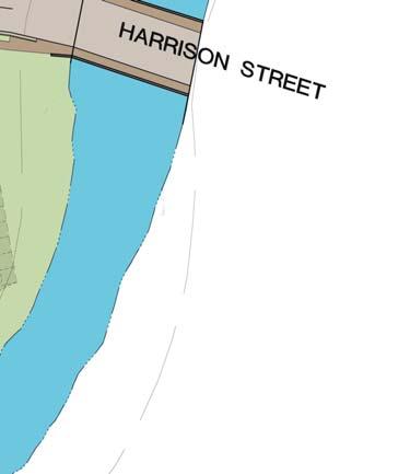
9 Start-up and Shutdown The temperature of the bed material must be raised sufficiently to allow solid fuel ignition. This heating would be accomplished by firing natural gas in two burners located in the CFB furnace. The two burners would have a total heat input rate of 200 MMBtu/hr. The burners would be fired until the coal feed rate is established and stable. The BPU anticipates that the maximum duration of a cold start-up under normal conditions would be 16 hours. Limestone and aqueous ammonia would not be injected for control of SO 2 and NO x emissions, respectively, until the CFB unit has reached the appropriate temperature ranges. Injection could not occur prior to this point because of the potential undesired effects of low furnace temperatures. Shutdown of the CFB unit would be initiated by shutting off the fuel supply. The air flow would be maintained to cool the unit or shut off to preserve the heat for a warm or hot re-start. On an orderly load reduction, 50 percent load would be reached in approximately 15 minutes from full load. At that point, both limestone and aqueous ammonia or urea injection would be stopped. 2.3 Service Facilities Existing Service Facilities The existing BPU service facilities are currently located east of the existing Carlson Plant at Steele Street as shown in Figure These facilities house the BPU s general business offices, maintenance operations (garages and warehouses), the Customer Service Center, and a storage area for electrical equipment (transformers, poles, spools of wire, etc.). Currently, approximately 120 customers, 110 office and maintenance workers, and 60 trucks travel to and from the Steele Street service facilities on a daily basis. This building is open typically between 6AM and 6PM, Monday through Friday. Once the BPU has moved into the new Operations Center, the existing Steele Street service facilities will be demolished to make room for the clean coal unit New Operations Center Location and Access The proposed site for the new Operations Center is located on Harrison Street between Winsor Street and Foote Avenue, approximately 1.0 mile east of the Carlson Plant. The site is bounded on the west by Phoenix Metal Manufacturing Co., on the north by the railroad tracks, on the east by Winsor Street and on the south by the Chadakoin River. The location of the proposed site relative to the existing Steele Street facility is shown in Figure The primary intersection that would provide access to the site is Winsor and Harrison Streets as shown in Figure The BPU anticipates that the Operations Center would be open from 6AM to 6PM, Monday through Friday (i.e., same as for the existing service facilities). Approximately 285 vehicles per day are expected to travel to and from the Operations Center (i.e., the same number of vehicles currently accessing the existing service facilities) Proposed Facilities The proposed new BPU Operations Center is comprised of an office facility that is anticipated to be a twostory, 15,380 square foot structure for administrative offices and an additional 18,410 square foot structure for Q:\mw97\Projects\ \3390\Sec_2.doc 2-9 October 2006
10 engineering and technical offices. The building would not have a basement. Adjoining the office building would be a 20,754 square foot garage building. Employee and customer paved parking areas would be located adjacent to the buildings on the east side of the Operations Center. Future parking, if needed, would be made available on the south side of Harrison Street. Adjacent to the building to the west would be an outdoor storage area for transmission poles, transformers, spools of wire, and other related equipment. The area south of Harrison Street and west of the parking lot would be used for additional storage and lay-down. The BPU might consider future improvements to the Chadakoin River front adjoining this site. Figure is a conceptual site plan for the proposed Operations Center. A rendering of the proposed Operations Center is shown in Figure Storm water from the site would be conveyed to the existing storm sewer system near Harrison Street. The BPU plans to make the Operations Center a demonstration project for sustainability and energy efficient technologies. The project would demonstrate how proper technologies and building design could both reduce energy consumption and be environmentally friendly. Some of these technologies include: District Heating and absorption cooling from District Heat; the utilization of enhanced building envelope design to provide increased insulation and passive solar gain; day lighting techniques to reduce lighting and cooling loads; energy efficient lighting; heat recovery; and innovative building controls to increase energy efficiency as well as other energy efficiency technologies. The building would also utilize local materials and products with high recycled content. The BPU would pursue LEED (Leadership in Energy and Environmental Design) certification from the U.S. Green Buildings Council Site Description The site of the proposed Operations Center is comprised of 10 separate parcels of land totaling approximately 8.21 acres. The Chautauqua County Industrial Development Agency owns 3.64 acres of the properties that are needed for the Operations Center. The Jamestown Board of Public Utilities recently voted to purchase six parcels of land from four owners. The majority of the site is devoid of vegetation and is abandoned. There are three structures located on the site that would have to be removed. The structure located to the far east of the property is a warehouse on the site of a former lumber firm (which has been shut down for over 30 years). The structures located along Harrison Street include a residence that housed a bar/restaurant as well as an apartment and a second house. The proposed site of the Operations Center is located southeast of the urban center of the City of Jamestown. The area surrounding the site is primarily industrial. There are commercial/industrial properties, vacant properties, and some limited residential properties in the general vicinity of the site. A significant percentage of the commercial/industrial properties are unoccupied or underutilized. The site is relatively flat, with average elevation of 1,310 feet above mean sea level (ft msl). The elevation is higher where the Operations Center building and other developed sections would be located and lower in the areas that would remain undeveloped near the Chadakoin River waterfront. The building site is vacant and attempts to develop it have been on-going for the past eight years. Semi-trailer storage exists on several parcels. BPU storage is presently located next to the vacant bar / restaurant / residence Utility Interconnections The proposed Operations Center would interconnect with utilities located in the area, including water, sewer, and electric, which are located in or near Harrison Street, adjoining the site. The proposed Operations Center Q:\mw97\Projects\ \3390\Sec_2.doc 2-10 October 2006
11 would also interconnect with the BPU s District Heating system. Natural gas, if needed at the Operations Center, would be obtained from the local distribution system. 2.4 Construction Construction Schedule The proposed site of the Clean Coal Unit is currently occupied by buildings owned by the BPU which house the BPU offices and various BPU service departments. There are also paved driveways, parking areas, and a storage area for electrical equipment, primarily pad and pole mounted transformers, on the site. Construction of the new plant will require the demolition and removal of the existing buildings and other site paving and improvements. The new operations center must be constructed and the personnel and departments and electrical equipment moved to the new location before the existing buildings can be demolished. The BPU plans to commence construction of the Operations Center once all of the necessary permits and approvals have been obtained. The preliminary schedule anticipates that the construction contract would be awarded in January 2007 and that the BPU personnel would move in between May and June If this preliminary schedule holds, the existing buildings on Steele Street would be ready for demolition during the latter part of the second quarter Construction of the Clean Coal Unit would commence mid-2008 once demolition activities are complete. Based on this start date, the BPU anticipates that the Clean Coal Unit would be commercially available in mid Construction is expected to take place typically between 7AM and 6PM, Monday through Saturday. However, in order to meet the above schedule, the BPU anticipates that there might be occasions when it would be necessary for construction activities to start as early as 6AM and to finish by 11PM; construction on some Sundays might also be necessary. In addition, on isolated occasions, certain construction activities (e.g., concrete pours) might require continuous operation over a 24-hour period Construction Activities and Workforce New Operations Center The proposed Operations Center and related development are not within the 100-year floodplain associated with the Chadakoin River. A small portion of the site that borders the Chadakoin River is located within the 100-year flood plain (see Figure 2.3-4). This area would remain undeveloped. Excavation would be required for building foundations and underground utilities. The BPU does not anticipate the need for any rock excavation or blasting during the demolition or excavation work. During peak construction activities, the BPU anticipates that there would be approximately 75 construction workers. Construction lay-down space and parking will be located on areas owned by the City in the vicinity of the site CFB Plant Following the relocation of personnel, offices and equipment to the new Operations Center, the existing corporate office building, warehouses and garages would be demolished 1. After the demolition and debris removal work was completed, there would be minimal additional site preparation work required for the CFB Plant. The site is currently flat and reasonably level, varying by approximately 2 feet in elevation from the east 1 The BPU might start construction on certain components of the CFB Plant (e.g., the rail unloading station) prior to demolition of the existing office building complex. Q:\mw97\Projects\ \3390\Sec_2.doc 2-11 October 2006
12 end of the site to the west end, a distance of approximately 1000 feet. However, the site is bounded on the south by Steele Street, which is approximately 10 feet higher in elevation than the site. To maximize the usable area at the site, a new retaining wall could be constructed along the south edge of the site, just north of Steele Street. Excavation would be required for building and equipment foundations, utilities, circulating water lines, cooling tower basin expansion, etc. However, there would not be any large, deep excavations because there would be no basements in any of the new buildings. It is anticipated that the foundations for the buildings, silos, stack, baghouse, and transfer towers will all be supported on driven steel piles or caissons. The BPU does not anticipate the need for any rock excavation or blasting during the demolition or excavation work. The BPU, in concert with the construction contractor, would select the areas for construction laydown, staging and parking. These areas would include the construction site itself, the BPU owned area south of the site across Steele Street where the existing BPU truck scales and BPU Water Department s fueling station are located, and other off site locations. Note that the truck scales and fueling station across Steele Street from the site would continue to remain in service during the construction period. Contractor trailers would be located either in the designated areas south of Steele Street or at the east end of the construction site. There would be minimal on-site parking, and that would be available only at the contractor trailer areas. The approximate manpower requirements during the CFB Plant construction period is shown in Figure During peak construction activities, the BPU anticipates that there would be approximately 200 construction workers. Potential parking could be available at City owned parking garages and surface lots, including five surface lots and one parking ramp (totaling 465 spaces) on a first-come, firstserved basis. The City also has an additional 209 on-street metered spaces located primarily downtown. So as not to interfere with existing downtown parking arrangements, the BPU could also work with other entities, as shown on Figure 2.4-2, to provide construction parking with the contractors providing transportation for the construction workers between the various parking areas and the construction site. The BPU anticipates that approximately acres would be needed for construction laydown and staging. There is not sufficient space available at Steele Street to accommodate this need. Areas for long-term laydown and staging of materials and equipment would be selected based on ease of access from major transit routes (e.g., Interstate 86, State Route 60, etc.). Short-term storage, laydown, and staging of materials and equipment would be in limited areas designated on the site and in the area across Steele Street south of the site. Q:\mw97\Projects\ \3390\Sec_2.doc 2-12 October 2006


13 Figure Aerial View of Carlson Plant Q:\mw97\Projects\ \3390\Sec_2 figures.doc October 2006

14 Figure Current Method of Unloading Rail Shipments of Coal for the Carlson Plant Q:\mw97\Projects\ \3390\Sec_2 figures.doc October 2006

15 Figure Carlson Plant Coal Receiving Hopper Q:\mw97\Projects\ \3390\Sec_2 figures.doc October 2006
16 Figure Carlson Plant Ash Handling System Flow Diagram Q:\mw97\Projects\ \3390\Sec_2 figures.doc October 2006
17 Figure Water Balance Diagram - Current Carlson Plant Q:\mw97\Projects\ \3390\Sec_2 figures_11x17.doc October 2006
18 Figure Site Plan for CFB Plant Q:\mw97\Projects\ \3390\Sec_2 figures_11x17.doc October 2006


19 Figure Picture of a Typical Circulating Fluidized Bed Boiler Q:\mw97\Projects\ \3390\Sec_2 figures.doc October 2006

20 Figure Rendering of the Proposed CFB Plant Q:\mw97\Projects\ \3390\Sec_2 figures.doc October 2006

21 Figure Process Flow Diagram for the Proposed CFB Plant Q:\mw97\Projects\ \3390\Sec_2 figures.doc October 2006

22 Figure Coal/Petroleum Coke Processing System Flow Diagram for CFB Plant Q:\mw97\Projects\ \3390\Sec_2 figures_11x17.doc October 2006
23 Figure Limestone Handling System Flow Diagram for CFB Plant Q:\mw97\Projects\ \3390\Sec_2 figures_11x17.doc October 2006
24 Figure Ash Handling System Flow Diagram for CFB Plant Q:\mw97\Projects\ \3390\Sec_2 figures_11x17.doc October 2006
25 Figure Location of Material Handling System Bin Vent Filters for CFB Plant Q:\mw97\Projects\ \3390\Sec_2 figures_11x17.doc October 2006
26 Figure Power Generation Cycle Diagram with CFB Plant Q:\mw97\Projects\ \3390\Sec_2 figures_11x17.doc October 2006
27 Figure Circulating Water System with CFB Plant Q:\mw97\Projects\ \3390\Sec_2 figures_11x17.doc October 2006
28 Figure Water Balance Diagram - with the CFB Plant Q:\mw97\Projects\ \3390\Sec_2 figures_11x17.doc October 2006


29 .3-1

30 2.3-2

31 2.3-


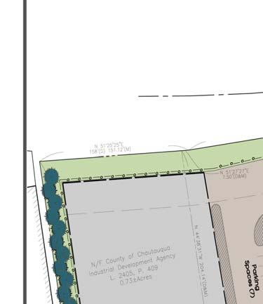
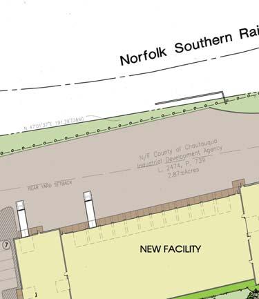

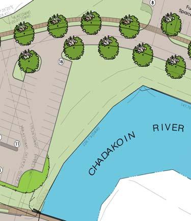

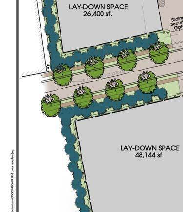


32 Figure Proposed BPU Operations Center Conceptual Site Plan M060014_E
33 Figure Rendering of the Proposed New Operations Center Q:\mw97\Projects\ \3390\Sec_2 figures.doc October 2006
34 Figure Anticipated CFB Plant Construction Manpower Loading No. of On Site Workers Months Q:\mw97\Projects\ \3390\Sec_2 figures.doc October 2006

 property J Jones &")


35 Figure Potential Construction Parking Locations Key to sites: A Bergman Park E former Unloading Corp I Jock Shop parking lot B New Heights Methodist Church F Erie RR (Norfolk Southern) property J Jones & Gifford Substation C Jones Hill Memorial Hospital G Erie Railroad Station & Washington Street Substation K Monroe Street city properties D beneath the New York State DOT 3 rd Street Bridge H behind Blackstone-Ney Ultrasonics; L Chadakoin Park parking lot M former Big N parking lot Q:\mw97\Projects\ \3390\Sec_2 figures_11x17.doc October 2006
New 790-Megawatt Unit. Council Bluffs Energy Center
 New 790-Megawatt Unit Council Bluffs Energy Center JUST THE FACTS Council Bluffs Energy Center s New 790-Megawatt Unit Background To ensure a long-term positive impact on Iowa's economy and a secure supply
CCR Fugitive Dust Control Plan
 CCR Fugitive Dust Control Plan Mill Creek Generating Station Louisville Gas & Electric Company Jefferson County, Kentucky October 2015 CCR Fugitive Dust Control Plan - Mill Creek Generating Station Page
Michigan Department of Environmental Quality - Air Quality Division ADDITIONAL TECHNICAL INFORMATION FOR BOILERS
 Michigan Department of Environmental Quality - Air Quality Division ADDITIONAL TECHNICAL INFORMATION FOR BOILERS The following information will be used for the technical review of a permit to install application
Borregaard Case Study. Sarpsborg I & II
 Borregaard Case Study Sarpsborg I & II Borregaard Case Study Sarpsborg I & II Situation Borregaard Industries is a major supplier of wood-based chemicals. The company owns and operates one of the world
CCR COMPLIANCE FUGITIVE DUST CONTROL PLAN. Prepared for: Tucson Electric Power Company Springerville Generating Station Springerville, Arizona
 CCR COMPLIANCE FUGITIVE DUST CONTROL PLAN Prepared for: Tucson Electric Power Company Springerville Generating Station Springerville, Arizona Prepared by: CB&I Environmental & Infrastructure, Inc. Pittsburgh,
PUBLIC SERVICE COMPANY OF OKLAHOMA (PSO)
") PUBLIC SERVICE COMPANY OF OKLAHOMA (PSO) NORTHEASTERN POWER STATION ANNUAL CCR FUGITIVE DUST CONTROL REPORT Prepared By: Public Service Co. of Oklahoma 7300 East Highway 88 Oologah, OK 74053 and American
PUBLIC SERVICE COMPANY OF OKLAHOMA (PSO) NORTHEASTERN POWER STATION ANNUAL CCR FUGITIVE DUST CONTROL REPORT Prepared By: Public Service Co. of Oklahoma 7300 East Highway 88 Oologah, OK 74053 and American
VIRIDOR WASTE MANAGEMENT ARDLEY EFW PLANT EP APPLICATION - NON TECHNICAL SUMMARY
 VIRIDOR WASTE MANAGEMENT ARDLEY EFW PLANT EP APPLICATION - NON TECHNICAL SUMMARY S1014-0340-0008MPW NTS Rev1.doc Print Date 19 February 2009 ISSUE NUMBER 1 DATE 19/02/09 AUTHOR CHECKED MPW SMO Title Page
High Bridge Combined Cycle Plant
 High Bridge Combined Cycle Plant Location: Down town St. Paul, on the Mississippi River Plant Description: High Bridge is a combined cycle generating facility. A combined cycle plant produces electricity
Refuse-to-Energy Facility
 Commerce Refuse-to-Energy Facility Waste Diversion: A Challenge for Southern California Communities Los Angeles County successfully diverts more than 50 percent of the solid waste generated each day from
STATEMENT OF BASIS. Cheney Lime & Cement Company Landmark Plant Alabaster, Alabama Shelby County Facility No
 STATEMENT OF BASIS Cheney Lime & Cement Company Landmark Plant Alabaster, Alabama Shelby County Facility No. 411-0019 This proposed Title V Major Source Operating Permit (MSOP) renewal is issued under
INDUSTRIAL ACCESSORIES COMPANY
 INDUSTRIAL ACCESSORIES COMPANY Industrial Accessories Company is an industrial design/build and original equipment manufacturer of baghouses, flue gas desulfurization, heavy metal mitigating sorbent injection
2. How can the University have an expansion of the Cogeneration Facility without an increase in the amount of coal used?
 Responses to Questions Raised at the November 9, 2005 Public Hearing on the University of North Carolina at Chapel Hill s Special Use Permit Modification Request 1. What is the nature of the surveying
SUMMARY OF COMMENTS/RECOMMENDATIONS
 SUMMARY OF COMMENTS/RECOMMENDATIONS PROPONENT: Boulet Brothers Concrete Ltd. PROPOSAL NAME: Ste. Agathe Concrete Batch Plant CLASS OF DEVELOPMENT: 1 TYPE OF DEVELOPMENT: Concrete Batch Plant CLIENT FILE
Wellington Development WVDT, LLC Greene Energy Resource Recovery Project 3. GENERAL CONDITIONS
 3. GENERAL CONDITIONS 2 a) This Plan Approval authorizes the construction of two waste coal-fired, circulating fluidized bed (CFB) boilers and a steam generator capable of producing 580 gross megawatts
On-Line Carbon in Ash System at PPL Montour for Increasing Ash Sales
 2013 World of Coal Ash (WOCA) Conference - April 22-25, 2013 in Lexington, KY http://www.flyash.info/ On-Line Carbon in Ash System at PPL Montour for Increasing Ash Sales Todd Melick 1, Larry LaBuz 2,
2015 ANNUAL ENGINEERING INSPECTION REPORT PLUM POINT ENERGY STATION CLASS 3N LANDFILL PERMIT NO S3N AFIN:
 2015 ANNUAL ENGINEERING INSPECTION REPORT PLUM POINT ENERGY STATION CLASS 3N LANDFILL PERMIT NO. 0303-S3N AFIN: 47-00461 JANUARY 15, 2016 PLUM POINT ENERGY STATION CLASS 3N LANDFILL 2015 ANNUAL ENGINEERING
Conceptual Facility Plans and Details. Appendix B
 Conceptual Facility Plans and Details Appendix B Process Flow Diagrams and Equipment ³ ³ ³ ³ ³ PRELIMINARY / CONCEPTUAL 740 SOUTH SYNDICATE AVENUE THUNDER BAY, ONTARIO P7E 1E9 www.genivar.com TEL: 807
Fluid Bed Scrubbing TECHNOLOGY
 CIRCULATING Fluid Bed Scrubbing TECHNOLOGY Circulating fluid bed scrubbing technology is a flexible multi-pollutant technology quickly gaining recognition. >> BY BOB GIGLIO, VICE PRESIDENT OF STRATEGIC
Ms.P.Aileen Sonia Dhas
 SUBJECT CODE SUBJECT NAME STAFF NAME : ME8792 : Power Plant Engineering : Prof.V.Tamil Selvi Ms.P.Aileen Sonia Dhas UNIT- I COAL BASED THERMAL POWER PLANTS Rankine cycle - improvisations, Layout of modern
Columbia, Missouri, Manufactured Gas Plant Project Fact Sheet: August 2013
 Columbia, Missouri, Manufactured Gas Plant Project Fact Sheet: August 2013 Ameren Missouri is committed to keeping customers informed about planned work at the Ameren Missouri service center property at
Industrial Accessories Company 4800 Lamar Ave Mission, Kansas ETHANOL MARKET. PP007
 Industrial Accessories Company 4800 Lamar Ave Mission, Kansas 66202 ETHANOL MARKET PP007 1 PRODUCTS & SYSTEMS 1. OEM Baghouse Supplier. 2. FGD Technology for SOx & HCL Removal 3. Fly-ash & Material Pneumatic
17.0 INFRASTRUCTURE AND ENERGY
 17.0 INFRASTRUCTURE AND ENERGY The Project would place demands on the existing infrastructure systems for supplying water, treating sewage, providing energy and disposing of solid waste. The Project would
PLANNED UNIT DEVELOPMENT & PLANNING APPROVAL STAFF REPORT Date: February 7, 2013
 PLANNED UNIT DEVELOPMENT & PLANNING APPROVAL STAFF REPORT Date: February 7, 2013 NAME LOCATION MAWSS Shelton Beach Road East side of Shelton Beach Road Extension, 2/10± mile North of Moffett Road CITY
Sheffield s Energy Recovery Facility
 Sheffield s Energy Recovery Facility TRANSFORMING OUR RUBBISH INTO ENERGY Veolia Environmental Services Lumley Street Service Centre Lumley Street, Sheffield S4 7ZJ Tel: 0114 228 3660 Fax: 0114 228 3661
1.01 Development of the Air cross flow gasification-process
 PROCESS- AND TECHNOLOGY- DESCRIPTION AIR CROSS FLOW- GASIFICATION Seite2 1 Description of the technology: 1.01 Development of the -process The VER Ltd. began in 1993 with the development of a new gasification
Your partner for the right solution
 Your partner for the right solution Project engineering of power stations Environment protection in energy sector Equipment supplying Supervision of installation of the equipment supplied Commissioning
Chapter 2.6: FBC Boilers
 Part-I: Objective type questions and answers Chapter 2.6: FBC Boilers 1. In FBC boilers fluidization depends largely on --------- a) Particle size b) Air velocity c) Both (a) and (b) d) Neither (a) nor
The Value Proposition of Circulating Fluidized Bed Scrubbing Technology. Robert Giglio Foster Wheeler Global Power Group
 The Value Proposition of Circulating Fluidized Bed Scrubbing Technology Robert Giglio Foster Wheeler Global Power Group Written for Reinhold APC Conference St. Louis, Missouri July 9-10, 2013 A New Direction
GENERAL MECHANICAL SYSTEM REQUIREMENTS
 CHAPTER 13 GENERAL MECHANICAL SYSTEM REQUIREMENTS SECTION M1301 GENERAL M1301.1 Scope. The provisions of this chapter shall govern the installation of mechanical systems not specifically covered in other
IAFBC Abbotsford, BC. Poultry Litter and Animal Carcass Gasification Plant Project No
 IAFBC Abbotsford, BC. Poultry Litter and Animal Carcass Gasification Plant Project No.114800 PROJECT MEMORANDUM 05 FUEL HANDLING SYSTEM, ALTERNATIVE #1 0 9 Oct 2010 Issued as Addendum for Final Report
CITY OF ORONO HENNEPIN COUNTY, MINNESOTA
 CITY OF ORONO HENNEPIN COUNTY, MINNESOTA AN ORDINANCE NO. 119, THIRD SERIES AMENDING ORONO MUNICIPAL CODE CHAPTER 78, THE ORONO ZONING CODE, BY ADDING SECTION 78-1379 ALTERNATIVE ENERGY SYSTEMS THE CITY
Acerra WtE plant plant block diagram MSW receiving section Combustion and flue gas cleaning
 Acerra WtE plant Acerra WtE plant is one of the largest in Europe, being capable to dispose 600.000 tons/year of selected MSW and generates 600 million kilowatt-hours per year of electric power, a quantity
NEW TECHNOLOGIES IN COAL-FIRED THERMAL POWER PLANTS FOR MORE EFFECTIVE WORK WITH LESS POLLUTION
 UDK 621.311.22:502.174 Dip.el.eng. Igor SEKOVSKI NEW TECHNOLOGIES IN COAL-FIRED THERMAL POWER PLANTS FOR MORE EFFECTIVE WORK WITH LESS POLLUTION Abstract Today people make a lot of analysis, of work of
Learn about the Biomass Clean Energy Project proposed to be developed on the GTH site. Share your views and ideas with Project representatives
 BIOMASS CLEAN ENERGY WELCOME TO OUR OPEN HOUSE Learn about the Biomass Clean Energy Project proposed to be developed on the GTH site Share your views and ideas with Project representatives PLEASE Sign
CRYOGENIC FLUIDS CHAPTER 55
 CHAPTER 55 CRYOGENIC FLUIDS SECTION 5501 GENERAL 5501.1 Scope. Storage, use and handling of cryogenic fluids shall comply with this chapter. Cryogenic fluids classified as hazardous materials shall also
THE HAMILTON SWARU RETROFIT
 THE HAMILTON SWARU RETROFIT HECfOR A. FRANCO Mississauga Ontario, Canada ABSTRACT The overall objective of the Hamilton SWARU retrofit program is to improve air emission control and to increase plant efficiency
Technical Performance: Total Energy Blue Flame Boiler Heating System
 Appendix D Technical Performance: Total Energy Blue Flame Boiler Heating System A summary of preliminary technical performance findings funded by the Farm Manure-to-Energy Initiative January 2016 Contents
Unit Number Unit Name Unit Description Current Status SWMU 1 Hazardous Waste Storage Pad
 Unit Number Unit Name Unit Description Current Status SWMU 1 Hazardous Waste Storage Pad 55-gallon drums stored on wooden pallets. The storage area is on a reinforced concrete pad, covered by a road and
Comparison of Dry Sorbent Injection of Sodium Bicarbonate, Lime, and Carbon and Their Control of Dioxins/Furans, Mercury, Chlorides and Sulfur Dioxide
 Comparison of Dry Sorbent Injection of Sodium Bicarbonate, Lime, and and Their Control of Dioxins/Furans, Mercury, Chlorides and Sulfur Dioxide Acid Gas and Toxics Removal at WCA Hospital, Jamestown, NY
Bayport Sustainable Development: Planning, Design, and Operational Practice
 Bayport Sustainable Development: Planning, Design, and Operational Practice Bayport Created to be a standout in the industry Exemplifies the environmental commitment of PHA the standard for the rest of
Post Combustion CO 2 Capture Scale Up Study
 Post Combustion CO 2 Capture Scale Up Study Prachi Singh and Mike Haines International Greenhouse Gas R&D programme 6 th International Conference on Clean Coal Technologies (CCT 2013) 12-16 th May 2013
GOVERNMENT of PUERTO RICO OFFICE OF THE GOVERNOR ENVIRONMENTAL QUALITY BOARD
 GOVERNMENT of PUERTO RICO OFFICE OF THE GOVERNOR ENVIRONMENTAL QUALITY BOARD Air Quality Area STATEMENT OF BASIS Title V Initial Permit The Puerto Rico Environmental Quality Board (EQB) is issuing a draft
Cory Environmental. Riverside Resource Recovery Facility
 Cory Environmental Riverside Resource Recovery Facility Annual Performance Report: 2014 Environmental Permit: BK0825IU Riverside Resource Recovery Ltd Norman Road Belvedere DA17 6JY 1 1. Introduction The
Field trip to Arnoldstein WTE facility Arnoldstein, Austria, December 19, by Werner Sunk
 Field trip to Arnoldstein WTE facility Arnoldstein, Austria, December 19, 2005 by Werner Sunk On December 19 th, 2005, Werner Sunk of Columbia University/WTERT/EEC visited the WTE facility Arnoldstein
PERMITTEE Seminole Electric Cooperative, Inc North Dale Mabry Highway Tampa, FL 33618
 PERMITTEE 16313 North Dale Mabry Highway Tampa, FL 33618 Authorized Representative: James R. Frauen, Project Director Air Permit No. 1070025-004-AC Units 1-2 Pollution Controls Upgrade Facility ID No.
Welcome to. Kendal Power Station
 Welcome to Kendal Power Station Technical Overview of the power station Scope General Overview Coal Handling Milling Plant Boiler Plant Turbine Train Steam Flow Path Ash Handling Generator HV Yard Cooling
NARRATIVE. Manny Patel Ginger Payment DATE: June 15, 2015
 Georgia Department of Natural Resources Environmental Protection Division Air Protection Branch 4244 International Parkway Suite 120 Atlanta Georgia 30354 404/363-7000 Fax: 404/363-7100 Judson H. Turner,
COMPREHENSIVE MSW PROCESSING STEPS BIO COKE METHOD
 COMPREHENSIVE MSW PROCESSING STEPS BIO COKE METHOD STEPS BIOCOKE METHOD FOR CONVERSION OF MSW TO COAL AND FUEL OIL STEPS BIOCOKE processing system is designed for converting the MSW which is received on
NELSON PLANT CCR FUGITIVE DUST CONTROL PLAN
 NELSON PLANT CCR FUGITIVE DUST CONTROL PLAN Revision 0 October 19, 2015 1 1.0 Introduction This document represents the CCR Fugitive Dust Control Plan (Plan) for the Entergy Nelson Plant (Nelson) as required
a long-term sustainable solution for waste
 g wa p o d fo h y gy Rising waste production, diminishing landfill capacity and increasing regulation are issues which affect everyone. In a city the size of London, logistical problems of moving waste
Coke Manufacturing. Environmental Guidelines for. Multilateral Investment Guarantee Agency. Industry Description and Practices. Waste Characteristics
 Multilateral Investment Guarantee Agency Environmental Guidelines for Coke Manufacturing Industry Description and Practices Coke and coke by-products (including coke oven gas) are produced by the pyrolysis
Study Results in Demonstration Operation of Oxyfuel Combustion Boiler for CO 2 Capture
 Vol. 43 No. 2 21 Study Results in Demonstration Operation of Oxyfuel Combustion Boiler for CO 2 Capture YAMADA Toshihiko : Manager, Research & Development Department, Power Plant Division, Energy Systems
Cory Riverside Energy. Riverside Resource Recovery Facility
 Cory Riverside Energy Riverside Resource Recovery Facility Annual Performance Report: 2016 Environmental Permit: BK0825IU Riverside Resource Recovery Ltd Norman Road Belvedere DA17 6JY 1 1. Introduction
Acid Gas Control Systems. Spray-Dry Scrubbers and Dry Injection Systems. United McGill products. a McGill AirClean product
 United McGill products a McGill AirClean product Acid Gas Control Systems Spray-Dry Scrubbers and Dry Injection Systems An enterprise of United McGill Corporation Family owned and operated since 1951 2011
T-125 EVOLUTION OF THERMAL REMEDIATION. Technical Paper T-125. EVOLUTION OF THERMAL REMEDIATION by Wendell R. Feltman P.E.
 T-125 EVOLUTION OF THERMAL REMEDIATION Technical Paper T-125 EVOLUTION OF THERMAL REMEDIATION by Wendell R. Feltman P.E. ASTEC encourages its engineers and executives to author articles that will be of
Energy Production Systems Engineering
 Welcome to Energy Production Systems Engineering USF Polytechnic Engineering tom@thomasblairpe.com Session 10: Environmental Controls Spring 2012 Plant Environmental Control Systems Power plant Environmental
SOME ENERGY-EFFICIENT TECHNOLOGIES IN JAPAN
 SOME ENERGY-EFFICIENT TECHNOLOGIES IN JAPAN (EXECUTIVE SESSION) November, 2007 JAPAN EXTERNAL TRADE ORGANIZATION JAPAN CONSULTING INSTITUTE SOME ENERGY-EFFICIENT TECHNOLOGIES IN JAPAN 1. Power Generation
ENVIRONMENTAL GUIDELINES FOR PREVENTION AND CONTROL OF FUGITIVE EMISSIONS FROM CEMENT PLANTS
 ENVIRONMENTAL GUIDELINES FOR PREVENTION AND CONTROL OF FUGITIVE EMISSIONS FROM CEMENT PLANTS For achieving effective prevention and control of potential fugitive emission sources in cement manufacturing
GENERAL MECHANICAL SYSTEM REQUIREMENTS
 CHAPTER 13 GENERAL MECHANICAL SYSTEM REQUIREMENTS SECTION M1301 GENERAL M1301.1 Scope. The provisionsof thischapter shall governthe installation of mechanical systems not specifically covered in other
GASOGENS. Original report dated Information Reviewed and Reaffirmed. July 1982 #4 3. n Cooperation with the University of Wisconsin
 #4 3 GASOGENS Original report dated 1944 Information Reviewed and Reaffirmed July 1982 1111111111111rh wril! 1 [111110 1111 w. FOREST PRODUCTS LABORATORY MADISON 5 WISCONSIN ' UNITED STATES DEPARTMENT
Niagara Falls Storage Site Safety Measures During Remediation
 Niagara Falls Storage Site Safety Measures During Remediation On-Site Worker Protection Community and Environmental Protection Transportation and Disposal Safety Fully enclosed Retrieval Facility Regular
Industrial Gas Analyzers in Applications Information
 Industrial Gas Analyzers in Applications Information Engine and Diesel Testing www.eurotron.co.kr Thousands of internal combustion engines are located throughout the world. They range in size from small
DRY HYDRATED LIME INJECTION FOR COAL-FIRED BOILER FLUE GAS DESULFURIZATION (FGD) FOREWORD
 FOREWORD") FOREWORD When coal is oxidized (burned) as fuel, the elemental sulfur it contains is converted to SO 2. Some of this SO 2 is converted to SO 3 when oxygen leftover from the combustion process causes further
FOREWORD When coal is oxidized (burned) as fuel, the elemental sulfur it contains is converted to SO 2. Some of this SO 2 is converted to SO 3 when oxygen leftover from the combustion process causes further
Building Permit Fee Schedule For Calendar Years
 A. BUILDING PERMITS Building Fee Schedule Construction value of $1.00 to $500.00 $ 26.00 Construction value of $501.00 to $600.00 $ 30.00 Construction value of $601.00 to $700.00 $ 32.00 Construction value
Building Permit Fee Schedule For Calendar Years
 A. BUILDING PERMITS Building Fee Schedule Construction value of $1.00 to $500.00 $ 26.00 Construction value of $501.00 to $600.00 $ 30.00 Construction value of $601.00 to $700.00 $ 32.00 Construction value
Fugitive Dust Control Plan Sherburne County Generating Plant
 Fugitive Dust Control Plan Sherburne County Generating Plant Original Publication: September 2015 Review No. 3: October 2018 Revision No: 0 Table of Contents Annual Review Log... 1 Revision Log... 2 Certification
Power Engineering II. Technological circuits of thermal power plants
 Technological circuits of thermal power plants Lay out scheme of coal power plant climatetechwiki.com Technological circuits 2 Coal and ash circuit Air and gas circuit Feed water and steam circuit Cooling
Gas Suspension Absorber
 Gas Suspension Absorber Description Introduction KC Cottrell proudly offers our unique Gas Suspension Absorber (GSA) process. The KC Cottrell GSA process means an extremely efficient utilization of the
CCR COMPLIANCE FUGITIVE DUST CONTROL PLAN. Prepared for: GenOn Northeast Management Company Conemaugh Generating Station New Florence, Pennsylvania
 CCR COMPLIANCE FUGITIVE DUST CONTROL PLAN Prepared for: GenOn Northeast Management Company Conemaugh Generating Station New Florence, Pennsylvania Prepared by: CB&I Environmental & Infrastructure, Inc.
Case Study: Pulse Jet Fabric Filter & Dry Sorbent Injection for Biomass Boiler Application
 Case Study: Pulse Jet Fabric Filter & Dry Sorbent Injection for Biomass Boiler Application Jeffrey D. Shellenberger, 1 James B. Gilmour, 1 Aku Rainio 2 ; 1 Foster Wheeler North America Corp., Pittsburgh,
FOR GOOD RTO OPERATION, KNOW YOUR INPUTS
 FOR GOOD RTO OPERATION, KNOW YOUR INPUTS INTRODUCTION Regenerative thermal oxidizers (RTOs) that control volatile organic compounds emitted by a wide variety of industrial processes are widely accepted.
Biomass Boiler Emission Abatement Technologies. Simon Wakefield
 Biomass Boiler Emission Abatement Technologies Simon Wakefield simon.wakefield@hwenergy.co.uk About Us Established in 2003 Specialise only in biomass heating Team of 50 staff Design & engineering led company
ENERGY SOURCE ESI. A Newsletter published by. The Steam and Power SPECIAL FORCES
 ENERGY SOURCE A Newsletter published by ESI The Steam and Power SPECIAL FORCES Summer 2010 Consider This... Designing a Successful Biomass Material Handling System Part 2 : Material Receiving System Design
ANNUAL CCR FUGITIVE DUST CONTROL REPORT
 ANNUAL CCR FUGITIVE DUST CONTROL REPORT Prepared for: GenOn Northeast Management Company Keystone Generating Station Shelocta, Pennsylvania Prepared by: CB&I Environmental & Infrastructure, Inc. Pittsburgh,
DRAFT Subject to modifications
 TREASURE COAST REGIONAL PLANNING COUNCIL M E M O R A N D U M To: Council Members AGENDA ITEM 7 From: Date: Staff July 17, 2009 Council Meeting Subject: Florida Power and Light Company Riviera Beach Energy
Sulfur Tail Gas Thermal Oxidizer Systems By Peter Pickard
 Sulfur Tail Gas Thermal Oxidizer Systems By Peter Pickard Introduction SRU s (Sulfur Recovery Units) are critical pieces of equipment in refineries and gas plants. SRUs remove sulfur compounds from certain
Environmental and Development Services Department Planning Division San Pablo Avenue, El Cerrito, CA (510) FAX: (510)
 FAX: (510)") Environmental and Development Services Department Planning Division 10890 San Pablo Avenue, El Cerrito, CA 94530 (510) 215-4330 - FAX: (510) 233-5401 N O T I C E O F P R E P A R A T I O N DATE: April 4,
Environmental and Development Services Department Planning Division 10890 San Pablo Avenue, El Cerrito, CA 94530 (510) 215-4330 - FAX: (510) 233-5401 N O T I C E O F P R E P A R A T I O N DATE: April 4,
Biomass Gasification
 Biomass Gasification Efficient use of Energy Turning waste to energy, liabilities to assets and visions into reality. Table of Contents THE HTI ADVANTAGE...................... 1 FEED SYSTEMS..........................
Scoping Report. Montpelier District Energy CHP. Scoping Report
 Montpelier District Energy CHP Last modified: 12/1/2009 Montpelier District Energy CHP System 1 Introduction... 4 2 Executive Summary... 4 2.1 Existing Capitol District Steam Plant. 2.2 Proposed System
High efficient multi-fuel CYMIC concept for biomass, rejects and coal for Hamburger Hungaria Katriina Jalkanen Valmet Technologies Oy
 High efficient multi-fuel CYMIC concept for biomass, rejects and coal for Hamburger Hungaria 28.4.2016 Katriina Jalkanen Valmet Technologies Oy CYMIC Multi-Fuel Design Concept: general and case example
Incinerator Options. Surefire TS Fixed Hearth Incinerators. todaysurematthews.com +44 (0) Application. Throughput Capacities
 Application. Throughput Capacities") Our Surefire range of incinerators are engineered to provide a safe efficient solution for the disposal of a wide range of wastes, such as hazardous, medical, animal, general and liquid waste streams.
Our Surefire range of incinerators are engineered to provide a safe efficient solution for the disposal of a wide range of wastes, such as hazardous, medical, animal, general and liquid waste streams.
Environmental Leadership Program Inspection Form Portable Asphalt Facility
 Environmental Leadership Program Inspection Form Portable Asphalt Facility Company Name -Name & Location of Facility: Date of Inspection: FID Number Name of Inspector: Names of Inspection Participants:
2. TECHNICAL DESCRIPTION OF THE PROJECT
 2. TECHNICAL DESCRIPTION OF THE PROJECT 2.1. What is a Combined Cycle Gas Turbine (CCGT) Plant? A CCGT power plant uses a cycle configuration of gas turbines, heat recovery steam generators (HRSGs) and
Foster Wheeler Energia Oy P.O.BOX 201, FI Varkaus, Finland
 INITIAL OPERATING EXPERIENCES OF THE 135 MWe KLADNO LIGNITE FIRED POWER PLANT Riku Parkkonen, Kalle Nuortimo, Timo Jäntti Foster Wheeler Energia Oy P.O.BOX 201, FI-78201 Varkaus, Finland riku.parkkonen@fwfin.fwc.com
Carrington Power Station
 Carrington Power Station INTRODUCTION 01 Welcome to Carrington Power Station Carrington Power Station is a 884.2MW plant that generates enough electricity to power more than one million homes and businesses.
State of the Art (SOTA) Manual for Stationary Gas Turbines
 Manual for Stationary Gas Turbines") State of the Art (SOTA) Manual for Stationary Gas Turbines Original Date: July 1997 Revision Date: November 1999 State of New Jersey Department of Environmental Protection Air Quality Permitting Program
State of the Art (SOTA) Manual for Stationary Gas Turbines Original Date: July 1997 Revision Date: November 1999 State of New Jersey Department of Environmental Protection Air Quality Permitting Program
Commercial and Industrial Solid Waste Incinerator (CISWI) Rules Final Reconsidered Rules Requirements Summary
 Rules Final Reconsidered Rules Requirements Summary") Commercial and Industrial Solid Waste Incinerator (CISWI) Rules Reconsidered Rules Requirements Summary Federal Regulations: 40 C 60 Subpart CCCC NSPS for new/reconstructed/modified CISWI 40 C 60 Subpart
Commercial and Industrial Solid Waste Incinerator (CISWI) Rules Reconsidered Rules Requirements Summary Federal Regulations: 40 C 60 Subpart CCCC NSPS for new/reconstructed/modified CISWI 40 C 60 Subpart
IRISH CEMENT PLATIN INVESTING IN OUR FUTURE
 IRISH CEMENT PLATIN INVESTING IN OUR FUTURE INTRODUCTION Investing in our future. The next phase of investment in Platin will see further energy efficiency improvements with on site electricity generation
Downsizing a Claus Sulfur Recovery Unit
 INFRASTRUCTURE MINING & METALS NUCLEAR, SECURITY & ENVIRONMENTAL Downsizing a Claus Sulfur Recovery Unit OIL, GAS & CHEMICALS By Charles L. Kimtantas and Martin A. Taylor ckimtant@bechtel.com & mataylo1@bechtel.com
ppt on Ash Management By :J.N. Dave (G.M.-Power) & D.S.Makwana (I/c. G.M.-PP)
 & D.S.Makwana (I/c. G.M.-PP)") ppt on Ash Management By :J.N. Dave (G.M.-Power) & D.S.Makwana (I/c. G.M.-PP) Salient Features of Lignite Project Panandhro Village Panandhro, Fulra & Khanot Total Meter age of Exploration 10,757 m Total
ppt on Ash Management By :J.N. Dave (G.M.-Power) & D.S.Makwana (I/c. G.M.-PP) Salient Features of Lignite Project Panandhro Village Panandhro, Fulra & Khanot Total Meter age of Exploration 10,757 m Total
A natural step for Mälarenergi a great boost for the people of Västerås. Mälarenergi, WtE boiler 6, Sweden
 HANDLÄGGARE Jens Nerén ++46 73 940 53 57 jens.neren@malarenergi.se SEPA, EA DATUM 2013-11-06 Mälarenergi, WtE boiler 6, Sweden A natural step for Mälarenergi a great boost for the people of Västerås A
DERL Overview 3 January DERL Overview. January 2011 DERL - 1 -
 Overview January 2011-1 - Inputs - Waste Municipal Solid Waste Includes some commercial and civic amenity waste streams DCC, Angus and others. Up to 2,200 T per week Clinical Waste (currently not in use)
Worldwide Pollution Control Association. August 3-4, 2010
 Worldwide Pollution Control Association IL Regional Technical Seminar August 3-4, 2010 Visit our website at www.wpca.infowpca An Unbiased Comparison of FGD Technologies: Wet, Spray Dry and CDS WPCA Conference
Cory Environmental. Riverside Resource Recovery Facility
 Cory Environmental Riverside Resource Recovery Facility Annual Performance Report: 2015 Environmental Permit: BK0825IU Riverside Resource Recovery Ltd Norman Road Belvedere DA17 6JY 1 1. Introduction The
TABLE OF CONTENTS 4.17 UTILITIES AND SERVICE SYSTEMS...
 TABLE OF CONTENTS 4.17 UTILITIES AND SERVICE SYSTEMS... 4.17-1 4.17.0 Introduction... 4.17-1 4.17.1 Methodology... 4.17-2 4.17.2 Existing Conditions... 4.17-2 4.17.3 Impacts... 4.17-4 4.17.4 Applicant-Proposed
FUGITIVE DUST CONTROL PLAN HUNTLEY GENERATION STATION 3500 RIVER ROAD TONAWANDA, NEW YORK. PREPARED FOR: Huntley Power, LLC Tonawanda, New York
 FUGITIVE DUST CONTROL PLAN HUNTLEY GENERATION STATION 3500 RIVER ROAD TONAWANDA, NEW YORK PREPARED FOR: Huntley Power, LLC Tonawanda, New York PREPARED BY: GZA GeoEnvironmental of New York Buffalo, New
CCR COMPLIANCE FUGITIVE DUST CONTROL PLAN
 CCR COMPLIANCE FUGITIVE DUST CONTROL PLAN FOR INDIAN RIVER LANDFILL PREPARED BY: Aptim Environmental and Infrastructure, Inc. Revised Plan Date: November 2017 PREPARED FOR: Indian River Power, LLC; a subsidiary
Questions. Downdraft biomass gasifier. Air. Air. Blower. Air. Syngas line Filter VFD. Gas analyzer(s) (vent)
 (vent)") Question 1 Questions Biomass gasification is a process where organic matter liberates flammable gases such as hydrogen (H 2 ) and carbon monoxide (CO) when heated to high temperatures. A gasifier is a
Question 1 Questions Biomass gasification is a process where organic matter liberates flammable gases such as hydrogen (H 2 ) and carbon monoxide (CO) when heated to high temperatures. A gasifier is a
Kazushige KUROSAWA*, Zhibao ZHANG**, and Zhengbing WANG** [Delivered Products & Systems] 1. Introduction. 2. Overview of Nanjing
![Kazushige KUROSAWA*, Zhibao ZHANG**, and Zhengbing WANG** [Delivered Products & Systems] 1. Introduction. 2. Overview of Nanjing](/thumbs/76/73638000.jpg "Kazushige KUROSAWA*, Zhibao ZHANG**, and Zhengbing WANG** [Delivered Products & Systems] 1. Introduction. 2. Overview of Nanjing") [Delivered Products & Systems] Report on Delivery and Operational Condition of Grate-type (Stoker-type) Incinerator with Advanced Flue Gas Treatment System in China -Nanjing City, Jiangsu Province- Kazushige
[Delivered Products & Systems] Report on Delivery and Operational Condition of Grate-type (Stoker-type) Incinerator with Advanced Flue Gas Treatment System in China -Nanjing City, Jiangsu Province- Kazushige
Taravosh Jam Design & Engineering Co.
 Taravosh Jam Design & Engineering Co. Taravosh Jam co. as an Iranian EPC contractor supplies following refinery equipment and facilities based on the know-how and to international standards. 1- The Main