Solar Absorption Chiller Final Report
|
|
|
- Felicia O’Connor’
- 6 years ago
- Views:
Transcription
1 EML 4905 Senior Design Project A B.S. THESIS PREPARED IN PARTIAL FULFILLMENT OF THE REQUIREMENT FOR THE DEGREE OF BACHELOR OF SCIENCE IN MECHANICAL ENGINEERING Solar Absorption Chiller Final Report Juan Aristizabal Robert Martin Mikail Williams Advisor: Andres Tremante November 24 th, 2014 This B.S. thesis is written in partial fulfillment of the requirements in EML The contents represent the opinion of the authors and not the Department of Mechanical and Materials Engineering.

2 Ethics Statement and Signatures The work submitted in this B.S. thesis is solely prepared by a team consisting of JUAN ARISTIZABAL, ROBERT MARTIN and MIKAIL WILLIAMS and it is original. Excerpts from others work have been clearly identified, their work acknowledged within the text and listed in the list of references. All of the engineering drawings, computer programs, formulations, design work, prototype development and testing reported in this document are also original and prepared by the same team of students. Robert Martin Robert Martin Team Leader Juan Aristizabal Juan Aristizabal Team Member Mikail Williams Mikail Williams Team Member Andres Tremante Dr. Andres Tremante Faculty Advisor i
3 Table of Contents I. Nomenclature... 1 II. Abstract Introduction Problem Statement Motivation Literature Survey Project Formulation Absorption Chiller Cycle and Components Efficiency Refrigerants Equations and Parameters Solar Energy Photovoltaic (PV) Cells Solar Water Heating Direct-Circulation Hot Water Systems Flat Plate Collectors Evacuated Tube Collectors ICS Collectors (Integral Collector Storage) Concentrating Collectors Hybrid Solar Panel Systems Equations and Parameters Stirling Engine Equations and Parameters Design Design Analysis Heat Transfer Analysis Solar Energy Analysis Solar Water Heating Selection Pump Selection PV Panel Selection Proposed Design ii
4 3.3 Design Model Design Cost Analysis Prototype Prototype Cost Analysis Building the Prototype Project Management Project Planner Timeline Responsibility Distribution Conclusion Recommendations for Further Research Standards Used in this Project ISO Standards SRCC Standards International Electrotechnical Commission Standards Summary of Component Standards Global Components References Appendix Appendix A: Boundary Conditions and Assumptions Appendix B: Piping Diagrams and Layouts Appendix C: Results Tables Appendix E: Component Data Sheets and Specifications Absorption Chiller Data Sheets English French German Solar Water Heating Collector Certificates and Data Sheets PV Panel Data Sheets Pump Data Sheets iii
5 List of Figures Figure 1 - Annual Energy Consumption by Technology Type [10]... 5 Figure 2 - Energy Savings, Development Status and Geographic Applicability of Alternatives to Vapor Compression [13]... 7 Figure 3 - LiBr Quality for System [3] Figure 4 - Heat Balance for WFC-SC5 [32] Figure 5 - Schematic of a PV Panel [29] Figure 6 - Average Price of a PV System Installation Figure 7 - Climax Solar Water Heater Figure 8 - Solar Water Heating System Figure 9 - Flat Plate Collector Figure 10 - Evacuated Tube Collector Figure 11 - ICS Collector Figure 12 - Concentrating Collector Figure 13 - Hybrid Solar Panel Configuration Figure 14 - Solar Spectrum Figure 15 - Efficiency of Different Collector Types Figure 16 - Stirling Engine Displacer Typee Figure 17 - Calculation Model of Gamma Type Sterling Engine Figure 18 - SRCC Analysis of Apricus Solar Collector Figure 19 - PV Panel Experimental Results - Trial Figure 20 - PV Power Experimental Results - Trial Figure 21 - PV Panel Experimental Results - Trial Figure 22 - PV Power Experimental Results - Trial Figure 23 - PV Panel Experimental Results - Trial Figure 24 - PV Power Experimental Results - Trial Figure 25 - PV Power Experimental Results - Trial Figure 26 - PV Panel Experimental Results - Trial Figure 27 - PV Panel Experimental Results - Trial Figure 28 - PV Power Experimental Results - Trial Figure 29 - SolidWorks Model of Solar Absorption Chiller Assembly Figure 30 - Piping Layout Model Figure 31 - Absorption Chiller Model Figure 32 - Flat Plate Solar Water Heating Collector Model Figure 33 - Solar Hot Water Storage Tank Model Figure 34 Tube in Tube Heat Recovery Exchanger Coil Model Figure 35 - Solar Water Pump Model Figure 36 - Solar PV Panel Model Figure 37 - Prototype PV Panel Figure 38 - Prototype Evacuated Tube Demo Figure 39 - Prototype SunMaxx VDF Demo Kit Figure 40 - Prototype Absorption Chiller Figure 41 - Project Planner Timeline Figure 42 - Lithium Bromide Quality [3] Figure 43 - Absorption Chiller with Solar Water Heating Simple Flow Diagram [17] Figure 44 - WFC-SC5 Piping Layout [32] Figure 45 - Absorption Chiller Cooling Cycle [32] iv
6 List of Tables Table 1 - Nomenclature... 1 Table 2 - Boiling Temperatures of Water at Different Pressures Table 3 - Cooling Equipment Efficiencies Table 4 - Design Pump Flow Rates Table 5 - Design Temperature Differences Table 6 - Given Parameters for Heat Transfer Analysis Table 7 - Flat Plate Collector Specifications Table 8 - Data of Power Delivered by the Solar Wall System [29] Table 9 - Varying Heat Output of Absorption Chiller Table 10 - Heat Transfer - Calculated Temperature Difference Table 11 - Heat Transfer Calculated Heat Transfer Table 12 - Heat Transfer - Calculated Flow Rates Table 13 - Average Insolation Miami Table 14 - Apricus AP-30 Collector Efficiency Table 15 - SS-16 Collector Efficiency Table 16 - MSC-21 Collector Efficiency Table 17 - Sizing Analysis of SS-16 Solar Collector Table 18 - First Pump Requirements Table 19 - Second Pump Requirements Table 20 - Third Pump Requirements Table 21 - Fourth Pump Requirements Table 22 - Fifth Pump Requirements Table 23 - Pump Selection Summary [30] Table 24 - PV Panel Manufacturers Table 25 - Cost Analysis of Conceptual Design Table 26 - Prototype Budget Table 27 - Member Participation Breakdown Table 29 - Total Average Solar Insulation for Miami Dade, USA Table 28 - Assumed and Given Heat Transfer Parameters Table 31 - Heat In vs Heat Out Variation Results Table 32 - Cooling Capacity Variation Results Table 33 - Heat Input Variation Results Table 34 - Temperature Difference Variation Results Table 35 - PV Panel Experimental Results - Trial 1 9/2/ Table 36 - PV Panel Experimental Results - Trial 2 9/13/ Table 37 - PV Panel Experimental Results - Trial 3 10/3/ Table 38 - PV Panel Experimental Results - Trial 4 10/18/ Table 39 - PV Panel Experimental Results - Trial 5-11/4/ v
7 I. Nomenclature Table 1 - Nomenclature Symbol Definition Units Symbol Definition Units p Pressure PSI/Pa QRC Heat rejected Btu v Volume ft 3 / m 3 QIC Heat Input (Cooling) Btu n Number of moles QCC Cooling Capacity Btu R Gas Law Constant J/kg*K FCC Cooling Capacity Factor - m Mass lb / kg FFC Flow Correction Factor - T Temperature F / K RCC Rated Cooling Capacity Btu VE Expansion Mom. Volume ft 3 / m 3 FIH Heat Input Factor - VC Compression Mom. Volume ft 3 / m 3 RIH Rated Heat Input Btu VSE Volume of Power Piston ft 3 / m 3 QHC Heating Capacity Btu -dx Phase Angle rad FHC Heating Capacity Factor - VR Regenerator Space Volume ft 3 / m 3 RHC Rated Heating Capacity Btu t Temperature Ratio -- QAT Actual BTUH Transferred Btu-h vs Swept Volume Ratio -- GPMR Rated Design Water Flow Rate GPM X Dead Volume Ratio -- GPMA Actual Water Flow Rate GPM P0 Power Output W Elost Energy lost W Bn Beale Number -- Ein Energy in W f Frequency Hz Eout Energy out W VRA Volume Ratio ft 3 / m 3 Euseful Useful Energy W LCH Displacer Chamber Length in / m COP dch Internal Displacer Diameter Coefficient of Performance in / m EER Energy Efficiency Rating GI Insolation Btu/ft 2 Seasonal Energy /day SEER Efficiency Rating P Power W Qin Power In W V Voltage V Qout Power Out W I Current A TC Lower Temperature (Cold) F / K PL Power losses W TH Higher Temperature (Hot) F / K R Resistance Ω AHU Air Handling Unit -- ASP Solar Panel Area m 2 HFC Hydro-fluorocarbon -- IS Irradiance ΔT Temperature Difference F / K θi Angle of Incidence ΔP Pressure Drop PSI ηt Thermal Efficiency % m Mass Flow Rate kg/s SAC Solar Absorption Chiller -- CP Specific Heat of Water J/kg-K WFC Water-fired Chiller -- QT Total Heat Transfer W 1
8 II. Abstract Industry standard for commercial and residential cooling requires the use of vapor compression and electrical compressors in chillers. The proposed design is of a solar heat absorption chiller. The absorption chiller provides a low Coefficient of Performance, due to the lack of power input. Minimal power is required to use water and solution pumps. The ultimate goal is to design a net-zero energy system that uses renewable energy to supply the necessary energy to operate this system. Due to the energy efficiency and reduction in consumption, the absorption chiller is an appropriate system to build on. Renewable energy and their sources are being researched and invested in to allow for a sustainable future. This includes solar energy, and the utilization of waste heat to recycle this energy instead of rejecting it. The solar and waste heat provide enough heat energy to drive a simple, mobile packaged absorption chiller and provide cooling in temporary locations or places that lack electrical power. 2
9 1. Introduction 1.1 Problem Statement By today s standards, non-renewable energy sources are depleted constantly, and the environment loses a battle every day to humans. Harmful emissions from fossil fuels and chlorine-based refrigerants have led to economic and more severely, environmental hardships. The world has been working to reduce hazardous emissions while developing renewable energy sources and technology. Leading the industry of renewable energy is solar power. By collecting and storing solar heat, and transferring this energy to power an absorption chiller, energy efficiency can improve, eradicating usually necessary electricity. Considering electrical power prices increasing, systems are developed to reduce electrical consumption and improve efficiency. Heat is a widely under-developed and under-utilized form of energy that can provide the necessary power for a net-zero energy efficient packaged air conditioning system. Worldwide organizations and military units provide health and support services, often in countries that have no electrical power. Some may have insufficient electricity to power a system to cool or dehumidify a space. These sites provide shelter and basic needs, but often lack comfortable conditions. An air conditioning system can greatly increase and improve living and health conditions. The implementation of a net-zero packaged air conditioning system allows it to run itself, and be moved between locations with minimal extra set-up. This design utilizes otherwise wasted and often overlooked sources of energy, that leads to future designs and improvements. 3
10 1.2 Motivation Hazardous emissions from fossil fuels and chlorine-based refrigerants are released into the atmosphere when people drive, fossil fuels are burnt, and refrigerants are released. In addition to deteriorating the ozone and air quality, the expansion of cities and globalization has overtaken entire ecosystems and depleted natural resources. To curb human-influenced climate change, the United States. Canada, and Mexico announced a proposal in April 2013 to reduce Hydro-fluorocarbon (HFC) consumption by 85% between 2016 and 2033 within the European Union to reduce HFC consumption by roughly 80% by [13] This exemplifies the importance of new and more efficient systems. The development of such systems, using available renewable energy to reduce carbon and green gas emissions has increased tremendously. In many parts of the country, the cost difference between electricity and natural gas is sufficient to justify absorption chillers. [22] The world has been working to reduce hazardous emissions while developing renewable energy sources and technology. The most abundantly available energy source proves to be the most useful the sun. Government agencies and private companies have funded and researched projects and products to harness and utilize this commonly overlooked source. The sun s radiation heat provides a renewable, but not constant energy source. This has led to the production of devices to store this energy when it may not be available at a certain time. In order to take advantage of this widely desired energy, this project utilizes solar collectors to heat water. Thermal storage tanks can hold this high temperature water, similar to a domestic hot water tank, until needed by the system. This provides necessary heat during off-peak hours at 4

11 night. The solar heated water provides the driving energy of a water-fired absorption chiller. This unit eliminates the need of a mechanical, electrical compressor. Instead the process is driven by heat and science. The heat rejected into another water circuit by the condenser can be recycled into the system. Instead of losing this other available heat source to an unobjectionable place, the thermal energy of this hot water can add to the solar heated water. The proposed phasedown of HFC refrigerant consumption presents a window of opportunity for non-vapor-compression HVAC technologies. [13] Renewable energy and their sources are being researched and invested in to allow for a sustainable future. This includes solar energy, and the utilization of waste heat to recycle this energy instead of rejecting it. The solar and waste heat provide enough heat energy to drive a simple, mobile packaged absorption chiller and provide cooling in temporary locations or places that lack electrical power. The heat and solar energy can drive pumps, and exclude electrical components completely. Figure 1 - Annual Energy Consumption by Technology Type [10] 5
12 In designing and completing this project, the new application of existing technologies will reduce the need of fossil fuel generated power, and therefore, decrease the impact of energy consumption and the use of harmful materials and depleting energy sources. Due to the energy efficiency and reduction in consumption, the absorption chiller is an appropriate system to build on. Further research and development is required to demonstrate the viability of alternative technologies, including demonstrating their ability to compete with conventional vapor-compression products on cost, efficiency, reliability, maintenance requirements, occupant comfort, and safety. [13] 1.3 Literature Survey While absorption chillers have been used in larger chilled water systems, the size, cost, and complexity have presented major barriers to adoption in residential and light commercial applications. [13] Vapor-compression cycles dominate the marketplace with their widespread availability, efficiency, and cost. Specifically in cooling cycles, vaporcompression systems are used in 99% of all space cooling [10] applications. As seen in Figure 1, alternative system technologies dominate the space heating applications. The development of additional alternative technologies will lead to their implementation in space cooling applications, to reduce the load and need for vapor-compression systems. 6
![Figure 2 - Energy Savings, Development Status and Geographic Applicability of Alternatives to Vapor Compression [13] As seen in Figure 2, the absorption chiller system provides benefits for the](/docs-images/74/70573331/images/13-0.jpg "heating and cooling cycles. Including the application of solar energy to provide the necessary power and heat reduces all extra external sources of heat.")
13 Figure 2 - Energy Savings, Development Status and Geographic Applicability of Alternatives to Vapor Compression [13] As seen in Figure 2, the absorption chiller system provides benefits for the heating and cooling cycles. Including the application of solar energy to provide the necessary power and heat reduces all extra external sources of heat. The technology is commercially available, and easily applicable to various systems. The single, double, or triple-effect types use the internal heat to generate energy that can be applied to a motor. The heat-driven concentration and pressure difference, with improved heat transfer devices will allow for the allowance of recovering the waste heat. The method of creating the pressure difference and circulating the refrigerant is the primary difference between the two cycles. [26] The heat rejected by the water and refrigeration system can be collected and converted into mechanical energy, to power or reduce the consumption of standard pumps. 7
14 The heat input required for this heat engine is large in comparison to the converted mechanical work it outputs. Considering warm climate regions along with the discharge temperatures of the refrigeration system of well over 100 F, the collection and usage of heat is of ultimate concern. The absorption chiller boils water at a low temperature by reducing its pressure, and generating steam. The latent heat of vaporization can be absorbed from the water, which produces 970 BTU. Instead of rejecting heat to the atmosphere, the assortment of heat sources can be utilized. To increase the heat content and useful work for the system, the largest existing heat source, the sun, can significantly improve the efficiency of this system. The use of solar energy has gained popularity with manufacturers and the Department of Energy supports this renewable energy. The obvious downside is the limited sun exposure in a day and can be direction dependent. However, the cooling demand decreases as the sun goes down. The use of thermal heat collection and the addition of the waste heat recovered from the system will allow the energy obtained to satisfy the energy required to operate. 8
15 2. Project Formulation The proposed design is of a solar heat absorption chiller. The misconception of the absorption chiller is a low COP. This is not due to a lack of power output, but rather a lack of power input. The ultimate goal is to design a net-zero energy system. Due to the energy efficiency and reduction in consumption, the absorption chiller is an appropriate system to build on. Centrifugal chillers have the decreased their power requirement, and efficiency is improving. The absorption cooling system should be operated to maximize electric peak-shaving in areas with high demand charges or extended ratchet electricity rates. [22] The ultimate goal is to design a system that requires less or no electrical power, and utilizes the several available heat sources. This design is proposed to run a net-zero energy efficient HVAC system, and improve on or replace the current existing technology, and promise a sustainable future. 2.1 Absorption Chiller Absorption cycles have been used in air conditioning systems for over 50 years. This specific system was successfully chosen because of lower operating costs and better system performance than other system types. Other systems began to use gas to provide a power source, such as natural gas, propane or ammonia. However, due to economic hardships, and demand, natural gas prices began to skyrocket. This led to the improvement of electric motors, and coupled with the drop in prices for electrical power, these electrically powered systems became more widespread. This reduction in gas availability greatly diminished the use of gas systems. As with any cycle and as power companies 9
16 understood supply and demand, electric costs also began to increase. There are some cities around the country that still use natural gas, as their demand dropped off, so did their prices. Due to the high electric prices, people look to cut costs anywhere they can. Companies looked to utilize any energy source available. The typical HVAC system uses electric power, while the standard absorption chiller uses heat. Little or no mechanical energy is consumed in an absorption chiller, and little or no electric power is required. [7] The source of heat energy is provided by gas, in direct-fired or indirect-fired systems, and hot water or steam, in water-fired systems. While most HVAC systems use a refrigerant to supply efficient heat transfer, the absorption chiller uses water as the refrigerant. The refrigerants today contain the chemical chlorine, which is the leading cause in their ozone depleting capabilities. This fact has led many users and environmentalists to question their necessity. The development of refrigerants without chlorine has reduced this global impact, but their handling and usage still requires training and certification. The advantage of the absorption chiller versus a standard centrifugal chiller is based on its driving power. The absorption cycle uses heat to drive the system. The chiller must also reject an amount of heat equal to that provided in driving it plus that absorbed in producing the chilled water [7] Heat transfer basics, relying on temperature differences to move heat forces the refrigerant and solutions to move through the system. The addition of heat to the generator causes the solution inside to boil. The pressure inside the generator allows the water refrigerant to begin to boil. By decreasing the pressure below atmospheric, the water boils at a temperature below 212 F. It can be seen in Table 2 how lowering the pressure inside this system, would allow for less heat to drive the generator, by boiling the water at a much lower temperature. 10
17 Table 2 - Boiling Temperatures of Water at Different Pressures Pressure (mm-hg) Boiling Point ( F) 760 (1 atm) 212 F 76 (0.1 atm) 115 F 25.6 (0.34 atm) 80 F 7.6 (0.01 atm) 45 F Cycle and Components Similar to the vapor-compression refrigeration system, the absorption cycle is separated in two pressure sides. The generator and condenser are considered the high side of the system, and the evaporator and absorber are considered the low side of the system. If the generator was supplied with direct fired heat sources, the pressure inside the vessel reaches several hundred psi. In order to reduce this heat load requirement, and allow for adequate operation, the system uses a water-fired heat source between F. The lower pressure vessel of the generator allows the solution to boil vigorously under a vacuum and droplets of concentrated solution are carried with the refrigerant vapor to the primary separator [32] to start the absorption cycle. By boiling the refrigerant water vapor, the lithium-bromide or ammonia and water solution are separated. In the water-fired system, the coil tubes are placed in or around the generator. The hot water or steam is pumped through this coil, as the absorbent solution absorbs the temperature from this heat source. When the temperature of this solution is increased to the mentioned temperatures at given pressures, the water boils out, concentrating the solution of more absorbent. After separation, refrigerant vapor flows to the condenser and concentrated solution is precooled in the heat exchanger before flowing to the absorber. [32] 11
18 The condenser within the absorption chiller performs similar functions to other standard cooling equipment. The water vapor from the generator is at a high temperature due to the heat added to the system. This vapor is introduced to the top of the condenser section, connected to the generator. Just as the name implies, this vapor is condensed into a liquid, and accumulates at the bottom of the condenser section to be fed through an orifice into the next section. The vapor loses temperature as heat is transferred from the water to a cooling medium of water, running through a coil, placed inside of the condenser section. As the vapor comes in contact with the coil, the high temperature difference, allows the vapor to lose heat, and the water to fall. As the cooling medium gains heat from the water refrigerant, the pump pushes water through the coil and back out to a heat rejection system. Typically this is performed by a cooling tower, which draws air across a fill or coil with a fan, and heat is removed from the cooling medium water and dispersed or rejected into the atmosphere. This is typical for residential and commercial applications of air cooled condensers. A water cooled system exchanges this waste heat between yet another water source. In the typical application, this heat is wasted and lost. The conceptual design to be presented includes recycling this heat to be reused by the heating medium, and reduce the load on the solar water heating system. As the water is the condenser is fed through an orifice, the lower temperature water is sent to the evaporator section. This low temperature water is introduced to the evaporator section, and by maintaining a very low pressure in the absorber-evaporator shell, the water boils at a very low temperature [26] to allow this water to absorb heat. The temperature and pressure are lowered in the evaporator to increase the temperature difference between the two water sources. The chilled water circuit distributes cold water between F to air handling 12
19 units and external evaporator coils for cooling and conditioning spaces. As the chilled water absorbs heat from the space, this water is returned to the evaporator section of the absorption chiller, to be cooled back down. As the water refrigerant absorbs the heat from the chilled water, its temperature is increased. The evaporator is typically under a high vacuum to reduce the boiling point of water even below the other sections. This allows the cooler water refrigerant from the condenser to still boil at a low temperature. The pressure within the evaporator is maintained, as the temperature changes, to be re-introduced and combined with the previously concentrated solution. The water refrigerant mixes with this solution, as the absorber and evaporator sections are combined. While the absorber is under a high vacuum similar to the evaporator, the boiling point, and therefore, the quality of water is different from the higher pressure condenser and generator. As the water is boiled in the generator, the leftover concentrated solution of Lithium Bromide accumulates at the bottom. Diluting the solution by adding the low temperature water vapor adds heat to the solution, additional to the heat of condensation from the generator heat medium. As this higher temperature solution accumulates at the bottom of the evaporator and absorber section, a solution pump draws out this diluted solution to be re-introduced to the generator section to start the absorption cooling cycle over again. As theorized, the heat medium transfers heat to this solution, and the greater the temperature difference, the higher the heat transfer, as well as the longer the process. At the specific boiling temperature of water at the given pressure, water will continuously boil out of the generator. As the solution heats up from the absorption process, recirculating the solution back to the generator with too much heat, would seemingly reduce the load required by the heat medium. However, in order for the heat to be transferred among the 13
20 other coils properly, the water refrigerant and solution must be at the specified temperatures and pressures. Therefore, the final diluted solution must be returned to the generator at the necessary temperature. This is accomplished using an additional heat exchanger. Considering the heat recovery process for this system, this additional heat is added to the cooling medium to be applied to the heat medium Efficiency The absorption cooling system produces efficient results when the necessary heat sources are applied and the required temperatures and pressures are achieved and secured. Because heat transfer varies directly with temperature difference, there is a nearly linear drop off in absorption refrigeration capacity with entering hot water temperatures. [26] York and Trane have been leaders in research and development of triple-effect and hybrid absorption chillers. They intend to improve cooling efficiency by 30-50%. The efficiency and output of different types of equipment is compared in the table below to show the differences in standard electrically driven machines and the heat driven machines. Table 3 - Cooling Equipment Efficiencies Equipment and Sizes Standard Efficiency High Efficiency COP kw/ton COP kw/ton Electric Screw ( ) Centrifugal (300+) Single Effect Absorption Double Effect Absorption The Coefficient of Performance is based on the comparing the power input and the power output. It is a measurement of the system efficiency, where it is considered to be more efficient, the higher the ratio is. As seen in Table 3, the typical cooling systems produce an 14
21 efficient system by outputting more power than required to be input from electrical sources. This ratio is consistently desired to be increased to reduce energy consumption for endusers. According to Carnot s theory, the coefficient of performance is found using the equation: Coefficient of Performance Equation COP = Power Input Power Output = T C T H T C (Eq. 1-1) Where: TC = Lower temperature (cold) TH = Higher temperature (hot) The efficiency expressed by this equation only compares the actual power output to the power input to the system. Considering absorption cooling systems, there is no actual significant power input. The system is driven by a heat source, not an electrical source. Whatever little power input to the system is for the electrically driven solution pump, a minimal 50 W for a small cooling system. The cooling output of the systems shown in the table vary drastically, as for the standard and high efficiency electrically driven systems produce under 1 kw/ton, and the absorption cooling systems produce up to 6 kw/ton. The COP efficiency is misleading, considering the much higher output of the absorption, heat driven systems compared to the electrically driven centrifugal and screw chillers Refrigerants The successful operation of an absorption refrigeration system relies significantly on the thermodynamic properties of the absorbent/refrigerant combination contained 15

22 within. In order for an absorbent/refrigerant combination to be successful, its miscibility must fall within the available temperature range of the system. Ideally, a solution that is not toxic to the human body, harmful to the environment, or dangerous to handle would be employed. Considering the required heat medium temperature to be between 120 and 200 F, the Lithium Bromide solution is in this temperature range as well. Balancing the necessary amount of heat to drive the generator, and what can be produced from the solar water heating system allows the required heat to be produced consistently. The pressure in the generator is lowered to only about 90 mm Hg, providing a boiling point for water at about 120 F. This temperature is fairly easy to achieve with the solar water heating system. With the absorption cooling system, the quality of the LiBr solution is limited to 50% in the generator, to allow for water refrigerant to be boiled off, and circulate enough solution to fill the volume of the piping, absorber and generator sections. With the given quality and the boiling temperature of the water, the solution temperature is found from the ASHRAE chart for aqueous LiBr solutions, in Appendix B. The specific crossing point of the design absorption parameters is seen in Figure 3: Twater = 120 F XLiBr = 50% TLiBr = 168 F Figure 3 - LiBr Quality for System [3] 16
23 The difference between the boiling point of the solution and the boiling point of the pure refrigerant, at the same operating pressure, should be as great as possible, as the higher the temperature difference, the higher the quality of the solution. The diffusion coefficient, thermal conductivity, and fluid viscosity of the absorbent and refrigerant, properties that affect the transfer of mass and heat, should be considered when selecting the solution. As discussed, both the refrigerant and the absorbent should be chosen to avoid using toxic, corrosive, environmental harmful, and/or flammable/explosive substances whenever possible. Also, one must always keep in mind that the ideal solution can be obtained at a low cost. There are countless fluid combinations that have been researched, tested, used, and documented throughout the literature review. Upon reviewing a survey of absorption fluids, it is found that there are several hundred absorbent substances and over forty refrigerant substances currently available for use within the absorption chiller design. However, without question, the most universally used and available absorbent/refrigerant solutions are Lithium Bromide/Water and Water/Ammonia. Although the first absorption refrigerator invented by Ferdinand Carré in 1858 used Sulfuric Acid and Water, the Ammonia/Water combination has been used successfully for cooling as well as heating almost since the beginnings of the absorption refrigeration system. The Ammonia, used as the refrigerant, and the water, used as the absorbent, are both chemically stable with a wide range of operating temperatures and pressures. One benefit of using Ammonia is that it has a high heat of vaporization, which is required for the heat transfer to perform efficiently within the system. Further, since the freezing point of Ammonia is F, it can easily be used for applications requiring low temperature. There are, however, some disadvantages to using Ammonia/Water. For the system to work, 17
24 a very high operating pressure must be maintained. Ammonia is not specifically toxic to the human body since a specific mechanism exists within the body to prevent the build-up and ensure the elimination of Ammonia particles. Unfortunately, fish and amphibians lack this mechanism. Therefore, Ammonia is highly toxic to those animals. This is the reason that Ammonia is considered dangerous to the environment. Another disadvantage to the use of Ammonia is its corrosive properties when it comes to copper, which is a commonly used material for piping. However, taking into consideration the disadvantages listed above and the concentrations required to run the absorption chiller system, precautions can be taken to ensure that the Ammonia/Water solution is contained and does not harm the environment. Further, it can be obtained at a low cost. The other most commonly used Absorbent/Refrigerant combination available in the market today is Lithium Bromide/Water. The use of Lithium Bromide/Water within absorption chiller systems began somewhere around In this solution, as opposed to the Water/Ammonia combination listed above, Water is the refrigerant. As such, the solution does benefit from the extremely high heat of vaporization of water. For applications above 32 F, the cycle uses lithium bromide as the absorbent and water as the refrigerant. [26] As discussed previously in this paper, using water as the refrigerant requires that the system must be operated under vacuum conditions to ensure the thermal properties fall within the available temperature range. There are, however, some disadvantages to the Lithium Bromide/Water solutions as well. At high concentrations, the solution is tends to crystallize preventing it from successfully running through the absorption cycle. Further, the solution is corrosive to some metals so precautions must be 18
25 taken when designing the system in order avoid material breakdown. Lastly, Lithium Bromide is expensive to obtain. Lithium Bromide/Water and Water/Ammonia have been used extensively for absorption refrigeration for many years. The thermal properties as well as the advantages and disadvantages are extremely well known. However, extensive research has been conducted to research new absorbent/refrigerant solutions. Initially, Fluorocarbon-based refrigerant solutions had been studied such as R22. They had been widely suggested because of their favorable solubility with number of organic solvents. Ultimately, the use of Fluorocarbon-based refrigerants is deemed to be environmentally harmful. Therefore, a solution using an inorganic salt absorbent such as Lithium Bromide I the most successful working solution for an absorption chiller system Equations and Parameters The parameters used for designing an equivalent system compares to a similar size unit, physically and in its operation. The Yakazi WFC-SC5 water-fired absorption chiller is the smallest system on the market and commercially available. Based on the desired design of producing a sufficient 5 tons of cooling, or 60,000 Btu-h, a base comparison of this documented system allows known equations and parameters to develop this project s conceptual design. Using the known equations and parameters, adjustments are made to improve efficiency, operation, and provide properly designed components to work together and produce the desired results. In order to test the absorption cooling system, the cooling output of the unit needs to be calculated and measured. The higher the output of the 19
26 machine, the more efficient and better the unit operates. Using the given output of comparable systems, and using the conceptual design parameters, the theoretical output of this system can be calculated and later compared to experimental, operation results. By measuring the temperature difference across a coil, mass flow rate, and figuring the temperature specific fluid properties, the heat transfer from the working fluid can be calculated using the known thermodynamic equation: Total Heat Transfer Equation Q T = m C p ( T) (Eq. 1-2) Where: QT = Heat transfer between fluids m = Mass flow rate (fluid specific) CP = Specific heat of water (Temperature dependent) ΔT = Temperature difference between fluids The specific heat of water is a constant, dependent on the temperature of the fluid, typically estimated as 4180 J/kg-K. The mass flow rate also varies based on the working fluid, and the volume of the fluid conveyed within the system, based on the physical characteristics of the fluid. Using water as the refrigerant, and comparable flow rates between similar systems, the maximum and minimum flow rate of the working fluid can be calculated based on the heat transfer required to use and reject the necessary amount of heat load. Based on the estimated flow rates needed in each circuit, the mass flow rate is determined by converting the given GPM parameters, seen in Table 4: 20
27 Table 4 - Design Pump Flow Rates Pump GPM Flow Rate kg/s Heat Medium Cooling Water Chilled Water Using the relatively constant value for specific heat, and for the required and estimated temperature difference, this mass flow rate can be determined and compared to the assumed parameters. Based on theoretical known values for the temperature difference within a typical air conditioning system and the given temperatures by the manufacturer specifications, the assumed values used for this T variable are shown in Table 5. The pump flow rates and temperature differences are first assumed for the analysis, and then changed to deliver the desired parameters and performance. Table 5 - Design Temperature Differences System Section Minimum T ( F) Maximum Generator Condenser Evaporator 7 11 Absorber 8 12 Waste Heat Recovery

28 The values used for the temperature difference variable are comprised from typical HVAC and the utilized model system of the water-fired absorption chiller. Additionally, the assumed heat transfer for each system component is given by the system the design is modelled after. Knowing the necessary heat input and output, and using the temperatures given by a typical operating system, and the fluid characteristics, the required fluid flow rate can be calculated. Therefore, with any three variables known, the unknown can be calculated using the same equation. Based on the heat balance of the water-fired absorption chiller in Figure 4, this flow rate is determined using Eq Figure 4 - Heat Balance for WFC-SC5 [32] The design heat balance is displayed in Figure 4, based on the water-fired chiller modelled after the Yakazi WFC-SC5. The heat transfer required and actually input to and output from the absorption chiller can be calculated using the capacity and correction factors of the unit. The rated cooling capacity varies based on the unit, where the correction factors adjust the heat transfer based on fluid flow properties, and the temperatures of the working fluids. The rated cooling capacity is calculated in Eq. 1-3: 22
29 Total Heat Rejection Equation Q RC = Q IC + Q CC (Eq. 1-3) Where: QRC = Heat Rejected (Cooling) QIC = Heat Input (Cooling) QCC = Cooling Capacity The heat rejected during the cooling process is a sum of the heat input to the system through the generator in the cooling process and the cooling capacity of the system based on the design. The actual cooling capacity of the system is based on correction factors and the rated design cooling capacity. Cooling Capacity Equation Q CC = F CC F FC R CC (Eq. 1-4) Where: QCC = Cooling Capacity FCC = Cooling Capacity Factor FFC = Flow Correction Factor RCC = Rated Cooling Capacity This cooling capacity factor is determined by the operating and ambient temperatures of the working fluid and system. The flow correction factor is based on the flow rate of the fluid flowing through the system as well. The calculated heat input for the cooling process is found using the necessary correction factors and the rated heat input. 23
30 Heat Input Equation Q IC = F IH F FC R IH (Eq. 1-5) Where: QIC = Heat Input (Cooling) FIH = Heat Input Factor FFC = Flow Correction Factor RIH = Rated Heat Input The heat input to the generator is transferred from the hot water source. The heat input factor is determined by the operating temperatures of the hot fluid, and its flow correction factor is found with the flow characteristics of this fluid. The rated heat input is given as a design parameter. The heat input for the cooling process is transferred to the generator to drive the absorption chiller cooling process. This heat transfer is provided by a heated water source. The actual total heat transfer is calculated using the correction factors and the flow conditions of the working fluids during operation. Using the total heat transfer and the actual fluid flow rate, the temperature difference can be calculated across any component. This temperature difference is a function of the amount of heat transferred and how fast the fluid is flowing through a pipe or coil. This temperature difference can be modulated by speeding up or slowing down the fluid using valves. This temperature difference will then vary to produce the required heat transfer. This temperature difference is calculated using the actual heat transfer and fluid flow rate using Eq
31 Temperature Difference Equation T = 2 Q AT GPM A (Eq. 1-6) Where: ΔT = Temperature Difference QAT = Actual Heat Transfer GPMA = Actual Fluid Flow Rate Using the heat transfer equations, the actual heat input needed and used in the design based on the properties and characteristics of the components and the operating fluids. The absorption chiller operating conditions and efficiency is based on the ability of the system to output a cold working fluid to be used for conditioning and dehumidifying occupied spaces. In order to effectively produce a sufficient operating temperature, every procedure step requires specific temperatures and an amount of heat to be transferred dependent on the operating conditions. As the design is modelled after a similar water-fired absorption chiller, the operating conditions and characteristics are vastly similar. Using an improved design by pulling the operating vessels under a deeper vacuum, the operating temperatures and pressures are lowered to more easily produce the desired temperatures and to do so more efficiently. The parameters collected from the design absorption chiller and used for analyzing the heat transfer of the conceptual design is listed in Table 6 as the given parameters. 25
32 Table 6 - Given Parameters for Heat Transfer Analysis Parameter US SI Heat Medium Inlet Temperature 120 F K Heat Medium Outlet Temperature 110 F K Heat Medium Flow Rate 19 GPM kg/s Cooling Water Inlet Temperature 85 F K Cooling Water Outlet Temperature 95 F K Cooling Water Flow Rate 20 GPM 1.26 kg/s Chilled Water Inlet Temperature 54 F K Chilled Water Outlet Temperature 44 F K Chilled Water Flow Rate 12.1 GPM kg/s Design Heat Rejection Mbtuh 42.7 kwh Heat Input 85.7 Mbtuh 25.1 kwh Cooling Capacity 60 MBtuh 17.6 kwh Cond/Absorber Water Retention 9.8 Gal 3.70E-02 m 3 Generator Water Retention 2.6 Gal 9.83E-03 m 3 Evaporator Water Retention 2.1 Gal 7.94E-03 m 3 26
33 2.2 Solar Energy The use of solar energy comes with a wide range of benefits. For one, sunlight is free, a naturally existing energy source. Therefore, applying solar power will gradually lead to saving money in the long run, reducing costly electric bills. Another significant benefit is the reduction in one s carbon footprint, as solar energy is a green renewable energy which does not release any form of pollutants. Solar radiation is important in understanding heat gains and losses. It is technically an electromagnetic radiation, of which different wavelengths produce different types of light and radiation. Overlapping the wavelengths of most of the infrared, all of the visible light, and infrared, all of the visible light, and a part of the electromagnetic spectrum is a range referred to as thermal radiation, since it is this part of the electromagnetic spectrum that primarily creates a heating effect. [12] The range of thermal radiation is approximately between 0.1 and 100 microns. This total thermal radiation is a summation of the energy due to absorption, transmission, and reflection. Additionally, the radiant energy emitted by the sun closely resembles the energy that would be emitted by a blackbody, an ideal radiator, at about 9,940 F. [12] Typically, only the radiation reflected off of a horizontal surface is measured. In order to calculate the total insolation reflected and absorbed by a non-horizontal surface, the direct and diffuse proportions of the horizontal radiation is necessary to determine. Comparing the calculated and measured values between the angled surfaces, the radiation energy seen by the titled solar panel can be accurately estimated and determined. 27
34 2.2.1 Photovoltaic (PV) Cells Photovoltaics panels, commonly known as PV panels, are electrical systems which capture the sun s energy using their photovoltaic cells. These cells absorb the sun s light energy and further convert it into electricity, which is typically used today to power household appliances and so on. These cells don t typically require direct sunlight in order to operate, as they can still generate a fair amount of power on a cloudy day. The term PV was derived from the process of converting light energy (photons) into electrical energy (voltage), commonly known as the PV effect. Nowadays, thousands of homes and businesses utilize solar PV systems. The panels are mounted at a fixed angle facing south, or they can be mounted on a tracking device that follows the sun, allowing them to capture the most sunlight. [29] PV technology does in fact come in various functioning forms but they all follow the same basic concept: Firstly an electric field in formed with positive on one side and negative on the other, then as light strikes the cells; electrons break free of their atomic bonds as photons strike and ionize the semi-conductor material. An electric circuit is formed as electrical conductors are attached to the positive and negative sides further forming an electric circuit. The electrons are captured in the form of a direct electric current i.e. electricity, which can be further used as power. Solar panel cells are however not one hundred percent efficient as some of the light maybe reflected, some of the light maybe too weak to create electricity and some light may just convert into heat energy instead of electricity. 28
35 Photovoltaic cells are commonly made from layers of semi-conducting material such as silicon. Silicon was first used when scientists discovered that silicon (an element which is found in sand) creates an electric charge when exposed to sunlight. As light strikes on the cells surfaces, electric fields are created across the layers. As one may expect; the higher the light intensity, the more electricity is produced. The power produced by PV cells are typically represented by or measured in kilowatts peak or kwp, i.e. this is the rate at which a cell can generate energy at its peak performance in the presence of full direct sunlight (in summer type conditions). The structure of PV cells come in a variety of shapes and sizes, but is typically found to be in a square (panel) shaped size known as a module. When a collection of solar panels are wired together, they form one system which is known as a solar array. They can be connected in series or in parallel to produce the required voltage and current combination. The most common type of PV structure is one which uses a crystalline silicon (c Si) semiconducting material. In the silicon solar cell, wafers of high-purity silicon are doped with various impurities and fused together. The resulting structure creates a pathway for electrical current within and between the solar cells. [29] 29
![Figure 5 - Schematic of a PV Panel [29] In addition to the crystalline silicon, there are also forms of PV technologies available.](/docs-images/74/70573331/images/36-0.jpg "Thin-film PV, also known as second-generation solar cells, is made from amorphous silicon or non-silicon material such as cadmium telluride.")
36 Figure 5 - Schematic of a PV Panel [29] In addition to the crystalline silicon, there are also forms of PV technologies available. Thin-film PV, also known as second-generation solar cells, is made from amorphous silicon or non-silicon material such as cadmium telluride. These systems use semiconducting layers only a few micrometers thick. Thin-film PV is a relatively fast growing technology but lacks commercialism in the solar market. They tend to be less efficient than the crystalline silicon modules, but are relatively cheaper as well. There are also third generation solar cells which have been made from a variety of materials aside from silicon, which include; solar dyes, conductive plastics and solar inks using conventional printing press technologies. Concentrated PV arrays use lenses and mirrors to reflect concentrated doses of solar energy onto cells of high efficiency. These systems require direct sunlight and tracking systems for maximum performance. These systems are typically found in the desert south-west of the United States. Since so little is needed, these systems tend to be more expensive. 30

37 As with anything else, cost efficiency is a main concern and key factor. Luckily, solar energy PV systems are now more affordable than ever. The average price of a complete Photovoltaic cell system has dropped thirty-three percent since the beginning of Figure 6 - Average Price of a PV System Installation This significant cost reduction is a product of the industry having increased its manufacturing and having also incrementally optimized and improved this technology. Cost installation has also decreased along more professionally trained installers. Globally, the United States has the fourth market for PV installations behind nations (Spain, Germany & France) whom that have stronger national policies shifting energy to solar from fossil fuels. 31

38 2.2.2 Solar Water Heating The use of solar radiation to increment the temperature of water has been used for more than 200 years when houses started having direct piping from a communal storage tank. However, it this technology has been in development since the 1700 s when the naturalist Horace de Saussure started analyzing how solar energy affected closed boxes. Since then solar energy has had many difficulties in its development mainly due to the cost of its research and production. Due to the depletion of fossil fuels and the increasing price of their use, this research and production has become more important and necessary. Figure 7 - Climax Solar Water Heater (Source: In 1891, Clarence Kemp created the first solar heater which consisted of a tank, painted black, inside an insulated box. This box had one glass side to allow the radiation to be collected by the water. This system rapidly took over the market, and it became a very popular and reliable way to heat water. Unfortunately, during 1913 a cold front went through California and many of installed units froze and therefore, were damaged. Later designs implemented coils around the tank to function as heat exchangers using a mixture of alcohol and water to prevent the water from freezing. 32

39 Now, industry has once again looked a solar energy as a very reliable energy source for heat production, and new technology developments have been made to improve the efficiency of the systems and to adapt them to different weather conditions; however, only direct-circulation systems have the capability of providing heated water in a relatively short amount of time Direct-Circulation Hot Water Systems This type of systems uses a pump to circulate water from a storage tank to the solar collector during daylight. Even though these systems are not normally used in areas where there is a high change of freezing temperatures, recirculating water from the storage tank can prevent the unit from freezing, and therefore, can prevent damage to it. Figure 8 - Solar Water Heating System (Source: This category of solar water heater system can be subdivided into different groups depending on the technology use for the solar collector panel. Some examples are flat plate collectors, evacuated tube collectors, and integrated solar collectors. 33

40 Flat Plate Collectors This is the type of collector that is more widely use in any solar water heater system. They are composed of strong rectangular frame that is normally between 4 to 6 inches deep. This frame is well insulated on the sides and has a heavy duty back. Then front is composed of a coded glass, which allows the radiation from the sun to get inside the system and prevents it from getting out. Inside the collector a manifolds go from top to bottom or a serpentine tube that are used to move water across the panel. Figure 9 - Flat Plate Collector (Source: These types of panels are perfect for working at temperatures between 0 and 180 F which is why is so commonly used. They also allow for multiple panel connection, and therefore, using more panels can increase the amount of water heated or the temperature difference between the water going in and the water going out. To ensure the durability of the panels, it is important to make sure that the glass used is low tempered iron glass. Although the iron absorbers some of the radiation, it is the 34
41 only material that has the capability of enduring long exposure to the direct sunlight. It is also important to ensure that the back and sides of the panel are well insulated to increment the efficiency of the system. The design analysis and testing includes the comparison of the output of different solar panels. Their efficiencies vary depending on quality and manufacturer. The power output is based on the collector area, and the fluid flow rate and capacity of the collectors. Table 7 shows some of the manufactures that produce this type of panel, and some of the characteristics that each panel has: Table 7 - Flat Plate Collector Specifications Model Number Manufacturer Dimensions (in) Aperture Area (ft 2 ) Fluid Capacity (gal) Flow Rate (gpm) Pressure (psi) TP- SunMaxx ALDH29 Solar 85 x 50 x TP- SunMaxx AU40 Solar 120 x 48 x AE-21 Aetsolar 85.2 x 35.2 x Atash 80 x 40.7 x Evacuated Tube Collectors Evacuated tube collectors were designed to increase the efficiency of water heating. They are made out of a series of glass tubes with an absorber plate or tube inside the glass tube. During the manufacturing process, air is evacuated from the glass tube to prevent heat losses due to convection, which generates higher temperatures inside the collector. Because of the higher temperatures, this is the type of collector most commonly used for solar 35

42 cooling; however, it is very important to make sure that this type of systems do not overheat by constantly running fluid through the unit. Figure 10 - Evacuated Tube Collector (Source: Each manufacturer uses a different technique to produce evacuated tubes, but the main difference rests on the number of layers of glass the evacuated tube has. The most common types of evacuated tubes use either one or two layers of glass. When designing single layer evacuated tubes, it is important to make sure the seal between the glass and the cooper absorber plate is able to resist the high temperatures and the changes in dimensions of the absorber. Two layer designs generate the vacuum between two layers of glass and the absorber goes through the middle of the tube. This later design increases the lifetime of the panels, as the seals do not have to support the change in dimension of the absorber. Another difference between these types of panel is the way the heat is transferred to the water. Some systems have water flowing directly through the absorber, which have 36
 This is one of the most basic systems for water heating. The design involves a storage tank with a glazing on one side.")
43 proven to be more efficient. Panels can also have heat pipes, which divert the heat from the panel to a storage tank located at the top of the panel ICS Collectors (Integral Collector Storage) This is one of the most basic systems for water heating. The design involves a storage tank with a glazing on one side. Radiation passes through the glass and heats the water directly. The tank is painted black and well insulated all around to prevent heat losses. This type of system can have one or more tanks in the panel, and can store between 30 and 50 gallons of water for later use. The multiple tank configuration is able to offer a better performance as it has more surface receiving radiation. Figure 11 - ICS Collector (Source: Because this type of collector carries the entire weight of the water it is heating, it is very important that the structure or roof holding the panel can support loads of 300 to 400 pounds. This is one of the most affordable water heating systems and it is commonly 37
44 use in areas in which freezing temperatures are never reached or during specific seasons for camping Concentrating Collectors This type of system is characterized by having u-shaped reflectors that direct the sun s energy to a particular point where the absorber is normally located. Because the energy is reflected to a single point, this system is only capable of heating water with direct sunlight, which is contrary to the other system that can also work with indirect sunlight. They also require that the structure that supports the unit is able to change the angle at which is holding the panels to guarantee that the reflection is being directed to the correct point. Figure 12 - Concentrating Collector (Source: 38
45 Unfortunately, technology has not reached to a point where his type of collectors can be used for domestic purposes, but it is expected that during the next years more this technology is going to have a greater presence in the heat generation field. These kind of collectors can achieve very high temperatures and can heat water at a relatively high fluid velocity. However, there needs to be improvements in the durability of the panels as sometimes the high temperature deforms the components beyond their heat capabilities. There also needs to be improvements in the sunlight tracking systems to improve the performance of the unit, and therefore, increase the efficiency of the system Hybrid Solar Panel Systems It is no secret that PV panels usually do not absorb all the sun s energy, as this can lead to the burning out of its cells. In fact, on a typically summer type day, PV cells tend to only absorb approximately 12% of the sun s energy at a given instant. The remaining energy is re-emitted into the atmosphere as wasted heat. Due to this given fact, hence the hybrid solar or PV-T System (Photovoltaic-Thermal) was created. This technology has been on-going developing research since [8] The PV-T system combines the technologies of both PV and solar thermal collectors. These two technologies combined together in-turn work to complement each other; as the PV needs to keep cool and the solar thermal needs to stay hot, both in order to achieve maximum efficiency. As solar energy is absorbed by the cells, as much heat as possible is captured (without burning the cell) to be converted into electricity, whereas the 39

46 remaining heat (which would have typically been emitted by the PV cell as waste) is further captured by a circuit of fluid which travels around the panel. In simple terms; the PV-T system is a PV system with a cooling system which takes makes use of energy which have been wasted. Therefore, the PV system becomes approximately 20% more efficient [8] and has the added effect of thermal energy. Although this system has deemed to be very effective and sensible, it causes the thermal component to under-perform in comparison to an actual solar thermal collector; since in solely depends on the waste heat of the PV cells. Therefore, the hybrid system should be better advised for systems relying on the electrical component on the system as its main source of power and making secondary use of the heat provided by the thermal component. Figure 13 gives a concise understanding of how this system is comprised. Figure 13 - Hybrid Solar Panel Configuration This figure shows an example provided by the innovators of the SunDrum hybrid system. They incorporated their original SunDrum SDM100 Solar Collector with regular PV panels. As the sun s energy is absorbed by the PV-panels, the solar collector is there to further collect the wasted heat and used to heat water which further transported elsewhere. 40
47 Another company using such technology is the Conserval Engineering Inc, which has a system known as the Solar Wall. The main purpose of this system is to provide energy and cooling for a building s HVAC system. However, for this system the excess heat acquired is not transported in liquid form but instead is channeled into the building s HVAC system where it offsets the heating load. The total efficiency is over 50%, compared with 10 to 15% efficiency for most PV modules alone. The heat captured from the PV panels, captured by the SolarWall perforated absorber, was documented to be three times more than the electrical energy generated from the PV modules. [29] Table 8 - Data of Power Delivered by the Solar Wall System [29] Technology W/m 2 PV Electrical Output 100 SolarWall Thermal Output Hybrid SolarWall PV/T Table 8 is supplied by the Conserval Engineering Company and demonstrates how much power is supplied by its hybrid system along with its separate components. In using the hybrid system, the key difference between it and the Solarwall is that an HVAC system benefits from wasted hot water as opposed to hot air from the thermal collectors.[9] The hot water collected may also be forwarded to a storage tank, if necessary. Due to both cost and material availability, the hybrid system is not typically desired, but a satisfactory alternative if available. 41
48 2.2.3 Equations and Parameters The energy generated by a PV panel is typically measured in kilowatts (kw) based on the voltage converted from the solar energy absorbed by the panel. The current generated by the load with the applied DC voltage is combined to determine the power created by the solar panel. As the sun angle and irradiation fluctuates, the energy absorbed by the panel also fluctuates, which then varies the voltage and current output, usually modulated by a controller and absorbed by batteries to store this energy. The output power can calculated using the voltage and current generated by the panel. Power Equation Where: P = Power (W) V = Voltage (V) I = Current (A) P = V I (Eq. 2-1) In order to have a more efficient design, it is very important that losses are minimized by using materials that generate resistance to the current. This would decrease the power losses. These losses can be estimated using Eq Power Losses Equation Where: PL = Power losses I = Current (A) R = Resistance (Ω) P L = I R (Eq. 2-2) 42
49 Depending on the sun position and weather, solar panels are capable of generating certain amount of electricity. This is referred as the solar spectrum which measures the amount of power per meter square that can be produced in accordance with the conditions. Figure 14 - Solar Spectrum (Source: For the analysis of the energy obtained from the solar heater panels, thermodynamics play an important role. It has to be assumed that the system is closed. The first law of thermodynamics describes the energy balance equation. The calculation of the energy obtained out of the system is a subtraction between the energy received from the sun minus the energy lost due to inefficiencies of the unit. 43
50 Energy Balance Equation Where: E in = E out + E lost Ein = Energy input to system Eout = Energy output from system Elost = Energy lost from system (Eq. 2-3) The energy going into the system is only obtained by the radiation received from the sun. This radiation is converted into heat, which through a heat exchanger, in this case a heat collector, is transferred to the water inside the system. The energy that can be collected from the sun depends directly by the sun s irradiation and the area of the panel. Therefore, the following equation can be defined: Input Solar Energy Equation E in = A SP I S cos θ I (Eq. 2-4) Where: Ein = Energy in (W) ASP = Area of solar panel (m 2 ) IS = Irradiation θi = Angle of Incidence ( ) The angle θi used in the previous equation refers to the angle between the panel and the solar irradiance. It can be assumed that the angle at which the panel is installed directly affects the absorption efficiency of the panel. When considering the energy transferred from the panel to the water, it is necessary to analyze the temperatures at which the water enter the units and the temperature that exits. The water entering the solar panels are usually at or around the temperature of the surrounding medium of air or water. The temperature of the water that exits the panels is 44
51 higher, as heat is absorbed into the water. The analysis is also directly related to the velocity at which the water is being moved through the system and the specific heat of water at each temperature, which remains constant between the freezing point and boiling point of water. Based on the relationship mentioned before, the known mass flow rate, and the measured variables for the water, the following equation can be determined: Useful Energy Input Equation E out = E useful = m C p (T out T in ) (Eq. 2-5) Where: Eout = Energy out (W) Euseful = Useful Energy (W) m = mass flow rate (kg/s) Cp = Specific Heat of Water (J/kg*K) Tout = Exit Temperature of Water ( F/K) Tin = Inlet Temperature of Water ( F/K) Because it is very hard to measure all the inefficiencies that a panel can experience, it is easier to determine the energy lost by using Equation 2-5. The panel efficiency can be determined by comparing the energy collected by the panel with the energy that is transferred to the water. This information is easier to determine and more effectively calculate the efficiency of the performance of the solar collector. Energy Efficiency Equation η = E useful = m C p(t out T in ) E in A sp I s cos θ (Eq. 2-6) Where: η = Efficiency (%) Euseful = Useful energy output (W) Ein = Energy input (W) 45
52 From the previous equation, the area that is required for the panel to produce a known efficiency and output can be determined by rearranging the known equations. With an increment of the area, more radiation can be collected, and therefore, more water can be heated to higher temperatures. Solar Panel Area Equation A SP = m C p(t out T in ) η I s cos θ I (Eq. 2-7) Where: IS = Irradiation θi = Angle of Incidence ( ) η = Efficiency (%) m = mass flow rate (kg/s) Cp = Specific Heat of Water (J/kg*K) Tout = Exit Temperature of Water ( F/K) Tin = Inlet Temperature of Water ( F/K) By comparing the theoretical efficiencies of the different types of solar panels allows the size and number of panels required to be determined based on the necessary power requirements. The efficiency varies as the temperature difference between the water inlet and the ambient medium, and the operating temperatures of the working fluid. As seen in Figure 15, the flat plate type solar collectors are the most efficient panels. Usually the evacuated tube type of solar collectors are used when the temperature difference is very high. If the desired working temperatures are maintained at a minimal 120 F, the more efficient flat plate collectors more effectively produce the target temperatures. 46

53 Figure 15 - Efficiency of Different Collector Types Because the angle at which the irradiation hits the solar collector changes throughout the year, it is important to set up the panel towards the direction where the panel can absorb the most irradiance during the low peak times. Depending on the location of the equipment, winter is thought to be the time of the year when the system is going to receive the least amount of radiation. However, as mountain climbers attest, the snow can provide the most intense reflection of the sun due to the millions of tiny crystal snowflakes, and the magnification and deflection of the rays. This can provide suitable conditions to assist the solar collection process. Therefore, the theoretical least amount of irradiance possible is when the sun is not visible or barely, when clouds cover most of the sky, and the rain washes away the heat. Considering changes in weather and sun direction, the panels need to be installed to operate properly under the worst circumstances. 47
54 2.3 Stirling Engine The purpose of the stirling engine is to generate mechanical energy to pump fluid throughout the system for cooling. The stirling engine is a device which converts heat energy into mechanical energy. Stirling engines can seem to be rather complex and tricky to understand but the key points are discussed further. Firstly, all stirling engines have a sealed cylinder with one section hot and the other cold. The engine has a working gas within it, which is often air, helium or hydrogen, which is moved by a mechanism, from the hot side to the cold side. The air expands in the hot end, pushing the hot end piston inward while the cold end stays relatively in place. Next the cool piston draws in air from the hot end allowing the hot piston to move outward. The cool piston then compresses the gas as the cooling device removes heat from the air. Lastly the air is pushed/drawn into the hot end where it begins its cycle all over again Equations and Parameters The Stirling Cycle was derived from Gay-Lussac gas law, seen in Eq. 3-1: Gay-Lussac Law Equation Where: (p 1 v 1 ) = (p 2v 2 ) = nr T 1 T 2 p = Pressure (psi/pa) v = Volume (in 3 /m 3 ) T = Temperature ( F/K) n = Number of moles R = Universal Gas Constant (8314 J/kg*K) (Eq. 3-1) 48

55 This law is a derivative of the Ideal Gas Law. The volume of an engine can be easily calculated with use of its internal geometry. Once the volume, mass and the temperature are determined, the pressure can be further determined using this Ideal Gas Law Equation. The number of moles are calculated with the known mass and composition of the material: Number of Moles Equation n = m M (Eq. 3-2) Where: n = Number of moles m = Mass (lb-m/kg) M = Molecular weight There are various types and configurations of the stirling engine, including the displacer type stirling engine. The space below the displacer piston is continuously heated by a heat source of hot water ranging in temperature, while the space above the displacer piston is continuously cooled. The displacer piston moves the air from the hot side to the cold side. The following diagram, Fig. 16, illustrates the displacer type stirling engine. Figure 16 - Stirling Engine Displacer Typee 49
56 Engine pressure is changed by the movement of the displacer, where there is a temperature difference between upper displacer space and lower displacer space. Pressure increases when the displacer is at the upper end of the cylinder, i.e. most of the air is on the hot lower side, and vice-versa. Note that the displacer only moves the air back and forth from the hot side to the cold side, therefore the connecting rod to the displacer could be a string in this engine and it would still work. When the engine pressure reaches its peak due to the motion of the displacer, a power piston is pushed by the expanding gas adding energy to the crankshaft. This power piston should ideally be around 90 degrees out of phase with the displacer piston. This is commonly known as the phase angle. As aforementioned, there are different types of stirling engines, which all fall under either; Alpha, Beta or Gamma type configurations. The displacer type stirling engine falls under the Gamma type category. All stirling engines follow the same basic concept and their equations vary by few minor factors. Below illustrates a calculation model of a Gamma type stirling engine in Figure 17: Figure 17 - Calculation Model of Gamma Type Sterling Engine 50
57 3. Design The proposed and conceptual design include multiple components of which are tested, evaluated and analyzed to determine the most efficient and cost effective system. Using industry standards, certified and tested equipment, and comparing the actual output and performance of the components enables the necessary parts to be chosen. By analyzing these components using engineering practices and formulas, the proposed design is altered to match the desired capacity and requirements. 3.1 Design Analysis The analysis includes sections on testing and analyzing the absorption chiller and solar energy components. The absorption chiller outputs a cooling load using heat input to the generator, and operational heat transfer between their system components. The heat load requirements are given by manufacturer specifications, along with their flow rates and variable correction factors. The heat transfer analysis includes testing and comparing the results by varying the given parameters and using the results to vary the proposed design components. The solar energy analysis includes testing and comparing solar power and heat input. The PV panels are tested to understand their efficiency and the effects of their weather and equipment conditions in order to size the panels. The solar water heat collectors are theoretically and experimentally tested and compared using manufacturer supplied efficiency calculations and given engineering formulas. The actual output of the PV panels and solar heat collectors are compared to the theoretical output in order to size these panels to produce the minimum desired output. 51
58 3.2.1 Heat Transfer Analysis The energy balance equations generated using the laws of thermodynamics are utilized to analyze the output capability and efficiency of the heat transfer system in this design. In this case, this system is used to condition the space, cool and dehumidify to provide satisfactory living or working, occupied conditions. Using the given parameters of the model system, the heat transfer energy balance equations are used to determine the amount of heat transfer possible, or the temperature difference needed to achieve the desired design amount of heat transfer. By determining the desired heat input and output, with the possible temperature difference, the required and necessary flow rate of the working fluid is then calculated to size the piping and pumps for the entire system. The given parameters in Table 6 are used in the described heat energy equations. By incorporating the correction factors and the intended design capacity, the actual capacity and output of the absorption chiller is calculated and analyzed. Table 9 - Varying Heat Output of Absorption Chiller Heat Component Design Output Output Reduced Output Increased Qic Qcc Qrc The total heat rejected by the absorption chiller is shown in Table 9, given by the manufacturer s design standards. It is the summation of the cooling capacity and the total heat input to the unit. By varying the capacity of the system, reducing and increasing the tonnage of the cooling load and the heat input to the generator, the total amount of heat rejected by the absorption chiller fluctuates significantly. 52
59 Using the total heat input and output of the absorption chiller, the desired temperature difference or flow rate is calculated and determined. The heat transfer equation (Eq. 1-2) is used to perform the heat transfer analysis. The first set includes given parameters based on manufacturer s specifications for the water-fired chiller. The heat transfer for each component is derived from the energy balance equation, and the mass flow rate is given based on known parameters. With only one unknown variable, this equation is solved produce the temperature difference seen at these design conditions, with the results shown in Table 10: Table 10 - Heat Transfer - Calculated Temperature Difference System Component ΔT (F) CP (J/kg-K) QT (W) m (kg/s) m (GPM) Generator Condenser Evaporator Absorber Waste Heat Recovery As seen in the tables, the temperature differences within the chiller are low. The absorber and waste heat recovery have excessively high temperature differences for their function. The amount of heat transfer needed to achieve such a high temperature difference is significantly greater than the limits of the system. The flow rates for the absorber and waste heat recovery pumps are very small, which accounts for the high temperature differences. In order to further analyze the heat transfer capacity and requirements of the system, other parameters are varied to consider and compare their effects. As the manufacturer provides 53
60 the values for the heat transfer capacity, flow rates, and temperature difference, the proposed design includes modifications to the capabilities and function of the system. Using the same flow rates from the first trial and the industry standard temperature differences, the heat transfer capacity is calculated and shown in Table 11. Comparable to the first trial, the heat transfer significantly changes. Table 11 - Heat Transfer Calculated Heat Transfer System Component ΔT (F) CP (J/kg-K) QT (W) m (kg/s) m (GPM) Generator Condenser Evaporator Absorber Waste Heat Recovery The temperature difference seen in Table 11 is the target temperature for the proposed design. With the same specific heat for water, which is maintained around the given value, and the designed flow rate, the total heat transfer is single unknown variable. Calculating this heat transfer, the absorber and waste heat recovery circuit produces a severely low amount of heat transfer, contrasted by the high amount for the other circuits. As the capacity of the absorption chiller is represented by the heat transfer load, this parameter is necessary to more accurately determine. Therefore, using the anticipated amount of heat transfer and the intended, preferred temperature difference across the component, the necessary maximum flow rate is calculated and shown in Table
61 Table 12 - Heat Transfer - Calculated Flow Rates System Component ΔT (K) CP (J/kg-K) QT (W) m (kg/s) m (GPM) Generator Condenser Evaporator Absorber Waste Heat Recovery Based on the known heat transfer equations, with all other parameters equal, lowering the temperature difference decreases the heat output. Similarly, if the flow rate is lowered with the same temperature difference, the heat output is reduced as well. The design goal then is to produce a balance between the highest flow rate and temperature difference potential to deliver the highest heat output possible. The third trial calculates the necessary flow rate. These values are used to select the pumps needed for these circuits. They are required to produce this maximum flow rate, modulated and controlled by valves to achieve the necessary temperature differences and heat transfer capacity. The heat transfer analysis is performed, varied and compared to determine the required parameters to achieve the preferred performance of the heat transfer system. As the equipment and surrounding conditions change daily, the function and performance of the entire solar heat powered absorption chiller is dependent on such. Fatigue, a lack of maintenance, or improper operation reduces the capacity of the equipment. All design conditions incorporate extra capacity and tolerances to allow for some reduction in capability, but only minimally. Ultimately there is a need to balance between effective, efficient performance and to maintain lower initial, maintenance, repair, and operating costs. 55
62 3.2.2 Solar Energy Analysis In determining and analyzing the required power and energy provided by solar heat, testing is performed on solar water heating and PV electric generation and efficiency. The PV panels used to power the motors and pumps for circulating the water are sized based on the heat transfer and flow rate requirements of the absorption system. The solar water heating analysis includes testing of different types of solar collectors, along with different manufacturers to provide variable efficiencies. The installed system at Florida International University Engineering Center utilizes two PV panels with electric output, connected to a controlled charging station. The solar water heating theoretical results provide testing completed by simulation models and calculations provided by engineers of the manufacturers. The actual output seen in physical situations is also performed through small scale prototype applications to provide an understanding of the process to allow for better design Solar Water Heating Selection This system has been designed so that it can be transported and easily installed in different locations. Therefore, it is very important to maintain the size of the needed components to the minimum by using the more efficient parts available on the market. After looking at the different options offered for solar water heating, it is determined that the analysis has to be done to two different types of panels, evacuated tubes and flat plate collectors. The main concern is the efficiency of the panels, and the analysis is done using the SRCC (Solar Rating & Certification Corporation) certificates for each of the panels. 56
63 SRCC is an entity that certifies components that use solar energy, such as PV panels, storage tanks, pumps, etc., and it makes sure that the information that each manufacturer provides to the final customer is accurate. To determine the efficiency of each of the panels, the equation of efficiency provided by the SRCC certificate is used and the following conditions are established. To be convenient and allow for physical implementation and comparison, Miami is selected as the city for the analysis. Table 13 shows the average irradiance per day observed for the each month in Miami. Table 13 - Average Insolation Miami Month GI (Btu/ft 2 /day) Month GI (Btu/ft 2 /day) January 990 July 1500 February 1150 August 1550 March 1410 September 1300 April 1610 October 1230 May 1610 November 1010 June 1560 December 900 Also, for each of the analyses the same temperature conditions are established: Ambient temperature: 95 F Temperature in: 110 F Temperature out: 120 F Because each panel is designed using different parameters, SRCC generates a different efficiency equation for each certification. This equations are generated looking at 57

64 the efficiency of the panel using different deltas of temperature. Figure 18 shows an example of the graphs that are generated when looking at the collector efficiency, whereas the irradiance and insolation increase, the efficiency increases for the same temperature. Additionally, as the temperature difference is increased, the variances between collector efficiency are more significantly obvious: Figure 18 - SRCC Analysis of Apricus Solar Collector The following list of specifications and tables are generated using the given parameters mentioned above for certified and standardized panels, displaying each of the panel efficiencies and performance. The known types of panels are tested and compared to display the differences between the types. The efficiency of the different panels along with their output and performance are shown in their respective tables. The first panel tested is from the company Apricus, of the evacuated tube type collector. 58
65 1. Apricus AP-30 Collector type: Tubular (Evacuated Tubes) Gross Area: ft 2 SRCC Efficiency Equation: Where: η = (P/G) (P 2 /G) G = Insolation P = ΔT Table 14 - Apricus AP-30 Collector Efficiency Month Collector Efficiency Month Collector Efficiency January 38.82% July 41.12% February 39.76% August 41.27% March 40.84% September 40.43% April 41.43% October 40.14% May 41.43% November 38.95% June 41.29% December 38.14% The second panel tested is from an alternative solar power company, Solar Skies. Instead, it uses a glazed flat plate collector, which improves the efficiency slightly more than a standard flat plate collector. At the lower operating temperatures, it proves to be more efficient. 2. Solar Skies SS-16 Collector type: Glazed Flat Plate Gross Area: ft 2 SRCC Efficiency Equation: Where: η = (P/G) (P 2 /G) G = Insolation P = ΔT 59
66 Table 15 - SS-16 Collector Efficiency Month Collector Efficiency Month Collector Efficiency January 65.27% July 66.43% February 65.75% August 66.51% March 66.29% September 66.09% April 66.59% October 65.94% May 66.59% November 65.34% June 66.52% December 64.92% The third panel tested and compared is also of the same glazed flat plate type collector. It is from a different company, which allows the efficiency and performance between the two companies to be compared. The area is increased by 6 ft 2. As the output of a solar heat collector is dependent on the amount of power it can produce per the unit area of the collector, for the same amount of power, theoretically, the smaller panel will provide a higher efficiency. The efficiency equations are given by the manufacturer s specifications and are based on the specific solar panel. The performance of the solar panel is dependent on the insolation factor, a constant amount from the sun, and varied as it passes through the atmosphere. 3. Morning Star MSC-21 Collector type: Glazed Flat Plate Gross Area: ft 2 SRCC Efficiency Equation: Where: η = (P/G) (P 2 /G) G = Insolation P = ΔT 60
67 Table 16 - MSC-21 Collector Efficiency Month Collector Efficiency Month Collector Efficiency January 65.66% July 66.83% February 66.14% August 66.91% March 66.69% September 66.48% April 66.99% October 66.34% May 66.99% November 65.73% June 66.92% December 65.32% After reviewing the results obtained from the analysis, it is determined that the glazed flat plate collectors with more than 65% of thermal efficiency are the best option for the desired working conditions of the system. Because of the smaller gross area and better performance, the solar water heating system selected is the Solar Skies SS-16. It is a better option for the system as it reduces the wasted space in the entire system. Once it is determined the type of solar collector and brand that is used for the design, the amount of panels required to power the absorption chiller is determined. It is known that the water coming in and the water coming out much have a temperature difference of around 10 F, and the maximum water flow rate is determined through the heat transfer analysis. Using (Eq. 2-7) the gross area needed for the system is calculated. This required area is then divided by the gross area of each of the panels to determine the amount of units needed to run the system. The following table shows the results of those analyses: 61
68 Table 17 - Sizing Analysis of SS-16 Solar Collector Month Solar Irradiance (W/m 2 ) Collector Area (m 2 ) Collector Efficiency QTY of Pannels January % 5 February % 4 March % 3 April % 3 May % 3 June % 3 July % 3 August % 3 September % 4 October % 4 November % 5 December % 5 From the analysis table it is determined that the system theoretically requires between 3 and 5 panels to provide the necessary amount of heat. However, this system is expected to work in areas and times of the year where the irradiance is typically over 200 W/m 2, and therefore, it is concluded that having three panels is sufficient for the design. Additionally, the standard temperature for driving the generator in the absorption chiller is around 200 F, and lower for water-fired chillers. Using the lower pressure and temperature system, the required temperature is an easily achieved 120 F. As a solar water heating unit circulates the water through the system, heat is collected, stored, and transferred to the working fluid to deliver heat to the generator in this case. Therefore, where the amount of heat required to increase the temperature to this system s design temperature of 120 F is a lot less than the typical system, the amount of panels required to achieve the necessary 62
69 amount of heat is respectively less. However, as the intended purpose of providing sufficient and efficient performance and operation, the system is designed for redundancy instead of necessity, and an extra third and fourth panel are installed to include two panels in series, in parallel with two other panels in series. This allows for the greatest amount of heat to be collected and account for the movement of the sun through a whole day Pump Selection For the system, a series of five pumps will be used to circulate all the necessary water, additional to the solution pump specific to the absorption chiller. The first pump pumps water from the Absorption Evaporator to the AHU. The second moves water from the condenser and absorber inside the absorption chiller to the waste heat recovery to be cooled back down and return to the chiller. The third pump supplies the hot water from the tank to the generator. Then, the fourth pumps water through the solar collector to absorb heat before returning the heated water to the storage tank, and the fifth continues the process by pumping cooler water from the common water storage tank to the waste heat recover coil to remove heat from the high temperature water supplied by the condenser and absorber circuit. With initial research, a combination of both end-suction type and inline circulator type pumps were intended for the system, but with more in depth research given the pump requirements at hand, it was discovered that a system with a strict in-line circulator pump system is most suitable, considering cost, efficiency, and power. The parameter used to 63
70 determine possible pumps were; design head, fluid temperature, length of connecting piping, pipe diameter and design flow rate. Each pump contains specific operating parameters to follow when choosing the necessary pump. The following tables illustrate the input parameters for each pump followed by their respectively chosen inline circulator pump to best match the given parameters. All pumps are products of Taco - Residential & Commercial Hydronic Systems, and were chosen using the generous pump selection application provided by Taco [30] after their parameters and specifications were analyzed and validated. The parameters input to the selection program include temperature, where 60 F represents low temperature and 120 F represents high temperature. The units are chosen between SI and US, the amount of head available, and the expected flow rate are all input to the program, and the Taco selection program generates possible matches, of which the most energy efficient and cost effective pump is chosen. The pump between the evaporator and AHU is considered the Chilled Water pump, which typically conveys 44 F water to cool and condition spaces. Therefore, this pump is considered a lower temperature pump, input as 60 F into the pump selection application. The required GPM is based on similar manufacturer design and validated by calculating the heat load requirements. The maximum head is estimated depending on the height of the typical AHU from the absorption cooling system, and the pump capacity must be able to produce this head. The pipe diameter is known from the given manufacturer unit specifications. Therefore, Table 18 summarizes the input parameters for the first pump: 64
71 Table 18 - First Pump Requirements Phase Parameters Units Value Temperature F 60.0 Flow Rate GPM 12 EVAP AHU Head FT 10.0 Length FT 40.0 Pipe Diameter FT 1½ The second pump chosen for the solar absorption chiller is placed in the piping between the absorption chiller and the waste heat recovery heat exchanger. The condenser and absorber are connected within the chiller, where the heat output of both vessels is combined to be rejected in the waste heat recovery coil, transferred to the solar water heating circuit. The waste heat recovery unit is incorporated to absorb as much heat as possible. The typical installation includes a cooling tower, which would require the higher flow rate to deliver the hot water to the cooling tower where the heat transfer is performed at a much lower rate as the water falls over the fill, cooled by forced air. The proposed design includes a water cooled heat exchanger, of which the required flow rate is half that of the manufacturer s specifications. Therefore the water is heated to a high temperature, at a maximum flow rate of 20 GPM. Based on temperature and pressure, this flow rate is modulated using valves. The pipe size is given by the manufacturer s specifications, along with the estimated maximum vertical and horizontal distance that the piping travels for this circuit. 65
72 Table 19 - Second Pump Requirements Phase Parameters Units Value Temperature F COND &ABS Flow Rate GPM 20 WASTE HEAT Head FT 5.0 RECOVERY Length FT 60.0 Pipe Diameter FT 1½ The third pump sized for the system is within the solar water heating circuit between the tank and generator. The flow rate was given by the manufacturer s specifications based on supplying the heated water to drive the generator. As the temperature difference and heat transfer is a function of this flow rate, the slower the flow rate, the higher the temperature difference and heat transfer. Table 20 - Third Pump Requirements Phase Parameters Units Value Temperature F Flow Rate GPM 15 TANK - Head FT 5.0 GENERATOR Length FT 20.0 Pipe Diameter FT 1½/2 In the solar water heating circuit, the working fluid of water is pumped through the flat plate solar heat collector. As the water flows through the collector, heat is transferred to it to a high temperature of around 120 F. The maximum flow rate through the tubes is given by the solar panel manufacturer. The maximum head is based on the height of the collector. From the analysis, and basic engineering calculations, the heat transfer is maximized by placing the two collectors in series, and those two in parallel with two other panels in series. The valves modulating the flow rate through the tubes is dependent on temperature to ensure the working temperature is achievable even after being stored. The 66
73 pump parameters input to the pump selection application for the solar water heating circuit is seen in Table 21. Table 21 - Fourth Pump Requirements Phase Parameters Units Value Temperature F Flow Rate GPM 10 TUBES - TANK Head FT 10.0 Length FT - Pipe Diameter FT 1½ After the water is heated to a high enough temperature and stored in a thermal storage tank, it is conveyed to the generator to provide the heat source necessary to drive the absorption chiller. In standard procedures, the heat input provided to the generator is solely supplied by the heated water. The proposed design however utilizes all possible heat sources. By pre-heating this water, the amount of heat needed to raise the temperature of the water up to operating temperatures is noticeably higher. When the water starts at F, to achieve the temperature difference up to 120 F, the amount of heat required is a given amount. As proven in the heat transfer analysis, when temperature difference is decreased, so is heat transfer using the same mass flow rate. Therefore, the waste heat recovery system increases this initial temperature between 5 20 F, which is a function dependent on the temperature difference between the working fluids. The initial flow rate of 4 GPM is increased to 12 GPM to be input to the pump selection application. The other input parameters given are shown in Table 22 to choose the required pump for the circuit between the storage tank and the waste heat recovery heat exchanger. 67
74 Table 22 - Fifth Pump Requirements Phase Parameters Units Value Temperature F 12.0 TANK WASTE Flow Rate GPM 14 HEAT Head FT 2.0 RECOVERY Length FT 12.0 Pipe Diameter FT 1¼ Therefore, to summarize the pump specifications for each application, Table 19 displays the most efficient pumps chosen for the necessary circuits and design parameters. The minimum parameters were input into the pump selection application. All of the possible matches are given of which the lowest HP and kw output is chosen with at least the capacity of the input parameters. Therefore, the pumps chosen show higher flow rates than desired, to reflect only the flow rate and head capacity of the pump. The desired flow rate is then varied using modulating valves and circuit setters to achieve the necessary temperature difference and heat transfer through the system components. Table 23 - Pump Selection Summary [30] Pump Number HP Power kw Flow Rate Capability (GPM) Head Capability (Ft) Total Pump to Use 2410 High Capacity Circulator IL-110 Inline Circulator IL-110 Inline Circulator 2410 High Capacity Circulator IL-007 Inline Circulator 68
75 Summing the power requirements of the five pumps, the total amount of power needed to drive these pumps is 302 W. The absorption chiller does not contain any electrical components except for the solution pump. This pump is a small one, as based on the manufacturer specifications, it only requires 48 W. Therefore, technically, the total of 6 pumps includes all motors, equal to 350 W. Since the entire electricity source is derived from solar power stored and modulated through batteries and a charging station, the power output is also modulated. The PV panels must at least output this minimum requirement to drive these pumps. Therefore, in choosing the PV panels, this amount of power is considered along with failure, fatigue, and weather and equipment conditions. The entirety of the proposed design incorporates redundancy rather than necessity to accommodate for all possibilities. 69
76 PV Panel Selection The PV panel analysis includes theoretical calculations and experimental measurements of different manufacturers to compare theoretical and actual output and efficiency. As PV panel technology is notoriously inefficient, actual output must be determined to make a minimum design requirement. Considering the physical test results accumulated on the FIU-EC campus, using the presently installed PV panels, common comparisons and assumptions can accurately be made. The dimensions per panel are 66'' long by 35'' wide and a 1.8'' tall. The total weight of each panel is between 40 to 42 pounds. For the testing, the panel was placed at an angle of about 58 from the level ground. A series of equipment was used including; a maximum power point tracking charge controller, a sealed and vented true sine-wave inverter/charger and other testing materials which are products of the Outback Power Company. The experimental testing of the sample PV panels was conducted for five trials to accurately compare and contrast the effects of time of day and weather on the performance and efficiency of a PV panel. The procedure included connecting the test equipment to the previously installed PV panels and measurements were taken and recorded every 10 minutes. In order to equally compare the separate trials, each was conducted for a period of 4 hours, with 25 test points in each trial. The time of day and general observational weather notes are recorded to compare these parameters to the actual output of the solar panel. The first trial was completed on September 2, 2014, between 9:30 AM and 1:30 PM. Figure 19 displays the voltage in from the solar panels, output from the charging station, and the amperage produced in and out. 70
77 Power (W) Quantity Measured PV Voltages and Amperages Trial 1 Voltage In (V) Voltage Out (V) Amps In (A) Amps Out (A) Time Period Figure 19 - PV Panel Experimental Results - Trial PV Power Trial 1 Power Read Power In Power Out Time Period Figure 20 - PV Power Experimental Results - Trial 1 Figure 20 displays the power in and out of the charging station. The power in almost identically follows the path of power out, portraying the accuracy and validity of the testing equipment. The second trial took place on September 13, 2014 between 10:00 AM and 2:00 PM. The input and output voltages, and input and output amperages are displayed in Figure 21, with different weather and time conditions compared to the first trial. 71
78 Power (W) Quantity Measured PV Voltages and Amperages Trial 2 Voltage In (V) Voltage Out (V) Amps In (A) Amps Out (A) Time Period Figure 21 - PV Panel Experimental Results - Trial PV Power Trial 2 Power Read Power In Power Out Time Period Figure 22 - PV Power Experimental Results - Trial 2 Overall, the maximum input voltages are higher for the second trial compared to the first. The amp draw is relatively smaller due to the higher voltages. As the power is a function of the product of the voltage and amperage, the power is relatively consistent, but varies as the performance of the solar panel changes. The third trial also included a four hour testing period between 12:00 PM and 4:00 PM, on October 3,
79 Power (W) Quantity Measured PV Voltages and Amperages Trial 3 Voltage In (V) Voltage Out (V) Amps In (A) Amps Out (A) Time Period Figure 23 - PV Panel Experimental Results - Trial PV Power Trial 3 Power Read Power In Power Out Time Period Figure 24 - PV Power Experimental Results - Trial 3 The voltage in and out follow a relatively similar trajectory, but at different values. As the charging station modulates the voltage output to remain below a certain maximum, the input is dependent on the amount of thermal radiation absorbed from the sun. The power input and output increase and decrease together, but the power in varies more drastically. The fourth trial was completed on October 18, 2014 between 3:00 PM and 7:00 PM. 73
80 Power (W) Quantity Measured PV Voltages and Amperages Trial 4 Voltage In (V) Voltage Out (V) Amps In (A) Amps Out (A) Time Period Figure 26 - PV Panel Experimental Results - Trial PV Power Trial 4 Power Read Power In Power Out Time Period Figure 25 - PV Power Experimental Results - Trial 4 The output voltage modulated by the charging station is shown as the graph remains almost entirely horizontal, even as the input voltage varies. As the power is the product of the voltage and amperage, at the same time period that the voltage spikes, it is seen that the power peaks as well. The fifth trial between 1:00 PM and 5:00 PM on November 4,
81 Power (W) Quantity Measured PV Voltages and Amperages Trial 5 Voltage In (V) Voltage Out (V) Amps In (A) Amps Out (A) Time Period Figure 27 - PV Panel Experimental Results - Trial PV Power Trial 5 Power Read Power In Power Out Time Period Figure 28 - PV Power Experimental Results - Trial 5 The fifth trial produced similar results to the fourth, where the input voltage rises and falls more significantly than the output voltage, and therefore, the power produced by the PV system peaks at a maximum where the voltage in maxes out as well. These five trials display the relationship between voltage, amperage, and the power produced. 75
82 Additionally, the voltage is measured as DC from the solar panel into the controller, which modulates the output to allow the battery to charge at a proper rate to prevent surging or damage from overcurrent. In summing the power requirements for all five pumps and the additional solution pump, the total power needed to drive all pumps is kw. When the current pair of PV-panels were tested, they produced a low of 0.1 kw and a high of 0.34 kw, therefore giving an average of kw. To have a stable system that will continuously perform on such a day, it can be derived from the above data that the proposed system should have enough power output to produce the required power even during offpeak hours or when the weather is less cooperative. Therefore, the designed system includes redundancy to accommodate for possible failure of components, and less favorable conditions. Additionally, the solar power controller modulates the output power from the panels to feed the battery system at a desirable rate to properly charge the batteries and supply the system with the necessary power. From the experimental data, the amount of panels required is determined, using the calculated pump requirements, and their energy needs. For the proposed design of the system, the most efficient PV panels are desired. Different manufacturers and their efficiencies are displayed in Table 24. Table 24 - PV Panel Manufacturers SUPPLIER EFFIENCY (%) COST (USD) Anapode Solar 15.85% $2, Solar World 16.03% $2, MiaSole 15.5% $2, SunPower 21.5% $2,
83 The main factors taken into account when selecting a PV panel kit are efficiency, performance at varying weather conditions, long term reliability and cost. Four main manufacturers with the most efficient systems are taken into consideration; Anapode Solar, Solar World, MiaSole and SunPower. The Anapode Solar System is from the Canadian Solar Company which provide panels that provide a minimum of 96.5% absorption efficiency at low irradiance, along with 15.86% module efficiency. They are projected to provide no less than 80% efficiency at the end of a 25 year period. SolarWorld s Sunmodule Pro Series XL mono modules provide an efficiency of 16.03% with a power rating of 315W each. These panels provide a 97% performance rating, and are also projected to be no less than 80% by the end of 25 years. The MiaSole modules offer an efficiency of 15.50% efficiency with performances said to be greater than most other modules. They are not typically used for commercial or residential use, but produces one of the most efficient panels on the market. SunPower has created a world record module known as the X-Series Solar Panel which delivers an efficiency of 21.5%. These modules are reported to generate approximately 75% more electricity over the first 25 years, compared to conventional panels. A total of about 1 kw is desired for this system design to account for the low output conditions and maintain sufficient energy production. While the panels are rated for 1 kw, their efficiency and actual output is only around 350 W. Using the most efficient PV panel from SunPower, the X model is chosen with an output of 345 W. Therefore, in order to achieve the full 1 kw, a total of three PV panels are required for the conceptual design of this system. 77
84 3.2 Proposed Design Considering extensive research and including various parameters and limitations, the proposed design consists of the designed and tested components. The cooling cycle is produced by an absorption refrigeration system, using a water fired heat source to provide the necessary temperature to drive the generator within the absorption system. The conceptual design is developed to condition and cool spaces with people and equipment occupying a given space. Considering the necessary cooling and heating load required for occupied spaces, typically estimated as 400 sq.ft./ton. As the design is intended for military or government application, used as a portable and self-contained system, the required cooling load for indoor buildings, or outdoor residential tents, will require consistent and constant conditioned air. Therefore, the system requires constant energy and heat sources. The solar heat collectors with thermal energy storage, and PV panel with battery charging station, produces constant heat and electric energy to drive the absorption chiller and pumps, to allow the system to be used during all weather conditions and times of day. The usual direct-fired heat sources of natural gas or propane, and waste steam usually require extensive heat sources, excessive temperatures and high amounts of gas. Therefore, alternative heat and energy sources are desirable to reduce the need for these temperatures and gases. In order to provide adequate heat to drive the generator, water can be heated to temperatures between 110 and 140 F. Based on the characteristics of water and Lithium Bromide, the water at 120 F, causes the solution temperature to be raised to 168 F. With too high of a concentration, above 55%, the amount of heat required to drive the generator increases too much. On the contrary, with a concentration of less than 45%, the cooling capacity of the absorption chiller is reduced below design conditions. 78
85 Therefore, the design concentration quality at these temperatures was found to be 50%. At these given design temperatures, in order to boil water, the pressure inside the vessel is determined to be 90 mmhg. This pressure is lower than standard absorption chillers, but possible to create by evacuating the sealed vessels. This allows the solution to boil at the desired lower temperatures, to drive the absorption cycle. Additionally, the type of chiller is a single effect absorption chiller, instead of a double, triple, or hybrid system. Although these systems generally increase in efficiency, so does the heat load requirement. The conceptual design absorption cooling system is given as a single effect, water-fired absorption chiller. Considering the results of the tests performed, it was found that temperatures of 120 F is sufficient enough to drive the absorption cycle by boiling the water in the generator. With typical ambient air temperatures between 90 and 110 F in hot climates, the target water temperature is easily achieved using solar collectors to heat water. Even at the minimum temperatures, water is heated up by at least 10 F, which when cycled, can produce the necessary 120 F water. By storing the heated water in a thermal storage tank, the temperature is contained. According to standard heat transfer laws, the colder water falls to the bottom of the tank. Using auxiliary resistance heating elements, the water can be maintained at necessary temperatures and produce heated water during dark hours, driven by battery power. The prototype may achieve the same goals, and require simpler applications. The portable, packaged, solar powered absorption chiller consists of multiple components. The heating, ventilation, and air conditioning component used for the conceptual design is an absorption chiller to eliminate the need for electrically driven mechanical vapor 79
86 compression because it is driven by a heat source. Comparable to the Yakazi WFC-SC5, this design is known as water-fired where the driving heat source is provided by hot water. By lowering the pressure inside the individual vessels within the chiller, the refrigerant is able to boil at significantly lower temperatures. Water is heated to provide a heat input to drive the generator, and a separate circuit of water is conveyed through the absorption chiller as the refrigerant. The type of absorption chiller chosen is a single-effect chiller. Compared to the double-effect and triple-effect hybrid system, the single-effect type requires lower temperatures to drive the operation, and it physically contains less components, with less vessels and piping. As a result, the absorption chiller produces chilled water to be used for air handling unit evaporator coils to cool and condition space. The low temperature and pressure vessels within the single-effect water-fired absorption chiller easily produce these temperatures using a lower hot water temperature between 110 and 140 F. A typical air conditioning chiller rejects the waste heat through water cooled or air cooled coils and cooling towers. In order to reduce the heat input required by the solar heat collectors, and to recycle the heat instead of rejecting it, this heat can easily be transferred to a useful location. By utilizing an additional heat exchanger, this heat can be transferred to another water circuit to pre-heat the solar water heating system and the water stored in the storage tank. The solar water heating system was analyzed, tested, and designed using a flat plate solar collector system. Usually, this unit is capable of producing temperatures of up to 200 F. Since this design incorporates water temperatures of merely 120 F, this water heating system can easily produce this. The hot water is stored in a thermal storage tank, circulated to prevent stratification and convey the necessary heated water. The waste heat 80
87 recovery system is an additional component utilized to reduce waste, and recycle rejected heat instead of losing it to the atmosphere. Heating the water using this rejected heat also reduces the heat required from the solar collector. Based on this low range of temperature difference, the flat plate solar collector is far more efficient than any other solar water heating collector type. Micro-troughs and concentrated collectors produce temperature up to 400 F. However, this is found not necessary based on the temperature requirements of the designed system. Additionally, the intended design included the utilization of stirling engine technology to make use of all available sources of heat. As learned, the stirling engine is driven by a temperature difference, more than a simple single temperature. The issue with this condition is that this parameter is not controllable. When this drives a pump, if the output power of the stirling engine is not consistent, the flow rate is then similarly inconsistent. Considering the pumps need to provide a dependable and steady flow rate to ensure the temperature difference and heat transfer are achieved. Therefore, the stirling engine technology was determined to be an unstable power source and undesirable to be included in the proposed design. The major energy source for this design is in the form of solar thermal radiation. The water is heated to a sufficient temperature through solar water heating, and used to drive the generator of the single effect water-fired absorption chiller and the solar energy is converted into electrical energy to power the pumps, controls, and store the excess to be used during off-peak hours. Using solar pumps, they can be powered directly with the DC voltage supplied by the PV panels. Solar energy is the sole power source for the proposed design. 81

88 3.3 Design Model One of the initial objectives of this project is to be able to create a portable and compact system that is easy to transport. However, after the theoretical analysis is made, it becomes clear this system requires a large space due to the size of all the components even for a small capacity system. A SolidWorks representation of all the components required for the system to run is modeled and put together to have a visual understanding of the real system. This model includes real dimensions based on existing components on the market. Included in the appendices are the engineering drawings of each component and assembly. Figure 29 illustrates the final design of the system. The solar water heating components were placed on top of the other components in order to prevent sun blockages from the other elements during the early and later hours of the day. This position was also selected to reduce the amount of piping required to connect all the components of the system. The PV panel section was mounted as a completely different section and it can be placed in any available space. Figure 29 - SolidWorks Model of Solar Absorption Chiller Assembly 82

89 Another important feature that is worth mentioning is the fact that the angle at which all the panels are directed is fixed, and therefore, the efficiency of them can somewhat compromised depending of the location of the unit. The reason for fixing the panels has to do with the fact that it is very difficult to change the piping layout in the case of the unit being moved to another location, but the fixed angle (16.5 for the solar collectors) was design so that the loss in efficiency is negligible. Figure 30 - Piping Layout Model Figure 30 shows how each of the components are to be connected for the system to function properly. A better explanation of these connections is found within the engineering drawings of each component. This image also does not include some of the components, but the location of the missing elements is easily determined from the engineering drawings as well. As previously mentioned, each of the components required for the system are modeled in SolidWorks. The conceptual design of the absorption chiller is modelled and designed based on the Yazaki WFC SC5 absorption chiller. One of the walls of the unit was made translucent to show the different sections or parts of the chiller 83

90 cycle which include the generator in green, the condenser in red, the absorber in yellow and the evaporator in blue. It also shows the solution pump in purple which transfers the solution from the absorber back to the generator to complete the cycle. These internal components are designed to represent their location within the chiller. The exact dimensions or shapes of the vessels are not given in the manufacturer s specifications and the company claims this is intellectual property and impossible to share. Using the unit dimensions, schematics and figures of the chiller, and knowing the cycle within the unit, Figure 31 shows the components within the chiller and the connecting piping. Figure 31 - Absorption Chiller Model Another important element of the design are the flat plate solar water collectors as they correspond to the main source of energy for the system to run. Figure 32 is the SolidWorks model of the Solar Skies SS-16 flat plate solar collector. It is determined during the mathematical analysis that four of these plates are required to power the 84


91 generator inside the chiller. The flat plate collector was selected because this type of collector is more efficient for small changes in the water temperature going in and out of the panel which is exactly what the design uses. The water needs to increase its temperature by around 10 degrees for the system to work properly. The cross section shows the details within the flat plate, where the channels allow the water to flow vertically as the heat is transferred to this water from the outside panel. Figure 32 - Flat Plate Solar Water Heating Collector Model During the design of the system it was determined that excess heat needed to be stored in the form of heated water in a storage tank. This water can then be used for overnight operations or when the weather reduces sun exposure. The water can also be reheated using a resistance heater, powered by the stored electricity from the PV panels. It is decided that an eighty gallon hot water storage tank is required to provide the needed water to run the system and to store the extra heat for later use. Figure 33 shows the SolidWorks model which represents this hot water storage tank. 85


92 Figure 33 - Solar Hot Water Storage Tank Model From the mathematical analysis of the system, it is possible to determine the amount of heat needed for the unit. Additional heat input reduces the load and requirements of the solar heat collector. Recycling some of the waste heat from the condenser and absorber to pre-heat the water is economical and efficient. Figure 34 shows the coil that designed for this purpose. The coil features a tube in tube heat exchanger which also eliminates the need of a cooling tower to dispose of the extra heat from the condenser. This system is also designed trying to minimize the size of the entire system and make it easier to transport, by reducing the need for this large cooling tower and amount of solar collectors. Figure 34 Tube in Tube Heat Recovery Exchanger Coil Model 86

93 The design of this system requires the inclusion of five different water loops to run through each of the components. These six loops require 6 different solar pumps that work with direct current which is provided by the PV panels, and because of this, it is eliminated the need of an inverter to transform the current from direct to alternate. The needed power for each of the pumps is calculated taking into account the temperature, changes in height, pipe dimensions, and mass flow rate. Each loop has different specifications for the pumps; however, all of the pumps are a form of inline circulator. For the purpose of the modeling of this project only one pump is modeled and inserted for each of them. The specifications for each of the pumps are included in the solar energy analysis section of this report. Figure 35 shows the SolidWorks model of the pump. Figure 35 - Solar Water Pump Model 87

94 After determining all the components that are required for proper operation of the system, the amount of power needed to be collected from the solar PV panels is then determined. Looking at the different available panels in the market, it is determined that the X PV panel is the best fit for the design and most efficient on the market. Figure 36 shows a picture of the SolidWorks modeling of this PV panel component. Figure 36 - Solar PV Panel Model Some of the controllers and valves that were taken into account into the system design are not modeled to create a visual representation of the unit if it is built. The location, dimensions, and specifications of all these other components that are not included in the modeling can be found in the appendixes of this report. The piping diagram and schematic is found through manufacturer s specifications and followed in creating this system. 88
95 3.4 Design Cost Analysis The installation costs of the absorption chiller has been the leading economic factor to restricting consumers to applying such a system. The additional requirement of a significant heat source tends to limit the application of a heat driven absorption chiller to process plants using turbines or furnaces. The lack of natural gas supplied to buildings and residences equivalent to electricity, hinders the use of direct-fired absorption cooling systems in these locations. The desire of government agencies and privately funded projects to expand the renewable energy market has increased the integration and implementation of solar energy. The loss of oil and fossil fuel consumption would lead to many countries and private sectors contending and rejecting the globalization of this technology. In order to consider and analyze the total cost of utilizing such a system, the long-term period of eventual payback and cost savings display the advantages of using this net-zero energy absorption chiller. Typical, average costs of the actual components and employing this system are included in Table 25: Table 25 - Cost Analysis of Conceptual Design Component Cost Absorption Chiller (5 Ton) Yakazi WFC-SC5 $25,000 Flat Plate Solar Collectors (4) Solar Skies SS-16 $3,800 Thermal Storage Tanks (80 gal) Lochnivar $2,125 Circulator Pumps (5) Taco Solar Pumps $1,500 PV Panels (1 kw) SunPower X $2,300 Misc Controls, Piping $8,000 TOTAL $41,675 89
96 4. Prototype To build a prototype that explains and portrays the solar absorption cycle, it is necessary to use manufactured and off-the-shelf components. The absorption cycle does not require further engineering or designing. The primary goal of applying solar power and waste heat to drive this system can be completed using solar water heating, photovoltaic panels, thermal storage, and heat driven or solar powered pumps. In communicating with industry companies, and comparing product cost, efficiency, and capability, the combination of multiple components requires ultimate care, design, and understanding. To build a possible prototype, the unit is modeled on a much smaller scale than the industryused actual system. The small capacity absorption chiller units are uncommon, considering their design. The typical absorption chiller is used in large applications with huge turbines, rather than small, economic, residential or light commercial applications. The availability then proves difficult in locating such a manufacturer with a unit of the required size, let alone for sale. In speaking with companies, the best choice includes a unit from a company named, Robur. They provided specifications and higher-education consideration to allow for a financially capable unit of around $10,000. However, lack of significant funding and financial assistance does not enable the purchase of this component. The size and function of the system additionally prevents the acquisition and utilization of this equipment. Considering the necessity of displaying an absorption cycle for the prototype means a small system, like an absorption refrigerator or a cooling system used in RVs can represent the same cooling cycle, on a smaller scale, for a smaller price. Many companies were contacted to present ideas and inquire about products, specifications 90
97 and pricing. Organizations and people offered invaluable advice and information to designing such a system. To build the prototype successfully, the absorption chiller needed to operate correctly, and the combination of the solar water heating system and PV panel technology needed to cooperate. In figuring the necessary heating and cooling loads, flow rates and energy quantities, the sizing of the solar water heating system could be made more exact. 4.1 Prototype Cost Analysis The absolute finalization could only come after testing and balancing the system, and operating. In order to plan for the possible solar heating system required, an over estimation can be applied to ensure quantity and quality necessary. The estimates of the prototype budget can be seen in Table 26. Table 26 - Prototype Budget Component Cost Solar Evacuated Tubes $300 Piping $100 PV Panels $150 Circulator Pumps $100 Misc Display/Controls/Parts/Wiring $300 TOTAL $950 The solar water heating system contains the evacuated tube solar collectors, storage tank, solar heat piping, and the necessary pumps. This system can be self-built using basic parts and components. The tank, tubes, and piping can be higher quality if purchased through a manufacturer. But the cost of building this solar water heating system can be cut in half by building it personally. There are directions and diagrams of users who have built and used this system successfully. 91

98 4.2 Building the Prototype Based on the size and function of the proposed design, it is considered a small capacity system. For design purposes, the analysis is performed on similar components. In order to represent and display the capabilities of the included components, the technology of which the project is designed for is used and shown in the prototype design. In order to show the utilized technology, the prototype includes a PV panel to explain how the solar energy is converted into electrical energy. Figure 37 shows the PV panel used in building the prototype. As seen at the top of the panel, there is a voltage output display that is connected to the output terminals of the panel. A switch is wired in series to turn the display on and off. Figure 37 - Prototype PV Panel 92

99 The solar water heating section of the prototype includes the evacuated tube technology, similar to what is used for the proposed designed. The flat plate solar collector also contains heat pipes within its channels to heat the water as is passes down through the collector. The evacuated tubes show the technology within the solar collector. A demonstration tube is included in the prototype which can boil a fluid within it just by sitting in the sun. Figure 38 - Prototype Evacuated Tube Demo Figure 38 shows the tube purchased from Northern Lights Solar Solutions. It is a small tube of approximately 10 long. The rubber cap is removable to insert fluids. The small hole in the top relieves pressure as the fluid is heated up and the pressure increases within the pipe. A thermocouple can be placed inside the tube to measure the temperature within in. If directly heated using the thermal radiation, the temperature within the pipe can exceed 250 F. The inside of the pipe gets very hot, as the construction of the pipe is identical to the evacuated tube technology seen within a solar water heating system. Additionally, Figure 39 displays the fully functioning direct flow demonstration kit from SunMaxx. This kit absorbs heat through the tubes and transfers it to the water flowing through the manifold and down the tubes. 93

100 Figure 39 - Prototype SunMaxx VDF Demo Kit The prototype design includes this working demonstration kit, tilted on an angle and able to absorb thermal radiation input from a solar heat source. Because this thermal radiation extends from UV radiation to visible light, a simple halogen or incandescent bulb can provide the thermal radiation necessary to heat the water or power the electrical circuits. Even using the prototype indoors, a lamp can provide this thermal radiation to display the capabilities of these solar heat systems and solar energy in general. To explain how the evacuated tubes absorb this heat, thermocouples are clamped to the inlet and outlet pipes to measure the temperature in and out of the system and the temperature difference. The water is pumped through the demonstration kit using a small submersible pump placed in 94

101 a water storage tank. The power is supplied through an outlet controlled by a single pole, single throw switch to emulate the ability of the pump to start and stop. A power converter plugged into the power strip converts the 120 VAC into 12 VDC. It is wired to power a solar water pump, with a switch in series to turn the pump on and off. This smaller pump is used in the prototype to represent the solution pump within the absorption chiller system. It is mounted on the display board between the absorber vessel and the generator, as it visually pumps the solution to represent the absorption chiller cycle. The proposed design includes a lithium-bromide and water absorption cooling system. This is limited in construction as most small scale absorption chiller systems utilize ammonia as the refrigerant. As this chemical can be dangerous, a small 3-way absorption refrigerator or building an IcyBall system proved possibly more harmful than beneficial. Therefore, the simple schematic and display built for the prototype resembles the absorption cooling cycle. Figure 40 shows the display built to represent this cycle, with colors to emphasize the separate vessels, and coils within the two where the main heat transfer takes place. Figure 40 - Prototype Absorption Chiller 95

102 5.1 Project Planner Timeline 5. Project Management In following the project timeline in Figure 14, the team intends to finish building of the prototype. The progress being made includes final testing and submission of final conceptual designs. The size and function of such a large system hinders the actual build of a small solar absorption chiller. Considering the material and components acquired, the prototype consists of model components to show theoretical application. The process continues to provide satisfactory results, in preparation for future projects to utilize the collected designs and results. Figure 41 - Project Planner Timeline 96
103 5.2 Responsibility Distribution The cooperation and combination of team members in any group function is critical in the success of their goals. In order to evenly distribute the necessary tasks, and complete goals in allotted times, group communication and cooperation is necessary. To utilize the knowledge and experience of each group member, their tasks were chosen accordingly. The literature review, research and designing is accomplished by all group members to allow for representation and consideration of all possible ideas. The compiling and combining of research and information is task specific, and achieved eventually by a sole group member to ensure consistency and fluidity in technical report writing. The total group contributed information and feedback to this process to allow for complete agreement. Communicating with companies can be promising in achieving and securing funding or valuable information to assist in the design and research process. The more companies contacted, the more possibilities to succeed, but not all group members could convey this information. In designing however, simulations and modelling needed input and time from every group member to theoretically analyze and represent the proposed design. The success of any group requires the addition of equal parts, and the delicate balance of what is necessary and what you want to do. The breakdown list of group member contributions is listed in Table
104 Table 27 - Member Participation Breakdown Task Juan A. Robert M. Mikail W. Research Absorption Chiller Solar Water Heating PV Panels Stirling Engine Modelling Design Experiments Calculations Prototype Cost Report Color % Participation 25% 50% 75% 100% 98
105 6. Conclusion In today s world, electricity is the most demanding powering agent, as it is most reliable as well as most efficient. It can be generated in several ways and continues to significantly succeed as the main source of energy of systems that typically depend on oil or natural gas, example; hybrid cars. Advances in electricity generation led to renewable energy systems, such as the Solar Absorption Chiller (SAC), which uses solar energy as its fueling source to generate electricity to aid in powering the system. Non-renewable energy methods of acquiring energy typically involve the emissions of harmful environmental toxins whereas renewable energy methods diminish these toxins and breaks down on the hydrocarbon footprint. This project looks at how solar energy and solar radiation can be harvested to produce electricity and heat to power an air conditioning system, and because renewable energy resources are being implemented, there is a reduction in the carbon emission. This system allows for operation without carbon emission, and therefore, it produces less damage to the environment. Another important element is that the use of solar energy allows for the functioning of the unit in any part of the world without the need of power grids or any other infrastructure, and for instance, the system can be transported to remote areas or disaster zones to set up temporary shelters or any other application where there is not power available. Unfortunately where there are pros there also tend to be cons, and one major con about renewable technologies is that they tend to have limitations and a lot of strenuous work and optimization is needed in order to create more dependable and robust systems. Solar thermal radiation acts not only as an electrical energy source, but also as a source of heat energy for the system. Renewable energy resources tend to have what seem 99
106 to be limitless uses and are available at only the cost related to the extraction equipment related to that necessary use. For instance the stirling engine was a proposed system to aid in the powering of the pumps but due to its technological limitations as well as budget, implementation of this system was deemed unnecessary and not beneficial. One of the objectives of this project is to create a device that can be easily transported, and unfortunately, it was not completely achieved. Even though all the calculations are made to minimize the amount of panels and energy required for the system, the complete system still has a size that does not allow for easy transportation. The PV panels and solar collectors are not efficient enough, and the heat transfer inside the chiller is generally poor and dependent on the specific manufacturer. If the waste heat is reduced and recycled in a greater amount or if the solar energy component efficiencies are increased, the size of the unit can be reduced and transportation can be made easier. Despite expected and basic obstacles, a successful system has been proposed for further design along with a prototype for demonstration of a working cooling cycle. Further development with other senior groups can be made to improve the aspects mentioned above. Also the design for a working prototype has been laid out and construction of it can help better understand the cooling process and the corrections that need to be made to the system. Unfortunately the budget does not allow the purchase of the required components, but if it is possible to design a build a working chiller, costs can be reduce sufficiently to produce a working prototype. As the need for cleaner energy sources develops, this type of technology is going to play a more important part on the future of engineering, and this project sets grounding 100
107 for technology that are going to help reduce contamination and improve the quality of life of people around the world. This system is believed to be just a stepping stone towards a whole new light in renewable energy system innovation. This system is believed to be just a stepping stone towards a whole new light in renewable energy system innovation. 6.1 Recommendations for Further Research There is always room for improvement in any design and technology. This research will continue in order to derive a more efficient and compact product. Absorption cooling technologies are based on what seems as somewhat primitive, when dated back to when it was first implemented, therefore causing it to seem inefficient or requires excessive amounts of heat or gas with such gas-fired systems. For this reason, many companies have ceased on the development and production of this kind of system and are now researching into more efficient and effective technologies. One of the main aspects that make absorption chillers so inefficient is the heat exchanging cycle involved in powering the generator. This lead to the production and implementation of a water-fired chiller, which uses a heated water instead of a gas or steam. In lowering the design pressures inside the vessels, the boiling temperature of the refrigerant is lowered, thus more easily driving the generator using much lower water temperatures. The life goal of this project is to further improve on this technology and these efficiencies whereby making the SAC significantly more effective. One proposed way of improving on this technology is the implementation of solar tracking hybrid panels; which 101
108 will be able to track and follow the sun s location while collecting the sun s energy for both electrical and heating purposes. One of the main factors of this technology which should always be addressed is the cost of the components. By constructing cheaper yet more efficient components, the overall cost can be drastically reduced to become a more commercially viable product. This is also the leading factor of producing a small scale system compared to what is readily commercially available. Most absorption chiller systems are 100 tons and above, typically used for large scale commercial and industrial applications. Because of the need for large amounts of heat, they are cogeneration systems where they use the waste heat from steam engine generators or directly fired from a fire source. It is further recommended to continue the research in further developing this small scale compact chiller, coupled with the ongoing research conducted by Pacific Northwest National Laboratory under contracts from the Department of Energy. The full design and production of this compact system would be hugely beneficial in proving the theoretical engineering calculations and analysis. As the proposed design is somewhat expensive compared to different design, the utilization of this design would greatly reduce the operating costs to offset the initial installation costs. Some similar projects have been designed and built. With the proper funding, the construction of the complete system is recommended to understand the possibility of this technology and further enhance and improve the HVAC industry. 102
109 6.2 Standards Used in this Project During the design development different standards were looked at to make sure that the different selected components were safe for the tasks they needed to perform within the proposed design. Those standards are also important for the group to ensure that the information that is obtained from the different manufactures is corroborated for an independent third party organization and guarantees the veracity of the obtained information. The following are the standards that are used for this project ISO Standards The International Organization for Standardization is in charge of developing requirements, specifications or guidelines that are used to guarantee that products are safe, reliable and can perform to design. Therefore, this standards are constantly renewed depending on the development of new technologies and manufacturing process available. This standards also include the vocabulary that is used within a specific sector so that every document is easily understood. The ISO standards for solar energy include the testing methods for solar collectors, the materials used for absorbers, and connecting pipes and fittings. They also look at the materials used for water storage and prevention of corrosion. There has also been included different sections for the different types of solar energy collection. This standards can be found on the ISO organization web page for more information. 103
110 For this project the standard ISO 9808:1990, which was last updated in 2013, was used for selecting the correct piping needed for the system in terms of the materials and dimensions. The use of this standard helped the group understand how to make sure that the product developed was safe to use during the different needed conditions. In addition, the group also looked that the different components that were selected for the design comply with the corresponding ISO standard for the application SRCC Standards The Solar Rating and Certification Corporation, SRCC, is a non-profit organization specialized in providing information about the performance of solar thermal products. SRCC has designed a series of test to find the thermal efficiency of solar panel collectors that is used to determine the thermal efficiency of these collectors with different pressures, temperatures, and fluid flow. For this project these analysis were used to determine the best available type of collector for the project. In particular, the system needed solar collectors capable of transferring the greatest amount of thermal energy with a very high water flow rate and a relatively low temperature different between the water coming in and the water leaving the unit. From this standards it was possible to determine that the flat plate collectors were the best fit for the project, and that is the reason why they are being implemented in the design. When more information about the pressures that are accumulated within the unit can be measure, new analysis need to be made to determine if this type of collector still is the best one to use for the final product. 104
111 More information about the SRCC standards and their testing procedures can be found on their web page, At the end of this report, the certifications for the different panels that were studied during the design process and the data analysis that supports the findings International Electrotechnical Commission Standards The International Electrotechnical Commission, IEC, is in charge of stablishing all the standards for all electrical and electronic applications. This organization is composed by the different countries that manufacture electronic and electric products, and it helps them create standards that promote the development of new technologies. For this project only the photovoltaic commission (TC82) of solar photovoltaic energy systems was looked at. The standards of the IEC include the methods that need to be used for the installation and maintenance of PV panels as well as the different components that are required for the correct functioning of these systems. They also describe the materials that can safely be used when producing photovoltaic cells and the methods that need to be used to determine the output energy of the panels. This commission also standardizes the vocabulary used in every technical document and certification that are emitted. More information about the IEC standards can be found on their web page 105
112 6.2.4 Summary of Component Standards System Component Absorption Chiller: WFC-SC5 Solar Water Heating: Solar Skies SS-16 Thermal Storage Tank PV Panels: SunPower X Design Standard Used UL Listed NEM4 ISO/IEC SRCC OG-100 Certification #: J ASME Sec. VII U UL 1703; IEC 61215; IEC ISO 9001(2008); ISO 14001(2004) RoHS; OHSAS 18001(2007) IEC IEC V CEC; UL; TUV; MCS Available Listing Cabinet Rating Accreditation Operating Guidelines and Minimum Standards Standard Tests Quality Tests EHS Compliance Ammonia Test Salt Spray Test PID Test Available Listings 6.3 Global Components Solar absorption chiller systems provide numerous key customer-specific advantages. One of these advantages being the opportunity to upgrade their current cooling system to a green energy based system while at the same time being able to significantly diminish costs due to operational cooling. They also reduce total electrical consumption as the system will depend little on external electrical power during day-time peak hours. 106
113 Absorption Chillers also support the efficient operation of air-cooled compression chillers in parched climate zones which experience high rises in ambient temperature. The system further relieves the strain on electricity grids by significantly decreasing cooling related demand peaks. The fact that the driving energy for the chiller is taken from renewable energy i.e. solar thermal heated water, thus creates a carbon-dioxide neutral system. Also due to low electrical consumption further reduces cooling related carbondioxide emissions, which further leads to meeting updated energy efficiency requirements. As aforementioned, the chiller supports the efficient operation in arid climate zones which means that the application may be most desirable in these areas around the globe. Regular chillers cannot efficiently work under the stress of severely high temperate climates, such as in a desert, which poses some problem. However, the absorption chiller works best in these climates as the system consistently feeds off these high temperatures and intense solar radiation conditions to power the system. Since this system is desired as a worldwide application for various applications, user manuals will be available in different languages, with English as the default language. Such manuals will include instructions on; installation, day to day operation, maintenance, parts replacements etc. User manual may include both SI and US units of measurements, dependent on the geographical location. 107
114 6.4 References 1. Andrews, J.W, et al. Advanced Cogeneration and Absorption Chillers Potential for Service to Navy Bases: Final Report. Ed. Brookhaven National Laboratory. Upton: Strategic Environmental Research and Development Program: Department of Applied Science, Google Books. < pages&cad=3#v=onepage&q=yakazi%201.3%20ton%20absorption%20chiller&f =false>. 2. Antonyraj, Gnananesan. "Economic Analysis of Solar Assisted Absorption Chiller for a Commercial Building." Master of Science Thesis. University of Tennessee at Chattanooga, < 3. ASHRAE. Lithium Bromide Absorption Refrigeration. Ed. Golf Publishing Co. n.d. Department of Chemical Engineering: University of Tennessee Chatanooga. < 4.. "Vapor Pressure of Aqueous LiBr Solutions." Chemical Engineering Dept of UTC. JPG Graph. < 8.jpg>. 5. Bhatia, A. Air Conditioning with Thermal Energy Storage. Continuing Education and Development, Inc. n.d. Course No. M < 6. Build It Solar. "Cheap and Easy DIY Solar Water Heating." Off the Shelf DHW. < 2.htm#Comments>. 7. Carnegie Mellon. IWESS < 8. Chow, T. "A Review on Photovoltaic/Thermal Hybrid Solar Technology." Applied Energy 87.2 (2010): Conserval Engineering Inc. SolarWall. n.d. < 10. EIA. "Annual Energy Outlook." Chart ASHRAE Journal. 11. Energy Solutions Center, Inc. Absorption Chillers < 12. German Solar Energy Society. "Planning and Installing Solar Thermal Systems: A Guide for Installers, Architects, and Engineers." Goetzler, William, et al. "Alternatives to Vapor-Compression HVAC Technology." ASHRAE Journal (2014): Magazine. 14. Guiney, William T. "White Paper." n.d. Solar Thermal Energy: The Time Has Come. Solar Heating and Cooling Business. < 108
115 15. Jakob, Dr. Uli. "Solar Next." Overview on Small Capacity Systems. < I%20Int_Seminar_SAC_Overview_Systems_DrJakob.pdf>. 16. Janna, William S. Design of Fluid Thermal Systems. Ed. Hilda Gowans. 3rd. Cengage, Book. 17. Johnson Controls. "Application Opportunities for Absorption Chillers." PDF Kalogirou, Soteris A. "Solar Thermal Collectors and Applications." Locke, Susannah. How does solar power work? Ed. Scientific American < 20. Martini, W. Stirling Engine Design Manual Google Books. 21. McQuisition, Faye C., Jerald D. Parker and Jeffrey D. Spitler. Heating, Ventilating, and Air Conditioning: Analysis and Design. 6th. John Wiley & Sons, Inc., Book. 22. New Buildings Institute. "Absorption Chillers." Advanced Guideline Series. Southern California Gas Company, < 23. Pacific Northwest National Laboratory. Available Technologies < 24. Power Knot. COPs, EERs, and SEERs. n.d. < 25. Prasad, Deo and Mark. Snow. Designating with Solar Power: A Source Book for Building Integrated Photovoltaics. Image Publishing, Rafferty, Kevin D. "Chapter 13." n.d. Absorption Refrigeration. Ed. Geo-Heat Center. PDF. < 27. Ross, A. Making Stirling Engines Google Books. 28. Solair. Absorption Chillers < 29. Solar Energy Industries Association. Solar Heating & Cooling. n.d. < 30. Taco, Inc. Pump Selection App. n.d. Application. < 31. Trane. Trane Horizon Absorption Series. January PDF. < 32. Yakazi Energy Systems, Inc. "Products." Water Fired Single-Effect Chillers and Chiller Heaters: How They Work. < 33. Yin, Hongxi. An Absorption Chiller in a Micro BCHP Application: Model Based Design and Performance Analysis. Ph.D Dissertation. Carnegie Mellon University. Pittsburgh: Ph.D Committee, PDF Online. February < _hongxi_yin_main_text.pdf>. 34. Zeriler, M. "Sustainable Energy Supply of an Austrian Winery based on Solar and Biomass Driven CHCP." Austria's Institute of Energy Research (2009). Google Books. 109

116 7. Appendix 7.1 Appendix A: Boundary Conditions and Assumptions Figure 42 - Lithium Bromide Quality [3] To determine the thermal efficiency of the different solar collectors, the formulas provided by the SRCC certifications were used. All of the different collectors that are analyzed using the same conditions and the results, are summarized in the design section of this report. The testing that all solar collectors endure includes the certification process with the SRCC organization, which is a formula which relates the ambient temperature, the temperature difference across the panel and the solar insolation is generated based on the 110
117 results obtained during the testing. These formulas are particular to each solar collector and can be found on the certificate. The boundary conditions and assumptions for the analysis were stablished as follows: Ambient Temperatures: Inlet Temperature: Outlet Temperature: K K K The total average insolation for the twelve months of the year in Miami Dade were used for the efficiency analysis. The following are the values used for the study: Table 28 - Total Average Solar Insulation for Miami Dade, USA Month Solar Insolation (Btu/ft 2 /day) January 990 February 1150 March 1410 April 1610 May 1610 June 1560 July 1500 August 1550 September 1300 October 1230 November 1010 December

118 Table 29 - Assumed and Given Heat Transfer Parameters Given Parameters Parameter US SI (K) Cp (J/kg-K) Heat Medium Inlet Temperature 120 F C Heat Medium Outlet Temperature 110 F C Heat Medium Flow Rate 19 GPM kg/s Cooling Water Inlet Temperature 85 F C Cooling Water Outlet Temperature 95 F C Cooling Water Flow Rate 40.4 GPM kg/s Chilled Water Inlet Temperature 54 F C Chilled Water Outlet Temperature 44 F 7 C Chilled Water Flow Rate 12.1 GPM kg/s Design Heat Rejection Mbtuh Mbtuh Heat Input 85.7 Mbtuh 85.7 Mbtuh Cooling Capacity 60 MBtuh 60 MBtuh Cond/Absorber Water Retention 9.8 Gal 3.70E-02 m3 Generator Water Retention 2.6 Gal 9.83E-03 m3 Evaporator Water Retention 2.1 Gal 7.94E-03 m3 7.2 Appendix B: Piping Diagrams and Layouts Figure 43 - Absorption Chiller with Solar Water Heating Simple Flow Diagram [17] 112


119 Figure 44 - WFC-SC5 Piping Layout [32] Figure 45 - Absorption Chiller Cooling Cycle [32] 113
120 7.3 Appendix C: Results Tables Table 30 - Heat In vs Heat Out Variation Results Heat In = Heat Out Qrc = Qic + Qcc Qic Qcc Qrc Table 31 - Cooling Capacity Variation Results Cooling Capacity Qcc = Fcc * Ffc * Rcc Fcc Ffc Rcc Qcc Table 32 - Heat Input Variation Results Heat Input (Cooling) Qic = Fih * Ffc * Rih Fih Ffc Rih Qic Table 33 - Temperature Difference Variation Results Temperature Difference ΔT = 2 * (Qat / GPMa) Qat GPMa ΔT GPMt ΔT
121 Table 34 - PV Panel Experimental Results - Trial 1 9/2/2014 Time Time Weather Voltage In Voltage Out Amps In Amps Out kw Read W Read 9:30AM 1 Cloudy :40AM 2 Cloudy :50AM 3 Cloudy :00AM 4 Cloudy :10AM 5 Cloudy W In Calc W Out Calc 10:20AM 6 Cloudy :30AM 7 Cloudy :40AM 8 Partially Cloudy :50AM 9 Cloudy :00AM 10 Cloudy :10AM 11 Partially Cloudy :20AM 12 Partially Cloudy :30AM 13 Partially Cloudy :40AM 14 Partially Cloudy :50AM 15 Partially Cloudy :00AM 16 Partially Cloudy :10AM 17 Cloudy :20AM 18 Cloudy :30AM 19 Partially Cloudy :40AM 20 Partially Cloudy :50AM 21 Cloudy :00PM 22 Partially Cloudy :10PM 23 Cloudy :20PM 24 Cloudy :30PM 25 Partially Cloudy
122 Table 35 - PV Panel Experimental Results - Trial 2 9/13/2014 Time Time Weather Voltage In Voltage Out Amps In Amps Out kw Read W Read W In Calc W Out Calc 10:00AM 1 Sunny :10AM 2 Partially Cloudy :20AM 3 Partially Cloudy :30AM 4 Partially Cloudy :40AM 5 Partially Cloudy :50AM 6 Sunny :00AM 7 Sunny :10AM 8 Sunny :20AM 9 Sunny :30AM 10 Partially Cloudy :40AM 11 Sunny :50AM 12 Sunny :00AM 13 Partially Cloudy :10AM 14 Sunny :20AM 15 Sunny :30AM 16 Sunny :40AM 17 Sunny :50AM 18 Partially Cloudy :00PM 19 Partially Cloudy :10PM 20 Partially Cloudy :20PM 21 Partially Cloudy :30PM 22 Partially Cloudy :40PM 23 Partially Cloudy :50PM 24 Partially Cloudy :00PM 25 Partially Cloudy
123 Table 36 - PV Panel Experimental Results - Trial 3 10/3/2014 Time Time Weather Voltage In Voltage Out Amps In Amps Out kw Read W Read W In Calc W Out Calc 12:00PM 1 Partially Cloudy :10PM 2 Partially Cloudy :20PM 3 Sunny :30PM 4 Sunny :40PM 5 Sunny :50PM 6 Sunny :00PM 7 Sunny :10PM 8 Partially Cloudy :20PM 9 Partially Cloudy :30PM 10 Partially Cloudy :40PM 11 Sunny :50PM 12 Sunny :00PM 13 Sunny :10PM 14 Sunny :20PM 15 Sunny :30PM 16 Sunny :40PM 17 Partially Cloudy :50PM 18 Partially Cloudy :00PM 19 Partially Cloudy :10PM 20 Partially Cloudy :20PM 21 Partially Cloudy :30PM 22 Sunny :40PM 23 Partially Cloudy :50PM 24 Partially Cloudy :00PM 25 Sunny
124 Table 37 - PV Panel Experimental Results - Trial 4 10/18/2014 Time Time Weather Voltage In Voltage Out Amps In Amps Out kw Read W Read W In Calc W Out Calc 3:00PM 1 Partially Cloudy :10PM 2 Partially Cloudy :20PM 3 Partially Cloudy :30PM 4 Cloudy :40PM 5 Partially Cloudy :50PM 6 Partially Cloudy :00PM 7 Partially Cloudy :10PM 8 Cloudy :20PM 9 Cloudy :30PM 10 Shaded :40PM 11 Shaded :50PM 12 Shaded :00PM 13 Shaded :10PM 14 Shaded :20PM 15 Shaded :30PM 16 Shaded :40PM 17 Shaded :50PM 18 Shaded :00PM 19 Shaded :10PM 20 Shaded :20PM 21 Shaded :30PM 22 Shaded :40PM 23 Shaded :50PM 24 Sunset :00PM 25 Sunset
125 Table 38 - PV Panel Experimental Results - Trial 5-11/4/2014 Time Time Weather Voltage In Voltage Out Amps In Amps Out kw Read W Read W In Calc W Out Calc 12:00PM 1 Partially Cloudy :10PM 2 Partially Cloudy :20PM 3 Sunny :30PM 4 Sunny :40PM 5 Sunny :50PM 6 Sunny :00PM 7 Sunny :10PM 8 Partially Cloudy :20PM 9 Partially Cloudy :30PM 10 Partially Cloudy :40PM 11 Sunny :50PM 12 Sunny :00PM 13 Sunny :10PM 14 Sunny :20PM 15 Sunny :30PM 16 Sunny :40PM 17 Partially Cloudy :50PM 18 Partially Cloudy :00PM 19 Partially Cloudy :10PM 20 Partially Cloudy :20PM 21 Partially Cloudy :30PM 22 Sunny :40PM 23 Partially Cloudy :50PM 24 Partially Cloudy :00PM 25 Sunny


126 7.5 Appendix E: Component Data Sheets and Specifications Absorption Chiller Data Sheets English 120

127 French 121
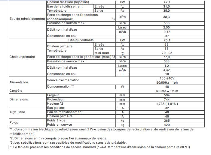
128 122

129 German 123

130 7.5.2 Solar Water Heating Collector Certificates and Data Sheets 124


131 This section includes the different SRCC certifications of the panels that were analysis during the design process. 125

132 7.5.3 PV Panel Data Sheets 126

133 127

134 7.5.4 Pump Data Sheets 128
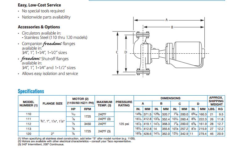
135 129
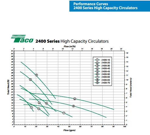
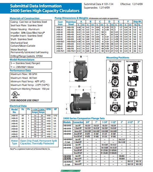
136 130
SOLAR COOLING WITH SMALL SIZE CHILLER: STATE OF THE ART
 SOLAR COOLING WITH SMALL SIZE CHILLER: STATE OF THE ART F. Asdrubali, G. Baldinelli, A. Presciutti University of Perugia (Italy) - Industrial Engineering Department 14 th European Conference - Renewable
EFFICIENT SOLAR COOLING
 EFFICIENT SOLAR COOLING Heather Poiry Kevin Balkoski Lun Jiang Roland Winston University of California, Merced 4200 N.Lake Rd, Merced CA 95348 heatherpoiry@gmail.com kbalkoski@gmail.com ljiang2@ucmerced.edu
Introduction to Geothermal Comfort Systems in INDIA
 Introduction to Geothermal Comfort Systems in INDIA History Ancient earth sheltered homes 1912 Swiss Patent 1945 - First GSHP operating in North America in Indianapolis 1949 Canada s first GSHP installation
Experimental Research and Performance Analysis of a Solar-Powered. Air-conditioning System in a Green Building
 Experimental Research and Performance Analysis of a Solar-Powered Air-conditioning System in a Green Building Xiaoqiang Zhai Ruzhu Wang Yanjun Dai Jingyi Wu Lecture Professor Professor Professor Institute
Comfort Cooling Application Using Fixed Focus Solar Parabolic Dish Concentrator Integrated with Double Effect Vapor Absorption Machine
 Comfort Cooling Application Using Fixed Focus Solar Parabolic Dish Concentrator Integrated with Double Effect Vapor Absorption Machine Anagha Pathak 1*, Kiran Deshpande 1, Niranjan Kurhe 1, Pravin Baste
THERMAL ENERGY ANALYSIS OF SOLAR POWERED VAPOUR ABSORPTION COOLING SYSTEM
 International Journal of Mechanical Engineering (IJME) ISSN(P): 2319-2240 ; ISSN(E): 2319-2259 Vol. 5, Issue 1, Dec-Jan 2016, 131-142 IASET THERMAL ENERGY ANALYSIS OF SOLAR POWERED VAPOUR ABSORPTION COOLING
Welcome Everyone. Not Quite this kind! Geothermal Heat Pumps are a indirect solar heating system! Introduction to Geothermal
 Welcome Everyone To the Introduction to Geothermal Heat Pump Technology! Introduction to Geothermal What is geothermal technology and how does it work Technology & Components Heat Pump Operation Earth
The Path Towards Zero Energy District Cooling Plant in Qatar. Salah Nezar, LEED AP, QSAS GCP, Sustainability Director, QPM
 The Path Towards Zero Energy District Cooling Plant in Qatar Salah Nezar, LEED AP, QSAS GCP, Sustainability Director, QPM Disclaimer: this is an unscientific presentation, with scientific overtones Table
Introduction to Geothermal Comfort Systems in INDIA
 Introduction to Geothermal Comfort Systems in INDIA History Ancient earth sheltered homes 1912 Swiss Patent 1945 -First GSHP operating in North America in Indianapolis 1949 Canada s s first GSHP installation
AR No. # - Solar Thermal
 AR No. # - Solar Thermal Recommendation We recommend installing a solar thermal array on the building roof. This will provide an alternative source for 10% of the facilities energy consumption and reduce
Although electricity is efficient at heating water it is expensive and not available everywhere.
 SOLAR WATER HEATING Introduction Hot water is required for many purposes and the sun can be used effectively, efficiently and economically to provide this heat. The warming effect of solar radiation is
SOLAR COOLING: STATE OF THE ART, TECHNICAL ANALYSIS AND FIRSTS APPLICATIONS
 SOLAR COOLING: STATE OF THE ART, TECHNICAL ANALYSIS AND FIRSTS APPLICATIONS F. Asdrubali, G. Baldinelli, A. Presciutti, M. Caporali University of Perugia - Industrial Engineering Department, Via G. Duranti
Mechanical Redesign. Existing System: The following schematic was devised below.
 Mechanical Redesign Existing System: The mechanical system explained in the existing conditions was simulated on an energy modeling system call equest. This program was used because of its strong detailed
Parametric Study of a Double Effect Absorption Refrigeration System
 Parametric Study of a Double Effect Absorption Refrigeration System 1 Abbas Alpaslan KOCER, 2 Murat OZTURK 1 Uluborlu Selahattin Karasoy Vocational School, Suleyman Demirel University, 32260, Isparta Turkey,
Energy Mix Opportunity of Vapor Absorption Refrigeration System Integrated With Solar Collectors: A Case Study of Hotel Shangri-La
 Proceedings of IOE Graduate Conference, 2016 pp. 349 354 Energy Mix Opportunity of Vapor Absorption Refrigeration System Integrated With Solar Collectors: Prashant Raj Neupane 1, Laxman Poudel 1 1 Department
DEVELOPMENT OF A HYBRID AIR-CONDITIONING SYSTEM DRIVEN BY LOW TEMPERATURE WASTE HEAT
 DEVELOPMENT OF A HYBRID AIR-CONDITIONING SYSTEM DRIVEN BY LOW TEMPERATURE WASTE HEAT Hirofumi Sasaki, Hiroyuki Tsuda, Technology Development Dept., Tokyo Gas Co., Ltd., Tokyo, Japan ABSTRACT Waste water
The surface receives about 47% of the total solar energy that reaches the Earth. Only this amount is usable.
 Solar Energy: The Ultimate Renewable Resource Bhavik Shah What is Solar Energy? Originates with the thermonuclear fusion reactions occurring in the sun. Represents the entire electromagnetic radiation
SOLAR ENGINEERING OF THERMAL PROCESSES
 SOLAR ENGINEERING OF THERMAL PROCESSES Second Edition JOHN A. DUFFIE Emeritus Professor of Chemical Engineering WILLIAM A. BECKMAN Professor of Mechanical Engineering Solar Energy Laboratory University
Performance analysis of a new single effect hot water absorption chiller system
 University of Technology, Sydney Master Thesis Performance analysis of a new single effect hot water absorption chiller system Author: Saket Sinha Supervisor: Associate Professor Quang Ha A thesis submitted
Figure 1: Uncovered and covered PVT collectors
 Low energy cooling of buildings with radiative cooling using hybrid PVT collectors Ursula Eicker, Antoine Dalibard, Simon Büttgenbach, Sebastian Fiedler, Jan Cremers University of Applied Sciences HFT
Optimisation and Cost Analysis of a Lithium Bromide Absorption Solar Cooling System
 Optimisation and Cost Analysis of a Lithium Bromide Absorption Solar Cooling System Georgios A. Florides and Soteris A. Kalogirou Mechanical Engineering Department, Higher Technical Institute, Nicosia,
Basics of Solar Photovoltaics. Photovoltaics (PV) Lecture-21
 Lecture-21") Lecture-21 Basics of Solar Photovoltaics Photovoltaics (PV) Photovoltaics (PV) comprise the technology to convert sunlight directly into electricity. The term photo means light and voltaic, electricity.
Lecture-21 Basics of Solar Photovoltaics Photovoltaics (PV) Photovoltaics (PV) comprise the technology to convert sunlight directly into electricity. The term photo means light and voltaic, electricity.
Level 1 Modules tdp-101 hvac industry overview tdp-103 concepts of air conditioning tdp-102 abcs of comfort
 TDP-101 HVAC Industry Overview This TDP provides a general overview of the commercial HVAC industry and provides an awareness of the design process and construction. The documents involved in construction,
REPORT ON THE BENEFITS OF ICE- BASED THERMAL STORAGE FOR DISTRICT COOLING IN THE UAE MARKETS
 REPORT ON THE BENEFITS OF ICE- BASED THERMAL STORAGE FOR DISTRICT COOLING IN THE UAE MARKETS Prepared by: Brady Consulting Services, Inc. SUMMARY ADVANTAGES OF THERMAL STORAGE WITH 1.1ºC WATER SUPPLY 1)
TDPs provide you with new technical training materials designed to help your contractors, engineers, and designers to effectively design, specify,
 TDP Catalog TDPs provide you with new technical training materials designed to help your contractors, engineers, and designers to effectively design, specify, sell, and apply HVAC equipment in commercial
Solar Powered Vapour Absorption Refrigeration (SPVAR) System as a rural microenterprise
 System as a rural microenterprise") Solar Powered Vapour Absorption Refrigeration (SPVAR) System as a rural microenterprise Anurag Mudgal, Pandit Deendayal Petroleum University, India Jatin Kumar Patel, Pandit Deendayal Petroleum University,
Solar Powered Vapour Absorption Refrigeration (SPVAR) System as a rural microenterprise Anurag Mudgal, Pandit Deendayal Petroleum University, India Jatin Kumar Patel, Pandit Deendayal Petroleum University,
use Solar thermal for hot water production
 use Solar thermal for hot water production DESIGN STRATEGIES sustainable HOT WATER SOLUTIONS SOLAR HOT WATER Production of domestic hot water by converting direct sunlight into thermal energy through use
Wentworth Institute of Technology
 Wentworth Institute of Technology Electronics and Mechanical Department MECH620-03-04 Thermal Design A Proposal to Design and Implement Green Technology into Greenhouse Operations Submitted to Professor
use Solar thermal for hot water production DESIGN APPROACHES
 use Solar thermal for hot water production DESIGN APPROACHES GLUMAC DESIGN APPROACHES sustainable HOT WATER SOLUTIONS S SOLAR HOT WATER Production of domestic hot water by converting direct sunlight into
Performance Analysis of a Solar Powered Adsorption Cooling System
 Paper ID: ET-263 Performance Analysis of a Solar Powered Adsorption Cooling System Sai Yagnamurthy 1 Dibakar Rakshit *1 Sanjeev Jain 2 1 Centre for Energy Studies, Indian Institute of Technology, Delhi-110016,
GEOTHERMAL SPACE COOLING
 GEOTHERMAL SPACE COOLING 6th African Rift Geothermal Conference ARGeo-C6 Short Course 1 Project Management for Geothermal Development Þorleikur Jóhannesson (Presenter: Yngvi Guðmundsson) Compressor driven
FLATE Hillsborough Community College - Brandon (813)
") The Florida Advanced Technological Education (FLATE) Center wishes to make available, for educational and noncommercial purposes only, materials relevant to the EST1830 Introduction to Alternative/Renewable
The Florida Advanced Technological Education (FLATE) Center wishes to make available, for educational and noncommercial purposes only, materials relevant to the EST1830 Introduction to Alternative/Renewable
Draft proposals for Test methods for close-coupled solar water heating systems - Reliability and safety
 IEA/SHC Task 57, Subtask B Draft proposals for new test procedures B4: Final Draft Draft proposals for Test methods for close-coupled solar water heating systems - Reliability and safety HE Zinian Beijing
The Potential and Challenges of Solar Boosted Heat Pumps for Domestic Hot Water Heating
 The Potential and Challenges of Solar Boosted Heat Pumps for Domestic Hot Water Heating Stephen Harrison Ph.D., P. Eng., Solar Calorimetry, Dept. of Mechanical and Materials Engineering, Queen s University,
A new application of an old idea
 Thermal Energy Storage A new application of an old idea As the second-most populated country on this planet, India s ever-growing demand for energy has shown no signs of dwindling. A clearly strained electricity
CMR Journal of Engineering and Technology Vol.2 Issue.2 April, 2018
 Desalination using Concentrated solar thermal plants with thermal energy storage systems 1.0 Introduction Pavan Kumar Bhagavathula PG Student, Rhine-Waal University of Applied Sciences Kleve, Germany Desalination
Development of an Innovative 2.5 kw Water- Silica Gel Adsorption Chiller
 Development of an Innovative 2.5 kw Water- Silica Gel Adsorption Chiller E.-J. Bakker R. de Boer S. Smeding N. Sijpheer M. van der Pal September 2013 ECN-B--13-011 DEVELOPMENT OF AN INNOVATIVE 2.5 kw WATER-SILICA
BUILDING FOR THE FUTURE
 BUILDING FOR THE FUTURE The following article was published in ASHRAE Journal, September 4. Copyright 4 American Society of Heating, Refrigerating and Air- Conditioning Engineers, Inc. It is presented
Digging Deeper SOLAR ENERGY. Forms of Solar Energy
 a) Is the wind speed the same in the morning; the afternoon; the evening? b) Move your anemometer to another location. Is it windier in other places? c) Do trees or buildings block the wind? 7. Back in
Energy System Terminology
 Air Handling Unit (AHU) A central unit consisting of a blower, heating and cooling elements, filter racks or chamber, dampers, humidifier, and other central equipment in direct contact with the airflow.
SOLAR PHOTOVOLTAICS Part 1
 SOLAR PHOTOVOLTAICS Part 1 Solar Energy Contents Irradiance, Solar Constant Solar Window & tilt effects Atmospheric effects, air mass Solar spectrum, sensitivity of PV materials to various wavelengths
Solar Heating in Commercial Buildings
 Washington University in St. Louis Washington University Open Scholarship Mechanical Engineering and Materials Science Independent Study Mechanical Engineering & Materials Science 12-19-2017 Solar Heating
Second Law of Thermodynamics
 Second Law of Thermodynamics Content Heat engine and its efficiency. Reversible and irreversible processes. The Carnot machine. Kelvin Planck Statement. Refrigerator and Coefficient of Performance. Statement
BY HARNESSING THE POWER OF THE SUN WE ARE ABLE TO PRODUCE HOT WATER AND ELECTRICITY FROM AN INEXHAUSTIBLE SOURCE WITHOUT ADDING TO THE CARBON LEVELS
 SOLAR BY HARNESSING THE POWER OF THE SUN WE ARE ABLE TO PRODUCE HOT WATER AND ELECTRICITY FROM AN INEXHAUSTIBLE SOURCE WITHOUT ADDING TO THE CARBON LEVELS IN THE ATMOSPHERE. SOLAR PANELS (PV) A typical
Experimental investigation of solar-driven double ejector refrigeration system
 Experimental investigation of solar-driven double ejector refrigeration system Jedsada Visedmanee a *, Anan Pongtornkulpanich a, Sakda Somkun a and Ananchai U-kaew b a Thermal Energy Research Unit, School
AR No. # Solar Thermal. Assessment Recommendation Savings Summary Source. Cost Savings Natural Gas. $984 * 1 MMBtu = 1,000,000 Btu
 AR No. # Solar Thermal Recommendation We recommend installing a solar thermal array on the building roof. This will provide an alternative source for 9.8% of the facilities energy consumption and reduce
Packaged Refrigerant Based Energy Storage (RBES) Air Conditioning System
 Air Conditioning System") Packaged Refrigerant Based Energy Storage (RBES) Air Conditioning System Ram Narayanamurthy Ice Energy, Inc. this technology provides some of the largest opportunities we have right now to address the
Packaged Refrigerant Based Energy Storage (RBES) Air Conditioning System Ram Narayanamurthy Ice Energy, Inc. this technology provides some of the largest opportunities we have right now to address the
Solar cooling plants: how to arrange solar collectors, absorption chillers and the load
 Solar cooling plants: how to arrange solar collectors, absorption chillers and the load Renato M. Lazzarin Dipartimento di Tecnica e Gestione dei Sistemi industriali, DTG Università di Padova (Italy) E-mail:
REPORT DOCUMENTATION PAGE
 REPORT DOCUMENTATION PAGE Form Approved OMBNo.0704-018 Public reporting burden for this collection of information is estimated to average 1 hour per response, including the time for reviewing instructions,
Session 6. Solar Power Plant
 Session 6 Solar Power Plant What is Solar Energy? Originates with the thermonuclear fusion reactions occurring in the sun. Represents the entire electromagnetic radiation (visible light, infrared, ultraviolet,
Section 5. Renewable Energy Sources Solar and Wind. What Do You See? Think About It. Investigate. Learning Outcomes
 Chapter 7 Earth s Natural Resources Section 5 Renewable Energy Sources Solar and Wind What Do You See? Learning Outcomes In this section, you will Construct a solar water heater and determine its maximum
Investigating Two Configurations of a Heat Exchanger in an Indirect Heating Integrated Collector Storage Solar Water Heating System
 Journal of Energy and Power Engineering 7 (2013) 66-73 D DAVID PUBLISHING Investigating Two Configurations of a Heat Exchanger in an Indirect Heating Integrated Collector Storage Solar Water Heating System
Technical Guide to Solar Thermal. Better World Energy. How to harness the sun s energy and create hot water with a Solar Thermal System
 Technical Guide to Solar Thermal Better World Energy How to harness the sun s energy and create hot water with a Solar Thermal System Introducing Ritter XL Solar Ritter XL Solar Thermal Systems have been
Guide. Heat Pump Boilers. Information. Issue Ten >
 Information Guide Heat Pump Boilers Issue Ten > Heat Pump Boilers Information Guide This is an independent guide produced by Mitsubishi Electric to enhance the knowledge of its customers and provide a
The Potential and Challenges of Solar Boosted Heat Pumps for Domestic Hot Water Heating
 The Potential and Challenges of Solar Boosted Heat Pumps for Domestic Hot Water Heating Stephen Harrison Ph.D., P. Eng., Solar Calorimetry, Dept. of Mechanical and Materials Engineering, Queen s University,
Reducing The Carbon Output Of A Modern Commercial Building
 Reducing The Carbon Output Of A Modern Commercial Building CSA Grade 5 Thesis By Gary James January 2008 Page 1 of 10 Reducing The Carbon Output Of A Modern Commercial Building Introduction The burning
Solar Air-Conditioning Systems in small - medium scale applications
 Systems in small - medium scale applications Santzaklis Ioannis MSc Mechanical engineering MBA Techno-economic systems Centre for Renewable Energy Sources Dissemination and Promotion dept. Christodoulaki
UNIT FOUR SOLAR COLLECTORS
 ME 476 Solar Energy UNIT FOUR SOLAR COLLECTORS Concentrating Collectors Concentrating Collectors 2 For many applications it is desirable to deliver energy at temperatures higher than those possible with
Utilities Infrastructure Cooling Production. Purpose of Today s Presentation. Agenda. GLHN Architects & Engineers, Inc. APPA Institute Session 301C EU
 Utilities Infrastructure Cooling Production APPA Institute for Facilities Management Dallas Jan 2017 Bill Nelson PE 1 Purpose of Today s Presentation To provide a broad understanding of central cooling
SorTech package solution description
 SorTech package solution description Version 2.0 Edited by: Jörg Rupp Lotta Koch, Edo Wiemken, Björn Nienborg Freiburg, 06.10.2009 Table of Contents 1 Introduction... 3 2 The Chiller... 4 3 System s Components...
3 Mechanical System Redesign
 3 Mechanical System Redesign 3.1 Considered Alternatives The MAC building offered many opportunities to change the existing design and explore an alternative different than the solution the original design
Customized Absorption Heat Pumps for Utilization of Low-Grade Heat Sources
 Customized Absorption Heat Pumps for Utilization of Low-Grade Heat Sources Christian Keil, Stefan Plura, Michael Radspieler, Christian Schweigler ZAE Bayern, Bavarian Center for Applied Energy Research
Conceptual Design of Nuclear CCHP Using Absorption Cycle
 Conceptual Design of Nuclear CCHP Using Absorption Cycle International Conference on Opportunities and Challenges for Water Cooled Reactors in the 21 st Century Vienna, Austria, October 27-30, 2009 Gyunyoung
Free Cooling Technology
 Free Technology Utilise low ambient temperatures to save energy and reduce your cooling costs by up to 70% Free for industrial process and air conditioning How Free can save you money Free is a fast and
Card #1/24. Describe how thermal energy is passed on in terms of ions Using these ideas explain how a convection current occurs
 Card #1/24 Card #2/24 Topic: Conduction Topic: Convection In what state of matter does conduction occur? In what states of matter does convection occur? Explain why it needs to be in this state? Define
Thermally operated mobile air-conditioning system
 Thermally operated mobile air-conditioning system Development and test of a laboratory prototype R. de Boer S.F. Smeding Paper to be presented on the International Sorption Heat Pump Conference 2008, Seoul,
TRIGENERATION TECHNOLOGY
 FINATER FINATER OFFERS INNOVATIVE AND SUSTAINABLE SOLUTIONS TO COMPANIES AND COMMUNITIES TO HELP THEM TO : BETTER USE ENERGY OPTIMIZE ENERGY EFFICIENCY REDUCE THEIR ENVIRONMENTAL IMPACT ENERGY EFFICIENCY
Application of solar cooling system in a campus library in Hainan, China
 Available online at www.sciencedirect.com Energy Procedia 30 (2012 ) 730 737 SHC 2012 Application of solar cooling system in a campus library in Hainan, China Li Zhong a*, Nie Jingjing a, Zhang Xinyu a,
Compound ejectors with improved off-design performance
 Compound ejectors with improved off-design performance Dr M. Dennis 1, Dr K. Garzoli 2 1,2 Centre for Sustainable Energy Systems School of Engineering The Australian National University Canberra, ACT 0200
Pool Boiling Heat Transfer to Water/Lithium Bromide Mixture
 International Conference on Challenges and Opportunities in Mechanical Engineering, Industrial Engineering and Management Studies 548 Pool Boiling Heat Transfer to Water/Lithium Bromide Mixture A. Sathyabhama
Energy Saving Report. Frigi-Tech Oil Additive. Application. In HKU Central Plant. Chiller No. 3
 Energy Saving Report Of Frigi-Tech Oil Additive Application In HKU Central Plant Chiller No. 3 Prepared By: Evaluated and Endorsed By: December 2003 Eric P L Leung Sales Manager Electrical and Mechanical
Experimental investigation of photovoltaic-thermal hybrid solar collector
 Agronomy Research Biosystem Engineering Special Issue 1, 7-34, 01 Experimental investigation of photovoltaic-thermal hybrid solar collector V. Zagorska, I. Ziemelis, L. Kancevica and H. Putans Latvia University
INSIDE: ASHRAE Hall of Fame
 This article was published in ASHRAE Journal, February 2011. Copyright 2011 American Society of Heating, Refrigerating and Air-Conditioning Engineers, Inc. Reprinted here by permission from ASHRAE. This
ELG4126 Solar Energy The Ultimate Renewable Resource. Based Partially on Renewable and Efficient Electric Power System, Gilbert M.
 ELG4126 Solar Energy The Ultimate Renewable Resource Based Partially on Renewable and Efficient Electric Power System, Gilbert M. Masters, Wiely What is Solar Energy? 1.4 million kilometer diameter, thermonuclear
Advanced heat driven cooling cycles for low-temperature waste heat recovery
 CDTI-NEDO Joint Workshop on Energy Saving Engineering - Effective Use of Thermal Energy Advanced heat driven cooling cycles for low-temperature waste heat recovery 02/13/2018 Tatsuo Fujii Research & Development
Contents. Contents. Module 1 Photovoltaic panels in context of renewable technologies 1
 BPEC Domestic Solar Photovoltaic Systems Learning Manual BPEC0018 Contents Contents Page Module 1 Photovoltaic panels in context of renewable technologies 1 Module 2 How a photovoltaic system works principles
Central Chiller Plants
 Central Chiller Plants Institute for Facilities Management New Orleans, LA January 18,2016 Course 319 Presenter: John Vucci Associate Director HVAC Systems University of Maryland College Park, Maryland
A STUDY OF ABSORPTION CHILLER/HEATER APPLICATION IN MARINE ENGINEERING
 A STUDY OF ABSORPTION CHILLER/HEATER APPLICATION IN MARINE ENGINEERING The 4 th Biennial Marine Transportation System (MTS) Research & Development Conference, June 21-23, 2016 Advantages of Applying Absorption
ACTIVE SOLAR SYSTEMS
 ACTIVE SOLAR SYSTEMS ENGS 44 Sustainable Design Benoit Cushman-Roisin 17 April 2017 There are situations where one may wish to go beyond passive solar gain. Some of the reasons are: There is not enough
Energy Assessment Report Clayville Elementary School DRAFT October George Washington Highway, Clayville, RI DRAFT
 Report Clayville Elementary School October 2016 3 George Washington Highway, Clayville, RI 02815 Clayville Elementary School Summary of Findings On behalf of the School Building Authority at Rhode Island
The Present and Future of Refrigeration, Power Generation and Energy Storage. R.Z. Wang Shanghai Jiao Tong University
 The Present and Future of Refrigeration, Power Generation and Energy Storage R.Z. Wang Shanghai Jiao Tong University Contents Introduction Refrigeration Power generation Energy storage Discussions Introduction
Optimization of Solar Cooling Systems with Simulation Modeling
 Journal of mathematics and computer Science 6 (2013) 286-291 Optimization of Solar Cooling Systems with Simulation Modeling Hamid Reza Feili 1,*, Fatemeh Moghadasi 2, Parisa Naderipour 3, 1 Faculty of
Myth Busters Absorption Cooling Technology. Rajesh Dixit
 Myth Busters Absorption Cooling Technology Rajesh Dixit 1 Acknowledgements Hitachi-Johnson Controls A/C Japan Shuichiro Uchida Takashi Nishiyama Shigehiro Doi 2 Learning Objectives Busting Myths About
Large University Central Chiller Plant Design Considerations
 Carrier Engineering Newsletter Volume 5, Issue 3 Large University Central Chiller Plant Design Considerations Large campus chilled water plants have unique constraints and need careful evaluation for successful
Ener.co & Viridian Energy & Env. Using Data Loggers to Improve Chilled Water Plant Efficiency. Randy Mead, C.E.M, CMVP
 Ener.co & Viridian Energy & Env. Using Data Loggers to Improve Chilled Water Plant Efficiency Randy Mead, C.E.M, CMVP Introduction Chilled water plant efficiency refers to the total electrical energy it
December 13, 2012 Energy Efficient Cooling Information Service Webinar Series Christine Brinker and Gearoid Foley CHP with Absorption Chilling
 December 13, 2012 Energy Efficient Cooling Information Service Webinar Series Christine Brinker and Gearoid Foley CHP with Absorption Chilling Technical Assistance Education and Outreach Executive Order
Simulation Studies on Performance of Solar Cooling System in UAE Conditions
 Available online at www.sciencedirect.com Energy Procedia 00 (2014) 000 000 www.elsevier.com/locate/procedia SHC 2013, International Conference on Solar Heating and Cooling for Buildings and Industry September
SunMaxxTM Information Guide: Evacuated Tube Solar Collectors
 SunMaxxTM Information Guide: Evacuated Tube Solar Collectors P: 877.SUNMAXX / 888.SOLAR.11 www.siliconsolar.com / www.sunmaxxsolar.com Silicon Solar Inc Innovative Solar Solutions SunMaxxTM Information
Technical Development Program
 TDP Catalog TDPs provide you with new technical training materials designed to help your contractors, engineers, and designers to effectively design, specify, sell, and apply HVAC equipment in commercial
THE SECOND LAW OF THERMODYNAMICS
 Fundamentals of Thermal-Fluid Sciences, 3rd Edition Yunus A. Cengel, Robert H. Turner, John M. Cimbala McGraw-Hill, 2008 THE SECOND LAW OF THERMODYNAMICS Mehmet Kanoglu Copyright The McGraw-Hill Companies,
Mechanical Project Proposal
 Mechanical Project Proposal Miller Children s Hospital Prepared for: Dr. James Freihaut Department of Architectural Engineering The Pennsylvania State University Prepared by: Stephen Haines December 18
Rooftops High performance, proven reliability and easy installation
 Rooftops High performance, proven reliability and easy installation 1 Airfinity Rooftops Comfort and economy When it comes to installing and maintaining an HVAC system, every cent counts. From your initial
NTT DOCOMO Technical Journal. Design and Evaluation of Thermal-photovoltaic Hybrid Power Generation Module for More Efficient Use of Solar Energy
 Photovoltaic Power Generation Light Concentration Technology Combined Heat and Power Design and Evaluation of Thermal-photovoltaic Hybrid Power Generation Module for More Efficient Use of Solar Energy
What is District Energy
 A Special Review of District Energy & Integrated Distributed Energy presented to prepared by October 2010 SECTION ONE What is District Energy Technology? What is District Energy Technology? District Energy
ECE 4901 Design I Fall Solar Panel & Solar Thermal Heating Project (UConn Spring Valley Farm) Project Proposal
 Project Proposal") ECE 4901 Design I Fall 2014 Solar Panel & Solar Thermal Heating Project (UConn Spring Valley Farm) Project Proposal Faheem Dalal (EE), Jorge Llivichuzhca (EE), Stephanie Mesick (EE) Faculty advisor: Dr.
ECE 4901 Design I Fall 2014 Solar Panel & Solar Thermal Heating Project (UConn Spring Valley Farm) Project Proposal Faheem Dalal (EE), Jorge Llivichuzhca (EE), Stephanie Mesick (EE) Faculty advisor: Dr.
Energy Efficient Solar Milk Chiller
 Energy Efficient Solar Milk Chiller Muneeb Bin Muzzamal Abstract: Life stock is the major sector of agriculture which is of great importance for Pakistan. It has a major contribution towards the economy
Innovative Systems for Solar Air Conditioning of Buildings
 Innovative Systems for Solar Air Conditioning of Buildings Dr. Wolfgang KESSLING Project Manager Transsolar Energietechnik GmbH Goethestrasse 8, 80336 Munich, Germany kessling@transsolar.com Dipl.-Ing.
EXERGY LOSS ANALYSIS OF THE REGENERATOR IN A SOLAR STIRLING ENGINE
 S729 EXERGY LOSS ANALYSIS OF THE REGENERATOR IN A SOLAR STIRLING ENGINE by Wenlian YE a, b, Zhe YANG a, and Yingwen LIU a* a Key Laboratory of Thermo-Fluid Science and Engineering of MOE, School of Energy
Combined Heat and Power
 Lecture 12 Combined Heat and Power Combustion Turbines and Co-generation Combustion Turbines and Combined Heat and Power (CHP) Systems See B. K. Hodge, Chapter 5 and Chapter 11. ISBN: 978-0-470-14250-9
Gas Turbine Inlet Air Cooling System
 Gas Turbine Inlet Air Cooling System Presented by Bob Omidvar Heavy Duty GT - Effects of Ambient Temp 110% 105% 100% 95% 90% 85% 80% 75% 0 5 10 15 20 25 30 35 40 45 GT Inlet Temp (deg C) Heat rate kj/kwh