New Developments in BioWin 5.3
|
|
|
- Lauren Kelly
- 6 years ago
- Views:
Transcription

 element is available to represent this process in BioWin configurations.")


1 New Developments in BioWin 5.3 December 6, 2017 BioWin 5.3 contains a new Granular Sludge Sequencing Tank element to model this process, which is gaining acceptance worldwide as an effective wastewater treatment technology. BioWin 5.3 also contains an enhancement to the trickling filter element and refinements to model parameters. Granular Sludge Sequencing Tank A Granular Sludge Sequencing Tank (GSST) element is available to represent this process in BioWin configurations. The modeling approach uses BioWin s one-dimensional dynamic biofilm model to mimic the granular sludge. A one-dimensional layered solids flux model is applied for modeling settling of nongranular flocculent mixed liquor solids during unaerated/unmixed periods. These models are integrated with the general ASDM in a variable volume unit that allows various phases of operation to be specified. The GSST model has been developed to balance pragmatic design elements with mechanistic modeling rigor, to provide quick solution times, and typical process performance predictions. Most GSST technology implementations employ a repeated batch-fed process. The microorganisms responsible for the majority of the carbon, nitrogen and phosphorous removal grow in dense granules rather than conventional activated sludge flocs. These granules settle rapidly, eliminating the need for separate settling tanks. The granules have a layered structure that may be more aerobic on the outside and anoxic or anaerobic towards the centre. This structure allows the granular sludge to simultaneously remove carbon, nitrogen and phosphorous from the wastewater in a single reactor/settler. Further details on the GSST element are provided in Appendix A. 1
2 Element Enhancement Trickling Filter Hydraulic loading may impact the area available for gas transfer. If the wetting rate is too low then not all of the media will be wet so the gas transfer area will be reduced. On the other hand, if the hydraulic loading rate gets too high then it is possible that the air spaces between the media become filled with liquid, which also will reduce the available gas transfer area. The Hydraulic Loading Factor attempts to account for these less-than-optimal conditions. The Hydraulic Loading Factor is determined by a two-sided continuous switching function. Over an optimal range of hydraulic loading the Hydraulic Loading Factor is equal to or close to unity (1). The value decreases towards zero for extreme low or high loading rates. The form of the continuous switching function is defined by the Low hydraulic loading rate switch value and the High hydraulic loading rate switch value. These are the low and high hydraulic loading rates where the Hydraulic Loading Factor has a value of 0.5 (i.e. the area for gas transfer is reduced to half of the effective area). Different media types have characteristic high and low loading rates. In BioWin 5.3 we improved the continuous switching function of the hydraulic loading factor so that the trickling filter more accurately calculates the available area for gas transfer at extreme low or high loading rates. Our extensive testing has shown that the improved continuous switching function brings the predicted nitrification performance in line with measured data for numerous full-scale trickling filters under extreme low or high loading rates. The hydraulic loading factor plots for rock media and non-rock media/other media types are shown below: HYDRAULIC LOADING FACTOR AS A FUNCTION OF HYDRAULIC LOADING FOR ROCK MEDIA 2
3 HYDRAULIC LOADING FACTOR AS A FUNCTION OF HYDRAULIC LOADING FOR NON-ROCK/OTHER MEDIA TYPES Default Parameter Changes Biofilm Attachment / Detachment Rates Particulate attachment and detachment rates have a major role in establishing biofilm thickness, dynamics, and system activity, similar to SRT in activated sludge. The biofilm model is employed in the media bioreactors, trickling filters, submerged aerated filters and granular sludge sequencing tank in BioWin. EnviroSim performed numerous model calibrations of these types of systems to measured BOD, ammonia, NO X and biofilm growth profiles from full-scale and pilot-scale plants. Through this extensive testing, we have revised the default biofilm attachment and detachment rates to 8 g/(m 2 d) and 8,000 g/(m 3 d), respectively. [The former respective attachment and detachment rates were 80 g/(m 2 d) and 80,000 g/(m 3 d), respectively]. OHO Dissolved Oxygen Half Saturation Coefficient The ordinary heterotroph organism (OHO) dissolved oxygen (DO) half-saturation coefficient (K DO ) is used in several OHO rate expressions (e.g. growth, decay) to switch off aerobic OHO activity under low DO conditions, and turn on anoxic processes in the presence of NO X. In previous versions of BioWin, the default value for this parameter was 0.05 mg O 2 /L. This meant that anoxic processes only would be turned on in the model under very low DO conditions, and BioWin was conservative in nitrogen removal predictions by default. This value was selected based on observations of laboratory and pilot-scale systems that typically had shallow liquid depths (relative to full-scale systems), vigorous mixing and/or high air flow rates all of which combined to yield small sludge flocs and very little evidence of denitrification even at relatively low DO levels. 3

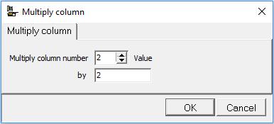
4 However, in full-scale systems, lower levels of mixing intensity as well as other non-idealities often result in some degree of denitrification occurring at low DO levels. To reflect this with its default parameter set, in BioWin 5.3 the default OHO K DO has been increased from 0.05 mgo 2 /L to 0.15 mgo 2 /L. Obviously, the user can adjust this parameter to best fit observed process behavior, however, BioWin 5.3 will be somewhat less conservative in its predictions than previous versions for nitrogen removal if there are low DO zones incorporated in the process flowsheet. Further details on all new features in BioWin 5.3 can be found in the Help manual. Usability Feature Multiply a Column by a Factor Users may now multiply a column of values by a factor. This is done by right clicking on the Value column and selecting Multiply column from the pop-up window. In the example below, the initial state variable concentrations in a variable volume bioreactor are multiplied by a factor of 2 to increase the starting concentrations in the mixed liquor. 4
5 5
6 Appendix A - Granular Sludge Sequencing Tank Model Description In the modeling approach, the granular sludge mass is represented by a biofilm with a calculated surface area and film thickness. The biofilm thickness is assumed to be equivalent to the average granule radius. The model does not predict new granule formation or consider a granule size distribution, but the diameter of granules may change dynamically depending on loading. The dynamic mixed-culture biofilm model used in the approach includes the following aspects: A boundary layer at the biofilm surface as a diffusion resistance for mass transfer of solutes. Diffusion of soluble, particulate and dissolved gaseous components within the biofilm. Exchange of particulates between the film surface and the bulk liquid due to detachment (erosion) and attachment (impingement). Growth (and decay) of different biomass species within the biofilm. In general, the GSST flowsheet element in which the models are implemented incorporates the following features to capture typical operational aspects of GSSTs and the resulting process performance: Each cycle in the GSST has a mixing phase followed by a settling phase. Aeration may be switched on and off during the mixing phase (based on DO setpoint or air flowrate). During the mixing phase, the granules are assumed to be completely mixed within the bulk liquid. When settling begins, the granules instantaneously settle to the bottom of the tank and occupy a percentage of the reactor volume. The volume of the granules themselves is based on granular biofilm volume. However, the volume occupied by the granules is larger because volume is reserved for voidage between the granules. The GSST uses a variable volume one-dimensional solids flux model to simulate settling of mixed liquor (non-granular) solids. The bulk liquid above the volume of settled granules is divided into n equal-depth layers during settling (n = 10 in the default GSST implementation). The GSST typically is fed at or near the end of the settling phase. The feed enters the bottom of the tank where the settled granules are located and flows through the voidage volume across the surface of the settled granules. The voidage volume is considered to be completely mixed, rather than plug or semi-plug flow. As the feed flows into the bottom of the unit, liquid is displaced upward, through the layers above the granule volume. At the top of the GSST, liquid can overflow or be decanted as treated effluent. Waste activated sludge (WAS) is removed from the bottom layer of the settled mixed liquor solids; the granules are not removed in the waste flow. However, granular mass and composition is not static because there is attachment to and detachment from the granule surface continuously during the mixed phase. The user has the option to incorporate a small decant event prior to commencing a mix/react phase to drop the liquid level in the GSST. This provides some freeboard to avoid spillage of mixed reactor contents when aeration commences. The decant is removed from the top layer of the bulk liquid. 6
7 Flow schematic of the GSST in settle mode The BioWin user working with wastewater treatment plants employing GSST technology will be able to obtain answers for the following questions: How much granular sludge mass and granular sludge surface area is required to achieve a specific process objective? How much active biomass will the granular sludge contain? What will the average diameter of the granules be (in mm) depending on substrate loading, solids exchange between the granules and the bulk liquid, EPS strength coefficients and the effect of gas (N 2, CH 4, CO 2 ) generation inside the granules? How will soluble and particulate components be distributed inside the granules? Will different growth regimes (e.g. aerobic, anoxic, anaerobic) exist over the granule radius? How will the reaction rates for the biological processes (growth and decay of heterotrophic and autotrophic biomass, fermentation, etc.) be distributed within the granules? Will ph effects and precipitation reactions within the granules significantly change porosity, density and conversion rates? 7
8 GSST parameters This section describes the rationale behind some of the default settings that exist within the GSST element when it is first placed on the drawing board. It is important to note that these are not intended to serve as strict design guidelines, but rather, reasonable starting points. Dimensions tab The GSST usually is 16 to 24 feet (4.9 to 7.3 m) deep. When the GSST element is placed onto the drawing board, the default depth is 6 m. Granules tab The formation of the granules is not modelled; the GSST initially contains a user-input estimated volume of granular sludge. The user also specifies estimates for the initial granule diameter (D) and a voidage factor (e) for settled granules, as follows: Estimated granule diameter (D) [mm]. This sets the initial diameter of the granules at the beginning of a simulation from seed conditions. The actual diameter is a simulated output and will change from the initial estimate over the duration of a simulation. Estimated granule settled volume fraction (FG) of reactor volume (Vt). This sets the initial estimate of the reactor volume occupied by both the granules and the intergranular voidage when granules are settled on the bottom of the reactor at the beginning of a simulation from seed conditions. The actual settled volume is a simulated output and will change from the original estimate over the duration of a simulation. Voidage (of settled granules) (E). This sets the percentage of the granule settled volume occupied by voidage. Although the granule diameter and settled volume parameters are simulated and may change over the course of a simulation, the voidage percent is assumed to remain constant over the duration of a simulation. 8

9 The granules tab of a GSST These user-defined parameters are used to calculate the base granular surface area. The base granular surface area and the user-specified voidage fraction are held constant throughout a dynamic simulation. The GSST model dynamically calculates the granular diameter depending on a number of factors, such as substrate loading and solids exchange between the granules and the bulk liquid. The granular settled volume fraction of the reactor volume changes proportionally to the model-calculated granular surface area. Operation tab The major operational settings of the GSST are the cycle settings. The Operation tab of the GSST is shown below. Note the cycle length, settling and decant periods correspond to the default settings observed when you drop a GSST element onto the drawing board. 9

10 The figure below is an alternative illustration of the operational cycle of the GSST element when it is dropped onto the drawing board. The user may specify the aeration settings in the GSST using a DO set-point or air flow rate at a constant value or following a defined pattern. The react/mix phase in the GSST element sets the maximum time span for aeration. Waste tab Typically thickened mixed liquor is removed from the GSST partway into the settling period, before the GSST is fed. Granules are never wasted from the GSST, only bulk mixed liquor. If wasting occurs at some point in the settling period, it is removed from the bottom settling layer. Initial values tab The user may set up the initial settings of the bulk mixed liquor concentrations and liquid hold-up in the GSST element. 10

11 Power options The user may enter power specifications for mechanical mixing in the GSST. Power can be specified on a power per unit volume basis or on a fixed basis at a constant value or in a pattern. Model tab When a GSST element is placed onto the drawing board, local biofilm, kinetic, diffuser and settling parameters are applied, as shown below. This is done to allow certain parameter values in the GSST to differ from BioWin s global defaults. The reasoning for adjusting these particular parameter values is described below. The user may adjust any of the model parameter values to calibrate a GSST model to measured data. The default settings are provided as a means to achieve typical process performance, but are not intended to serve as strict design guidelines. Under the Granule model options section on the Model tab, the number of internal layers (through granule) setting is specified as three. Increasing the number of layers may impact gradients of dissolved oxygen, substrates and biomass species throughout the granules. However, the biofilm model is computationally intensive, so increasing the number of layers increases simulation time. Assuming three layers appears to provide a good balance of these factors in calibrating GSST models to full-scale and pilot-scale systems. The Boundary layer thickness is specified as 50 micrometers. This thickness appears suitable for calibrating GSST models with respect to the observed removal of nitrogen and phosphorous. 11
12 Local biofilm parameters are used to specify thin and thick biofilm limits lower than the BioWin defaults, and maximum biofilm concentrations of particulate organics greater than the BioWin defaults. o The granular sludge mass is represented by a biofilm with a calculated surface area and film thickness. The biofilm thickness is assumed to be equivalent to the average granule radius. The granular diameter is therefore equivalent to two times the biofilm thickness. When the GSST element is placed onto the drawing board, the thin and thick film limits are set at 0.3 mm and 0.75 mm, respectively. This favors the development of granular diameters between 0.6 mm and 1.5 mm. o The concentration of organic particulate state variables may be higher in granules than in conventional biofilms growing in IFAS and MBBR systems. The user may easily increase the maximum biofilm concentrations of particulate organics by right-clicking on the value column, selecting Multiply column (Part. organics only), and then specifying a factor. When the GSST element is placed onto the drawing board, the specified maximum biofilm concentrations of particulate organics are 5 times the default values. Local kinetic parameters are used to set the OHO dissolved oxygen half saturation parameter on the Switches tab to 0.25 mgo 2 /L. This allows for more simultaneous nitrification/denitrification than is typically observed in well-mixed well-aerated conventional activated sludge reactors. The user may adjust this parameter to calibrate the GSST model to match measured effluent ammonia, nitrate and nitrite concentrations. Local diffuser parameters are used to modify the K1 parameter. The K1 parameter value has been decreased to 1.0 to achieve reasonable SOTE performance at a GSST depth of 6 m. Local settling parameters are set to adjust the maximum Vesilind settling velocity (Vo), Vesilind hindered zone settling parameter (K) and Maximum compactability constant parameter values to reflect the rapid settling observed in GSSTs. The Vo value is 340 m/d and the K value is 0.18 L/g. To avoid losing a significant mass of bulk suspended solids, the settling velocity of the interface must be greater than the upflow velocity when the influent flow is introduced in the bottom of the GSST, and these parameter values should achieve that for most cases. However, they may require further adjustment if the simulated GSST effluent solids are undesirably high. The maximum compactability constant is locally increased to 30,000 mg/l to reflect the high compactability of solids observed in GSSTs. Note that all of the settling parameter adjustments are for the Modified Vesilind approach of BioWin. As such, the Modified Vesilind settling model must be used with the GSST element. 12

: Performance parameters")
13 Flyby panes Flyby panes report the following values for the GSST; note that the user is given an indication of what parameters are set locally by red text. Physical parameters (bottom left): Performance parameters (bottom right): 13
BioWin 3. New Developments in BioWin. Created by process engineers.. for process engineers
 BioWin 3 Created by process engineers.. for process engineers New Developments in BioWin The latest version of BioWin provides a host of additions and improvements to enhance your wastewater treatment
Modelling of Wastewater Treatment Plants
 Modelling of Wastewater Treatment Plants Nevenka Martinello nevemar@gmail.com Why do we need WWTP models? to build a WWTP model CASE STUDY - WWTP model in Sweden Why do we need WWTP models? Rise awareness
AquaNereda Aerobic Granular Sludge Technology
 Aerobic Granular Sludge AquaNereda Aerobic Granular Sludge Technology The AquaNereda Aerobic Granular Sludge (AGS) Technology is an innovative biological wastewater treatment technology that provides advanced
Module 17: The Activated Sludge Process - Part III Answer Key
 Module 17: The Activated Sludge Process - Part III Answer Key What other differences can you see between Complete Mix and Step Aeration? One of the features that make Complete Mix Aeration different from
Removal of High C and N Contents in Synthetic Wastewater Using Internal Circulation of Anaerobic and Anoxic/Oxic Activated Sludge Processes
 Removal of High C and N Contents in Synthetic Wastewater Using Internal Circulation of Anaerobic and Anoxic/Oxic Activated Sludge Processes Nittaya Boontian School of Environmental Engineering, Institute
Figure Trickling Filter
 19.2 Trickling Filter A trickling filter is a fixed film attached growth aerobic process for treatment of organic matter from the wastewater. The surface of the bed is covered with the biofilm and as the
Domestic Waste Water (Sewage): Collection, Treatment & Disposal
: Collection, Treatment & Disposal") Domestic Waste Water (Sewage): Collection, Treatment & Disposal Sanitary sewers Storm water sewers Combined sewers Types of sewers: Types of collection system Building sewer/building connections:connected
Domestic Waste Water (Sewage): Collection, Treatment & Disposal Sanitary sewers Storm water sewers Combined sewers Types of sewers: Types of collection system Building sewer/building connections:connected
COMPARISON OF SBR AND CONTINUOUS FLOW ACTIVATED SLUDGE FOR NUTRIENT REMOVAL
 COMPARISON OF SBR AND CONTINUOUS FLOW ACTIVATED SLUDGE FOR NUTRIENT REMOVAL Alvin C. Firmin CDM Jefferson Mill, 670 North Commercial Street Suite 201 Manchester, New Hampshire 03101 ABSTRACT Sequencing
Simultaneous Nutrient Removal: Quantification, Design, and Operation. Leon Downing, Ph.D., PE Donohue & Associates
 Simultaneous Nutrient Removal: Quantification, Design, and Operation Leon Downing, Ph.D., PE Donohue & Associates Simultaneous Nutrient Removal Simultaneous nitrification, denitrification, and potentially
Membrane Biofilm Reactor (MBfR): A New Approach to Denitrification in Wastewater Setting
: A New Approach to Denitrification in Wastewater Setting") Membrane Biofilm Reactor (MBfR): A New Approach to Denitrification in Wastewater Setting Ramesh Sharma, Ph.D. Shane Trussell, Ph.D., P.E. Trussell Technologies, Inc. Pasadena, CA April 2007 Outline Understanding
Membrane Biofilm Reactor (MBfR): A New Approach to Denitrification in Wastewater Setting Ramesh Sharma, Ph.D. Shane Trussell, Ph.D., P.E. Trussell Technologies, Inc. Pasadena, CA April 2007 Outline Understanding
Unit Treatment Processes in Water and Wastewater Engineering
 Unit Treatment Processes in Water and Wastewater Engineering T J Casey AQUAVARRA RESEARCH LIMITED 22A Brookfield Avenue Blackrock Co. Dublin. October 2006 Author s Note Water and wastewater treatment technology
Biofilm Reactor Technology and Design
 Chapter 13 Biofilm Reactor Technology and Design 1.0 INTRODUCTION: BIOFILMS AND BIOFILM REACTORS IN MUNICIPAL WASTEWATER TREATMENT 13-5 1.1 Biofilm Reactor Compartments 13-8 1.2 Biofilm Processes, Structure,
Activated Sludge Process Control: Nitrification
 Activated Sludge Process Control: Nitrification 60 th Annual KWWOA Conference, Session 1: April 11, 2017 Dan Miklos, Senior Associate, Midwest Region, Hazen and Sawyer Agenda Overview of the Utopia Plant
Aeration University Advanced Concepts in Energy Efficiency
 Aeration University Advanced Concepts in Energy Efficiency Wisconsin Wastewater Operators Association 47 th Annual Conference October 23, 2013 Presented by Phil Korth Aeration and Energy Wastewater Treatment
THE INFLUENCE OF CARRIER SIZE AND SHAPE IN THE MOVING BED BIOFILM PROCESS
 THE INFLUENCE OF CARRIER SIZE AND SHAPE IN THE MOVING BED BIOFILM PROCESS Hallvard Ødegaard *, Birgitte Gisvold ** and Jonathan Strickland*** * Faculty of Civil and Environmental Engineering, Norwegian
Environmental Biotechnology Cooperative Research Centre Date submitted: March 2008 Date published: March 2011
 final report Project code: A.ENV.0044 Prepared by: Environmental Biotechnology Cooperative Research Centre Date submitted: March 2008 Date published: March 2011 PUBLISHED BY Meat & Livestock Australia
Water Technologies. The AGAR Process: Make Your Plant Bigger Without Making it Bigger
 Water Technologies The AGAR Process: Make Your Plant Bigger Without Making it Bigger Enhanced Wastewater Treatment The unique, patented AGAR (Attached Growth Airlift Reactor) process from Siemens is the
ISAM INTEGRATED SURGE ANOXIC MIX
 ISAM INTEGRATED SURGE ANOXIC MIX P r o v e n T e c h n o l o g y FLUIDYNE S ISAM IS A TOTAL TREATMENT SYSTEM incorporating BOD, TSS and nitrogen removal along with sludge reduction in an integrated system.
Biological Wastewater Treatment Processes II: MBBR Processes
 Biological Wastewater Treatment Processes II: MBBR Processes Course No: C04-045 Credit: 4 PDH Harlan H. Bengtson, PhD, P.E. Continuing Education and Development, Inc. 9 Greyridge Farm Court Stony Point,
CTB3365x Introduction to Water Treatment
 CTB3365x Introduction to Water Treatment W3b Trickling filters Jules van Lier Bacteria and other microorganisms have the ability to form biofilms on inert support media. Can we use these biofilm systems
AMMONIA REMOVAL USING MLE PROCESS EXPERIENCES AT BALLARAT NORTH. David Reyne. Central Highlands Water Authority
 AMMONIA REMOVAL USING MLE PROCESS EXPERIENCES AT BALLARAT NORTH Paper Presented by : David Reyne Author: David Reyne, Plant Operator Wastewater Treatment, Central Highlands Water Authority 65 th Annual
Nutrient Removal Optimization at the Fairview WWTP
 Alyssa Mayer, PE Principal Engineer Nutrient Removal Optimization at the Fairview WWTP Mark Strahota, PE Associate Presentation Overview Project Background Process Model Development BNR Design Considerations
W O C H H O L Z R E G I O N A L W A T E R R E C L A M A T I O N F A C I L I T Y O V E R V I E W
 Facility Overview The recently upgraded and expanded Henry N. Wochholz Regional Water Reclamation Facility (WRWRF) treats domestic wastewater generated from the Yucaipa-Calimesa service area. The WRWRF
USING NUMERICAL SIMULATION SOFTWARE FOR IMPROVING WASTEWATER TREATMENT EFFICIENCY
 USING NUMERICAL SIMULATION SOFTWARE FOR IMPROVING WASTEWATER TREATMENT EFFICIENCY Catalina Raluca Mocanu, Lacramioara Diana Robescu University Politehnica of Bucharest, Spl. Independentei, nr. 313, sector
Traditional Treatment
 Objectives To describe 2 types of treatment options that use aerobic digestion to lower organic compounds found in domestic wastewater To describe situations where these systems may be useful Traditional
CE421/521 Environmental Biotechnology. Nitrogen and Phosphorus Cycles Lecture Tim Ellis
 CE421/521 Environmental Biotechnology Nitrogen and Phosphorus Cycles Lecture 9-269 26-06 Tim Ellis Nitrification Kinetics µ = µ K maxs NH 4 S + S NH4 K O S O2 + S O2 where µ max = maximum specific growth
MBBR Wastewater Treatment Processes
 MBBR Wastewater Treatment Processes by Harlan H. Bengtson, PhD, P.E. 1. Introduction The Moving Bed Biofilm Reactor (MBBR) wastewater treatment process is a relatively recent addition in the wastewater
MARPAK modular biomedia WASTEWATER TREATMENT
 MARPAK modular biomedia WASTEWATER TREATMENT The Marley MARPAK Difference SPX Cooling Technologies is a world leader in the design, manufacturing and construction of evaporative cooling products. The design
Troubleshooting Activated Sludge Processes. PNCWA - Southeast Idaho Operators Section Pocatello, ID February 11, 2016 Jim Goodley, P.E.
 Troubleshooting Activated Sludge Processes PNCWA - Southeast Idaho Operators Section Pocatello, ID February 11, 2016 Jim Goodley, P.E. Outline Process Types & Kinetics Influent Monitoring Process Monitoring
AquaPASS. Aqua MixAir System. Phase Separator. System Features and Advantages. Anaerobic. Staged Aeration. Pre-Anoxic.
 PHASED ACTIVATED SLUDGE SYSTEM PHASED ACTIVATED SLUDGE SYSTEM Aqua-Aerobic Systems has led the industry in time-managed, biological technology since 1984. In 2004, Aqua-Aerobic applied its expertise in
- 1 - Retrofitting IFAS Systems In Existing Activated Sludge Plants. by Glenn Thesing
 - 1 - Retrofitting IFAS Systems In Existing Activated Sludge Plants by Glenn Thesing Through retrofitting IFAS systems, communities can upgrade and expand wastewater treatment without the expense and complication
DISCUSSION PAPER. 1 Objective. 2 Design Flows and Loads. Capital Regional District Core Area Wastewater Management Program
 DISCUSSION PAPER Capital Regional District Core Area Wastewater Management Program Macaulay/McLoughlin Point Wastewater Treatment Plant Discussion Paper Liquid Process Alternatives Evaluation 034-DP-1
GRANULAR ACTIVATED SLUDGE
 CLARKE PRIZE CONFERENCE ON WATER SUSTAINABILITY GRANULAR ACTIVATED SLUDGE THE FUTURE OF BIOLOGICAL NUTRIENT REMOVAL JAMES BARNARD CONTENTS Early observations of granular sludge Selection processes in activated
Utilizing algal oxygen production for advanced wastewater treatment in a Moving Bed Biofilm Reactor (MBBR) the Biologically Aerated Reactor (BAR )
 the Biologically Aerated Reactor (BAR )") Utilizing algal oxygen production for advanced wastewater treatment in a Moving Bed Biofilm Reactor (MBBR) the Biologically Aerated Reactor (BAR ) R. Blanc*, U. Leshem Aquanos Energy Ltd., 4 Hadekel Street,
Utilizing algal oxygen production for advanced wastewater treatment in a Moving Bed Biofilm Reactor (MBBR) the Biologically Aerated Reactor (BAR ) R. Blanc*, U. Leshem Aquanos Energy Ltd., 4 Hadekel Street,
Choices to Address Filamentous Growth
 Michigan Water Environment Association Process Seminar November 12, 2015 Choices to Address Filamentous Growth Richard Beardslee City of Battle Creek Nathan Cassity Donohue & Associates Outline Battle
DEVELOPMENT OF THE. Ken Mikkelson, Ph.D. Ed Lang Lloyd Johnson, P.E. Aqua Aerobic Systems, Inc.
 DEVELOPMENT OF THE AquaMB PROCESS Ken Mikkelson, Ph.D. Ed Lang Lloyd Johnson, P.E. Aqua Aerobic Systems, Inc. Aqua-Aerobic Systems, Inc. 6306 N. Alpine Road Rockford, IL 61111 Copyright 2003 Aqua-Aerobic
Chapter 11. Secondary Clarifiers
 ENVE 301 Environmental Engineering Unit Operations Chapter 11 Secondary Clarifiers Assist. Prof. Bilge Alpaslan Kocamemi Marmara University Department of Environmental Engineering Istanbul, Turkey 1 SECONDARY
BOD5 REMOVALS VIA BIOLOGICAL CONTACT AND BALLASTED CLARIFICATION FOR WET WEATHER M. COTTON; D. HOLLIMAN; B. FINCHER, R. DIMASSIMO (KRUGER, INC.
 BOD REMOVALS VIA BIOLOGICAL CONTACT AND BALLASTED CLARIFICATION FOR WET WEATHER M. COTTON; D. HOLLIMAN; B. FINCHER, R. DIMASSIMO (KRUGER, INC.) Bench-scale testing was conducted to quantify the effectiveness
Anaerobic Reactor Technologies
 Chapter 7 Anaerobic Reactor Technologies Reactor Configurations Slowly growing anaerobic bacteria require longer sludge retention times (SRT) in anaerobic reactors. Loading rates are therefore, primarily
Aerobic Treatment Units
 Aerobic Treatment Units John R. Buchanan University of Tennessee Robert W. Seabloom University of Washington University Curriculum Development for Decentralized Wastewater Management Acknowledgement This
TWO YEAR CASE STUDY OF INTEGRATED FIXED FILM ACTIVATED SLUDGE (IFAS) AT BROOMFIELD, CO WWTP West 124th Street Broomfield, CO 80020
 AT BROOMFIELD, CO WWTP West 124th Street Broomfield, CO 80020") ABSTRACT TWO YEAR CASE STUDY OF INTEGRATED FIXED FILM ACTIVATED SLUDGE (IFAS) AT BROOMFIELD, CO WWTP Mr. Ken Rutt 1, Jim Seda 1 and Mr. Chandler H. Johnson 2 1 City & County of Broomfield 2985 West 124th
ABSTRACT TWO YEAR CASE STUDY OF INTEGRATED FIXED FILM ACTIVATED SLUDGE (IFAS) AT BROOMFIELD, CO WWTP Mr. Ken Rutt 1, Jim Seda 1 and Mr. Chandler H. Johnson 2 1 City & County of Broomfield 2985 West 124th
ENHANCING THE PERFORMANCE OF OXIDATION DITCHES. Larry W. Moore, Ph.D., P.E., DEE Professor of Environmental Engineering The University of Memphis
 ENHANCING THE PERFORMANCE OF OXIDATION DITCHES Larry W. Moore, Ph.D., P.E., DEE Professor of Environmental Engineering The University of Memphis ABSTRACT Oxidation ditches are very popular wastewater treatment
Improving Septic Tank Performance by Enhancing Anaerobic Digestion NOWRA Onsite Wastewater Mega-Conference
 Improving Septic Tank Performance by Enhancing Anaerobic Digestion NOWRA Onsite Wastewater Mega-Conference Christopher Jowett October 23, 2017 Outline Anaerobic 101 Important factors influencing treatment
COMPARISON STUDY BETWEEN INTEGRATED FIXED FILM ACTIVATED SLUDGE (IFAS), MEMBRANE BIOREACTOR (MBR) AND CONVENTIONAL ACTIVATED SLUDGE (AS) PROCESSES
, MEMBRANE BIOREACTOR (MBR) AND CONVENTIONAL ACTIVATED SLUDGE (AS) PROCESSES") Sixteenth International Water Technology Conference, IWTC 16 2012, Istanbul, Turkey 1 COMPARISON STUDY BETWEEN INTEGRATED FIXED FILM ACTIVATED SLUDGE (IFAS), MEMBRANE BIOREACTOR (MBR) AND CONVENTIONAL
Sixteenth International Water Technology Conference, IWTC 16 2012, Istanbul, Turkey 1 COMPARISON STUDY BETWEEN INTEGRATED FIXED FILM ACTIVATED SLUDGE (IFAS), MEMBRANE BIOREACTOR (MBR) AND CONVENTIONAL
SIMULATION AND CALIBRATION OF A FULL- SCALE SEQUENCING BATCH REACTOR FOR WASTEWATER TREATMENT
 Brazilian Journal of Chemical Engineering ISSN 0104-6632 Printed in Brazil www.abeq.org.br/bjche Vol. 31, No. 03, pp. 649-658, July - September, 2014 dx.doi.org/10.1590/0104-6632.20140313s00002541 SIMULATION
CTB3365x Introduction to Water Treatment
 CTB3365x Introduction to Water Treatment W5a2 Nitrogen removal Merle de Kreuk If you already watched the movie about the nitrogen cycle, you understand that with introduction of the Haber-Bosch process,
IWA Publishing 2012 Water Practice & Technology Vol 7 No 3 doi: /wpt
 IWA Publishing 2012 Water Practice & Technology Vol 7 No 3 Comparison of denitrification-nitrification and step-feed activated sludge processes with dynamic simulation K. Sahlstedt a, H. Haimi b and J.
A SITE-SPECIFIC TOOL FOR OPTIMIZING FINAL CLARIFIER DESIGN AND OPERATION
 A SITE-SPECIFIC TOOL FOR OPTIMIZING FINAL CLARIFIER DESIGN AND OPERATION Sam Jeyanayagam, Ph.D., P.E., BCEE Malcolm Pirnie Inc., 1900 Polaris Parkway, Suite 200 Columbus, OH 43240 Phone: (614) 430-2611
Use of Biowin for Process Troubleshooting / Design for a Unique Wastewater
 Use of Biowin for Process Troubleshooting / Design for a Unique Wastewater OWEA Plant Operations and Lab Analysis Workshop W. James Gellner Outline Introduction / Problem Overview Plant Issues Biowin Overview
A General Description of the IAWQ Activated Sludge Model No. 1
 A General Description of the IAWQ Activated Sludge Model No. 1 by Ulf Jeppsson, MSc, PhD Dept of Industrial Electrical Engineering and Automation Lund Institute of Technology Lund, Sweden Introduction
OPERATION AND MANAGEMENT OF WASTEWATER TREATMENT PLANTS
 OPERATION AND MANAGEMENT OF WASTEWATER TREATMENT PLANTS Authors: Andrea Giordano Luigi Petta ENEA, Ente per le Nuove Tecnologie, l Energia e l Ambiente Bologna, Italy Keywords: Maintenance, Wastewater,
Wastewater Treatment Processes
 Wastewater Treatment Processes CEL212 Environmental Engineering (2 nd Semester 2010-2011) Dr. Arun Kumar (arunku@civil.iitd.ac.in) Department of Civil Engineering Indian Institute of Technology (Delhi)
SECTION 14.0 BIOLOGICAL NUTRIENT REMOVAL
 SECTION 14.0 BIOLOGICAL NUTRIENT REMOVAL 14.1 INTRODUCTION Up to this point in the report, the physical and biochemical concepts considered for application to the secondary treatment sections of the three
Supplemental Information for
 Supplemental Information for A Combined Activated Sludge Anaerobic Digestion Model CASADM to Understand the Role of Anaerobic Sludge Recycling in Wastewater Treatment Plant Performance Michelle N. Young,
Shortcut Biological Nitrogen Removal for sustainable wastewater treatment and achieving energy neutrality
 METROPOLITAN WATER RECLAMATION DISTRICT OF GREATER CHICAGO Shortcut Biological Nitrogen Removal for sustainable wastewater treatment and achieving energy neutrality Fenghua Yang, P.E., BCEE Outline Nitrogen
Water and Wastewater Engineering Dr. Ligy Philip Department of Civil Engineering Indian Institute of Technology, Madras
 Water and Wastewater Engineering Dr. Ligy Philip Department of Civil Engineering Indian Institute of Technology, Madras Attached Growth Aerobic Process: Trickling Filters and Rotating Biological contactors
Advances in Wastewater Treatment Technology
 MWEA Annual Conference June 20, 2017 Advances in Wastewater Treatment Technology Nathan Cassity, Donohue Presentation Agenda History of Activated Sludge Process Advancement & Current Status Future Challenges
Short-Cut Nitrogen Removal: A State of the Art Review
 Short-Cut Nitrogen Removal: A State of the Art Review Jose Jimenez, Ph.D., P.E. Brown and Caldwell Outline Introduction Overview of nitrogen (N) removal in wastewater Conventional N removal Nitritation-Denitritation/
NEW BIOLOGICAL PHOSPHORUS REMOVAL CONCEPT SUCCESSFULLY APPLIED IN A T-DITCH PROCESS WASTEWATER TREATMENT PLANT
 NEW BIOLOGICAL PHOSPHORUS REMOVAL CONCEPT SUCCESSFULLY APPLIED IN A T-DITCH PROCESS WASTEWATER TREATMENT PLANT ABSTRACT C. Yang*, L. Zhou**, W. Luo***, and L. Johnson**** *Corstar International Corp. 111
Designing Single-Sludge Bionutrient Removal Systems
 Designing Single-Sludge Bionutrient Removal Systems Richard O. Mines, Jr., Ph.D., P.E. Environmental Engineering Mercer University 2001 World Water & Environmental Resources Conference Orlando, FL Activated
Technical Memorandum-Low Cost Retrofits for Nitrogen Removal at Wastewater Treatment Plants in the Upper Long Island Sound Watershed
 Technical Memorandum-Low Cost Retrofits for Nitrogen Removal at Wastewater Treatment Plants in the Upper Long Island Sound Watershed Prepared by JJ Environmental, LLC Prepared for NEIWPCC First Draft:
Advantages & Applications of MBBR Technologies
 Advantages & Applications of MBBR Technologies Wastewater Technologies Attached Growth Suspended Growth Static Fixed film Trickling filters Rope media Web media Biological active filters (BAF) Dynamic
ENVE 302 Environmental Engineering Unit Processes DENITRIFICATION
 ENVE 302 Environmental Engineering Unit Processes CHAPTER: 9 DENITRIFICATION Assist. Prof. Bilge Alpaslan Kocamemi Marmara University Department of Environmental Engineering Istanbul, Turkey 1 BIOLOGICAL
Effect of the start-up length on the biological nutrient removal process
 Water Pollution IX 521 Effect of the start-up length on the biological nutrient removal process F. J. Fernández 1, J. Villaseñor 1 & L. Rodríguez 2 1 Department of Chemical Engineering, ITQUIMA, University
Module 19 : Aerobic Secondary Treatment Of Wastewater. Lecture 24 : Aerobic Secondary Treatment Of Wastewater
 1 P age Module 19 : Aerobic Secondary Treatment Of Wastewater Lecture 24 : Aerobic Secondary Treatment Of Wastewater 2 P age 19.1 Activated Sludge Process Conventional biological treatment of wastewater
Appendix D JWPCP Background and NDN
 Appendix D JWPCP Background and NDN JWPCP Background JWPCP Water Quality Primary Clarifiers HPO Reactors Final Clarifiers Unit Influent Primary Effluent Secondary Effluent BOD mg/l 460 240
Feedforward aeration control of a Biocos wastewater treatment plant
 Feedforward aeration control of a Biocos wastewater treatment plant B. Wett and K. Ingerle Institute for Environmental Engineering, University of Innsbruck, Technikerstraße 13, A-6020 Innsbruck, Austria
Preparing for Nutrient Removal at Your Treatment Plant
 Summer Seminar Emerging Issues in the Water/Wastewater Industry Preparing for Nutrient Removal at Your Treatment Plant Rajendra P. Bhattarai, P.E., BCEE Austin Water Utility Ana J. Peña-Tijerina, Ph.D.,
Characteristics of Nutrient Removal in Vertical Membrane Bioreactors
 The 2 nd MBR workshop at Hokkaido University Characteristics of Nutrient Removal in Vertical Membrane Bioreactors Prof. Hang-Sik Shin Dept. of Civil and Environmental Engineering Korea Advanced Institute
TWO YEARS OF BIOLOGICAL PHOSPHORUS REMOVAL WITH AN ADVANCED MSBR SYSTEM AT THE SHENZHEN YANTIAN WASTEWATER TREATMENT PLANT
 TWO YEARS OF BIOLOGICAL PHOSPHORUS REMOVAL WITH AN ADVANCED MSBR SYSTEM AT THE SHENZHEN YANTIAN WASTEWATER TREATMENT PLANT Chester Yang, Ph.D., Gaowei Gu, Baowei Li, Hongyuan Li, Wanshen Lu, Lloyd Johnson,
Process Control Testing Copyright February 1, All rights reserved.
 Process Control Testing Copyright February 1, 2000. All rights reserved. TWC Enterprises Lynn S. Marshall 5505 Race Road Cincinnati, OH 45247 Phone/fax:513-574-7050 lmarshall3@zoomtown.com Revised 04/07/13
Coupling Trickling Filter or RBC s with Activated Sludge
 Coupling Trickling Filter or RBC s with Activated Sludge By John R. Harrison, P.E. Kennedy/Jenks Consultants 503-295-4911 or JohnHarrison@KennedyJenks.com 1. What are Combined or Coupled Plants? Most coupled
COMPARISON OF PROCESS ALTERNATIVES FOR ENHANCED NUTRIENT REMOVAL: PERSPECTIVES ON ENERGY REQUIREMENTS AND COSTS
 COMPARISON OF PROCESS ALTERNATIVES FOR ENHANCED NUTRIENT REMOVAL: PERSPECTIVES ON ENERGY REQUIREMENTS AND COSTS Derya Dursun 1, Jose Jimenez 1, Aaron Briggs 2 1 Brown and Caldwell, 850 Trafalgar Court,
Module 22 : Sludge Management
 1 P age Module 22 : Sludge Management Lecture 36 : Sludge Management 2 P age 22.1 Introduction In the context of wastewater treatment residual is used to refer sludge. The term sludge refers to the solids
Evaluation of Conventional Activated Sludge Compared to Membrane Bioreactors
 Evaluation of Conventional Activated Sludge Compared to Membrane Bioreactors Short Course on Membrane Bioreactors 3/22/06 R. Shane Trussell, Ph.D., P.E. shane@trusselltech.com Outline Introduction Process
Developments in Mainstream Deammonification and Nitrite Shunt Haydée De Clippeleir
 Developments in Mainstream Deammonification and Nitrite Shunt Haydée De Clippeleir LIFT Shortcut Nitrogen Removal Focus Group Webmeeting October 27, 2015 Outline Short-cut N removal Why mainstream? Challenges
Aqua MSBR MODIFIED SEQUENCING BATCH REACTOR
 MODIFIED SEQUENCING BATCH REACTOR MODIFIED SEQUENCING BATCH REACTOR For over three decades, Aqua-Aerobic Systems has led the industry in sequencing batch reactor technology with performance proven and
WASTEWATER TREATMENT SYSTEM
 WASTEWATER TREATMENT SYSTEM PrintStudioOne.com Nelson Environmental Inc. The Nelson Environmental OPTAER system is an efficient pond-based wastewater treatment solution utilized in a broad spectrum of
Fixed-Film Processes
 Onsite Wastewater Treatment Systems Technology Fact Sheet 2 Fixed-Film Processes Introduction Description Fixed-film systems (FFS) are biological treatment processes that employ a medium such as rock,
with sewage effluent Nutrient enrichment ( Eutrophication ) Algal Blooms Deaeration of the watercourse oxidation of ammonia a potable.
 Algal Blooms Deaeration of the watercourse oxidation of ammonia a potable.") Chapter-4 Prof. Dr. Samir Afifi Nutrient Removal from wastewaters Major problems associated with sewage effluent Nutrient enrichment ( Eutrophication ) Algal Blooms Deaeration of the watercourse oxidation
Chapter-4 Prof. Dr. Samir Afifi Nutrient Removal from wastewaters Major problems associated with sewage effluent Nutrient enrichment ( Eutrophication ) Algal Blooms Deaeration of the watercourse oxidation
NUTRIENT REMOVAL PROCESSES IN WASTEWATER TREATMENT. We re Glad You re Here!
 NUTRIENT REMOVAL PROCESSES IN WASTEWATER TREATMENT We re Glad You re Here! Please, put your cell phones on vibrate during sessions and, take calls to the hallway NUTRIENT REMOVAL PROCESSES IN WASTEWATER
General Information on Nitrogen
 General Information on Nitrogen What is nitrogen? Nitrogen was discovered in 1772 by Daniel Rutherford in Scotland Nitrogen gas makes up nearly 80% of the air we breathe Nitrogen gas is not toxic Nitrogen
Dr Martin Peter *, Joachim Scholz & Victor Ferre. Contents
 Feedback from a metal processing industry MBR Plant in its 3rd Year of Operation:- An Analysis of the Flux, Effluent Quality and Membrane Lifetime Data to date Authors: Dr Martin Peter *, Joachim Scholz
Outline. Municipal Wastewater Engineering. Advanced wastewater treatment. Advanced wastewater treatment. Advanced wastewater treatment
 epartment of Chemical and Environmental Engineering Municipal Wastewater Engineering (4) Prof. Ján erco, Sc. Faculty of Chemical and Food Technology, SUT, SK http://kchbi.chtf.stuba.sk/ http://www.chtf.stuba.sk/kei/
19. AEROBIC SECONDARY TREATMENT OF WASTEWATER
 Industrial Water Pollution Control 19. AEROBIC SECONDARY TREATMENT OF WASTEWATER 19.1 Activated Sludge Process Conventional biological treatment of wastewater under aerobic conditions includes activated
Review of WEFTEC 2016 Challenge & Overview of 2017 Event. Malcolm Fabiyi, PhD, MBA Spencer Snowling, PhD. P.Eng
 Review of WEFTEC 2016 Challenge & Overview of 2017 Event Malcolm Fabiyi, PhD, MBA Spencer Snowling, PhD. P.Eng Agenda Review 2016 Challenge Provide overview of updates to 2017 event Frequency WEFTEC Scores
CFD Analysis of Clarifier Performance With and Without Energy Dissipating Inlet
 CFD Analysis of Clarifier Performance With and Without Energy Dissipating Inlet Figure 1: Energy Dissipating Inlet (LA-EDI) Introduction To estimate performance enhancements resulting from the use of an
Nutrient Removal Processes MARK GEHRING TECHNICAL SALES MGR., BIOLOGICAL TREATMENT
 Nutrient Removal Processes MARK GEHRING TECHNICAL SALES MGR., BIOLOGICAL TREATMENT Presentation Outline 1. Nutrient removal, treatment fundamentals 2. Treatment strategies Treatment methods: CAS, SBR,
LABORATORY PROJECT: IMPACT OF VARIABLE LOADING ON A FIXED FILM REACTOR VERSUS A SUSPENDED GROWTH REACTOR
 LABORATORY PROJECT: IMPACT OF VARIABLE LOADING ON A FIXED FILM REACTOR VERSUS A SUSPENDED GROWTH REACTOR DUE: MAY 6, 2008 PROFESSOR: DR. BELINDA MCSWAIN-STURM TA: ERIN BELLASSAI 1.0 INTRODUCTION 1.1 BACKGROUND
Study of Kinetic coefficients of a Membrane Bioreactor (MBR) for municipal wastewater treatment
 for municipal wastewater treatment") RESEARCH ARTICLE Arch Hyg Sci 213;2(3):18-113 Journal Homepage: http://jhygiene.muq.ac.ir Study of Kinetic coefficients of a Membrane Bioreactor (MBR) for municipal wastewater treatment Ali Naghizadeh
RESEARCH ARTICLE Arch Hyg Sci 213;2(3):18-113 Journal Homepage: http://jhygiene.muq.ac.ir Study of Kinetic coefficients of a Membrane Bioreactor (MBR) for municipal wastewater treatment Ali Naghizadeh
BIOLOGICAL PHOSPHOROUS REMOVAL AN OPERATOR S GUIDE
 BIOLOGICAL PHOSPHOROUS REMOVAL AN OPERATOR S GUIDE ABSTRACT If you have ever faced a rising effluent phosphorous concentration and you are relying on biological phosphorous removal, the information offered
Inlet Process air and wash cycle scour air. Air grid Floor Nozzle
 BIOSTYR Wastewater BIOSTYR Mastering advanced technology Veolia Water Solutions & Technologies has more than 20 years experience of supplying and operation BAFF (Biological Activated Flooded Filter) processes
WASTEWATER TREATMENT
 WASTEWATER TREATMENT Every community produces both liquid and solid wastes. The liquid portion-wastewater-is essentially the water supply of the community after it has been fouled by a variety of uses.
General Operational Considerations in Nutrient and Wet Weather Flow Management for Wastewater Treatment Facilities Part II
 General Operational Considerations in Nutrient and Wet Weather Flow Management for Wastewater Treatment Facilities Part II Samuel Jeyanayagam, PhD, PE, BCEE Julian Sandino, PhD, PE, BCEE Ohio WEA Plant
Aerobic Treatment Units
 Aerobic Treatment Units John R. Buchanan University of Tennessee Robert W. Seabloom University of Washington University Curriculum Development for Decentralized Wastewater Management NDWRCDP Disclaimer
Wastewater Pollutants & Treatment Processes. Dr. Deniz AKGÜL Marmara University Department of Environmental Engineering
 Wastewater Pollutants & Treatment Processes Dr. Deniz AKGÜL Marmara University Department of Environmental Engineering Wastewater combination of the liquid or water carried wastes removed from residences,
Innovations in Nitrogen and Phosphorus Removal
 1 st Annual Innovative Wastewater Technologies Seminar Innovations in Nitrogen and Phosphorus Removal Jose A. Jimenez, Ph.D., P.E. Director of Technology and Innovation Brown and Caldwell July 15 th, 2015
Selenium Removal. Caroline Dale
 Selenium Removal Caroline Dale > Selenium in the Environment 2 Environmental Concerns olisted as a Priority Toxic Pollutant ono Human Health Based Criteria Available ou.s. EPA regulates selenium in WW
Application of MBR for the treatment of textile wastewater
 Application of MBR for the treatment of textile wastewater P. Damala, E. Katsou, J. Novakovic, K. Chatzikonstantinou, G. Karathanasi, A. Patsia, S. Malamis International Conference on Industrial Waste