Bugok 3: Bringing the H Class Gas Turbine to Korea
|
|
|
- Loreen Atkins
- 5 years ago
- Views:
Transcription

1 Bugok 3: Bringing the H Class Gas Turbine to Korea Reprint from: Modern Power Systems, September 2011 Authors: Alfred Kessler, Thomas Hagedorn Siemens AG, Erlangen, Germany Answers for energy.


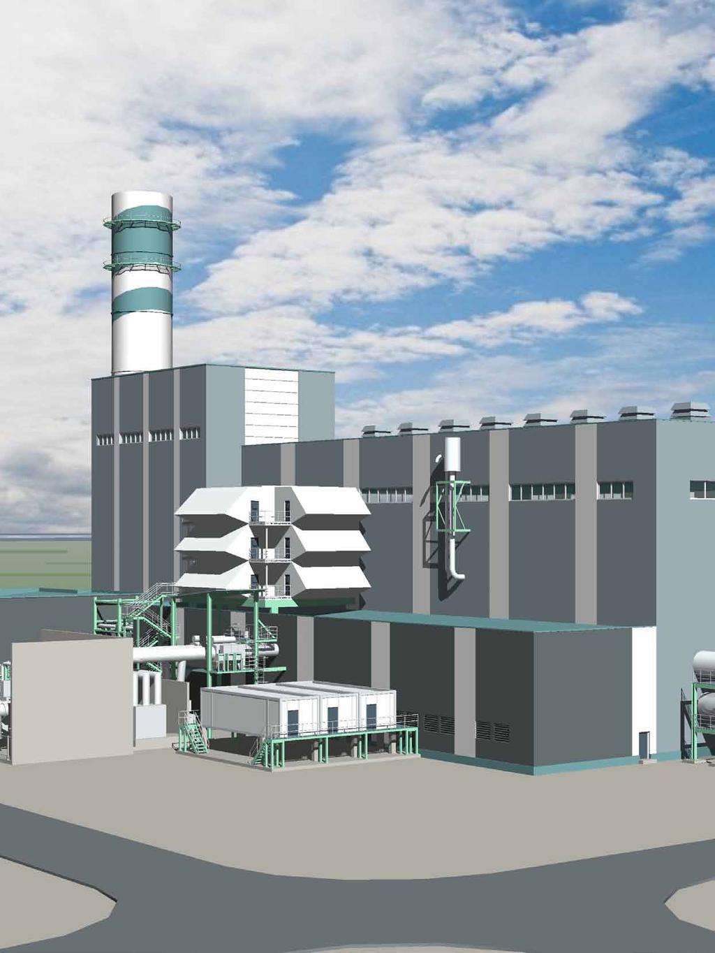
2 The first deployment of Siemens new path-breaking H class gas turbine and combined cycle technology in Asia will be at the LNG-fuelled Bugok site of GS EPS (Electric Power and Services) Ltd., project director, Siemens, Erlangen, Germany, and, VP, sales management Asia Pacific, Siemens, Offenbach, Germany S EPS, Korea s first independent power producer, founded in 1996 as an offshoot of LG, and now owned 70% by GS Holdings and 30% by Oman Oil, is continuing its track record of innovation. Unit 3 at the company s Bugok site will be one of the first power plants in the world to employ the new Siemens H class gas turbine, which makes possible a combined cycle efficiency of over 60% (LHV basis) but also provides considerable operational flexibility, enabling cycling and frequent and rapid starts/stops. Siemens, in consortium with GS E&C, is supplying the complete H class single-shaft combined cycle plant for unit 3, rated at >415 MWe gross, to GS EPS on a turnkey basis, with a scheduled commercial operation date of 31 August The turnkey contract was signed on 11 January 2011 and the groundbreaking ceremony for the new project, which represents an investment of about 460 billion won ($420 million), was held on 19 April Units 1 and 2 at the site (both 550 MWe multi-shaft (2-on-1) combined cycle plants, which entered commercial operation in July 2001 and March 2008, respectively) also employ Siemens gas turbines, of the earlier F class type.
 consists of 12 baskets with air cooled transitions.")


3 alignment of disks and hollow shaft sections to allow free radial expansion and contraction, and transmit the generated torque. The turbine rotor is internally air-cooled. The platform combustion system (PCS) consists of 12 baskets with air cooled transitions. The annular arrangement provides excellent uniformity of exhaust-gas temperature field over the full cross-sectional area of the turbine inlet. This is attributable to the fact that the 12 burners in the PCS form a continuous ring, thus eliminating hot and cold spots. The ultra low NO x technology suppresses thermal NO x formation without the need for injection of steam or water. The fuel for all three units at Bugok is LNG, and they all employ seawater cooling. Unit 3 will have an efficiency of >55% HHV basis, equal to >60% LHV basis. The scope of the unit 3 project, which employs a single shaft combined cycle configuration, includes the following: 60 Hz version of the Siemens H class gas turbine, SGT6-8000H (a direct aerodynamic scaling from the 50 Hz version, the SGT5-8000H, now in commercial operation at Irsching 4 in Germany, but with 12 can-combustors rather than 16). Irsching 4 has recently set a new world record for combined cycle efficiency, for the first time breaking the 60% efficiency barrier, see pp Hot commissioning of the lead SGT6-8000H machine, installed on the Siemens test bed in Berlin, started on 21 July As well as the Bugok 3 order, a further six SGT6-8000H machines have been ordered by US utility FPL. SST steam turbine with laterally installed condenser, coupled to the generator by SSS clutch. Common hydrogen cooled generator, SGen6-2000H type, for the steam and gas turbines. Triple pressure reheat heat recovery steam generator with HP once through (Benson type) boiler and natural circulation LP/IP boiler design, supplied as an indoor design within a boiler house. SPPA-T3000 plant control system with operator station integrated in the existing control room. Power control centres and electrical equipment such as isolated phase bus duct, generator circuit breaker, DC components and LV switchgear. Main and auxiliary transformer. New 345 kv grid connection employing GIS. New LNG connection including new gas pressure governor station. The fuel gas is delivered from the KOGAS terminal point via LNG piping, gas filtering, metering and preheating equipment, to the gas turbine fuel gas skid. The gas pressure at the terminal point to the power plant is >40 bar(g). New cooling water structures. New lifting and circulating water pumps. Extension of ancillary systems such as demineralised water and chlorination plant. The gas turbine (see also pp 23-27) The fully air-cooled model SGT6-8000H gas turbine, like the 50 Hz version, the SGT5-8000H, is a single-shaft machine of singlecasing design. The basic design, adopted from previous gas turbine models, includes the following features: disc-type rotor with central tie bolt and radial serrations; two journal bearings and one thrust bearing; generator drive at compressor intake end; and axial exhaust diffuser The rotor is supported by two journal bearings and one thrust bearing. The journal and thrust bearing are located at the compressor side, and the second journal bearing at the exhaust side of the turbine. The rotor is an assembly of disks, each carrying one row of blades, and hollow shaft sections, all held together by a pre-stressed central-tie bolt. Hirth serration provides the The generator The two-pole SGen6-2000H generator has direct radial hydrogen cooling for the rotor winding and indirect hydrogen cooling for the stator winding. The hydrogen filled generator casing is of pressure-resistant and gas-tight construction and is equipped with two end shields. The hydrogen cooler is divided into four sections, two arranged at each generator end. The three-phase winding inserted in the stator core slots is a two-layer transposed-bar design. The winding is vacuum pressure impregnated together with the stator core. The high-voltage insulation employs a proven proprietary epoxy-mica system. The generator rotor shaft is a vacuum-cast forging and has two end-shield sleeve bearings. The hydrogen is circulated in the generator interior in a closed circuit by axial flow fans arranged on the rotor shaft journals. A gas system contains all necessary equipment for filling, removal and operation of the generator with purging gas, hydrogen or air. A static (thyristor based) excitation system, including transformer, is used to take the excitation current from the auxiliary power system. A start-up frequency converter is provided for start-up of the turbine generator unit. The generator acts as a motor in the converter mode to start the gas turbine set without an additional rotating prime mover. Features of the generator include high efficiency and low maintenance costs. Steam turbine The tandem-compound steam turbine comprises one combined HP/IP casing and one double-flow low-pressure casing, with all components being standardised modules. With the compact design of the HP/IP turbine, hot steam conditions are confined to


4 the middle of the casing. On the other hand the glands at the casing ends are in regions of relatively cool steam conditions. Temperature decay is much slower when compared to a design with individual turbine casings. Consequently, the start-up times of such a compact turbine are significantly shorter, saving precious fuel. The design also requires less space, leading to savings with respect to the civil structures. The main feature of the LP turbine is the double shell inner casing, which can be displaced axially by means of pushrods. The differential expansion between rotor and casings is thus minimised under all operating conditions. Clutch To support flexible operation as well as the start-up procedure for the single-shaft combined cycle plant a self-synchronous clutch (SSS) is installed between the generator and steam turbine. With the gas turbine only driving the generator (during start-up) and the steam turbine at rest, the clutch is disengaged. Then, the steam turbine is accelerated and at the instant the steam turbine speed overtakes the generator, the relay clutch is engaged and transfers the steam turbine torque. Condensing plant The condenser is a box type surface condenser. The steam space is of a rectangular cross section in order to achieve optimum utilisation of the enclosed volume for the necessary condensing surface, formed of titanium tubing. The condenser is installed laterally at the LP turbine and forms an integral part of it. The steam dome, shell, hotwell, and the water boxes are steel fabrications. The condenser is fixed to the foundation beneath, with thermal expansion accommodated by means of Teflon pads. The double flow LP turbine outer casing is connected to the condenser via the steam dome. The steam dome is welded to the exhaust casing of the turbine with the result that the LP turbine cylinder and the condenser form one unit. Two water ring pumps with air jets (ELMO units) are installed for evacuation. During normal operation, only one pump is in operation. To shorten the evacuation time during start up both pumps can be put into operation. The heat recovery steam generator (HRSG) is located downstream of the gas turbine diffuser and as already mentioned produces steam in three pressure stages: high pressure; intermediate pressure; and low pressure. The exhaust gas flows horizontally through the HRSG. The plant features advanced steam conditions, with 150 bar and 585 C in the HP stage at the steam turbine nozzle. The HP steam generator is of the Benson type, with a once-through evaporator in the HP section, and natural circulation, drumtype evaporators in the IP and LP sections. A condensate preheater is integrated into the HRSG. This arrangement contributes to increasing the efficiency of the combined cycle plant by using exhaust gas energy to preheat the condensate before it passes towards the feed water pump and into the LP system. The boiler casing is made of steel plate as dictated by the prevailing exhaust gas temperatures. The HRSG is of the cold casing design with inside insulation. The HRSG is equipped with an outlet duct and steel stack at the end. The stack is fitted with a damper and a silencer. The top-supported heating surfaces consist mainly of finned tubes, which are suspended from a support structure. The heat recovery steam generator is designed to be located indoors and is contained in a boiler house, which also encloses the main working platforms. Each steam stage consists of an economiser (HP and IP), evaporator and superheater. The feedwater is heated in the economiser almost up to boiling temperature and fed into the superheater (HP section) or in the drum (IP section). From the IP drum, water is fed into the evaporator, where a portion is evaporated. The resulting water-steam mixture flows back to the drum where it is separated. The saturated steam is fed to the IP superheater where it is superheated up to main steam outlet temperature. The HP evaporator system is of the Benson forced flow design, so an HP drum is not needed. Instead a combined separator/water vessel is employed. During start-up and low load, a mixture of water and steam from the evaporator is introduced to the separator. Within the separator, the two phase flow is separated into water (fed to the water vessel) and steam (routed to the super-heaters). In the LP system, the condensate preheater heats the condensate to approximately the boiling temperature of the LP system. The LP feed water therefore goes directly from the condensate preheater to the LP drum. The HP steam is fed to the HP section of the steam turbine. The steam expands in the HP turbine and is fed back as cold reheat steam to the HRSG. There it is mixed with the superheated IP steam, superheated further in the reheater and then fed to the intermediate pressure section of the steam turbine. The HP and IP steam temperature is controlled by attemperation control. The generated LP steam is fed to the connection line from the outlet of the intermediate to the LP section of the steam turbine and the entire steam flow is completely expanded to vacuum in the LP steam turbine. For redundancy reasons the water steam cycle is furnished with 2 x 100% main condensate pumps and 2 x 100% feedwater pumps. The feedwater pumps are equipped with Voith variable speed couplings. A 2 x 50% condensate polishing plant is included. This is to prevent potential pollutant concentration, thus reducing corrosion and scaling/fouling in the turbine and superheater areas. The turbine exhaust steam is condensed by a seawater cooled condenser. The condensate and demineralised water accumulated in the condenser hotwell is discharged by one of the 2 x 100% condensate extraction pumps to the condensate preheating system. One condensate extraction pump operates during full load operation and a stand-by pump is ready to cut in automatically in case of failure of the operating pump. Deaeration of the condensate is mainly performed in the condenser under vacuum. The condensate extraction pump delivers the condensate from the condenser hotwell to the LP drum and to the suction side of the feedwater pumps via the condensate preheater of the HRSG. The condensate quality required for proper operation of the once through type heat recovery steam generator is ensured by the condensate polishing plant. Depending on the condensate quality the entire or only a part of the condensate mass flow can be supplied by the 2 x 50% condensate polishing pumps to the condensate polishing plant. The treated condensate is directly discharged to the suction side of the condensate extraction pumps.


5 COMBINED CYCLE Schematic process diagram A connection from the demineralised water distribution system is installed for filling of the pump discharge side and pressurising the condensate system during standstill. Downstream a line for the injection cooling of the intermediate pressure and low pressure bypass stations branches off. The feedwater is routed downstream of the HRSG condensate preheater in separate suction lines to the feedwater pumps via a strainer located upstream of each pump. An automatic recirculation check valve for the pump minimum flow requirement is located downstream of each feedwater pump. The minimum flow is returned to the condensate preheating system upstream of the condensate preheater. The HP pump discharge lines are connected to a common header, which delivers feedwater to the HP part of the HRSG. IP feedwater is tapped from a specific pump stage. The tapping lines are connected to a common header, which delivers the feedwater to the IP part of the HRSG. Another tapping point of the feedwater pump is used to recirculate feedwater via a common header to the condensate preheating system. Under normal operating conditions, feedwater is discharged by one of the two feedwater pumps via the HP/IP economisers of the HRSG into the HP evaporator and into the IP drum. The other pump is in stand-by. In case of failure of the operating feedwater pump, the standby pump cuts in automatically. The HP, IP and LP steam generated in the HRSG is fed to the steam turbine via the related steam piping system. The expanded HP steam is fed back to the boiler via the cold reheat line and is mixed with the superheated IP steam. All of the IP steam is superheated further in the reheater and fed to the IP section of the steam turbine. In order to achieve short start-up times and to control turbine trips a turbine bypass system is provided. The bypass system consists of the HP bypass connected to the cold reheat as well as the IP and LP bypass, both dumped to the condenser, and with related attemperation systems. The bypass control valves are equipped with hydraulic drives. A fuel gas preheating system preheats the fuel gas to approximately 215 C in order to increase the efficiency of the power plant. Accordingly, IP feedwater is extracted from the IP economiser and routed via the fuel gas preheater to the condensate preheating system upstream of the HRSG condensate preheater. Downstream of the fuel gas preheater a mass flow control valve is provided to control the fuel gas temperature at the outlet of the fuel gas preheater. To guarantee a sufficient mass flow through the preheater at part load and during preheater start-up conditions and to limit the temperature gradient at the preheater a recirculation pump is installed. This pump returns cold condensate from the outlet of the preheater to the inlet via a recirculation control valve. Auxiliary steam is supplied to the seal steam system of the steam turbine and to the evaporators of the HRSG for warming during plant standstill. The auxiliary steam piping system receives saturated steam either from the LP drum steam header or from the auxiliary boiler of the existing units depending on the operation mode of the plant. During normal combined cycle operation the auxiliary steam is delivered from the LP steam generating system. The cooling water system consists of 2 x 50% seawater lift pumps, 2 x 50% circulating water pumps as well as a 1 x 100 % seawater cooling pump. The circulating water system absorbs the heat from the steam surface condenser of the steam turbine, and transfers this heat to the seawater. Also, there is an additional seawater cooling pump which enables holding of vacuum and remaining cooling of the closed cooling water coolers during short downtimes of the power plant without the main cooling water pumps running. The service cooling water system Cutaway of Bugok 3

6 COMBINED CYCLE absorbs the heat from the closed cooling water system. The closed cooling water system, equipped with plate type heat exchangers, cools the equipment and components of the gas turbine, the steam turbine and the water/steam cycle. Electrical system The generator is connected to the generator transformer via an isolated phase busduct. A generator circuit breaker is installed between the generator and the tee-off connections to the unit auxiliary transformer, excitation transformer and static frequency converter transformer. The low voltage transformers and large motors are supplied from the medium voltage switchgear. An emergency AC supply system is provided ensuring the supply of AC power to essential loads in case of complete loss of the main AC power system. The uninterruptible power supply consists of 220 V DC battery and chargers, 125 V DC battery and chargers, 24 V DC (220/24 V DC/DC converters) and 460 V AC (inverter), 208/120 V AC (inverter) systems. The 220 V DC and 125V DC system provides power for designated consumers (eg, emergency oil pumps, protection, control voltage, inverter infeed). The 220V DC and 125V DC system consists of 2 x 100% battery chargers connected via individual fuses to one 100% battery. One battery charger is supplied from the normal AC system, the other one is supplied from the emergency diesel AC bus. The battery has an adequate capacity to supply the emergency loads for 1 hour. The 24 V DC system is powered via 2 x 100% redundant DC/DC converters. Their in-feed is taken from the 220 V DC battery system. Main consumers of 24 V DC are the DCS cabinets. The main control and monitoring functions of the electrical equipment are integrated into the DCS in order to minimise the required local control and monitoring activities. Also the main automatics and interlocks are realised in the DCS. Safety relevant interlocks, eg, grounding switches and protection, are hardwired. The DCS system automatic control program ensures that there is minimal need for manual intervention in the control of the electrical system. During start-up, the unit auxiliaries and the relevant station service loads are fed by the HV grid via the generator transformer and unit auxiliary transformer. The generator circuit breaker is open. The start-up sequence is automated by the main DCS. The gas turbine is accelerated by the start-up frequency converter with the generator in motor operation and minimum required excitation. After reaching synchronisation conditions and closing the generator breaker, the generator takes over the auxiliary power supply of the unit and provides power to the network. If the unit is in island operation (with the HV breaker open), it can be reconnected to the grid by closing the HV breaker under the supervision of the synchronisation equipment. During normal operation of the power plant, the auxiliary power will be provided by the generator via the unit auxiliary transformer. 3-tier architecture of the SPPA-T3000 During a normal shutdown, the generated power is reduced steadily until the generator circuit breaker or the HV circuit breaker can be opened. The auxiliary power is provided via the respective unit auxiliary transformer from the HV grid without interruption. In the case of an emergency shutdown caused by a main failure in the auxiliary power supply, the required power for a safe shut down is provided by the battery and the emergency AC supply system. Instrumentation and control The Bugok 3 combined cycle plant will be equipped with an SPPA-T3000 (Siemens Power Plant Automation Teleperm 3000) distributed control system. The system uses continuous information flow, consistent data management and storage, flexible instrumentation and control concepts, and uniform human machine interface (HMI) platforms to perform necessary automation, operational control, and data monitoring for the plant. The SPPA-T3000 DCS has a hierarchical structure. Design features include: a plantoriented process control structure that provides operational functions, combined with monitoring and diagnostic capability; a redundant, modular structure capable of future expansion by adding equipment as required; and an open local area network (LAN) structure for interfacing to other automation systems and external computer networks. The SPPA-T3000 DCS consists of a threetier architecture based on a server/client networking structure. The 100 Mbit Ethernet bus system provides the communication between the human machine interface, the automation servers and the application server that provides all necessary functions for plant engineering, operation monitoring, diagnostics and storing of process data. A basic concept of the system is the use of what are called embedded component services, which means that all processrelevant data is embedded into every single component. This component-embedded approach allows all data to be intrinsically available for operation, engineering or diagnostics. An important advantage of this structure is keeping the user interfaces ( thin clients ) independent of other applications. The thin clients present information regarding engineering, operation, and diagnostics and standard industrial PCs running just a web browser perform this task. The web-based system structure allows the use of a wide range of hardware such as standard PCs or notebooks that can run a web browser. The server/client structure means that HMI applications are available at multiple locations. There is no need for special hardware or software for engineering and operation functions. Terminals are identical in access capability. Limitations need be defined only by the authorisation system where the access rights are configured. This approach allows for highly flexible configurations for a wide range of power plant process control applications. The main benefits of the SPPA-T3000 software architecture are: consistent views at any time; only one data management location; integrated I&C, plant display, alarm, diagnostics and engineering; no code generation and separate down-loading activities; no subsystems such as engineering stations, operating stations and diagnostics computers. The SPPA-T3000 control system is functionally and physically distributed and is subdivided into functional areas to create a modular configuration. The functional separation is by major systems: gas turbine; steam turbine; heat recovery steam generator; water/steam cycle; and ancillary and auxiliary systems. Technology showcase The 60 Hz Bugok 3 plant, now under construction, will embody some of the most advanced features available today in combined cycle technology, producing over 415 MW on one shaft. The plant is capable of an efficiency of over 60% (LHV basis), with very advanced steam conditions. But at the same time it has immense operational flexibility, able to hot start in less than 30 minutes (hot start on the fly conditions), to deload very quickly and also to provide excellent frequency response capabilities. The HRSG with Benson type HP stage contributes to the fast cycling performance characteristics. Overall, Bugok 3 represents an optimal balance between capital costs, plant performance and operation & maintenance factors. MPS
7
8 This article appeared in: Modern Power Systems September 2011, Page Copyright 2011 by Modern Power Systems This reprint is published by: Siemens AG Energy Sector Freyeslebenstrasse Erlangen, Germany Siemens Energy, Inc Alafaya Trail Orlando, FL , USA For more information, please contact our Customer Support Center. Phone: / Fax: / (Charges depending on provider) support.energy@siemens.com Fossil Power Generation Division Order No. E50001-W220-A139-X-4A00 Printed in UK Dispo 05400, c4bs No TH MPS SD Printed on elementary chlorine-free bleached paper. All rights reserved. Trademarks mentioned in this document are the property of Siemens AG, its affiliates, or their respective owners. Subject to change without prior notice. The information in this document contains general descriptions of the technical options available, which may not apply in all cases. The required technical options should therefore be specified in the contract.
Operational flexibility enhancements of combined cycle power plants
 Operational flexibility enhancements of combined cycle power plants Reprint from Power-Gen Europe 2007 Authors: Dr. Norbert Henkel, Siemens Energy, Germany Erich Schmid, Siemens Energy, Germany Edwin Gobrecht,
Combined Cycle Power Plants. Combined Cycle Power Plant Overview (Single- and Multi-Shaft) Training Module. ALSTOM (Switzerland) Ltd )*+,
 Training Module. ALSTOM (Switzerland) Ltd )*+,") Power Plant Overview Training Module ALSTOM (Switzerland) Ltd )*+, We reserve all rights in this document and in the information contained therein. Reproduction, use or disclosure to third parties without
Power Plant Overview Training Module ALSTOM (Switzerland) Ltd )*+, We reserve all rights in this document and in the information contained therein. Reproduction, use or disclosure to third parties without
Flexible performance, convincing quality economical and future-proof packages
 siemens.com/energy Flexible performance, convincing quality economical and future-proof packages SGT5-PAC 4000F / SCC5-PAC 4000F Answers for energy. Competitive energy efficiency: packages for gas turbine
Steam Power Station (Thermal Station)
") Steam Power Station (Thermal Station) A generating station which converts heat energy into electrical energy through turning water into heated steam is known as a steam power station. A steam power station
Steam Power Station (Thermal Station) A generating station which converts heat energy into electrical energy through turning water into heated steam is known as a steam power station. A steam power station
SGT-8000H gas turbine series proven in commercial operations
 High efficiency, low emissions, fast start-up capability SGT-8000H gas turbine series proven in commercial operations siemens.com/gasturbines SGT-8000H turbine series: Proven, efficient, reliable The proven
STEAM TURBINE-GENERATOR & AUXILLIARY SYSTEMS Presentation by: RANA NASIR ALI General Manager, Power Plants Projects, at PITCO November 02, 2017
 STEAM TURBINE-GENERATOR & AUXILLIARY SYSTEMS Presentation by: RANA NASIR ALI General Manager, Power Plants Projects, at PITCO November 02, 2017 CO-GENERTATION POWER PLANT CONCEPT For dimensioning, design
Steam Turbines. Leading Technology for Efficient, Reliable Generation Siemens Steam Turbines from 90 MW up to 1,900 MW.
 Steam Turbines Leading Technology for Efficient, Reliable Generation Siemens Steam Turbines from 90 MW up to 1,900 MW Power Generation A comprehensive product line with proven experience Proven modular
Your partner for the right solution
 Your partner for the right solution Project engineering of power stations Environment protection in energy sector Equipment supplying Supervision of installation of the equipment supplied Commissioning
Industrial Power. SGT-800 Gas Turbine. Power Generation: (ISO) 47.5 MW(e) / 50.5 MW(e) / energy
 47.5 MW(e) / 50.5 MW(e) / energy") Industrial Power SGT-800 Gas Turbine Power Generation: Simple Cycle Combined Cycle 2x1 (ISO) 47.5 MW(e) / 50.5 MW(e) (ISO) 135.4 MW(e) / 143.6 MW(e) www.siemens.com / energy Nomenclature SC: CC: SCC: DLE:
Industrial Power SGT-800 Gas Turbine Power Generation: Simple Cycle Combined Cycle 2x1 (ISO) 47.5 MW(e) / 50.5 MW(e) (ISO) 135.4 MW(e) / 143.6 MW(e) www.siemens.com / energy Nomenclature SC: CC: SCC: DLE:
NUCLEAR TRAINING CENTRE COURSE 134 FOR ONTARIO HYDRO USE ONLY
 NUCLEAR TRAINING CENTRE COURSE 134 FOR ONTARIO HYDRO USE ONLY NUCLEAR TRAINING COURSE COURSE 134 1 - Level 3 - Equipment & System Principles 4 - TURBINE, GENERATOR & AUXILIARIES Index 134.00-0 Objectives
Appendix B. Glossary of Steam Turbine Terms
 Operator s Guide to General Purpose Steam Turbines: An Overview of Operating Principles, Construction, Best Practices, and Troubleshooting. Robert X. Perez and David W. Lawhon. 2016 Scrivener Publishing
Course 0101 Combined Cycle Power Plant Fundamentals
 Course 0101 Combined Cycle Power Plant Fundamentals Fossil Training 0101 CC Power Plant Fundamentals All rights reserved. No part of this publication may be reproduced, distributed, or transmitted in any
Equipment Design. Detailed Plant Conceptual Design. Version 9.0
 Equipment Design Version 9.0 Detailed Plant Conceptual Design SOAPP CT sizes all major plant equipment, based on your Project Input, the process configuration derived from this input, and the results of
POWER-GEN MIDDLE EAST DOHA, QATAR FEBRUARY 4th -6th 2013
 POWER-GEN MIDDLE EAST DOHA, QATAR FEBRUARY 4th -6th 2013 Siemens Expands Footprint in the Middle East with SGT6-5000F Power Plant Solutions and New Gas Turbine Manufacturing Facility Adam Foust Siemens
CHAPTER 2 STUDY OF 210 MW BOILER SYSTEM 2.1 DESCRIPTION OF 210 MW BOILER
 8 CHAPTER 2 STUDY OF 210 MW BOILER SYSTEM 2.1 DESCRIPTION OF 210 MW BOILER Detailed study has been carried out on a 210 MW boiler system with regard to model development, control and optimization. Figure
ORC TURBOGENERATOR TYPE CHP - Organic Rankine Cycle Turbogenerator fed by thermal oil, for the combined production of electric energy and heat -
 Doc. : 08C00031_e Date : 02.02.2009 Page : 1 / 9 ORC TURBOGENERATOR TYPE CHP - Organic Rankine Cycle Turbogenerator fed by thermal oil, for the combined production of electric - (Preliminary) Doc. : 08C00031_e
High Bridge Combined Cycle Plant
 High Bridge Combined Cycle Plant Location: Down town St. Paul, on the Mississippi River Plant Description: High Bridge is a combined cycle generating facility. A combined cycle plant produces electricity
INTRODUCING THE SGCC6-5000F 2x1 REFERENCE POWER BLOCK FOR IGCC APPLICATIONS
 INTRODUCING THE SGCC6-5000F 2x1 REFERENCE POWER BLOCK FOR IGCC APPLICATIONS Gerald J. Feller, Ph.D., Siemens Power Generation, Inc. 4400 Alafaya Trail Q2-284, Orlando, Florida 32826, Phone: 407-736-2237/E-Mail:
360 vision page 13. Air-cooled evolution page 18. 3D testing page 22. Patriot gains page 26
 360 vision page 13 Air-cooled evolution page 18 3D testing page 22 Patriot gains page 26 March - April 2017 Patriot designed to monetize Marcellus shale gas by Junior Isles The Panda Patriot power plant
Equipment Design. Detailed Plant Conceptual Design. Version 7.0
 Equipment Design Version 7.0 Detailed Plant Conceptual Design SOAPP CT sizes all major plant equipment, based on your Project Input, the process configuration derived from this input, and the results of
SUMMER 15 EXAMINATION
 SUMMER 15 EXAMINATION Subject Code: 17413 ( EME ) Model Answer Important Instructions to examiners: 1) The answers should be examined by key words and not as word-to-word as given in the model answer scheme.
Power Engineering II. Technological circuits of thermal power plants
 Technological circuits of thermal power plants Lay out scheme of coal power plant climatetechwiki.com Technological circuits 2 Coal and ash circuit Air and gas circuit Feed water and steam circuit Cooling
High efficient peak power on demand. Answers for energy.
 www.siemens.com/energy High efficient peak power on demand POWER-GEN Asia 2011 KLCC, Malaysia, Kuala Lumpur September 27 29, 2011 Authors: Jan Dirk Beiler Siemens AG Energy Sector Fossil Power Generation
District Heatingwithor. C For Additional And Cleaner POWER. ISCC and Solar Boost. Conference Paper CONFERENCE PAPER
 Combining Combined Steam ISCC and Solar Boost Solar Cycles Power District Heatingwithor Plants with theproject Flexibility of the 1300 MW Repowering Claus Technical Paper KA26 Combined Cycle Power Plant
Main Steam & T/G Systems, Safety
 Main Steam & T/G Systems, Safety Page 1 This steam generator, built for the Wolsong station in Korea, was manufactured in Canada by the Babcock and Wilcox company. In Wolsong 2,3, and 4 a joint venture
PEMP RMD & Cycle Performance. M.S.Ramaiah School of Advanced Studies
 Steam Se Turbine ub ecyces Cycles & Cycle Performance Session delivered by: Prof. Q.H. Nagpurwala 1 Session Objectives This session is intended to discuss the following: Basic construction and classification
Pre-designed Steam Turbines. The comprehensive product range up to 10 megawatts. Answers for energy.
 Pre-designed Steam Turbines The comprehensive product range up to 10 megawatts Answers for energy. A Full Range of World-class Industrial Steam Turbines Whatever your need for a prime mover, Siemens can
siemens.com/gasturbines Reliable and powerful economical, safe-investment packages SGT6-PAC 5000F / SCC6-PAC 5000F
 siemens.com/gasturbines Reliable and powerful economical, safe-investment packages SGT6-PAC 5000F / SCC6-PAC 5000F SGT6-PAC 5000F packages: flexible answers to drive your business forward Innovation for
Turbine Island. Nhan Huynh Project Manager, Turbine and its auxiliary systems
 Turbine Island Nhan Huynh Project Manager, Turbine and its auxiliary systems 1 Content 1 Fennovoima in brief 2 Project development roadmap 3 Main sub-suppliers 4 Scope of supply 5 Turbine and auxiliaries
Full Steam ahead for Flamanville 3 EPR turbine island construction
 May 2010 Full Steam ahead for Flamanville 3 EPR turbine island construction POWER The 1750 MWe ARABELLE turbine generator is the world s largest engine. The first such machine in Europe is currently under
Waste Heat Recovery with Organic Rankine Cycle Technology
 Power Generation Waste Heat Recovery with Organic Rankine Cycle Technology Power Generation with the Siemens ORC-Module Scan the QR code with the QR code reader in your mobile! www.siemens.com / energy
MEC-MOS-E-2004 Gas Turbine Maintenance Engineer PERSONAL DATA EDUCATION LANGUAGES COMPUTER SKILLS TRAINING COURSES AND CERTIFICATIONS
 100771-MEC-MOS-E-2004 Gas Turbine Maintenance Engineer Holds a B. Sc. and M. Sc. in Mechanical Power Engineering. Has about 11 years hands-on experience in power plant projects including installation for
The H-25/H-15 Gas Turbine A Product of Hitachi Quality
 DMLieferant www.dmliefer.ru The H-25/H-15 Gas Turbine A Product of Hitachi Quality The H-25 s fuel savings will repay your investment within a few years while allowing you a range of fuels from distillate
2. TECHNICAL DESCRIPTION OF THE PROJECT
 2. TECHNICAL DESCRIPTION OF THE PROJECT 2.1. What is a Combined Cycle Gas Turbine (CCGT) Plant? A CCGT power plant uses a cycle configuration of gas turbines, heat recovery steam generators (HRSGs) and
VVER-440/213 - The reactor core
 VVER-440/213 - The reactor core The fuel of the reactor is uranium dioxide (UO2), which is compacted to cylindrical pellets of about 9 height and 7.6 mm diameter. In the centreline of the pellets there
20/06/2011 Seminar on Geothermal Exploitation Santiago de Chile
 Contents Power Plants Steam Power plants Binary Power plants Geothermal Power Plants Single flash systems Binary systems 1 Equipment Well head Gathering piping system Steam separators and moisture separators
Low Emission Water/Steam Cycle A Contribution to Environment and Economics. Peter Mürau Dr. Michael Schöttler Siemens Power Generation, (PG) Germany
 Germany") Low Emission Water/Steam Cycle A Contribution to Environment and Economics Peter Mürau Dr. Michael Schöttler Siemens Power Generation, (PG) Germany Page 1 of 17 Abstract Avoiding emissions is a general
Low Emission Water/Steam Cycle A Contribution to Environment and Economics Peter Mürau Dr. Michael Schöttler Siemens Power Generation, (PG) Germany Page 1 of 17 Abstract Avoiding emissions is a general
NOTICE CONCERNING COPYRIGHT RESTRICTIONS
 NOTICE CONCERNING COPYRIGHT RESTRICTIONS This document may contain copyrighted materials. These materials have been made available for use in research, teaching, and private study, but may not be used
Products and customer service
 Products and customer service Supplier of Equipment and Services for Power Generation Technology quality products / our people / smart solutions / advanced technology Doosan Škoda Power Part of Doosan
Yokogawa generic 416MW Combined Cycle Power Plant Simulator
 Yokogaw a Australia Pty Ltd A. B. N. 3 6 0 0 3 8 8 8 3 6 4 Y o k o g a w a S i m u l a t i o n A D i v i s i o n o f Y o k o g a w a A u s t r a l i a P t y L t d T o w e r A, 1 1 2-1 1 8 T a l a v e r
Heat Recovery Steam Generators for Flexibility
 Heat Recovery Steam Generators for Flexibility Landon Tessmer IAGT October 2016 Overview The grids needs flexible power HRSG and OTSG Designs Supplementary Firing Fresh Air Firing Case Study Balance of
UK ABWR Generic Design Assessment Generic PCSR Chapter 17 : Steam and Power Conversion Systems
 Form10/00 Document ID Document Number Revision Number : : : GA91-9101-0101-17000 SBE-GD-0054 C Generic Design Assessment Generic PCSR Chapter 17 : Steam and Power Conversion Systems Hitachi-GE Nuclear
FLEXI BURN CFB WP4: Boiler design and performance
 Development of High Efficiency CFB Technology to Provide Flexible Air/Oxy Operation for Power Plant with CCS FLEXI BURN CFB WP4: Boiler design and performance 2 nd Project Workshop, 6 th February 2013,
The H-25/H-15 Gas Turbine A Product of Hitachi Quality
 GKKP-08-012 Rev.0 The H-25/H-15 Gas Turbine A Product of Hitachi Quality The H-25 s fuel savings will repay your investment within a few years while allowing you a range of fuels from distillate to natural
Double Reheat Technology
 www.siemens.com/energy Double Reheat Technology The next step to optimized efficiency Answers for energy. Modern Steam Power Plants: On the Path to Increased Efficiency The requirements of power suppliers
Unit No.4-1 Higashi Niigata Thermal Power Station Operating Status O C Class Gas Turbine Operation -
 101 Unit No.4-1 Higashi Niigata Thermal Power Station Operating Status - 1450 O C Class Gas Turbine Operation - Yoshiaki Tsukuda *1 Eiji Akita *1 Yoichi Iwasaki *1 Koichiro Yanou *1 Yutaka Kawata *2 Toshihide
Fuji Electric s Medium-capacity Steam Turbines FET Series
 Fuji Electric s Medium-capacity Steam Turbines FET Series Koya Yoshie Michio Abe Hiroyuki Kojima 1. Introduction Recently, de-regulation of the electric power industry and rising needs for advanced solutions
Integrated Plant Control DCS
 Integrated Plant Control DCS geautomation.com Why Choose GE s Integrated Plant Control DCS System? GE s Integrated Plant Control DCS (Distributed Control System) is a solution for managing complex plant
Benefits. Reduced transportation time and cost. Limited on-site inventory. Minimal installation time. Efficient commissioning
 Gas Turbine Package Gas Turbine Package Gas turbine package is available in both single- and twinengine configurations, which offer greater than 41 percent simple-cycle efficiency and a nominal 60 to 140
Copyright 1984 by ASME COGENERATION - INTERACTIONS OF GAS TURBINE, BOILER AND STEAM TURBINE
 S THE AMERICAN SOCIETY OF MECHANICAL ENGINEERS 345 E. 47 St., New York, N.Y. 10017 L+ C The Society shall not be responsible for statements or opinions advanced in papers or in C. discussion at meetings
GAS-FIRED COMBINED-CYCLE POWER PLANTS HOW DO THEY WORK? A company of
 GAS-FIRED COMBINED-CYCLE POWER PLANTS HOW DO THEY WORK? A company of Cover picture: Gas turbine compressor with combustion chamber CONTENTS At a glance.................................................
Environmental Impact Assessment (Annexes 1 9b)
") Environmental Impact Assessment (Annexes 1 9b) May 2016 Bangladesh: Power System Expansion and Efficiency Improvement Investment Program (Tranche 3) Ashuganj 400 MW Combined Cycle Power Plant (East) Prepared
Environmental Impact Assessment (Annexes 1 9b) May 2016 Bangladesh: Power System Expansion and Efficiency Improvement Investment Program (Tranche 3) Ashuganj 400 MW Combined Cycle Power Plant (East) Prepared
Combined Cycle Power
 POWER GENERATION Combined Cycle Power Combined cycle power utilizing the gas turbine (Brayton Cycle) and the steam system (Rankine Cycle) are a lethal weapon against news worthy coal fired emissions worldwide.
6.1 Introduction. Control 6-1
 Control 6-1 Chapter 6 Control 6.1 Introduction Although the bulk of the process design of the Heat Transport System is done prior to the control design, it is helpful to have the key features of the control
Steam Turbines. A Finmeccanica Company
 Steam Turbines A Finmeccanica Company Steam Turbines Ansaldo Energia has a comprehensive steam turbine offering covering a wide range of power generation applications: Geothermal steam turbines Cogeneration
PROJECT MONITORING ENGINEERING RISK SPECIALISTS. Introduction. Project Delay In Start Up Monitoring
 ENGINEERING RISK SPECIALISTS PROJECT MONITORING Introduction Project Delay In Start Up M onitoring Potential Exposure Schedule/Construction Sequence Claims Critical Equipment/Materials Critical Equipment
Industrial Power. Pre-designed Steam Turbines. The comprehensive product range up to 12 megawatts. / energy
 Industrial Power Pre-designed Steam Turbines The comprehensive product range up to 12 megawatts www.siemens.com / energy A Full Range of World-class Industrial Steam Turbines Whatever your need for a prime
PRODUCT DESCRIPTION PARAMETERS
 PRODUCT SHEET PRODUCT DESCRIPTION PARAMETERS Steam boilers PB-P PB-PP PB-NP Moderated-pressure three-pass steam boilers combusting gaseous and liquid fuels in the saturated steam and superheated steam
Kawasaki Gas Turbines-Americas Gas Turbines Power Generation Technology & Applications
 Kawasaki Gas Turbines-Americas Gas Turbines Power Generation Technology & Applications Gas Turbine (GT) Technology Overview Gas Turbine Theory GT - Centrifugal Compressor FUEL INLET COMBUSTION CHAMBER
Nuclear Power A Journey of Continuous Improvement
 Nuclear Power A Journey of Continuous Improvement Westinghouse Non Proprietary Class 3 Our Place in Nuclear History Innovation 1886 and forever Implementation & Improvement 1957 through Today Renaissance
Combined Heat and Power
 Lecture 12 Combined Heat and Power Combustion Turbines and Co-generation Combustion Turbines and Combined Heat and Power (CHP) Systems See B. K. Hodge, Chapter 5 and Chapter 11. ISBN: 978-0-470-14250-9
Han MK, Business Development (Power Generation), 23rd March 2010 ABB Power and Automation Days ABB in Power Generation
, 23rd March 2010 ABB Power and Automation Days ABB in Power Generation") Han MK, Business Development (Power Generation), 23rd March 2010 ABB Power and Automation Days ABB in Power Generation Content ABB Power Generation ABB Solutions for Power Generation ABB Solutions for
Han MK, Business Development (Power Generation), 23rd March 2010 ABB Power and Automation Days ABB in Power Generation Content ABB Power Generation ABB Solutions for Power Generation ABB Solutions for
Innovative Control Strategies Improve Boiler Dynamic Response
 Innovative Control Strategies Improve Boiler Dynamic Response by M. Rech, J. Rupp and K. Wendelberger Reprint from COAL POWER magazine November 7, 2008 Answers for energy. Innovative Control Strategies
Pratt & Whitney. Power Systems MOBILEPAC. Gas Turbine Package. It s in our power.
 Power Systems Pratt & Whitney Power Systems MOBILEPAC Gas Turbine Package TM It s in our power. Pratt & Whitney FT8 MOBILEPAC Gas Turbine Package The MOBILEPAC gas turbine package requires the smallest
Innovative Boiler Design to Reduce Capitel Cost and Construction Time
 s Innovative Boiler Design to Reduce Capitel Cost and Construction Time Presented originally at Power-Gen 2000 Authors: Joachim Franke Rudolf Kral Power for Generations Siemens Power Generation Content
5.2 MW Solar Mobile Power Unit
 5.2 MW Solar Mobile Power Unit Ventilation air intake Ventilation air exhaust Air inlet & silencer Exhaust Silencer Power Control Room & Trailer -13.8 KV switchgear -CO2 fire system -480 VAC MCCC for turbine
Update on the operational experience of the H-class power plants fleet, including South Korea s first commercial unit Dangjin3
 PowerGen Asia, Bangkok, Thailand October 2 4, 2013 Update on the operational experience of the H-class power plants fleet, including South Korea s first commercial unit Dangjin3 Dr. Kais Sfar, Siemens
Completion of Hitachi Rinkai Power Station Unit-2
 Completion of Hitachi Rinkai Power Station Unit-2 94 Completion of Hitachi Rinkai Power Station Unit-2 Hidekazu Takai Fumiharu Moriwaki Tsutomu Tanakadate Makoto Funaki OVERVIEW: In recent years, thanks
Gas-insulated medium-voltage switchgear. for marine and offshore applications. Answers for energy.
 Gas-insulated medium-voltage switchgear for marine and offshore applications Answers for energy. 8DH10 switchgear up to 24 kv, up to 20 ka, up to 1,250 A up to 17.5 kv, up to 25 ka, up to 1,250 A Full
The Prescriptive Promise
 Next Generation Asset Management Turning industrial trends and patterns from noise into action Industrial Data What Is It? 1 Definition 2 Example data sources Time series Sensor devices High velocity Temperature
Prohibition of Boiler Feed Water Pump Failure in Power Plant
 Int J Advanced Design and Manufacturing Technology, Vol. 5/ No. 5/ December - 2012 77 Prohibition of Boiler Feed Water Pump Failure in Power Plant B. Soleimani Roody Bandar Abbas Power Plant, Iran E-mail:
Development of Large-Capacity Single-Casing Reheat Steam Turbines for Single-Shaft Combined Cycle Plant
 Development of Large-Capacity Single-Casing Reheat Steam Turbines for Single-Shaft Combined Cycle Plant TAKASHI NAKANO*1 TAMIAKI NAKAZAWA*1 KENYU TAKEDA*1 KEIZO TANAKA*1 SHIN NISHIMOTO*1 TOSHIHIRO MIYAWAKI*2
Recent Technologies for Steam Turbines
 Recent Technologies for Steam Turbines Kenji Nakamura Takahiro Tabei Tetsu Takano A B S T R A C T In response to global environmental issues, higher efficiency and improved operational reliability are
AP1000 European 15. Accident Analysis Design Control Document
 15.2 Decrease in Heat Removal by the Secondary System A number of transients and accidents that could result in a reduction of the capacity of the secondary system to remove heat generated in the reactor
THERMAL AND HYDRAULIC MACHINES UNIT 2
 THERMAL AND HYDRAULIC MACHINES UNIT 2 A steam turbine is a device that extracts thermal energy from pressurized steam and uses it to do mechanical work on a rotating output shaft. Its modern manifestation
Blackstone: flexible and environmentally friendly power plant
 May-June 2002 Turbomachinery Blackstone: flexible and environmentally friendly power plant INTERNATIONAL Two single shaft combined cycle blocks - each with centrally-mounted generator and SSS Clutch Blackstone:
Downsizing a Claus Sulfur Recovery Unit
 INFRASTRUCTURE MINING & METALS NUCLEAR, SECURITY & ENVIRONMENTAL Downsizing a Claus Sulfur Recovery Unit OIL, GAS & CHEMICALS By Charles L. Kimtantas and Martin A. Taylor ckimtant@bechtel.com & mataylo1@bechtel.com
NSSS Design (Ex: PWR) Reactor Coolant System (RCS)
 Reactor Coolant System (RCS)") NSSS Design (Ex: PWR) Reactor Coolant System (RCS) Purpose: Remove energy from core Transport energy to S/G to convert to steam of desired pressure (and temperature if superheated) and moisture content
NSSS Design (Ex: PWR) Reactor Coolant System (RCS) Purpose: Remove energy from core Transport energy to S/G to convert to steam of desired pressure (and temperature if superheated) and moisture content
Process Compressors. Designed to optimize your business. Answers for energy.
 Process Compressors Designed to optimize your business Answers for energy. Turbocompressors from Siemens covering the complete spectrum Siemens offers a full range of turbocompressors to meet the needs
Siemens Steam Turbine SST-600
 Siemens Steam Turbine SST-600 This PDF offers an advanced interactive experience. For the best viewing experience, please use Acrobat Reader X or higher. Version 3 Siemens SST-600: Highly-versatile Generator
WASTE HEAT BOILERS FOR NITRIC ACID, CAPROLACTAM AND FORMALDEHYDE PLANTS
 WASTE HEAT BOILERS FOR NITRIC ACID, CAPROLACTAM AND FORMALDEHYDE PLANTS BORSIG The Company BORSIG Process Heat Exchanger GmbH, a member of the BORSIG Group, is the international leading manufacturer of
SOAPP-CT Version 8.0 Released
 SOAPP-CT Version 8.0 Released Powerful Tool Integrates Technical and Financial Decision Making Palo Alto, February 13, 2007: EPRI has announced the release of SOAPP-CT Version 8.0. SOAPP-CT provides integrated
Gas turbines have been used for electricity generation. Gas turbines are ideal for this application as they can be started and stopped quickly.
 WE LCOME Gas turbines have been used for electricity generation. Gas turbines are ideal for this application as they can be started and stopped quickly. There are two basic types of gas turbines Aero derivative
Custom Systems Built to Exacting Client Specification
 Custom Systems Built to Exacting Client Specification Laboratory Reactor Systems Parr Instrument Company is pleased to work with customers in the design and assembly of complete laboratory or pilot plant
Heating Iron Ore Slurry to Improve Filtering Efficiency Prior to Pelletizing
 Heating Iron Ore Slurry to Improve Filtering Efficiency Prior to Pelletizing Robert E Wood Inproheat Industries Ltd. Wesley Young, P. Eng Inproheat Industries Ltd. Abstract Engineers have known for some
TCN 02, Dated: WITH REFERENCE TO ABOVE FOLLOWING CHANGES MAY PLEASE BE NOTED AND COMPLIED WHILE SUBMITTING THE OFFER FOR THE SUBJECT JOB:
 Bharat Heavy Electricals Limited (A Government of India Undertaking) Power Sector Eastern Region Plot No. 9/, Block-DJ, Salt Lake City, Kolkata 700 09 (INDIA) Phone no. 033-232 69 Fax : 033-232 960 Web
Medium Voltage UPS Solutions - When and Why? Frank Herbener, Piller Group GmbH, Germany
 Medium Voltage UPS Solutions - When and Why? Frank Herbener, Piller Group GmbH, Frank.Herbener@Piller.com, Germany 1 Contents 1 Scope 3 2 Power Demand and Distribution in today s Mission Critical Applications
The following sub-systems are provided and the integration of these is described below:
 The following sub-systems are provided and the integration of these is described below: Pretreatment Plant The Pretreatment Plant typically comprises an amine system for gas sweetening and a molecular
SCHNEIDER-KESSEL BERLIN
 SCHNEIDER-KESSEL BERLIN STEAM BOILER and HOT WATER BOILER WASTE HEAT RECOVERY BOILER - Series AHK GENERAL Waste Heat Recovery boilers of Series AHK are steam generators in special smoke tube design to
Towards New Milestones In CFB Boiler Technology CFB 800MWe
 Towards New Milestones In CFB Boiler Technology CFB 800MWe Arto Hotta, Kari Kauppinen, Ari Kettunen Foster Wheeler Energia Oy Finland Presented at Coal Gen Europe Warsaw, Poland February 14 16, 2012 ABSTRACT
SOME ENERGY-EFFICIENT TECHNOLOGIES IN JAPAN
 SOME ENERGY-EFFICIENT TECHNOLOGIES IN JAPAN (EXECUTIVE SESSION) November, 2007 JAPAN EXTERNAL TRADE ORGANIZATION JAPAN CONSULTING INSTITUTE SOME ENERGY-EFFICIENT TECHNOLOGIES IN JAPAN 1. Power Generation
A class of its own JUMAG STEAM BOILER COMPACT INFORMATION STEAM BOILER WATER SUPPLY MODULES BLOW DOWN VESSEL COMPACT STEAM SYSTEM.
 A class of its own JUMAG STEAM BOILER COMPACT INFORMATION STEAM BOILER WATER SUPPLY MODULES BLOW DOWN VESSEL COMPACT STEAM SYSTEM www.jumag.de OIL OR GAS FIRED STEAM BOILER A class of its own Steam within
Carrington Power Station
 Carrington Power Station INTRODUCTION 01 Welcome to Carrington Power Station Carrington Power Station is a 884.2MW plant that generates enough electricity to power more than one million homes and businesses.
Exhaust Heat Recovery Systems
 Exhaust Heat Recovery Systems Boiler Economizer Systems Gas & Diesel Cogeneration Systems Fume Incineration Systems Finned Tubing The Cain Industries Family of Heat Recovery Systems 030717 Cain Industries
LOGISTIC PROCESSES IN A COAL FIRED POWER PLANT
 LOGISTIC PROCESSES IN A COAL FIRED POWER PLANT Dušan SOJČÁK, František BRUMERČÍK 1 Introduction The purpose of this article is to shortly describe and provide basic information of the logistic processes
Circulating Fluidized Bed Technology Towards 800 MWe Scale Lagisza 460 MWe Supercritical CFB Operation Experience
 Circulating Fluidized Bed Technology Towards 800 MWe Scale Lagisza 460 MWe Supercritical CFB Operation Experience Timo Jäntti, Kimmo Räsänen Foster Wheeler Energia Oy Varkaus, Finland Presented at Power
The Locomotive. A Copper-Plated Thief: The Problem of Copper Deposits in Turbines
 A Copper-Plated Thief: The Problem of Copper Deposits in Turbines By Dave Daniels and John Latcovich, The Hartford Steam Boiler Introduction Operators at a coal-fired, 2,600 PSI power plant performed monthly
UC Davis - Facilities O&M Cogeneration Plant Bid Package October, 2007
 UC Davis - Facilities O&M Cogeneration Plant Bid Package October, 2007 I. Cogeneration Plant Overview The University has owned and operated a cogeneration system since 1981, though nearly all of the original
H-Class Combined Cycle Power Plants
 Power-GEN Asia H-Class Combined Cycle Power Plants Amir Mujezinovic Kuala Lumpur, Malaysia 9-12, September 2014 GE Power & Water 2014, General Electric Company. GE Proprietary Information - The information
Pre-owned 240 MW Combined Cycle Gas Turbine Power Plant
 P.O.Box 130571 20105 Hamburg/Germany For Sale: Ref.-No: Tel. +49 40 33441944 Fax +49 40 33441945 Pre-owned 240 MW www.lohrmann.com info@lohrmann.com Combined Cycle Gas Turbine Power Plant GT-CC-045 (short)