OWNER'S OPERATING MANUAL
|
|
|
- Arabella Burke
- 6 years ago
- Views:
Transcription


1 OWNER'S OPERATING MANUAL FN Series TM Rackmount UPS Plus Parallel or N+1 Redundant 3kVA to 24kVA Hardwire models with a Vac Input and 120Vac, 208Vac & 240Vac Outputs Uninterruptible Power Supply Models: FN3KRM-2, -2TX & -2TXI FN4KRM-2, -2TX & -2TXI FN5KRM-2, -2TX, & -2TXI FN6KRM-2, -2TX & -2TXI FN8KRM-2, -2TX & -2TXI FN10KRM-2, -2TX & -2TXI FALCON Electric, Inc., 5116 Azusa Canyon Rd., Irwindale, California 91706, (626) , Fax (626) , sales@falconups.com 2011 Falcon Electric Inc. All rights reserved. All other brand names and trademarks are the property of their respective owners. The information stated in this document is subject to change without notice Falcon, Falcon Electric, FN and UPS Plus logos are registered trademarks of Falcon Electric, Inc.
2 TABLE OF CONTENTS FN Rackmount Series Parallelable and N+1 Redundant UPS Features FN -2TX Double-Conversion On-line UPS Block Diagram Important Safety Instructions (READ FIRST) Chapter 1. Introduction 1.1 Manual Overview Brief FN Overview Chapter 2. FN UPS Circuit Descriptions Galvanically Isolated Output Input & Power Factor Correction Power Factor Correction DC/DC Converter DC/AC Inverter Battery Packs Internal Battery Charger Static Bypass Function Automatic Bypass Transfers Output FIlter Chapter 3. Unpacking the UPS and Battery Bank 3.1 Unpacking Instructions Chapter 4. Pre-installation Details 4.1 Floor Loading Requirements UPS Input Power Requirements UPS Input/Output Requirements UPS Output Rating Details FN 3-6kVA System Rear Panel Overview FN8-10kVA System Rear Panel Overview kVA Hardwire Terminal Block Wiring Details UPS Rear Panel Details kVA System Installation Wiring Diagram, Single UPS Unit kVA System Installation Wiring Diagram, Multiple Parallel UPS Units UPS & Transformer Module Communications Bus Cabling kVA System Installation Wiring Diagram, Typical External Battery Charger Option Installation Chapter 5. Displays & Controls 5.1 Control Button and LCD Locations Control Button Operation LED Display Modes LCD Display Overview LCD Icon Descriptions Status & Error Code Descriptions Chapter 6. Operation 6.1 How to start up the UPS with utility power present How to start up the UPS without utility power present How to turn off the UPS inverter and place the UPS into bypass mode How to completely shutdown the UPS How to display Readings How to display Programmed Settings How to change the Programmed Settings How to use the Maintenance Bypass Switch Chapter 7. Communications 7.1 Advanced Communications Option Cards Available RS-232 Port Optional Remote Emergency Power Off Optional Communications Interface Board Details Chapter 8. Maintenance 1. UPS & Battery Care Storing the UPS and Batteries When to Replace Batteries Chapter 9. Parallel Mode Operation 9.1 How to configure FN models for Transformer Module, Parallel or N+1 Communications How to connect the FNB Battery Module to the UPS Module Chapter 10. Environmental 10.1 Recycling the Used Battery Packs FCC Considerations Chapter 11. Technical Support Warranty
 Option Input Power Factor Correction Wide Input Voltage Window Precision Output Voltage Regulation Superior Brownout, Surge and Transient")
3 FN Series TM Parallelable and N+1 Redundant UPS Features Parallel Mode and N+1 Redundant Mode Operation True Double Conversion On-Line Sinewave Design Output Galvanic Isolation LCD Display with Advanced Monitoring Remote Emergency Power Off (REPO) Option Input Power Factor Correction Wide Input Voltage Window Precision Output Voltage Regulation Superior Brownout, Surge and Transient Protection Frequency Converter Operation User-Replaceable and Hot-Swappable Battery Pack Optional Extended Battery Banks & Chargers RS-232, USB & Optional SNMP/HTTP Communications UPSilon UPS Monitoring & Management Software Two-Year Warranty FN -2TX Model Double Conversion On-line UPS Block Diagram 3
4 IMPORTANT SAFETY INSTRUCTIONS, SAVE THESE INSTRUCTIONS RETAIN THIS USER MANUAL! This manual contains important instructions which must be followed during the installation, operation and maintenance of the FN Series UPS, battery banks transformer box and options. Please read all instructions before operating this equipment and save this manual for future reference. All of the models presented herein are designed for installation and use in a temperature-controlled environment, free of contamination. This UPS operates from utility power and contains a number of high current back-up batteries; this information is important to all personnel involved. Please read this manual first before continuing to unpack, install or operate this UPS. STORAGE AND TRANSPORTATION This UPS must be handled with care and given special attention due to the high amount of energy stored within its internal sealed, lead acid batteries. Please retain the UPS shipping container in the event the UPS needs to be returned for service. It has been designed to ship the UPS safely, without shipping damage. INSTALLATION This UPS must be installed in a clean environment, free from moisture, flammable gases or fumes and corrosive substances. Operate the UPS in an indoor environment with an ambient temperature range of 32ºF to +104ºF (0ºC to +40ºC). This UPS is designed for use with industrial, scientific or data processing class equipment. DO NOT USE TO POWER LIFE SUPPORT EQUIPMENT OR OTHER DESIGNATED LIFE CRITICAL APPLICATIONS. The maximum UPS output load (in watts) must never exceed that shown on the UPS rating label. NEVER CONNECT equipment that could overload the UPS or demand half-wave rectification from the UPS, for example: electric drills, vacuum cleaners or hair dryers. Storing magnetic media on top of the UPS may result in data loss or corruption. WARNING This UPS must be installed according to the instructions in this manual. Failure to do so could result in unsafe operation and could invalidate your warranty. WARNING Once batteries have reached the end of their life, ensure they are disposed of properly. PLEASE REFER TO YOUR LOCAL LAWS AND REGULATIONS FOR BATTERY RECYCLING REQUIREMENTS. NEVER DISPOSE OF BATTERIES IN A LAND FILL. Do not dispose of battery pack or batteries in a fire. The battery may explode. Do not open or mutilate the battery pack. Released electrolyte is harmful to skin and eyes. It may be toxic. WARNING A battery can present a risk of electrical shock and high short circuit current. The following precautions should be observed when working on batteries: * Remove watches, rings, and other metal objects. * Use tools with insulated handles. 4
5 1.0 INTRODUCTION Manual Overview This user manual has been written to provide basic information about Falcon FN Series -2TXI rackmount models. The FN Series is a rugged, double conversion, "on-line" UPS. It has galvanic output isolation configured for single or dual voltage output(s). The FN Series provides continuous power conditioning and accepts a wide range input voltage, while providing tight voltage regulation and a true sinewave output. The FN Series UPS is specifically designed to protect sensitive computers, laboratory and industrial equipment against the widest range of power problems. These problems include power failures, voltage sags, voltage surges, brownouts, utility line noise, high voltage spikes, frequency variations, common mode noise, switching transients, and harmonic distortion. This manual also details unpacking, unit installation and the major features of the FN Series UPS, in addition to detailed UPS operation, configuration and troubleshooting information. The specifications section at the end of this manual provides detailed operating parameters and general information on approvals and certifications. FN Rackmount Overview The Falcon FN Series UPS system consists of (1) 2U Rackmount UPS module, (1) 3U rackmount battery module and (1) 2U rackmount output isolation transformer module. An optional input isolation transformer module is also available. The modules are designed to be easily installed in a standard 19 equipment rack. The equipment rack must be equipped with hard mounted shelves to properly support the weight of the modules. The modules do not support the mounting of equipment slide rails. The FN Series front panel features a graphical LCD display, providing detailed operational information at a glance. The display enables the user or field service engineer to easily monitor and troubleshoot localized power problems, in addition to UPS operation. UPS control and programming are easily accessed using pushbuttons located adjacent to the LCD display. FN rackmount UPS, Battery and Transformer module rear panels have the following features and functions: a. Circuit Breakers. b. Hardwire input/output terminal blocks. c. Maintenance Bypass Switch The maintenance bypass switch is located behind a protective cover plate on the transformer box rear panel. The UPS must be placed into manual static bypass mode prior to switching the maintenance bypass switch. d. RS-232 Port - This port may be used to provide communications between the UPS and a network server or other computer system. When used in conjunction with the supplied UPSilon software, remote UPS monitoring and control are facilitated. The software will automatically save all open computer files and initiate an unattended, orderly operating system shutdown in the event of a utility power outage. UPSilon supports most MS Windows and Linux operating systems. An optional UNIX version is available through Falcon at an additional cost. e. Two Communications Option Board Expansion Slots - The slots support the installation of an optional SNMP/HTTP Agent or contact closure interface boards. The SNMP/HTTP Agent board is a TCP-IP addressable solution to remote UPS monitoring and management via LAN, WAN or the Internet. The agent board is supplied with client software that will remotely shut down multiple servers or computers through the Ethernet LAN. A CD containing software clients and a SNMP MIB II compliant MIB is provided that supports most popular operations systems. f. Two RJ45 connectors for connection of UPS parallel operation or remote maintenance bypass interface cables. Used when UPS and transformer modules, or multiple UPS systems are connected in parallel. WARNING: Only FN rackmount models of identical power ratings may be connected in parallel. For example, a FN3KRM-2TXI may only be connected in parallel with another FN3KRM-2TXI unit. The FN5KRM-2TXI may only be connected in parallel with another FN5KRM-2TXI. The same is true for the FN6KRM-2TXI model. 5
6 g. One Local Maintenance Bypass Switch. The switch is located on the transformer module rear panel and provides a manual means of placing the UPS into bypass mode to allow for servicing to be performed on the UPS and battery modules. 2.0 FN RACKMOUNT UPS CIRCUIT DESCRIPTIONS Galvanically Isolated Output The FN -2TXI output isolation transformer module provides a galvanically isolated, 120/240Vac, hardwire output. To meet UL and code requirements, a dedicated electrical panel should be provided by your electrical contractor or electrician. The FN -2TXI output configuration can be configured for a 120Vac, 208, 220, 230, or 240Vac output. It may also be configured for a dual voltage or 120/240Vac split-phase hardwire output. This configuration allows for the use of a standard electrical panel and readily available branch rated circuit breakers It also simplifies the distribution to 240Vac and 120Vac loads. The outputs of up to four FN -2TXI units may be connected in parallel. Please refer to pages of this manual for wiring details. Additionally, the FN galvanic output isolation in conjunction with a derived neutral greatly reduces common mode noise and ground loops. Input & Power Factor Correction All FN rackmount models require a 2 wire plus ground type Vac power source, at 50 or 60Hz. Each UPS module input must be connected to a dedicated circuit having a branch rated circuit breaker. If multiple FN units are to be connected in parallel, care must be taken to verify the source electrical panel has enough capacity. It must be rated to supply the total input power requirements of all FN Series units being connected, including all optional extended battery chargers, in addition to any other circuits that may be connected to the panel. Please have your electrical contractor review the FN datasheet located at the end of this manual and perform a site survey several weeks in advance of the installation date. While the FN Series UPS is operating from the utility power, it s internal power factor correction circuit converts utility AC power into regulated DC power for inverter use. The circuit also corrects the input current to maintain the phase relationships between both current and voltage sine waveforms. this also minimize the amount of current distortion that is reflected back to the utility line. DC/DC Converter The DC/DC converter utilizes energy from the batteries and boosts up the DC voltage to a level required by the inverter. This allows the inverter to operate continuously at optimum efficiency and voltage. The converter incorporates a patented circuit which reduces the amount of ripple current and EMI interference to the battery, increasing the overall battery life. DC/AC Inverter In utility mode operation, the inverter utilizes the regulated DC output and converts it back into clean, regulated sinewave AC power. When utility power fails, the inverter will receive its energy from the battery through the DC/DC converter. In both modes of operation, the UPS inverter is online and continuously generates clean, regulated AC output power to the load. The IGBT, PWM inverter is of a very robust design and produces a pure sinewave output with a +/-2% voltage regulation. Having a very low output impedance, it can supply the high current demands of high inrush and non-linear loads. 6
7 Battery Packs IMPORTANT: UPS can be used with only one Battery Cabinet. FN rackmount battery modules utilize flame retardant batteries. They consist of (20) 12V, 7AH valve-regulated, sealed lead acid (VRLA) batteries in each module (Yuasa NP7-12). See replacement instructions on page 34. To maintain the optimum battery life, the UPS should be installed in an environment with an ambient temperature of 68ºF to 77ºF (20ºC to 25ºC). Due to the battery manufacturer specification, the FN Series UPS batteries may be operated at 32ºF to 104ºF (0ºC - 40ºC), but battery life will be substantially reduced if continuously operated at the higher temperature levels. Optional extended battery modules and external battery charger modules are available through Falcon to extend the amount of battery runtime. Internal Battery Charger The internal battery charger located inside the UPS module utilizes energy from the utility power source to continuously charge the UPS batteries. The charger operates in "constant power" mode. The UPS batteries are being charged whenever the UPS is plugged in, turned on and operating from utility power. The internal UPS battery charger output is rated at 1.9 amps. Static Bypass Function NOTE: Bypass power will only be available If the bypass input is connected at the time of UPS installation. A manual static bypass pushbutton is located on the FN front control panel. When the UPS is operating from utility in the normal utility mode on-line state, depressing this button will cause the UPS to transfer to bypass. Depressing the bypass button again will return the UPS to normal inverter operation. Automatic Bypass Transfers The FN Series UPS module will automatically switch to bypass mode under the following conditions: To energize the connected load when the UPS is first turned on; encounters an overload; encounters an over temperature condition; or upon a UPS failure condition. Should any of these events occur, the UPS will automatically transfer to bypass mode, sound an audible alarm and provide a "bypass" indication on the UPS module LCD display. Output Filter As with the input filter stage, the output filter maintains conducted (EMC) and RFI levels below FCC Class A limits. 7
8 3.0 UNPACKING THE UPS AND BATTERY BANK Due to their size and weight the FN rackmount UPS, battery and transformer modules are packaged inside shipping cartons that are secured to a shipping pallet. Removal of the UPS, transformer and battery bank modules should never be attempted by one person. Upon unpacking the UPS, transformer or battery bank, verify the following items were shipped. Should you have not received any of the items listed below, please contact Falcon Electric Customer Service at FN Rackmount UPS Module Shipping pallet contents: FNBRM-1S7 Battery Module Shipping pallet contents: (1) FN Rackmount UPS (verify model shipped) (1) FN Extended Battery Bank (1) RS-232 Cable (1) Interface Cable (1) UPSilon Software CD (1) Installation Kit (1) Software Interface Cable (1) Owner s Manual (1) Installation Kit FNITRM-2 Rackmount Output Transformer Module (1) Installation kit (2) UPS Communications Interface Cables NOTE: If multiple FN UPS units were received for connection in parallel, please verify that one parallel interface cable kit has been received for each FN Rackmount system unit received. 3.1 Unpacking Instructions 1. Cut the bands securing the protective carton and lift it off of the UPS, Transformer and battery modules in their shipping cartons. Due to the weight of the units, a second person will be required. 2. Remove the Individual modules from their shipping cartons. Take care to remove separate cables, software, hardware packages and any other items shipped with the modules. Note: The UPS or extended battery bank weighs over 100 pounds. It is not recommended that you attempt to lift and remove them from the shipping pallet without the proper equipment. 8
9 4.0 PRE-INSTALLATION DETAILS Falcon Electric, Inc. is not responsible for shipping damage or for filing shipping damage claims. Visually inspect the equipment for freight damage. If any equipment has been damaged during shipment, retain the shipping pallet and packing materials for inspection by the carrier, and immediately file a claim for shipping damage with the carrier. If you discover damage after acceptance, file a claim for concealed damage. To file a claim for shipping damage or concealed damage: a. YOU MUST file with the carrier within 15 days of receipt of the equipment; b. YOU MUST send a copy of the damage claim within 15 days to Falcon Electric, Inc. WARNING The UPS, Transformer and Battery Modules are very heavy. Use the proper lifting equipment and take the proper precautions when lifting or moving them. 1. Always install the FN system indoors in a controlled environment. 2. Install the FN modules in a location with unrestricted airflow around the front and rear sides of the modules, away from water, flammable liquids, gases, corrosive, and conductive contaminants. 3. Maintain a minimum clearance of 4 inches in the front and rear of the UPS. 4. Maintain an ambient temperature range of 32ºF to 104ºF (0ºC to 40ºC). To assure the maximum life of the batteries, operation in an ambient temperature of 68ºF to 77ºF (20ºC to 25ºC) is recommended. OPERATION IN TEMPERATURES ABOVE 77ºF (25ºC) WILL REDUCE BATTERY LIFE. 5. The FN Series Rackmount system modules must be installed in a standard 19 equipment rack having hard mounted shelves under the modules to properly support their weight. 6. When selecting a suitable rack location for the UPS, Transformer and battery bank(s) always verify the floor loading capabilities: 4.1 Floor Loading Requirements a. VERIFY THE FLOOR OR SUPPORTING SURFACE UNDER THE EQUIPMENT RACK IS RATED TO SUPPORT THE WEIGHT OF THE TOTAL WEIGHT OF THE RACK, THE FN MODULES AND ALL OTHER EQUIPMENT INSIDE THE RACK. UPS Module: (1) FN3KRM-2TXI or FN4KRM-2TXI or FN5KRM-2TXI or FN6KRM-2TXI = 53 lbs. (24 kg) (2) FN3KRM-2TXI or FN4KRM-2TXI or FN5KRM-2TXI or FN6KRM-2TXI = 106 lbs. (48 kg) (3) FN3KRM-2TXI or FN4KRM-2TXI or FN5KRM-2TXI or FN6KRM-2TXI = 159 lbs. (72 kg) (4) FN3KRM-2TXI or FN4KRM-2TXI or FN5KRM-2TXI or FN6KRM-2TXI = 212 lbs. (96 kg) Battery Bank Modules (for all FN 3-6kVA Rackmount models) (1) FNBRM-1S7 = 150 lbs. (68 kg) (2) FNBRM-1S7 = 300 lbs. (136 kg) (3) FNBRM-1S7 = 450 lbs. (204 kg) (4) FNBRM-1S7 = 600 lbs. (272 kg) Output Transformer Module (for all FN 3-6kVA rackmount models) (1) FNITRM-2 = 91 lbs. (41 kg) (2) FNITRM-2= 181 lbs. (82 kg) (3) FNITRM-2= 272 lbs. (123 kg) (4) FNITRM-2= 362 lbs. (164 kg) Refer to the FN 8-10kVA rackmount model datasheet for UPS, Transformer and Battery Bank weights. 9
10 4.2 UPS Input Power Requirements a. VERIFY THE PROPER UPS INPUT POWER IS AVAILABLE (for each UPS installed) FN3KRM-2TXI Input -- Hardwire, Vac, 50/60Hz, 20A, single-phase, 2 wire plus ground FN4KRM-2TXI Input -- Hardwire, Vac, 50/60Hz, 30A, single-phase, 2 wire plus ground FN5KRM-2TXI Input -- Hardwire, Vac, 50/60Hz, 30A, single-phase, 2 wire plus ground FN6KRM-2TXI Input -- Hardwire, Vac, 50/60Hz, 40A, single-phase, 2 wire plus ground FN8KRM-2TXI Input -- Hardwire, Vac, 50/60Hz, 50A, single-phase, 2 wire plus ground FN10KRM-2TXIInput -- Hardwire, Vac, 50/60Hz, 65A, single-phase, 2 wire plus ground 4.3 UPS Input/Output Requirements a. VERIFY THE INPUT AND OUTPUT WIRING REQUIREMENTS FN3KRM-2TXI Wiring Type -- THHN, 600V, insulated solid copper wire Gage -- Input, 12 awg. - Output, 10 awg. Terminal Block Screw Torque inch-pounds Required Branch Rated input circuit breaker -- 20A (40A with 3 external battery charger module options installed) Required Branch Rated output circuit breaker -- 20A FN4KRM-2TXI Wiring Type -- THHN, 600V, insulated solid copper wire Gage -- Input, 10 awg. - Output, 8 awg. Terminal Block Screw Torque inch-pounds Required Branch Rated input circuit breaker -- 30A (50A with 3 external battery charger module options installed) Required Branch Rated output circuit breaker -- 30A FN5KRM-2TXI Wiring Type -- THHN, 600V, insulated solid copper wire Gage -- Input, 10 awg. - Output, 8 awg. Terminal Block Screw Torque inch-pounds Required Branch Rated input circuit breaker -- 30A (50A with 3 external battery charger module options installed) Required Branch Rated output circuit breaker -- 30A FN6KRM-2TXI Wiring Type -- THHN, 600V, insulated solid copper wire Gage -- Input, 8 awg. - Output, 4 awg. Terminal Block Screw Torque inch-pounds Required Branch Rated input circuit breaker -- 40A (60A with 3 external battery charger module options installed) Required Branch Rated output circuit breaker -- 40A FN8KRM-2TXI Wiring Type -- THHN, 600V, insulated solid copper wire Gage -- Input, 8 awg., 75C copper wire - Output, 4 awg. Terminal Block Screw Torque inch-pounds Required Branch Rated input circuit breaker -- 50A (60A with 3 external battery charger module options installed) Required Branch Rated output circuit breaker -- 50A FN10KRM-2TXI Wiring Type -- THHN, 600V, insulated solid copper wire Gage -- Input, 8 awg., 75C copper wire- Output, 4 awg. Terminal Block Screw Torque inch-pounds Required Branch Rated input circuit breaker -- 65A (70A with 3 external battery charger module options installed) Required Branch Rated output circuit breaker -- 65A CAUTION - A disconnect switch shall be provided by others for ac output circuit. To reduce the risk of fire, connect only to a circuit provided with branch circuit overcurrent protection for 30 amperes rating in accordance with the National Electric Code, ANSI/NFPA 70 CAUTION - To reduce the risk of fire, unit input connect only to a circuit provided with branch circuit overcurrent protection for 40 amperes rating in accordance with the National Electric Code, ANSI/NFPA
11 4.4 UPS Output Rating Details a. VERIFY THE LOAD TO BE CONNECTED DOES NOT EXCEED THE UPS OUTPUT RATING for the single or combined paralleled UPS units. (1) FN3KRM-2TXI Not N+1 Hardwire, 120/240Vac, 2,100W, split-phase, 3 wire plus ground (2) FN3KRM-2TXI Not N+1 4,200W N+1 2,100W (3) FN3KRM-2TXI Not N+1 6,300W N+1 4,200W (4) FN3KRM-2TXI Not N+1 8,400W N+1 6,300W 1) FN4KRM-2TXI Not N+1 Hardwire, 120/240Vac, 2,800W, split-phase, 3 wire plus ground (2) FN4KRM-2TXI Not N+1 5,600W N+1 2,800W (3) FN4KRM-2TXI Not N+1 8,400W N+1 5,600W (4) FN4KRM-2TXI Not N+1 11,200W N+1 8,400W (1) FN5KRM-2TXI Not N+1 Hardwire, 120/240Vac, 3,500W, split-phase, 3 wire plus ground (2) FN5KRM-2TXI Not N+1 7,000W N+1 3,500W (3) FN5KRM-2TXI Not N+1 10,500W N+1 7,000W (4) FN5KRM-2TXI Not N+1 14,000W N+1 10,500W (1) FN6KRM-2TXI Not N+1 Hardwire, 120/240Vac, 4,200W, split-phase, 3 wire plus ground (2) FN6KRM-2TXI Not N+1 8,400W N+1 4,200W (3) FN6KRM-2TXI Not N+1 12,600W N+1 8,400W (4) FN6KRM-2TXI Not N+1 16,800W N+1 12,600W 1) FN8KRM-2TXI Not N+1 Hardwire, 120/240Vac, 5600W, split-phase, 3 wire plus ground (2) FN8KRM-2TXI Not N+1 11,200W N+1 5,600W (3) FN8KRM-2TXI Not N+1 16,800W N+1 11,200W (4) FN8KRM-2TXI Not N+1 22,400W N+1 16,800W 1) FN10KRM-2TXI Not N+1 Hardwire, 120/240Vac, 7000W, split-phase, 3 wire plus ground (2) FN10KRM-2TXI Not N+1 14,000W N+1 7,000W (3) FN10KRM-2TXI Not N+1 21,000W N+1 14,000W (4) FN10KRM-2TXI Not N+1 28,000W N+1 14,000W 11


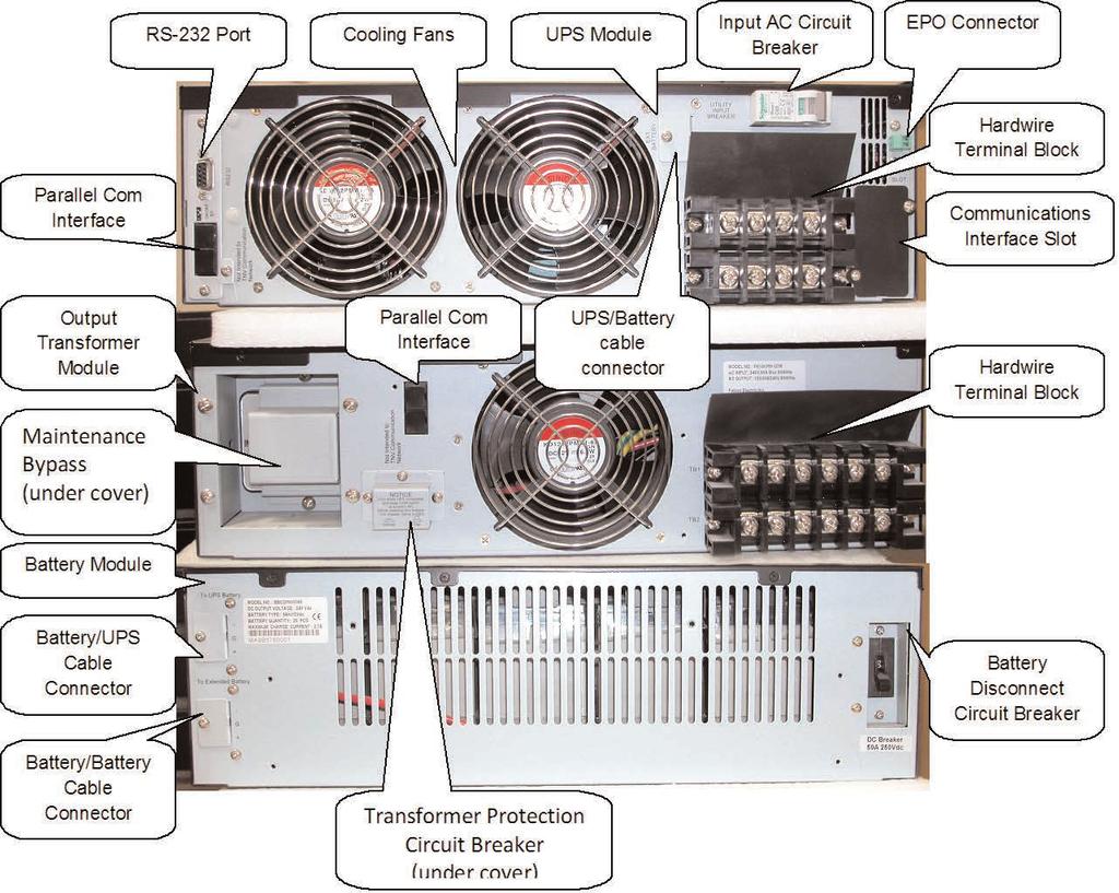
12 4.5 FN 3kVA to 6kVA Rackmount System Rear Panel Overview 4.6 FN 8kVA to 10kVA Rackmount System Rear Panel Overview 12


13 4.7 3 to 6kVA Output Transformer Module Hardwire Terminal Block Wiring Details to 6kVA UPS Module Hardwire Terminal Block Wiring Details 13


14 4.9 8 to 10kVA UPS Module Hardwire Terminal Block Wiring Details to 10kVA Output Transformer Module Hardwire Terminal Block Wiring Details 14
 Panel Master")
15 to 6kVA System Installation Wiring Diagram (single rackmount UPS system) to 6kVA System Installation Wiring Diagram (typical multiple parallel UPS units, Suggested UPS Output Panel & Circuit Breakers UPS Output Panel = Square D P/NQQ12L125G (1 each) Panel Master Circuit Breaker 120A = QQM110VH (1 Each) Individual UPS Circuit Breakers 3kVA -- 20A Square D P/N QQ220VH 4kVA to 6kVA -- 30A Square D P/N QQ230VH 8kVA -- 50A Square D P/N QQ250VH 10kVA -- 60A Square D P/N QQ260VH 4.13 UPS & Transformer Modules Communications Bus Cabling Use one UA88385 parallel communications bus cabling kit for each UPS to be connected to the system output transformer module or to paralleled UPS systems. Connect the supplied cables as shown below. Note the first and last connectors on the first and last UPS are connected using the longer of the supplied cables. Switch on the termination resistor dip switch next to the long cable. For the transformer module, daisy chain the cables from the UPS to the transformer module in a similar manner using the communications connectors located on the transformer module rear panel. 15

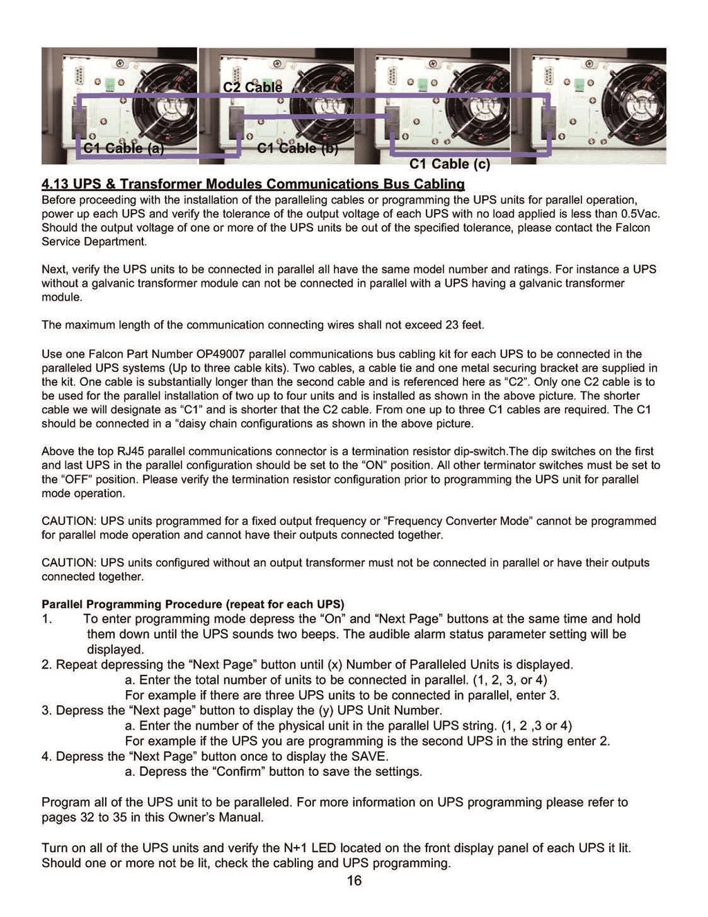
16

17 to 10kVA System Installation Wiring Diagram (typical rackmount UPS system) 17

18 Parallel Mode Installation and Configuration Whenever FN Series UPS units are connected in parallel with the parallel communications cabling installed, the communicaitons bus termination switched located to the right side of the cable connectors must be set as follows: When convifuring paralleled units, set the termination resistor switch to the on position for the first and last paralleled UPS only. IF two units are paralleled set the switch to on for units 1 & 2, for three units, set the swirches on for units 1 & 3. For four unit set switches on the units 1 & 4 to on. Never set the termination resistor switch to the on position for single unit installations. Primary N+1 UPS Setup Procedure 1. Connect UPS to utility source 208Vac or 240 Vac 2. Turn on CB1 and CB2 on rear panel and leave the unit in bypass mode (BPS) 3. Press and hold the ON and Next Page button simultaneously until the unit beeps twice and enters programming mode. 4. Using the Next Page button, scroll down to confirm the UPS unit address is d01 (Default setting) 5. Using the Next Page button, scroll down to the parallel configuration P01 (Default Setting, Non-Parallel) 6. Using the Change Setting button, change the configuration to P02 which enables parallel operation. 7. Using the Next Page button scroll down to Save then press the Enter button until it beeps. 8. The unit will then automatically exit the programming mode and will display Off on the front panel. 9. Shut off CB1 and CB2 Second, Third, Fourth N+1 UPS Setup Procedure 1. Connect UPS to utility source 208Vac or 240 Vac 2. Turn on CB1 and CB2 on rear panel and leave the unit in bypass mode (BPS) 3. Press and hold the ON and Next Page button simultaneously until the unit beeps twice and enters programming mode. 4. Using the Next Page button, scroll down to the UPS address setting. d01 (Default setting) 5. Using the Change Setting button, assign the UPS address to either d02, d03, or d04 depending on how many UPS are being connected in parallel. 6. Using the Next Page button, scroll down to the parallel configuration P01 (Default Setting, Non-Parallel) 7. Using the Change Setting button, change the configuration to P02 which enables parallel operation. 8. Using the Next Page button scroll down to Save then press the Enter button until it beeps. 9. The unit will then automatically exit the programming mode and will display Off on the front panel. 10. Shut off CB1 and CB2 11. Repeat steps 1 through 10 to set up the, third, and fourth UPS in a parallel string if necessary. 12. Set UPS Communication Bus Termination Resistor Switch to the ON position. See Table 1 for configuration. Table 1. # of UPS in Parallel Switch Setting 1 Off 2 1st and 2nd UPS ON 3 1st and 3rd UPS ON 4 1st and 4th UPS ON 13. Connect daisy chain (3076) bus cable to link up each UPS in parallel. See Fig Connect wrap around (3077) bus cable between the first and last UPS in the parallel string. See Fig Connect the UPS outputs together in parallel to load bank. See Manual for configuration 16. Connect the UPS Inputs together in parallel to utility source. See Manual for configuration 17. Turn on CB1 and CB2 18. Press and hold the ON button until it beeps. The unit will take a few minutes to switch to inverter mode. If the following set tings were not programmed correctly, the alarm will sound and will give and error code. (Er 27) 18


19 4.15 External Battery Charger Option Installation Wiring Detail (Typical UPS unit with optional FN6KBC-5A-2 5 Amp External Battery Charger Module FN6KBC-5A-2 Battery Charger Module Terminal Block Wiring Details Battery Charger Module/UPS System Wiring Diagram 19

20 5.0 DISPLAY & CONTROLS The pictures below outline the various control panel, LED and LCD functions and locations. 5.1 Control Button and LCD Locations 1. LCD Display 2. N+1 Status LED 3. Utility Status Indicator LED 4. Bypass Input Status LED 5. UPS On / Alarm Silence Control Button 6. Previous Page / Change Setting Button 7. Confirm Button 8. Next Page Button 9. UPS Off / Bypass Button 10. Function Button 11. Economy/Green Mode Status LED 12. UPS Alarm LED 5.2 Control Button Operation On/Alarm Silence Button Control Panel 1. When utility power is present and the UPS input circuit breakers are in the On position, depressing and holding this button for 5 seconds will turn on the UPS. 2. When utility power is not present or the UPS input circuit breaker is in the Off position, depressing and holding this button for 5 seconds will initiate a preliminary startup sequence. When Off or BPS is displayed on the LCD, depressing the On button again for 6 seconds will start up the UPS in battery mode (cold start). 3. When the UPS is in utility or battery mode, depressing this button will silence any audible alarms. Off/Bypass Button 1. When the UPS is operating in utility or battery mode, depressing and holding this button until an audible beep is sounded will leave the load powered in bypass mode. To completely shut down the UPS and connected load, press the Off/Bypass button until Off is displayed on the LCD, and then turn off the UPS and Bypass input circuit breakers. The UPS will shut down in about one minute. 2. When the LCD is in the Display Programmed Settings mode, depressing the Function Button will return the LCD to normal mode. The LCD display will also return to Normal Mode automatically after 30 seconds of button inactivity. Previous Page/Change Setting Button Function Button 1. When the UPS is operating in utility or battery mode, depressing the Function Button will switch the LCD to display the Programmed Parameter settings. When in this mode, depressing the Next Page button will display the next programmed parameter setting. Repeatedly depress the Next Page button to display all of the programmed parameter settings When the LCD display is in Normal Mode, repeated pressing of this button will sequence up through the input/output/battery parameters and readings will be displayed. 2. When in Programming Mode, pressing this button will change the selected parameter setting. The new setting will be displayed on the LCD Measurement display.
21 Next Page Button 1. When the LCD display is in Normal Mode, repeated pressing of this button will sequence down through the input/output/battery parameters and readings. 2. When the UPS is displaying OFF or BPS, depressing the Next Page and Function buttons at the same time will place the UPS into Programming Mode. Refer to the How to Change the Programmed Settings section of this manual for more details. 3. When in Programming Mode, repeated pressing of this button will sequentially select the various programmable parameters. Refer to page 27, How to Change the Programmed Settings section of this manual for more details. Confirm Button 1. When in Programming Mode and prompted on the LCD display to SAVE settings, pressing this button will save all changed parameters. 5.3 LED Display Modes Utility (AC Source 1) UPS Input Power Present LED (Green) -- Indicates utility power is present and the UPS input circuit breakers is turned on. If the utility voltage is out of tolerance the LED will turn off. Bypass (AC Source 2) Bypass Input Power Present LED (Green)-- Indicates bypass power is present and the Bypass circuit breaker is turned on. If bypass power is out of range, the LED will turn off. N+1 Mode Enabled (Green) - Indicates multiple UPS units are connected in parallel and have been properly configured and programmed for Parallel N+1 mode operation. Economy/Green Mode Enabled (Yellow) -- Indicates Economy/Green mode has been enabled. Alarm Condition Present (Red) -- Indicates the UPS in an alarm condition. 21


22 5.4 LCD Display Overview LCD Display 5.5 LCD Icon Descriptions Shown in Test Mode 1. Bypass input is out of tolerance, UPS failed to transfer to bypass, or bypass input is out of tolerance when the UPS is in Economy/Green Mode. 2. Utility loss or the utility input is out of tolerance. 3. UPS lost inverter output and transferred to bypass. 4. Battery voltage is out of tolerance, or defective batteries. 5. The UPS output is overloaded. 6. The UPS is presently in maintenance mode. 7. MIMIC Display showing Line, UPS, Battery and Load. When referenced in conjunction with arrows 8, 9 and 11, it defines the operational state of the UPS. They also indicate the source of the input/output/battery parameter readings displayed on the Measurement Display (12). 8, 9 & 11. MIMIC display and Measurement location indicators. 10. Battery and Low Battery Icons. The battery icon is displayed as part of the MIMIC display. In the event of a utility loss that depletes that battery charge, the Low Battery icon is displayed until the batteries have recharged to a reasonable level. In the event of a complete battery discharge, the low battery icon will be displayed along with an audible alarm. When the batteries have recharged to a reasonable level, the normal battery icon will be displayed. 12. Measurement Display. The Measurement display is used to show the input/output/battery readings, program mode settings, status and error codes. 5.6 Status and Error Code Descriptions OFF or BPS-- Displayed when the UPS is turned off with the Off button, EPO or remote shutdown. EPO -- When an optional EPO communications board is installed, EPO is displayed alternately with the OFF or BPS message, after an EPO signal has been applied to the EPO interface connector. After an EPO condition, the UPS input circuit breaker must be turned off and the Off button must be depressed twice for 5 seconds to reset the UPS prior to turning the UPS and Bypass input circuit breakers back on. 22
23 Er04 -- Er05 -- Er06 -- Er07 -- Er08 -- Er09 -- Er10 -- Er11 -- Er12 -- Er13 -- Er14 -- Er15 -- Er18 -- Er22 -- Er24 -- Er26 -- Er28 -- Er29 -- Er** -- Error code 04 indicates the UPS inverter has malfunctioned. Contact Falcon Service. Error code 05 indicates the UPS batteries are weak or dead and must be replaced. Call Falcon Service upon receiving the message for further instructions. Error code 06 indicates the UPS output has a short circuit connected to it. Remove the connected equipment load from the UPS output and restart the UPS. If the shorted output condition is corrected, determine the location of the shorted wiring or equipment. EPO Mode. DC Bus high voltage level out of specification. Contact Falcon Service. DC Bus low voltage level out of specification. Contact Falcon Service. Error code 10 indicates the UPS inverter has encountered an over-current condition. This could indicate the connected equipment exceeds the output rating of the UPS. Disconnect some of the connected equipment in an attempt to correct the condition. Error code 11 indicates the UPS is in an over-temperature condition. Verify the ambient operating temperature is not too high. Verify the UPS cooling fan operation. Error code 12 indicates the UPS output is overloaded, similar to error code 10. This could indicate the connected equipment exceeds the output rating of the UPS. Disconnect some of the connected equipment in an attempt to correct the condition. Battery charger malfunction. Contact Falcon Service. Cooling fan failure. Contact Falcon Service. Maintenance bypass initiated improperly. Refer to page 31, Maintenance Bypass section. Internal software error, UPS programming reset to default values. Static bypass malfunction. Contact Falcon Service. Fixed 50 or 60Hz output mode programmed without turning off the bypass input circuit breaker Should a fixed 50 or 60Hz output be desired, turn the bypass input circuit breaker off. To clear error code 24, startup the UPS with the Bypass input circuit breaker turned off. PFC over-current condition. Verify the UPS output is or has been overloaded. The UPS output has experienced a 120% overload in bypass for over 2 minutes. Bypass has been shutdown. The battery charger is overcharging the batteries. Contact Falcon Service. Other error code, consult with Falcon Service. 23


24 6.0 OPERATION The following sections outline the operation and programming of the FN -2TXI UPS models. Please read and understand them completely prior to connecting any equipment to the UPS output. 6.1 How to start up the UPS with utility power present 1. Verify the UPS input wiring is correct and connected to a live circuit. 2. Turn on the UPS and Bypass input circuit breakers located on the UPS rear panel, and the following LCD Display will be displayed. The UPS output will be immediately turned on, with the UPS in bypass mode. Display A is an LCD test display and is shown for about 3 seconds after the input circuit breaker is turned on. Next, display B is shown (OFF or BPS displayed). The UPS is OFF with the load supported by the bypass output. The UPS will remain in this state until the On button is depressed. When the UPS is turned off using the Off button, it will return to this state until the input circuit breaker is turned off. 3. Depress the On button for 3 seconds until two audible beeps are sounded. 4. The UPS fans will turn on and the following LCD display will be shown: The UPS will sound two short beeps continuously until the following is displayed. NOTE: Always allow the UPS to charge its batteries for 8 hours prior to use. 5. The UPS will now sequence up to on-line mode and display the following: Note the MIMIC portion of the display with the arrow under the line and the input voltage is displayed. The UPS initiates a self-test. Go to the next page. 24
25 If the UPS passes the self-test, OK is displayed. If the UPS fails the self-test, FAIL is displayed alternately with an error code. Please note the error code and contact Falcon Service. The UPS is now turned on and in on-line inverter mode. Using an AC volt meter, verify the UPS input voltage measurement. 25
26 6.2 How to start up the UPS without utility power present (Cold Start) 1. Press the On button for 6 seconds to awaken the UPS. The UPS will beep twice and display G below. Immediately upon G being displayed, press the On button for another 6 seconds. The UPS will beep twice again and sequence through H and I. After depressing the On button for 6 seconds the first time, the UPS will beep twice and OFF or BPS will be displayed. After depressing the On button the second time for 6 seconds, the UPS will display input voltage H and I. The UPS output voltage will be present and the UPS will continue to run on battery until the batteries are discharged or the Off button is pressed for 3 seconds. 6.3 How to turn off the UPS inverter and place the UPS into bypass mode 1. While the UPS is operating in utility, inverter or battery mode, depress the Off button until the UPS sounds two audible beeps. The UPS will switch to static bypass and turn off the inverter. The LCD will display OFF or BPS. The connected load will now be powered directly from the utility source. The UPS will continue to operate in bypass mode until: a. The On button is depressed for three seconds, which will return the UPS to normal inverter mode operation. b. The UPS and Bypass Input circuit breakers are turned off, which will shut down the UPS and the connected load completely. 6.4 How to completely shutdown the UPS 1. While the UPS is operating in utility, inverter or battery mode, depress the Off button until the UPS sounds two audible beeps. The UPS will switch to static bypass and turn off the inverter. The LCD will display OFF or BPS. 2. Turn off the UPS and Bypass input circuit breakers, which will shutdown the UPS and the connected load completely. Note, the UPS may continue to run for 30 seconds to one minute prior to turning off. 26

27 6.5 How to display readings 1. The bypass input voltage is displayed immediately after the UPS and Bypass circuit breakers are turned on and has sequenced up to inverter mode as shown in I1. Depressing the Next Page button will change to display the utility frequency as shown in J below. The b denotes the reading is for the bypass. The arrow under the LINE indicates the reading is for the bypass input voltage. Depress the Next Page button. The r denotes the reading is for utility. The arrow under the LINE indicates the reading is for the utility frequency. Depress the Next Page button. The b denotes the reading is for the bypass. Depress the Next Page button. The arrow under the LOAD indicates the reading is for the UPS output voltage. Depress the Next Page button. The arrow under the LOAD indicates the reading is for the UPS output frequency. Depress the Next Page button. The arrow under the LOAD indicates the reading is for the UPS output and indicates the percentage of output load connected to the UPS. 27
28 Depress the Next Page button. The arrow next to the battery icon indicates the reading is for the battery voltage. Depress the Next Page button. The degree C symbol indicates the reading is for the internal UPS temperature. Depressing the Next Page button again will return the display to reading I1. 28
29 6.6 How to Display Programmed Settings 1. The UPS must be turned on and operating in on-line inverter mode prior to attempting to read the programmed settings. 2. Depress the Function button and the following first function parameter will be displayed: The first function status displayed will be the audible alarm buzzer status. It is shown here to be turned on. If the Previous Page/Change Setting button is pressed, the audible alarm will be turned off. Depressing the button again will turn the alarm back on. Depress the Next Page button. Next, the self-test status is displayed. Here the self-test is shown to be in the Test Not On state. If the Previous Page/Change Setting button is pressed, a UPS self-test will be initiated and the following displays will be shown. Depress the Next Page button. Go to the next page. 29
30 Note: The following functions are a continuation from the previous page. These functions can only be displayed and must have their settings changed using another programming method referenced later in the manual. As the other programming method requires turning the UPS off to perform, they are accessible here as a convenient reference while the UPS is in normal online operation. The next parameter displayed shows the bypass input voltage acceptable window setting. The voltage window can be set to Lo ( Vac) or Hi ( Vac), which is shown below. Depress the Next Page button. The next parameter displayed shows acceptable input frequency window. The window can be set to +/-3Hz (shown), or +/-1Hz (not shown). Depress the Next Page button. The next parameter display is the inverter output voltage setting. The inverter output voltage can be set to 200Vac (not shown), 220Vac (shown), 230Vac (not shown) or 240Vac (not shown). Depress the Next Page button. The following V1, V2, V3 and V4 show the operational status setting of the UPS. This function may be set to one of four modes. Normal indicates none of the other modes are set. Economy/Green Mode: Indicates the UPS will automatically transfer to bypass mode to save energy, one minute after the output load drops below 10% of the UPS output rating. 30
31 Fixed or constant frequency output mode: In normal mode the UPS output frequency will automatically be set to the utility frequency and is synchronized with that frequency. When set to cf50hz mode, the UPS inverter output frequency will always be 50Hz. When set to cf60hz mode, the UPS inverter output frequency will always be 60Hz. Setting the UPS to a fixed or constant output frequency should be done when the input source is a generator. Depress the Next Page button. The next parameter displayed shows the inverter output voltage adjustment. The adjustment can be set to 0% (shown), +1%, -1%, +2%, -2%, +3%or -3% (not shown). Depress the Next Page button. X The next parameter displayed shows the UPS unit address. If only one UPS is being used, the address should be set to d0 as shown. If multiple parallel UPS units are connected in a parallel configuration of 6, 12, 18 or 24kVA, or 6, 12, 18kVA N+1 operation, the units would be addressed d0, d1, d2 and d3. See the parallel mode configuration section on page 30 of this manual for more details. Depress the Next Page button. The next parameter displayed shows the UPS position when it is used in a parallel configuration. The positions are 01, 02, 03, or If only one UPS is being configured, the position should be set to 01 as shown.
32 6.7 How to Change the Programmed Settings Note: The UPS must be placed into Off / Bypass mode prior to attempting to change the following parameter settings. 1. To enter programming mode depress the On and Next Page buttons at the same time and hold them down until the UPS sounds two beeps. The audible alarm status parameter setting will be displayed. The audible alarm parameter settings cannot be set in this programming mode. Refer to section 6 of this manual for setup instructions. Depress the Next Page button. Self-test parameter settings cannot be set in this programming mode. Refer to section 6 of this manual for setup instructions. Depress the Next Page button and go to the next page. 32
33 The next parameter displayed shows the bypass input voltage acceptable window setting. The voltage window can be set to Lo ( Vac) or Hi ( Vac), which is shown below. To change the settings, depress the Previous Page/Change Setting button. To change to the alternate setting, press the button again. All setting changes will be saved when prompted at the end of the parameter sequence. Depress the Next Page button. The next parameter displayed shows the acceptable input frequency window. The window can be set to +/-3Hz (shown), or +/-1Hz (not shown). To change the settings, depress the Previous Page/Change Setting button. To change to the alternate setting, press the button again. All setting changes will be saved when prompted at the end of the parameter sequence. Depress the Next Page button. The next parameter display is the inverter output voltage setting. The inverter output voltage can be set to 200Vac (not shown), 220Vac (shown), 230Vac (not shown) or 240Vac (not shown). To change the settings, depress the Previous Page/Change Setting button. To change to another voltage setting, repeat pressing the button until the desired voltage is displayed. All setting changes will be saved when prompted at the end of the parameter sequence. Depress the Next Page button and go to the next page. 33
34 The following V1, V2, V3 and V4 show the operational status setting of the UPS. This function may be set to one of four modes. Normal : which indicates none of the other modes are set. The Economy/Green Mode: indicates the UPS will automatically transfer to bypass mode to save energy, should the output load drop below 10% of the UPS output rating. Fixed or constant frequency output mode: In normal mode the UPS output frequency will automatically be set to the utility frequency and is synchronized with that frequency. When set to cf50hz mode, the UPS inverter output frequency will always be 50Hz. When set to cf60hz mode, the UPS inverter output frequency will always be 60Hz. Setting the UPS to a fixed or constant output frequency should be done when the input source is a generator. To change between these settings, depress the Previous Page/Change Setting button. Repeat pressing the button until the desired mode setting is displayed. All setting changes will be saved when prompted at the end of the parameter sequence. Depress the Next Page button. The next parameter displayed shows the inverter output voltage adjustment. The adjustment can be set to 0% (shown), +1%, -1%, +2%, -2%, +3%or -3% (not shown). 34 To change between these settings, depress the Previous Page/Change Setting button. Repeat pressing the button until the desired mode setting is displayed. All setting changes will be saved when prompted at the end of the parameter sequence.
35 X The next parameter displayed shows the UPS unit address. If only one UPS is being used, the address should be set to d0 as shown. If multiple parallel UPS units are connected on a parallel configuration of 6, 12, 18 or 24kVA, or 6, 12, 18kVA N+1 operation, the units would be addressed d0, d1, d2 and d3. See the parallel mode configuration section of this manual for more details. To change between these settings, depress the Previous Page/Change Setting button. Repeat pressing the button until the desired address setting is displayed. All setting changes will be saved when prompted at the end of the parameter setup. Depress the Next Page button. The next parameter displayed shows the UPS position when used in a parallel configuration. The positions are 01, 02, 03, or 04. If only one UPS is being configured, the position should be set to 01 as shown. To change between these settings, depress the Previous Page/Change Setting button. Repeat pressing the button until the desired UPS position setting is displayed. All setting changes will be saved when prompted at the end of the parameter setup. Depress the Next Page button. At the end of the parameter setup mode, you will be prompted to save the settings. To save the settings press the Confirm button. If you do not wish to save the settings, press the Off / Bypass button for five seconds. The LCD will display OFF to indicate the settings are not saved. IMPORTANT:The UPS must be switched to maintenance bypass mode, shut down and restarted after entering the programming mode. 35
36 6.8 How to Use the Maintenance Bypass Switch Located on the Rear Panel IMPORTANT: Improper use of the internal Maintenance Bypass Switch will void the equipment warranty. The following instructions must be followed whenever this switch is used. 1. Press the Off/Bypass button for 5 seconds to place the UPS into bypass mode. 2. On the rear of the transformer module, remove the two phillips screws securing the upper and lower sides of the maintenance bypass security cover plate. 3. On the rear of the transformer module, turn the Maintenance Bypass Switch to Bypass. The maintenance bypass icon will be displayed on the LCD display. 4. The output transformer is now in maintenance bypass mode. 5. To return to normal UPS mode operation, switch the Maintenance Bypass Switch to INV. Replace the switch cover plate and secure it with the screws previously removed. 6. Press the On button on the UPS module to return the UPS to normal inverter operation. 36
37 7.0 COMMUNICATIONS All FN models are provided with the following communication ports: RS-232 port with standard DB-9F serial port connector located on the UPS module rear panel. Two advanced communications option slots are provided on the rear panel of the UPS module. Unless an advanced communications option board has been previously purchased and installed, the port will be covered with a small cover plate. This plate will be secured with (2) screws. CAUTION: NEVER INSTALL OPTION CARDS THAT HAVE NOT BEEN SUPPLIED BY FALCON ELECTRIC, OR ARE FOR ANOTHER FALCON MODEL, WITHOUT CONSULTING WITH FALCON SERVICE. MOST SG SERIES COMMUNICATIONS BOARDS WILL NOT WORK IN FN SERIES MODELS. ONLY USE OPTION BOARDS THAT ARE SPECIFIED FOR FN 3, 5 & 6kVA MODELS. 7.1 Advanced Communications Option Cards Available: a. USHA TYPE SNMP/HTTP Agent Board b. Dry Contact with EPO Interface Board (P/N UA88383) c. USB & EPO Interface Board (P/N UA88382) d. RS485 & EPO Interface Board (P/N UA88381) e. Second RS-232 Interface Card (P/N UA88380) CAUTION: The internal USHA SNMP/HTTP AGENT device must be installed into the Advanced Communications Option Slot specified in this manual. Do not attempt to install it in the contact closure option card slot. The RS-232 port and UPSilon software may not be used when the USHA card is installed. 7.2 RS-232 Port The UPS is equipped with (1) RS-232 port located on the UPS module rear panel. A standard RS-232C interface cable is provided to allow for the connection of the UPS to another RS-232 port found on most computers. When an RS-232 cable has been connected, and the supplied UPSilon computer shutdown and management software has been properly installed on the connected computer, a high level of UPS management and protection against lost or corrupted files is in effect. Please follow the installation and setup instructions supplied on the UPSilon software CD. The UPSilon users manual is also located on the UPSilon CD supplied with this unit. UPSilon supports most popular operating systems. Should you have special UNIX requirements, please contact Falcon Sales for information and pricing of UPSilon for UNIX. The UPS & PC Computer DB-9 pin designations are as follows: 37
 A two-pin REPO connector (green connector) is located on the UPS module rear panel.")
38 The supplied Falcon RS-232 interface cable pin designations are as follows: UPS Side RS-232C Interface Computer Side The computer RS-232 Port settings should be set to the following: 7.3 Optional Remote Emergency Power Off (REPO) A two-pin REPO connector (green connector) is located on the UPS module rear panel. The connector is shipped with no jumper wire installed, and is a normally open interface requiring a CLOSED EPO connection to initiate EPO UPS shutdown. Upon receiving the remote EPO switch contact closure, the UPS will immediately turn off it s inverter and bypass outputs, in addition to placing the UPS into an OFF state and sounding an audible alarm. OFF and EPO will be alternately displayed on the LCD panel. After removal of the EPO contact closure, the UPS must be completely shut down and restarted to clear the EPO condition. 7.4 Optional Communications Interface Board Details UA88380 Second RS-232 Interface Option Board This communications board supports the connection of a second RS-232 DB-9 connection to the UPS, in addition to providing (1) two-pin EPO interface connector. The DB-9 pinout is identical to the standard DB-9 RS-232 interface found on the UPS rear panel. UA88381 RS-485 Interface Option Board This communications board has (1) RS485 standard interface (CN2), in addition to providing (1) two-pin EPO interface connector (CN1), and (1) two-pin remote power connector (CN3). Pin 1 - Ground Pin 2 - A/Data+ Pin 3 - B.Data- Pin 1 - AC+ Pin 2 - AC- CN CN3 1 2 Pin 1 - REPO 1 Pin 2 - REPO 2 CN
 Pin 2 - D- Pin 3 - D+ Pin 4 - Ground Pin 1 - REPO 1 Pin 2 - REPO2 CN1 1 2 UA88383 Dry Contact Interface Option Card This card provides dry contact closure signals for UPS on")


39 UA88382 USB Interface Option Card This option card supports the connection of (1) USB interface cable for use with UPSilon remote monitoring, management and unattended O/S shutdown software Pin 1 - VCC (+5V) Pin 2 - D- Pin 3 - D+ Pin 4 - Ground Pin 1 - REPO 1 Pin 2 - REPO2 CN1 1 2 UA88383 Dry Contact Interface Option Card This card provides dry contact closure signals for UPS on bypass, utility normal, inverter on, low battery, abnormal battery, UPS summary alarm. It also provides EPO and remote UPS shutdown capability USHA SNMP/HTTP Agent Option Card Pin 1 - UPS on Bypass Pin 2 - Utility Abnormal Pin 3 - Utility Normal Pin 4 - Inverter On Pin 5 - Low Battery Pin 6 - Abnormal Battery Pin 7 - UPS Summary Alarm Pin 8 - Common Pin 9 - Shutdown UPS (+) signal Pin 10 - Shutdown UPS (-) signal Pins 9 & 10 apply 6-25Vdc for 5 seconds to activate shutdown. Now you can monitor and manage your Falcon Electric FN Series UPS across an Ethernet LAN, WAN, Enterprise Network or via the World Wide Web. With our Universal SNMP/HTTP Agent board (USHA), remote management is easy using a standard web browser or Network Management Software (NMS). Remote SNMP/HTTP UPS management is a simple matter of inserting our USHA board into the designated option port provided on the rear panel of every FN Series UPS. The USHA board is supplied with a SNMP UPS MIB II compliant "snap-in" Management Information Base (MIB). The MIB is compatible with HP OpenView and other Network Management Software (NMS). Remote server and computer shutdown client software is also provided on the CD that is shipped with this option. The software supports the shutdown of multiple servers or computers in-band across any Ethernet LAN. The client software may be installed on as many systems as required and supports most MS Windows and server platforms, in addition to LINUX. 39
 Yuasa 12V, 7AH or equivalent, sealed, VRLA, maintenance-free, lead-acid batteries.")

40 8.0 MAINTENANCE The FN Series UPS requires very little maintenance. The batteries are located inside the battery module and consist of (20) Yuasa 12V, 7AH or equivalent, sealed, VRLA, maintenance-free, lead-acid batteries. Batteries must be kept recharged to prevent excessive self-discharging, which may result in their premature failure. When connected to the battery module, the UPS will continuously recharge the batteries when plugged in and turned on. When not in use, batteries must be recharged every 6 months to keep your warranty valid. 1. The UPS and Battery Care Keep the area around the UPS clean and dust free. If the area around the UPS becomes very dusty, clean it with a vacuum cleaner. To assure the full 3-5 year battery life, keep the UPS battery module at an ambient temperature of 77ºF (25ºC). Other than replacement at three to five years of service, no other battery maintenance is required. 2. Storing the UPS and Batteries When storing the UPS for any amount of time, it is recommended to connect the battery module and turn on the UPS for at least 24 hours, every four to six months to ensure full recharging of the batteries. This will prevent excessive battery self-discharge. 3. When to Replace Batteries We suggest the battery pack(s) be replaced every 3-5 years for FN units that are operated and maintained in a 77ºF (25ºC) environment. Higher temperature operating environments will decrease the battery life. Typically, if the UPS is installed in a 104ºF (40ºC) or above operating environment, the batteries will need to be replaced once a year. In order to assure the performance of the FN Series UPS, check the battery every two to three months by performing a UPS self-test. If at any time the UPS LCD panel displays the weak or defective battery icon or error code, the batteries need replacing. Contact the Falcon Electric Service Department to order replacement batteries. 4. Battery Replacement Battery replacement inside the battery module must be performed by a qualified service technician. Contact Falcon service when battery replacement is required. NOTE! NEVER ATTEMPT TO REPLACE THE BATTERY PACKS WHILE THE UPS IS IN BATTERY MODE. 40
 like kva FN model UPS units may be connected to their respective transformer modules and/or in parallel, in single UPS increments, to provide a single 3-24kVA UPS output a true N+1")
41 9.0 PARALLEL MODE OPERATION 9.1 How to configure FN rackmount models for transformer module, parallel or N+1 mode operation. Up to (4) like kva FN model UPS units may be connected to their respective transformer modules and/or in parallel, in single UPS increments, to provide a single 3-24kVA UPS output a true N+1 redundant output. This is accomplished by connecting each UPS to be paralleled, wired to a single utility source rated for the combined UPS load. The UPS outputs should be connected together. A licensed electrician can provide the hardwire output connections and circuit. Each individual UPS output must have a branch rated circuit breaker as specified prior, installed between the UPS output and load. FN models have two special bus connectors located on the UPS rear panel that supports interconnection of the transformer module and/or paralleled UPS units. (1) parallel UPS interface kit must be purchased from Falcon for each UPS to be paralleled. The cable kit is shipped with each transformer module inside the shipping container. The interface kit contains (1) daisy chain bus cable (3076), (1) wrap around bus cable (3077), detailed installation instructions and assorted hardware. The Falcon part number for the kit is UA How to connect the Battery Module to the UPS module. 1. Open the battery connector cover plate from the UPS module rear panel and connect the supplied red, black and green battery cable connectors to the respectively colored mating connectors on the UPS module. 2. On the battery module rear panel verify the battery circuit breaker is in the off position. Next, open the top battery connector cover plate. Connect the red, black and green connectors on the opposite side of the battery cable to the respectively colored mating connectors on the battery module. Turn on the battery module circuit breaker. The UPS may now be powered up. 3. To add a more battery modules, remove the lower cover plate on the first module and connect a the supplied battery cables to this connector on the previous battery module. For more details, contact Falcon Sales or Support Engineering. 41
Table of contents. 1. Introduction
 2 Year Warranty Table of contents 1. Introduction 1-1. Transportation 1-2. Preliminary steps 1-3. Initial setup 1-4. Important safety instructions 1-5. Maintenance, service and faults 2. Operation 2.1
User Manual. Network Pro Series Tower and Rack-Mount Convertible UPS. Table of Contents 1000/1500/2200/3000
 Table of Contents Network Pro Series Tower and Rack-Mount Convertible UPS User Manual 1 Introduction ------------------------------------------------------------------------------------2 2 IMPORTANT SAFETY
Imperial Series. Model IMP-425/525/625/825/1000AP IMD-425/525/625/825/1000AP IMP-1025/1200/1500/2000AP IMD-1025/1200/1500/2000AP
 Service Manual Imperial Series Model IMP-425/525/625/825/1000AP IMD-425/525/625/825/1000AP IMP-1025/1200/1500/2000AP IMD-1025/1200/1500/2000AP Contents of Service Manual 1. Safety Precautions ------------------------------------------------------------------
MODELS MB1K-1, MB1K-2 MB2K-1, MB2K-2 MB3K-1, MB3K-2
 FALCON ELECTRIC INC. OWNER S MANUAL SG Series Maintenance Bypass Option 1KVA 3KVA MODELS MB1K-1, MB1K-2 MB2K-1, MB2K-2 MB3K-1, MB3K-2 OM48030 Rev. B 01/17/03 FALCON Electric Inc., 5106 Azusa Canyon Road,
XSTi Standby UPS. 400VA, 600VA, 800VA Models. User & Installation Manual
 XSTi Standby UPS 400VA, 600VA, 800VA Models User & Installation Manual www.xpcc.com 2015. All rights reserved. (Rev 12/14/15) Table of Contents Package Contents... 3 Product Introduction... 3 Product Overview...
C60 Standby UPS. 800VA Models. User & Installation Manual Xtreme Power Conversion Corporation. All rights reserved.
 For more information, visit www.247technology.com/on-line-ups/c60-standby-ups C60 Standby UPS 800VA Models User & Installation Manual 2015. All rights reserved. (Rev 6/23/15) Table of Contents Package
Minuteman Series. User's Manual
 Minuteman Series User's Manual CONTENTS PAGE 1. Introduction..1 2. Receiving Inspection. 1 3. Warranty Registration.1 4. Safety Instruction.1 5. Selection of UPS Location.2 6. Use of External Battery Packs
J60 Lithium Ion UPS 350VA Model User & Installation Manual Xtreme Power Conversion Corporation. All rights reserved.
 J60 Lithium Ion UPS 350VA Model User & Installation Manual www.xpcc.com 2018. All rights reserved. (Rev 5/24/18) Table of Contents Package Contents...3 Product Introduction...3 Product Overview...3 Installation
The power behind competitiveness. Delta UPS - Modulon Family. DPH Series, Three Phase kw. User Manual.
 The power behind competitiveness Delta UPS - Modulon Family DPH Series, Three Phase 25-150 kw User Manual www.deltapowersolutions.com Save This Manual This manual contains important instructions and warnings
Daker DK kva. Parallel installation quick start. Part. LE08927AA-09/15-01 GF
 Daker DK 4.5-10 kva Parallel installation quick start Part. LE08927AA-09/15-01 GF Daker DK 4.5-10 kva UK ENGLISH 3 2 Daker DK 4.5-10 kva Index Introduction 2 1 Important Safety Instructions 2 2 Parallel
HotSwap MBP Maintenance Bypass
 ENGLISH HotSwap MBP Maintenance Bypass MBP6K208 MBPK208 Installation and user manual Copyright 202 EATON All rights reserved. Service and suort: Call your local service representative SAFETY INSTRUCTIONS
Galaxy 300. Operation 05/
 Galaxy 300 60 80 kva Operation 05/2016 www.schneider-electric.com Legal Information The Schneider Electric brand and any registered trademarks of Schneider Electric Industries SAS referred to in this guide
The power behind competitiveness. Delta UPS - Modulon Family. DPH Series, Three Phase kva. User Manual.
 The power behind competitiveness Delta UPS - Modulon Family DPH Series, Three Phase 200-500 kva User Manual www.deltapowersolutions.com Save This Manual This manual contains important instructions and
Maintenance Bypass Breaker Cabinet Series Configuration 5. Installation and Operation Manual
 Maintenance Bypass Breaker Cabinet 90881 Series Configuration 5 Installation and Operation Manual 03/13/2012 2 755-00084-C5 R03 Copyright 2012 C&C Power, Inc. All rights reserved. C&C Power, Inc. 395 Mission
EPS 7000 and EPS 8000
 EPS 7000 and EPS 8000 Single and Parallel Operation 09/2015 www.schneider-electric.com Legal Information The Schneider Electric brand and any registered trademarks of Schneider Electric Industries SAS
Delta UPS - Ultron Family. HPH Series, Three Phase 60/80/100/120 kva. User Manual. The power behind competitiveness EPO
 EPO NORMAL BATTERY BYPASS FAULT ESC ON OFF The power behind competitiveness Delta UPS - Ultron Family HPH Series, Three Phase 60/80/100/120 kva User Manual www.deltapowersolutions.com Save This Manual
Galaxy 300 and Galaxy 300i
 Galaxy 300 and Galaxy 300i 10-40 kva 380/400/415 V Operation 07/2016 www.schneider-electric.com Legal Information The Schneider Electric brand and any registered trademarks of Schneider Electric Industries
Installation and Operation Manual
 Installation and Operation Manual Maintenance Bypass Panel Model: SU2030KMBP Tripp Lite follows a policy of continuous improvement. Product specifications are subject to change without notice. 1111 West
The power behind competitiveness. Delta UPS - Amplon Family. RT Series, Single Phase 5/ 6/ 10 kva. User Manual.
 The power behind competitiveness Delta UPS - Amplon Family RT Series, Single Phase 5/ 6/ 10 kva User Manual www.deltapowersolutions.com Save This Manual This manual contains important instructions and
LIEBERT Nfinity UPS. GUIDE SPECIFICATIONS for a 4 to 16 KVA (208/120V or 240/120V) Single - Phase Uninterruptible Power Supply System 1.
 Single - Phase Uninterruptible Power Supply System 1.") LIEBERT Nfinity UPS GUIDE SPECIFICATIONS for a 4 to 16 KVA (208/120V or 240/120V) Single - Phase Uninterruptible Power Supply System 1.1 SUMMARY 1.0 GENERAL This specification describes the Nfinity UPS,
LIEBERT Nfinity UPS GUIDE SPECIFICATIONS for a 4 to 16 KVA (208/120V or 240/120V) Single - Phase Uninterruptible Power Supply System 1.1 SUMMARY 1.0 GENERAL This specification describes the Nfinity UPS,
DPS. Save This Manual
 DPS Save This Manual This manual contains important instructions and warnings that you should follow during the installation, operation, storage and maintenance of this product. Failure to heed these instructions
Maintenance Bypass Breaker Cabinet Series Configuration 2. Installation and Operation Manual
 Maintenance Bypass Breaker Cabinet 90881 Series Configuration 2 Installation and Operation Manual 03/13/2012 2 755-00084-C2 R03 Copyright 2012 C&C Power, Inc. All rights reserved. C&C Power, Inc. 395 Mission
Delta UPS - Ultron Family. HPH Series, Three Phase 60/80/100/120 kva. User Manual. The power behind competitiveness EPO
 EPO NORMAL BATTERY BYPASS FAULT ESC ON OFF The power behind competitiveness Delta UPS - Ultron Family HPH Series, Three Phase 60/80/100/120 kva User Manual www.deltapowersolutions.com Save This Manual
kva single and parallel UPS Systems User s and Installation Manual
 80-130 kva single and parallel UPS Systems User s and Installation Manual 80-130 kva single and parallel UPS Systems CONTENTS 1. Introduction... 5 2. System description... 5 2.1 General description...
XBDM-HW63. 63A Model. User & Installation Manual Xtreme Power Conversion Corporation. All rights reserved.
 XBDM-HW63 63A Model User & Installation Manual www.xpcc.com 2016. All rights reserved. (Rev 3/02/16) Table of Contents Introduction...3 Product Overview... 3 Installation and Operation...4 Inspection...4
APC by Schneider Electric Smart-UPS VT Uninterruptible Power Supply Guide Specifications kva Three-Phase, 208 Volts, 60 Hertz Solution
 APC by Schneider Electric Smart-UPS VT Uninterruptible Power Supply Guide Specifications 10-30 kva Three-Phase, 208 Volts, 60 Hertz Solution THIS GUIDE SPECIFICATION IS WRITTEN IN ACCORDANCE WITH THE CONSTRUCTION
Equipment Specifications Low Voltage. Active Harmonic Filter
 Equipment Specifications Low Voltage Active Harmonic Filter 1.0 General Description This section contains the design standards, general equipment type and configuration, components, product description,
S70 Line Interactive Tower UPS
 S70 Line Interactive Tower UPS 500VA, 700VA, 1000VA, 1500VA, 2000VA Models User & Installation Manual www.xpcc.com 2014. All rights reserved. (Rev 8/13/14) Table of Contents Package Contents...3 Product
MGE TM Galaxy TM 6000: Specification guide
 MGE TM Galaxy TM 6000: Specification guide Parallel UPS, 250 to 3000 kva* * Power rating for an N+1 configuration. Contents 1 - UPS definition... D-3 1.1 - Purpose... D-3 1.2 - Brief description... D-3
Replacing the Billboard UPS
 Replacing the Billboard UPS (PN 1109502801SP) The billboard UPS (Uninterruptible Power Supply) is a 1500VA (Volt Amp) rack mounted intelligent UPS that prevents data loss, downtime, and equipment damage
APC by Schneider Electric MGE GALAXY 5500 Uninterruptible Power Supply Guide Specifications 20 kva to 120 kva Parallel UPS, three-phase
 APC by Schneider Electric MGE GALAXY 5500 Uninterruptible Power Supply Guide Specifications 20 kva to 120 kva Parallel UPS, three-phase THIS GUIDE SPECIFICATION IS WRITTEN IN ACCORDANCE WITH THE CONSTRUCTION
MGE Galaxy /50/60/80/100/130 kva. The recommended power protection for all critical applications
 MGE Galaxy 5000 40/50/60/80/100/130 kva The recommended power protection for all critical applications 40-130 kva state-of-the-art threephase power protection designed to meet a wide range of requirements
Truly Modular UPS. SCU CMS Series Modular UPS
 SCU CMS Series Modular UPS Truly Modular UPS Choice of UPS Module (10kVA, 25kVA, 50kVA) result in Rational Redundancy Modular, hot-swappable, field-replaceable STS, Monitor, UPS module Scalable from 10kVA
EPS /625/750/800/1,000/1,100 kva Performance power protection for critical applications. schneider-electric.com
 EPS 8000 555/625/750/800/1,000/1,100 kva Performance power protection for critical applications schneider-electric.com 2 schneider-electric.com 555 1,100 kva robust three-phase power protection with adaptability
APC by Schneider Electric MGE GALAXY 7000 Uninterruptible Power Supply Guide Specifications 160 kva to 500 kva Single UPS 3-phase system
 APC by Schneider Electric MGE GALAXY 7000 Uninterruptible Power Supply Guide Specifications 160 kva to 500 kva Single UPS 3-phase system THIS GUIDE SPECIFICATION IS WRITTEN IN ACCORDANCE WITH THE CONSTRUCTION
UNINTERRUPTIBLE POWER SUPPLY MODEL 9900C MUITI MODULE SYSTEM SPECIFICATIONS. Copyright 2015, Mitsubishi Electric Power Products, Inc. U-ENS00064 Rev.
 UNINTERRUPTIBLE POWER SUPPLY MODEL 9900C MUITI MODULE SYSTEM SPECIFICATIONS TABLE OF CONTENTS PART 1 GENERAL... 2 1.1 SUMMARY... 2 1.2 STANDARD... 2 1.3 MMS SYSTEM DESCRIPTION... 2 1.3.1 UPS Components...
APC by Schneider Electric APC SYMMETRA MW 400 kw to 1600 kw Multi-Module Uninterruptible Power Supply
 APC by Schneider Electric APC SYMMETRA MW 400 kw to 1600 kw Multi-Module Uninterruptible Power Supply THIS GUIDE SPECIFICATION IS WRITTEN IN ACCORDANCE WITH THE CONSTRUCTION SPECIFICATIONS INSTITUTE (CSI)
PD6770 VANTAGEVIEW LOOP-POWERED PROCESS METER
 PD6770 VANTAGEVIEW LOOP-POWERED PROCESS METER 4-20 ma input 1 V drop (4 V with Backlight) 3½ Digits LCD, 1" High Loop-Powered Backlight Option HART Protocol Transparent Plastic NEMA 4X, IP65 Enclosure
UNINTERRUPTIBLE POWER SUPPLY MODEL 9800AE MULTI MODULE SYSTEM SPECIFICATIONS
 UNINTERRUPTIBLE POWER SUPPLY MODEL 9800AE MULTI MODULE SYSTEM SPECIFICATIONS TABLE OF CONTENTS 1. GENERAL...2 1.1. SUMMARY...2 1.2. STANDARD...2 1.3. UPS MMS SYSTEM DESCRIPTION...2 1.3.1. Components...2
APC by Schneider Electric MGE GALAXY 9000 Uninterruptible Power Supply Guide Specifications 800/900 kva to 4800/5400 kva Parallel UPS, three-phase
 APC by Schneider Electric MGE GALAXY 9000 Uninterruptible Power Supply Guide Specifications 800/900 kva to 4800/5400 kva Parallel UPS, three-phase THIS GUIDE SPECIFICATION IS WRITTEN IN ACCORDANCE WITH
MGE Galaxy /30/40/60/80/100/120 kva. The recommended power protection for all critical applications
 MGE Galaxy 5000 20/30/40/60/80/100/120 kva The recommended power protection for all critical applications 20-120 kva state-of-the-art threephase power protection designed to meet a wide range of requirements
PD662 LOOP-POWERED METER
 PD662 LOOP-POWERED METER 4-20 ma Input Loop-Powered -1999 to 2999 Display Easy Four-Button Programming NEMA 4X Enclosure Programmable Noise Filter Loop-Powered Backlight Option 1.7 Volt Drop without Backlight
APC Smart-UPS VT, w/parallel Operation Guide Specification for 10kVA to 40kVA 3 400/ V Solutions Uninterrupted Power Supply
 APC Smart-UPS VT, w/parallel Operation Guide Specification for 10kVA to 40kVA 3 400/400-230V Solutions Uninterrupted Power Supply Part 1 GENERAL 1.1. SUMMARY A. This specification describes a three-phase,
Schneider Electric APC InfraStruXure for Medium Data Centers, 40 kw Base Building Block 10 kw - 40 kw UPS/PDU/Distribution
 Schneider Electric APC InfraStruXure for Medium Data Centers, 40 kw Base Building Block 10 kw - 40 kw UPS/PDU/Distribution THIS GUIDE SPECIFICATION IS WRITTEN IN ACCORDANCE WITH THE CONSTRUCTION SPECIFICATIONS
APC Step-Down Transformer. Models: AP9626, AP9627, and AP9628
 User Manual English APC Step-Down Transformer Models: AP9626, AP9627, and AP9628 990-7820F 06/2006 Introduction Introduction The APC step-down transformers are used to convert a higher input voltage (208-200
MPM 100 Monitor Product Description Guide
 MPM 100 Monitor Product Description Guide 3103 No. Andrews Ave. Ext. Pompano Beach, FL 33064 Tel: (954) 623 6660 Fax: (954) 623 6671 www.alber.com 4200 062 Rev 2.01 Copyright and Disclaimer MPM 100 Product
Smart-UPS Lithium-ion Short-depth UPS 120V. APC Certainty with Total Cost of Ownership in mind
 Smart-UPS Lithium-ion Short-depth UPS 120V APC Certainty with Total Cost of Ownership in mind The world s most popular network and server UPS now with Lithium-ion batteries! APC award-winning Smart-UPS
PD662 LOOP-POWERED METER Instruction Manual
 PD662 LOOP-POWERED METER C US 4-20 ma Input Loop-Powered -1999 to 2999 Display Easy Four-Button Programming NEMA 4X Enclosure Programmable Noise Filter Loop-Powered Backlight Option 1.7 Volt Drop without
Liebert NXL Power-Tie Controls
 AC Power For Business-Critical Continuity Liebert NXL Power-Tie Controls and Maintenance Manual CONTACTING EMERSON NETWORK POWER FOR SUPPORT Contact Emerson Network Power Liebert Services for information
Liebert EXM UPS 1.0 GENERAL 1.1 SUMMARY 1.2 STANDARDS. Single-Module Uninterruptible Power System kVA, 480V GUIDE SPECIFICATIONS
 1.1 SUMMARY Liebert EXM UPS Single-Module Uninterruptible Power System 50-250kVA, 480V GUIDE SPECIFICATIONS 1.0 GENERAL These specifications describe requirements for an Uninterruptible Power System (UPS)
Smart-UPS Lithium-ion Short-depth UPS 120V. APC Certainty with Total Cost of Ownership in mind
 Smart-UPS Lithium-ion Short-depth UPS 120V APC Certainty with Total Cost of Ownership in mind The world s most popular network and server UPS now with Lithium-ion batteries! APC award-winning Smart-UPS
The power behind competitiveness. Delta Infrasuite Power Management. Power Distribution Cabinet. User Manual.
 The power behind competitiveness Delta Infrasuite Power Management Power Distribution Cabinet User Manual www.deltapowersolutions.com Save This Manual This manual contains important instructions and warnings
kva single and parallel UPS Systems User s and Installation Manual
 160-500 kva single and parallel UPS Systems User s and Installation Manual 160kVA - 500kVA UPS User s and Installation Manual 1. Safety Instruction... 5 2. Introduction... 7 2.1. System description...
Schneider Electric Gutor PXC Industrial one and three Phase Uninterruptible Power Supply Guide Specifications
 Schneider Electric Gutor PXC Industrial one and three Phase Uninterruptible Power Supply Guide Specifications 10-80 kva UPS THIS GUIDE SPECIFICATION IS WRITTEN IN ACCORDANCE WITH THE CONSTRUCTION SPECIFICATIONS
UNINTERRUPTIBLE POWER SUPPLY MUITI MODULE SYSTEM SPECIFICATIONS MODEL 9900AEGIS
 UNINTERRUPTIBLE POWER SUPPLY MODEL 9900AEGIS MUITI MODULE SYSTEM SPECIFICATIONS Copyright 2015, Mitsubishi Electric Power Products, Inc U-ENS00063, REV 0 TABLE OF CONTENTS PART 1 GENERAL... 2 1.1 SUMMARY...
Installation Guide. Single AC or Dual AC Sump Pump Installation. 1 AC Primary Pump or 2 AC Pumps with Auxiliary Alternator
 TM Installation Guide for the Beacon ProActTM 200 System Single AC or Dual AC Sump Pump Installation 1 AC Primary Pump or 2 AC Pumps with Auxiliary Alternator BEACON recommends that this product, like
Powerware 9390 Integrated Accessory Cabinet IAC-D Configuration Installation and Operation Manual. For use with kva and kva UPS Models
 Powerware 9390 Integrated Accessory Cabinet IAC-D Configuration Installation and Operation Manual For use with 40 80 kva and 100 160 kva UPS Models IMPORTANT SAFETY INSTRUCTIONS SAVE THESE INSTRUCTIONS
XPI SERIES GRID SOLAR POWER SYSTEM
 www.jfy-tech.com XPI SERIES OFF- GRID SOLAR POWER SYSTEM INSTALLATION AND OPERATION USER MANUAL ! i 1. Introduction The manual includes the content of installation, operation and application. Please read
STATIC UNINTERRUPTIBLE POWER SUPPLY GUIDE SPECIFICATION Model Power Xpert 9395 high performance UPS kw, 380/400/415 VAC
 PART 1 - GENERAL STATIC UNINTERRUPTIBLE POWER SUPPLY GUIDE SPECIFICATION Model Power Xpert 9395 high performance UPS 675 1100 kw, 380/400/415 VAC 1.01 SUMMARY A. This specification describes a three-phase
SECTION [ ] [16611] SOLID STATE UNINTERRUPTIBLE POWER SUPPLY
![SECTION [ ] [16611] SOLID STATE UNINTERRUPTIBLE POWER SUPPLY](/thumbs/82/86015700.jpg "SECTION [ ] [16611] SOLID STATE UNINTERRUPTIBLE POWER SUPPLY") APC by Schneider Electric MGE GALAXY 5000 Data Center Grade Three Phase Uninterruptible Power Supply Parallel Module - Guide Specifications 40-130 kva UPS THIS GUIDE SPECIFICATION IS WRITTEN IN ACCORDANCE
APC by Schneider Electric MGE GALAXY 5000 Data Center Grade Three Phase Uninterruptible Power Supply Parallel Module - Guide Specifications 40-130 kva UPS THIS GUIDE SPECIFICATION IS WRITTEN IN ACCORDANCE
INVITATION FOR QUOTATION. DIC/UIET/2017/Shopping Date: 14/11/2017 Package: UPS under Traffic Sensing & IT
 INVITATION FOR QUOTATION DIC/UIET/2017/Shopping Date: 14/11/2017 Package: UPS under Traffic Sensing & IT To, Sub: Invitation for Quotations for supply of Goods Dear Sir, 1. You are invited to submit your
Using UPSMON-PRO Monitoring Software. Opening UPSMON-PRO Monitoring Software
 Using UPSMON-PRO Monitoring Software With this UPS monitoring software, you can : Get UPS connection from serial port, usb port, or snmp agent Monitor UPS status, battery capacity, output voltage, load
UPS Electrical Design and. Installation. critica POWER SUPPLIES
 UPS Electrical Design and critica POWER SUPPLIES Installation Important considerations for the electrical design and installation of UPS systems in mission critical applications Where Critical Power applications
Sabre P Model PD603 Process Meter Instruction Manual
 Sabre P Model PD603 Process Meter 0-20, 4-20 ma, 0-5, 1-5, 0-10, ±10 V Inputs Type 4X, NEMA 4X, IP65 Front Shallow Depth Case 3.6" Behind Panel 4 Digit Display, 0.56" (14 mm) High, Red LEDs Easy Front
Product brochure. Eaton 9390 UPS kva. est 1989 ACUTE DATA INFRAS TRATEGIES
 Product brochure Eaton 9390 UPS 20-160 kva est 1989 ACUTE DATA INFRAS TRATEGIES Innovative design delivers industry-leading power performance The Eaton 9390 is a double-conversion uninterruptible power
HOBO Plug Load Logger (UX ) Manual
 Manual") HOBO Plug Load Logger (UX120-018) Manual The HOBO Plug Load logger is designed to monitor energy consumption of AC-powered plug in loads. This compact device can be used as a power meter with its built-in
HOBO Plug Load Logger (UX120-018) Manual The HOBO Plug Load logger is designed to monitor energy consumption of AC-powered plug in loads. This compact device can be used as a power meter with its built-in
MICRO-INVERTER PIGRID W MICRO GRID TIED INVERTER 208, 220, 230, 240VAC
 MICRO-INVERTER PIGRID250 250W MICRO GRID TIED INVERTER 208, 220, 230, 240V TECHNICAL MANUAL CONTENTS INTRODUCTION ------------------------------------------------------------------------------ 3 SAFETY
Calibrate Accessory Actuators Instructions
 Instruction Manual Table of Contents Conditions of Sales and Product Warranty 3 Copyright Notice & Disclaimer 4 1.0 Technical Specifications 5 1.1 Features 6 2.0 Description 7 2.1 Components 8 3.0 Receiving
Instruction Manual. Ventilated Dry-Type Transformers. 600 Volts & Below
 Instruction Manual Ventilated Dry-Type Transformers 600 Volts & Below Instructions for the Safe Handling, Installation, Operation and Maintenance of Ventilated Dry-Type Transformers Table of Contents Paragraph
SUGGESTED SPECIFICATION for Low Voltage (600V) Generator Paralleling Switchboard
 Generator Paralleling Switchboard") SUGGESTED SPECIFICATION for Low Voltage (600V) Generator Paralleling Switchboard PART 1 GENERAL 1.1 Scope A. The intent of this specification is to provide power control for the parallel operation of generator
SUGGESTED SPECIFICATION for Low Voltage (600V) Generator Paralleling Switchboard PART 1 GENERAL 1.1 Scope A. The intent of this specification is to provide power control for the parallel operation of generator
Power Supply Featuring OMRON s Unique, New Undervoltage Alarm Function with Compact Body Contributing to Machine Downsizing
 Switch Mode Power Supply (15/30/50/100/150/300/600/1,500-W Models) Power Supply Featuring OMRON s Unique, New Function with Compact Body Contributing to Machine Downsizing New undervoltage alarm function
RT5kVA and RT6kVA 3U Rack or Tower Uninterruptible Power Supplies Product Guide
 RT5kVA and RT6kVA 3U Rack or Tower Uninterruptible Power Supplies Product Guide The RT5kVA and RT6kVA 3U Rack or Tower Uninterruptible Power Supply (UPS) offerings provide extended power protection with
SECTION [ ] [16611] SOLID STATE UNINTERRUPTIBLE POWER SUPPLY
![SECTION [ ] [16611] SOLID STATE UNINTERRUPTIBLE POWER SUPPLY](/thumbs/74/69746391.jpg "SECTION [ ] [16611] SOLID STATE UNINTERRUPTIBLE POWER SUPPLY") APC by Schneider Electric MGE GALAXY 300 Data Center Grade Three Phase Uninterruptible Power Supply 3 400/400-230V Solutions - Guide Specifications 10kVA to 40kVA UPS THIS GUIDE SPECIFICATION IS WRITTEN
APC by Schneider Electric MGE GALAXY 300 Data Center Grade Three Phase Uninterruptible Power Supply 3 400/400-230V Solutions - Guide Specifications 10kVA to 40kVA UPS THIS GUIDE SPECIFICATION IS WRITTEN
MATERIAL SPECIFICATION FOR UNINTERRUPTIBLE POWER SUPPLY SYSTEMS FOR LED TRAFFIC SIGNALS
 ONTARIO PROVINCIAL STANDARD SPECIFICATION METRIC OPSS.PROV 2475 April 2017 MATERIAL SPECIFICATION FOR UNINTERRUPTIBLE POWER SUPPLY SYSTEMS FOR LED TRAFFIC SIGNALS TABLE OF CONTENTS 2475.01 SCOPE 2475.02
CONTINUOUS POWER-TIE CONFIGURATION
 POWER AVAILABILITY CONTINUOUS POWER-TIE CONFIGURATION USER MANUAL Series 610 Multi-Module UPS TABLE OF CONTENTS 1.0 SYSTEM DESCRIPTION....................................................1 1.1 Function...................................................................
1000 Series. User Manual Series. Uninterruptible Power Systems (UPS) Single Phase 1000 VA to 3000 VA UPS
 Single Phase 1000 VA to 3000 VA UPS") Uninterruptible Power SYSTEMs 1000 Series User Manual 1000 Series Uninterruptible Power Systems (UPS) Single Phase 1000 VA to 3000 VA UPS INDUSTRIAL DIVISION 13131 West Little York Road, Houston, Texas
Uninterruptible Power SYSTEMs 1000 Series User Manual 1000 Series Uninterruptible Power Systems (UPS) Single Phase 1000 VA to 3000 VA UPS INDUSTRIAL DIVISION 13131 West Little York Road, Houston, Texas
SABRE P MODEL PD603 PROCESS METER Instruction Manual
 SABRE P MODEL PD603 PROCESS METER 0-20, 4-20 ma, 0-5, 1-5, 0-10, ±10 V Inputs Type 4X, NEMA 4X, IP65 Front Shallow Depth Case 3.6" Behind Panel 4 Digit Display, 0.56" (14 mm) High, Red LEDs Easy Front
FTW 175 Wireless Monitoring System Reference Manual Part Number
 FTW 175 Wireless Monitoring System Reference Manual Part Number 7911751 SERIAL NUMBER Flash Technology, 332 Nichol Mill Lane, Franklin, TN 37067 www.spx.com/en/flash-technology (615) 261-2000 Front Matter
RT5kVA and RT6kVA 3U Rack or Tower Uninterruptible Power Supplies Product Guide
 RT5kVA and RT6kVA 3U Rack or Tower Uninterruptible Power Supplies Product Guide The RT5kVA and RT6kVA 3U Rack or Tower Uninterruptible Power Supply (UPS) offerings provide extended power protection with
Low-profile, 11U high cabinets hold networking equipment, servers, and phone equipment.
 RM140A-R3 RM140A-M-R3 RM145A-R3 RM145A-M-R3 Small Office/Home Office (SOHO) Cabinets Low-profile, 11U high cabinets hold networking equipment, servers, and phone equipment. Fit under most desktops in the
Power Distribution Module Replacement Instructions
 Power Distribution Module Replacement Instructions Introduction This publication describes the replacement procedure for the power distribution module (PDM) in 4100U and 4100ES Fire Alarm Control Panels
T1000 Transformer INSTRUCTION SHEET. for Magnetic-Field Susceptibility Testing. Features
 INSTRUCTION SHEET T1000 Transformer for Magnetic-Field Susceptibility Testing Features Up to 100 A RMS secondary current Exceeds AF Magnetic Field test requirements of DO 160 Section 19 and Boeing D6-16050-5
1993 Specifications CSJ SPECIAL SPECIFICATION ITEM Digital Loop Carrier System
 1993 Specifications CSJ 0039-17-129 SPECIAL SPECIFICATION ITEM 6797 Digital Loop Carrier System 1.0 Description. This Item shall govern for the furnishing and installation of the Digital Loop Carrier System
CHP Max5000 CONVERGED HEADEND PLATFORM
 CHP Max CHP Max5000 CONVERGED HEADEND PLATFORM Accelerate deployment of new, revenue generating advanced services Innovative technology creating converged highdensity platform Investment protection through
Installation instruction Maintenance Bypass option
 CONTENTS General... 3 1 Installation... 3 1.1 Environment... 3 1.2 s... 3 1.2.3 Installation of BP-6000... 4 1.3 Starting UPS... 4 1.4 Using the Maintenance Bypass... 6 General This manual completes the
1993 Specifications CSJ , etc. SPECIAL SPECIFICATION ITEM Digital Loop Carrier System
 1993 Specifications CSJ 0072-12-153, etc. SPECIAL SPECIFICATION ITEM 6285 Digital Loop Carrier System 1.0 Description. This Item shall govern for the furnishing and installation of the Digital Loop Carrier
SECTION [ ] [16611] SOLID STATE UNINTERRUPTIBLE POWER SUPPLY
![SECTION [ ] [16611] SOLID STATE UNINTERRUPTIBLE POWER SUPPLY](/thumbs/82/86925840.jpg "SECTION [ ] [16611] SOLID STATE UNINTERRUPTIBLE POWER SUPPLY") Schneider Electric GALAXY 300 Data Center Grade Three Phase Uninterruptible Power Supply 3 400/400 V Solutions - Guide Specifications 60 kva to 80 kva UPS THIS GUIDE SPECIFICATION IS WRITTEN IN ACCORDANCE
Schneider Electric GALAXY 300 Data Center Grade Three Phase Uninterruptible Power Supply 3 400/400 V Solutions - Guide Specifications 60 kva to 80 kva UPS THIS GUIDE SPECIFICATION IS WRITTEN IN ACCORDANCE
PD662 Loop-Powered Meter Instruction Manual
 PD662 Loop-Powered Meter C US 4-20 ma Input Loop-Powered -1999 to 2999 Display Easy Four-Button Programming NEMA 4X Enclosure Loop-Powered Backlight Option 1.7 Volt Drop without Backlight 32-Point and
INSULATION GUARD MEG (Code ) INSTRUCTION MANUAL ( M / 99A ) (c) CIRCUTOR S.A.
 INSTRUCTION MANUAL ( M / 99A ) (c) CIRCUTOR S.A.") INSULATION GUARD MEG-1000 (Code 2 28 981) INSTRUCTION MANUAL ( M 981 220 / 99A ) (c) CIRCUTOR S.A. ----- Insulation guard MEG-1000 -------- M - 981 220 --- Page nº 1 Insulation guard MEG-1000 1.- BASIC
INSULATION GUARD MEG-1000 (Code 2 28 981) INSTRUCTION MANUAL ( M 981 220 / 99A ) (c) CIRCUTOR S.A. ----- Insulation guard MEG-1000 -------- M - 981 220 --- Page nº 1 Insulation guard MEG-1000 1.- BASIC
SYSTEM 600 BILL CHANGER INSTALLATION INSTRUCTIONS Congratulations...
 www.standardchange.com 1-800-968-6955 Technical Phone Support is from 8:00AM to 7:30PM E.S.T., Monday-Friday Walk-in Service is from 8:00AM to 4:30PM E.S.T., Monday-Friday Parts Department is from 8:00AM
1993 Specifications CSJ SPECIAL SPECIFICATION 4880 Bridge Equipment Cabinets
 1993 Specifications CSJ 0331-04-050 SPECIAL SPECIFICATION 4880 Bridge Equipment Cabinets 1. Description. This Item shall govern for furnishing and installation of Equipment Cabinets for the Bridge Collapse
Unit Substation Transformer Construction Checklist (under 500 kva)
") Unit Substation Transformer Checklist (under 500 kva) Building: Location: Submittal / Approvals Submittal. The above equipment and systems integral to them are complete and ready for functional testing.
Unit Substation Transformer Checklist (under 500 kva) Building: Location: Submittal / Approvals Submittal. The above equipment and systems integral to them are complete and ready for functional testing.
TRI-SERVICE ELECTRICAL WORKING GROUP (TSEWG) 10/02/2017 TSEWG TP-19: STATIC UNINTERRUPTIBLE POWER SUPPLY (UPS)
 10/02/2017 TSEWG TP-19: STATIC UNINTERRUPTIBLE POWER SUPPLY (UPS)") TSEWG TP-19: STATIC UNINTERRUPTIBLE POWER SUPPLY (UPS) INTRODUCTION A static uninterruptible power supply (UPS) is used to provide stable power and minimize effects of electric power supply disturbances
TSEWG TP-19: STATIC UNINTERRUPTIBLE POWER SUPPLY (UPS) INTRODUCTION A static uninterruptible power supply (UPS) is used to provide stable power and minimize effects of electric power supply disturbances
CAT INTEGRATED SYSTEMS. Electric Power continuous power solutions
 CAT INTEGRATED SYSTEMS Electric Power continuous power solutions CATERPILLAR: YOUR SINGLE SOURCE FOR CLEAN, CONTINUOUS POWER With a Cat continuous power solution, you can protect your critical operations
Ceiling Camera Lift 2015
 Ceiling Camera Lift 2015 1 Contents Important Installation Notes 3 Control Settings 4 Installation 5 Physical Installation Top Mounting 6 Lift Connections / Connecting Power 8 Camera Mounting / Cabling
Liebert NXL 1100kVA / 1100kW UPS Maximum UPS Protection for Large Data Centers
 Liebert NXL 1100kVA / 1100kW UPS Maximum UPS Protection for Large Data Centers Maximum Protection And An Energy Efficient Design Every business has unique needs for their data center. For those who deem
SUPPLY NETWORK ANALYZER CVM-SP SERIES INSTRUCTION MANUAL ( M / 01A
 SUPPLY NETWORK ANALYZER CVM-SP SERIES INSTRUCTION MANUAL ( M 981 310 / 01A ) (c) CIRCUTOR S.A. ----- CVM-SP & CVM-SP-RS485-C -------- --- Page No. 1 1.- MAIN FEATURES... 2 1.1.- Parameters measured and
TallSlateTM Grandee Installation Manual
 TallSlateTM Grandee Installation Manual PLEASE READ THIS GUIDE COMPLETELY BEFORE INSTALLING OR USING THE SOLAR ELECTRIC MODULES Disclaimer of Liability...2 General Information...2 General Safety...2 TM
EXPRESS5800/1080Xd. Installation Procedures
 EXPRESS5800/1080Xd () Installation Procedures Proprietary Notice and Liability Disclaimer The information disclosed in this document, including all designs and related materials, is the valuable property
SENTRAN. Low Profile Load Cell. For more information call
 SENTRAN Low Profile Load Cell PFSeries The PF Series is a high performance, low profile, strain gage load cell constructed of stainless steel. The PF Series is designed to accurately measure compression