FLEXIBLE HOSES FOR FLUIDS AND GASES: ANACONDA CORRUGATED HOSES TYPE BW656, BW756, BW856, BW956, BW673 & ANAFLEX
|
|
|
- Robert Wilcox
- 6 years ago
- Views:
Transcription


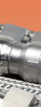


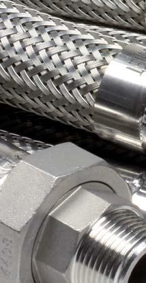

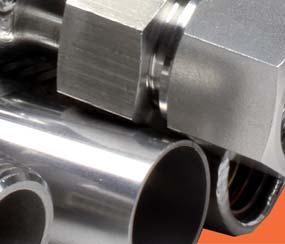

1 FLEXIBLE HOSES FOR FLUIDS AND GASES: ANACONDA CORRUGATED HOSES TYPE BW656, BW756, BW856, BW956, BW673 & ANAFLEX

2 HOSE SELECTION TABLE Hose Material Material Size (mm) Temp. ( C) Type Hose Braid Min. Max. Min. Max. BW 656 BW 756 BW 856 BW 956 Stainless steel AISI-316L Stainless steel AISI-316L Stainless steel AISI-316L Stainless steel AISI-316L Stainless steel AISI-304 Stainless steel AISI-304 Stainless steel AISI-304 Stainless steel AISI Pressure Rating Standard up to medium Page Medium High Extra High 1-08 BW 673 LOOSE BRAID ANAFLEX Monel 400 Monel Stainless steel AISI-316L Stainless steel AISI-304 Stainless steel AISI-304 Standard up to medium Standard / Heavy Standard 1-32 The end connections for hoses BW656, BW756, BW856, BW956 and BW673 are described on pages 1-11 till The self-mountable fittings for ANAFLEX are described on page In addition, and on request, we also can supply : - GMA gas meter connection - Fully interlocked (UI) Casing as mechanical hose protection. - Hiprojacket heat protection products. - Rubber hoses for fluids. - Teflon hoses for fluids. - Vibration eliminators. - Expansion joints. This corrugated hose catalogue supersedes all previous corrugated hoses catalogues. Information and technical details are subject to change without notifi cation. 1-01


 governs the maximum working pressure regardless of the number of braid layers.")

3 ENGINEERING DATA GENERAL INTRODUCTION ANACONDA metal hose is the leader in the fl exible hose fi eld since our beginning in ANACONDA stands for a complete line of fl exible products, such as corrugated metal hose, stripwound hose, metal bellows and expansion joints, vibration eliminators, Sealtite electrical wiring conduit and specially designed fl exible connectors for many applications. Our leadership in the fi eld was made possible by years of dedication to producing only the highest quality metal hose products available. Strict quality control guidelines, coupled with modern manufacturing practices and an expert team of engineers and research and development personnel, assures the best possible products and technical services. Special hose assemblies for unique applications can be designed by our engineering department and manufactured to meet specifi c customer requirements. Highly-trained sales representatives located in offi ces all over the world are only part of our dedicated customer service network. Contact your nearest ANAMET representative for assistance. ANACONDA products are manufactured by ANAMET Electrical, Inc., Mattoon, Illinois, USA; ANAMET Canada Inc., Frankfort, Ontario, Canada and ANAMET EUROPE B.V., Amsterdam, The Netherlands. CORRUGATED METAL HOSE - what it is..,how it is made.., where it is used.. Open pitch may be used where high fl exibility is not essential. Pitch can affect fl exibility and it varies from one manufacturer to another. Specifi cations on open pitch are available by contacting your ANAMET representative. For higher pressure applications, one or more wire braid coverings are applied to the corrugated hose. Braiding prevents hose elongation under pressure, dampens vibration and provides some mechanical protection for the inner core. Two or more braids are available to increase pressure capabilities of certain corrugated product lines; however, the deformation pressure (a point where corrugation material would Open Pitch Closed Pitch yield or elastically deform) governs the maximum working pressure regardless of the number of braid layers. A corrugated metal hose is defi ned as a length of tubing made fl exible by forming convolutions so that it may be readily bent while remaining liquid- and gas-tight. ANACONDA corrugated hose is made by thin wall tubing, corrugated into annular profi les. The annular hose profi le is designed so that each convolution is a complete circle or ring in itself. Corrugated hose is pressure tight and is particularly adapted to continuous fl exing or vibration. It is available in closed pitch or open pitch. Closed pitch is standard, unless otherwise specifi ed. HOSE ASSEMBLY DESIGN CONSIDERATIONS Flow velocity Extremely high conveyant velocities in corrugated hose should be avoided as the corrugations could be forced into resonant vibration resulting in premature fatigue failure. Consult your ANAMET representative for applications involving fl ow velocities in excess of 35 m/s for braided hose and 6 m/s for unbraided hose. Pressure Pressure capabilities shown in the various hose tables are based on constant pressures. For pulsating or shock pressures consult your ANAMET representative. 1-02
4 ENGINEERING DATA GENERAL Temperature HOSE ASSEMBLY DESIGN CONSIDERATIONS - CONTINUED As the temperature of metal hose increases, the pressure capability decreases. The factors shown below should be used to adjust the pressure capabilities at higher temperatures Temperature correction factors As the service temperature increases, a hose assembly maximum pressure rate decreases. The maximum allowable pressure of the hose assembly shall be the lowest of any method of assembly (mechanical, soldered, welded, silver brazed). By using the factors given in the table on the right, the approximate safe working pressure, at elevated temperatures, can be calculated for assemblies with welded or mechanically attached fi ttings. Example Given: Maximum operating temperature 350 C Maximum operating pressure 30 bar. Determine: Is 20 mm BW656-1S (hose AISI 316L with braid AISI 304) with welded steel fi ttings satisfactory for the given operating conditions? From the hose capability chart the working pressure for 20 mm BW656-1S is 70 bar. The largest correction factor at 350 C is now determined, in this case 0,49 for the AISI 304 braid (see table). Calculation: 70 bar x 0,49 indicates an allowable working pressure of 34,3 bar at 350 C. Temp. in C Steel AISI-304 AISI-321 AISI-316L Monel Bronze 20/ ,98 0,90 0,93 0,90 0,96 0, ,90 0,73 0,83 0,73 0,87 0, ,89 0,66 0,78 0,67 0,83 0, ,86 0,60 0,74 0,61 0,80 0, ,82 0,55 0,70 0,58 0, ,76 0,51 0,66 0,53 0, ,73 0,49 0,64 0,51 0, ,70 0,48 0,62 0,50 0, ,41 0,46 0,60 0, ,24 0,46 0,59 0, ,46 0,58 0, ,34 0, , Solution: The hose BW656-1S will meet the required conditions outlined above. Corrosion Recommended alloy selection to provide satisfactory performance with various media can be found in the corrosion resistance table on page
5 1-04 ANACONDA MULTIFLEX ENGINEERING DATA GENERAL Motion movement Length Installation Precautions Hose assemblies must be installed so that all motion/movement is in the bending plane. Metal hose when fl exed out of its bending plane will be subjected to torsion/twisting which develops a shear stress that can result in produce early hose failure. Braided hose must not be subjected to axial motion. Extension will result in preloading the braid. Compression will cause braid slack and can result in squirm of the corrugated core. Abrasion Allow for suffi cient clearance so that hose in motion will not come in contact with adjacent objects. Where abrasion cannot be avoided, an overall casing is required to protect the hose from external damage. Safety factor We suggest that the maximum working pressures be no more than 25% of the rated burst pressure of the hose assembly after correcting for service temperature. Circumstances may require safety factors greater than 4 :1. Testing Depending on diameter, length, pressure, type of hose and end fi tting design, hose assemblies are tested in various ways. It is ANAMET s standard practice to test assemblies by using one or more of the following methods: vacuum, hydrostatic, pneumatic or dye penetrant. Test media include: air, nitrogen, helium, water or oil. If special testing is required, it must be detailed at the time of an inquiry. Tolerances The standard tolerances used by ANAMET are found to be acceptable by most users. When tolerance considerations are critical, consult your ANAMET representative. Cleaning Depending on the medium being conveyed, special cleaning practices are sometimes necessary. ANAMET has special cleaning procedures where cleaning to standard commercial levels is not acceptable. Where special cleaning is necessary, requirements must be clearly specifi ed. End connections HOSE ASSEMBLY DESIGN CONSIDERATIONS - CONTINUED The active or exposed length of a hose assembly must be suffi cient to meet the conditions of movement. Lengths shorter than suggested can result in premature fatigue failure. Length tolerances as per our Quality Assurance Programme. Bend Radius The bend radius shown in the various hose tables are adequate to meet most industrial fl exing requirements. Consideration should be given to those applications involving levels of high frequency or large amounts of travel by increasing the bend radius. Avoid sharp bends except where the installation is permanent and no additional fl exing is expected. To prevent overbending of the hose, an overall casing can be used. The use of fl exible metal hose is complimented by the extensive range of end connections that are available. Such end connetions may be male or female pipe threads, unions, fl anges, fl ared tube fi ttings or other specially designed connectors. End connections are attached by welding, silver brazing, soldering and occasionally by mechanical means, depending on the type of hose and the alloy. In this catalogue a selection of various end connections are mentioned. For further detail or end connections that are not listed in the catalogue, please consult your ANAMET representative.
6 STANDARD UP TO MEDIUM PRESSURE BW 656 Anaconda butt welded corrugated stainless steel hose type BW656 is designed for conveying chemicals, gases, steam, etc. It is suitable for use under full vacuum and has a temperature range of cryogenic to ca C*. Type BW656 is designed for general purpose service and will meet most pressure requirements. It has a good fl exibility and a good fl exural strength, suitable for normal industrial vibrations. Burst pressure: The burst pressure of hose with braid is at least 4 times the working pressure. Material specifications: The core is manufactured from stainless steel AISI 316L (1.4404) with a standard stainless steel AISI 304 (1.4301) wire braid covering. Other alloys are available; consult your Anamet representative. Types: BW656-0 corrugated stainless steel hose, unbraided BW656-1S corrugated stainless steel hose, with one standard braid BW656-2S corrugated stainless steel hose, with two standard braids Nominal I.D. Type Max Min c/l Bending Radius** Min. exposed Rated pressure data at 20 C*** Approx. O.D. Flexing Permanent length for normal Max working Max test weight (mm) (inch) (mm) bend (mm) bend (mm) vibration (mm) pressure (bar) pressure (bar) (Kg/m) 6 1/4" BW , , BW656-1S 11, ,16 8 5/16" BW , , BW656-1S 13, , /8" BW , , BW656-1S 15, , /2" BW , , BW656-1S 18, , /2" BW , , BW656-1S 21, , /4" BW , , BW656-1S 28, , " BW , , BW656-1S 34, , /4" BW , , BW656-1S 44, ,99 BW , , /2" BW656-1S 52, ,20 BW656-2S 55, ,70 BW , , " BW656-1S 63, ,47 BW656-2S 66, ,09 BW ,9 0,7 0,7 1, /2" BW656-1S 82, ,99 BW656-2S 85, ,86 BW ,0 0,7 0,7 1, " BW656-1S 100, ,00 BW656-2S 104, ,50 BW ,3 0,5 0,5 2, " BW656-1S 121, ,25 BW656-2S 125, ,25 BW ,3 0,4 0,4 2, " BW656-1S 150, ,85 BW756-2S 159, ,10 BW ,5 0,3 0,3 3, " BW656-1S 175, ,80 BW756-2S 184, ,40 Note: for bigger sizes see type BW756 (page 1-06) * For working temperatures above 400 o C environmental conditions are to be considered - consult your Anamet representative. ** It is recommendet to increase the minimum bend radius with 25% when high pressures or temperatures are involved. *** For temperatures higher than room temperature use the applicable temperature correction factor. 1-05
7 MEDIUM PRESSURE & LARGER SIZES BW 756 Anaconda butt welded corrugated stainless steel hose type BW756 is designed for conveying chemicals, gases, steam, etc. It is suitable for use under full vacuum and has a temperature range of cryogenic to ca C*. Type BW756 will meet most pressure requirements and is also available in the bigger sizes up to 14. It has a good fl exibility and a good fl exure life, suitable for normal industrial vibrations. Burst pressure: The burst pressure of hose with braid is at least 4 times the working pressure. Material specifications: The core is manufactured from stainless steel AISI 316L (1.4404) with a heavy stainless steel AISI 304 (1.4301) wire braid covering. Other alloys are available; consult your Anamet representative. Types: BW756-0 corrugated stainless steel hose, unbraided BW756-1H corrugated stainless steel hose, with one heavy braid Nominal I.D. Type Max Min c/l Bending Radius** Min. exposed Rated pressure data at 20 C*** Approx. O.D. Flexing Permanent length for normal Max working Max test weight (mm) (inch) (mm) bend (mm) bend (mm) vibration (mm) pressure (bar) pressure (bar) (Kg/m) /4" BW , , BW756-1H 50, , /2" BW , , BW756-1H 59, , " BW , , BW756-1H 70, , /2" BW ,0 0,7 0,7 1, BW756-1H 87, , " BW ,0 0,7 0,7 1, BW756-1H 101, , " BW ,2 0,5 0,5 2, BW756-1H 128, , " BW ,2 0,4 0,4 3, BW756-1H 155, , " BW ,8 0,3 0,3 5, BW756-1H 180, , " BW ,1 0,3 0,3 8, BW756-1H 238, , " BW ,5 0,3 0,3 10, BW756-1H 292, , " BW ,0 0,2 0,2 13, BW756-1H 345, , " BW ,0 0,2 0,2 20, BW756-1H 383, ,28 * For working temperatures above 400 o C environmental conditions are to be considered - consult your Anamet representative. ** It is recommendet to increase the minimum bend radius with 25% when high pressures or temperatures are involved. *** For temperatures higher than room temperature use the applicable temperature correction factor. 1-06

8 HIGH PRESSURE BW 856 Anaconda butt welded corrugated stainless steel hose type BW856 is designed for conveying chemicals, gases, steam, etc. It is suitable for use under full vacuum and as a temperature range of cryogenic to ca C*. Type BW856 engineered design and construction allows it to operate at higher pressures than the standard and medium series. Its durable construction makes it suitable for severe applications, vibrations and high pressures. Burst pressure: The burst pressure of hose with braid is at least 4 times the working pressure. Material specifications: The core is manufactured from AISI 316 L (1.4404) stainless steel with a heavy stainless steel AISI 304 (1.4301) wire braid covering. Other alloys are available; consult your Anamet representative. Types: BW856-0 corrugated stainless steel hose, unbraided BW856-1H corrugated stainless steel hose, with one heavy braid BW856-2H corrugated stainless steel hose, with two heavy braids Nominal I.D. Type Max Min c/l Bending Radius** Min. exposed Rated pressure data at 20 C*** Approx. O.D. Flexing Permanent length for normal Max working Max test weight (mm) (inch) (mm) bend (mm) bend (mm) vibration (mm) pressure (bar) pressure (bar) (Kg/m) BW , ,15 6 1/4" BW856-1H 11, ,26 BW856-2H 13, ,37 BW , , /8" BW856-1H 18, ,50 BW856-2H 20, ,70 BW , , /2" BW856-1H 24, ,89 BW856-2H 26, ,20 BW , , /4" BW856-1H 34, ,51 BW856-2H 36, ,95 BW , , " BW856-1H 41, ,03 BW856-2H 44, ,69 BW , , /4" BW856-1H 50, ,64 BW856-2H 53, ,39 BW , , /2" BW856-1H 59, ,96 BW856-2H 63, ,00 BW , , " BW856-1H 68, ,36 BW856-2H 71, ,74 BW ,0 0,7 0,7 3, /2" BW856-1H 87, ,77 BW856-2H 91, ,35 BW ,0 0,7 0,7 5, " BW856-1H 101, ,01 BW856-2H 105, ,90 BW ,2 0,5 0,5 4, " BW856-1H 127, ,81 BW856-2H 131, ,97 BW ,6 0,3 0,3 5, " BW856-1H 180, ,26 BW856-2H 185, ,14 * For working temperatures above 400 o C environmental conditions are to be considered - consult your Anamet representative. ** It is recommendet to increase the minimum bend radius with 25% when high pressures or temperatures are involved. *** For temperatures higher than room temperature use the applicable temperature correction factor. 1-07

9 EXTRA HIGH PRESSURE BW 956 ANACONDA butt welded corrugated stainless steel hose type BW 956 is designed for conveying chemicals, gases, steam, etc. It is suitable for use under full vacuum and has a temperature range of cryogenic to ca C*. The engineered design and construction allows it to operate at higher pressures than the BW856 type. Its extra durable construction makes it suitable for severe applications, vibrations and extreme high pressures. Burst pressure: The burst pressure of hose with braid is at least 4 times the working pressure. Material specifications: The core is manufactured from AISI 316L (1.4404) stainless steel with an extra heavy stainless steel AISI 304 (1.4301) wire braid covering. Other alloys are available; consult your Anamet representative. Types: BW956-0 corrugated stainless steel hose, unbraided BW956-1E corrugated stainless steel hose, with one extra heavy braid BW956-2E corrugated stainless steel hose, with two extra heavy braids Nominal I.D. Type Max Min c/l Bending Radius** Min. exposed Rated pressure data at 20 C*** Approx. O.D. Flexing Permanent length for normal Max working Max test weight (mm) (inch) (mm) bend (mm) bend (mm) vibration (mm) pressure (bar) pressure (bar) (Kg/m) 6 1/4" BW , , BW956-2E 17, , /8" BW , , BW956-2E 22, , /2" BW , , BW956-2E 27, , /4" BW , , BW956-2E 36, , " BW , , BW956-2E 44, , /4" BW , , BW956-2E 53, , /2" BW , , BW956-2E 63, , " BW , , BW956-2E 71, , /2" BW ,0 0,7 0,7 5, BW956-2E 91, , " BW ,0 0,7 0,7 6, BW956-3E 110, , " BW ,2 0,5 0,5 7, BW956-3E 136, ,55 * For working temperatures above 400 o C environmental conditions are to be considered - consult your Anamet representative. ** It is recommendet to increase the minimum bend radius with 25% when high pressures or temperatures are involved. *** For temperatures higher than room temperature use the applicable temperature correction factor. 1-08
10 EXTREME CORROSION RESISTANT BW 673 ANACONDA type BW673 is extremely resistant to corrosion, and is used to convey corrosive liquids and gases for applications that involve high pressure, temperatures up to +540 C*, vibration and fl exure. Type BW673 is designed for Chlorine applications. Applicable as transfer hose for tankcar, cargotank, tankbarge, etc. Burst pressure: The burst pressure of hose with braid is at least 4 times the working pressure. Material specifications: The hose and braid are manufactured from Monel 400. For other alloys please consult your Anamet representative. Types: BW673-0 corrugated Monel hose, unbraided BW656-1S corrugated Monel hose, with one Monel braid BW656-2S corrugated Monel hose, with two Monel braids Nominal I.D. Type Max Min c/l Bending Radius** Min. exposed Rated pressure data at 20 C*** Approx. O.D. Flexing Permanent length for normal Max working Max test weight (mm) (inch) (mm) bend (mm) bend (mm) vibration (mm) pressure (bar) pressure (bar) (Kg/m) BW ,9 9 13,4 0,19 6 1/4" BW673-1S 13, ,31 BW673-2S 14, ,43 BW ,7 6,2 9,3 0, /8" BW673-1S 17, ,40 BW673-2S 18, ,60 BW ,5 4,5 6,8 0, /2" BW673-1S 20, ,46 BW673-2S 22, ,64 BW ,0 3,4 5,2 0, /4" BW673-1S 28, ,64 BW673-2S 29, ,89 BW ,5 2,4 3,6 0, " BW673-1S 36, ,15 BW673-2S 38, ,61 BW ,7 1,4 2,1 0, /4" BW673-1S 47, ,46 BW673-2S 49, ,02 BW ,3 1 1,5 1, /2" BW673-1S 55, ,76 BW673-2S 57, ,41 BW ,9 0,7 1 1, " BW673-1S 67, ,16 BW673-2S 69, ,96 BW ,3 0,5 0,7 2, " BW673-1S 102, ,97 BW673-2S 105, ,46 BW ,3 0,3 0,4 3, " BW673-1S 127, ,27 BW673-2S 132, ,69 * For working temperatures above 400 o C environmental conditions are to be considered - consult your Anamet representative. ** It is recommendet to increase the minimum bend radius with 25% when high pressures or temperatures are involved. *** For temperatures higher than room temperature use the applicable temperature correction factor. 1-09

11 STAINLESS STEEL BRAIDING BRAID Anaconda braid type S (standard braid) and H (heavy braid) are mainly supplied in combination with our Anaconda butt-welded corrugated hoses type BW656, BW756, BW856 and BW956. However they can also be obtained as loose braids. Burst pressure: The burst pressure of hose with braid is at least 4 times the working pressure. Material specifications: The braids are manufactured from stainless steel AISI 304 (1.4301) wire. Other alloys are available; consult your Anamet representative. Types: S H E Standard braid Heavy braid Extra heavy braid (on demand) For hose I.D. Type Core Braid construction Coverage Rated pressure data at 20 C*** Approx. diametre Number Wires Wire grade Max. working Max. test weight (mm) (inch) (mm) of Strands per Strand diam. (mm) % pressure (bar) pressure (bar) (Kg/m) 6 1/4" 1S 9, , ,09 8 5/16 1S 12, , , /8" 1S 14, , , /2" 1S 20, , , /4" 1S 27, , , " 1S 32, , , /4" 1S 41, , , /2" 1S 50, , , " 1S 60, , , /2 1S 78, , , " 1S 96, , , " 1S 117, , , " 1S 146, , , " 1S 171, , ,60 For hose I.D. Type Core Braid construction Coverage Rated pressure data at 20 C*** Approx. diametre Number Wires Wire grade Max working Max test weight (mm) (inch) (mm) of Strands per Strand diam. (mm) % pressure (bar) pressure (bar) (Kg/m) 6 1/4" 1H 10, , , /8" 1H 16, , , /2" 1H 21, , , /4" 1H 31, , , " 1H 38, , , /4" 1H 47, , , /2" 1H 56, , , " 1H 64, , , /2 1H 83, , , " 1H 97, , , " 1H 123, , , " 1H 176, , ,88 *** The rated pressure data are based onh the combination with Anaconda hoses. For other combinations or other applications, please contact Anamet Europe B.V. for specifi c braid calculation. 1-10
.")

 (inch) A B C 6 1/4 59 50-13,7 x 2,2 10,2 x 1,6 / 13,5 x 1,8 10 3/8 60 50-17,2 x 2,3 17,2 x 1,8 12 1/2 62 50-21,3")

12 END CONNECTIONS Standard end connections figures: Figure 1 to 14 show the standard Anamet hose end connections. All connections are TIG-welded onto our corrugated hoses. Weld oxides can be removed by brushing with a plastic wire brush or by electrolytic cleaning (to be specifi ed on order). Next to our standard program, Anamet can supply their hose assemblies with a great variety of trade fi ttings, couplings, and custom designed fi ttings. Frequently used hose fi xtures are: DIN 2353 L- and S-series fi ttings, SAE J/514 JIC 37 fi ttings, SAE 3000 and 6000 lbs fl anges, DIN food couplings, Camlock coupling, Mann-tek Dry disconnect couplings and custom fi ttings according to drawing. Please contact our Fluid and Gases sales team for our comprehensive service. Fig. 1 Welding end, hose Id. 1/4 to 4. - Carbon steel / Stainless steel Hose Nominal ID Dimensions in mm *C ANSI *C ISO (mm) (inch) A B C 6 1/ ,7 x 2,2 10,2 x 1,6 / 13,5 x 1,8 10 3/ ,2 x 2,3 17,2 x 1,8 12 1/ ,3 x 2,8 21,3 x 2,0 20 3/ ,7 x 2,9 26,9 x 2, ,4 x 3,4 33,7 x 2, / ,2 x 3,6 42,4 x 2, / ,3 x 3,7 48,3 x 2, ,3 x 3,9 60,3 x 2, / ,0 x 5,2 76,1 x 2, ,9 x 5,5 88,9 x 3, ,3 x 6,0 114,3 x 3,6 * If fi ttings with other dimension C are required please specify when ordering. Welding end, hose Id. 5 to 8. - Carbon steel / Stainless steel Hose Nominal ID Dimensions in mm *C ANSI *C ISO (mm) (inch) A B C ,3 x 6,5 139,7 x 4, ,3 x 7,1 168,3 x 4, ,1 x 8,2 219,1 x 5,9 1-11
 (inch) A B C A B C 6 1/4 38 29 1/4 BSPT 45 36 1/4 NPT 10 3/8 39 29 3/8 BSPT 46 36")
.")
13 END CONNECTIONS Fig. 2 Pipe nipple male (tapered thread). - BSPT Stainless steel - NPT Carbon steel / Stainless steel Hose Nominal ID Dimensions in mm Dimensions in mm (mm) (inch) A B C A B C 6 1/ /4 BSPT /4 NPT 10 3/ /8 BSPT /8 NPT 12 1/ /2 BSPT /2 NPT 20 3/ /4 BSPT /4 NPT BSPT NPT / /4 BSPT /4 NPT / /2 BSPT /2 NPT BSPT NPT / /2 BSPT /2 NPT BSPT NPT BSPT NPT Fig. 3 Hexagon nipple male (tapered thread). - BSPT Stainless steel - NPT Carbon steel / Stainless steel Hose Nominal ID Dimensions in mm Dimensions in mm (mm) (inch) A B C A B C D 6 1/ /4 BSPT /4 NPT / /8 BSPT /8 NPT / /2 BSPT /2 NPT / /4 BSPT /4 NPT BSPT NPT / /4 BSPT /4 NPT / /2 BSPT /2 NPT BSPT NPT / /2 BSPT BSPT BSPT Fig. 4 Hexagon nipple male. (parallel thread). 60 cone seat + flat seat on hexagon, - BSPP Carbon steel / Stainless steel Hose Nominal ID Dimensions in mm (mm) (inch) A B C D 6 1/ /4 BSPP / /8 BSPP / /2 BSPP / /4 BSPP BSPP / /4 BSPP / /2 BSPP BSPP / /2 BSPP BSPP BSPP 135 * Hexagon nipple male is also available with fl at seat instead of 60 cone seat. 1-12
 (inch) A B C D C 6 1/4 36 27 1/4 BSPP 17 1/4 NPT 10 3/8 40 35 3/8 BSPP 22 3/8 NPT 12 1/2 52 40 1/2")

14 END CONNECTIONS Fig. 5 Round socket female. - BSPP Stainless steel - NPT Carbon steel / Stainless steel Hose Nominal ID Dimensions in mm (mm) (inch) A B C D C 6 1/ /4 BSPP 17 1/4 NPT 10 3/ /8 BSPP 22 3/8 NPT 12 1/ /2 BSPP 27 1/2 NPT 20 3/ /4 BSPP 33 3/4 NPT BSPP 40 1 NPT / /4 BSPP /4 NPT / /2 BSPP /2 NPT BSPP 70 2 NPT / /2 BSPP BSPP BSPP 125 Fig. 6 Hexagon socket female. - BSPP Stainless steel - NPT Stainless steel Hose Nominal ID Dimensions in mm (mm) (inch) A B C D 6 1/4'' 40,5 28,5 1/4'' BSPP /8'' /8'' BSPP /2" /2'' BSPP /4" /4'' BSPP " '' BSPP /4" /4'' BSPP /2" /2'' BSPP " '' BSPP 92 Fig. 7 Sphere cone nipple with hexagon swivel nut. - BSPP Carbon steel / Stainless steel Hose Nominal ID Dimensions in mm (mm) (inch) A B C D 6 1/ /4 BSPP / /8 BSPP / /2 BSPP / /4 BSPP BSPP / /4 BSPP / /2 BSPP BSPP 70 * Spherical cone nipple standard is AISI-316L. Unless specifi ed otherwise. 1-13

15 END CONNECTIONS Fig. 7A Hose Nominal ID Dimensions in mm (mm) (inch) A B C D E Sphere cone nipple with hexagon swivel nut (fi g.7) with hexagon adapter BSPP female. - Carbon steel / Stainless steel 6 1/ /4 BSPP / /8 BSPP / /2 BSPP / /4 BSPP BSPP / /4 BSPP / /2 BSPP BSPP Fig. 7B Sphere cone nipple with hexagon swivel nut (fi g.7) with hexagon adapter BSPP male (parallel thread). - Carbon steel / Stainless steel Hose Nominal ID Dimensions in mm (mm) (inch) A B C D E 6 1/ /4 BSPP / /8 BSPP / /2 BSPP / /4 BSPP BSPP / /4 BSPP / /2 BSPP BSPP Fig. 7C Sphere cone nipple with hexagon swivel nut (fi g.7) with welding adapter. - Carbon steel / Stainless steel Hose Nominal ID Dimensions in mm (mm) (inch) A B C-ISO C-ANSI D 6 1/ ,2 x 1, / ,5 x 1,8 13,7 x 2, / ,2 x 1,8 17,2 x 2, / ,3 x 2,0 21,3 x 2, / ,9 x 2,3 26,7 x 2, ,7 x 2,6 33,4 x 3, / ,4 x 2,6 42,2 x 3, / ,3 x 2,6 48,3 x 3, ,3 x 2,9 60,3 x 3,
16 END CONNECTIONS Fig. 7D Spherical cone nipple with hexagon swivel nut (fi g.7) with Hexagon adapter BSPT male (tapered thread). - Carbon steel / Stainless steel Hose Nominal ID Dimensions in mm (mm) (inch) A B C D E 6 1/ /4 BSPT / /8 BSPT / /2 BSPT / /4 BSPT BSPT / /4 BSPT / /2 BSPT BSPT Fig. 7E Spherical cone nipple with hexagon swivel nut (fi g.7) with hexagon adapter NPT male (tapered thread). - Carbon steel / Stainless steel Hose Nominal ID Dimensions in mm (mm) (inch) A B C D E 6 1/ /4 NPT / /8 NPT / /2 NPT / /4 NPT NPT / /4 NPT / /2 NPT NPT
17 END CONNECTIONS Fig. 9B Hexagon union BSPT male (tapered thread). EN ISO BW / cone seat / Male - Stainless steel Hose Nominal ID Dimensions in mm (mm) (inch) A B C D E 6 1/4'' /4'' BSPT /8'' /8'' BSPT /2" /2'' BSPT /4" /4'' BSPT " '' BSPT /4" /4'' BSPT /2" /2'' BSPT " '' BSPT Fig. 10B Hexagon Union BSPP Female. (parallel thread). EN ISO BW / cone seat / Female - Stainless steel Hose Nominal ID Dimensions in mm (mm) (inch) A B C D 6 1/4'' 47,5 35,5 1/4'' BSPP /8'' /8'' BSPP /2" /2'' BSPP /4" /4'' BSPP " '' BSPP /4" /4'' BSPP /2" /2'' BSPP " '' BSPP 92 Fig. 11 Hexagon union 3000 lbs NPT male (tapered thread). ANSI B16.11, forged to ASTM A182 - Carbon steel / Stainless steel Hose Nominal ID Dimensions in mm (mm) (inch) A B C D 6 1/4'' /4'' NPT /8'' /8'' NPT /2" /2'' NPT /4" /4'' NPT " '' NPT /4" /4'' NPT /2" /2'' NPT " '' NPT
18 END CONNECTIONS Fig. 12 Hexagon Union 3000 lbs NPT female (tapered thread). ANSI B16.11, forged to ASTM A182 - Carbon steel / Stainless steel Hose Nominal ID Dimensions in mm (mm) (inch) A B C D 6 1/4'' /4'' NPT /8'' /8'' NPT /2" /2'' NPT /4" /4'' NPT " '' NPT /4" /4'' NPT /2" /2'' NPT " '' NPT
 Hose Nominal ID Dimensions in mm Number (mm)")
19 END CONNECTIONS Fig. 13 Fixed flange NW 06 to NW 100 EN type 11 PN06 to PN40 - Carbon steel / Stainless steel FIXED FLANGES ACCORDING TO EN PN 06 (DIN 2631*) Hose Nominal ID Dimensions in mm Number (mm) (inch) A B C D E F G H of holes 10 3/ / / / / / Fixed flange NW 125 to NW 250 EN type 01 PN06 to PN40 - Carbon steel / Stainless steel PN 10 (DIN 2632*) Hose Nominal ID Dimensions in mm Number (mm) (inch) A B C D E F G H of holes 10 to 40 Use PN 40 dimensions 50 to 150 Use PN 16 dimensions PN 16 (DIN 2633*) Hose Nominal ID Dimensions in mm Number (mm) (inch) A B C D E F G H of holes 10 to 40 Use PN 40 dimensions / / 8* PN 25 (DIN 2634*) Hose Nominal ID Dimensions in mm Number (mm) (inch) A B C D E F G H of holes 10 to 150 Use PN 40 dimensions * The European standard EN is based on the old DIN- standard. However, there are a few small differences. 1-18
20 END CONNECTIONS Fig. 13 Fixed flange NW 06 to NW 100 EN type 11 PN06 to PN40 - Carbon steel / Stainless steel FIXED FLANGES ACCORDING TO EN PN 40 (DIN 2635*) Hose Nominal ID Dimensions in mm Number (mm) (inch) A B C D E F G H of holes 10 3/ / / / / / Fixed flange NW 125 to NW 250 EN type 01 PN06 to PN40 - Carbon steel / Stainless steel * The European standard EN is based on the old DIN- standard. However, there are a few small differences. 1-19
21 END CONNECTIONS Fig. 14 FLOATING FLANGES ACCORDING TO EN Floating flange NW 06 to NW 100 EN type 02/33 (thin plate collar) PN10 Carbon steel / Stainless steel PN 10 (DIN 2641 FORM G*) Hose Nominal ID Dimensions in mm Number (mm) (inch) A B C D E F G H of holes 10 3/ , / , / / / / * For pressure ratings PN16 and PN40 Type 37,35 and 34 collars are available upon request. Floating flange NW 125 to NW 200 EN type 02/33 (thin plate collar) PN10 Carbon steel / Stainless steel * The European standard EN is based on the old DIN- standard. However, there are a few small differences. 1-20
22 END CONNECTIONS Fig. 14 Floating flange NW 06 to NW 100 EN type 02/32 (thick collar) PN06 to PN40 - Carbon steel / Stainless steel FLOATING FLANGES ACCORDING TO EN PN 06 (DIN 2641*) Hose Nominal ID Dimensions in mm Number (mm) (inch) A B C D E F G H of holes 10 3/ / / / / / Floating flange NW 125 to NW 250 EN type 02/32 (thick collar) PN06 to PN40 - Carbon steel / Stainless steel PN 10 (DIN 2642*) Hose Nominal ID Dimensions in mm Number (mm) (inch) A B C D E F G H of holes 10 to 40 Use PN 40 dimensions 50 to 150 Use PN 16 dimensions PN 16 (DIN 2643*) Hose Nominal ID Dimensions in mm Number (mm) (inch) A B C D E F G H of holes 10 to 40 Use PN 40 dimensions / / 8* * The European standard EN is based on the old DIN- standard. However, there are a few small differences. 1-21
23 END CONNECTIONS Fig. 14 FLOATING FLANGES ACCORDING TO EN Floating flange NW 06 to NW 100 EN type 02/32 (thick collar) PN06 to PN40 - Carbon steel / Stainless steel PN 25 (DIN 2644*) Hose Nominal ID Dimensions in mm Number (mm) (inch) A B C D E F G H of holes 10 to 150 Use PN 40 dimensions Floating flange NW 125 to NW 250 EN type 02/32 (thick collar) PN06 to PN40 - Carbon steel / Stainless steel PN 40 (DIN 2635*) Hose Nominal ID Dimensions in mm Number (mm) (inch) A B C D E F G H of holes 10 3/ / / / / / * The European standard EN is based on the old DIN- standard. However, there are a few small differences. 1-22
24 END CONNECTIONS Fig. 13 FIXED FLANGES ACCORDING TO ANSI / ASME B16.5 Fixed flange 1/2 to 4 ANSI welding neck / RF Pressure class 150 lbs, 300 lbs Carbon steel / Stainless steel ANSI 150 lbs. Hose Nominal ID Dimensions in mm Number (mm) (inch) A B C D E F G H of holes 12 1/ ,0 89,0 11,2 1,6 60,5 16, / ,0 98,5 12,7 1,6 70,0 16, ,0 108,0 14,2 1,6 79,5 16, / ,5 117,5 15,7 1,6 89,0 16, / ,0 127,0 17,5 1,6 98,5 16, ,0 152,5 19,1 1,6 120,5 19, / ,0 178,0 22,4 1,6 139,5 19, ,0 190,5 23,9 1,6 152,5 19, ,0 228,5 23,9 1,6 190,5 19, ,5 254,0 23,9 1,6 216,0 22, ,0 279,5 25,4 1,6 241,5 22, ,0 343,0 28,4 1,6 298,5 22, ,0 406,5 30,2 1,6 362,0 25,5 12 Fixed flange 5 to 10 ANSI Slip-on / RF Pressure class 150 lbs, 300 lbs Carbon steel / Stainless steel ANSI 300 lbs. Hose Nominal ID Dimensions in mm Number (mm) (inch) A B C D E F G H of holes 12 1/ ,0 95,0 14,2 1,6 66,5 16, / ,0 117,5 15,7 1,6 82,5 19, ,0 124,0 17,5 1,6 89,0 19, / ,5 133,5 19,0 1,6 98,5 19, / ,0 155,5 20,6 1,6 114,5 22, ,0 165,0 22,3 1,6 127,0 19, / ,0 190,5 25,4 1,6 149,0 22, ,0 209,5 28,4 1,6 168,5 22, ,0 254,0 31,7 1,6 200,0 22, ,5 279,5 35,0 1,6 235,0 22, ,0 317,5 36,5 1,6 270,0 22, ,0 381,0 41,1 1,6 330,0 25, ,0 444,5 47,7 1,6 387,5 28,
25 END FITTINGS Fig. 14 Floating flange 1/2 to 4 ANSI lap joint with stub-end. Pressure class 150 lbs, 300 lbs Carbon steel / Stainless steel Floating flange 5 to 10 ANSI lap joint with stub-end. Pressure class 150 lbs, 300 lbs Carbon steel / Stainless steel FLOATING FLANGES ACCORDING TO ANSI / ASME B16.5 ANSI 150 lbs. Hose Nominal ID Dimensions in mm Number (mm) (inch) A B C D E F G H of holes 12 1/ ,0 89,0 9,6 2,11 60,5 16, / ,0 98,5 11,1 2,11 70,0 16, ,0 108,0 12,6 2,77 79,5 16, / ,5 117,5 14,1 2,77 89,0 16, / ,0 127,0 15,9 2,77 98,5 16, ,0 152,5 17,5 2,77 120,5 19, / ,0 178,0 20,8 3,05 139,5 19, ,0 190,5 22,3 3,05 152,5 19, ,0 228,5 22,3 3,05 190,5 19, ,5 254,0 22,3 3,40 216,0 22, ,0 279,5 23,8 3,40 241,5 22, ,0 343,0 26,8 3,80 298,5 22, ,0 406,5 28,6 4,20 362,0 25,5 12 ANSI 300 lbs. Hose Nominal ID Dimensions in mm Number (mm) (inch) A B C D E F G H of holes 12 1/ ,0 95,0 12,6 2,11 66,5 16, / ,0 117,5 14,1 2,11 82,5 19, ,0 124,0 15,9 2,77 89,0 19, / ,5 133,5 17,4 2,77 98,5 19, / ,0 155,5 19,0 2,77 114,5 22, ,0 165,0 20,7 2,77 127,0 19, / ,0 190,5 23,8 3,05 149,0 22, ,0 209,5 26,8 3,05 168,5 22, ,0 254,0 30,1 3,05 200,0 22, ,5 279,5 33,4 3,40 235,0 22, ,0 317,5 34,9 3,40 270,0 22, ,0 381,0 39,5 3,80 330,0 25, ,0 444,5 46,1 4,20 387,5 28,


26 ENGINEERING DATA IMPORTANT POINTS WHEN INSTALLING HOSE ASSEMBLIES AXIAL LOAD Axial compression may lead to squirm of the corrugated hose. Axial tension lowers the pressure capacity of braided hose. RIGHT WRONG BENDING Install a hose in its most natural loop. Overbending lowers the pressure capacity and the cycle life WEIGHT The weight of the hose and the medium must be supported adequately. TORSION Torsion must be avoided. Torsion occurs when the movements are not in the same plane as the fi ttings. INSTRUCTIONS FOR SELECTING, INSTALLATING AND MOUNTING The life time of metal hoses will increase when the following instructions are implemented: 1. Select the right fi ttings Whenever possible select at least one swivel fi tting or a fl oating fl ange. This avoids torsion problems during installation. 2. Do not overbend the hose (check technical data) Avoid overbending, specially close to the fi ttings. Install the hose in its most natural position, free of kinks and sharp bends. 3. Do not torque a corrugated metal hose Torsion can have dramatic consequences on the life of a corrugated metal hose. Torsion occurs when the movements are not in the same plane as the fi ttings. Use two keys when fi xing swivel nuts. Note: Stripwound hose can absorb some torsion. 4. Avoid scratching over rough surfaces The braiding is the essential part of a hose assembly to withstand the internal pressure. A damaged braid diminishes the pressure capacity of the assembly and is detrimental to its function. 5. Avoid exposure to weld or grinding splatters Weld or grind splatters may lead to corrosion of the stainless steel parts. Use a heat proof shield (no plastic!) during welding or grinding in the proximity of metal hoses. 1-25
27 ENGINEERING DATA DETERMINING MINIMUM OVERALL LENGTH FOR INTERMITTENT FLEXURE From the minimum c/l bend radius for fl exing bend column in the hose specifi cations, obtain the proper bend radius for the type and size of hose chosen. Use the formulae below to calculate the length A of the exposed hose required. Determine the overall length of fi ttings from fi tting specifi cation pages and add to the exposed length of hose A to arrive at the assembly overall length. Distance between end connections should be such that there is no stress on the hose in the extreme offset position. FOR INTERMITTENT FLEXURE Use formulae and table for K below to determine the required hose length A. Formula A = 2,8 R h x 2S B = K x A * When S 0,5R h,otherwise another installation is required. In order to fi nd the overall length, add the length of the fi ttings to the calculated length A. Example Hose nominal I.D. 32 mm. Type BW656-1S, min. c/l bend radius for fl exing bend R h = 230 mm from table. Desired movement S = 80 mm, 0,5R h = 0,5 x 230 = 115 S(=80) 115 is allowed. Calculation A = 2,8 230 x 2 x 80 = 537 mm A/S = 537 / 80 = 6,71 K = 0,988 (see table K ) B = 0,988 x 537 = 531 mm FOR NON-MOVING OFFSET INSTALLATIONS Use formulae and table for K below to determine the required hose length A. Formula A = 2 R e x 2S B = K x A * When S 1,5R e,otherwise another installation is required. In order to fi nd the overall length, add the length of the fi ttings to the calculated length A. Example Hose nominal I.D. 50 mm. Type BW856-1H, min. c/l bend radius for permanent bend R e = 140 mm from table. Desired movement S = 120 mm, 1,5R e = 1,5 x 140 = 210 S(=120) 210 is allowed. Calculation A = x 2 x 120 = 366 mm A/S = 366 / 120 = 3,05 K = 0,930 (see table K ) B = 0,930 x 366 = 340 mm EXPLANATION OF FORMULA A = Exposed length of hose B = Installed length of hose (as illustrated) S = Lateral movement K = Factor, see table below R h = min. c/l bend radius for fl exing bend R e = min. c/l bend radius for permanent bend TABLE FOR K A/S 2 2,5 3 3,5 4 4, K 0,825 0,897 0,928 0,947 0,960 0,970 0,975 0,985 0,990 0,993 0,994 0,995 0,996 0,997 0,997 0,
28 ENGINEERING DATA The illustration on the right shows the proper method of installing hose in vertical loops. The formula and the table for B will aid in determining the overall length of an assembly. Formula Overall length= B + 0,5. A + 0,5S Data Using 25 mm type BW856-1H hose with fi ttings attached. VERTICAL LOOP FOR MAXIMUM VERTICAL TRAVEL Example A = 230 x 2 = 460 mm (2x minimum c/l bend radius for fl exing bend, see table type BW856). B = 410 mm (from table B ) S = 200 mm (desired movement) Overall length= , = 1232,6 mm or appr mm. VERTICAL LOOP FOR SHORT HORIZONTAL TRAVEL The formula and the table for B will aid in determining the overall length for an assembly when installed as illustrated in the drawing on the right. Formula Overall length = B + 0,5 (A + S) C = A + B +(0,5. S) 2 Data Using 10 mm type BW656-1S, with fi ttings attached. Example A =150 x 2 = 300 mm (2x min. c/l bend radius for fl exing bend, see type BW 656). B = 280 mm (from table B ) S = 250 mm (desired movement) Overall length = ,5 ( ) = 1143,9 mm or appr mm. C = (0,5. 250) 2 C = 486,3 mm or appr. 490 mm. HORIZONTAL LOOP FOR MAXIMUM HORIZONTAL TRAVEL The illustration on the right is another example of a typical installation of hose in which the movement is horizontal. The purpose of the support is to prevent the hose from sagging and causing failure near the fi ttings. Formula Overall length= B + 0,5. A + 0,5S Data Using 12 mm type BW856-1H hose with fi ttings attached. Example A = 2 x 205= 410 mm (2x minimum c/l bendradius for fl exing bend, see type BW856) B = 310 (from table B ) S = desired movement 550 mm Overall length= 310+(0,5. 410) +( 0,5 x 550)=1229 mm or appr mm. support for fl exible tubing EXPLANATION OF FORMULA A = Bend diameter (2 x R h ) B = Factor including the length of fi ttings and allowance for straight sections beyond each fi tting. S = Movement C = Required free height R h = min. c/l bend radius for fl exing bend R e = min. c/l bend radius for permanent bend TABLE FOR B Inside hose mm Diameter inch 1/4" 3/8" 1/2" 3/4" 1" 1.1/4" 1.1/2" 2" 2.1/2" 3" 4" 5" 6" 8" 10" B mm

29 ENGINEERING DATA MISALIGNMENT AND OFFSET MOVEMENTS For intermittent offset movement consult offset formula on page 9 and the minimum c/l bend radius for fl exing bend columns in specifi cations for each type and size of corrugated hose. For misalignment and ease of installation where there is no signifi cant movement or vibration, consult offset formula on page 9 and minimum c/l bend radius for permanent bend columns in specifi cations for each type and size of corrugated hose. MULTIPLE MOVEMENTS To absorb movements in several directions and at several planes, a 90 fl exible hose assembly is recommended, made up out of two short fl exibles which are connected by a 90 pipe angle. At both ends of the assembly swivel fl anges are used for connection to the piping system. This is important in order to avoid tension of the fl exible hoses during installation. The required length of the hoses is determined by various movements. Torsion on account of these movements will then be absorbed by both hoses. Dog leg construction VIBRATION Normal vibration encountered in average industrial applications is illustrated in the chart on the right. Under these conditions the exposed length of hose (Dimension L, drawing at right), should never be shorter than length given in min. exposed length for normal vibration in specifi cations for each type and size of corrugated hose. Defi nitions Amplitude equals lateral displacement from c/l of hose. Double amplitude equals lateral displacement on both sides of hose or 2 times the amplitude. Cycles per second Excessive vibration premature failure Normal industrial vibration range Amplitude in mm 1-28
30 CORROSION RESISTANCE TABLE The following tables may be used only as a guide in the selection of the most suitable hose and fi tting material for a given medium. The listed media are in general considered to be pure, at room temperature and, unless otherwise specifi ed, dry. A change in any one of these conditions may change the rating. No attempt has been made to account for variations in service conditions since these variables are too innumerable and complex. Additional information on service life, etc., is keyed to the notes behind the rating code A, B or C. Dry can also be referred to as anhydrous. When there is a question about this reference table or you have unusual service conditions or media, contact us before ordering. RATING CODE A - Suitable (normal condition) B - Limited Service C - Unsuitable Monel Carbon steel Stainless Stainless 304L/ L Acetaldehyde A B A A Acetanilide B B B B Acetic acid B C B 1 A 1 Acetic anhydride B C B B Acetone A C B B Acetophenone A A B B Acetylene A A A A Acrylates B B B B Acrylic acid B C B B Acrylonitrile A A A A Alcohols A A 5 A A Alum B C B B Alumina A A A A Aluminum acetate B C B B Aluminum chloride - dry A B A A Aluminum chloride - moist B C 3 C 3,4 C 3 Aluminum fl uoride B B C C Aluminum hydroxide B B A A Aluminum sulfate B C B 1,3 A 3 Ammonia - dry A A A A Ammonia - moist C C 3 A A Ammonium acetate A A A A Ammonium bromide B C C 4 C 4 Ammonium chloride - dry A B A A Ammonium chloride - moist B C C 3,4 C 3 Ammonium hydroxide 6 A B A A Ammonium nitrate C 2 C 3 A A Ammonium sulfate B C C 1 B Amyl acetate A A A A Amyl alcohol A A A A Amyl chloride - dry A B A A Amyl chloride - moist B C C 3,4 C 3 Aniline A C B B Aniline dyes A C B B Asphalt A A A A Atmosphere - industrial A C B 4 A 4 Atmosphere - marine A C B 4 B 4 Atmosphere - rural A C A A Barium carbonate B B B B Barium chloride - dry A A A A Barium chloride - moist B B C 3,4 C 3 Barium hydroxide B B B A Barium sulfate B B B B Barium sufi de C C B B Beer A C A A Beet sugar syrups A B A A Benzaldehyde B C B B Benzene (Benzol) A A A A Benzoic acid B C A A Benzylamine B B B B Benzyl chloride - dry A B A A Benzyl chloride - moist B C C 3,4 C 3 Black liquor, sulfate process A C B B NOTES 1 Susceptible to intergranular corrosion 2 May cause explosive reaction 3 Susceptible to stress corrosion cracking 4 Susceptible to pitting type corrosion 5 Discolors 6 Concentration over 50% and/or temperature over 95 C, refer to our engineering department. Monel Carbon Stainless Stainless steel 304L/ L Bleaching powder - dry A C A A Bleaching powder - moist B C C 1,3,4 C 3,4 Borax A B A A Bordeaux mixture A B A A Boric acid B C A A Boron trichloride - dry B A B B Boron trichloride - moist B B C 3,4 C 3 Boron trifl uoride - dry B A B B Brines B C C 3,4 C 3 Bromic acid C C C C Bromine - dry A C B B Bromine - moist B C C C Butadiene A A A A Butane A A A A Butanol (butyl alcohol) A A 5 A A Butyl phenols A B 5 B B Butylamine A A A A Butyric acid B C B B Cadmium chloride - moist B C C 3,4 C 3 Cadmium chloride - dry A A A A Cadmium sulfate A B A A Calcium bisulfi te B B B 1 B Calcium bromide B C C 3 C 3 Calcium chloride - moist B C C 3,4 C 3 Calcium chloride - dry A A A A Calcium fl uoride B C C C Calcium hydroxide B C B B Calcium hypochlorite - moist B C C 3,4 C 3,4 Calcium hypochlorite - dry A B A A Calcium nitrate B C 1 B 1 B Calcium oxide A A A A Cane sugar syrups A B A A Carbolic acid (phenol) B C B A Carbon dioxide - dry A A A A Carbon dioxide - moist A C A A Carbonated beverages A C A A Carbonated water A C A A Carbon disulfi de B B B B Carbon tetrachloride - dry A B A A Carbon tetrachloride - moist B C C 3,4 C4 Castor oil A A A A Chlorine - dry A B A A Chlorine - moist B C C 3,4 C 3 Chloroacetic acid B C C 3,4 C 3 Chloric acid C C C 3 C 3 Chlorine dioxide - dry A B A A Chlorine dioxide - moist B C C 3,4 C 3 Chloroform - dry A A A A Chloroform - moist B C C 3,4 C 3 Chromic acid B C 3 C 1,4 B Chromic fl uorides B C C C Chromic hydroxide B B B B Chromium sulfate B C B B 1-29
31 CORROSION RESISTANCE TABLE RATING CODE A - Suitable (normal condition) B - Limited Service C - Unsuitable Monel Carbon steel Stainless Stainless 304L/ L Cider A C A A Citric acid B C B B Coffee A C A A Copper chloride - dry A B A A Copper chloride - moist B C C 3,4 C 3 Copper nitrate C C A A Copper sulfate B C B 1 B Corn oil A A A A Cottonseed oil A A A A Creosole A A A A Crude oil A C C 1 B Cyclohexane B B B B DDT B 4 C A A Dichloroethane - dry A A A A Dichloroethane - moist B C C 4 C 4 Dichloroethylene - dry A B A A Dichloroethylene - moist B C C 4 C 4 Dichlorophenol B C B 3 B 3 Diisocyanate A B A A Dimethyl sulfate B B B B Epichlorohydrin - dry A C 4 A A Epichlorohydrin - moist B C 4 C 3,4 C 3 Ethane A A A A Ethers A B A A Ethyl acetate B B B B Ethyl alcohol A A A A Ethyl benzene B B B 3 B Ethyl chloride - dry A A A A Ethyl chloride - moist B C C 3,4 C 3 Ethylene A A A A Ethylene chlorohydrin - dry A B A A Ethylene chlorohydrin - moist B C C 4 C 4 Ethylene diamine B B B B Ethylene glycol A A A A Ethylene oxide B B A A Fatty acids B C B 1,4 A Ferric chloride - dry A B A A Ferric chloride - moist B C C 1,3,4 C 3,4 Ferric nitrate C C B B Ferric sulfate C C B 1 A Ferrous chloride - dry A B A A Ferrous chloride - moist B C C 3,4 C 3 Ferrous sulfate A C B 4 B Fluorine - dry A A A A Fluorine - moist B C C C Formaldehyde A 5 B 5 B B Formic acid B C B 1 A Freon A A A A Fruitjuices A C A A Fuel oil A C A A Furfural A B A A Gasoline A B A A Gelatine A C A A Glucose A B A A Glue A C A A Glutamic acid E 3 C B 3,4 B 3,4 Glycerin (glycerol) A B 5 A A Heptane A A A A Hexachloroethane - dry A B A A Hexachloroethane - moist B C C 4 C 4 Hydrazine C C A A Hydrobromic acid C C C 4 C Hydrocarbons, pure A A A A Hydrochloric acid B C C 4 C 4 Hydrocyanic acid B C 3 C 1,3 C 3 Hydrofl uoric acid B C C 1,3 C Hydrofl uorsilicic acid B C C C NOTES 1 Susceptible to intergranular corrosion 2 May cause explosive reaction 3 Susceptible to stress corrosion cracking 4 Susceptible to pitting type corrosion 5 Discolors 6 Concentration over 50% and/or temperature over 95 C, refer to our engineering department. Monel Carbon steel Stainless Stainless 304L/ L Hydrogen A A A A Hydrogen chloride - dry A B A A Hydrogen chloride - moist B C C 4 C 4 Hydrogen peroxide C C B B Hydrogen sulfi de - dry A B A A Hydrogen sulfi de - moist E 3 C 3 B 4 A Hydroquinone B B 5 B B Kerosine (kerosene) A B A A Lacquers A A A A Lacquer solvents A A A A Lactic acid B C B 1,4 B 1 Lime A B A A Lime - sulfur B C B B Linseed oil A B A A Lithium chloride - dry A B A A Lithium chloride - moist B B C 3,4 C 3 Lithium hydroxide B B B B Magnesium chloride - dry A B A A Magnesium chloride - moist B C C 3,4 C 3 Magnesium hydroxide A A A A Magnesium sulfate A B B A Maleic acid B B B 1 B Mercuric chloride - dry A B A A Mercuric chloride - moist B C C 3,4 C 3 Mercurous nitrate B 3 B B B Mercury B 3 B B B Methyl alcohol A A A A Methane A A A A Methyl chloride - dry A A A A Methyl chloride - moist B C C 3,4 C 3 Methyl ethyl ketone B B B B Milk A C A A Mine water B C B B Napthalene B A A A Natural gas A A A A Nickel chloride - dry A B A A Nickel chloride - moist B C C 3,4 C 3 Nitric acid C C A A Nitrotoluene B B B B Nitrogen A A A A Oleic acid A C B 4 B Oleum (fuming H2S04) C B 3 B B Axalic acid B C C 1 B 1 Oxygen A C A A Palmitic acid A C A A Parafi n A B A A Pentane B B B B Phenol (carbolic acid) B C B A Phosphoric acid B C C 1 B 1 Phthalic acid B C B 1 B Pitric acid C C B B Potassium bromide B C C C Potassium carbonate A B A A Potassium chloride - dry A A A A Potassium chloride - moist B C C 3,4 C 3 Potassium chromate B C B B Potassium cyanide A B B B Potassium dichromate A C A A Potassium fl uoride B C C C Potassium hydroxide A 3 B 3 B 3 A Potassium nitrate B B B A Potassium permanganate B B B B Potassium sulfate B C B B Propane A A A A Propylene A A A A Propylene oxide C C A A Propylene dichloride - dry A B A A 1-30
32 RATING CODE A - Suitable (normal condition) B - Limited Service C - Unsuitable CORROSION RESISTANCE TABLE NOTES 1 Susceptible to intergranular corrosion 2 May cause explosive reaction 3 Susceptible to stress corrosion cracking 4 Susceptible to pitting type corrosion 5 Discolors 6 Concentration over 50% and/or temperature over 95 C, refer to our engineering department. Monel Carbon steel Stainless Stainless 304L/ L Propylene dichloride - moist B C C 4 C 4 Pyridine B B 5 B B Pyrrolidine B B B A Quinine B C B B Rosin A C 5 A A Sea water B C C 3,4 C 3 Sewage A B A A Silver salts A C B B Silver nitrate C C 3 B A Soap solutions A B A A Sodium A A A A Sodium acetate B B B 4 B Sodium bicarbonate A C A A Sodium bisulfate B C B 1,4 A Sodium bisulfi te B 4 C B B Sodium bromide B B C C Sodium carbonate A B A A Sodium chlorate - dry A A A A Sodium chlorate - moist B C C 3,4 C 3 Sodium chloride - dry A B A A Sodium chloride - moist B C C 3,4 C 3 Sodium chromate A B A A Sodium citrate B B B B Sodium cyanide B B B B Sodium dichromate B C A A Sodium fl uoride A B C 4 C Sodium hydroxide 6 A B 3 B 3 B 3 Sodium hypochlorite - dry A B A A Sodium hypochlorite - moist B C C 1,4 C 4 Sodium metasilicate A B A A Sodium nitrate A B 3 A A Sodium nitrite B B B B Sodium peroxide B C A A Sodium phosphate A C A A Sodium silicate A B A A Sodium sulfate A B B 3 B Soldium sulfi de A C B 4 B Sodium sulfi te A C B B Sodium thiosulfate A C B B Stannic chloride - dry A B A A Stannic chloride - moist B C C 3,4 C 3 Stannous chloride - dry A B A A Stannous chloride - moist B C C 3,4 C 3 Steam A 3 C A A Stearic acid B C 5 B B Strontium nitrate B C B B Sulfate black liquor B B B B Sulfate green liquor B B B 3 B Sugar solutions A B A A Sulfur - dry A B A A Sulfur - molten C C C B Sulfur chloride - dry A C A A Sulfur chloride - moist B C C 3,4 C 3 Sulfur dioxide - dry B C C 1 B Sulfur dioxide - moist C C C 1 B Sulfur trioxide - dry A C A A Sulfuric acid, % B B A A Sulfuric acid, 80-95% B C B B Sulfuric acid, 40-80% C C C 1 C 1 Sulfuric acid, 40% C C C 1 C 1 Sulfurous acid B C C 1,4 C 1,4 Tail oil B B B B Tannic acid B C 5 B B Tar A B A A Tartaric acid B C B B Tetraphosphoric acid C C B B Toluene A A A A Monel Carbon steel Stainless Stainless 304L/ L Trichloroacetic acid B C C 3,4 C 4 Trichloroethane - dry A A A A Trichloroethane - moist B C C 4 C 4 Trichloroethylene - dry A A A A Trichloroethylene - moist B C C 4 C 4 Turpentine A B A A Varnish A B A A Vinegar B C A A Water, potable A C A A Xylene A B A A Zinc chloride - dry A A A A Zinc chloride - moist B C C 3,4 C 3 Zinc sulfate B C B A 1-31

, does not age and is diffusion-tight.")
33 ANAFLEX CORRUGATED HOSE: Quick and perfect solution for every HVAC installation ANAFLEX from Anamet Europe B.V. is the perfect fl exible solution for HVAC installations. The ideal solution for a great number of applications. The ANAFLEX system has been designed as a self-mounting fl exible hose system for heating, steam-tracing, cooling-ceilings, watersupply, boiler-connection, machine-fl uid-connection and solar-panel-connection applications. The fl exible ANAFLEX corrugated hose is made of high quality stainless steel (AISI-316L), does not age and is diffusion-tight. ANAFLEX solves the problem of rubber and plastic hoses, which due to oxygen-diffusion and ageing can damage the installation. The fl exible stainless steel hose is easy to handle and easy to cut to the desired length, which saves installation time. Material & Construction: Construction: Flexible parallel corrugated hose, made of thin wall stainless steel AISI-316L Temperature range: 0 ºC tot +110 ºC (for higher temperatures till +250 C please consult Anamet Europe B.V.). Colour: Metal. Product advantages: - No oxygen diffusion, prevents damage and does not block the installation. - Does not kink. - Durable and does not age. - Is corrosion resistant. Mounting advantages: - You decide the length on the spot. - Quick and effi cient mounting. - Smooth installation. - Very long life time. Standard corrugation Anafl ex Diametre Working- Bendingradius Metre Article No. Metre Article No. Metre Article No. Standard carton Small carton Reel Weight Size Inside Outside Pressure (Kg/m) DN (mm) (mm) (Bar) Static (mm) * DN 12 12,2 16, ,12 DN 16 16,2 21, ,20 DN 20 20,3 26, ,28 DN 25 25,4 32, ,39 * For dynamic applications, please consult your Anamet representative. The ANAFLEX stainless steel hoses can be used in combination with the unique ANAFLEX -CLICK fi ttings, as mentioned on the next page. This combination gives you many advantages: - You can install the fi ttings yourself. - Quick and effi cient working method. - Signifi cant installation time reduction. - Smooth and perfect result. Anaflex Male BSPT Female BSPP Pipe compression /8-1/2 1/2-3/4 3/ /8-1/2 1/2-3/4 3/ mm18-22 mm

 a tensile strong and liquid-tight connection is made.")

.")
 (mm) A B C D E Package Number")

 (mm) A B C D E Package")
34 ANAFLEX -CLICK FITTINGS: Nickel plated brass fittings with unique click-system. For the stainless steel ANAFLEX corrugated hose an unique mounting fi tting has been developed. The major advantage of the ANAFLEX -CLICK fi tting is the quick-mounting directly on the hose. After turning the backnut (2 till 3 full turns) a tensile strong and liquid-tight connection is made. The nickel plated brass fi ttings are suitable for cold and hot water as well as steam. Material & Construction: Construction: Nickel plated brass fi tting, consisting of 6 parts (body, counter nut, retaining ring and fi ller ring are nickel plated brass, internal sealing sleeve is from PTFE and the internal fl at seal is from silicone rubber). Special approvals: Click system tested and approved by the Institut für Solartechnik SPF (Switzerland). Temperature range: 0 ºC till +110 ºC (for higher temperatures please consult Anamet Europe B.V.). Colour: metal. Figure C3, nickel plated brass click fitting, male, BSPT Thread Anafl ex ID Hose Dimensions in mm Standard Article Weight size Size (DN) (mm) A B C D E Package Number (Kg/100) 3/8 BSPT DN 12 12, ,1 1/2 BSPT DN 12 12, /2 BSPT DN 16 16, ,7 3/4 BSPT DN 16 16, ,5 3/4 BSPT DN 20 20, ,0 1 BSPT DN 20 20, ,3 1 BSPT DN 25 24, ,8 Figure C6, nickel plated brass click fitting, female, BSPP Thread Anafl ex ID Hose Dimensions in mm Standard Article Weight size Size (DN) (mm) A B C D E Package Number (Kg/100) 3/8 BSPP DN 12 12, ,5 1/2 BSPP DN 12 12, ,8 1/2 BSPP DN 16 16, ,9 3/4 BSPP DN 16 16, ,8 3/4 BSPP DN 20 20, ,6 1 BSPP DN 20 20, ,1 1 BSPP DN 25 24, ,8 Figure C8, nickel plated brass click fitting, pipe compression. Pipe Anafl ex ID Hose Dimensions in mm Standard Article Weight diameter Size (DN) (mm) A B C D E Package Number (Kg/100) Ø 15 mm DN 16 16, ,9 Ø 18 mm DN 16 16, ,8 Ø 18 mm DN 20 20, ,6 Ø 22 mm DN 20 20, ,1 1-33


35 ENGINEERING DATA QUALITY ASSURANCE Within ANAMET EUROPE B.V. quality assurance is integrated in the corporate philosophy and adopted at all levels within the company. The objective of the company s Quality Assurance Programme is to operate a quality level conform to ISO In addition to the requirements and specifi cations of end-users ANAMET produces conform international regulatory standards of independent classifi cation authorities. ANAMET EUROPE B.V. is since 2002 certifi ed by Stoomwezen B.V. to produce fl exible hoses according to the Pressure Equipment Directive (PED) 97/23/EG, even up to category II. European HQ: Amsterdam Warehouse & Logistics Production Hose preparation zone Welding zone Testing zone Laboratory Warehouse facilities 1-34

36 ANAMET EUROPE B.V. Galwin AW Amsterdam Tel.: Fax.: sales@anamet.nl Website:
ANACONDA FLEXIBLE METAL HOSE
 ANACONDA FLEXIBLE METAL HOSE CORRUGATED HOSE STAINLESS STEEL : BW656-BW856-BW956 MONEL : BW673 BRONZE : BW794 1 COMPANY PROFILE. Anamet Europe BV is a specialist in the fi eld of fl exible connection and
ABS and DNV Type Approved Products
 ABS and DNV Type Approved Products For Marine & Offshore Applications Metal Hose Assemblies Exhaust Bellows Multipurpose Expansion Joints ABS Product & DNV Type Approval Metal Hose ABS Certificate Number
WHY METAL HOSE? SERVICE TESTING & CERTIFICATIONS THE QUALITY PROCESS
 Flexible METAL HOSE Is among the nation s leading flexible metal hose manufacturers with over 5 years of experience in the manufacture of metal hose products. We bring solid product and application experience
CONDUIT SYSTEMS FOR ELECTRICAL WIRES AND CABLES: ANACONDA CONDUIT AND FITTINGS FOR HYGIENIC DESIGN
 CONDUIT SYSTEMS FOR ELECTRICAL WIRES AND CABLES: ANACONDA CONDUIT AND FITTINGS FOR HYGIENIC DESIGN CONTENT PAGE Conduit selection table Anaconda Sealtite Food Grade Sealtite Material Material Temp. ( C)
Flexible metal hoses
 Flexible metal hoses General information Use of hoses of hoses of braiding Bending radius Thermal resistance Pressure resistance Protection of hoses Metal hoses are flexible corrugated metal pipes manufacture
Lifting Lug Standard on all units, for ease of installation. Multi-Ply Bellows Laminated bellows offer maximum flexibility and endurance ONS
 FIXED END PLATINUM SERIES SEP Internal Guide Ring Maintains alignment of inner pipe and housing, prevents contact of bellows with housing, and provides stop for maximum extension FIXED END Drain Standard
Fittings. Elbow Pipe. Specifications:
 Elbow Pipe This type of fitting is widely used in piping systems to connect two straight sections of pipes of equal or different nominal diameter and with a curvature at a certain angle to change its direction;
...our linkages, your solution. Rod Ends
 ...our linkages, your solution ov-rod-ends-divider - Updated - 12-01-2017 Technical Information Introduction All of our rod ends incorporate either a plain spherical bearing, ball bearing, or roller bearing.
Ends for Gates Hose. Four Types of Hose Ends
 Supersedes Many applications require hose with special ends to provide protection and better coupling for the hose. Ends for Gates Hose Four Types of Hose Ends To be sure you receive the proper hose end,
WYATT Orifice flow PrOducTs
 WYATT Orifice Differential producers, specifically orifice plates, are used in flow measurement due to their simplicity, ease of installation, tolerance to extreme atmospheric and process conditions, and
// INDEX // HOSE // FITTINGS ALFAGOMMA ALFAGOMMA // INDEX.
 STEAM ALFAGOMMA // INDEX // INDEX 2 ALFAGOMMA // HOSE 350AA Steam 6 bar (90 psi) - Hot water 15 bar (225 psi)...10 354AA Steam 6 bar (90 psi)...10 340AA Steam 18 bar (270 psi) - Steel braided...11 340AH
ANACONDA METAL HOSE ANACONDA METAL HOSE
 ANACONDA METAL HOSE ANACONDA METAL HOSE ANACONDA metal hose is the leader in the fl exible hose fi eld since our beginning in 1908. ANACONDA stands for a complete line of fl exible products, such as corrugated
East Central College
 SECTION 221116 - DOMESTIC WATER PIPING PART 1 - GENERAL 1.1 RELATED DOCUMENTS A. Drawings and general provisions of the Contract, including General and Supplementary Conditions and Division 01 Specification
SECTION EXPANSION FITTINGS AND LOOPS FOR HVAC PIPING
 SECTION 23 05 16 EXPANSION FITTINGS AND LOOPS FOR HVAC PIPING PART 1 - GENERAL 1.1 SUMMARY A. Section includes flexible pipe connectors, expansion joints and compensators, pipe loops, offsets, and swing
Expansion Joints Guide Module 6 - Low Pressure Expansion Joints General - Standard Program (EFB) - Installation Instructions - Technical Data
 - Installation Instructions - Technical Data") Expansion Joints Guide Module 6 - Low Pressure Expansion Joints General - Standard Program (EFB) - Installation Instructions - Technical Data BOA Expansion Joints Guide Expansion Joints Guide Summary Module
Expansion Joints Guide Module 6 - Low Pressure Expansion Joints General - Standard Program (EFB) - Installation Instructions - Technical Data BOA Expansion Joints Guide Expansion Joints Guide Summary Module
Series 5500 Bellows Pump Connectors Catalog 474E
 Series 5500 Bellows Pump Connectors Catalog 474E Series 5500 Bellows Pump Connectors Sizes 1-1 /2 through 24 Design Conditions: full vacuum to 150 and 300 psig at 500 F Compact design with maximum flexibility
DARTMOUTH COLLEGE DESIGN September 15, 2004 &CONSTRUCTION GUIDELINES
 PART 1 DESIGN DIRECTIVE 1.1 RELATED DOCUMENTS SECTION 15240 SEISMIC RESTRAINT AND VIBRATION CONTROL A. This section shall be considered as a part of each DC Standards, Part 15. 1.2 QUALITY ASSURANCE A.
Style 206 Product Specification
 Style 206 Product Specification 1.0 Application The Style 206 is used in rigid piping systems to compensate for axial, lateral, torsional and angular movement and misalignment due to thermal expansion
W A R R A N T Y. CSA standard B51 certified. Inspected and tested by the Technical Standards and Safety Authority of Canada.
 FLEX-HOSE PRODUCT REPLACEMENT WARRANTY EXCEEDS W A R R A N T Y INDUSTRY STANDARDS CSA standard B certified. Inspected and tested by the Technical Standards and Safety Authority of Canada. Rubber **NEOPRENE/NYLON
PAGE International designs and manufactures custom engineered Fluoropolymer
 PAGE International designs and manufactures custom engineered Fluoropolymer hose and tubing products for use in virtually any fluid transport application. From our modern production and testing facility
94110 Vacuum Vent. Features. Vacuum Vent. Less need for special materials in corrosive and extreme temperature
 The Shand & Jurs 94110 has been designed utilizing over 90 years experience in the development of quality safety and conservation fi ttings. The function of this vent is to relieve vacuum conditions in
Style 204 EPS Product Specification
 Style 204 EPS Product Specification 1.0 Application The Style 204 EPS is used in rigid piping systems to compensate for axial, lateral, torsional and angular movement and misalignment due to thermal expansion
Stainless Steel Aeration Equipment Specification
 Section 15 Stainless Steel Aeration Equipment Specification Part 1 - General 1.01 Description A. Scope of Work 1. Furnish, install and test aeration system including air mains, drop pipes, valves, expansion
Regulating valves REG 6-65, REG-SS 15-40
 MAKING MODERN LIVING POSSIBLE Technical brochure Regulating valves REG 6-65, REG-SS 15-40 REG are angle-way and straight-way regulating valves, which act as normal stop valves in closed position. The valves
FN04. Liquid level sensor with continuous detection. Level Measurement and Monitoring
 Level Measurement and Monitoring FN04 Liquid level sensor with continuous detection Level measurement unaffected by foam formation, conductivity, pressure or temperature Remote indication over very long
 Meter Swivels Insulated Unions Meter Sets Meter Accessories The Right Connection 1-800-654-3872 1-405-273-6302 www.centralplastics.com : Overview Georg Fischer Central Plastics entered the meter connection
SOP-10. Orifice Plate. Model. Description. Specifications. PLATE THICKNESS 3, 6, 9, 12mm
 Model SOP-10 Orifice Plate Description Orifice plates are widely used for measurement as they provide the simplest and the most economical means of flow detection. Orifice plates are available in the concentric
Standard Tube & Pipe Adapters
 Standard Tube & Pipe Adapters 1 to 8 OD Tube Sizes, 1 to 8 NPS Pipe Sizes Aluminum, Stainless Steel, Carbon Steel, Galvanized (Zinc-Coated) Steel. 11, 14, 16 Gauge Tube Wall Thicknesses; Schedule 5, 10,
1071 Cast Steel Globe Steam Stop Valve (Flanged)
") 1071 Cast Steel Globe Steam Stop Valve (Flanged) Flanged Ends to DIN 2545 PN 40. Straight Pattern, Outside Screw, Yoke Type, Rising Stem, Bolted Bonnet. Renewable 13% Cr. Stainless Steel (S.S 410) working
1071 Cast Steel Globe Steam Stop Valve (Flanged) Flanged Ends to DIN 2545 PN 40. Straight Pattern, Outside Screw, Yoke Type, Rising Stem, Bolted Bonnet. Renewable 13% Cr. Stainless Steel (S.S 410) working
Brown University Revised August 3, 2012 Facilities Design & Construction Standards SECTION HVAC PIPES AND TUBES
 SECTION 23 20 00 - HVAC PIPES AND TUBES PART 1 - GENERAL 1.1 SUMMARY: A. Section includes pipe and pipe fittings for: heating water, chilled water, steam and steam condensate, condenser water, glycol,
07 SWIVEL JOINTS 268
 07 7.01 The Range STRAIGHT SWIVEL JOINT Size : 1/2 to Working Pressure : 250 psi Page 270 90 SWIVEL JOINT Size : 1/2 to Working Pressure : 250 psi Page 271 FLANGED SWIVEL JOINT Size : 1/2 to Working Pressure
SPECIFICATIONS - DETAILED PROVISIONS Section Stainless Steel Sluice Gates C O N T E N T S
 SPECIFICATIONS - DETAILED PROVISIONS Section 11294 - Stainless Steel Sluice Gates C O N T E N T S PART 1 - GENERAL... 1 1.01 SUMMARY... 1 1.02 REFERENCES... 1 1.03 DEFINITIONS... 1 1.04 DESIGN REQUIREMENTS...
Tubing Data. Contents. Tubing Selection. Tubing Handling. Tubing Material. Tubing Outside Diameter Hardness. Tubing Wall Thickness
 www.swagelok.com Tubing Data Contents Gas Service...................................... 2 Tubing Installation................................. 2 Suggested Allowable Working Pressure Tables Carbon Steel
CLASSIFICATION NOTES. Type Approval. Mechanical Joints. used in Piping
 CLASSIFICATION NOTES Type Approval of Mechanical Joints used in Piping Revision 2 : January, 2014 Contents Sections 1. General 2. Scope 3. Documentation 4. Materials 5. Testing Procedure and Requirements
ALLOY BALL VALVES 7000 SERIES METAL AND SOFT SEATED 150# TO 2500#
 ALLOY BALL VALVES 7000 SERIES METAL AND SOFT SEATED 150# TO 2500# The Jarecki 7000 Series ball valves are available in a variety of materials, end connections, and seat materials. They are a proven in
Arms Group Drainage System. 1. Swivel Joint Type 2. Pivot Joint Type 3. Flexible Hose Type 4. Swing Master Joint Type 5. Floating Check Valve
 Arms Group Drainage System 1. Swivel Joint Type 2. Pivot Joint Type 3. Flexible Hose Type 4. Swing Master Joint Type 5. Floating Check Valve Swivel Joint Type Model No. 1010 Sizes 3in through 8in Heavy
Series 1500 Laminated Bellows Expansion Joints. Catalog 1103
 Series 1500 Laminated Bellows Expansion Joints Catalog 0 500 Laminated Bellows Expansion J Series 1500 on Laminated Joints Bellows Expansion Joints Sizes " through " IPS. Design conditions of full vacuum
Thermowells. Excellence the World can Measure TM. Temperature Products. Fabricated - Screwed & Flanged Connection. General Description.
 Thermowells abricated - Screwed & langed onnection Temperature Products ata sheet : TWELL2/2012 y Wide Range of Materials - Stainless Steels - Exotic Materials y hoice of Process onnections - langed -
Ball Float Steam Trap UNA 45, UNA 46, UNA 46A PN 40/Class 300 DN 15, 20, 25, 40, 50, 65
 Data Sheet 819345-02 Issue Date: 06/16 all Float Steam Trap UNA 45, UNA 46, UNA 46A PN 40/Class 300, 20, 25, 40, 50, 65 UNA 45 hl, UNA 46 hl, UNA 46A hl UNA 45 hl UNA 45 hl Description Float traps type
Meter Connection Products: Overview
 : Overview Georg Fischer Central Plastics entered the meter connection business in 1955 with the design and introduction of the insulated meter swivel and insulated union. We understand the critical nature
 Copper and Copper Alloy Tube, Pipe and Fittings COPPER and COPPER ALLOY TUBE and PIPE Seamless Copper Pipe: Copper pipe is almost pure copper manufactured to the requirements of ASTM B 42 - Standard Specification
Style 204 MAX Product Specification
 Style 204 MAX Product Specification 1.0 Application The Style 204 MAX is used in rigid piping systems to compensate for axial, lateral, torsional and angular movement and misalignment due to thermal expansion
GREEN THREAD Piping Systems
 Bulletin No. A1300 February 15, 2006 SMITH FIBERCAST GREEN THREAD Piping Systems PRODUCT GREEN THREAD pipe is filament wound using an amine cured epoxy resin and fiberglass and has a resin-rich liner reinforced
DIN EN : (E)
") DIN EN 13480-3:2013-11 (E) Metallic industrial piping - Part 3: Design and calculation Contents Page Foreword... 9 1 Scope... 11 2 Normative references... 11 3 Terms, definitions, symbols and units...
DIN EN 13480-3:2013-11 (E) Metallic industrial piping - Part 3: Design and calculation Contents Page Foreword... 9 1 Scope... 11 2 Normative references... 11 3 Terms, definitions, symbols and units...
Pressure transducers DMU 02 Vario (flush)
") Process engineering (flush) Ideal for hygienic processes Connection technology with numerous versions Extremely resistant to shock, pulsation and vibration Best dynamic pressure resistance at high load
Process engineering (flush) Ideal for hygienic processes Connection technology with numerous versions Extremely resistant to shock, pulsation and vibration Best dynamic pressure resistance at high load
CROMONIMET STEEL LIMITED
 +91-8048076501 CROMONIMET STEEL LIMITED https://www.indiamart.com/cromonimetsteel/pdf1.html We are a well- known Manufacturer, Exporter, Supplier and Importer of Stainless Steel Round Bar / Pipes and Tubes,
Flexible metal hose technical data
 Flexible metal hose technical data HEBEI QIANLI RUBBER PRODUCTS CO., LTD. Company profile HEBEI QIANLI RUBBER PRODUCTS CO., LTD. has been dedicating to develop and manufacture flexible metal hoses with
A. Product Data: For Piping, fittings, transition fittings and dielectric fittings.
 SECTION 22 11 16 - DOMESTIC WATER PIPING PART 1 - GENERAL 1.1 RELATED DOCUMENTS A. Drawings and general provisions of the Contract, including General and Supplementary Conditions and Division 01 Specification
A. Compatibility: Products shall be suitable for piping service fluids, materials, working pressures, and temperatures.
 SECTION 23 05 16 PART 1 - GENERAL 1.01 RELATED DOCUMENTS A. Drawings and general provisions of the Contract, including General and Supplementary Conditions and Division 01 Specification Sections, apply
// CONCRETE HOSE.
 CONCRETE // CONCRETE HOSE ALFAGOMMA concrete pumping hose range offers long service life in heavy duty applications, such as placement, tunnelling and piling rigs. Both 740AA and 741AA are specially designed
Fittings, Materials and Tubing Guide. Instrumentation Products
 Fittings, s and Tubing Guide Fittings, s and Tubing Guide Instrumentation Products Single/Double Ferrule Instrument CPI / A-LOK Tube Fittings Introduction Parker CPI / A-LOK Instrumentation Tube Fittings
VESSEL & REACTOR VALVES. VR Series RISING DISC PROCESS VALVES. Sold by: G&W Industrial Sales
 VR Series VESSEL & REACTOR VALVES RISING DISC PROCESS VALVES CRUST BREAKING BOTTOM OUTLET VALVES Rising Disc Valves M Seal for high Pressure & Temperature. Dual Seal, Soft Seal, M Ring and M Control are
Rosemount 405 Compact Primary Element
 September 2014 Rosemount DP Flow Rosemount 405 Compact Primary Element Rosemount 405 Compact Primary Element utilizes an easy to install direct mount primary element assembly. Available with Conditioning
PENBERTHY SERIES 300 AND 400 OFFSET PATTERN FLAT GLASS GAGECOCKS
 Offset pattern gagecocks that provide a 90 connection to the process vessel and isolate the gage chamber from the liquid content of the vessel FEATURES Offset pattern allows easy cleaning. Integral bonnet
Prestressed bolt connection. i ii? Calculation without errors. Project information. Input section
 Prestressed bolt connection i ii? 1.0 1.1 1.2 1.3 1.4 1.5 Calculation without errors. Project information Loading of the connection, basic parameters of the calculation. Calculation units Loading conditions,
STAINLESS STEEL SHEETS
 STAINLESS & NICKEL ALLOY CHATHAM STEEL CORPORATION 59 STAINLESS STEEL SHEETS TYPE 04, 04L, 6, 6L No. 2B Finish Cold Rolled, Annealed *No. 2D Finish No. Finish Polished One Side No. 4 Finish Polished One
pull-on Pex Plumbing System
 WATER & GAS DR BRASS pull-on Pex Plumbing System November 2011 ELSON proudly presents the BUSH PEX range of Plumbing and Gas Systems. The Plumbing system includes the Pull-On, Crimp-On and Push-On PEX
Circular flanges for pipes, valves and fittings (Class designated)
") BRITISH STANDARD BS 0-.: 1 Licensed Copy: Institute Of Technology Tallaght, Institute of Technology, Sun Jul 0 10::6 BST 06, Uncontrolled Copy, (c) BSI Circular flanges for pipes, valves and fittings (Class
BRITISH STANDARD BS 0-.: 1 Licensed Copy: Institute Of Technology Tallaght, Institute of Technology, Sun Jul 0 10::6 BST 06, Uncontrolled Copy, (c) BSI Circular flanges for pipes, valves and fittings (Class
s t o c k g u i d e A generic stock list of products reported to be regularly available ex stock
 stainless steel s t o c k g u i d e A generic stock list of products reported to be regularly available ex stock Essential information for anyone designing in stainless steel. Edition 4 January 2009 h
SI-02. Features. Electromagnetic Flowmeter for General Applications. Description: Application:
 SI-02 Electromagnetic Flowmeter for General Applications Description: Features / Universally applicable / Separate or compact measuring transmitter / Variety of lining material / DN15 to DN2000 / DIN-
Shackles. Applications. Range. Design. CAD drawings. Finish
 Applications Shackles are used in lifting and static systems as removable links to connect (steel) wire rope, chain and other fittings. Screw pin shackles are used mainly for non-permanent applications.
DIN EN : (E)
") DIN EN 1999-1-1:2014-03 (E) Eurocode 9: Design of aluminium structures - Part 1-1: General structural rules Contents Page Foreword to EN 1999-1-1:2007... 7!Foreword to EN 1999-1-1:2007/A1:2009... 7 #Foreword
DIN EN 1999-1-1:2014-03 (E) Eurocode 9: Design of aluminium structures - Part 1-1: General structural rules Contents Page Foreword to EN 1999-1-1:2007... 7!Foreword to EN 1999-1-1:2007/A1:2009... 7 #Foreword
SECTION VIBRATION AND SEISMIC CONTROLS FOR HVAC PIPING AND EQUIPMENT
 SECTION 230548 - VIBRATION AND SEISMIC CONTROLS FOR HVAC PIPING AND EQUIPMENT PART 1 - GENERAL 1.1 RELATED DOCUMENTS A. Drawings and general provisions of the Contract, including General and Supplementary
INDIAN REGISTER OF SHIPPING CLASSIFICATION NOTES. Type Approval of Mechanical Joints used in Piping
 INDIAN REGISTER OF SHIPPING CLASSIFICATION NOTES Type Approval of Mechanical Joints used in Piping January 2017 Page 2 of 16 Changes in JANUARY 2017 Version Type Approval of Mechanical Joints used in Piping
METAL & DUAL SEATED PISTON VALVES
 VP Series VESSEL & REACTOR VALVES METAL & DUAL SEATED PISTON VALVES PROCESS VALVES HIGH PERFORMANCE PISTON VALVES Dual Seal Piston Valve Code: VP4D-VP6D High sealing performance of Dual Seal specially
SECTION VIBRATION ISOLATION
 SECTION 15240 VIBRATION ISOLATION PART 1 GENERAL 1.01 SUMMARY A. Related Sections: 1. 15450 - Plumbing Equipment. 2. 15510 - Piping (HVAC). 3. 15515 Valves, Hangers, and Specialties. 4. 15540 - Pumping
Condenser Coils. Applications: Coil construction is available for Condenser, Desuperheater, and Reheat applications.
 Condenser Coils Coil construction is available for Condenser, Desuperheater, and Reheat applications. Applications: Condenser - This coil takes the superheated vapor from the compressor and cools that
Fig. 1 - Standard Clevis Hanger
 Revision 10/24/2007 Fig. 1 - Standard Clevis Hanger Component of State of California OSHPD Approved Seismic Restraints System Size Range Size 1/2" thru 36" pipe. Function Recommended for the suspension
HOSES FLEXIBLE CONNECTIONS EXPANSION JOINTS THE SPECIALIST
 HOSES FLEXIBLE CONNECTIONS EXPANSION JOINTS THE SPECIALIST 2 3 WEAR RESISTANT FLEXIBLE INDUSTRIAL TRANSPORT VEINS Pipes and hoses are the transport veins for industrial processes. Often special solutions
All definitions are defined according to ANSI/AWWA C
 SAN ANTONIO WATER SYSTEM SPECIFICATIONS FOR REDUCED-WALL, RESILIENT-SEATED GATE AND TAPPING VALVES FOR WATER SUPPLY SERVICE 4 IN. THROUGH 48 IN. ANSI/AWWA C515-01 July 2017 1. SCOPE This product specification
M15 ISO Ball Valve DN¼" to DN2½"
 Local regulations may restrict the use of this product to below the conditions quoted. In the interests of development and improvement of the product, we reserve the right to change the specification without
VESSEL & REACTOR VALVES. VD Series DISC VALVES PROCESS VALVES
 VD Series VESSEL & REACTOR VALVES DISC VALVES PROCESS VALVES FULL FLOW BOTTOM OUTLET VALVES Tank Bottom Disc Valve M Ring for high temperature & vacuum. Other sealing systems are available Code: VD4R-VD6R
R ED 7. Coulton Instrumentation THERMOWELLS. Data Sheet SYSTEM FEATURES SCOPE TESTING AND CERTIFICATION DESIGN MATERIALS DS0796-R7
 Data Sheet Coulton Instrumentation SYSTEM FEATURES * Manufactured from selected materials * Special designs on application * Customised process connections * Low installed cost with assured quality SCOPE
STOCKIST SUPPLIERS & EXPORTERS:
 PIPES & TUBES: Stainless Steel: ASTM A 312, A 213, A 213, A 249, A 269, A 358, A 240, A 276 Type: 202, 304, 304L, 304, 304H, 316, 316L, 316Ti, 321, 321H, 317, 317L, 310, 310S, 409, 410, 420, 430 etc. Carbon
is Central. Gas Water & Waste Water Energy Industrial Your One-Stop Source State-of-the art manufacturing
 Experience is Central. Backed by more than 50 years of experience, Georg Fischer Central Plastics is the largest single source supplier for meter connections including products and technologies that prevent
SPECIFICATION FOR TUBULAR STEEL LIGHTING COLUMN. Reference is made in this Specification to the following:
 SPECIFICATION FOR TUBULAR STEEL LIGHTING COLUMN 1. SCOPE This specification covers the design, fabrication and testing of tubular section, galvanised steel friction fit jointed street light columns of
ASME B16.5 History Rev Page 1 of 9
 Page 1 of 9 Presented here is a history of the development of ASME B16.5, Pipe Flanges and Flanged Fittings prepared by Guy Jolly and Don Frikken. Topics included in separate sections are: 1. General History
September 6, 2016 Page 1 of 5
 September 6, 2016 Page 1 of 5 1. SECTION 16100 Drawing E4.3, Note #39: Reference to the radio fire alarm panel and the fire station alerting master panel does not relate to the building fire alarm system.
J.I.C. HYDRAULIC TUBING Seamless & Welded Hydraulic Fluid Line 23 Seamless Burst Pressures & Working Pressures 24 Welded Burst Pressures 25
 TABLE OF CONTENTS STEEL & ALLOY ROUND MECHANICAL TUBING Drawn Over Mandrel (DOM) 3-15 Cold Drawn Seamless (CDS) 3-15 Hot Rolled Seamless (HRS) 3-15 Electric Resistance Welded (ERW) 3-15 Seamless 4130/4140
THE MICROFLOW SENSOR MICROFLOW SENSOR WITH A WIDE RANGE OF APPLICATIONS THANKS TO THE AVAILABILITY OF DIFFERENT CONNECTION TYPES
 THE MICROFLOW SENSOR MICROFLOW SENSOR WITH A WIDE RANGE OF APPLICATIONS THANKS TO THE AVAILABILITY OF DIFFERENT CONNECTION TYPES The manufacturer guarantees only English text. Available on our web site:
RHM80. High Flow Coriolis Mass Flow Meter. Features. Applications. Benefits
 RHM80 High Flow Coriolis Mass Flow Meter Features Standard pressure ratings up to 341 bar (4946 psi) Temperature ratings from -196 to 350 C (-320 to 662 F) Mass flow uncertainty down to 0.15% Density uncertainty
VERIS Accelabar. Superior Flow Measurement Accuracy
 VERIS Superior Flow Measurement Accuracy Designs, materials, weights and performance ratings are approximate and subject to change without notice. Visit for up-to-date information. ...A New Idea in Flow
3.2 HP 114 HIGH PERFORMANCE BUTTERFLY VALVE HP 114 TECHNICAL DATA FEATURES GENERAL APPLICATIONS
 TECHNICAL DATA Nominal diameter: DN 50 - DN 1200 Metallically up to DN 800 max. PN 16 Face-to-face: EN 558 Series 20, optional Series 25 ISO 5752 Series 20 API 609 Table 1 Flange accommodation: EN 1092
Datasheet Rev.1 Feb 2016 Orifice plate multi-holes
 Datasheet Rev.1 Feb 2016 rifice plate multi-holes Suitable if little space available Accuracy, repeatability and reliability of the flow element Non-standardized flow element but designed and manufactured
Extended-Frequency SMA Connectors
 Extended-Frequency SM Connectors Extended-Frequency SM Connectors This brochure introduces two new series of connectors that extend SM performance beyond the MIL-PRF-39012 upper frequency limit of 18 GHz,
NORTH HARRIS COUNTY REGIONAL WATER AUTHORITY PIPE HANGERS, Section PIPE HANGERS, SUPPORTS, AND RESTRAINTS
 PART 1 GENERAL 1.01 SUMMARY Section 15140 PIPE HANGERS, This Section includes the furnishing and subsequent installation of: A. Pipe and equipment hangers, supports, and associated anchors B. Equipment
HAYNES Ti-3Al-2.5V alloy
 HAYNES Ti-3Al-2.5V alloy Principal Features Lightweight, High Strength HAYNES Ti-3Al-2.5V alloy (UNS R56320) is both lightweight and strong. It has a high strength-to-weight ratio which provides a major
RHM60. Coriolis Mass Flow Meter with Uncompromising Performance. Features. Applications. Benefits
 RHM60 Coriolis Mass Flow Meter with Uncompromising Performance Features Standard pressure ratings up to 490 bar (7107 psi) Temperature ratings from -196 to 350 C (-320 to 662 F) Mass flow uncertainty down
Code. 1) Code. Standard or Specification. Bolting
 Code. Standard or Specification. Bolting") Code 1. Code 1) Code (1) ASME B 31.1 : Power Piping (2) ASME B 31.3 : Process Piping (3) ASME B 31.4 : Pipeline Transportation Systems for Liquid Hydrocarbons and Other Liquids 2) Material Code Bolting
Code 1. Code 1) Code (1) ASME B 31.1 : Power Piping (2) ASME B 31.3 : Process Piping (3) ASME B 31.4 : Pipeline Transportation Systems for Liquid Hydrocarbons and Other Liquids 2) Material Code Bolting
 VALLIAMMAI ENGINEERING COLLEGE DEPARTMENT OF MECHANICAL ENGINEERING QUESTION BANK CE 6306 - STRENGTH OF MATERIALS UNIT I STRESS STRAIN DEFORMATION OF SOLIDS PART- A (2 Marks) 1. What is Hooke s Law? 2.
TAPER THREADED GRIP-TWIST
 TAPER THREADED GRIP-TWIST And Position Couplers MECHANICAL SPLICES FOR REINFORCED CONCRETE CONSTRUCTION PROJECTS Technical Data and Performance Review JULY 2003 BarSplice Products, Inc., 4900 Webster Street,
Expansion & Deflection Fittings. SOLUTIONS for the Construction Industry
 Expansion & Deflection Fittings SOLUTIONS for the Construction Industry TTINGS FI ST D LO C AF/AF8 SERIES e st d, in M a c h e d, As d in D e s i g n e d, b le the Casted Body with NPT hub size se m Ca
C. Concrete Inertia Bases: Drawings showing required concrete steel reinforcing, construction details, and dimensions.
 15240 VIBRATION ISOLATION ************************************************************************************************************* SPECIFIER: CSI MasterFormat 2004 number: 230548 An optional keynote
PENBERTHY SERIES 300 AND 400 OFFSET PATTERN FLAT GLASS GAGECOCKS
 Offset pattern gagecocks that provide a 90 connection to the process vessel and isolate the gage chamber from the liquid content of the vessel FEATURES Offset pattern allows easy cleaning. Integral bonnet
94110 Vacuum Vent. Features. Vacuum Vent. Less need for special materials in corrosive and extreme temperature
 The Shand & Jurs 94110 has been designed utilizing over 90 years experience in the development of quality safety and conservation fittings. The function of this vent is to relieve vacuum conditions in
Bulletin No. A1380 September 15, Smith Fibercast CENTRICAST PLUS RB-2530 Piping Systems
 Bulletin No. A1380 September 15, 2005 Smith Fibercast CENTRICAST PLUS RB-2530 Piping Systems PRODUCT CENTRICAST PLUS RB-2530 pipe is manufactured with high strength glass fabrics and our highly resilient
GENERAL.
 GENERAL CATALOGUE Founded in 1981, Emiflex SpA operates in its two plants located in Varedo (Milan) and Siniscola (Nuoro). The Emiflex SpA facilities, covering an area of over 30,000 m², house specific
Duraflex and Megaflex can be tested under simulated operating conditions prior to shipment. Environmental Test Chamber. In-house X-Ray Capabilities
 t Co-Operative Industries, we view technology as a blending of art and science in the use of new materials and production methods to further improve our products. Duraflex and Megaflex can be tested under
PRO Alloy is Europe s leading stockholder for Stainless, Duplex, Super Duplex, Chrome Moly flanges and fittings.
 Stainless, DUPLEX, Super Duplex flanges and fittings PRO Alloy is Europe s leading stockholder for Stainless, Duplex, Super Duplex, Chrome Moly flanges and fittings. introduction Our inventory consists
Diffused Aeration Piping Equipment
 1.0 General 1.1. The specifications in this section include all components of the Diffused Aeration System with the exception of the individual diffuser units. Refer to additional specification sections