A16. Operating Manual. Welding Gun
|
|
|
- Coral Baker
- 6 years ago
- Views:
Transcription


1 A16 Welding Gun Operating Manual 2010
2 Customer Service in Germany: HBS Bolzenschweiss-Systeme GmbH & Co. KG Felix-Wankel-Strasse Dachau / Germany Phone +49 (0) Fax +49 (0) post@hbs-info.com Web A 16 Operating Manual, Issue 03/2008 Order No. BA Translation of the Operating Manual Copyright: The information contained herein may not be copied, reproduced, adapted, merged, translated or used without the prior written consent of the copyright owner. Adaptations, errors and technical modifications reserved without prior notice. HBS Bolzenschweiss-Systeme GmbH & Co. KG ii ii A 16 Order No. BA Issue

3 Dear customer, Thank you very much for purchasing a welding gun from HBS Bolzenschweiss- Systeme. We from HBS wish you always successful working with this stud welding unit. We ask you to observe the following points: Store the operating manual in a way that it can always be accessed by the operator. Let the operator sign before starting up that he has read and completely understood the operating manual. This operating manual applies only to this stud welding unit. Protect the stud welding unit from unauthorized use. The stud welding unit must only be operated by trained personnel. Let an electrician check whether the wall sockets where you want to connect the related stud welding unit, are properly fused and grounded. Inform our customer service in case of malfunction. In case of accident, inform a physician and the responsible official body. THREAT TO LIFE! Persons fitted with a pace maker must not operate the stud welding machine. MAGNETIC FIELDS! During stud welding, strong electro-magnetic fields are generated. Do not weld in the vicinity of the electrical equipment which could be affected. Safety instructions are a delicate subject. Anybody who handles a stud welding unit, whether it is the welding gun or the power unit, should be familiar with them, because improper use of stud welding units can be dangerous to life. For your own sake you should know the safety instructions for operating your HBS stud welding units inside out. In addition to the protection of your health and the capital value of the enterprise, the safety instructions are intended to clarify any responsibilities, which arise from ownership and operation of the equipment. This chapter of the operating manual offers you clear and easy to understand information for the safe operation of your HBS stud welding unit. iii A 16 Order No. BA Issue iii
4 Your welding gun may differ in some details from the captions in this manual. This has no effect on the operation of the welding gun. Should you have questions about this manual or in case you want to order some more copies, please provide the order number listed in the foot line. Important reminder: Data and information herein were collected with greatest care. Although we did our very best to correctly update any information up to the time of delivery, there is no guarantee in respect of errors. If you should detect errors or mistakes right in this manual, please contact us: HBS Bolzenschweiss-Systeme GmbH & Co. KG Felix-Wankel-Strasse Dachau / Germany A feedback blank is provided in the appendix. iv iv A 16 Order No. BA Issue
5 Table of Contents Table of Contents 1 General Guide to this Operating Manual Safety Symbols General Safety Instructions Intended Use Transportation, Packaging, Storage Accompanying Documents Markings Delivery Starting-up Requirements of Workplace Connecting the Welding Gun to the Power Unit Ground Connection Change Working Place Function Components of the Welding Gun Ceramic Installation of Chuck and Tripod Adjustment of Plunging Depth (Projection) Adjustment of Lift Adjustment of Lift Scale Adjustment of Hydraulic Damping Stud Welding Procedure Safety Instructions Functional Principle of Stud Welding Drawn-Arc Stud Welding with Ceramic Ferrule Drawn-Arc Stud Welding with Shielding Gas Short-Cycle Drawn-Arc Stud Welding with Shielding Gas Drawn-Arc Capacitor-Discharge Stud Welding Welding Preparation A 16 Order No. BA Issue v
6 Table of Contents 5.4 High-strength Welds Determination of Welding Parameters Welding Procedure Checking the Quality of the Weld Visual Inspection Bending Test Arc Blow Effect Malfunctions and Corrective Actions Welding Elements Switching off the Welding Gun Temporary Switching off Disposal Care and Maintenance Safety Instructions Regular Maintenance Operations Appendix Technical Data Spare Parts Accessories Environmentally Admissible Disposal vi A 16 Order No. BA Issue
7 Table of Contents Glossary Regulations and Standards Further Instructions Guarantee Clauses Confirmation Feedback Service & Support Index A 16 Order No. BA Issue vii
8 Table of Contents viii A 16 Order No. BA Issue
9 1 General 1 General Persons addressed by this operating manual This operating manual is written for operators, personnel of the end user, and authorized service technicians. It provides you with all necessary information to operate the welding gun. Required user qualification The welding gun must only be operated by qualified personnel. Let the welding gun only be operated by persons who are qualified through a suitable training according to the current standards for stud welding (see appendix), are properly instructed, are physically and intellectually suitable, can be expected to reliably fulfill the requested job. What else must the owner observe? Make sure that this operating manual is always in reach of the stud welding unit. Read the entire manual before operating the welding gun. Strictly observe the safety instructions. Before starting up the welding gun, let the operator sign the confirmation that he/ she has read and fully understood the operating manual (see appendix). Do not commence stud welding until you have understood all operating processes. Contact us if there are any doubts on certain operating procedures. Protect the welding gun against unauthorized use. Inform our service in case of malfunction. Based on this operating manual, a company specific work order, as well as a company specific maintenance instruction must be drawn up. The company specific work order must consider the special user conditions in your company. Make sure that operators of the welder are provided with and wear personal protective equipment, e.g. protective goggles, gloves, shoes, ear protection etc. Owners and operators make sure that the welding gun is only used as directed. During any activity such as transportation, set-up, (re-)assembly, production, maintenance etc. observe the information given in this operating manual. A 16 Order No. BA Issue
10 1 General 1.1 Guide to this Operating Manual 1.1 Guide to this Operating Manual This operating manual provides you with the following information "Delivery" in Chapter 2 "Starting-up" in Chapter 3 "Functional Principle" in Chapter 4 "Stud Welding Process" in Chapter 5 "Switching off the Welding Gun" in Chapter 6 "Care and Maintenance" in Chapter 7 Technical Data and much more in Appendix THREAT TO LIFE and risk of serious health and material damage in case of improper use of the welding gun. Observe all notes in this operating manual. Note for qualified operators (see chapter 1). All instructions contained in this manual must also be observed by qualified operators. The welding process and the sequence of procedures to carry out a weld are described in chapter A 16 Order No. BA Issue
11 1 General 1.2 Safety Symbols 1.2 Safety Symbols Symbols and markings used in this operating manual mean: Threat to life or risk of personal injury Risk of material damage Ban for persons fitted with a pace maker Warning of dangerous electrical voltage Warning of electromagnetic fields Wear protective clothes Wear protective goggles Wear ear protection Additional tips for operation and service safety Prompt List A 16 Order No. BA Issue
12 1 General 1.3 General Safety Instructions 1.3 General Safety Instructions Improper operation of the welding gun is LIFE-THREATENING! Threat to life 1.4 Intended Use by electric shock and arc by toxic vapors and airborne particles by red-hot metal spatters (fire risk) by blow-up of explosive gases and materials by strong magnetic fields for persons fitted with a pace maker In addition, through improper use damage to the stud welding unit and to material can be caused. For details, see chapters 1, 3 and 5. Warning: Unauthorized interference with the stud welding unit as well as unauthorized alteration of the stud welding unit are prohibited and result in complete cancellation of any guarantee and liability claims against HBS. Operation of the welding gun is only allowed with HBS power units, this clause is also part of use as directed. The welding gun is intended to weld welding elements according to actual standards (see chapter 5 and appendix). Any other use is regarded as not used as directed. The manufacturer is not liable for damages resulting from the welding gun not used as directed. Any risk is carried by the user. The welding gun is designed according to specific standards and accident prevention regulations. Basics are European Union guidelines and in Germany valid standards. Please note that in your country additional standards and safety conditions (especially rules for accident prevention) may differ from the standards mentioned in this operating manual. The welding gun was manufactured to the latest developments in technology and is regarded as safe to operate (place of operation see section 8.1). The welding gun A 16 can be connected to the HBS power unit IT For details please contact the HBS customer service (address see page ii). Check in any case the operating manual of the HBS power unit whether this welding gun can be used. Observing the operating manual of the used power unit is also part of the use as directed. 12 A 16 Order No. BA Issue
13 1 General 1.5 Transportation, Packaging, Storage 1.5 Transportation, Packaging, Storage HBS delivers products in a specific transport package. Save the undamaged packing. Ship and transport the device only in its original packing. Right before delivery, the welding gun is once again checked for proper functioning and a control mark is attached. When receiving the delivery, check everything for damages and completeness. If damages occurred during transportation or components are missing, inform the manufacturer or the haulier immediately (see page ii). Proper functioning of the welding gun can only be checked before starting-up by visual inspection (visible damage). The following items are to be observed if the welding gun is not to be put into operation immediately after delivery. The welding gun must be stored in a secure place The welding gun must be protected against humidity, dust, metallic dirt. Storage temperature: -5 C to +50 C Relative humidity: 0% to 50% at +40 C 0% to 90% at +20 C If you resell the welding gun, please provide us with the name and postal address of the new owner so that we can advise them of any changes to the operating manual. 1.6 Accompanying Documents In addition to this operating manual, you must also observe the operating manual of the power unit to which the welding gun is to be connected as well as applicable accident prevention and safety instructions. A 16 Order No. BA Issue


14 1 General 1.7 Markings 1.7 Markings There are various markings and safety symbols attached to your power unit (see section 8.1). Make sure that all markings remain clearly visible. Type plate The type plate contains the following data: Manufacturer Type Order No./Serial No. Primary voltage Fuse Power consumption Cooling class Protection class Date Safety symbols Replace illegible or damaged markings Before opening machine disconnect mains Observe operating manual Warning of dangerous electrical voltage Secure the following safety symbols in the area of welding place: 14 A 16 Order No. BA Issue


15 2 Delivery 2 Delivery The basic equipment of your welding gun contains the following components: No. of pieces Part Type Order No. 1 Welding gun, cable length 4.85 m A Operating Manual A 16 BA A 16 Order No. BA Issue
16 3 Starting-up 3.1 Requirements of Workplace 3 Starting-up In this chapter you learn what to observe during setting-up and starting-up of the welding gun. 3.1 Requirements of Workplace The welding gun corresponds with protection class IP 20. It must not be used in a humid environment! Vapors and airborne particles may occur during stud welding operations. Especially with surface treated materials, toxic vapors may be produced. Ensure that a fume extraction is available and that the room is adequately ventilated according to accident prevention regulations. If possible, do not weld in rooms which are lower than 3 meters. Special regulations apply for confined rooms, according to accident prevention regulations of the official bodies (see appendix). Weld only in adequate distance from combustible articles or liquids. Before you start welding, remove any combustible articles or liquids in vicinity of the workplace. Make sure that a fire extinguisher is within reach. Never weld in rooms exposed to risk of explosion. Do not set-up the product in the vicinity of any apparatus or equipment which is sensitive to welding spatters or to magnetic fields. Work with the welding gun: on a stable, clean, and level surface so that no-one is influenced or injured by welding spatters so that all cables and primary lines are protected from being damaged so that nobody will trip or fall over the cables or connection lines. Ensure that air is able to circulate freely through the housing. If heat is built-up inside the housing caused by bad air circulation, the stud welding unit will be seriously damaged. 16 A 16 Order No. BA Issue


17 3 Starting-up 3.2 Connecting the Welding Gun to the Power Unit Secure the following safety symbols in the area of welding place: THREAT TO LIFE for persons fitted with a pace maker Strong electro-magnetic fields occur in the vicinity of the stud welding unit during welding. Such fields may affect the proper function of a pace maker. Thus persons equipped with a pace maker must not operate the stud welding unit and must not stay in its vicinity during welding. During the actual welding process, you must expect red-hot welding spatters, possibly liquid spatters, a flash, and a loud bang > 90 db (A). Alert any colleagues who are occupied in the vicinity of the welder. Wear your personal protective equipment according to actual standards (see appendix). 3.2 Connecting the Welding Gun to the Power Unit Switch off the power unit. In this way, you avoid any risk of electrical shock. Plug the welding cable of the welding gun into the related socket of the power unit. Press-in the plug and twist firmly to the right. A 16 Order No. BA Issue

18 3 Starting-up 3.3 Ground Connection The connection is not secured against working itself loose! Check plug connections regularly to ensure that they are properly locked. In case of loose connection, heat may built up in the plug and may destroy the entire plug connection. Plug in the control cable of the welding gun into the appropriate connection on the power unit. Twist the retaining nut of the control cable connector clockwise to secure the connection. The welding gun cables must not be coiled during welding. Coiled cables work as a coil and may negatively affect the welding result. Before welding, lay out the cables lengthwise. Fix the cables. Strong magnetic fields occur during welding which may cause a movement of the cables. This may cause a slackness of the connections. 3.3 Ground Connection Plug the ground cable in the connector of the power unit. Press in the plug and twist firmly clockwise. The connection is not secured against working itself loose! Check the plug connections regularly to ensure that they are properly locked. In case of loose connection, heat may build up in the plug and may destroy the entire plug connection. 18 A 16 Order No. BA Issue

19 3 Starting-up 3.4 Change Working Place Remove any rust, paint, or contaminants from the work piece in the areas where you intend to connect the ground cables. Connect the ground clamps to the work piece as securely as possible. Take care to ensure good contact and symmetrical connection. The welding location must lie directly between the two ground clamps. 3.4 Change Working Place Switch off the power unit. In this way, you avoid any risk of electrical shock. When you move your workplace, disconnect the welding gun and the ground cables from the power unit. Proceed in reversed sequence as described in sections 3.2 and 3.3. After changing the workplace, check the welding gun and the ground cables for possible damage or missing components. A 16 Order No. BA Issue
 and the welding cable (3) are connected through the welding gun handle to the welding gun.")
20 4 Function 4.1 Components of the Welding Gun Ceramic 4 Function In this chapter you learn more about the design of the welding gun and how to use the various setting options. 4.1 Components of the Welding Gun Ceramic The body of the welding gun consists of a sturdy plastic housing (1). The control cable, the solenoid cable (2) and the welding cable (3) are connected through the welding gun handle to the welding gun. Positioned at the front of the welding gun there is the stud chuck where the welding elements of the welding gun are manually fed. A tripod with foot piece, where the ceramic ferrule holder is inserted, is used to position the welding gun vertically. The springy welding elements are projecting out of the ceramic ferrule holder with ceramic ferrule. In this way, they can be positioned above the aluminum ball or the cone. At the front of the welding gun handle, the welding gun trigger (4) is installed. It is used to trigger the welding process. The serial number (5) can be found on the welding gun handle. The screw cap (6) is used to cover the damper. 20 A 16 Order No. BA Issue


21 4 Function 4.2 Installation of Chuck and Tripod 4.2 Installation of Chuck and Tripod Welding with Ceramic Ferrule Screw the chuck on the thread start of the welding gun and thighten it firmly with a wrench SW 14/17 (accessory). Put the stud up to the stop into the chuck. Attention: The stud must firmly sit in the chuck, otherwise stud and chuck would burn. A 16 Order No. BA Issue
 Put the ceramic ferrule support into the foot plate and tighten it")
.")
 The plunging depth characterizes the overlap size which would be")

22 4 Function 4.3 Adjustment of Plunging Depth (Projection) Put the ceramic ferrule support into the foot plate and tighten it with an Allan key 3 mm (accessory). Put on the ceramic ferrule. Adjust the foot plate until the stud can be moved in the ceramic ferrule without friction (centered). Tighten the foot plate with an Allan key 5 mm (accessory). Tighten the tripod legs with an Allan screw. 4.3 Adjustment of Plunging Depth (Projection) The plunging depth characterizes the overlap size which would be achieved by welding element and base material with seated welding gun before welding. This overlap provides the melt for forming the weld collar. Plunging depth for studs with conical face Plunging depth for studs with plane face Losen the Allan screw at the welding gun and adjust the plunging depth according to section 5.5. Retighten the Allan screw. 22 A 16 Order No. BA Issue
 and projection (see section 5.5). 4.")
23 4 Function 4.4 Adjustment of Lift 4.4 Adjustment of Lift Screw off the cup at the rear. Now you can adjust the lift distance with an Allan key (size 8) in steps of 0.25 mm by turning it counter-clockwise. Screw on the cup. Lift distance depends on the diameter of the welding element, the work piece surface (plated sheets) and projection (see section 5.5). 4.5 Adjustment of Lift Scale Screw off the cup at the rear. Now you can screw in the lift up to the stop by turning clockwise. Now you can screw out the lift step by step by turning counter-clockwise. Pushing the button triggers the lift. Repeat this procedure until a lifting motion at the stud is visible. Lock this position with an Allan key (size 8). Slacken both slotted screws. Adjust the scale wheel by turning and setting the zero position onto the marking. Then tighten the slotted screws. Now the scaling Lift is adjusted. A 16 Order No. BA Issue
. Meaning: 0-2 low damping (high plunging speed), 3-5 medium damping and 6-8 high damping (low plunging speed).")
24 4 Function 4.6 Adjustment of Hydraulic Damping 4.6 Adjustment of Hydraulic Damping A damping of the plunging movement is only required with studs above 14 mm diameter. Screw off the cup of the damper. Set the mark of the regulation screw to the required number using an Allan key (size 2). Meaning: 0-2 low damping (high plunging speed), 3-5 medium damping and 6-8 high damping (low plunging speed). Normally, a damping above "2" should not be selected. A proper speed must be determined via trials. The weld pool should not splash-off during plunging, on the other hand it should form a complete collar around the stud. You should consider that the weight of the stud increases the plunging speed when welding in horizontal position. When welding in sideway and especially in overhead position, the damping effect must be set lower than in horizontal position - also with larger studs. There must be no friction between stud and ceramic ferrule, if so, center the foot plate of the welding gun. When triggering the welding gun key, the welding gun lifts the welding element always by the same lift value, independant from the position of the welding element. Assignment stud diameter - electrical current - welding time with lift and projection Example: Diameter 16 mm 1300 A 0.65 s with ceramic ferrule Diameter 12 mm 1000 A (+ 10%) 0.45 s with shielding gas Optimum parameters for an application may differ from indicated data due to plate thickness, welding position, coatings, type of ceramics ferrules etc. At first one determines current and welding time based on stud diameter at the welding place, then lift and projection values depending on type of stud tips (to ceramic ferrule or face area). Note the plunging speed! Example 1: Diameter 16 mm: 1300 A, 0.65 s, flat stud face (with alu-ball): lift 3 mm, projection 3.5 mm = 100 mm/s plunging speed. (see section 5.5) 24 A 16 Order No. BA Issue
25 5 Stud Welding Procedure 5.1 Safety Instructions 5 Stud Welding Procedure This chapter contains the basics of welding, how you must actually proceed, and what must be observed. You learn to select correct welding parameters and which welding elements can be used. 5.1 Safety Instructions Improper operation of the stud welding unit is LIFE-THREATENING! Threat to life - by electric shock and arc - by toxic vapors and airborne particles - by red-hot metal spatters (fire risk) - by blow-up of explosive gases and materials - during welding of hollow parts - by strong magnetic fields to persons fitted with a pace maker THREAT TO LIFE by electrical shock and arc During the actual stud welding process, do not touch the stud, chuck, or retaining nut nor any electrically conductive parts in their vicinity. These are all electrically life. Step onto an insulating mat, if you have to weld under the following conditions: in confined rooms with electrically conductive walls under confined conditions between or on electrically conductive parts with restricted freedom of movement on electrically conductive parts in wet or hot areas. When operating the stud welding unit, you must not wear any metallic jewellery incl. wrist watches, especially on hands. Remove any electrically conductive or electro-magnetically sensitive parts from your body before you start welding. In this way, you avoid the risk of damage by electric shock or influence of electromagnetic fields. A 16 Order No. BA Issue
26 5 Stud Welding Procedure 5.1 Safety Instructions THREAT TO LIFE by toxic vapors and airborne particles Toxic vapors and airborne particles may occur during stud welding operations, especially with surface treated materials. Ensure that a fume extraction is available that the room is adequately ventilated according to accident prevention regulations. If possible, do not weld in rooms which are lower than 3 meters. Special regulations apply for confined rooms according to accident prevention regulations of the official bodies of your country (see appendix). THREAT TO LIFE by red-hot metal spatters (fire risk) Make sure that a fire extinguisher is within reach. Do not wear clothes, which are contaminated with combustible materials like oil, grease, kerosene etc. during welding. Always wear your personal protective equipment such as: protective gloves to current standards (see appendix), safety goggles with a window providing protection class 2 to current standards (see appendix), non-combustible clothes ear protection to current standards (see appendix), a protective apron over your clothes, a protective headgear when welding overhead. Before starting to weld, remove all combustible articles and liquids in vicinity of the workplace. Weld only in sufficient distance from combustible articles or liquids. choose a safety distance where there is no risk to injury from welding spatters! THREAT TO LIFE by blow-up of explosive gases and materials Never weld in rooms exposed to danger by explosion. Special know-how is required when welding hollow parts which are combustible or support combustion, can emit toxic gases, vapors, or airborne particles, can explode. Never execute such operations, if you do not have such special knowhow. Observe the regulations for accident prevention and standards which apply to the use of your stud welding unit (see appendix). The official Professional Association of your country will provide you with further information. Please note that in your country additional standards and safety conditions (especially rules for accident prevention) may differ from the standards mentioned in this operating manual. 26 A 16 Order No. BA Issue
27 5 Stud Welding Procedure 5.1 Safety Instructions THREAT TO LIFE for persons fitted with a pace maker Strong electro-magnetic fields occur in the vicinity of the stud welding unit during welding. Such fields may affect the proper function of a pace maker. Thus persons equipped with a pace maker must not operate the stud welding unit and must not stay in its vicinity during welding. During the actual welding process, you must expect red-hot welding spatters, possibly liquid spatters, a flash, and a loud bang > 90 db (A). Alert any colleagues who are occupied in the vicinity of the welder. Wear your personal protective equipment according to actual standards (see appendix). MAGNETIC FIELDS! During stud welding, strong magnetic fields are present. Do not weld in the vicinity of electrical systems and machines which could be affected. Warning: Unauthorized interference with the stud welding unit as well as unauthorized alteration of the stud welding unit are prohibited and result in complete cancellation of any guarantee and liability claims against HBS. In case of any accidents whatsoever, advise a physician, your supervisor, and the official bodies immediately. A 16 Order No. BA Issue

28 5 Stud Welding Procedure 5.2 Functional Principle of Stud Welding 5.2 Functional Principle of Stud Welding The face of a stud-shaped welding element and the opposite surface of the work piece are molten by an arc. Stud welding is suitable for the welding of joining elements across the entire cross-section, mainly using pin-shaped metallic welding elements with metallic work pieces. The various processes of arc stud welding are distinguished by: The method of weld pool protection (shielding gas - SG, ceramic ferrule - CF or no protection - NP) The length of welding time (standard ARC or short-cycle drawn-arc stud welding - SC) The energy source (welding rectifier supplied by mains, inverter, capacitor battery) Variations for drawn-arc ignition are described in current standards and regulations (see appendix). Drawn-Arc Stud Welding The HBS stud welding unit operates by process of arc stud welding with drawn-arc ignition according to the current standards (see appendix). The standards assign this method of joining pin-shaped elements with plane work pieces to the so called Arc Pressure Welding (code BH). Joining is carried out in plastic or liquefied condition of the welding zone. The process can be carried out mechanically or automatically, depending on the used welding guns/ welding heads. Generally, the positive pole of the power unit is connected to the work piece. The welding element is manually or automatically inserted into the chuck of the welding gun or of the welding head. Then it is placed onto the work piece - possibly equipped with a ceramic ferrule (see position 1). When the button of the welding gun is triggered, the automated welding process starts, which works as follows: Pre-flow of shielding gas depending on set pre-flow time (only with shielding gas for weld pool protection) At the beginning of the welding process, the welding element (stud) in the welding gun is lifted clear off the work piece by a lifting device (solenoid). An initial switched current triggers a pilot arc of a low current power (see position 2). Then the main arc ignites between the face area of the welding element and the work piece. 28 A 16 Order No. BA Issue
29 5 Stud Welding Procedure 5.2 Functional Principle of Stud Welding The main arc burns at the set current during the welding time preselected at the power unit. The selected welding energy must match the requirements of the selected welding element. The energy of the arc melts the face of the welding element and the work piece (see position 3). At the end of the preset welding time, the stud is mechanically moved to the work piece. On plunging into the weld pool, the two weld zones join and solidify. The contact of stud and work piece extinguishes the arc in a short-circuit and the main current is switched off. The weld zone solidifies and cools down. The welding element is now welded to the work piece over its entire cross-section of the welding element (see position 4). As soon as the weld metal is cooled down, the welding gun can be carefully withdrawn from the welding element. When using shielding gas, the shielding gas flow is switched off with the withdrawal of the welding gun. If a ceramic ferrule is used, it can be removed by light hammer blows. The welding range of drawn-arc stud welding is about 3 to 25 mm diameter when using mild steel/stainless steel. Welding elements with rectangular cross-section should not exceed a ratio length : width of about 5 : 1. All technical information and adjustment values are based on the use of welding elements which correspond with current standards (see appendix). Variations on Drawn-Arc Stud Welding Item Diameter welding element d [metric mm (imperial)] Drawn-arc stud welding with ceramic ferrule/ring 3-25 (#4 or 12 gage to 1") Drawn-arc stud welding with shielding gas 3-12 (16) (#4 or 12 gage to 1/2" (5/8") Short-cycle stud welding with shielding gas 3-12 (#4 or 12 gage to 1/2") Capacitor-discharge stud welding with drawn-arc 2-8 (14 gage to 5/16") Max. current I [A] Welding time t [ms] Energy source Welding rectifier Welding rectifier Welding rectifier Capacitor Welding transformer Welding transformer Weld pool protection Ceramic ferrule CF Shielding gas SG Shielding gas SG No protection NP Shielding gas SG No protection NP Material welding element S 235 S 235 CrNi steel CrNi steel Aluminum (up to 12 mm/0,47") Aluminum (up to 12 mm/0,47") S 235 CrNi steel Brass (with shielding gas) S 235 CrNi steel Aluminum, brass, copper Workpiece surface Metallic bright, galvanzid (rolling skin, rust film) Metallic bright (rolling skin, rust film) Metallic bright, galvanized, light oiled Metallic bright, galvanized, light oiled Min. thickness of workpiece ¼ d min. 1 mm (0,04") 1/8 d min. 1 mm (0,04") 1/8 d min. 0,6 mm (0,02") 1/10 d min. 0,6 mm (0,02") Adjustable parameters Welding current approx. Welding current approx. Welding current approx. Charging voltage I [A] = 80 x d (up to 16 mm/0,63") I [A] = 80 x d (up to 16 mm/0,63") I [A] = 100 x d (up to 12 mm/0,47") Welding current approx. Welding current approx. Welding current approx. Charging voltage I [A] = 90 x d (more than 16 mm/0,63") I [A] = 90 x d (more than 16 mm/0,63") I [A] = 100 x d (up to 12 mm/0,47") Welding time approx. Welding time approx. Welding time Ignition point / lift t [ms] = 20 x d (up to 12 mm/0,47") t [ms] = 20 x d (up to 12 mm/0,47") Welding time approx. Welding time approx. Welding time Ignition point / lift t [ms] = 40 x d (more than 12 mm/0,47") t [ms] = 40 x d (more than 12 mm/0,47") Lift (arc length) Lift (arc length) Lift (arc length) Spring pressure (plunging speed) Plunging depth Plunging depth Plunging depth Plunging depth A 16 Order No. BA Issue
30 5 Stud Welding Procedure 5.2 Functional Principle of Stud Welding Drawn-Arc Stud Welding with Ceramic Ferrule Drawn-arc stud welding with ceramic ferrule is used with welding elements of 3 to 25 mm diameter (preferably above 12 mm diameter) and with welding times of 50 to 2000 ms. It is generally suitable for all welding positions. When stud welding with ceramic ferrule, the welding position is PA (vertical). The major part of all applications applies to this procedure. The ceramic ferrule (CF) prevents atmosphere from getting to the weld pool by a formation of metal vapor in the arc chamber stabilizes and concentrates the arc, thus decreasing the arc blow effect forms the melt under pressure to a weld collar and supports the weld pool on a vertical wall and overhead protects the welder from arc radiation and welding spatters. Normally, the ceramic ferrule is used for only one weld and is removed after solidification of the weld pool. Standard welding elements and ceramic ferrules are described in several standards (see appendix). When using concrete anchors or shear connectors the front area can be plane constructed with a small pressed-in aluminum ball. Studs with cone-shaped front area and aluminum ball ceramic ferrule. are preferably used with Drawn-Arc Stud Welding with Shielding Gas Drawn-arc stud welding with shielding gas is used with welding elements for a diameter range of 3 to 12 (16) mm and with welding times from 50 to 2000 ms. Principally, it is suitable for all welding positions, however, it is preferably used in vertical position PA. With stud welding with shielding gas, the weld area is protected by shielding gas. The shielding gas, which is fed from outside through a gas control and an additional device, displaces the ambient atmosphere from the welding area and reduces considerably pore formation. With steel and CrNi steel, the gas mixture 82% Ar and 18% CO 2 (DIN EN ISO M21) is mainly used. With aluminum, pure argon Ar 99,99 (DIN EN ISO I1) or Ar-He mixtures (DIN EN ISO I3) are used. 30 A 16 Order No. BA Issue


31 5 Stud Welding Procedure 5.2 Functional Principle of Stud Welding The shielding gas influences the arc and the melting behavior of welding element and work piece, the development of the weld collar and the penetration shape via the surface tension. With stud welding with shielding gas, the shape of the weld collar is not reproducible, as the shielding gas has no forming effects on the melt different from a ceramic ferrule. And so an additional ceramic ferrule may be used in special cases. The standard welding elements and ceramic ferrules for drawn-arc stud welding are described in several standards (see appendix). Welding elements with cone-shaped front area and without an aluminum ball are preferably used. Studs with cone-shaped front area preferably used under shielding gas. With shielding gas, you should only weld in position PA (vertical) because due to gravity, the shielding gas cannot prevent flow of the molten metal Short-Cycle Drawn-Arc Stud Welding with Shielding Gas Short-cycle drawn-arc welding with shielding gas is used for welding elements within a diameter range of 3 to 12 mm (nominal diameter without flange) and welding times between 5 and 100 ms. Due to the short welding times, the energy input and the weld pool are so small that also welding elements up to 12 mm diameter can be welded on thin work pieces. Normally, welding elements with flange (according to current standards, see appendix) are used, which forms a larger welding area compared with the shaft diameter. In this way, higher tensional forces than in the stud shaft can be transmitted in spite of some pores in the weld zone. To minimize pore formation, the use of shielding gas for stud diameters upwards of 8 mm is recommended. A 16 Order No. BA Issue
32 5 Stud Welding Procedure 5.3 Welding Preparation Drawn-Arc Capacitor-Discharge Stud Welding With drawn-arc capacitor-discharge stud welding, the welding energy is taken from a capacitor. As a result, welding currents are very high and welding times (< 10 ms) very short. Normally, a weld pool protection is not required. The process is mainly used for welding elements in a diameter range of up to 8 mm. 5.3 Welding Preparation Read the safety instructions in chapters 1, 3 and 5. Observe the workplace requirements (chapter 3, Starting-up"). Check all cables and connections for proper condition. Replace immediately defective cables and cable connections to avoid electrical shocks. Check the chuck for proper seat (see operating manual of according welding gun). Before welding, make sure that the bellows are checked for damage and proper seat. 32 A 16 Order No. BA Issue
33 5 Stud Welding Procedure 5.4 High-strength Welds 5.4 High-strength Welds The following must be removed both from the weld zone and the ground clamp connection areas: paint, oil and any other impurities, rust, non-conductive coatings from surface treated work pieces. Weld to smooth and flat surfaces only. For welding to pipes or punched plates consult our responsible application manager (address of customer service see page ii). A 16 Order No. BA Issue
34 5 Stud Welding Procedure 5.5 Determination of Welding Parameters 5.5 Determination of Welding Parameters The adjustment of welding parameters on the power unit (e.g. welding time) or on the welding gun (e.g. lift) depends amongst others on material of the welding element diameter of the welding element material of the work piece The guidelines should be verified by test welding on the actual material and be changed if necessary. For an assessment of welding results, see sections 5.7 and 5.8. Determination of welding time Data given in the following table are only guidelines. They must be verified by trial welds on the actual material according to actual standardization and DVS guidelnes (see appendix). Before you use another lot of welding elements, carry out some trial welds to verify the parameter setting. Welding position down Welding position overhead Welding position to vertical surface Stud diameter Surface Welding current Welding time Lift Plunging depth Welding current Welding time Lift Plunging depth Welding current Welding time Lift Plunging depth mm inch cm 2 A sec mm mm A sec mm mm A sec mm mm 6,4 0,25 0, ,1 1,6 3, ,17 1,6 3, ,17 1,6 3,2 7,9 0,312 0, ,25 1,6 3, ,25 1,6 3, ,25 1,6 3,2 9,5 0,375 0, ,33 1,6 3, ,36 1,6 3, ,33 1,6 3,2 11,1 0,437 0, ,42 1,6 3, ,42 1,6 3, ,33 1,6 3,2 12,7 0,500 1, ,55 1,6 3, ,55 1,6 3, ,46 1,6 3,2 15,9 0,625 1, ,67 2,4 4, ,67 1,6 4, ,6 1,6 4,7 19,1 0,750 2, ,84 2,4 4, ,84 1,6 4,7 22,2 0,875 3, ,2 6, ,00 1,6 6,4 25,4 1,000 5, ,4 3,2 6, ,20 1,6 6,4 not recommended not recommended not recommended When welding with shielding gas, a 10% longer time is normally selected. When welding alloyed steel, a 10% lower current is normally selected. The given values apply to weldings in the welding position PA. The welding time shall be reduced for welding in the welding position PC. In the case of short cycle stud welding, the welding time is less than 100 ms. It depends not only on the stud diameter, but also on the available current intensity (I[A] = min. 100 x Ø (mm)). The welding time should be as short as possible in the case of welding without weld pool protection. Welding energy is only selected by welding time. Further notes on welding elements prestress at installation (tie load) and torque material combinations see appendix and operating manual of the according power unit. 34 A 16 Order No. BA Issue
35 5 Stud Welding Procedure 5.6 Welding Procedure 5.6 Welding Procedure Improper operation of the stud welding unit is LIFE-THREATENING! The stud welding gun must only be operated by qualified personnel (see chapter 1). Observe the safety instructions in chapters 1, 3 and 5. Prepare the stud welding unit, the ground connection and the work piece according to the instructions given in the operating manual. Chapter 5 contains guideline for welding parameters. The data given are only guidelines. They must be verified by trial welds on the actual work piece according to actual standards and DVS regulations (see appendix). During the actual welding process, you must expect red-hot welding spatters, possibly liquid spatters, a flash, and a loud bang may occur > 90dB (A). Inform any collegues who are occupied in the vicinity of the welder about the bang. Wear always your personal protective equipment according to actual standards (see appendix). Insert the welding element into the chuck. As soon as the power unit is ready for the welding process, place the welding gun vertically against the work piece, push the welding gun firmly with both hands onto the work piece until the welding gun support (distance device) is evenly seated on the work piece, hold the welding gun firmly, still, and straight, take care that you do not touch any metallic part of the welding gun. press the trigger button of the welding gun. This initiates the welding process. The welding process can only be initiated, if the current circuit is closed, i.e. the welding element is in electrical contact with the base material. After the welding process has been completed, withdraw the welding gun straight back from the welding element. If you remove the welding gun at an angle, the chuck will be stretched, this reduces its life expectancy. You can now insert a new welding element in the chuck and repeat the welding process as described above. A 16 Order No. BA Issue
36 5 Stud Welding Procedure 5.7 Checking the Quality of the Weld 5.7 Checking the Quality of the Weld You can check the quality of the weld by means of a visual inspection and a bending test. See also actual standards in the appendix Arc stud welding of metallic materials, in section irregularities and corrective actions Visual Inspection A visual inspection must be carried out with each welding element. Shape, size, evenness, and color of the weld collar are assessed during a visual inspection. The length of a welded element should be 2-3 mm shorter than before welding. Visual Inspection Condition Possible cause Corrective actions Weld collar evenly, shiny, and complete - Correct parameters - None Length of w elding element w ithin tolerance after w elding Contraction of w eld collar - Plunging depth or lift too low - Increase plunging depth, check lift and centering of the ceramic ring w elding element too long - Welding energy too high - Ceramic ring not centered correctly - Decrease current and/or time - Check centering Weakly developed, uneven w eld collar w ith mat surface - Welding energy too low - Increase current and/or time Welding element too long - Ceramic ring is humid - Rebake ceramic rings in a furnace Single-sided w eld collar - Arc blow effect - See arc blow effect Undercut - Ceramic ring not centered correctly - Check centering Weld collar low, shiny surface w ith many spatters - Welding energy too high - Decrease current and/or time Welding element too short - Plunging speed too high - Adjust plunging depth and/or damping factor 36 A 16 Order No. BA Issue

37 5 Stud Welding Procedure 5.7 Checking the Quality of the Weld Bending Test You can purchase from HBS a bending device with inserts for various diameters of the welding elements. The bending test serves as an easy work sample and as a check for the selected welding parameters. The welded joint is stressed by bending in a non-defined way. Bend the welding element with the bending device once by 60. Carry out the test in different directions. The bending test is passed if a crack or a fracture of the welded zone does not occur. Please note the instructions on fault recognition and corrective actions in chapter 5. You don t need to test all studs. It is sufficient to carry out stud tests at random. If the strength of the joint is inadequate, then: check the setting of the stud welding unit check whether the surface of welding element and base material are clean and electrically conductive (must be free from scale, oil, paint, oxide layers) grind off hardened work piece surfaces (e.g. roll hardening) check the piston of the welding gun for ease of movement. A 16 Order No. BA Issue
38 5 Stud Welding Procedure 5.7 Checking the Quality of the Weld Bending Test Type of fracture Possible cause Corrective actions Base material buckling - Correct parameters - none Fracture in welding element above weld collar - Correct parameters - none Fracture in the weld metal Many pores - Welding energy too low - Plunging speed too low - Unsuitable stud/base material combination - Increase welding energy - Increase plunging speed - Replace welding element or workpiece Fracture in the weld metal Shiny fracture surface - Welding time too short - Increase welding time 38 A 16 Order No. BA Issue

39 5 Stud Welding Procedure 5.7 Checking the Quality of the Weld Arc Blow Effect A so called arc blow effect can occur with unproportionally distributed ground connections in relation to the base material mass, varying material distribution, or welding at the edge of a work piece. This is an undesired deflection of the arc. It causes a singlesided melting of the stud material, increased pore formation, and undercuts in the welding area. The arc blow effect is proportional to the current and can be influenced by symmetric installation of the ground clamps, by fitting of compensation masses, or by rotating the welding gun around its vertical axis (applies for welding guns with external welding cable). Arc blow effects and some corrective actions (according to standards, see appendix) Cause Corrective action A 16 Order No. BA Issue
40 5 Stud Welding Procedure 5.8 Malfunctions and Corrective Actions 5.8 Malfunctions and Corrective Actions Malfunction Possible cause Fault finding Corrective action Carried out by Welding elements not firmly attached Wrong welding parameters selected Check set parameters on power unit Change adjusted parameters Instructed personnel Check lift on welding gun Change adjusted parameters Instructed personnel Check lift Change adjusted parameters Instructed personnel Plunging speed of welding element too low Check welding piston and linear bearing for ease of movement *) Clean or replace *) Qualified personnel Check damper adjustment Replace damper Instructed personnel Scorching at welding element Chuck defective Check chuck for possible defects Replace chuck Instructed personnel Welding gun does not weld Control cable defective (with present contact signal on power unit) Check control cable at control cable connector (pin 3 and 4) with pressed welding gun trigger for electrical flow *) In case of no flow: Replace control cable *) Qualified personnel Micro switch defective (with present contact signal on power unit) Check micro switch with pressed welding gun trigger for electrical flow *) In case of no flow: Replace micro switch *) Qualified personnel Ground connection defective (no contact signal on power unit) Check whether ground cable is connected to work piece Connect ground cable Instructed personnel Check ground cable for electrical flow In case of no flow: Replace ground cable Instructed personnel Welding cable defective (no contact signal on power unit) Check whether welding cable is propely connected to power unit Connect welding cable Instructed personnel Check welding cable for electrical flow *) In case of no flow:: Replace welding cable and/or replace connection cable *) Qualified personnel Power unit defective Follow the instructions of the connected power unit Repair required Factory service or authorized agencies Actions marked with *) must only be carried out by qualified electricians! If none of the actions is successful, please contact our service department. 40 A 16 Order No. BA Issue


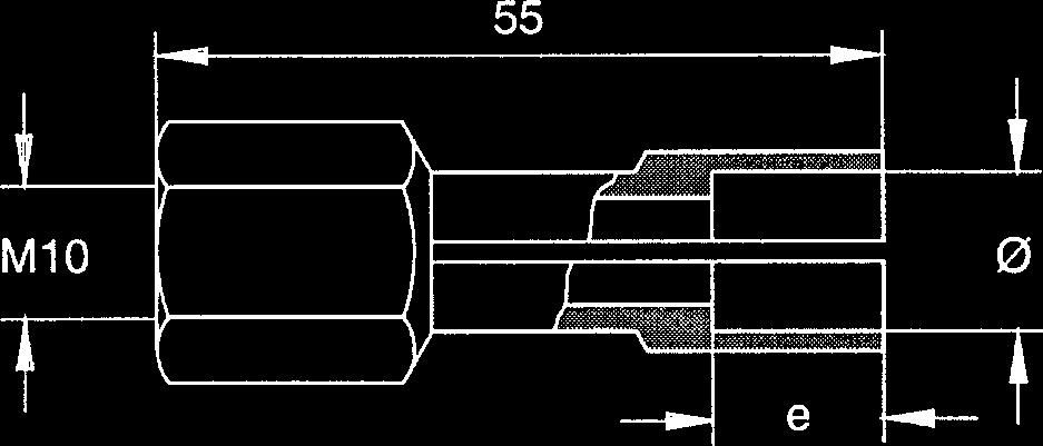
 Diameter Length M12 25-60 mm M16 30-65 mm Materials: S235 / St37.3k (4.8) / 1.4301, 1.")
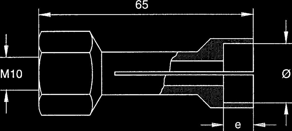
41 5 Stud Welding Procedure 5.9 Welding Elements 5.9 Welding Elements The stud welding unit must be suitable for welding the welding elements to be used. Observe the instructions in the operating manuals. Welding elements are mainly manufactured with the cold formed process. We recommend the following standard welding elements (see appendix). Use only welding elements of the same lot. Take particular care not to mix-up different lots. Slightest variations in geometry of the welding elements, especially of the ignition tip, require modified settings of the welding process. Threaded stud RD (MR) Diameter Length M mm M mm Materials: S235 / St37.3k (4.8) / , Threaded stud DD (MD) Diameter Length M mm M mm Materials: S235 / St37.3k (4.8) / , Threaded stud PD (MP) Diameter Length M mm M mm Materials: S235 / St37.3k (4.8) / , A 16 Order No. BA Issue
 Diameter Length 12 20-80 mm 16 25-80 mm")
 Diameter Length M12 20-50 mm M16")
 50-175 mm 7/8\" (22) 75-200 mm 4303 Ceramic ferrule")

42 5 Stud Welding Procedure 5.9 Welding Elements Pin UD (S) Diameter Length mm mm Materials: S235 / St37.3k (4.8) / , Pin with internal thread MI (ID) Diameter Length M mm M mm Materials: S235 / St37.3k (4.8) / , Head stud SD Diameter Length 1/2" (13) mm 5/8" (16) mm 3/4" (19) mm 7/8" (22) mm Materials: S235 / St37.3k (4.8) / , Ceramic ferrule RF for threaded stud RD Diameter Materials: S235 / St37.3k (4.8) / , A 16 Order No. BA Issue
 / 1.")

43 5 Stud Welding Procedure 5.9 Welding Elements - Ceramic ferrule PF for threaded stud PD - Ceramic ferrule UF for pins UD, MI Diameter Materials: S235 / St37.3k (4.8) / , Ceramic ferrule UF for head stud SD Diameter 1/2" 5/8" 3/4" 7/8" Materials: S235 / St37.3k (4.8) / , We look forward to consult you with view to special welding elements and other special materials. HBS Bolzenschweiss-Systeme GmbH & Co. KG Felix-Wankel-Strasse Dachau / Germany Phone +49 (0) Fax +49 (0) post@hbs-info.com A 16 Order No. BA Issue
44 6 Switching off the Welding Gun 6.1 Temporary Switching off 6 Switching off the Welding Gun This chapter describes what you should observe when you switch off the power unit temporarily or completely. 6.1 Temporary Switching off Switch off the power unit. Unplug the control cable and the welding cable from the power unit. Protect the stud welding gun against ingress of fluids and foreign bodies. 6.2 Disposal If you shut down the installation, you can return the complete welding gun to HBS (for address see page ii). We will take care for environmentally correct material separation and disposal. 44 A 16 Order No. BA Issue
45 7 Care and Maintenance 7.1 Safety Instructions 7 Care and Maintenance This chapter shows care and maintanance of the welding gun to provide long life expectancy. 7.1 Safety Instructions Let maintenance and repair operations be carried out only by qualified personnel or by your competent service technician. Before you start any cleaning and maintenance operation with the welding gun, always switch the power unit off and disconnect control cable and welding cable from power unit. A 16 Order No. BA Issue
46 7 Care and Maintenance 7.2 Regular Maintenance Operations 7.2 Regular Maintenance Operations Any maintenance and repair operation should only be carried out by qualified personnel or by your competent service technician. You must only carry out the following service operations. Before starting welding, check welding cable and control cable for faults and damage. Threat to life! Never work with damaged cables. Use of damaged cables means risking an electrical shock. Before you start any cleaning and maintenance operation with welding gun, switch off the connected power unit and disconnect control cable and welding cable from power unit. Clean the surface of the welding gun of dirt and dust. Do not use any solvent containing cleaning agents. Solvent containing cleaning agents may damage the plastic components of the welding gun. Check the chuck from time to time. If you disclose scorching areas on the chuck, replace the chuck (see chapter 4 and 5). Before you start working, check the bellows at the front end of the welding gun for possible damage and if properly installed. Never work with damaged or improperly installed bellows. This may significantly affect life expectancy of your welding gun. There are some markings (type and adjustment guides) placed at the welding gun. Take care that markings remain clearly visible. Replace illegible or damaged markings. 46 A 16 Order No. BA Issue
47 8 Appendix 8.1 Technical Data 8 Appendix In the appendix, there is information of interest regarding technical data, spare part lists, accessories, standards etc. 8.1 Technical Data Stud Welding Gun A 16 (damped) for ARC stud welding according to current standards Welding range Dia. 3 to 16 mm (Dia. #4 to 5/8'') Stud length 10 to 270 mm (0.39" to 10.63") depending on tripod Stud material Mild steel or stainless steel Stud type Any type or shape (special chucks if required) Length adjustment 6 mm (0.24'') automatic Stroke Adjustment range 0.16'' (4 mm), (0.01'' (0.25 mm) steps, arresting) Damping Adjustable oildamper Welding cable 4.85 m, 50 mm² (15.91', 1/0) Insulation class Workplace noise level Operational and storage conditions Dimension L x W x H Weight IP 20 (protect against humidity) Up to 90 db (A) may occur during welding According to current standards 260 x 74 x 220 mm (10.24'' x 2.95'' x 8.66'') without cable, with foot piece 2 kg (4.41 lbs) without cable A 16 Order No. BA Issue
48 8 Appendix 8.2 Spare Parts 8.2 Spare Parts Spare part list welding gun type A 16, ceramic ( ) When ordering spare parts, please indicate order number and type of welding gun. The type is to be found at the housing. Pos. Quantity Order No. Description Basic shell Cover shell Sticker Bearing support, complete Guide tube, complete Adjusting mechanism, complete Piston complete Length compensation, complete Pressure spring Cap, complete Plunging damper Lift damper Stativ support, complete Bellows Cylindrical pin 4 x Pressure spring welding Screw Plasfast 4 x 12 / Torx Screw Plasfast 4 x 16 / cross-recess Double nipple O-ring 7 x Connecting line complete Locking washer Screw M4 x Connection cable, complete Piston adaptor Screw M3 x Screw M6 x Spacer ring Adjustment screw Screw M5 x Cap shock absorber Screw Plasfast 4 x 20 / cross-recess 48 A 16 Order No. BA Issue
")
49 8 Appendix 8.2 Spare Parts Welding gun type A 16, ceramic ( ) A 16 Order No. BA Issue


50 8 Appendix 8.3 Accessories 8.3 Accessories When ordering accessories, please indicate order number and type of welding gun. for Description Threaded studs, Chuck sleeves with internal thread and pins Ø 6 mm Ø 8 mm Ø 8 mm Ø 10 mm Ø 10 mm Ø 12 mm Ø 16 mm e 7 mm e 4 mm e 9 mm e 4 mm e 11 mm e 13 mm e 13 mm larger Ø on request Concrete anchors and head studs 1 /4" / Ø 12,5 mm e 6 mm 3 /8" / Ø 19 mm e 9 mm 1 /2" / Ø 25 mm e 8 mm 5 /8" / Ø 32 mm e 12 mm 50 A 16 Order No. BA Issue


51 8 Appendix 8.3 Accessories for Description Threaded studs, Chuck ceramic ferrules sleeves with internal thread and pins From Ø 16 mm upwards other foot plate required for stud-ø Ø 6 mm Ø 8 mm Ø 10 mm Ø 12 mm Ø 16 mm larger Ø on request Concrete anchor and head stud 1 /4" Ø 6 mm 3 /8" Ø 10 mm 1 /2" Ø 13 mm 5 /8" Ø 16 mm A 16 (ceramic) Ceramic tripod complete PSC2 Stud Ø 4-12 mm Ø 22 mm Stud Ø mm Ø 28 mm Concrete anchor from 5 /8" Ø 29 mm Concrete anchor from 5 /8" Ø 29 mm A 16 Order No. BA Issue

 Foot piece Stud Ø 4-12 mm Stud Ø 16-20 mm Stud Ø 5 /8\" - 7 /8\" Ø 22 mm Ø 28 mm Ø 29 mm Welding with protective gas:")
52 8 Appendix 8.3 Accessories for Description A 16 (Ceramic) Foot piece Stud Ø 4-12 mm Stud Ø mm Stud Ø 5 /8" - 7 /8" Ø 22 mm Ø 28 mm Ø 29 mm Welding with protective gas: Threaded studs, Chuck threaded bushes and pins Ø 4 mm Ø 5 mm Ø 6 mm Ø 7,1 mm Ø 8 mm Ø 10 mm Ø 12 mm Ø 16 mm e 5 mm e 4 mm e 7 mm e 9 mm e 9 mm e 11 mm e 13 mm e 7 mm 52 A 16 Order No. BA Issue
ARC 500. Power Unit North America A. Operating Manual
 ARC 500 Power Unit North America 93-16-0401A Operating Manual 2010 Customer Service in Germany: HBS Bolzenschweiss-Systeme GmbH & Co. KG Felix-Wankel-Strasse 18 85221 Dachau / Germany Phone +49 (0) 8131
IT Operating Manual. Power Unit
 IT 2002 Power Unit 93-66-2201 Operating Manual Customer Service in Germany: HBS Bolzenschweiss-Systeme GmbH & Co. KG Felix-Wankel-Strasse 18 85221 Dachau / Germany Phone +49 (0) 8131 511-0 Fax +49 (0)
IT Power Unit Ceramic/Gas Version Operating Manual
 IT 1002 Power Unit Ceramic/Gas Version 93-66-1202 Operating Manual Customer Service in Germany: HBS Bolzenschweiss-Systeme GmbH & Co. KG Felix-Wankel-Strasse 18 85221 Dachau / Germany Phone +49 (0) 8131
Cutlass Fasteners, Inc. 83 Vermont Ave., Unit 6, Warwick, RI Tel: (401) Fax: (401) cutlass-studwelding.com
 Fax: (401) cutlass-studwelding.com") MODEL : PHM-12 ARC WELD GUN PART NO. : PHM-12 (PHM-12-RS) SERIAL NO. : PLEASE READ THIS OPERATION AND MAINTENANCE MANUAL CAREFULLY BEFORE USING YOUR NEW CUTLASS STUD WELDER. COPYRIGHT CFI 2009 email: sales@
MODEL : PHM-12 ARC WELD GUN PART NO. : PHM-12 (PHM-12-RS) SERIAL NO. : PLEASE READ THIS OPERATION AND MAINTENANCE MANUAL CAREFULLY BEFORE USING YOUR NEW CUTLASS STUD WELDER. COPYRIGHT CFI 2009 email: sales@
Operate Manual. DA-1600i Stud Welding Machine. DA-2000i Stud Welding Machine. DA-2500i Stud Welding Machine
 DA-1600i Stud Welding Machine DA-2000i Stud Welding Machine DA-2500i Stud Welding Machine Operate Manual KENT STUD WELDING CO., LTD 1 Content 1. Preface------------------------------------------------------------------------------
Industrial flue gas probes. Instruction manual
 Industrial flue gas probes Instruction manual 2 1 Contents 1 Contents 1 Contents... 3 2 Safety and the environment... 4 2.1. About this document... 4 2.2. Ensure safety... 4 2.3. Protecting the environment...
WE01A GMA (MIG) Plug Weld
 Plug Weld") Uniform Procedures For Collision Repair WE01A GMA (MIG) Plug Weld 1. Description This procedure describes methods for making and evaluating gas metal arc (GMA) plug welds (MIG plug welds) on all types
Uniform Procedures For Collision Repair WE01A GMA (MIG) Plug Weld 1. Description This procedure describes methods for making and evaluating gas metal arc (GMA) plug welds (MIG plug welds) on all types
ARC WELD STUDS & ARC STUD WELDING EQUIPEMENT
 ARC WELD STUDS & ARC STUD WELDING EQUIPEMENT ARC STUDS GENERAL INFORMATION THE ARC STUDWELDING PROCESS ARC Studwelding is generally used to weld larger diameter studs to thick base metals. ARC Studs may
FW66 FORESTRY WINCH FW66. Owner s Manual 19/02/2016
 FW66 FORESTRY WINCH FW66 19/02/2016 Owner s Manual TABLE OF CONTENTS INTRODUCTION ---------------------------------------------------------------------------------- 2 INTENDED USE -----------------------------------------------------------------------------------
AHP WELDS USER MANUAL
 AHP WELDS USER MANUAL Alpha-TIG200X (version III) Contents 1. Safety... 2 2. About your AlphaTig 200X... 3 3. Parameters... 4 4. Panel Index... 5 5. Setup Instructions... 6 6. Operating Instructions...
PE45 AMAZON MONKEY BARS OWNER'S MANUAL
 PE45 AMAZON MONKEY BARS OWNER'S MANUAL WARNING! The disassembled product may contain small parts which pose a choking hazard to children under 3. IMPORTANT: This product may contain sharp points and small
Conergy SolarFamulus II
 Conergy SolarFamulus II Installation manual www.conergy.com Table of Contents Table of Contents SolarFamulus II for universal use on flat roofs 1 Introduction 1 1.1 Short description 1 1.2 Intended use
LOAD RAMP 1000 LB. CAPACITY
 LOAD RAMP 1000 LB. CAPACITY 55424 ASSEMBLY AND OPERATING INSTRUCTIONS Safely roll Dirt Bikes and more into your Pickup! 3491 Mission Oaks Blvd., Camarillo, CA 93011 Visit our Web site at http://www.harborfreight.com
DISSTON WELDING PRODUCTS TIG/MMA-160/180/200/250D. Welding Machines
 DISSTON WELDING PRODUCTS TIG/MMA-160/180/200/250D Welding Machines FOR SAFE OPERATION: Keep the work area clean. Cluttered work areas invite injuries (indoor and outdoor). Consider the work environment.
IMAGE INDUSTRIES INC. STUD WELDING CATALOG. Attachment Systems Cold Formed Parts Assemblies
 IMAGE INDUSTRIES INC. STUD WELDING CATALOG Attachment Systems Cold Formed Parts Assemblies ! WARNING FAILURE OR IMPROPER SELECTION OR IMPROPER USE OF THE PRODUCTS AND/OR SYSTEMS DESCRIBED IN THIS CATALOG
Manual YJXB-3 STEEL & CASTING WELDER
 Manual YJXB-3 STEEL & CASTING WELDER General Description YJXB-3 Steel & Casting Repair Welder helps to reduce cost and improve production quality in many areas, such as plastic moulds, casting, and any
Given a functional welder, instruction and demonstration of use, each employee will be able to:
 I. Competencies Given a functional welder, instruction and demonstration of use, each employee will be able to: A. Identify the major parts of the arc welder. B. Pass a written test of safety and operating
FAST SPOTTER WT-FS-5.0
 . FAST SPOTTER WT-FS-5.0 Installation, Operating and Maintenance Manual WELDING TECHNOLOGIES www.weldingnet.com 1365 Horseshoe Dr., Blue Bell, PA 19422 Phone: 610-278-9325 Fax: 610-278-9325 Toll Free Number:
WE11S GMA (MIG) Fillet Weld
 Fillet Weld") Uniform Procedures For Collision Repair WE11S GMA (MIG) Fillet Weld 1. Description This procedure describes methods for making and inspecting GMA (MIG) fillet welds on automotive steel. 2. Purpose The
Uniform Procedures For Collision Repair WE11S GMA (MIG) Fillet Weld 1. Description This procedure describes methods for making and inspecting GMA (MIG) fillet welds on automotive steel. 2. Purpose The
AC/DC MULTI-200P AC/DC MULTI-220P
 THANKS FOR PURCHASING OUR PRODUCT AC/DC MULTI-200P AC/DC MULTI-220P DC INVERTER AC TIG/DC TIG/DC MMA/CUT 4 IN 1 MACHINE OPERATION INSTRUCTIONS SAFETY PRECAUTIONS Follow these precautions carefully. Improper
AP5K-C Precision AC Double-Pulse Spot Welding Machine User s Manual Shenzhen Will-Best Electronics Co., Ltd
 AP5K-C Precision AC Double-Pulse Spot Welding Machine User s Manual Shenzhen Will-Best Electronics Co., Ltd 1 Content 1. Introduction...3 1.1 Functions...3 1.2 Units of AP5K-C...4 2. The Initial Installation
Shackles. Applications. Range. Design. CAD drawings. Finish
 Applications Shackles are used in lifting and static systems as removable links to connect (steel) wire rope, chain and other fittings. Screw pin shackles are used mainly for non-permanent applications.
CAPACITOR DISCHARGE (CD) WELD STUDS & STUD WELDING EQUIPMENT
 WELD STUDS & STUD WELDING EQUIPMENT") CAPACITOR DISCHARGE (CD) WELD STUDS & STUD WELDING EQUIPMENT THE WELDING PROCESS THE CAPACITOR DISCHARGE (CD) STUDWELDING PROCESS CD Studwelding is generally used to weld smaller diameter studs to thin
CAPACITOR DISCHARGE (CD) WELD STUDS & STUD WELDING EQUIPMENT THE WELDING PROCESS THE CAPACITOR DISCHARGE (CD) STUDWELDING PROCESS CD Studwelding is generally used to weld smaller diameter studs to thin
7 PIECE TUBE FLARING KIT
 7 PIECE TUBE FLARING KIT Model 5969 Set up And Operating Instructions Diagrams within this manual may not be drawn proportionally. Due to continuing improvements, actual product may differ slightly from
Operating Instructions
 Operating Instructions A-2600 SERIES AWWA SWING CHECK VALVE 500 West Eldorado Street Decatur, Illinois 62522 www.muellercompany.com! WARNING! 1. Read and follow all pertinent instructions carefully. Proper
UL, KUL, WG-KUL, ARK, ARK-1
 Installation manual GB/en Non-return dampers Types UL, KUL, WG-KUL, ARK, ARK-1 TROX GmbH Heinrich-Trox-Platz 47504 Neukirchen-Vluyn Germany Phone: +49 (0) 2845 2020 Fax: +49 (0) 2845 202265 E-mail: trox@trox.de
Turbocharger / TPL-C Original assembly instructions English
 Assembly Instructions Turbocharger / TPL-C Original assembly instructions English This document is valid for the TPL-C series: TPL79-C Purpose The assembly instructions explain how the ABB turbocharger
Owner s Manual & Safety Instructions
 Owner s Manual & Safety Instructions Save This Manual Keep this manual for the safety warnings and precautions, assembly, operating, inspection, maintenance and cleaning procedures. Write the product s
YJHB-2 Micro Repair Welder
 MANUAL YJHB-2 Micro Repair Welder We appreciate that you have chosen our YJHB-2 Micro Repair Welder. Customer satisfaction is our priority. We strive to provide the most efficient machine, and a good after-sales
Notes Changed note Date. 1 (A) Changed template 09 / 07 / 2008
 Changed template 09 / 07 / 2008") Revisions Notes Changed note Date 1 (A) Changed template 09 / 07 / 2008 2 Changed template. Clause 12.5.4.1 hot-rolled steel added. Clause 12.5.4.2, 12.5.2.4, 12.5.3.4, 12.5.4.4, 12.5.5.4, 12.5.6.4, 12.5.7.4
Revisions Notes Changed note Date 1 (A) Changed template 09 / 07 / 2008 2 Changed template. Clause 12.5.4.1 hot-rolled steel added. Clause 12.5.4.2, 12.5.2.4, 12.5.3.4, 12.5.4.4, 12.5.5.4, 12.5.6.4, 12.5.7.4
Eastwood Spot Weld Gun Instructions
 263 Shoemaker Rd. Pottstown, PA 19464 US and Canada: 1-800-345-1178 Outside US: 610-718-8335 Fax: 610-323-6268 www.eastwood.com Instruction Manual Part #19089Q Rev. 3/08 Eastwood Spot Weld Gun Instructions
Manual Rotary Heat Sealers. Type: F108TX. List of content : Introduction 2. General description 3. Application 4. Safety precautions 5
 Manual Rotary Heat Sealers Type: F108TX List of content : Page: Introduction 2 General description 3 Application 4 Safety precautions 5 Transport and storage 6 Installation 7 First Set-up 8 Connection
Item # ARC200i WELDER ASSEMBLY & OPERATING INSTRUCTIONS
 Item #20484 ARC200i WELDER ASSEMBLY & OPERATING INSTRUCTIONS The EASTWOOD ARC200I WELDER provides a convenient method of performing stick welding carbon steel or stainless steel. Inverter Technology provides
Protective Capony RTC-16
 Protective Capony RTC-16 ASSEMBLY AND OPERATION MANUAL Protective Canopy RTC-16 Assembly and Operation Manual CONTENT: 1 APPLICATION...3 2 OPERATION CONDITIONS...3 3 TECHNICAL SPECIFICATIONS...3 4 DELIVERY
SMAW. Shielded metal arc welding (SMAW) is commonly referred to as stick welding
 is commonly referred to as stick welding") SMAW EQUIPMENT SMAW Shielded metal arc welding (SMAW) is commonly referred to as stick welding An electric arc between the stick electrode and the base metal creates heat. Heat melts the base metal and
SMAW EQUIPMENT SMAW Shielded metal arc welding (SMAW) is commonly referred to as stick welding An electric arc between the stick electrode and the base metal creates heat. Heat melts the base metal and
PMA 31-G. English. Printed: Doc-Nr: PUB / / 000 / 00
 PMA 31-G English 1 Information about the documentation 1.1 About this documentation Read this documentation before initial operation or use. This is a prerequisite for safe, trouble-free handling and
Owner s Manual & Safety Instructions
 Owner s Manual & Safety Instructions Save This Manual Keep this manual for the safety warnings and precautions, assembly, operating, inspection, maintenance and cleaning procedures. Write the product s
4 rotary milling table
 4 rotary milling table Model 97208 Set up And Operating Instructions Diagrams within this manual may not be drawn proportionally. Due to continuing improvements, actual product may differ slightly from
OPERATOR S SAFETY MANUAL
 June 2011 OPERATOR S SAFETY MANUAL Sumner Pipe Jacks www.sumner.com 7514 Alabonson Road Houston, TX 77088 U.S.A ph: 281.999.6900 fax: 281.999.6966 470 Collier MacMillan Drive Unit 2 & 3 Cambridge, ON N1R
Thermocouples. Operating and Maintenance Manual English. Thermocouples
 Thermocouples Operating and Maintenance Manual English Seite 1 / 8 Operating and Maintenance Manual Thermocouples Table of Contents 1 General Information 3 2 Functionality 4 2.1 Thermo Lines and Compensating
Item #20295 ARC 80 WELDER ASSEMBLY & OPERATING INSTRUCTIONS
 Item #20295 ARC 80 WELDER ASSEMBLY & OPERATING INSTRUCTIONS The Eastwood Arc 80 provides a convenient method of performing arc or stick welding carbon steel or stainless steel. Inverter Technology provides
Z5377 E6 Swivel bracket Mounting instructions (1.2 EN)
") Z5377 E6 Swivel bracket Mounting instructions (1.2 EN) Contents 1. Product description and scope of supply...3 2. Intended use...3 3. Safety precautions...4 4. Assembly...4 5. Operation...4 6. Maintenance
Z5377 E6 Swivel bracket Mounting instructions (1.2 EN) Contents 1. Product description and scope of supply...3 2. Intended use...3 3. Safety precautions...4 4. Assembly...4 5. Operation...4 6. Maintenance
DJ Switch 10F V2 ORDERCODE 50365
 DJ Switch 10F V2 ORDERCODE 5035 Congratulations! You have bought a great, innovative product from Showtec. The Showtec DJ Switch brings excitement to any venue. Whether you want simple plug-&-play action
ST XX28 Stainless Steel Thermostatically Controlled Electric Model
 DIXONS SURGICAL INSTRUMENTS LTD, 1 ROMAN COURT HURRICANE WAY, WICKFORD BUSINESS PARK WICKFORD, ESSEX, SS11 8YB, UK TEL: +44 (0)1268 764614 - FAX: +44 (0)1268 764615 EMAIL: info@dixons-uk.com - WEB: http://www.dixons-uk.com
1. Gas Welding C k. br-er1-02.cdr ISF 2002
 1. Gas Welding 3propane 1. Gas Welding 7 Although the oxy- process has been introduced long time ago it is still applied for its flexibility and mobility. Equipment for oxy welding consists of just a few
Operator s Manual for Morse Heavy-Duty Kontrol-Karrier with 3-Piece Drum Holder
 CONTENTS Page Receiving Procedures.................... 1 Warranty............................. 1 Safety Information..................... 1-2 Machine Description................... 3 Operating Instructions....................
INSPECTION OF FIELD WELDING
 INSPECTION OF FIELD WELDING Objective Types of Projects Involving Welding Common Welding Terms & Symbols Welder Qualifications Common Welding Requirements Welding Inspection Types of Projects Involving
Roughneck Mesh Slings
 Roughneck Slings Roughneck Slings Roughneck WIRE MESH SLINGS Specialty Slings with Particular Properties and Uses Widely used in metalworking shops and steel warehouses where loads are abrasive, hot or
RAUPEX SPEED SYSTEM Installation Guide
 RAUPEX SPEED SYSTEM Installation Guide INFORMATION AND SAFETY INSTRUCTIONS Validity The installation instructions are valid for North America. Other applicable technical information - Floor heating/cooling
Instruction Manual HT 24 BM-D2400 Homogenizer
 Instruction Manual HT 24 BM-D2400 Homogenizer Foreword Thank you for purchasing a HT 24 Homogenizer. This manual contains instructions for the proper operation and care of this instrument. Please read
Good Husband Brand Remote Lighting Lifter
 Good Husband Brand Remote Lighting Lifter National Patent Number:200520069085.5 200520075680.X 200520075677.8 200520075679.7 International Patent Number: PCT/CN2006/000409 Product Standard: Q/QABC002-2009
2-finger angular gripper SGB 32-50
 www.comoso.com Translation of the original manual 2-finger angular gripper SGB 32-50 Assembly and Operating Manual Superior Clamping and Gripping Imprint www.comoso.com Imprint Copyright: This manual remains
Operating Instructions Plasma generator PG31
 Operating Instructions Plasma generator PG31 BA-PG31_EN / F0298601 We are pleased that you decided on a brand device from relyon plasma GmbH and thank you for the trust you have placed in our company.
WELDING Topic and Contents Hours Marks
 Topic and Contents Hours Marks 3.1 Introduction 04 Marks Classification and selection of welding process. Working principle of Gas welding and types of flames. 3.2 Arc welding process 08 Marks Metal arc,
Installation, Operation & Maintenance Manual
 Original Instructions Installation, Operation & Maintenance Manual Sentry SC Sample Cutter Automatic Sampling Accessories S-AS-IOM-00530-0 02-18 Table of Contents Safety Information... 4 General Safety
HANGERS AND SUPPORTS FOR HVAC PIPING AND EQUIPMENT SECTION HANGERS AND SUPPORTS FOR HVAC PIPING AND EQUIPMENT
 13686.00 HANGERS AND SUPPORTS FOR HVAC PIPING AND EQUIPMENT 230529-1 SECTION 230529 - HANGERS AND SUPPORTS FOR HVAC PIPING AND EQUIPMENT 1.1 SUMMARY A. Section Includes: 1. Metal pipe hangers and supports.
SPEEDTEC 180C & 200C
 SPEEDTEC 180C & 200C OPERATOR S MANUAL IM3039 04/2016 REV07 ENGLISH Lincoln Electric Bester Sp. z o.o. ul. Jana III Sobieskiego 19A, 58-263 Bielawa, Poland www.lincolnelectric.eu Declaration of conformity
Installation, Operation & Maintenance Manual
 Original Instructions Installation, Operation & Maintenance Manual Sentry IC Indexing Cabinet Automatic Sampling Accessories S-AS-IOM-00462-2 11-17 Do not install, maintain, or operate this equipment without
!!!! WARNING!!!! WELDING FUMES AND GASES CAN BE DANGEROUS TO YOUR HEALTH.
 CAREFULLY!!!! WARNING!!!! CAREFULLY WELDING FUMES AND GASES CAN BE DANGEROUS TO YOUR HEALTH. BEFORE USING THIS PRODUCT THE WELDER (END-USER) MUST READ AND UNDERSTAND THE COMPLETE PRODUCT WARNING LABEL
Z5352 E12 Flying bracket Mounting instructions (1.0 EN)
") Z5352 E12 Flying bracket Mounting instructions (1.0 EN) Contents 1. Product description and scope of supply...3 2. Intended use...3 3. Safety precautions...4 4. Assembly...4 5. Operation...4 6. Maintenance
Z5352 E12 Flying bracket Mounting instructions (1.0 EN) Contents 1. Product description and scope of supply...3 2. Intended use...3 3. Safety precautions...4 4. Assembly...4 5. Operation...4 6. Maintenance
BakeMax Dough Mini Moulder BMMDM02
 BakeMax Dough Mini Moulder BMMDM02 2 Instruction Manual 1. Preface ------------------------------------------- P2 2. Machine Introduction -------------------------------- P2 3. Machine Specification and
Z5033 E3 Ball joint adapter Mounting instructions
 Z5033 E3 Ball joint adapter Mounting instructions Z5033 E3 Ball joint adapter References in the manual This refers to a potentially dangerous situation which may lead to personal injury. This refers to
Technical Service. INSTALLATION INSTRUCTIONS FOR TARAFLEX SPORT PRODUCTS over Gypsum base Products. This document refers to the following products:
 INSTALLATION INSTRUCTIONS FOR TARAFLEX SPORT PRODUCTS over Gypsum base Products This document refers to the following products: Product Width Width Ft. Installation direction Seams treatment Taraflex Surface
FIVE STAR PRODUCTS, INC. (800)
") FIVE STAR PRODUCTS, INC. www.fivestarproducts.com (800) 243-2206 Page 1 of 11 DESIGN-A-SPEC GUIDELINES FIVE STAR RS ANCHOR GEL CONTENTS PART A - GENERAL CONDITIONS PART B - MATERIAL SPECIFICATIONS PART
FIVE STAR PRODUCTS, INC. www.fivestarproducts.com (800) 243-2206 Page 1 of 11 DESIGN-A-SPEC GUIDELINES FIVE STAR RS ANCHOR GEL CONTENTS PART A - GENERAL CONDITIONS PART B - MATERIAL SPECIFICATIONS PART
1 TON PORTABLE GANTRY CRANE Model LB. PORTABLE GANTRY CRANE Model 94831
 1 TON PORTABLE GANTRY CRANE Model 94884 660 LB. PORTABLE GANTRY CRANE Model 94831 ASSEMBLY AND OPERATING INSTRUCTIONS Due to continuing improvements, actual products may differ slightly from the products
Linear Indexing System. Type LF. Original Operating Instructions
 Linear Indexing System Type LF Original Operating Instructions LF Type Linear Indexing System Contents Contents Contents... 3 1 Overview, brief description... 5 2 About these Operating Instructions...
XSTi Standby UPS. 400VA, 600VA, 800VA Models. User & Installation Manual
 XSTi Standby UPS 400VA, 600VA, 800VA Models User & Installation Manual www.xpcc.com 2015. All rights reserved. (Rev 12/14/15) Table of Contents Package Contents... 3 Product Introduction... 3 Product Overview...
ARC STUD WELDING SYSTEMS
 ARC STUD WELDING SYSTEMS ARE complete stud welding systems which weld ARC studs using the ARC stud welding process. CONSIST OF the following items: An ARC stud welding power supply with built-in timer/control
GAS METAL ARC WELDING (GMAW)
") GAS METAL ARC WELDING (GMAW) INTRODUCTION Gas Metal Arc Welding (GMAW) is also called Metal Inert Gas (MIG) arc welding. It uses consumable metallic electrode. There are other gas shielded arc welding
GAS METAL ARC WELDING (GMAW) INTRODUCTION Gas Metal Arc Welding (GMAW) is also called Metal Inert Gas (MIG) arc welding. It uses consumable metallic electrode. There are other gas shielded arc welding
PVC Project Assembly Guide a FORMUFIT field manual
 PVC Project Assembly Guide a FORMUFIT field manual www.formufit.com 1 PVC Project Assembly Guide 1 Welcome. This guide is designed to be friendly, knowledgable and to provide options for different people
Owner s Manual & Safety Instructions
 Owner s Manual & Safety Instructions Save This Manual Keep this manual for the safety warnings and precautions, assembly, operating, inspection, maintenance and cleaning procedures. Write the product s
HEAVY DUTY WELDING CART
 HEAVY DUTY WELDING CART 43615 ASSEMBLY AND OPERATING INSTRUCTIONS 3491 Mission Oaks Blvd., Camarillo, CA 93011 Visit our Web site at http://www.harborfreight.com Copyright 2000 by Harbor Freight Tools.
Stud Welding Procedures Training. Presented By Dan Beigel in cooperation with Texas Stud Weld and UFS QC.
 Stud Welding Procedures Training Presented By Dan Beigel in cooperation with Texas Stud Weld and UFS QC. OVERVIEW Define - What is Stud Welding? Purpose - Why do we need Stud Welding? Training? Safety
ST 19 Aluminium Manually Controlled Electric Model
 ST 19 Aluminium Manually Controlled Electric Model Operators Manual Issue 5 For correct operation of this autoclave it is essential that the chamber be filled with water up to the height of the studs before
ifix INSTALLATION MANUAL PV flat roof installation system Version
 ifix PV flat roof installation system INSTALLATION MANUAL Version 2012-09-06 ifix Installation Manual Version 2012-09-06 Seite 1 Table of contents Table of contents... 1 Special characteristics of ifix...
the P.R. Skate, LLC Pallet Rack Moving System Product Manual
 the P.R. Skate, LLC Pallet Rack Moving System Product Manual the P.R. Skate, LLC Product Manual In this manual we will cover both normal operation of the P.R. Skate moving system and safety issues that
B. Polyethylene samples shall be submitted for Owner approval of color and quality.
 Glass Rail ENGINEERED DASHERBOARD SPECIFICATIONS PART 1 - GENERAL 1.01 PROJECT SCOPE A. Contractor shall furnish and install one complete set of steel framed dasherboards as indicated on the drawings and
Section 906. STRUCTURAL STEEL
 906.01 Section 906. STRUCTURAL STEEL 906.01. General Requirements. Finished rolled shapes must be free from imperfections that affect strength and durability in accordance with ASTM A 6. Rolled shapes
SECTION HANGERS AND SUPPORTS FOR PLUMBING PIPING AND EQUIPMENT
 SECTION 220529 HANGERS AND SUPPORTS FOR PLUMBING PIPING AND EQUIPMENT PART 1 - GENERAL 1.1 RELATED DOCUMENTS A. Drawings and general provisions of the Contract, including General and Supplementary Conditions
Z5043 MAX Horizontal bracket Mounting instructions
 Z5043 MAX Horizontal bracket Mounting instructions Z5043 MAX Horizontal bracket References in the manual This refers to a potentially dangerous situation which may lead to personal injury. This refers
Nelson Stud Welding - USA. Nelson Stud Welding - NZ. Enquires: Auckland Tel: Fax: Wellington Tel: or
 Nelson Stud Welding - USA Nelson Stud Welding, founded in the USA, 75 years ago, is the leading global manufacturer and distributor of weld stud fasteners and application equipment serving a broad range
Pipe Joints. Requirements and Test Methods. VdS-Guidelines for water extinguishing systems. VdS en. VdS en : (01)
") VdS-Guidelines for water extinguishing systems VdS 2100-6en Requirements and Test Methods Reproduction prohibited even for internal use VdS 2100-6en : 2004-01 (01) Publisher and Publishing house: VdS Schadenverhütung
VdS-Guidelines for water extinguishing systems VdS 2100-6en Requirements and Test Methods Reproduction prohibited even for internal use VdS 2100-6en : 2004-01 (01) Publisher and Publishing house: VdS Schadenverhütung
SECTION REINFORCING STEEL
 SECTION REINFORCING STEEL 1. DESCRIPTION This specification shall govern the furnishing and placing of reinforcing steel, deformed and smooth, of the size and quantity designated on the plans and in accordance
TIG200 DC WELDER INSTRUCTIONS. Item #20566
 TIG200 DC WELDER INSTRUCTIONS Item #20566 TIG Welding is the most controllable, efficient and versatile method of welding many metals including steel, stainless steel and more. Your EASTWOOD TIG 200 DC
ANSI/AWS D R An American National Standard. Recommended Practices for Root Pass Welding of Pipe Without Backing
 ANSI/AWS D10.11-87R An American National Standard Recommended Practices for Root Pass Welding of Pipe Without Backing Key WordS Root pass welding, pipe, gas purging, consumable inserts, gas tungsten arc,
SECTION ALUMINUM GATES
 P.O. Box 1058 370 South Athol Rd. Athol, Massachusetts 01331 Phone: (978) 249-7924 Fax: (978) 249-3072 SECTION ALUMINUM GATES PART 1 GENERAL 1.01 SCOPE OF WORK A. The CONTRACTOR shall furnish all labor,
Universal Tilting TV Mount 32" to 60" Installation Instructions
 Universal Tilting TV Mount 32" to 60" Installation Instructions Tiltable LCD / TFT TV Wall Mount Material: 2.0mm Cold Rolled Steel Plate TV size: 32" - 60" Tilt angle: 0-15 degrees Max load capacity: 165
24 Portable Saw Mill OWNER S MANUAL
 24 Portable Saw Mill OWNER S MANUAL WARNING: Carefully read and understand all ASSEMBLY AND OPERATION INSTRUCTIONS before operating. Failure to follow the safety rules and other basic safety precautions
CIMC: Introduction to Agricultural Power and Technology
 CIMC: Introduction to Agricultural Power and Technology Unit 3- Shielded Metal Arc Welding 1. Shielded Metal Arc Welding also goes by other names. Which of the following is another term for this type of
INDUSTRIAL Arc Welder-120
 INDUSTRIAL Arc Welder-120 Model 55060 Assembly & Operating Instructions www.harborfreight.com Copyright 2005 by Harbor Freight Tools. All Rights Reserved. No portion of this manual or any artwork contained
SECTION HANGERS AND SUPPORTS FOR PLUMBING PIPING AND EQUIPMENT
 Page 220529-1 SECTION 220529 - PART 1 - GENERAL 1.1 RELATED DOCUMENTS A. Drawings and general provisions of the Contract, including General and Supplementary Conditions and Division 01 Specification Sections,
Plasma Cutting System
 Plasma System Hiocus i The All-Rounder for Marking and from 0.5 to mm with Highest Productivity Soft-Switch-Inverter made in Germany Productivity - quality - flexibility: decisive in the competition Since
NVD-40 NEAR VERTICAL DRUM LIFTER INSTRUCTION MANUAL
 VESTIL MANUFACTURING CORP. 2999 North Wayne Street, P.O. Box 507, Angola, IN 46703 Telephone: (260) 665-7586 -or- Toll Free (800) 348-0868 Fax: (260) 665-1339 www.vestilmfg.com e-mail: info@vestil.com
L505 VISUAL LEVEL INDICATOR. Dip-Tape Visual Level Indicator INSTALLATION AND OPERATIONS MANUAL
 L505 VISUAL LEVEL INDICATOR INSTALLATION AND OPERATIONS MANUAL Dip-Tape Visual Level Indicator READ THIS MANUAL PRIOR TO INSTALLATION This manual provides information on the L505 Dip-Tape Visual Level
SAFETECH 3.2K ST v1.0. User s manual. Opale-Parachutes.com. Please read this manual before first use.
 2016 v1.0 User s manual SAFETECH 3.2K ST60 Please read this manual before first use. Thank you for choosing Opale-Parachutes. This user s guide includes all the information you need to assemble and use
DT 23 DT 24 DT 32 DT 33 DT 34 DT 44
 DT 23 DT 24 DT 32 DT 33 DT 34 DT 44 Operating Manual DURATRUSS B.V. Junostraat 2 6468 EW Kerkrade The Netherlands www.duratruss.com DURATRUSS - www.duratruss.com Operating Manual Page 1 Table of Contents
2-Finger-Parallel-Gripper RH
 Translation of the original manual 2-Finger-Parallel-Gripper RH 901-940 Assembly and Operating Manual Superior Clamping and Gripping Imprint Imprint Copyright: This manual remains the copyrighted property
CM-v-3 module. GSM/GPRS/EDGE communication module for MT880 meters. Technical description
 GSM/GPRS/EDGE communication module for MT880 meters Document code: EAD 028.890.101 Version: V1.01 Language: English Date: 06.03.2015 COPYRIGHT 2011 ISKRAEMECO d.d., Merjenje in upravljanje energije. All
US PR-8. Instruction Manual. - approved
 2000-08 US GB PR-8 Instruction Manual - approved Preface You have just bought a Pro Spot PR-8. The use of microprocessor control in our vehicle body welding equipment has many benefits. It means, for example,
Fire Barrier Duct Wrap 615+
 Fire Barrier Duct Wrap 615+ Duct Wrap Fire Protection System for Commercial Kitchen Grease and Ventilation Air Ducts Product Data Batts and blankets for use in fire resistive duct assemblies see UL fire