Nasser Marafi. Alternate Floor Systems. Pro Con Structural Study of. Technical Report 2. Center & Facility Service Building
|
|
|
- Abigayle Chandler
- 6 years ago
- Views:
Transcription


1 Pro Con Structural Study of Alternate Floor Systems St. Joseph Hospital of Orange Patient Care Center & Facility Service Building Technical Report 2 Professor Andres Lepage STRUCTURAL OPTION October 26th 2007
2 Executive Summary Pro Con Structural Study of Alternate Floor Systems This report is in an investigation to alternate floor framing systems for Saint Joseph Hospital of Orange Patient Care Center & Facility Service Building. Preliminary designs were performed upon investigation of the different floor systems. Floor systems analyzed are as follows: 1. Composite Concrete on Steel Beams (Existing System) 2. Two Way Post Tensioned Slab 3. Precast Prestressed Hollow Core Slab. 4. Two Way Concrete Waffle Flat Slab System 5. Two Way Concrete Slab with Beams Comparisons were made upon analysis, factors taken under considerations include; fire rating, cost and rate of construction, floor membrane thickness, building s self weight and effect on architectural and mechanical plans. The original design of a composite concrete on steel beams floor system seems to be the best solution. Advantages like a lighter overall system with the ability to accommodate future equipment layout alterations with ease, make this system rather unique and best for a hospital building use. 2 P age
3 Table of Contents Pro Con Structural Study of Alternate Floor Systems Executive Summary... 2 Introduction... 6 Existing Structural Systems... 7 Floor Framing... 7 Columns... 8 Identification of other structural elements... 8 Typical Floor Plans nd Floor Plan... 9 Codes Codes and Referenced Standards Typical floor bay loadings Live Loads Dead Loads Composite Concrete with Steel Beams Framing System (Existing System) System Effectiveness Structural Impact Lateral Resisting System Architectural Impact Constructions Impact Summary Two Way Post Tensioned Slab System Effectiveness Structural Impact Lateral Resisting System Foundation Effects Architectural Impact Constructions Impact Summary Precast Prestressed Hallow Core Slab System Effectiveness P age
4 Structural Impact Lateral Resisting System Foundation Effects Architectural Impact Constructions Impact Summary Two Way Concrete Waffle Flat Slab System System Effectiveness Structural Impact Lateral Resisting System Foundation Effects Architectural Impact Constructions Impact Summary Two Way Concrete Slab with Beams System Effectiveness Structural Impact Lateral Resisting System Foundation Effects Architectural Impact Constructions Impact Summary Summary Comparison Chart Conclusion Appendix Composite Concrete with Steel Beams Framing System Calculations Gravity Beam check (W16x31) Gravity Girder Check (W24x68) Two Way Post Tensioned Slab Calculations Precast Prestressed Hollow Core Slab. Calculations Two Way Concrete Waffle Flat Slab System Calculations P age
5 Two Way Concrete Slab with Beams Calculation Reinforcement Diagram P age
6 Introduction Pro Con Structural Study of Alternate Floor Systems is to be built within Saint Joseph Hospital Campus serving the healthcare needs of the Orange county community in Orange, CA. The Patient Care Center is linked to the main hospital through an underground tunnel to further serve the patients needs. The patient care center consists of two towers joined together with a central courtyard. The main entrance to the lobby is connected to the adjacent hospital reception area. The Patient Care Center consists of operating rooms to expand the surgical capacity of the main hospital. Operating rooms are equipped with latest innovative technology and medical equipment. To help further serve the main hospital, the Patient Care Center also has additional room for incoming patients and rooms for patients requiring intensive care. The Patient Care Center has a central sterile plant located on the basement level with MEP equipment. The first level of the hospital consists of surgical rooms, administrative rooms and the lobby. The upper floors are separated by the central courtyard. The west side consists of patient rooms and the east side consists of intensive care units. The remaining mechanical equipment is located on the roof level. Figure 1. Computer rendering of Patient Care Center s North elevation. 6 P age
7 Existing Structural Systems Pro Con Structural Study of Alternate Floor Systems Floor Framing There are minor variations to the floor framing through the Patient Care Center. The typical floor system is a composite steel framing using lightweight concrete and a total thickness of 6¼, 3 composite deck is used with 5 long, ¾ diameter shear studs for composite action. The typical infill beam is a W16x31, 30 0 long spaced at 10 0 on center, which frame onto a W24x long. Variations from the typical floor system are based on the use of the space. Light weight concrete was used in the typical steel deck configuration to reduce shear and overturning moment during seismic events. Fig2. Typical 30 0 x30 0 bay located on Levels 2, 3 and 4 First floor The floor framing plan on the first floor differs from the rest due to different loading criterion used. Typical infill members used are W18x35 framing into W24x68 girders. Composite steel framing is used with normal weight concrete and a total thickness of 7½, 3 composite deck with 5 long, ¾ diameter shear studs. Second floor There is a central courtyard which is supported by the second floor framing system. Due to the high loading W21x111 infill beams are used which frame into W30x148. A composite steel framing system is also used with normal weight concrete and a total thickness of 9, 3 composite deck with 5 long, ¾ diameter shear studs. Roof Due to the location of air handling units on the roof, members with a higher loading capacity are required. Therefore the member sizes change to a W18x40 for beams and W24x84 for girders. A 9 composite steel system exists similar to the second floor courtyard but covered with insulation. 7 P age
8 Columns There are two columns sets per gridline intersection which are usually spliced at 5 0 from the Level 2. Typical columns sizes are W14x99 on the upper levels (Level 2 to Roof); while the lower columns are W14x145 or W14x132 depending on location and loadings. Columns existing in the brace frame are usually W14x145 except the end columns which are W14x211 on the top and W14x311 at the bottom. These columns have greater strength capacities due to the excess tension and compression they carry from the bracing system induced moment. Identification of other structural elements There are several areas in the building that were not discussed in depth in this report. These include the underground tunnel connecting to the adjacent hospital, the canopy at the building s main entrance, and the elevator machine rooms located at the roof. Other structural elements like checking the braced system connections and the foundation system where not discussed in this report but will be analyzed and justified in later reports. 8 P age

9 Typical Floor Plans 2 nd Floor Plan The figure below represents the 2nd floor plan occupant use. Loadings here are assumed to be 80 psf where patient rooms and Intensive care units exist. While at the court yard a super imposed dead load is added counting for pavements, planters and trees. The roof on the west side is designed for future planters. The third and fourth floor plans are similar but do not include the central courtyard shaded in green and roof areas shaded in blue. This report only designs the floor system at typical bays located in the patient room and intensive care unit areas. Fig3. 2 nd floor plan showing occupant use. 9 P age
10 Fig4. 2 nd floor plan showing framing plan. 10 P age
11 Codes Codes and Referenced Standards The following table shows the codes that were adopted in this report and codes that were implemented by the designer. Codes adopted by this report Codes adopted by the designer 2007 California Building Code Title 24, Part California Building Code ASCE Uniform Building Code with California amendments ACI (PCI Handbook) 02(pcaSlab & RAM Concept) 99(CRSI Handbook) 13 th Edition of the AISC Manual of Steel Construction 6 th Edition of the PCI Handbook Typical floor bay loadings Live Loads Live loads are determined in accordance with ASCE Occupancy Designer s Uniform Live load (psf) 2007 CBC Uniform Live loads (psf) Patient Rooms Operating Rooms, Laboratories Corridors Office Designer s value used for simplicity reasons. Dead Loads Refer to Appendix in Tech. 1 for dead load calculations. Material weights are taken from the ASCE 7 05 Chapter C3. LVL2 LVL3 LVL4 Concrete Topping* Steel Deck (18 Gage)* Super Imposed Partitions Total Dead Load (psf) * Dead Load refer to existing condition 11 P age
12 Composite Concrete with Steel Beams Framing System (Existing System) System Effectiveness Fig5. Typical 30 0 x30 0 bay located on Levels 2, 3 and 4 Material Properties f c = 4000 psi fy = 60,000 psi Lightweight concrete (110 pcf) Total slab thickness = 6¼ 3 18 gage steel deck ¾ diameter shear studs Design Summary I LBgirder = 4680 in 3 I LBbeam = 1200 in 3 Floor Dead Weight = 55 psf Δ midspan =.54 Floor Self weight = 54 psf Structural Impact The use of composite floor system is by making the concrete slab double counting in its existence in the floor system. The concrete slabs works in compression while the steel beams work mainly tension. This enforces both items to work best to their advantage as suppose to a girder slab where the structural steel is doing the majority of the work. This system ensures smaller member sizes to be used, greater stiffness, and does not have major cost differences with a girder slabs system. 12 P age
13 This system is capable of handling heavy loads at long column spans. The system is fairly light in comparison with concrete systems but has a fairly large total floor thickness at about 23 in mid span. Lateral Resisting System The lateral system used in conjunction with this floor system is braced frames. The floor system self weights is a key issue regarding the total building self weight which would have minimal effect on the lateral resisting system. Architectural Impact The column sizes are fairly small in comparison with concrete floor systems, therefore would not have as much effect to architectural drawings. The floor thickness is larger than a concrete system and would therefore reduce the amount of floor height. The use of braced frames was accentuated architecturally therefore this floor system would have a contribution to architectural aesthetics. Constructions Impact This is a cost effective solution, and has a fairly quick method of construction. Shoring may not be required during curing since the steel beams are sufficient to carry the dead weight of the concrete slab. Summary Advantages Fast construction Smaller columns Cost Effective Fast Construction Time Large Spans Light structure Disadvantages Thick floor membrane Heavy Sections for floor vibrations Structural Steel requires fire proofing 13 P age
14 Two Way Post Tensioned Slab Pro Con Structural Study of Alternate Floor Systems Material Properties f c = 5,000 psi f pu = 270,000 psi f y = 60,000 psi Normal weight concrete (150 pcf) Total slab thickness = 9 Shear Capital: 3 0 x3 0 x10 Reinforcement (22) Banded tendons running E gridlines (3) Strand tendons running N 3 4 See appendix for mild steel reinforcements. Design Summary Δmidspan Interior Bays 14 P age
15 Floor Self weight = 100 psf System Effectiveness Structural Impact Due to the large span a complex concrete floor system would be required to minimize the change in the architectural floor plans. A post tension floor slab allows the use of large spans, with relative small deflections and vibration control. A post tension system limits cracking due to the prestressed compression therefore water tightness is an advantage. The system is considered very light in comparison with other concrete floor systems. Punching shear controls at every column therefore drop panels or column capitals would be required or addition of stud rails shear reinf. Lateral Resisting System Shear walls or moment frames would be considered as the lateral system and would replace all braced frames. Since shear walls are already being used on the basement floor and are connected to the continuous footings, adding more shear walls on higher levels would not be a major issue. Moment frames could be used to replace the braced frames located next to the exterior glazing. One thing that would have to be looked at is the amount of openings in the interior walls. Due to the light weight structure the amount of shear walls frames would not have to increase as much. Further analysis would have to be done to determine the amount of bays required as shear walls and moment frames. Foundation Effects Due to the increase in self weight from the original design, larger foundations would be required therefore further foundation design and analysis would be required. Architectural Impact Columns sizes would need to get bigger in this floor system in comparison to using steel columns. Since most interior walls exist at grid lines their impact of column sizes would be minimal. One major advantage of using this system is the 9 structural floor thickness at mid span. This would give flexibility to the mechanical equipments running, and allow for a lower floor to floor height reducing the building total height which has the potential to have seismic advantages. Drop panels or column capitals might have the potential to become a problem with the floor plans, but since interior walls are located at most of the gridlines, they can be used to hide the drop panels or capitals. Floor penetrations after the building has been built will become a problem since any tendon that exists in that area will lose structural strength along its entire length. Constructions Impact Further research would have to be done to determine if contracting companies in the area are familiar with this kind of system. The more common the system is in the area the more economical it would be to use such system in the design. 15 P age
16 Summary Advantages Thin floor membrane No additional fire proofing Handles large loads Crack control Deflection and vibration control Disadvantages High Cost of Construction Complex construction Shear Capital or Stud Rails Floor penetration hard to deal with 16 P age
17 Precast Prestressed Hallow Core Slab. Pro Con Structural Study of Alternate Floor Systems Material Properties f c = 5000 psi f pu = 270,000 psi Normal Weight Concrete (150 pcf) Total slab thickness = 10 Hollow Core + 3 Topping Design Summary Interior Girders: 28IT36 Hollow Core 4HC S Δmidspan Hollow Core Δmidspan Girder Floor Self weight = 149 psf System Effectiveness Structural Impact Precast prestressed hollow core panels are sufficient for spanning long distances with large loads being applied. The 4 0 hollow planks do not line up evenly with the 30 0 bays therefore custom fabricated planks would be required. Lateral Resisting System Special reinforced concrete shear walls would be considered to be the main lateral resisting system; the response factor for intermediate the shear walls is 6 (R=6 for concentrically braced frames), an 17 P age
18 increase of the buildings self weight, will lead to more lateral resisting frames than the initial design. A 3 topping is required by code since the building is considered to be seismic region; the cover would provide a rigid diaphragm. Foundation Effects Due to the increase in self weight from the original design, larger foundations would be required therefore further foundation design and analysis would be required. Architectural Impact Even though the floor thickness is 13, the floor thickness at the beams is 36, which will make this system not gain any floor height due to the fact that mechanical equipment would have to run underneath the beams. Floor penetrations would be hard; a similar problem to the post tensioned slab, where any cut tendon in the plank would lose structural integrity. Therefore floor penetrations would have to be addressed locally by the structural engineer. Constructions Impact The main advantage of this floor system will be the effective time of construction. Since the precast panels are shipped in, and no form work is required the whole structure would be erected in a short matter of time. Connections are simple unlike composite steel and require minimal labor time. Summary Advantages Fast Erection Time Stiff members Disadvantages Thick floor membrane at beams 3 Diaphragm requirement adds cost Heavy floor system Floor penetrations hard to deal with 18 P age
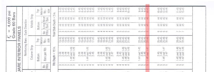
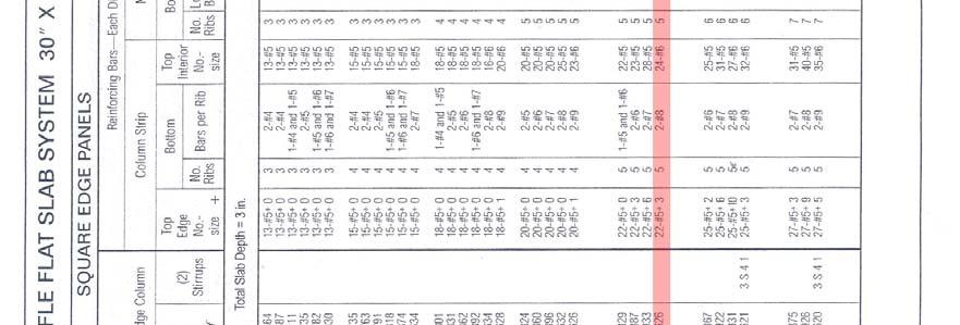
19 Two Way Concrete Waffle Flat Slab System Pro Con Structural Study of Alternate Floor Systems Material Properties f c = 4000 psi fy = 60,000 psi Normal Weight Concrete (150 pcf) Total slab thickness = 10 Ribs + 3 Slab Depth 30 x30 Voids: 6 36 Reinforcement Middle Strip (15 ) Bottom Bars: #5 Long Bar per Rib Top Bars: 18 O.C. Column Strip (15 ) Bottom Bars: (2) #7 per Rib Top Bars: 8 O.C. Design Summary Δmidspan =.259 Floor Self weight = 94 psf 19 P age
20 System Effectiveness Structural Impact This system is highly effective in this case due to the high loading and large span. The load applied to the floor system is being carried in both directions. Concrete is only poured in areas where the reinforcement exists; waffle planks void out places where concrete is not required. This layout creates ribs closely spanned running in both directions. One major advantage of this system is that a lot of concrete dead weight is reduced from the voids, and additional beams are not required in the column strips. Lateral Resisting System Shear Walls or moment frames would be considered as the main lateral resisting system. Due to the reduction of concrete being used in the slab, this reduces the total buildings dead weight which would reduce the amount of moment resisting elements required compared to the other floor systems. Moment frames would be an effective system in the floor system, with an R value of 8, and would still maintain the architectural aesthetics of the building. Foundation Effects Due to the increase in self weight from the original design, larger foundations would be required therefore further foundation design and analysis would be required. Architectural Impact This system has a thin floor thickness therefore in comparison with the composite steel system this would add additional floor height. Although slab openings would become a problem and due to the excessive openings due to mechanical equipment, the structural engineer would have to address this issue from the start. Constructions Impact Waffle slabs use expensive formwork; therefore the cost of purchasing the waffle plank would drive up construction cost. Although setting up formwork would not be considered time consuming since the same formwork shape is used over and over again. Summary Advantages Light structure in comparison with other concrete structures Stiff system Thin floor membrane Disadvantages High construction cost Difficult floor penetrations 20 P age
21 Two Way Concrete Slab with Beams Pro Con Structural Study of Alternate Floor Systems Material Properties f c = 5000 psi fy = 60,000 psi Normal Weight Concrete (150 pcf) Total slab thickness = 8.25 Reinforcement Column Strip: Top: 12 O.C. (11 0 ) Bottom: 16 O.C. Continuous Middle Strip: Top: 9 O.C. (11 0 ) Bottom: 16 O.C. Continuous Beams: Top: (5) #8 (11 0) 21 P age
22 Bottom: (2) #7 Stirrup: (15) 4, (12) 8 Refer to Appendix for calculation and reinforcement details Top reinforcement is place in the middle of the column with the total length specified Stirrup configurations start 4 from the face of the column at each side. Design Summary Δ midspan Column Strip Δ midspan Middle Strip Floor Self weight = 139 psf System Effectiveness Structural Impact Due to the large span, beams are required to run along the column grid lines. Lateral Resisting System Shear walls or moment frames would be considered as the lateral resisting system, since the floor self weight is relatively high; more lateral resisting bays would need to be considered in the final design. Foundation Effects Due to the increase in self weight from the original design, larger foundations would be required therefore further foundation analysis and design would be required. Architectural Impact Due to the impact of more shear walls, there would be the possibility of altering the floor plans interior and exterior wall openings unless moment frames were considered. Added floor height would be an advantage using this system; although the presence of beams at column gridlines would disturb the mechanical ducts path. Floor penetrations are relatively easy compared to the other systems, and could be solved easily by adding more reinforcement. Constructions Impact Cost of construction would become high due to the excessive form work and its slow rate of construction. Summary Advantages Thin slab Easy floor penetrations Disadvantages Drop Panels Required Hard formwork with beams and drop panels Heavy floor system Slow construction + high cost 22 P age
23 23 P age
24 Summary Comparison Chart Criteria Pro Con Structural Study of Alternate Floor Systems Composite Steel Post Tensioned Hollow Core Waffle Slab Two Way Slab w/ Beams Mid Bay Grid Cost $18.95 /SF $20.23 /SF $23.25 /SF $21 /SF $21.75 /SF Weight 54 psf 100 psf 149 psf 94 psf 139 psf Δ max Floor Vibrations Not an issue Not an issue Not an issue Not an issue Fire Rating Fire Proofing Spray Concrete Cover Concrete Cover+ Spray Concrete Cover Concrete Cover Floor Penetrations Moderate Hard Hard Moderate Easy Construction Time Fast Moderate Fast Moderate Slow Feasibility Possible but requires further analysis Few advantages Possible but requires further analysis Few Advantages Membranes thickness are taken both at mid span were there slab might only exist, and at the grid line where the beam and slab exists. Cost was computed using the 2006 RS Means Square Foot Cost and 2007 RS Means concrete and Masonry Cost Data, 125 psf Super Imposed Dead Load was assumed with a 30 x30 bay super structure. Post Tensioned cost was computed using flat plate floor slab with drop panels and then a stressing tendons cost was applied from 2007 RS Means concrete and Masonry Cost Data. Please note for comparison purposes all concrete design was done for normal weight concrete, but since the building is located in seismic region, the final floor system design will probably be addressed with light weight concrete to reduce lateral loads on the lateral resisting system. Applying a factor of 110(lightweight)/150(normal weight) =.73, will give you a good comparison with the composite steel system if the concrete floor system was to be considered using light weight concrete. This estimation tells us that the composite steel deck would be the lightest system. Floor vibration calculations were not taken into consideration in this report; nevertheless floor vibrations should still be looked at when the final design is complete. Therefore since deflection is inversely proportional to stiffness, and the stiffer the member the less floor vibrations would become an issue. We are able to conclude that the less the floor system deflects compared to the original design the less floor vibrations would become an issue. Fire Rating is achieved by the following methods, fire proofing spray is required by some, while all the concrete system could achieve the first rating with an extra concrete cover. Please note since 24 P age
25 the hollow core system comes prefabricated, additional fireproofing would be required by spray or custom prefabricated planks can be ordered with custom concrete cover. Refer to System Effectiveness sections in the floor system to justify floor penetrations and construction time. 25 P age
26 Conclusion Pro Con Structural Study of Alternate Floor Systems Saint Joseph Patient Care Center is in a high seismic region therefore the building self weight is a major factor when considering different floor systems. The use of steel has highly benefited the amount of lateral resisting frames in the building. And with the braced frames being used as an architectural feature, steel has incorporated itself well into the building. The use of concrete in the building will increase the building self weight; therefore increase the buildings overturning moment in the foundation due to seismic activity. The hollow core floor system should be altered so that the planks rest on the flanges of steel beams. This would have gained floor height and reduced the floor s self weight by not using huge precast beams. Overall I think this system would be highly ineffective; due to its large floor system self weight, its cost is well above the other floor systems and with the hospitals floor penetrations this system would be inefficient. The use of a two way slab with beams and drop panels could be ruled out for the same reason, its high cost and weight would make this system inefficient for a hospital in seismic region. Two systems that could be considered now would be a post tensioned slab and waffle slabs. The two systems have minor differences in cost, self weight and 3 to 5 difference in floor height. The two systems are relatively at the same stiffness judging by deflections. The post tensioned system would be highly effective at the 2 nd floor court yard and roof due to the extreme loading conditions. The courtyard and roof would have to use deeper waffle slabs which would add construction material cost. Floor penetrations are problems for both systems and would have to be addressed locally. Judging all the proposed concrete systems, the initial design using a composite steel floor system was the most effective. This can be due to many reasons; one of them is due to a low self weight compared to the concrete structures which means less seismic lateral forces that can affect the lateral force resisting system. Floor to floor height is not a major issue due to the original design being less than 80 ft. Hospitals generally go through a lot of renovations and change in mechanical and medical equipment during the life time of the buildings; therefore a system with the ease of making adjustments that affect the structural system like opening in the floor system, and heavy equipment placed in different locations would need to be addressed. A composite steel floor system offers the easiest and fastest solutions in compared to the concrete floor system when deciding to make floor openings. When heavy equipment layouts are changed steel members can be added to enhance the structural strength capacity of the floor area being changed. These reasons are probably why the structural engineer went with a composite steel floor system. 26 P age
27 Appendix Composite Concrete with Steel Beams Framing System Calculations Gravity Beam check (W16x31) Fig17. Typical 30 0 x30 0 bay located on Levels 2, 3 and 4 Computer Loadings Live Loads Dead Loads Beams with composite action, deck running perpendicular to beams w u M u V u Compute Moment Strength Capacity Σ Qn from studs Σ Qn required beff = min(0.5*span, spacing) 10 a 1.49 Y psf 79 psf f c = 3000 psi ¾ Shear 12 OC 2.22 Klf 250 ft Kips 33.3 Kips 30*17.1=516k 456K ΦMp Check Deflection I LB 1200 in 4 Δ max = l/ ft K > Mu OK Δ = 5*wL 4 /384EI.42 OK Check Deflection before composite action w u (Dead load of Concrete Deck).59 Klf I 384 in 4 Δ max =5*wL 4 /384EI Camber =.24 OK 27 P age
28 Gravity Girder Check (W24x68) Computer Loadings Beams with composite action, deck running perpendicular to beams Pu 1/3 Points) M u V u Pro Con Structural Study of Alternate Floor Systems Compute Moment Strength Capacity Σ Qn from studs Σ Qn required beff = min(0.5*span, spacing) 15 a 2.18 Y ΦMp Check Deflection I LB 4680 Δmax = l/360 1 f c = 3000 psi (60) ¾ Shear Studs 33.3 Kips 666 ft Kips 33.3 Kips 60*17.1=1026k 1000K 1270 ft K > Mu OK Δ.29 OK Check Deflection before composite action P u (Dead load of Concrete 3 rd points) 16.7 Kips I 1830 in 4 Δ.52 OK but overdesigned This analysis does not take floor vibrations into account, and since larger steel sections perform better damping, the girder might be increased in size for this reason. 28 P age
29 Two Way Post Tensioned Slab Calculations Ram Concept was used to design this floor system. Pro Con Structural Study of Alternate Floor Systems Design Criteria f c = 5000 psi fy = 60,000 psi fpu = 270,000 psi Unbounded tendons, ½ Diameter, 7 Wire Strands A = Lightweight concrete (110 pcf) Total slab thickness = 8 Super Imposed Dead Load = 32 psf Live Load = 80 psf The following are steps taken while designing the floor system using RAM concept: Slab Thickness h = L/45 = 30(12)/45 = 8 min, RAM uses 9 due to less failures Since fpu = 270 ksi, and According to ACI 18.6 the Estimated Prestress Losses = 15ksi f se = (.7)(270) ksi 15 ksi = 174 ksi (ACI ) P eff = A*f se = (0.153)(174) = 26.6 Kips/tendon Precompression Limits >124psi and <300 psi (ACI ) Preliminary Number of Tendons Required per bay running longitudinal.75% Balance of Self Weight Required W DL = (150)(9/12)(30)(.75) = 2,531 plf P = (2531)(30) 2 /8(7/12) = 488 kips, Tendon 7 from bottom of slab # Tendons = 433/26.6 = 19 Tendons P = 19(26.6)1000/(9(30)12) = 156 > 125 psi and < 300 psi, therefore ok Preliminary Number of Tendons Required per bay running latitudinal.75% Balance of Self Weight Required W DL = (150)(9/12)(30)(.75) = 2,531 plf P = (2531)(4) 2 /8(3/12) = 20 kips, Tendon 3.75 from bottom of slab and 4 # Tendons = 20/26.6 = 1 Tendons P = 1(26.6)1000/(9(4)12) = 61 > 125 psi and < 300 psi, therefore not ok, use 3 Tendons Results were placed into RAM Concept and Analysis was preformed, the numbers of tendons were then manually changed with the tendon mid span locations to obtain a balance of approximately 75% self weight. Results are as follows. 29 P age
30 Design Strips Longitudinal Pro Con Structural Study of Alternate Floor Systems Prestress force is balanced to approx. 75% self weight dead load. 30 P age
31 Design Strips Latitudinal Pro Con Structural Study of Alternate Floor Systems Prestress force is balanced to approx. 75% self weight dead load. 31 P age
32 Longitudinal Tendons Tendon location is shown and altered so that it balances to 75% self weight O.C. 32 P age
33 Latitudinal Tendons Tendon location is shown and altered so that it balances to 75% self weight. 9 Strands Exterior Band, 22 Strands Interior Band. 33 P age
34 Top Reinforcement 34 P age
35 Bottom Reinforcement 35 P age

36 Pro Con Structural Study of Alternate Floor Systems Deflection All live load deflection < L/360, therefore OK 36 P a g e
37 Punching Shear Punching shear controls at every column. There drop panels were using hand calculations. w u = 1.2[9(150)/ ] + 1.6[80] = 301 psf Assume 24 x24 Column, with d=8 (1 cover ) therefore b o = 4(24+8) = 128 V u = [ (30)(30) (24+8) 2 ] x 301= 269 Kips ΦVc = (.75)(4)(5000).5 (128)(8) = 217 kips < V u, therefore Punching shear controls Design for drop panel Depth: ΦVc = (.75)(4)(5000).5 (128)(d) = V u = 269, d= 10 Determine Drop Panel Size: V u = [ (30)(30) (x) 2 ] x 301 = ΦVc = (.75)(4)(5000).5 (12x)(10), x = 2.64 use 3 0 x3 0 Drop Panel Final Drop Panel Design, 3 0 x3 0 x10 Edge and Corner Drop Panels not design in this report. 37 P age
 = 20 (Partitions) + 12 (Super Imposed) + 80 (Live")
 = 148 > 112 psf therefore sufficient to carry the load Hollow Core Dead Weight = 93 psf +")
38 Precast Prestressed Hollow Core Slab. Calculations PCI Industry Handbook 6 th edition was used to design this floor system. Design of the hollow core floor system: Safe Super Imposed Service Loads (psf) = 20 (Partitions) + 12 (Super Imposed) + 80 (Live Loads) = 112 psf. Safe Super Imposed Service Loads (psf) = 148 > 112 psf therefore sufficient to carry the load Hollow Core Dead Weight = 93 psf + 1/12*150(1 Additional cover) = psf Design of the beams supporting the floor system as taken as follows: 38 P age
 + 105.5(Dead Load) ]* 30 = 5850 plf for Inverted Tee 39 P age")
39 Safe Super Imposed Service Loads (plf) = [112 (Super Imposed Dead load + Live Load) (Dead Load) ]* 30 = 5850 plf for Inverted Tee 39 P age
*30^4*12^3/(59119*4030508) =.")
40 Safe Super Imposed Service Loads (plf) = 5850/2 = 2925 plf for L Beam used at exterior bay. Computing Deflections: E= 57000(f c)^.5 = 4,030,508 I LBeam =59,119 in 4 Δ max = 5/384*(15x80)*30^4*12^3/(59119* ) =.09 for L Beam I Inverted Tee = 68,101 in 4 Δ max = 5/384*(30x80)*30^4*12^3/(68101* ) =.159 for Inverted Tee 40 P age
41 Two Way Concrete Waffle Flat Slab System Calculations CRSI Design Handbook 2002 is used to design waffle flat slab system. Factored Super Imposed Load (psf) = 1.4(12(Super Imposed) + 20(Partitions)) (80 (Live Load)) = 181 psf Using Waffle Flat Slab System 30 x 30 Voids: 6 Pg Total Depth = 13, Rib Depth = 10, Total Slab Depth = 3 Concrete Volume per SF=.624 CF/SF Gamma f =.626 M edge = 255 ft kips + M bot = 604 ft kips M int = 686 ft kips w udeadload = 1.4(.624)(150) =131 psfwu w u = = 312 psf V u = 312 (30*30/2) = 140 kips M o = ( )/ = kips ft.3m o = 335 kips ft Shear Check: Using a 24 x24 Column size, 13 Slab table 11 4 gives us: C ab = 9.31 A c = 1338 J c = 115,395 Vu = 140,000/(0.85*1338) (335)(12000)(9.31)/.85(115,395) = = 362 psi 4(4000)^.5 = 252 < 362 < 7(4000)^.5 = 379 therefore OK Deflection Check: Pg 11 4 Δ max = kwl 4 /Ect 3 e = *80*(30)^4*12^2/(3,500,000*10.18^3) = Design Summary: Interior Bay Col. Strip: Top: 22 #6 Therefore 6 O.C. Bottom: 2 # 7 Bars per Rib Middle Strip: Top: 10 #5 therefore 18 O.C. Bottom: #5 Long Bar and #6 Short Bar 41 P age


42 42 P age
43 Two Way Concrete Slab with Beams Calculation The design of this floor system was done using pcaslab. Additional computer analysis output is available upon request. Design Criteria f c = 5,000 psi Normal Weight Concrete (150pcf) fy = 60,000 psi Typical 30 0 x30 x0 Bay Super Imposed DL = 32 psf LL = 80 psf Computing Min. Floor thickness based on 30 x30 bay with 24 x24 Columns. h= 28(12)(.8+60,000/200,000)/(36+9(1)) = use 8.25 To obtain this slab thickness, α m = 2 is required. I slab = 30(12)8.25^3/12 = 16,845 in 4 Maintain aspect ratio of b=2/3h, α m = 2 = EI slab /EI beam, Assume Exterior Bay for Conservative Thickness I beam = (1.5)(2)(2/3h*h*h^3/12) = (16,845), solving for h = 17.8 use 18 and b = 12 Using pcaslab, the following is the design output. The following structure was modeling into pcaslab, although the interior bay was only analyzed in this report. 43 P age
44 Reinforcement Diagram Beam Reinforcement Middle Strip Reinforcement 44 P age
45 Column Strip Reinforcement Pro Con Structural Study of Alternate Floor Systems Deflections (in) All deflections < L/360 = 1 therefore OK Frame Column Strip Middle Strip Dead Live Total Dead Live Total Dead Live Total P age


46 Shear Capacity Shear Capacity is sufficient at d/2 from column face. Pro Con Structural Study of Alternate Floor Systems 46 P age


47 Moment Capacity The moment capacity is sufficient for the loading therefore the reinforcement is effective. 47 P age
THE FORENSIC MEDICAL CENTER
 THE FORENSIC MEDICAL CENTER Image courtesy of Gaudreau, Inc. TECHNICAL REPORT #2 OCTOBER 26, 2007 KEENAN YOHE STRUCTURAL OPTION DR. MEMARI FACULTY ADVISOR EXECUTIVE SUMMARY Image courtesy of Gaudreau,
Table of Contents.2. Introduction...3 Gravity Loading and Deflections..4. Existing Structural System..8
 WISCONSIN PLACE RESIDENTIAL TECHNICAL ASSIGNMENT 2 OCTOBER 29, 2007 KURT KRASAVAGE THE PENNSYLVANIA STATE UNIVERSITY STRUCTURAL OPTION FACULTY ADVISOR: DR. ALI MEMARI 1 Table of Contents Table of Contents.2
STRUCTURAL TECHNICAL REPORT 2
 Technical Report 2 Page 1 David Lee AE 481W Structural Option Advisor: Andres Lepage URS Office Building October 27, 2006 STRUCTURAL TECHNICAL REPORT 2 Pro-Con Structural Study of Alternate Floor System
Thesis Proposal. Nasser Marafi. Center & Facility Service Building. St. Joseph Hospital of Orange Patient Care. Proposal
 St. Joseph Hospital of Orange Patient Care Center & Facility Service Building Proposal Professor Andres Lepage STRUCTURAL OPTION December 17th 2007 Executive Summary Thesis Proposal During the upcoming
Pro-Con Structural Study for Alternative Floor Systems October 27, 2004
 Ismail Al-Hadhrami Structural Option Faculty Consultant: Dr. Thomas Boothby Agricultural Hall and Annex East Lansing, MI Pro-Con Structural Study for Alternative Floor Systems October 27, 2004 Executive
North Mountain IMS Medical Office Building
 North Mountain IMS Medical Office Building Phoenix, Arizona Michael Hopple Technical Assignment 2 October 29 th, 2007 AE 481W-Senior Thesis The Pennsylvania State University Faculty Adviser: Dr. Ali Memari,
TECHNICAL REPORT II STRUCTURAL STUDY OF ALTERNATE FLOOR SYSTEMS
 TECHNICAL REPORT II STRUCTURAL STUDY OF ALTERNATE FLOOR SYSTEMS Chris Vanaskie Structural Peninsula Regional Medical Center Salisbury, MD December 22, 2008 TABLE OF CONTENTS Executive Summary... 3 Introduction...
Crossroads at Westfields Building II
 Crossroads at Westfields Building II Chantilly, Va STEPHEN LUMPP Structural option Faculty Consultant: Dr. Andres Lepage Technical Report 2 EXECUTIVE SUMMARY This report is a study of alternate floor systems
Temecula Medical Center Temecula, CA
 Temecula Medical Center Temecula, CA Technical Assignment #2 Sean F. Beville The Pennsylvania State University Architectural Engineering Structural Option Senior Thesis Project Student Advisor: Thomas
Kaleida Health Global Heart and Vascular Institute University at Buffalo CTRC/Incubator. Buffalo, New York. Technical Report #2
 University at Buffalo CTRC/Incubator Buffalo, New York William McDevitt October 27, 2010 Table of Contents Executive Summary...3 Introduction...4 Structural System Overview...5 Foundation...5 Floor System...5
Alexis Pacella Structural Option Dr. Schneider Lexington II, Washington D.C. Technical Report #2 October 31,
 1 Executive Summary: Pro-Con Structural Study of Alternate Floor Systems is an investigation into possible alternative structural systems for Lexington II in Washington, D.C. For this report, several structural
Caitlin Ferrell Structural Option Dr. Boothby, AE Faculty Consultant. Erie Convention Center and Sheraton Hotel
 Caitlin Ferrell Structural Option Dr. Boothby, AE Faculty Consultant Erie Convention Center and Sheraton Hotel Erie, Pennsylvania Technical Report #2: Pro-Con Structural Study of Alternate Floor Systems
Jonathan R. Torch Technical Report 2 Columbia University. Technical Report 2. Pro-Con Structural Study of Alternate Floor Systems
 Technical Report 2 Pro-Con Structural Study of Alternate Floor Systems Columbia University Broadway & 120 th Street, New York, NY Jonathan R. Torch Pennsylvania State University Architectural Engineering
U.S. Pharmacopeia Headquarters Consolidation. Rockville, MD
 Consolidation Jeff Rothermel Structural Option Advisor: Dr. Ali Memari Technical Report 2 Submitted: Oct. 24 th, 2008 Table of Contents Executive Summary.1 Floor Systems Existing Two Way Slab with Drop
Earth and Engineering Sciences Building
 Executive Summary The purpose of this report is to provide an analysis of the existing floor system of the Earth and Engineering Sciences Building at University Park, Pennsylvania, as well as investigating
Technical Report 1 Bed Tower Addition at Appleton Medical Center Appleton, WI
 Courtesy of HGA Technical Report 1 Bed Tower Addition at Appleton Medical Center Appleton, WI Jessel Elliott Structural 2011 Architectural Engineering Senior Thesis Studio Advisor: Dr. Richard Behr Date:
181 Fremont San Francisco, CA. Tech Report 3 10/17/2014. PSUAE Structural Option Advisor: Dr. Thomas Boothby
 181 Fremont San Francisco, CA Tech Report 3 10/17/2014 PSUAE Structural Option Advisor: Dr. Thomas Boothby Caroline Klatman cjk5258@psu.edu October 17, 2014 Dr. Thomas Boothby The Pennsylvania State University
151 First Side. Technical Assignment 2 November 16 th, William J. Buchko. AE 481w Senior Thesis The Pennsylvania State University
 November 16 th, 2007 William J. Buchko AE 481w Senior Thesis The Pennsylvania State University Thesis Advisor: Kevin Parfitt Table of Contents Executive Summary... 3 Structural System Overview Foundation...
Structural Technical Report 1 Structural Concepts / Structural Existing Conditions Report
 Michael A. Troxell Structural Option Advisor: Professor Parfitt College of Business Administration Oct. 5, 2005 Structural Technical Report 1 Structural Concepts / Structural Existing Conditions Report
These systems are evaluated on the basis of serviceability issues such as:
 1 Traci Peterson Option: Structural Faculty Consultant: Memari The Del Monte Center at The North Shore Pittsburgh, PA Structural Technical Report 2 Pro Con Structural Study of Alternate Floor Systems Date
Eric Alwine Structural Option George Read Hall The University of Delaware Dr. Boothby Technical Assignment #2 October 31, 2005 EXECUTIVE SUMMARY:
 EXECUTIVE SUMMARY: THIS REPORT IS A COMPARISON OF ALTERNATE FLOOR SYSTEMS FOR GEORGE READ HALL. FOUR DIFFERENT SYSTEMS WERE DESIGNED AND COMPARED TO THE EXISTING HAMBRO FLOOR SYSTEM. THE FOUR SYSTEMS WERE
David A. Walenga Technical Assignment #2
 Executive Summary This report explores multiple structural design alternatives for the Residence Inn by Marriott. The existing system, precast concrete plank on steel, is the basis for comparison with
C H A N T I L L Y, V A
 TOWERS CRESCENT BUILDING F CHANTILLY, VA Executive Summary This report is a study of the advantages and disadvantages of various potential structural floor systems for use in Towers Crescent Building F
Technical Report 2: Pro-Con Structural Study of Alternate Floor Systems
 Gateway Plaza Wilmington, DE October 31, 2005 Elizabeth Hostutler Structural Option Advisor: Linda Hanagan Technical Report 2: Pro-Con Structural Study of Alternate Floor Systems EXECUTIVE SUMMARY The
Structural Technical Report #2 Pro/Con Study of Alternate Floor Systems
 Christopher McCune Structural Option Eight Tower Bridge Faculty Advisor: Dr. Hanagan October 31 st, 2005 Structural Technical Report #2 Pro/Con Study of Alternate Floor Systems Executive Summary This technical
HIGH RISE CONDO SOHO, NEW YORK, NY
 HIGH RISE CONDO SOHO, NEW YORK, NY TECHNICAL ASSIGNMENT 1 October 5, 2006 Joseph The Pennsylvania State University Structural Option Faculty Advisor: Andres Lepage TABLE OF CONTENTS TABLE OF CONTENTS 2
Technical Report #2. Matthew R Peyton
 Technical Report #2 This Document is Technical Report #2 for 5th year senior thesis in the Architectural Engineering Departments at The Pennsylvania State University. This Report is to prepare a study
Hilton Baltimore Convention Center Hotel Western Podium
 Hilton Baltimore Convention Center Hotel Western Podium CHRIS SIMMONS Structural Option Faculty Consultant: Dr. Ali M. Memari Technical Report 2 TABLE OF CONTENTS EXECUTIVE SUMMARY. Page 3 INTRODUCTION..
Structural Option April 7 th, 2010
 Gravity System (Depth Topic I) Post Tensioned Slab A new floor system was designed in an attempt to create a more consistent flooring system throughout the entire building. This new design consists of
Table of Contents 2. Structural Systems.4 Foundations.4 Floor System...4 Columns..5 Lateral System...5
 WISCONSIN PLACE RESIDENTIAL TECHNICAL ASSIGNMENT 1 OCTOBER 5, 2007 KURT KRASAVAGE THE PENNSYLVANIA STATE UNIVERSITY STRUCTURAL OPTION FACULTY ADVISOR: DR. ALI MEMARI Table of Contents Table of Contents
Imaging Research Building
 University of North Carolina s Imaging Research Building Technical Report 2, LEED AP Structural Option Consultant- Dr. Thomas Boothby October 5, 2009 Table of Contents Executive Summary..3 Introduction...4
Structural Tech Report #2 Pro Con Structural Study of Alternate Floor Systems
 Structural Tech Report #2 Pro Con Structural Study of Alternate Floor Systems Table of Contents 1. Executive Summary.....Page 2 2. Existing Floor System....Page 4 2.1. Composite steel beams with composite
Technical Report #1. Indiana Regional Medical Center Indiana, PA. Cody A. Scheller. Structural Concepts & Existing Conditions Report
 Technical Report #1 Technical Report #1 Structural Concepts & Existing Conditions Report Indiana Regional Medical Center Cody A. Scheller The Pennsylvania State University Architectural Engineering Faculty
Technical Report 3. Alyssa Stangl Structural Option Advisor Dr. Linda Hanagan L A J O L L A C O M M O N S P H A S E I I O F F I C E T O W E R
 Technical Report 3 Alyssa Stangl Structural Option Advisor Dr. Linda Hanagan L A J O L L A C O M M O N S P H A S E I I O F F I C E T O W E R Site and Location La Jolla Commons, San Diego, California General
Danielle Shetler - Structural option Courtyard by Marriott Lancaster, PA
 Structural Analysis Overview: During the structural analysis of the in Lancaster, Pa, a redesign of the lateral and gravity system from masonry bearing and shear walls to a staggered truss system was performed.
TECHNICAL REPORT 1. Structural Concepts / Structural Existing Conditions. Penn State Hershey Medical Center Children s Hospital. Hershey, Pennsylvania
 TECHNICAL REPORT 1 Structural Concepts / Structural Existing Conditions Penn State Hershey Medical Center Children s Hospital Matthew V Vandersall The Pennsylvania State University Architectural Engineering
Brent Ellmann Structural Option 200 Minuteman Park, Andover, MA Structural Consultant: Dr. Hanagan
 Brief Building Overview: 200 Minuteman Park stands as a 200,000 square foot Class A office building in Andover, Massachusetts, worth roughly $15,000,000. Although the building has a large square footage,
David A. Walenga Technical Assignment #1
 Executive Summary Contained in this report is design information related to the structural system of the Residence Inn by Marriot located in Stamford, Connecticut. Specifically, this report covers: code
Hershey Research Park Building One. Technical Report 2. Jonathan Krepps Structural Option Advisor: Dr. Hanagan 10/12/12
 Hershey Research Park Building One Technical Report 2 Advisor: Dr. Hanagan 10/12/12 Table of Contents Executive Summary..3 Building Introduction 4 Structural Overview..5 Materials 9 Design Codes 10 Design
Technical Report 1. Seneca Allegany Casino Hotel Addition. Salamanca, NY
 Technical Report 1 Seneca Allegany Casino Hotel Addition Salamanca, NY Nicholas Reed Structural Option Advisor: Prof. Parfitt Executive Summary The purpose of this technical report was to analyze the existing
FAIRFIELD INN & SUITES, MARRIOT PITTSBURGH, PA
 10/28/2009 TECHNICAL REPORT II FAIRFIELD INN & SUITES, MARRIOT PITTSBURGH, PA Advisor: Dr. Ali Memari Structural Option TABLE OF CONTENTS Table of Contents 2 Executive Summary...3 Introduction: Fairfield
SIGNAL HILL PROFESSIONAL CENTER Manassas, Virginia Morabito Consultants EXECUTIVE SUMMARY
 EXECUTIVE SUMMARY Like most suburban office building in Northern Virginia, the Signal Hill Professional Center, a four-story office structure in Manassas features composite steel construction for both
OVERALL STRUCTURAL SYSTEM
 EXECUTIVE SUMMARY The at the Pittsburgh International Airport, PA, is a 275,000 square foot multi-use building located directly adjacent to the airport s landside terminal. The building consists of an
North Mountain IMS Medical Office Building
 North Mountain IMS Medical Office Building Phoenix, Arizona Michael Hopple Technical Assignment 1 October 5 th, 2007 AE 481W-Senior Thesis The Pennsylvania State University Faculty Adviser: Dr. Ali Memari,
Technical Report #2. Virginia Advanced Shipbuilding & Carrier Integration Center Newport News, VA
 Technical Report #2 Advisor: Dr. Richard Behr October 4, 2010 TABLE OF CONTENTS Executive Summary.3 Introduction..4 Structural Systems Overview...5 Foundation... 5 Floor System 8 Roof System...10 Columns.....
This report investigates alternative floor systems for the building. A brief summary of each system is as follows:
 Technical Report 2 Analysis and Comparison of Alternative Floor Systems Executive Summary:, located in Pigeon Forge, Tennessee, is designed as a multifunctional space and tourist attraction for Boyds Collections
Technical Report 1. Kingstowne Section 36A 5680 King Center Drive Kingstowne, VA James Chavanic. Structural Option. Advisor: Dr.
 Technical Report 1 Rendering provided by DCS Design 5680 King Center Drive Kingstowne, VA 22315 Advisor: Dr. Boothby September 17, 2012 TABLE OF CONTENTS Executive Summary 3 Building Introduction 4 Structural
Structural Technical Report #2 By Robert Whitaker
 Structural Technical Report #2 By Robert Whitaker Robert Whitaker Structural ~ Parfitt Parkview at Bloomfield Station Bloomfield, NJ 10-31-05 Executive Summary This report covers the comparative redesign
House of Sweden. Structural Study of Alternative Floor Systems K St. NW Washington, DC 20007
 Structural Study of Alternative Floor Systems 2900 K St. NW 20007 The Pennsylvania State University Department of Architectural Engineering Senior Thesis 2008-2009 October 24, 20008 Prepared by: Prepared
MOUNTAIN STATE BLUE CROSS BLUE SHIELD HEADQUARTERS
 MOUNTAIN STATE BLUE CROSS BLUE SHIELD HEADQUARTERS PARKERSBURG, WEST VIRGINIA DOMINIC MANNO STRUCTURAL OPTION FACULTY CONSULTANT: DR. ANDRES LEPAGE Technical Report 3 11-21-08 TABLE OF CONTENTS TABLE OF
Technical Report #2 10/26/06
 Photo courtesy of OTO Development, http://www.otodevelopment.com/ Dr. Memari Thesis Advisor Technical Report #2 10/26/06 Executive Summary Systems Overview Hollow Core Plank (precast) Solid Flat Slab (precast)
FINAL REPORT. Structural Redesign of Hershey Medical Center Children s Hospital. Penn State Hershey Medical Center Children s Hospital
 FINAL REPORT Structural Redesign of Hershey Medical Center Children s Hospital Penn State Hershey Medical Center Children s Hospital The Pennsylvania State University Architectural Engineering Adviser:
Best Buy Corporate Building D (4) Richfield, MN
 Richfield, MN") Best Buy Corporate Building D (4) Thesis Proposal Professor Boothby December 12 th, 2008 Executive Summary: The Best Buy Corporate Building D is a 6 story building with a total area of 304,610 square feet.
Best Buy Corporate Building D (4) Thesis Proposal Professor Boothby December 12 th, 2008 Executive Summary: The Best Buy Corporate Building D is a 6 story building with a total area of 304,610 square feet.
STRUCTURAL TECHNICAL REPORT 1
 Technical Report 1 Page 1 David Lee AE 481W Structural Option Advisor: Andres Lepage URS Office Building October 5, 2006 STRUCTURAL TECHNICAL REPORT 1 Structural Concepts / Structural Existing Conditions
Park Potomac Office Building E
 Kyle Wagner (IP) Advisor: Professor Kevin Parfitt 12/11/2009 Table of Contents I. Executive Summary. 3 II. Introduction / Material Strengths. 4 III. Codes and Design Standards.. 5 IV. Existing Structural
Pro-Con Structural Study of Alternate Floor Systems
 Andrew Covely Structural Dr. Linda Hanagan The Helena New York City, NY October 27, 2004 Pictures courtesy of Fox & Fowle Architects Pro-Con Structural Study of Alternate Floor Systems Executive Summary
[TECHNICAL REPORT 3] Lateral System Analysis
![[TECHNICAL REPORT 3] Lateral System Analysis](/thumbs/96/126531717.jpg "[TECHNICAL REPORT 3] Lateral System Analysis") Science Center Research Park 3711 Market St. The Pennsylvania State University Department of Architectural Engineering Senior Thesis 2009-2010 Prepared by: November 30, 2009 [TECHNICAL REPORT 3] Lateral
Science Center Research Park 3711 Market St. The Pennsylvania State University Department of Architectural Engineering Senior Thesis 2009-2010 Prepared by: November 30, 2009 [TECHNICAL REPORT 3] Lateral
Thesis Proposal. La Jolla Commons Phase II Office Tower San Diego, California. December 13, 2013
 Thesis Proposal December 13, 2013 La Jolla Commons Phase II Office Tower San Diego, California Alyssa Stangl Structural Option Advisor: Dr. Linda Hanagan Table of Contents Executive Summary... 3 Purpose
Rutgers University Law School Building Addition and Renovation Camden, NJ
 Building Addition and Renovation Camden, NJ Technical Assignment 1 October 5, 2007 Nathan E. Reynolds Structural Option Senior Thesis The Pennsylvania State University Faculty Consultant: Professor M.
Earth and Engineering Sciences Building University Park, Pennsylvania
 Executive Summary The Earth and Engineering Sciences building is a 4 story educational and laboratory facility. An additional basement level is located below grade and provides the foundation for the East
Agricultural Hall and Annex East Lansing, MI. Structural Design. Gravity Loads. 1- Based on US Standards
 Structural Design Gravity Loads 1- Based on US Standards Occupancy or Use Uniform (psf) Concentrated (lbs) Office building -Office -Lobbies and first-floor corridors -Corridor above first floor -Partitions
Technical Assignment 3 December 3, 2007
 Technical Assignment 3 December 3, 2007 101 Eola Drive, Orlando, FL Justin Raducha Pennsylvania State University Faculty Advisor: M. Kevin Parfitt Table of Contents Table of Contents... 2 Executive Summary...
Brent Ellmann Structural Option 200 Minuteman Park, Andover, MA Structural Consultant: Dr. Hanagan
 Structural Design: Goals: The original design of 200 Minuteman Drive was dictated largely by Brickstone Properties, the building s owner. The new design of 200 Minuteman Drive, with additional floors,
Simplified Building Schematic for Typical Floor (Levels 9 through 22):
:") Introduction to Structural System Simplified Building Schematic for Typical Floor (Levels 9 through 22): Key: - Tower Columns - Tower Shear Walls - Parking Garage Columns - Parking Garage Shear Walls Solid
Introduction to Structural System Simplified Building Schematic for Typical Floor (Levels 9 through 22): Key: - Tower Columns - Tower Shear Walls - Parking Garage Columns - Parking Garage Shear Walls Solid
North Shore at Canton Baltimore, MD Beau Menard Technical Report 1
 North Shore at Canton Baltimore, MD Beau Menard Technical Report 1 Structural Schneider 10/05/05 Structural Concepts Executive Summary North Shore at Canton is a 4 story town home and parking garage structure
Executive Summary. Non-Composite Steel system 2- Way Flat Concrete Slab Wood Beam with Form Deck Pre-Cast Hollow Core Plank
 Executive Summary This report is a description, analysis and comparison of the existing floor system and four alternatives. The proposed floor system for the Kenneth Langone Athletic and Recreation Center
Erie on the Park. Timothy Moore Penn State University Architectural Engineering Structural Emphasis Advisor: Prof. Ali Memari
 Timothy Moore Penn State University Architectural Engineering Structural Emphasis Advisor: Prof. Ali Memari Thesis Presentation - Spring 2006 Contents Introduction Building Professionals Existing Structure
Howard County General Hospital Patient Tower Addition Columbia, MD. Kelly M. Dooley Penn State Architectural Engineering Structural Option
 Howard County General Hospital Patient Tower Addition Columbia, MD Kelly M. Dooley Penn State Architectural Engineering Structural Option Project Location Located in Columbia, Maryland Intersection of
Franklin Square Hospital Center Patient Tower
 Thomas Weaver Structural Option Franklin Square Hospital Center Patient Tower Baltimore, MD Thomas Weaver Structural Option AE 481W Senior Thesis Consultant: Professor M. Kevin Parfitt 12/14/2009 Page
Christopher McCune Structural Option 2006 Senior Thesis Penn State Architectural Engineering. Eight Tower Bridge Conshohocken, Pennsylvania
 Christopher McCune Structural Option 2006 Senior Thesis Penn State Architectural Engineering Outline Project Original Proposal Structural Design Proposal Design Objectives Design Criteria Presentation
UNION STATION EXPANSION AND RESTORATION TECHNICAL REPORT I
 UNION STATION EXPANSION AND RESTORATION WASHINGTON DC TECHNICAL REPORT I Joseph W. Wilcher III Adviser: M.K. Parfitt September 29, 2008 TABLE OF CONTENTS Executive Summary... 2 Structural Systems Foundation...
Structural Technical Report 1 Structural Concepts / Existing Conditions
 Chris Shelow Structural Advisor: M. Kevin Parfitt Koshland Integrated Natural Science Center 10/05/05 AE 481W Structural Technical Report 1 Structural Concepts / Existing Conditions Executive Summary The
VARIOUS TYPES OF SLABS
 VARIOUS TYPES OF SLABS 1 CHOICE OF TYPE OF SLAB FLOOR The choice of type of slab for a particular floor depends on many factors. Economy of construction is obviously an important consideration, but this
OF THREE NEW BUILDINGS BEING CONSTRUCTED TO REPLACE THE EXISTING COMPLEX. THE FLOOR SYSTEM OF GEORGE READ HALL IS A HAMBRO COMPOSITE SYSTEM
 EXECUTIVE SUMMARY: GEORGE READ HALL IS A FIVE STORY DORMITORY ON THE UNIVERSITY OF DELAWARE S CAMPUS. EMCOMPASSING 129,000 SQUARE FEET, IT IS THE LARGEST OF THREE NEW BUILDINGS BEING CONSTRUCTED TO REPLACE
John Jay College Expansion Project
 Technical Report #3 Michael Hopper Mike AE Consultant: Dr. Lepage [Type the company name] November 21 st, 2008 Technical Report #3 Table of Contents Executive Summary.3 Introduction.4 Existing Composite
Structural Technical Report I October 5, 2006 Structural Concepts / Structural Existing Conditions Report
 1 THE ODYSSEY ARLINGTON, VA Aaron Snyder Structural Option Advisor: M. Kevin Parfitt, PE Structural Technical Report I October 5, 2006 Structural Concepts / Structural Existing Conditions Report Executive
PricewaterhouseCoopers Building Oslo, Norway
 PricewaterhouseCoopers Building Oslo, Norway James Wilson Structural Option Senior Thesis Presentation 2009 The Pennsylvania State University Location Bjørvika B10 A Oslo, Norway BARCODE Building Data
La Jolla Commons Phase II Office Tower
 La Jolla Commons Phase II Office Tower San Diego, California Photos Provided Courtesy of HINES Alyssa Stangl Structural Option Faculty Advisor Dr. Hanagan Preliminary Vibrations and Layout Building Introduction
Structural System. Design Criteria Fire Resistance Concrete designed for 2 HR rating (worst case) Geotechnical Report Allowable Bearing Capacity
 Geotechnical Report Allowable Bearing Capacity") System Codes and Criteria Design Codes and Standards The design code used is the Wisconsin Administrative Code along with the State of Wisconsin Department of Commerce-Safety & Buildings Chapters Comm
System Codes and Criteria Design Codes and Standards The design code used is the Wisconsin Administrative Code along with the State of Wisconsin Department of Commerce-Safety & Buildings Chapters Comm
Structural Design Engineers 120 Montgomery Street, Suite 1410 San Francisco, California / Fax 415/
 120 Montgomery Street, Suite 1410 San Francisco, California 94104 415/781-1505 Fax 415/781-2718 sde@sdesf.com Rajendra Sahai, SE Principal John W. Laws, SE Principal Steven Lepisto, SE Principal STRUCTURAL
Global Village Rochester Institute of Technology Rochester, New York
 Presentation Outline Welcome Introduction Architecture Existing Structure Problem Statement Arch. Breadth Structural Depth Conclusion Questions Global Village Rochester Institute of Technology Rochester,
THE PLAZA AT PPL CENTER HAMILTON BOULEVARD AT 9 TH STREET - ALLENTOWN, PA
 THE PLAZA AT PPL CENTER HAMILTON BOULEVARD AT 9 TH STREET - ALLENTOWN, PA Amy Graver, Structural Option - Dr. Hanagan, Advisor 10.21.2002 PRO-CON STRUCTURAL STUDY OF ALTERNATE FLOOR SYSTEMS Executive Summary
Stephan Northrop Structural Option Dr. Linda Hanagan. North Shore Equitable Building Pittsburgh, PA Senior Thesis Proposal
 Stephan Northrop NORTHROP THESIS PROPOSAL PAGE - 1 TABLE OF CONTENTS Executive Summary.. 3 1. Introduction.. 4 2. Structural Systems.. 5 Foundation.. 5 General Floor Framing.. 6 Turret Framing.. 7 Roof
TECHNICAL REPORT III LATERAL STRUCTURAL SYSTEM ANALYSIS
 TECHNICAL REPORT III LATERAL STRUCTURAL SYSTEM ANALYSIS Chris Vanaskie Structural Peninsula Regional Medical Center Salisbury, MD January 10, 2009 TABLE OF CONTENTS Executive Summary... 3 Introduction...
Analysis and Design of One-way Slab System (Part-I)
") Lecture-02 Analysis and Design of One-way Slab System (Part-I) By: Prof Dr. Qaisar Ali Civil Engineering Department UET Peshawar www.drqaisarali.com 1 Topics Addressed Concrete Floor Systems Analysis and
Lecture-02 Analysis and Design of One-way Slab System (Part-I) By: Prof Dr. Qaisar Ali Civil Engineering Department UET Peshawar www.drqaisarali.com 1 Topics Addressed Concrete Floor Systems Analysis and
COURTYARD INFILL STRUCTURE DESIGN
 COURTYARD INFILL STRUCTURE DESIGN Executive Summary The existing design for the courtyard within the G wing is for a cast-in-place concrete structure. The design being proposed within this analysis is
Hyatt Place North Shore. Pittsburgh, PA T. Technical Assignment #1. Kyle Tennant. Kyle Tenn. Structural (IP) [Type the document subtitle]
![Hyatt Place North Shore. Pittsburgh, PA T. Technical Assignment #1. Kyle Tennant. Kyle Tenn. Structural (IP) [Type the document subtitle]](/thumbs/85/92906985.jpg "Hyatt Place North Shore. Pittsburgh, PA T. Technical Assignment #1. Kyle Tennant. Kyle Tenn. Structural (IP) [Type the document subtitle]") Technical Assignment #1 Hyatt Place North Shore [Type the document subtitle] T Kyle Tenn Kyle Tenn Kyle Tennant Structural (IP) Dr. Ali Memari O c t o b e r 4 2 0 1 0 Table of Contents I. Executive Summary
Technical Assignment #1 Hyatt Place North Shore [Type the document subtitle] T Kyle Tenn Kyle Tenn Kyle Tennant Structural (IP) Dr. Ali Memari O c t o b e r 4 2 0 1 0 Table of Contents I. Executive Summary
Xyston Inn. NY. Proposal. Xiaodong Jiang. Structure Option. Advisor: Dr. Linda Hanagan
 Proposal Xiaodong Jiang Structure Option Advisor: Dr. Linda Hanagan December 12, 2014 Executive Summary Xyston Inn is a 17-story hotel building that will be located in Brooklyn, New York. The design of
ECMC Skilled Nursing Facility Architectural Engineering Senior Thesis AE 481W Technical Report 2 Dr. Ali Memari October 19 th, 2011
 ECMC Skilled Nursing Facility Architectural Engineering Senior Thesis 2011 Class: Subject: Faculty Consultant: Submitted: AE 481W Technical Report 2 Dr. Ali Memari October 19 th, 2011 Table of Contents
Hyatt Place North Shore. Pittsburgh, PA T. Technical Assignment #2. Kyle Tennant. Kyle Tenn. Structural (IP) [Type the document subtitle]
![Hyatt Place North Shore. Pittsburgh, PA T. Technical Assignment #2. Kyle Tennant. Kyle Tenn. Structural (IP) [Type the document subtitle]](/thumbs/85/92906960.jpg "Hyatt Place North Shore. Pittsburgh, PA T. Technical Assignment #2. Kyle Tennant. Kyle Tenn. Structural (IP) [Type the document subtitle]") Technical Assignment #2 Hyatt Place North Shore [Type the document subtitle] T Kyle Tenn Kyle Tenn Kyle Tennant Structural (IP) Dr. Ali Memari O c t o b e r 27 2 0 1 0 Table of Contents I. Executive Summary
Technical Assignment #2 Hyatt Place North Shore [Type the document subtitle] T Kyle Tenn Kyle Tenn Kyle Tennant Structural (IP) Dr. Ali Memari O c t o b e r 27 2 0 1 0 Table of Contents I. Executive Summary
Nasser Marafi. Senior Thesis Final Report. Final Report. Center & Facility Service Building. St. Joseph Hospital of Orange Patient Care
 St. Joseph Hospital of Orange Patient Care Center & Facility Service Building Nasser Marafi Final Report Advisor: Professor Andres Lepage STRUCTURAL OPTION April 9th 2008 Structural Nasser Marafi 2 Page
Park Potomac Office Building E
 Technical Assignment 1 Kyle Wagner (IP) AE Consultant: Professor Kevin Parfitt October 05, 2009 Table of Contents I. Executive Summary 3 II. Introduction... 4 III. Structural System Overview..... 4 Foundation
Simplified Building Schematic for Typical Floor (Levels 9 through 22):
:") Introduction to Structural System Simplified Building Schematic for Typical Floor (Levels 9 through 22): Key: - Tower Columns - Tower Shear Walls - Parking Garage Columns - Parking Garage Shear Walls Solid
Introduction to Structural System Simplified Building Schematic for Typical Floor (Levels 9 through 22): Key: - Tower Columns - Tower Shear Walls - Parking Garage Columns - Parking Garage Shear Walls Solid
Third Avenue New York, NY. Structural Concepts/ Structural Existing Conditions Report September 30, Michelle L.
 Executive Summary The structural design of 554-556 Third Avenue is composed of two way concrete slabs supported by a system of columns spanning an average of twenty feet. Lateral loads are resisted by
1000 CONTINENTAL SQUARE
 1000 CONTINENTAL SQUARE KING OF PRUSSIA, PENNSYLVANIA Carter Davis Hayes Structural Option January 13, 2008 Advisor: Dr. Hanagan TABLE OF CONTENTS TABLE OF CONTENTS... 2 EXECUTIVE SUMMARY... 3 I. STRUCTURAL
Technical Report 1. Hakuna Resort Swift Water, Pennsylvania. Image Courtesy of LMN Development LLC
 Technical Report 1 Hakuna Resort Swift Water, Pennsylvania Image Courtesy of LMN Development LLC Young Jeon Structural Option Advisor: Heather Sustersic 13 September 2014 1 Table of Contents Technical
Drexel University Race Street Dormitory REVISED THESIS PROPOSAL Doug Tower Structural Advisor: Kevin Parfitt 2/7/07
 Drexel University Race Street Dormitory REVISED THESIS PROPOSAL Doug Tower Structural Advisor: Kevin Parfitt 2/7/07 Table of Contents I. Executive Summary... 3 II. Introduction... 4 III. Background...
The Structural Redesign of Boyds Bear Country and its Related Systems. Boyds Bear Country, Pigeon Forge, Tennessee
 The Structural Redesign of Boyds Bear Country and its Related Systems Included in this Presentation: Background and Existing System Proposal Problem / Solution Structural System Redesigns Pre-cast Concrete
Office Building-G. Thesis Proposal. Carl Hubben. Structural Option. Advisor: Dr. Ali Memari
 Office Building-G Thesis Proposal Structural Option December 10, 2010 Table of Contents Executive Summary... 3 Introduction... 4 Gravity System...4 Lateral System:...6 Foundation System:...6 Problem Statement...
Fundamentals of Post Tensioned Concrete Design for Buildings
 Fundamentals of Post Tensioned Concrete Design for Buildings Part Three by John P. Miller Overview of This Course This is Part Two of a two-part course that covers the fundamentals of post-tensioned concrete