STOPLINE-G2. Abrasion Resistant Pipe & Fittings
|
|
|
- Hugo Carr
- 6 years ago
- Views:
Transcription

1 A Denali company STOPLINE-G2 TM Abrasion Resistant Pipe & Fittings Ershigs, Inc., 742 Marine Drive (P.O. Box 1707), Bellingham, WA (360) Phone (360) Fax

2 A Denali company STOPLINE-G2 TM Abrasion-Resistant If flue gas treatment is your first line of defense in the battle for clean air, then Stopline-G2 abrasion-resistant piping is a powerful ally. Ershigs newly formulated piping meets increased internal/external abrasion resistance needs in aggressive service applications such as FGD scrubber systems. Now Seven Times More Abrasion Resistant A battery of abrasion tests conducted by an independent test lab simulating typical FGD slurry conditions resulted in an optimum formulation that is seven times more abrasion resistant than previous Stopline formulation. Stopline-G2 also shows improved abrasion resistance when compared to Alloy 2205 and maintains the flexural and tensile properties you ve come to expect from Ershigs abrasion-resistant piping. Independent testing results in new, optimum formulation. Stopline-G2 formula is seven times more abrasion resistant than previous Stopline formulation. Stopline-G2 shows improved abrasion resistance compared to Alloy Flexural and tensile properties are maintained in new Stopline-G2 formulation. Stopline-G2 is the cost effective solution for aggressive applications: Internal FGD Spray Header Piping External FGD Recycle Piping Slurry Transfer Lines Drain Lines Mist Eliminator Piping Oxidation Air Spargers Make Stopline-G2 from Ershigs, Inc. your Solution for Aggressive Power Plant Piping Applications! For more information, contact: Ershigs, Inc., 742 Marine Drive (P.O. Box 1707), Bellingham, WA (360) Phone (360) Fax
3 Table of Contents This catalog describes the construction and dimensions of Ershigs Stopline-G2 TM Fiberglass Reinforced Plastic pipe and fittings. It also provides general guidelines for design and installation to aid the user in the proper application of the products described. All information provided herein is subject to change without notice. Ershigs Engineering Department should be contacted for specific application and design recommendations. Page SECTION 1 INTRODUCTION...1 SECTION 2 LAMINATES...2 Laminate Construction...2 Manufacturing Methods...3 Filament Wound Construction...3 Contact Molded Construction...3 Physical Properties...4 SECTION 3 PIPE, FITTINGS & FLANGE THICKNESS...5 Stopline A Charts Stopline AA Charts SECTION 4 FITTINGS DIMENSIONS... 9 Flanges... 9 Flat Face Flanges... 9 Elbows Flanged Elbows Special Elbows and Bends Tees and Laterals Reducers Flanged Reducers Page SECTION 5 JOINING SYSTEMS Flanged Joints Adhesive Joints Butt Joints SECTION 6 PIPING SYSTEM DESIGN Differences between FRP and Steel Pipe Design Product Design Expansion Expansion Joints Expansion Loops Flow Properties Fitting Friction Loss Pipe Capacity SECTION 7 INSTALLATION Pipe Supports and Hangers Anchors and Guides Flange/Component Support Pipe Support Spacing Bolt Torque SECTION 8 FABRICATED (SPOOLED) PIPING Dimensional Tolerances... 23
 steel in most industrial systems that utilize corrosive chemicals and")
 systems, fume scrubber systems for base metal production and")


4 Section 1: Introduction Stopline-G2 Features and Benefits Why use AR FRP Pipe & Fittings? is more corrosion resistant than either stainless steel or rubber lined (RL) steel in most industrial systems that utilize corrosive chemicals and processes. It can be used in the chemical environments associated with flue gas desulphurization (FGD) systems, fume scrubber systems for base metal production and metal finishing, waste water and solids handling systems, pulp and paper process systems, and most chemical processing systems. is very cost effective on an installed cost basis against RL steel and many of the stainless steel types, and is generally less costly than 316 SS and higher alloy steels. is lighter weight than metal piping which can save on support steel, installation time, and rigging costs. Typically, FRP piping systems are 1/6 the weight of steel and about 1/20 the weight of concrete. has excellent flow characteristics. The smooth, seamless interiors save pumping costs and reduce maintenance. These surfaces resist sludge and mineral deposit build-up and provide a Williams and Hazen C factor of 150. is available in standard sizes and lengths. However, due to the ease of molding FRP into complex shapes, special sizes and configurations can be manufactured. Layers of the laminates can also be colored to provide good indications of the laminate wear during routine inspections. can be manufactured utilizing a variety of available polyester and vinyl ester based resins that are chosen for their chemical resistance, flexibility, and strength for the service conditions. Each of these resins is then modified to yield an abrasion resistant matrix. Materials are carefully selected for each specific application requirement. spray headers can be supplied as self-supporting to minimize costly tower support beams. 1


5 Section 2: Laminates Ershigs Fiberglass Reinforced Plastic (FRP) laminates are manufactured with thermosetting polyester or vinyl ester resins and various types of fibrous glass reinforcing. Materials are carefully selected for each specific application. The fiberglass reinforcement is thoroughly saturated with catalyzed resin to form a dense laminate with the required physical, chemical and abrasion resistant properties. In general, the glass reinforcing provides the strength to the laminate and the resin binder provides the chemical and abrasion resistance. All laminates are designed to meet the specific application requirements. Laminate Construction Ershigs manufactures pipe and fitting laminates with a variety of liner and structural wall constructions. In order to achieve optimum chemical and abrasion resistance, all laminates are composed of an Inner Surface, an Interior Layer, a Structural Layer and an Outer Surface Layer. The combination of Inner Surface and Interior Layer is often referred to as the Abrasion Resistant Liner. Inner Surface - This surface is exposed to the abrasive and corrosive environment and is composed of Ershigs abrasion resistant resin formulation reinforced with C glass veil or a synthetic veil such as Nexus. This layer is 10 to 20 mils thick and has an approximate 90/10 resin to glass ratio by weight. Interior Layer - This portion of the laminate is composed of multiple layers of chopped strand fiberglass reinforcement. Standard construction utilizes two layers of 1 ½ ounce per square foot chopped strand fiberglass saturated with Ershigs abrasion resistant resin formulation and produces a thickness of 85 to 95 mils with a 22% to 32% glass content. Custom liner thicknesses greater than 100 mils are available. The abrasion resistant liner should be considered sacrificial and non-structural. Structural Layer - This layer is the primary structural portion of the laminate and is designed to withstand the loads caused by pressure, wind, seismic and other conditions. It consists of alternating layers of chopped strand and 24 ounce per square yard woven roving to the required thickness. The glass content in these layers will be 30-45% depending on the amount of woven roving used. This layer may also be composed of filament wound continuous strand fiberglass reinforcement which is typically helically wound onto the mandrel and has a glass content of 55-70% by weight. Outer Surface Layer - This surface is a resin coating formulated to be non air-inhibited and fully cured. When exposed to the environment, this coating contains ultraviolet absorbers or pigments to minimize ultraviolet degradation. If the outer surface of a laminate is to be exposed to an abrasive environment, an abrasion resistant liner will be added over the structural layer for exterior protection. 1½ oz. Chopped Strand 24 oz. Woven Roving 2 layers 1½ oz. Chopped Strand C Glass Veil Bi-directional Filament Wound Strand 2 layers 1½ oz. Chopped Strand C Glass Veil 2


6 Section 2: Laminates Manufacturing Methods Ershigs, Inc. offers two standard types of FRP laminate construction for piping and duct systems: Filament Wound, and Contact Molded (hand lay-up). Filament Wound Construction - This process utilizes continuous glass strand roving that is presaturated in a resin bath and is then helically wound around a rotating mandrel at a specified winding angle. The winding process is continued in bi-directional layers until the desired wall thickness is achieved. Ershigs pressure piping is typically made with a 55 0 winding angle, which provides the theoretical optimum 2 to 1 hoop to axial strength ratio required for pressure piping. Vacuum piping, duct and 0-ring gasketed joint piping will normally be wound at greater winding angles, such as 65, to increase the hoop strength. Contact Molded Construction - This method of laminate construction uses multiple layers of fiberglass chopped strand, woven roving and nonwoven glass fabrics saturated with resin and built up to the desired thickness. Each glass layer is laid on the mold and resin is applied. Hand pressure rolling saturates the glass and removes entrapped air to provide a strong, dense laminate. Physical properties will vary with the amount of woven roving, unidirectional roving and/or fabric used. Spray-up - This method is a variant of the contact molding described above in which a spray gun equipped with a chopper cuts glass strand into short lengths and ejects the chopped glass into the resin spray. The resin and glass are deposited onto the mold and hand rolled as described above. This chopped glass is used in lieu of chopped strand mat in many contact molded products. 3
7 Section 2: Laminates Physical Properties Laminate properties will vary with the type and orientation of reinforcement and resin content. The data listed below is based on industry standards as well as research and testing conducted by Ershigs, Inc. This information may be used as a general guide for system design. For more specific design information, contact Ershigs Engineering Department Nominal Properties of FRP Laminates Property Contact Molded Filament Wound Laminate Density, lb/in Specific Gravity Tensile Strength, psi 8,000 18,000 25,000 50,000 (Hoop) Flexural Strength, psi 16,000 22,000 20,000 40,000 (Hoop) Compressive Edge Strength, psi 18,000 24,000 20,000 24,000 Flexural Modulus of Elasticity, psi x x 10 6 (Hoop) Tensile Modulus of Elasticity, psi x x 10 6 (Hoop) x 10 6 (Axial) Poisson s Ratio 0.33 Varies by wind angle Impact Strength, ft-lb Izod Thermal Conductivity Btu in./hr ft 2 - F Linear Coefficient of Expansion in./in./ F x x 10-6 Heat Distortion Temperature (Resin), 264 psi Barcol Hardness
8 Section 3: Pipe, Fitting & Flange Thickness Stopline A Pipe, Fittings & Flange Thickness Chart DIA. FILAMENT WOUND THK. FILAMENT WOUND WT. STOPLINE 150A: 150 PSIG Rating with 100 Mil AR Liner HAND LAY- UP THK. HAND LAY- UP WT. FLANGE THK. 2 N/A N/A N/A FULL 11/16 3 N/A N/A N/A FULL 13/16 4 N/A N/A N/A FULL 15/ FULL 1 1/ FULL 1 1/ FULL 1 7/ FULL 1 3/ FULL 1 7/ FULL 2 1/ FULL 2 1/ FULL 2 7/ FULL 2 13/ FULL 3 3/ FULL 3 3/ FULL FULL 4 3/ FULL 4 7/8 DIA. FILAMENT WOUND THK. FILAMENT WOUND WT. STOPLINE 125A: 125 PSIG Rating with 100 Mil AR Liner HAND LAY- UP THK. HAND LAY- UP WT. FLANGE THK. 2 N/A N/A N/A FULL 5/8 3 N/A N/A N/A FULL 3/4 4 N/A N/A N/A FULL 7/ FULL 1 1/ / FULL 1 5/ / / / / / / / /2 DIA. FILAMENT WOUND THK. FILAMENT WOUND WT. STOPLINE 100A: 100 PSIG Rating with 100 Mil AR Liner HAND LAY- UP THK. HAND LAY- UP WT. FLANGE THK. 2 N/A N/A N/A FULL 9/16 3 N/A N/A N/A FULL 11/16 4 N/A N/A N/A FULL 13/ / / / / / / / / / / / / /16 Pipe 6 diameter and larger, use filament wound thickness. Pipe 4 diameter and less and all fittings, use hand lay-up thickness. 5
9 Section 3: Pipe, Fitting & Flange Thickness Stopline A Pipe, Fittings & Flange Thickness Chart DIA. FILAMENT WOUND THK. FILAMENT WOUND WT. STOPLINE 75A: 75 PSIG Rating with 100 Mil AR Liner HAND LAY- UP THK. HAND LAY- UP WT. FLANGE THK. 2 N/A N/A N/A FULL 1/2 3 N/A N/A N/A FULL 5/8 4 N/A N/A N/A FULL 11/ / / / / / / / / / / / / / /4 DIA. FILAMENT WOUND THK. FILAMENT WOUND WT. STOPLINE 50A: 50 PSIG Rating with 100 Mil AR Liner HAND LAY- UP THK. HAND LAY- UP WT. FLANGE THK. 2 N/A N/A N/A FULL 1/2 3 N/A N/A N/A FULL 1/2 4 N/A N/A N/A FULL 9/ / / / / / / / / / / / / /4 DIA. FILAMENT WOUND THK. FILAMENT WOUND WT. STOPLINE 25A: 25 PSIG Rating with 100 Mil AR Liner HAND LAY- UP THK. HAND LAY- UP WT. FLANGE THK. 2 N/A N/A N/A FULL 1/2 3 N/A N/A N/A FULL 1/2 4 N/A N/A N/A FULL 1/ / / / / / / / / / / / /8 Pipe 6 diameter and larger, use filament wound thickness. Pipe 4 diameter and less and all fittings, use hand lay-up thickness. 6
10 Section 3: Pipe, Fitting & Flange Thickness Stopline AA Pipe, Fittings & Flange Thickness Chart DIA. STOPLINE 150AA: 150 PSIG Rating with 100 Mil Internal and 100 Mil External AR Liner FILAMENT FILAMENT HAND LAY- HAND LAY- WOUND THK. WOUND WT. UP THK. UP WT. FLANGE THK. 2 N/A N/A N/A FULL 11/16 3 N/A N/A N/A FULL 13/16 4 N/A N/A N/A FULL 15/ FULL 1 1/ FULL 1 1/ FULL 1 7/ FULL 1 3/ FULL 1 7/ FULL 2 1/ FULL 2 1/ FULL 2 7/ FULL 2 13/ FULL 3 3/ FULL 3 3/ FULL FULL 4 3/ FULL 4 7/8 DIA. STOPLINE 125AA: 125 PSIG Rating with 100 Mil Internal and 100 Mil External AR Liner FILAMENT FILAMENT HAND LAY- HAND LAY- WOUND THK. WOUND WT. UP THK. UP WT. FLANGE THK. 2 N/A N/A N/A FULL 5/8 3 N/A N/A N/A FULL 3/4 4 N/A N/A N/A FULL 7/ FULL 1 1/ / FULL 1 5/ / / / / / / / /2 DIA. STOPLINE 100AA: 100 PSIG Rating with 100 Mil Internal and 100 Mil External AR Liner FILAMENT FILAMENT HAND LAY- HAND LAY- WOUND THK. WOUND WT. UP THK. UP WT. FLANGE THK. 2 N/A N/A N/A FULL 9/16 3 N/A N/A N/A FULL 11/16 4 N/A N/A N/A FULL 13/ / / / / / / / / / / , / / /16 Pipe 6 diameter and larger, use filament wound thickness. Pipe 4 diameter and less and all fittings, use hand lay-up thickness. 7
11 Section 3: Pipe, Fitting & Flange Thickness Stopline AA Pipe, Fittings & Flange Thickness Chart DIA. STOPLINE 75AA: 75 PSIG Rating with 100 Mil Internal and 100 Mil External AR Liner FILAMENT FILAMENT HAND LAY- HAND LAY- WOUND THK. WOUND WT. UP THK. UP WT. FLANGE THK. 2 N/A N/A N/A FULL 1/2 3 N/A N/A N/A FULL 5/8 4 N/A N/A N/A FULL 11/ / / / / / / / / / / / / / /4 DIA. STOPLINE 50AA: 50 PSIG Rating with 100 Mil Internal and 100 Mil External AR Liner FILAMENT FILAMENT HAND LAY- HAND LAY- WOUND THK. WOUND WT. UP THK. UP WT. FLANGE THK. 2 N/A N/A N/A FULL 1/2 3 N/A N/A N/A FULL 1/2 4 N/A N/A N/A FULL 9/ / / / / / / / / / / / / , /4 DIA. STOPLINE 25AA: 25 PSIG Rating with 100 Mil Internal and 100 Mil External AR Liner FILAMENT FILAMENT HAND LAY- HAND LAY- WOUND THK. WOUND WT. UP THK. UP WT. FLANGE THK. 2 N/A N/A N/A FULL 1/2 3 N/A N/A N/A FULL 1/2 4 N/A N/A N/A FULL 1/ / / / / / / / / / / / /8 Pipe 6 diameter and larger, use filament wound thickness. Pipe 4 diameter and less and all fittings, use hand lay-up thickness. 8
12 Section 4: Fittings Dimensions Flat Face Flanges Ershigs flat face flanges are manufactured by contact molding (hand lay-up). Laminates are manufactured in accordance with ASTM C-582. L Ershigs proprietary filament wound pipe flanges are available in selected sizes. Drilled hole patterns per ANSI B16.1, Class 125 (identical to ANSI B16.5, Class 150 thru 24 in.). O.D. B.C. Dia L is a standard dimension. Special lengths are available. 26 in. and 28. in. are not covered by ANSI Stds. Dia. O.D. L B.C No. Holes Hole Size Bolt Size 1 4 ⅜ 6 3 ⅛ 4 ⅝ ½ 1 ½ 5 ½ 6 3 ⅞ 4 ⅝ ½ 2 6 ½ 6 4 ¾ 4 ¾ ⅝ 2 ½ 7 ½ 6 5 ½ 4 ¾ ⅝ ¾ ⅝ 4 9 ½ 6 7 ½ 8 ¾ ⅝ 6 11 ½ 8 9 ½ 8 ⅞ ¾ ¾ 8 ⅞ ¾ ½ ¼ 12 1 ⅞ ½ ⅞ ½ ¾ 12 1 ⅛ ¼ 16 1 ⅛ ½ ¾ 16 1 ¼ 1 ⅛ ¼ 1 ⅛ ½ ½ 20 1 ⅜ 1 ¼ ¾ ¾ 24 1 ⅜ 1 ¼ ⅜ 1 ¼ ¼ ⅜ 1 ¼ ½ ¾ 32 1 ⅝ 1 ½ ½ ½ 36 1 ⅝ 1 ½ ⅝ 1 ½ ¾ ¾ ¾ ½ ¼ ¾ ⅛ ¾ ½ ¾ ¼ ½ 64 2 ¼ ¾ ½ 68 2 ½ 2 ¼ Dimensions are in inches. 9
13 Section 4: Fittings Dimensions Elbows Ershigs smooth turn elbows are contact molded in sizes from 2 in. through 36 in. 2 in. and 3 in. have centerline radius two times the inside diameter. 4 in. through 36 in. Long Radius elbows have a centerline radius 1.5 times the inside diameter. 6 in. through 24 in. Short Radius elbows are also available with a centerline radius equal to the inside diameter. Mitered elbows are fabricated from segmented pipe sections and are available in long and short radius configurations. Elbows 42 in. diameter and larger are supplied in mitered construction unless otherwise specified. Bends less than 45 are supplied in standard two piece mitered construction. C-E C-E C-E C-E C-E Long Radius 90 Elbow Long Radius 60 Elbow Long Radius 45 Elbow Long Radius 30 Elbow Short Radius 90 Elbow Dia C-E C-E C-E C-E C-E / / / / / / / / / / / / / / / / / / / / / / / / / / / / / / / / / / / / / / / / / / / / / * / / / * / / / * / / / * / / * / / / Dimensions are in inches. *Standard construction is a mitered elbow. 10
14 Section 4: Fittings Dimensions Flanged Elbows Flanged elbows can be provided in the configurations shown below. All long radius elbows, 45 thru 90, are suitable for flat face flanges at both ends. Cut-Back Transition Reducing Elbow An economical reducing elbow is available in standard long radius smooth turn configurations through 36 in. diameter (large end). Elbows can also be supplied in nonstandard degrees of bend. When backing flanges are used, a stub end must be attached to elbow. C-E C-E Dia 1½ x Dia Smooth Flow Reducing Elbow Available in long radius configurations through 24 in. diameter (large end). Reducing elbows are also available in mitered construction. C-F C-E L C-F C-E L Dia 1½ x Dia Special Elbows and Bends 180 Return Bend Available in long and short radius configurations. Special Radius Bend Smooth turn available in 8 in., 10 in., and 12 in. sizes (Bellingham Plant) with a centerline radius of three times the inside diameter. Mitered construction available in all diameters and any centerline radius. Dia Dia 3 x Dia 3 x Dia 11
15 Section 4: Fittings Dimensions Tees and Laterals Fabricated tees and laterals are available in all diameters. These fittings must be heavily reinforced when used in pressure service. Dimensions shown are suitable for flanging. One-piece molded nozzle penetrations or reducing tees are available. The intersection is radiused and molded with a continuous inside surface. These fittings are advantageous in abrasive applications and where pressure drop is a concern. The continuous mold surface also performs better in highly corrosive environments. Fabricated reducing tees and laterals are available in all diameters. Tee and lateral intersections can be fabricated into piping runs, thereby eliminating extra end joints. 45 Lateral C-E Tee C-E C-E Dia Dia C-E X L Dia C-E Dia L X C-E Dimenions are in inches. Dimenions are in inches. 12
16 Section 4: Fittings Dimensions Reducers Tapered reducers are contact molded with a standard slope in concentric or eccentric configurations. Length is calculated as follows: L = 2 ½ (D 1 - D 2 ) Centerline offset of eccentric reducers is calculated as follows: Flanged Reducers Stub end flanges, duct flanges and full face drilled flanges can be provided on the large end of all reducers. An additional flange fitting is required on the small end. Flanged reducers can be provided in configurations shown below, with any flange type. Concentric Reducer E = ½ (D 1 - D 2 ) Special dimensions are available D 1 X D 2 L D 1 X D 2 L 3 x 2 2 ½ 20 x x ¾ 20 x x 3 2 ½ 20 x x x x x x 3 7 ½ 24 x x x x x x x x 3 12 ½ 28 x x x x x x x x x x x x x x x x x x x x x x x x x x x x x x x x x Dimenions are in inches. Dimenions are in inches. L Eccentric Reducer L D 1 D 2 D 1 E D 2 13
17 Section 5: Joining Systems Ershigs FRP piping systems may be assembled with a variety of joint types. Rigid connections such as bolted flanges and butt joints as well as more flexible bell and spigot joints and mechanical couplings may be used to suit most installation requirements. Flat Face Drilled Flange Butt Joint 125/150 lb ANSI Standard Drilling Structural Overlay Inside Overlay Stub End with Steel Backing Flange 125/150 lb ANSI Standard Drilling FRP Victualic Style Connection Bell & Spigot Tapered Adhesive Joints The bell & spigot tapered adhesive joint is a joining option typically used for small diameter piping systems in which field routing is preferred over shop assembled spools. The adhesive joint is available for pipe and fittings from 1 ½ through 12 diameter. Tapered ends can be prepared at the plant or in the field. Field tapering will require the rental of our manual and/or powered tapering machines which are specifically designed to cut a precise taper. The two part adhesive system is available in premeasured kits. Completion of each joint will require proper tapering, trial-fit, application of adhesive to both male and female ends, seating the joint and clamping to prevent movement. Immediately after clamping, the application of a heat collar is required over the joint area to allow for proper cure. Spray Header to Spray Nozzle Connection Applications 14


18 Section 5: Joining Systems Flanged Joints Flanged joints are used in piping systems for ease of installation and connection to equipment. All flanges are designed for the operating pressures specified by the user. Standard dimensions are in tables on page 9. Ershigs manufactures all flanges with continuous glass reinforcing from the hub into the flange face. Both hand lay-up and filament winding techniques are used. FRP flat face drilled flanges are provided with standard bolting patterns conforming to ANSI B16.1 class 125 (identical to ANSI B16.5 class 150 through 24 in. size.) FRP flat face drilled flanges MUST be bolted to flat face companion flanges with full gaskets. Ershigs flanges have molded finish faces for proper sealing and machined or spot faced back faces for proper washer seating. Flange face O-ring gasket grooves can be provided upon request. FRP stub ends with cast steel backing flanges are available from Ershigs. They provide an economical alternative to drilled flanges in sizes from 1 ½ in. through 48 in. diameter. These flanges conform to ANSI standard bolting patterns, are easy to install, provide rotational flexibility and can be mated to raised face flanges. Butt Joints The most common method of assembling and joining custom manufactured FRP piping is with the butt joint. This system provides a strong, leak proof joint and can be applied either in the shop or in the field. Butt joints are designed for system operating pressures and are contact molded in the same thickness as the equivalent contact molded pipe and fittings. Joint reinforcing is supplied in varying widths and is pre-cut for each particular pressure and diameter. The maximum joint thickness occurs at the center and tapers down in thickness toward each side. Ershigs strongly recommends that all FRP joints be made by trained personnel with experience in this work. Final fit-up and assembly joints should not be made until the system hangers, supports and anchors have been properly located and installed and equipment connections have been made. Because of the high rate of thermal expansion in FRP piping, all measuring, cutting, fitting and joining should be performed at the same ambient temperature. WET-OUT Standard field joint kits include pre-cut glass reinforcing materials, resin putty, laminating resin, surfacing resin and catalyst. It is important that all personnel making FRP joints read and understand the Material Safety Data Sheets prior to working with these materials. ROLL-OUT 15
19 Section 6: Piping System Design The design of Fiberglass Reinforced Plastic piping systems should be performed by persons experienced in the fundamentals of piping stress analysis as well as composite materials. Ershigs maintains a complete staff of professional engineers and designers to assist in the design process. Differences Between FRP and Steel Pipe Design Yield FRP composites do not yield. Consequently, plastic deformation cannot be relied upon to distribute loads and relieve stress. Modulus FRP structures are much more flexible than steel due to the lower modulus of elasticity. Tensile modulus of FRP ranges from approximately 1 to 4 million psi compared to about 30 million psi for steel. Temperature Mechanical properties of FRP decrease at elevated temperatures. Most resins used by Ershigs are suitable for use up to 212 F. Special resins and designs allow FRP to be used up to 400 F in certain environments. There is little strength reduction or brittleness at low temperatures. Orthotropic Properties Most FRP mechanical properties vary directionally and depend on loading conditions. Steel is isotropic and has equal properties in all directions. Safety Factor FRP piping is designed with safety factors ranging from 5 to 10. More appropriately called a design factor, these relatively high numbers are used to compensate for: Strength reduction due to long-term chemical exposure. Discontinuity stresses. Manufacturing variables. Product Design Ershigs Stopline FRP pipe and fittings are designed and custom manufactured for specific applications. The following design criteria are followed: Filament wound pressure pipe laminates are manufactured with a helical winding angle of 55. The design is strain limited. Contact molded pipe and fitting designs are based on Ultimate Strengths listed on page 4 with a 6.5:1 safety factor applied. The formula for all thickness is: Pr t = s/sf P = pressure, psig r = pipe radius, in. s = ultimate tensile strength SF = safety factor of 6.5 Filament wound pipe laminate properties vary with the winding angle. The design of filament wound FRP pressure pipe can be optimized to produce the 2:1 hoop to axial stress ratio needed for a fixed joint pressure pipe system. The winding angle required to produce this ratio is 55 as measured from the pipe axis. Wall thickness for the filament wound portion of the laminate may be calculated by the following formula: P = pressure, psig r = pipe radius, in. E h = t = Pr E h Z hoop tensile modulus Z = allowable strain Contact molded pipe and fitting laminates are designed in accordance with ASTM C-582. The standard nominal 100 mil inner surface and interior layer is considered a sacrificial element of the laminate and is not included in wall thickness calculations. 16
20 Section 6: Piping System Design Ershigs Stopline filament wound pressure piping is manufactured with a 55 (± 3 ) winding angle using an allowable strain of.0014 in./in. Vacuum conditions must be considered for all FRP pipe installations. Because of the relatively low modulus of FRP materials which makes it more susceptible to collapse, the possibility of vacuum due to planned, as well as unplanned, operating conditions must be analyzed. Since a vertical drop of 34 feet of water (at sea level) will produce a full vacuum within a pipe, care must always be taken to properly drain, vent and valve piping systems. A 5:1 safety factor is normally applied to collapse or buckling conditions. The winding angle of filament wound piping will affect hoop and axial properties. If a system will operate only under vacuum conditions, either without possibility of internal pressure or with low internal pressure, the winding angle may be increased to improve hoop properties for buckling resistance. External stiffeners may be manufactured on pipe 18 in. diameter and larger to provide buckling resistance. A large diameter system subjected to both pressure and vacuum conditions will normally be designed with a wall thickness suitable for the internal pressure and with stiffeners sized and spaced to provide necessary buckling resistance. Collapse Pressure, P c, for unstiffened pipe may be calculated by the following formula: P c = 2.2E R (t/d) 3 Collapse Pressure, P c, for stiffened pipe may be calculated by the following formula:.92 E t 2.5 R P c = L r 1.5 The required moment of inertia for pipe stiffeners may be calculated by the following formula: Expansion The coefficient of thermal expansion for FRP is between two and three times the rate of steel, depending on glass content and orientation. A design coefficient for contact molded pipe, having a low glass content, is 18 x 10-6, while high glass content filament wound pressure pipe has a design coefficient of 16 x 10-6, for axial expansion. Internal pressure will also cause FRP pipe to expand as the pipe is strained. Expansion and contraction of FRP piping must be recognized and taken into account during the design of supports and anchors. However, relatively low modulus of the material makes FRP quite forgiving when good, basic design practice is followed. When piping is completely restrained by anchors or in underground installations, no movement takes place and the expansion stresses are absorbed in the pipe wall laminate. Stress can be calculated as follows: E a = modulus of elasticity, axial L I = S = E a x = length SF Ld 3 P c 24 E L L = E a α T Design Pressure, External = P c K n / SF α = thermal coefficient of expansion E = hoop flexural modulus, psi R = strength retention at temperature SF = safety factor r d t L = pipe radius, in. = pipe diameter, in. = wall thickness, in. = length between stiffeners, in. Kn = 0.9 knockdown factor for unstiffened pipe 0.8 knockdown factor for stiffened pipe T = temperature differential, F 17
21 Section 6: Piping System Design Anchor Force can be calculated as follows: F s = Force, lbs = Stress, axial F = sa A = Cross-sectional area of pipe, in. 2 Example: 24 in. Dia. x.5 in. wall contact molded pipe anchored and operating with a T of 100 F. S = (1 x 10 6 ) x (18 x 10-6 ) x 100 = 1,800 psi Force = 1,800 x π 4 The above example illustrates that anchoring pipe to restrain thermal expansion develops stresses less than 10% of the ultimate compressive stress of the FRP laminate. However, the thrust force may be significant, especially with large diameter pipe, in an axially guided system. Even a slight lateral movement, however, will relieve stresses significantly in a lightly guided system. In most systems, supporting and guiding FRP pipe to allow for expansion movement is the simplest and most economical approach. The following guidelines should be followed: Elbows should be free to move, unless they are close-coupled to a fixed flange connection. Guides should be a minimum of 10 x pipe diameter away from elbows. Anchors or fixed connections should be at least 20 x pipe diameter away from free moving elbows. Each system should be anchored, restrained or guided to insure that it remains in its intended position. Expansion Joints ( ) = 69,237 lb. Many types of expansion joints can be used with FRP piping systems. Since FRP piping develops lower thermal end forces than steel (approximately 3% to 5% the amount of schedule 40 steel pipe), the expansion joints must be activated by low forces. Various elastomeric bellows type expansion joints are suitable for FRP piping systems. As a general guideline, an expansion joint that operates with an activational force of less than F a should be selected. This will limit axial pipe stress to 1,000 psi which is well within design limits. F a = 1,000 A A = Cross-sectional area of pipe, in. 2 The expansion joint must be installed to accommodate the amount of expansion and contraction that may be experienced, both axially and laterally. From previous discussions, the total expansion movement can be calculated and an appropriate expansion joint can be selected. At the time of installation, a preset must be determined based on installation and operating temperatures. The amount of preset may be calculated as follows: M T i M (T i -T min. Length of Present, in. = ) (T max. -T min. ) = total rated expansion joint movement, in. = installation temperature T min. = minimum temperature T max. = maximum temperature Guides must be installed to insure that the pipe movement will be directly into the expansion joint. Recommended spacing to the first guide is 4 x pipe diameter with the second guide spaced 10 x pipe diameter beyond the first. This spacing will limit any angular twist on the expansion joint. Expansion Loops Expansion loops may be used as a means to accommodate pipe expansion and/or contraction. Design is based on the stress developed in a cantilever beam assuming a concentrated load at the free end. This approach is often too cumbersome for a process piping system and is more suitable for long runs of straight piping where space is not a problem. Two guides must be used on each side of the expansion loop to maintain alignment. Elbows and torsion are also good sources of compliance within a system that may be considered. 18
22 Section 6: Piping System Design Flow Properties The smooth interior and larger inside diameter of Ershigs FRP pipe and fittings provide flow capacities greater than steel of the same nominal diameter. The smooth surface resists sludge and mineral build-up as well as material hang-up and minimizes friction loss in the piping system. The friction of fluid flowing in a pipe causes a drop in pressure which is approximately proportional to the velocity squared, and is directly proportional to the effective length of the pipeline and the friction factor. In calculating friction loss for FRP pipe, a Manning roughness coefficient of and a Williams and Hazen roughness coefficient of 150 is commonly used for water service applications. The effective length of a pipeline is the total length of straight pipe plus the equivalent length of all fittings and valves which add resistance to the system. Fitting Friction Loss Equivalent length of straight pipe for head loss through fittings Dia 90 Smooth 45 Smooth Tee Entering Turn Elbow Turn Elbow Run 2 3 ½ 2 ½ Length is in feet. Dia. is in inches. Pipe Capacity Dia. Capacity Content Wt , , , , , Dia. is in inches. Weight is in lbs per ft, water. Capacity is in gal per ft. 19
23 Section 7: Installation Ershigs FRP pipe and duct should be installed in accordance with project specifications and rules of good practice for supporting metal pipe. FRP is strong, lightweight and easy to install. Care must be taken to avoid impact damage, point loads and damage to inner surfaces which may lead to premature failure. Rigging and handling must be done with nylon slings or padded cable. Cables and chains must not bear directly against the pipe wall. Handle with care to ensure long life and trouble free service. Pipe Supports and Hangers Fabricated steel hangers and supports should be manufactured to fit the outside diameter of the FRP pipe and duct being used. We recommend that all hangers and supports be lined with an elastomeric pad (Shore A hardness 50-70) to conform to any surface irregularities and to provide uniform bearing support. It is essential that each installation be reviewed to ensure the proper location and fit of all supporting elements. Maximum recommended support spacing for Ershigs FRP pipe is shown on page 21. For specific applications, contact Ershigs Engineering Department for a custom design. Ershigs Metal Fabrication Division can supply all types of hangers, supports, anchors and clamps for your FRP systems. Alloy or mild steel materials are available with prime paint, specialty coatings or galvanized finish to meet project specifications. Pipe Saddle Supports may be either fixed or guided, as required by the system design. These are normally 180 bottom supports with a 180 retainer band. Guided supports allow slight axial or lateral movement due to thermal expansion. Elastomeric Pad, Typical Three basic configurations of pipe hangers are used: Sling, Clamp and Clevis. These hangers do not retain axial or lateral movement. Elastomeric Pad, Typical All Hangers Anchors and Guides Pipe anchors are used to restrain pipe movement against thrust loads and thermal expansion. 360 FRP thrust collars are laminated to the pipe on either side of an anchor support to restrain the pipe. These collars can be installed in the shop or the field and are also used with riser clamps for vertical support. FRP Thrust Collars Fixed Flange/Component Support All valves, regulators, flow meters or other components used in FRP piping systems should be independently supported to prevent overstressing the FRP pipe and fittings. One common method is to use a flange hanger or support as shown below. Guided 20
24 Section 7: Installation Pipe Support Recommended support spacing for filament wound and contact molded pressure pipe is shown in the tables below. Tables are based on the following assumptions: 180 support saddle using color coding noted on charts below. Saddle width = ¼ Dia. Saddle width = 1 / 3 Dia. Contact Ershigs for saddle width design. Maximum deflection = span / 360. Simple support conditions. 180 maximum temperature. Wind and seismic effects are not considered. Specific gravity of contents, 1.2. Correction Factors for weight of contents. Sp. Gr. Multiplier Filament Wound Pressure Pipe Dia. Wall Thickness Dia. and thicknesses are in inches. Span is in feet. Contact Molded Pressure Pipe Dia. Wall Thickness Dia. and thicknesses are in inches. Span is in feet. 21
25 Section 7: Installation Bolt Torque Maximum Bolt Torque for Pressure Piping Bolt Size In. Torque Ft - lb ½ ⅝ ¾ 40 ⅞ ⅛ ¼ ½ ¾ Torques result in a bolt stress of 12,000 psi. ANSI Type B Regular Series washers are recommended. Threads & bearing surfaces are to be well lubricated. Bolt Tightening Sequence Follow similar patterns for flanges with a greater number of bolts Tighten bolts to 50% of required torque in sequence shown. Repeat tightening in the same sequence until required torque is reached. Maximum torque is not required for low pressure systems. 22
26 Section 8: Fabricated (Spooled) Piping Ershigs pipe, duct and fittings are easily fabricated on the job site and assembled with the various joint types previously described. However, it is much more efficient and cost effective to prefabricate the components into spool pieces in our shop thereby minimizing higher cost field labor. Ershigs Engineering Department can easily work from plans and elevations or isometrics to develop individual spool drawings. During this process, standard FRP components and joints are located and identified to provide clear assembly information to Ershigs Manufacturing Department and to minimize the total cost of the spool section. Dimensional Tolerances Ershigs general pipe fabricating tolerances for prefabricated FRP piping assemblies through 36 in. diameter are as follows: Linear Tolerance A B The tolerances on linear dimensions (intermediate or overall) apply to the face to face, face to end, and end to end measurements of fabricated straight pipe and headers; center to end or center to face of nozzles or other attachments. These tolerances are not cumulative. * Linear tolerances on A are ± ⅛ in. for size 10 in. and under, ± 3 / 16 in. for sizes 12 in. through 24 in., and ± ¼ in. for sizes 26 in. through 36. in. Linear tolerances on A for sizes over 36 in. are subject to tolerances of ± ¼ in., increasing by ± 1 / 16 in. for each 12 in. in diameter over 36 in. D A Due to the cumulative effects of tolerances on fittings or flanges, when joined without intervening pipe segments, deviations in excess of those specified above may occur. Tolerances on these dimensions are to be based on tolerances of the fittings or flanges involved. (See * on drawing to the right.) A A A Squareness Tolerance C Squareness of end cuts, B, shall not deviate more than ± ⅛ in. up to and including 24 in. Dia and 3 / 16 in. for all diameters above 24 in. A Angularity and Rotational Tolerance Alignment of facings, C, or ends shall not deviate from the indicated position measured across any diameter more than 3 / 64 in. per ft. Rotation of flanges, D, from the indicated position measured as shown shall be a maximum of 1 / 16 in. Section 1 8 A 23
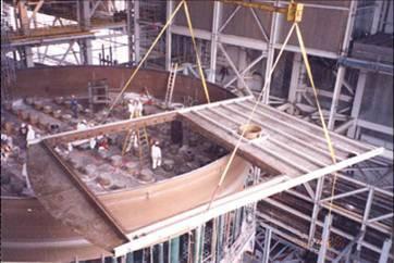
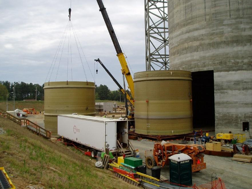
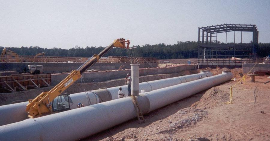


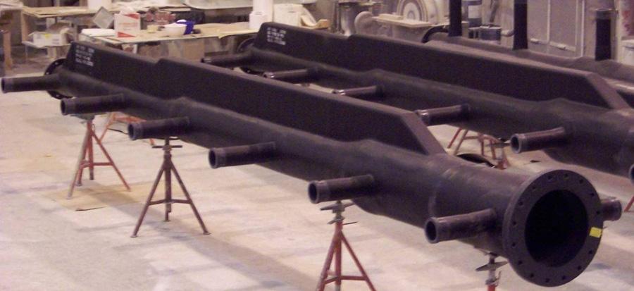


27 Ershigs Stopline-G2 FRP Products for FGD & Utility Applications Stopline-G2 Self-Supporting Spray Headers FRP Chimney Liners Specialty Scrubber Components FRP Ductwork FRP Tanks Circulation Water Piping
FRP PIPE, DUCT AND FITTINGS ENGINEERING GUIDE AND SPECIFICATIONS SIXTH EDITION
 FRP PIPE, DUCT AND FITTINGS ENGINEERING GUIDE AND SPECIFICATIONS SIXTH EDITION Ershigs, Inc. The Leader in FRP Systems Since 92, Ershigs, Inc. has been providing industry with quality metal products and
GREEN THREAD Piping Systems
 Bulletin No. A1300 February 15, 2006 SMITH FIBERCAST GREEN THREAD Piping Systems PRODUCT GREEN THREAD pipe is filament wound using an amine cured epoxy resin and fiberglass and has a resin-rich liner reinforced
CERAM CORE Abrasion Resistant Piping for Power Generation Applications
 Manual No. A1700 July 1, 2005 SMITH FIBERCAST CERAM CORE Abrasion Resistant Piping for Power Generation Applications Long Lasting Abrasion Resistant Lightweight CERAM CORE Pipe Outlasts carbon steel, cast
Centricast CL-1520 Pipe Product Data
 Centricast CL-1520 Pipe Product Data Product Name 14/15 CHEMICAL INDUSTRIAL Applications Acids Salts Oxidizing Agents Chloride Water Materials and Construction All pipe is manufactured with glass fabrics
Ceram Core Product Data
 Ceram Core Product Data Product Name 14/15 CHEMICAL & INDUSTRIAL Applications Bottom Ash Wet Fly Ash Vanadium Ore Slurries Potash Tailings Zinc Tailings Taconite Tailings Heavy Salt Slurries Uranium Ore
Bulletin No. A1380 September 15, Smith Fibercast CENTRICAST PLUS RB-2530 Piping Systems
 Bulletin No. A1380 September 15, 2005 Smith Fibercast CENTRICAST PLUS RB-2530 Piping Systems PRODUCT CENTRICAST PLUS RB-2530 pipe is manufactured with high strength glass fabrics and our highly resilient
ENGINEERING CATALOGUE Version 1.4
 ENGINEERING CATALOGUE Version 1.4 Fiberglass Reinforced Composites Piping Tanks Equipment Engineering Services Table of Contents Commitment...3 Cooling Tower Piping...4 Tank & Vessels...5 FRP Piping &
SAMPLE SPECIFICATIONS FOR PREFABRICATED FRP LIFT STATIONS
 SECTION 1-GENERAL 1 DESCRIPTION a. Scope of Work: i. Contractor shall furnish labor, materials, equipment, and performance of all work necessary or incidental to furnish and install a simplex/duple x-prefabricated
Series 4000 Fiberglass Pipe and Fittings
 FIBERGLASS PIPE GROUP Bondstrand Product Data with guide specification Series 4000 Fiberglass Pipe and Fittings for corrosive industrial service 2-6 installs with no shaving required Uses and applications
Bondstrand Series 3000 Fiberglass Pipe for General Industrial Service
 Bondstrand Series 3000 Fiberglass Pipe for General Industrial Service Uses and Applications Boiler feed water Bridge, roof and floor drains Brine and brackish water Chemical process piping Cooling water
Bondstrand Series 3000A Fiberglass Pipe for General Industrial Service
 Bondstrand Series 3000A Fiberglass Pipe for General Industrial Service Uses and Applications Alcohol solutions Boiler feed water Bridge, roof and floor drains Brine and brackish water Chemical process
SPECIFICATION FIBERGLASS REINFORCED PLASTIC LIQUID CHEMICAL STORAGE TANKS
 FIBERGLASS REINFORCED PLASTIC LIQUID CHEMICAL STORAGE TANKS PART 1. GENERAL 1.1 WORK INCLUDED A. This section covers the work necessary to design, manufacture and supply stationary chemical storage tanks
- TABLE OF CONTENTS -
 - TABLE OF CONTENTS - SINGLE WALL SPECIFICATIONS SECTION 1. APPLICABLE STANDARDS PAGE 1 2. INFORMATION TO BE SUPPLIED BY CUSTOMER PAGE 2 3. MATERIALS PAGE 2 4. LAMINATE CONSTRUCTION PAGE 3 5. LAMINATE
By: Frank Britt PE. Britt Engineering Associates, Inc. Birmingham, ALL Design Guide: Supporting FRP Piping Systems
 L Design Guide: Supporting FRP Piping Systems By: Frank Britt PE This paper presents a method of analysis and illustrations of typical supports that were developed specifically for Fiberglass Reinforced
SPECIFICATION FOR FIBERGLASS REINFORCED PLASTIC CHEMICAL STORAGE TANKS
 The following specification for FRP Chemical Storage Tanks has been developed to assist the specifier and the buyer in detailing their own specification for equipment that meets the minimum design parameters
Resin Systems, Inc. NBS Voluntary Product Standard PS PRODUCT STANDARDS
 Resin Systems, Inc. NBS Voluntary Product Standard PS 15-69 PRODUCT STANDARDS Product Standards are published voluntary standards that establish (1) dimensional requirements for standard sizes and types
- TABLE OF CONTENTS -
 - TABLE OF CONTENTS - DOUBLE WALL SPECIFICATIONS SECTION 1. APPLICABLE STANDARDS PAGE 1 2. INFORMATION TO BE SUPPLIED BY CUSTOMER PAGE 2 3. MATERIALS PAGE 2 4. LAMINATE CONSTRUCTION PAGE 3 5. LAMINATE
Bondstrand Series 3300 Fiberglass Pipe (General Industrial Service) (For sizes 2 through 6 inch, use Series 3000 pipe and fittings products)
 (For sizes 2 through 6 inch, use Series 3000 pipe and fittings products)") Bondstrand Series 3300 Fiberglass Pipe (General Industrial Service) (For sizes 2 through 6 inch, use Series 3000 pipe and fittings products) Uses and Applications Boiler feed water Brine and brackish water
Bondstrand Series 3300 Fiberglass Pipe (General Industrial Service) (For sizes 2 through 6 inch, use Series 3000 pipe and fittings products) Uses and Applications Boiler feed water Brine and brackish water
When a standard or other referenced document referred to in this specification is superseded by an approved revision, the revision shall apply.
 I. References When a standard or other referenced document referred to in this specification is superseded by an approved revision, the revision shall apply. II. Listing The conduit shall be listed by
Bulletin No. A1300 November 1, Smith Fibercast GREEN THREAD Piping Systems
 Bulletin No. A1300 Novemer 1, 2006 Smith Fiercast GREEN THREAD Piping Systems PRODUCT GREEN THREAD pipe is filament wound using an amine-cured epoxy resin and fierglass and has a resinrich liner reinforced
ENGINEERING SPECIFICATION NON-MAGNETIC RAISED FLOOR SYSTEM FOR MRI ROOM APPLICATIONS
 ENGINEERING SPECIFICATION NON-MAGNETIC RAISED FLOOR SYSTEM FOR MRI ROOM APPLICATIONS PULTRUDED DYNAFORM FIBERGLASS STRUCTURAL SHAPES FIBERGRATE COVERED TOP MICRO-MESH MOLDED GRATING WITH NON-MAGNETIC GRATING
ENGINEERING SPECIFICATION PULTRUDED DYNAFORM FIBERGLASS STRUCTURAL SHAPES FIBERGRATE MOLDED GRATING WITH GRATING PEDESTALS. January 24,
 ENGINEERING SPECIFICATION PULTRUDED DYNAFORM FIBERGLASS STRUCTURAL SHAPES FIBERGRATE MOLDED GRATING WITH GRATING PEDESTALS January 24, 2014 06600-1 SECTION 06610 FIBERGLASS REINFORCED PLASTICS (FRP) FABRICATIONS
ENGINEERING SPECIFICATION PULTRUDED DYNADECK INTERLOCKING FLOORING
 ENGINEERING SPECIFICATION PULTRUDED DYNADECK INTERLOCKING FLOORING January 24, 2014 06610-1 SECTION 06610 FIBERGLASS REINFORCED PLASTICS (FRP) FABRICATIONS PULTRUDED FIBERGLASS INTERLOCKING FLOORING PART
Dynaform Fiberglass Structural Shapes. Design Guide. High Performance Composite Solutions. Corrosion Resistant. Fire Retardant.
 Design Guide Dynaform Fiberglass Structural Shapes Corrosion Resistant Fire Retardant Low Maintenance Light Weight Long Service Life High Performance Composite Solutions Pultrusion Process Pultrusion is
SECTION FRP GRATING, HANDRAIL, AND SUPPORTS
 PART 1 GENERAL 1.01 SCOPE OF WORK A. The Contractor shall furnish, fabricate (where necessary), and install all fiberglass reinforced plastic (FRP) items, with all appurtenances, accessories and incidentals
Uses and Applications. Performance
 Bondstrand Series 3200 Fiberglass Pipe Class 200 Fire Protection and General Industrial Service (For 2-6 inch diameters, use Series 3000 pipe and Fittings) Uses and Applications Boiler feed water Brine
WEIR PLATES & SCUM BAFFLES
 WEIR PLATES & SCUM BAFFLES Bedford Reinforced Plastics Weir Plates and Scum Baffles are available in any SIZE, any LENGTH and any CONFIGURATION Benefits Corrosion Resistant Maintenance Free Strong Easy
Perry Fiberglass Products, Inc. LEADERS IN FIBERGLASS REINFORCED PLASTIC DUCT PRODUCTS
 5415 VILLAGE DRIVE ROCKLEDGE, FL 32955 JOINING PROCEDURES FOR WET LAY-UP PAGE 1 JOINING PROCEDURES FOR FIBERGLASS REINFORCED PLASTIC (FRP) RESIN FABRICATORS WET LAY-UP BONDING INSTRUCTIONS Job Preparation:
BONDSTRAND Glassfiber Reinforced Epoxy Piping Systems for Offshore Applications
 BONDSTRAND Glassfiber Reinforced Epoxy Piping Systems for Offshore Applications Bondstrand Glassfiber Reinforced Epoxy Piping Systems Historically, offshore production platform, drilling rig and FPSO owners
FIBERGLASS REINFORCED PLASTIC (FRP) LAUNDER COVERS
 LAUNDER COVERS") FIBERGLASS REINFORCED PLASTIC (FRP) LAUNDER COVERS PART 1 GENERAL 1.1. SUMMARY A. This Section includes fiberglass reinforced plastic (FRP) launder covers for clarifier basins and other applications as
FIBERGLASS REINFORCED PLASTIC (FRP) LAUNDER COVERS PART 1 GENERAL 1.1. SUMMARY A. This Section includes fiberglass reinforced plastic (FRP) launder covers for clarifier basins and other applications as
Powell. Sodium Hypochlorite Fiberglass Reinforced Plastic (FRP) Storage Tanks
 Storage Tanks") Powell Fabrication & Manufacturing Inc Last Updated: April 21, 2000 Sodium Hypochlorite Fiberglass Reinforced Plastic (FRP) Storage Tanks Part 1 General 1.01 Section includes A. Design and furnishing of
Powell Fabrication & Manufacturing Inc Last Updated: April 21, 2000 Sodium Hypochlorite Fiberglass Reinforced Plastic (FRP) Storage Tanks Part 1 General 1.01 Section includes A. Design and furnishing of
ENGINEERING SPECIFICATION PULTRUDED DYNAFORM FIBERGLASS STRUCTURAL SHAPES. March 16,
 ENGINEERING SPECIFICATION PULTRUDED DYNAFORM FIBERGLASS STRUCTURAL SHAPES March 16, 2015 06610-1 SECTION 06610 FIBERGLASS REINFORCED PLASTICS (FRP) FABRICATIONS PULTRUDED FIBERGLASS STRUCTURAL SHAPES PART
Perry Fiberglass Products, Inc. LEADERS IN FIBERGLASS REINFORCED PLASTIC PIPE PRODUCTS
 5415 Village Drive Rockledge, FL 32955 PHONE: 321 609 9036 FAX: 321 609 9003 JOINING PROCEDURES FOR WET LAY-UP PAGE 1 JOINING PROCEDURES FOR FIBERGLASS REINFORCED PLASTIC (FRP) RESIN FABRICATORS WET LAY-UP
Dynaflow Lectures - March 26 th Fiberglass Pipe Systems
 Dynaflow Lectures - March 26 th 2009 Fiberglass Pipe Systems Agenda Standards, very different markets. Why should we choose for Glassfibre Reinforced. materials for piping systems. Product Ranges and Methods
ITEM NO SLIPLINING SANITARY SEWERS
 ITEM NO. 1100 SLIPLINING SANITARY SEWERS 1100.1 DESCRIPTION: Sliplining is accomplished by pulling or pushing liner pipe into existing sewers by use of mechanical or hydraulic equipment. Once in place,
Fiberstrut Parts Catalogue
 Fiberstrut s Catalogue 1 Technical Information Fiberstrut Fabrication The installation of fiberglass channels and accessories is similar to the installation of metallic channels and accessories. All standard
Water & Industrial Products Catalog
 Water & Industrial Products Catalog www.smith-blair.com info@smith-blair.com Phone: 800..9705 or 870.77.527 After Hours Number: 90.277.998 Fax: 800.8.792 or 870.77.52 EMERGENCY PHONE 90.277.998 In the
San Antonio Water System Standard Specifications for Construction ITEM NO. 848 SANITARY SEWERS
 ITEM NO. 848 SANITARY SEWERS 848.1 DESCRIPTION: This item shall govern the furnishing, installation and jointing of sanitary sewer pipe of the size and type specified by the project's plans and specifications.
Time-Tested Fiberglass Piping Systems for Water Applications From Smith Fibercast. Bulletin No. C3320 November 1,2005
 Time-Tested Fiberglass Piping Systems for Water Applications From Smith Fibercast Bulletin No. C3320 November 1,2005 Choosing a Piping System FGS Smith Fibercast offers: Superior Material Performance -
Glass Steel, InC. 1. Fiberglass Composite Troughs. Elmira, CA Flat Bottom Curved Troughs
 Glass Steel, InC. 1 Fiberglass Composite Troughs Elmira, CA Flat Bottom Curved Troughs Glass Steel, InC. 2 Fiberglass composite troughs Glass-Steel, Inc. manufactures a proprietary system of composite
FRP Specifications. Section Fiberglass Reinforced Polymer (FRP) Baffle Wall Panel Products and Fabrications REVISED 11.
 Baffle Wall Panel Products and Fabrications REVISED 11.") FRP Specifications Section 06 70 00 Fiberglass Reinforced Polymer (FRP) Baffle Wall Panel Products and Fabrications REVISED 11.2016 BRISTOL FACILITY 400 Commonwealth Ave., P. O. Box 580, Bristol, VA 24203-0580
FRP Specifications Section 06 70 00 Fiberglass Reinforced Polymer (FRP) Baffle Wall Panel Products and Fabrications REVISED 11.2016 BRISTOL FACILITY 400 Commonwealth Ave., P. O. Box 580, Bristol, VA 24203-0580
SECTION HANGERS AND SUPPORTS FOR PLUMBING
 SECTION 22 05 29 HANGERS AND SUPPORTS FOR PLUMBING PART 1 - GENERAL 1.1 RELATED DOCUMENTS A. Drawings and general provisions of the Contract, including General and Supplementary Conditions and Division
SECTION VIBRATION CONTROLS FOR HVAC PIPING AND EQUIPMENT
 Page 230548-1 SECTION 230548 - PART 1 - GENERAL 1.1 RELATED DOCUMENTS A. Drawings and general provisions of the Contract, including General and Supplementary Conditions and Division 01 Specification Sections,
ENGINEERING SPECIFICATION FIBERTRED MOLDED STAIR TREADS SECTION 06610
 ENGINEERING SPECIFICATION FIBERTRED MOLDED STAIR TREADS SECTION 06610 PART 1 - GENERAL 1.1 SCOPE OF WORK FIBERGLASS REINFORCED PLASTICS (FRP) FABRICATIONS MOLDED STAIR TREADS A. The CONTRACTOR shall furnish,
SECTION HIGH DENSITY POLYETHYLENE PIPE AND FITTINGS (PRESSURE PIPE)
") SECTION 02623 HIGH DENSITY POLYETHYLENE PIPE AND FITTINGS (PRESSURE PIPE) PART 1 - GENERAL 1.1 SCOPE OF WORK A. Furnish all labor, materials, equipment and incidentals required and install high density
SECTION 02623 HIGH DENSITY POLYETHYLENE PIPE AND FITTINGS (PRESSURE PIPE) PART 1 - GENERAL 1.1 SCOPE OF WORK A. Furnish all labor, materials, equipment and incidentals required and install high density
SECTION VIBRATION AND SEISMIC CONTROLS FOR HVAC PIPING AND EQUIPMENT
 SECTION 230548 - VIBRATION AND SEISMIC CONTROLS FOR HVAC PIPING AND EQUIPMENT PART 1 - GENERAL 1.1 RELATED DOCUMENTS A. Drawings and general provisions of the Contract, including General and Supplementary
ENGINEERING SPECIFICATION PULTRUDED DYNARAIL FIBERGLASS GUARDRAIL AND HANDRAIL. January 24,
 ENGINEERING SPECIFICATION PULTRUDED DYNARAIL FIBERGLASS GUARDRAIL AND HANDRAIL January 24, 2014 06610-1 SECTION 06610 FIBERGLASS REINFORCED PLASTICS (FRP) FABRICATIONS PULTRUDED TUBE GUARDRAIL AND HANDRAIL
ENGINEERING SPECIFICATION PULTRUDED DYNARAIL FIBERGLASS GUARDRAIL AND HANDRAIL. January 24,
 ENGINEERING SPECIFICATION PULTRUDED DYNARAIL FIBERGLASS GUARDRAIL AND HANDRAIL January 24, 2014 06610-1 SECTION 06610 FIBERGLASS REINFORCED PLASTICS (FRP) FABRICATIONS PULTRUDED TUBE GUARDRAIL AND HANDRAIL
When a standard or other referenced document referred to in this specification is superseded by an approved revision, the revision shall apply.
 I. References When a standard or other referenced document referred to in this specification is superseded by an approved revision, the revision shall apply. II. Listing The conduit shall be listed by
FRP Specifications. Section Fiberglass Reinforced Polymer (FRP) Hollow Core Building Panels Products and Fabrications REVISED 11.
 Hollow Core Building Panels Products and Fabrications REVISED 11.") FRP Specifications Section 06 70 00 Fiberglass Reinforced Polymer (FRP) Hollow Core Building Panels Products and Fabrications REVISED 11.2016 BRISTOL FACILITY 400 Commonwealth Ave., P. O. Box 580, Bristol,
FRP Specifications Section 06 70 00 Fiberglass Reinforced Polymer (FRP) Hollow Core Building Panels Products and Fabrications REVISED 11.2016 BRISTOL FACILITY 400 Commonwealth Ave., P. O. Box 580, Bristol,
FIBERGLASS ROUND CONTROL DAMPERS. Model K-RD INTRODUCTION M.K. PLASTICS PROVIDES FOUR DAMPER MODELS K-RD SUGGESTED SPECIFICATION
 INTRODUCTION The M.K. Plastics series K-RD are manufactured to meet the needs of the odor control and corrosive HVAC industries by providing a corrosion-resistant FRP Damper that is used to regulate an
ENGINEERING SPECIFICATION FIBERGRATE 62% OPEN AREA/ADA COMPLIANT MOLDED GRATING. January 5,
 ENGINEERING SPECIFICATION FIBERGRATE 62% OPEN AREA/ADA COMPLIANT MOLDED GRATING January 5, 2016 06610-1 SECTION 06610 FIBERGLASS REINFORCED PLASTICS (FRP) FABRICATIONS MOLDED GRATING PART 1 - GENERAL 1.1
ENGINEERING SPECIFICATION. PULTRUDED PEDESTRIAN FIBERGLASS GRATING SAFE-T-SPAN T1210 VINYL ESTER and ISOPHTHALIC. October 25, 2004 Revision 1
 ENGINEERING SPECIFICATION PULTRUDED PEDESTRIAN FIBERGLASS GRATING SAFE-T-SPAN T1210 VINYL ESTER and ISOPHTHALIC 1 PART 1 - GENERAL 1.1 SCOPE OF WORK SECTION 06610 FIBERGLASS REINFORCED PLASTICS (FRP) FABRICATIONS
SECTION STORM DRAINAGE
 SECTION 02720 STORM DRAINAGE PART 1 - GENERAL 1.01 WORK INCLUDED A. Trenching and other excavation. B. Ground water control. C. Pipe bedding. D. Installation of storm drains and appurtenances. E. Installation
ENGINEERING SPECIFICATION FIBERGRATE MOLDED GRATING
 ENGINEERING SPECIFICATION FIBERGRATE MOLDED GRATING 1 PART 1 - GENERAL 1.1 SCOPE OF WORK SECTION 06610 FIBERGLASS REINFORCED PLASTICS (FRP) FABRICATIONS MOLDED GRATING A. The CONTRACTOR shall furnish,
ASME B31.3 Process Piping
 ASME B31.3 Process Piping Charles Becht IV, PhD, PE Don Frikken, PE Instructors BECHT ENGINEERING COMPANY, INC. Nonmetallic Piping - 1 Piping Development Process 1. Establish applicable system standard(s)
Solving Corrosion Problems with VIPEL Composites
 Solving Corrosion Problems with VIPEL Composites Slide 1 Welcome to the seminar on Solving Corrosion Problems with Fiberglass Composites. The Solution is AOC VIPEL, CORROSION RESISTANT RESINS Slide 2 Shows
PRODUCT SPECIFICATIONS PULTRUDED GRATING AND TREADS SECTION PART 1 GENERAL
 PRODUCT SPECIFICATIONS PULTRUDED GRATING AND TREADS SECTION 06600 PART 1 GENERAL 1.1 Related Documents A. Drawings and general provisions of Contract, including General and Supplementary Conditions and
GREEN THREAD Marine-Offshore Piping Systems. Bulletin No. C3800 May 1, 2007
 GREEN THREAD Marine-Offshore Piping Systems Bulletin No. C3800 May 1, 007 Fiber Glass Systems (FGS) combines the resources of Star Fiberglass and Smith Fibercast with five manufacturing facilities in North
Bulletin No. A1200 May 15, Smith Fibercast RED THREAD II Piping Systems
 Bulletin No. A1200 May 15, 2006 Smith Fiercast RED THREAD II Piping Systems PRODUCT Red Thread II pipe is a filament wound product using epoxy resins and continuous glass filaments with a resin rich interior
Product Guide Specification
 MFG Water Treatment Products Company 55 Fourth Avenue PO Box 458 Union City, Pennsylvania 16438 Toll Free (877) 826-2509 Phone (814) 438-3959 Fax (814) 438-8538 Web Site www.mfgwtp.com Product Guide Specification
 Meter Swivels Insulated Unions Meter Sets Meter Accessories The Right Connection 1-800-654-3872 1-405-273-6302 www.centralplastics.com : Overview Georg Fischer Central Plastics entered the meter connection
IntegraLine FRP SOLUTIONS MADE SIMPLER
 Integraine Standard orem Ipsum FRP Pipe Dolor For Sit Chemical Amet Coret Processing Detum Plants FRP SOUTIONS MADE SIMPER Introduction Introducing Integraine* Pipe After years of serving corrosion-related
SPECIFICATIONS - DETAILED PROVISIONS Section Stainless Steel Sluice Gates C O N T E N T S
 SPECIFICATIONS - DETAILED PROVISIONS Section 11294 - Stainless Steel Sluice Gates C O N T E N T S PART 1 - GENERAL... 1 1.01 SUMMARY... 1 1.02 REFERENCES... 1 1.03 DEFINITIONS... 1 1.04 DESIGN REQUIREMENTS...
ENGINEERING SPECIFICATION PULTRUDED FIBERGLASS GRATING SAFE-T-SPAN HIGH LOAD CAPACITY (47% OPEN AREA) VINYL ESTER. January 24,
 VINYL ESTER. January 24,") ENGINEERING SPECIFICATION PULTRUDED FIBERGLASS GRATING SAFE-T-SPAN HIGH LOAD CAPACITY (47% OPEN AREA) VINYL ESTER January 24, 2014 06610-1 SECTION 06610 FIBERGLASS REINFORCED PLASTICS (FRP) FABRICATIONS
ENGINEERING SPECIFICATION PULTRUDED FIBERGLASS GRATING SAFE-T-SPAN HIGH LOAD CAPACITY (47% OPEN AREA) VINYL ESTER January 24, 2014 06610-1 SECTION 06610 FIBERGLASS REINFORCED PLASTICS (FRP) FABRICATIONS
SECTION ALUMINUM GATES
 P.O. Box 1058 370 South Athol Rd. Athol, Massachusetts 01331 Phone: (978) 249-7924 Fax: (978) 249-3072 SECTION ALUMINUM GATES PART 1 GENERAL 1.01 SCOPE OF WORK A. The CONTRACTOR shall furnish all labor,
SECTION HIGH DENSITY POLYETHYLENE PIPE AND FITTINGS
 SECTION 02620 PART 1 GENERAL 1.1 SCOPE OF WORK A. Furnish all labor, materials, equipment, and incidentals required to install High Density Polyethylene (HDPE) pressure pipe, fittings, and appurtenances
Stainless Steel Aeration Equipment Specification
 Section 15 Stainless Steel Aeration Equipment Specification Part 1 - General 1.01 Description A. Scope of Work 1. Furnish, install and test aeration system including air mains, drop pipes, valves, expansion
EVALUATION OF GLASS REINFORCED PLASTIC PIPE COUPLINGS FOR HIGH PRESSURE APPLICATIONS
 EVALUATION OF GLASS REINFORCED PLASTIC PIPE COUPLINGS FOR HIGH PRESSURE APPLICATIONS J GUTMAYER UNIVERSITY OF THE WITWATERSRAND 1 EVALUATION OF GLASS FIBRE REINFORCED PLASTIC PIPE COUPLINGS FOR HIGH PRESSURE
SECTION VIBRATION CONTROLS FOR PLUMBING PIPING AND EQUIPMENT
 Page 220548-1 SECTION 220548 - PART 1 - GENERAL 1.1 RELATED DOCUMENTS A. Drawings and general provisions of the Contract, including General and Supplementary Conditions and Division 01 Specification Sections,
NORTH HARRIS COUNTY REGIONAL WATER AUTHORITY PIPE HANGERS, Section PIPE HANGERS, SUPPORTS, AND RESTRAINTS
 PART 1 GENERAL 1.01 SUMMARY Section 15140 PIPE HANGERS, This Section includes the furnishing and subsequent installation of: A. Pipe and equipment hangers, supports, and associated anchors B. Equipment
Style 204 EPS Product Specification
 Style 204 EPS Product Specification 1.0 Application The Style 204 EPS is used in rigid piping systems to compensate for axial, lateral, torsional and angular movement and misalignment due to thermal expansion
SECTION ALUMINUM HANDRAIL SYSTEMS
 SECTION 05520 ALUMINUM HANDRAIL SYSTEMS PART 1 - GENERAL 1.01 SUMMARY A. Section includes aluminum handrails and railings. B. Related Work: 1. Section 03300 - Cast-in-Place Concrete C. References: 1. American
FYBROC SERIES 2530 CLOSE-COUPLED SEALLESS PUMPS
 FYBROC SERIES 2530 CLOSE-COUPLED SEALLESS PUMPS Capacities to 1500 GPM (350 m 3 /hr) Heads to 00 feet (125 m) Powers to 100 HP (75 kw) Temperatures to 200 F (93 C) Working Pressures to 200 PSI (1,380 kpa)
TAMDID PIPES GRP MANHOLE BROCHURE
 TAMDID PIPES GRP MANHOLE BROCHURE 1) Types & Description of Manholes: Tamdid Pipes offer two types of Manholes; Structural and Liner Manholes: a. Structural Manholes Tamdid Pipes offers concentric and
UNIVERSITY OF MISSOURI Hydronic Energy Distribution 2016 Q1
 GENERAL: The scope of this document is to provide instruction for the installation and testing of chilled water piping installed for the University of Missouri. DESIGN GUIDELINES: 1. Materials 1.1. Pipe
SECTION VIBRATION AND SEISMIC CONTROLS FOR ELECTRICAL SYSTEMS
 PART 1 - GENERAL 1.1 RELATED DOCUMENTS A. Drawings and general provisions of the Contract, including General and Supplementary Conditions, apply to this Section. 1.2 SUMMARY A. This Section includes the
DUCTILE IRON PIPE AND FITTINGS
 Section 02501 PART 1 G E N E R A L 1.01 SECTION INCLUDES A. Ductile iron pipe and fittings for water lines, wastewater force mains, gravity sanitary sewers, and storm sewers. 1.02 MEASUREMENT AND PAYMENT
ENGINEERING SPECIFICATION FIBERGRATE 1 INCH DEEP MICRO-MESH MOLDED GRATING SECTION 06610
 ENGINEERING SPECIFICATION FIBERGRATE 1 INCH DEEP MICRO-MESH MOLDED GRATING SECTION 06610 PART 1 - GENERAL 1.1 SCOPE OF WORK FIBERGLASS REINFORCED PLASTICS (FRP) FABRICATIONS 1 INCH DEEP MICRO-MESH MOLDED
A. This section is intended to provide design guidelines for Utility Direct Buried Piping and Conduit Systems.
 Date Description of Change Pages / Sections Modified ID 6/15/16 Entire document - mgl44 PART 1 - INTRODUCTION 1.1 PURPOSE A. This section is intended to provide design guidelines for Utility Direct Buried
TECHNICAL SPECIFICATION FOR CURED-IN-PLACE MANHOLE REHABILITATION LINER SYSTEM
 TECHNICAL SPECIFICATION FOR CURED-IN-PLACE SYSTEM PART 1 GENERAL 1.01 SCOPE OF WORK Furnish all materials, labor, equipment, tools and required incidentals for providing and installing a resin impregnated
SECTION C1 DUCTILE IRON PIPE AND FITTINGS GENERAL
 SECTION C1 DUCTILE IRON PIPE AND FITTINGS GENERAL This section covers the furnishing and installation of ductile iron water pipe, fittings, thrust restraint and pipe disinfection. Ductile Iron Pipe MATERIALS
San Antonio Water System Standard Specifications for Construction ITEM NO. 813 WATER SERVICE FOR FIRELINES
 ITEM NO. 813 WATER SERVICE FOR FIRELINES 813.1 DESCRIPTION: This item shall consist of water service for fire line installations in accordance with these specifications and as directed by the Engineer.
TAMDID PIPES ABOVE GROUND FIBERGLASS STORAGE TANKS
 TAMDID PIPES ABOVE GROUND FIBERGLASS STORAGE TANKS Tamdid Pipes Fiberglass tanks provide an excellent vessel for drinking water, waste water and fire protection water needs. These tanks are made from Polyester
05510: TAPERED STEEL TROLLEY POLES AND ACCESSORIES
 PART 1 GENERAL 1.01 DESCRIPTION A. The Vendor shall fabricate, furnish, test and deliver tapered steel trolley poles, including base plates, reinforced hand holes, anchor bolts, nuts and washers, and accessories
FRP Specifications. Section Fiberglass Reinforced Polymer (FRP) Structural Shapes/Plate and Fabrications REVISED
 Structural Shapes/Plate and Fabrications REVISED") FRP Specifications Section 06 71 00 Fiberglass Reinforced Polymer (FRP) Structural Shapes/Plate and Fabrications REVISED 11.2016 BRISTOL FACILITY 400 Commonwealth Ave., P. O. Box 580, Bristol, VA 24203-0580
FRP Specifications Section 06 71 00 Fiberglass Reinforced Polymer (FRP) Structural Shapes/Plate and Fabrications REVISED 11.2016 BRISTOL FACILITY 400 Commonwealth Ave., P. O. Box 580, Bristol, VA 24203-0580
STANDARD SPECIFICATIONS RTPV100 PLAS-TANKS INDUSTRIES, INC. 39 STANDEN DRIVE HAMILTON, OH TELEPHONE (513) FACSIMILE (513)
 FACSIMILE (513)") STANDARD SPECIFICATIONS RTPV100 PLAS-TANKS INDUSTRIES, INC. 39 STANDEN DRIVE HAMILTON, OH 45015 TELEPHONE (513) 942-3800 FACSIMILE (513) 942-3993 Filament Wound and Contact Molded Reinforced Thermoset
STANDARD SPECIFICATIONS RTPV100 PLAS-TANKS INDUSTRIES, INC. 39 STANDEN DRIVE HAMILTON, OH 45015 TELEPHONE (513) 942-3800 FACSIMILE (513) 942-3993 Filament Wound and Contact Molded Reinforced Thermoset
C. OSHPD: Office of Statewide Health Planning and Development for the State of California.
 SECTION 21 05 48 VIBRATION AND SEISMIC CONTROLS FOR FIRE-SUPPRESSION PIPING AND EQUIPMENT PART 1 - GENERAL 1.01 INTENT A. It is the intent of this Specification to provide a basis of design for the vibration
PVC PRESSURE FITTINGS
 GUIDE FOR PVC PRESSURE FITTINGS TABLE OF CONTENTS Introduction 3 Standards and Specifications 3 Products 4 Manufacturing Methods 8 Fabricated Fittings 8 Injection-Molded Fittings 9 Machined Couplings 9
SAFE-TANK DOUBLE WALL TANKS HIGH DENSITY CROSSLINKED POLYETHYLENE STORAGE TANKS WITH OXIDATION RESISTANT LINING SYSTEM (NSF/ANSI 61)
") SAFE-TANK DOUBLE WALL TANKS HIGH DENSITY CROSSLINKED POLYETHYLENE STORAGE TANKS WITH OXIDATION RESISTANT LINING SYSTEM (NSF/ANSI 61) PART 1-GENERAL 1.01 Requirements 1. The CONTRACTOR shall provide SAFE-Tank
SAFE-TANK DOUBLE WALL TANKS HIGH DENSITY CROSSLINKED POLYETHYLENE STORAGE TANKS WITH OXIDATION RESISTANT LINING SYSTEM (NSF/ANSI 61) PART 1-GENERAL 1.01 Requirements 1. The CONTRACTOR shall provide SAFE-Tank
San Antonio Water System Standard Specifications for Construction ITEM NO. 812 WATER MAIN INSTALLATION
 ITEM NO. 812 WATER MAIN INSTALLATION 812.1 DESCRIPTION: This item shall consist of water main installation in accordance with these specifications and as directed by the Engineer. 812.2 MATERIALS: The
Bulletin No. A1580 September 15, Fiber Glass Systems CENTRICAST Plus CL-2030 Piping Systems
 Bulletin No. A1580 Septemer 15, 2007 Fier Glass Systems CENTRICAST Plus CL-2030 Piping Systems CENTRICAST PLUS CL-2030 Pipe PRODUCT CENTRICAST PLUS CL-2030 pipe is manufactured with high strength glass
GLASSFIBER REINFORCED PLASTICS (GRP) MOULDED AND PULTRUDED GRATING
 MOULDED AND PULTRUDED GRATING") Page 1 1. GENERAL GLASSFIBER REINFORCED PLASTICS (GRP) MOULDED AND PULTRUDED GRATING 1.1 All Glass Reinforced Plastic (GRP) Moulded and Pultruded Grating shall be designed, supplied and installed by Yeung
Page 1 1. GENERAL GLASSFIBER REINFORCED PLASTICS (GRP) MOULDED AND PULTRUDED GRATING 1.1 All Glass Reinforced Plastic (GRP) Moulded and Pultruded Grating shall be designed, supplied and installed by Yeung
Style 204 MAX Product Specification
 Style 204 MAX Product Specification 1.0 Application The Style 204 MAX is used in rigid piping systems to compensate for axial, lateral, torsional and angular movement and misalignment due to thermal expansion
HIGH DENSITY CROSSLINKED POLYETHYLENE STORAGE TANKS WITH OXIDATION RESISTANT LINING SYSTEM (NSF/ANSI 61)
") PART 1-GENERAL INTEGRALLY MOLDED FLANGED OUTLET (IMFO ) - COMPLETE DRAIN HIGH DENSITY CROSSLINKED POLYETHYLENE STORAGE TANKS WITH OXIDATION RESISTANT LINING SYSTEM (NSF/ANSI 61) 1.01 Requirements 1. The
PART 1-GENERAL INTEGRALLY MOLDED FLANGED OUTLET (IMFO ) - COMPLETE DRAIN HIGH DENSITY CROSSLINKED POLYETHYLENE STORAGE TANKS WITH OXIDATION RESISTANT LINING SYSTEM (NSF/ANSI 61) 1.01 Requirements 1. The
Meter Connection Products: Overview
 : Overview Georg Fischer Central Plastics entered the meter connection business in 1955 with the design and introduction of the insulated meter swivel and insulated union. We understand the critical nature
Fiberglass Ventilation Ducting
 New Generation of Fiberglass (FRP) New and improved fiberglass ducting in 2015. 25% Improvement in K-Factor. The leakage from the joint was reduced by 57% with the redesigned gasket. Fiberglass ducting
Filament Wound Architectural Columns: Blending Tradition with Technology
 Filament Wound Architectural Columns: Blending Tradition with Technology These unique patented filament wound columns help preserve the past with authentic, perfectly detailed structure that is architecturally
SECTION UTILITY POLYETHYLENE CONTAINMENT PIPE SYSTEMS
 SECTION 02670 UTILITY POLYETHYLENE CONTAINMENT PIPE SYSTEMS PART 1 - GENERAL 1.01 WORK INCLUDED A. Trenching and other excavation. B. Ground water control. C. Pipe bedding. D. Installation of containment
SECTION 200 SANITARY SEWER MATERIAL SPECIFICATIONS
 SECTION 200 SANITARY SEWER MATERIAL SPECIFICATIONS 200-1 MATERIAL SPECIFICATION LIST Rev. May 2011 SEWER UTILITY General: 1. All manufacturers products listed are preferred. Others may be submitted to