Technical Manual. Part 3: Block Wall Design & Construction
|
|
|
- Nickolas Ellis
- 6 years ago
- Views:
Transcription


1 Technical Manual Part 3: Block Wall &
2 .1 Overview This section outlines the many factors to be considered when designing autoclaved aerated concrete (AAC) masonry, provides design tables charts to assist the designer. The section is broken into four major areas being; Background, of CSR Hebel AAC Blockwork, Associated CSR Hebel Products, On-site Considerations. Background Applications Information for AAC Masonry Considerations Considerations of CSR Hebel AAC Blockwork Foundations Movement Robustness Compression Bending Bracing Roof Hold Down Section Associated CSR Hebel Products Lintels U Sections Stair Panels On-site Considerations On-site Hling Installation CSR Hebel Technical Manual January 200.1
3 Background.2 Applications Introduction The versatile nature of CSR Hebel enables the products to be successfully used for all types of building construction. CSR Hebel blocks can be used for loadbearing non-loadbearing walls. The light weight easy workability of CSR Hebel blocks results in quicker more economical building. Housing Importance factors in masonry construction are summarised in the following extract from the University of Newcastle Research Report No by Professor A.W. Page. Housing systems vary in different parts of Australia, with the masonry sometimes serving as a loadbearing element (as in cavity construction), or simply as a veneer. Masonry can be of several different types, with the masonry units being solid or hollow, made from fired clay, concrete, calcium silicate, or more recently lightweight autoclaved aerated concrete (AAC). In all cases the masonry behaves as a brittle material with relatively low tensile strength is therefore prone to cracking. Cracking can be avoided or minimised by ensuring that induced tensile stresses are kept as low as possible, that the tensile strength of the masonry is as high as possible. These objectives can be achieved by correct design detailing of the structure, by maximising the bond strength of the masonry by correct mortar selection good workmanship. The recommended sizes for blockwork in typical domestic housing medium density construction are 200mm for external single skin walls, 100mm or 125mm for internal non-load-bearing walls, 150mm for internal load-bearing walls 125mm where items such as shelving are attached or ceiling height is greater than 3000mm. Foundation design should be in accordance with Australian Stard AS 2870 Residential Slabs Footings in. Unless articulated, all walls built in CSR Hebel should be classed as full masonry for the purpose of footing design. The PowerPanel panel has been used as the cladding component of the CSR Hebel Residential Wall System (RWS) which is marketed at the domestic market. PowerPanel panels are fixed to a lightweight structural steel or timber support system via horizontal metal furring channels. The blockwork CSR Hebel RWS provide thermally superior buildings with low long-term running maintenance costs coupled with short-term gains resulting from shorter construction time, minimum waste of materials, minimum site preparation for foundations an enclosed environment for internal fit-out reducing the effect of weather on construction time. Multi-Residential Blocks are ideal for constructing shafts for risers. The fire insulating qualities of the AAC blocks provides shaft walls that easily exceed fire resistance level (FRL) requirements. In addition, the lightweight nature of the AAC material, large face area of each block easy cutting quality provides the advantage of rapid erection, as the blocks can be easily shaped around the many penetrations. Section CSR Hebel Technical Manual January 200.2
4 .3 Information for AAC Masonry Stards Regulations procedures for the verification of members structures consisting of CSR Hebel autoclaved aerated concrete (AAC) block products are presented in the Australian Stard AS3700:2001 Masonry Structures. The procedures cover the topics of: Classification of AAC Masonry Material Properties Robustness Durability Unreinforced Masonry Slenderness Compression Loading Bending Shear Method for Compressive Strength Assessment Bond Wrench Testing Guidelines The design information, including charts tables, presented in the following section is based on the relevant sections of AS3700, where AAC blockwork is specifically included. For reinforced walls, a structural engineer shall determine the amount of reinforcement to be installed reinforcement spacing. The AAC masonry constructed from CSR Hebel block products is called Plain Masonry the blocks are masonry units referred to as Solid Unit. The type of solid unit is Autoclaved aerated concrete masonry unit complying with AS/NZS 4455 Masonry Units Segment Pavers. For determining the structural resistance of masonry, the following document is CSR Hebel Technical Manual January 200 adopted by reference in the Building Code of Australia: AS Masonry Structures; by association AS/NZS4455 Masonry Units Segmental Pavers Guarantee Certification CSR Hebel is a business of CSR Building Products Limited ABN It is a manufacturer supplier of CSR Hebel Autoclaved Aerated Concrete (AAC) products. Because it is a manufacturer supplier only, CSR Hebel does not employ people qualified as Accredited or Principal Certifiers. CSR Hebel is therefore unable to provide Compliance Certificates or Statements of Compliance. CSR Hebel does guarantee the products manufactured by itself the products used in the systems described in CSR Hebel s literature, subject to the terms conditions of the CSR Hebel Guarantee. CSR Hebel does not however guarantee the components, products or services, such as installation specialist advice, supplied by others. CSR Hebel conducts appropriate testing of its products systems, sources opinions to determine performance levels. These include structural, fire acoustic. Testing opinions are conducted certified by appropriate specialists in these fields. CSR Hebel can provide copies of test results opinions presenting the performance characteristics of its products systems. When using CSR Hebel products systems in specific projects, such specialists should be consulted to ensure compliance with the Building Code of Australia relevant Australian Stards. CSR Hebel can provide a certification for its panel products. For a specific project, an appropriate specialist can provide the certification of the relevant performance criteria of the systems supporting structure..3 Section
5 Cracking in Masonry As a result of the low tensile strength negligible ductility, all forms of masonry construction behave as a brittle material are therefore prone to cracking. Similar to other forms of masonry, careful consideration at design stage attention to detail during construction of autoclaved aerated concrete (AAC) masonry can minimise such adverse effects. It is important to note that the Building Code of Australia is performance based. The performance based approach acknowledges the possibility of cracking does not consider it a defect so long as the structural resistance other design requirements are maintained. Cracking of masonry building elements is often of little consequence, structurally or aesthetically, depending on the wall finishes. The Office of Fair Trading, Guide to Stards Tolerances (April 1999) identifies cracking of more than 1mm a defect in rendered surfaces. This limit is also specified in AS3700 AS2870. Cracks up to 1mm, whilst not considered a defect in these documents, may allow water ingress in single skin masonry construction therefore could be considered a defect under the BCA. This highlights the importance of good coating systems for CSR Hebel blockwork. Coating systems should be able to bridge minor cracking. Cracking can be due to external effects: Foundation support movement. Deformation (shortening, shrinkage, creep, bridging control joints in structure, etc.) in adjacent materials. Workmanship. The material properties of masonry units their mortars must be taken into consideration when designing specifying masonry blockwork to prevent or minimise cracking. AAC differs slightly from clay brick concrete block masonry so in addition to the general behaviour of masonry, the effect of the following differences must be considered: Lower compression capacity. Lower tensile strength. Lower modulus of rupture. Lower coefficients of thermal expansion contraction drying shrinkage. Larger unit size. Laid in thin bed mortar which typically has higher compression capacity than the units. Units are autoclaved. Dissipates absorbs moisture from the atmosphere with associated volume change. Considerations for design detailing: Elements of masonry blockwork must be isolated from movement. Control joints. Wall restraints. The compressive strength of render coatings must not exceed that of the blockwork. Use plasterboard linings internally. Use flexible coating systems that are able to bridge hairline cracks. Apply mesh within the render over areas of high stress. Section CSR Hebel Technical Manual January 200.4
6 .4 Considerations The following are common issues requiring consideration resolution in the application of AAC masonry to individual projects: Approach CSR Hebel suggests considering a wall as having top bottom lateral restraints only (one-way vertical span) designing the appropriate wall thickness, so that retrofitting or changing the location of the movement joints will not be detrimental to the lateral load capacity of the wall. In determining the appropriate wall thickness, the designer shall consider a range of factors relating to relevant codes project specific considerations, these factors may include: Movement joint location. Bracing considerations. Vertical (compression) loading. Out-of-plane wind/earthquake (lateral) loading. Fire Resistance Level (FRL) rating. Dimensional Layout To exploit the modular nature of masonry the tight tolerances of CSR Hebel block products, it is recommended that the designer set out openings to suit a grid which is a multiple of the block length /or height. This will reduce on-site cutting speed up the construction process. Vertical Dimensional Control The preferred multi-modules are 300, mm sub-modules 25, 50 75mm. The CSR Hebel block sizes are consistent with these dimensions. Geometric design of buildings structures takes place in three dimensions, on a horizontal in a vertical plane. The designer as initiator needs to exercise dimensional control by specifying preferred dimensions as far as possible. The following guide is provided to encourage a unified approach to design. It should not however restrict the use of creative or innovative design. Vertical Dimension Control Ceiling Heights Door & Window Head Heights Sill Heights Door Openings Horizontal Dimensional Control Clear space between columns for infill walls Centre to centre spacing of interior columns 1200 Window Openings Ready Reckoner Non-Structural Walls Typically, non-structural internal walls are 100mm thick. It is recommended that the walls be lined both sides with plasterboard sheeting. Structural Walls Generally, the minimum recommended wall thickness, is: 200mm for external walls, (other thicknesses are available: 225, 250 & 300mm) 150mm for internal walls. The particular project loading configurations could result in walls that exceed the above minimum requirements. Section CSR Hebel Technical Manual January 200.5
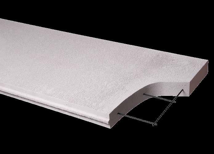
7 Foundations ed for FULL MASONRY or ARTICULATED FULL MASONRY in accordance with Australian Stard AS2870. Movement Joints Movement joints (M.J.) are required to minimise control cracking in a block wall by breaking the wall into separate masonry panels with points of weakness {articulation joints (A.J.) control joints (C.J.)}, which locate allow movement. Refer to Section.7. Joints should be included in all walls, both internal external. Free Sting Walls CSR Hebel walls with returns should be checked for lateral stability. As a rough guide, if a return on a wall is less than 400mm then that end of the wall is without adequate lateral support requires fixing to a support or bracing. In some buildings where window openings go all the way to ceiling height the intermediate wall may be free sting. These blades should be carefully checked braced during construction. Concentrated Loads For large concentrated loads, such as steel beams or girder trusses, supported on CSR Hebel walls these are to be approved by the project engineer. Unsupported Walls Lengths For short lengths of unsupported walls, such as between window openings, without perpendicular cross walls should be avoided. Where possible, such walls should be a minimum of 900mm wide should be approved by the project engineer for structural adequacy. CSR Hebel Technical Manual January 200 Bearing Length Columns For monolithic loads, such as suspended floor slabs roof framing, ensure an adequate bearing width, project engineer to consider the effects of eccentric loading. Likewise, monolithic CSR Hebel AAC columns can be used, but should be designed in accordance with AS Intermediate columns in double garages should be a minimum of 400mm x 300mm to provide adequate seating for lintel beams. It is also recommended that they be constructed using 100mm thick blocks filled with 200mm x 100mm reinforced concrete to the footing roof system..5 Considerations The following are common issues requiring consideration resolution in the application of AAC masonry to individual projects: Coatings & Linings Only coating manufacturer recommended coating systems should be used on CSR Hebel AAC block walls. Ensure coatings are suitable for use on CSR Hebel AAC. Refer to the CSR Hebel Technical Manual Section 9 for further information. CSR Hebel recommends lining 100mm 125mm thick internal block walls with plasterboard sheeting. Bond Breaker Layer A necessary part of a CSR Hebel AAC block wall is the bond breaker layer, which is installed at the base of the wall between the concrete foundation the wall. This layer accommodates the different shrinkage rates differential movement/. Section
8 displacement of the CSR Hebel AAC blockwork concrete by allowing localised slip to occur, which helps relieve any build up of stress. Typically, a dampproof course (DPC) material is used with CSR Hebel AAC block walls to provide a slip plane, as well as prevent rising damp. Walls supporting suspended concrete floors require a suitable slip joint at the interface, such as two layers of greased, galvanised iron sheet. Refer to Section.18 for further details. Damp Proof Course A damp-proof course (DPC) membrane is recommended for use with CSR Hebel walls, to prevent damp rising in masonry. Workmanship Ensure that all perpends are completely filled. Ensure all bed joints perpend joints are approximately 2-3mm thick. Refer to the Installation Section.17, for further details. Timber or Steel Floor Roof Systems Flooring If timber floor joists, timber or particle board flooring is used in conjunction with CSR Hebel products, a minimum 10mm gap must be left at either end where the joists intersect with CSR Hebel products to allow for potential timber movement. Timber bearers joists must sit on a timber plate. Roofing Timber roof design must comply with the forces for the intended design wind loading category. Non conforming roof designs should be checked by a practising structural engineer to ensure that excessive lateral forces are not transmitted into the rigid supporting block walls. The use of bond beams should be included when cathedral type ceilings are used or when roof spreading may be a problem. Movement Joints (M.J.) Attention should be given to ensuring that these joints are kept free of all debris mortar, connectors installed in accordance with manufacturer s recommendations. Importantly, in no circumstances should a movement joint be rendered across. Ensure specified backing rod sealant are installed in accordance with manufacturer s recommendations. Hebel Adhesive The Hebel Adhesive should be prepared in accordance with the instructions on the packaging. Importantly, the adhesive should not be retempered as this will have a detrimental affect on the bond strength. Hebel Highbuild Chasing The Hebel Highbuild render should be prepared in accordance with the instructions on the packaging. Importantly, the render should not be retempered as this will reduce the strength affect the qualities of the render. Refer to Section 5 of Fire in this technical manual. Steel Beams When steel beams are used in conjunction with CSR Hebel AAC construction, the end bearing should be carefully checked. The principles of AS3700 can be adopted for the bearing under a point load, however as a guide for design, a figure of 0.5MPa is conservative for local crushing under the beam. If high loads are involved, bearing plates steel SHS sections can be used. These should be designed by a practicing structural engineer. Section CSR Hebel Technical Manual January 200.7
9 for CSR Hebel Blockwork. Foundations The selection of the foundation type for use with CSR Hebel blockwork is based on AS2870, Residential Slabs Footings. This stard covers the selection of footing designs for the usual range of site conditions, i.e. soil types slopes. Where unusual site or load conditions are encountered, advice should be obtained from a practicing Structural Engineer. It is recommended that a practicing structural engineer is consulted concerning the application of AS 2870 to any particular building construction or site. The approach to foundation design using AS2870 is to first classify the foundation soil, then assess the topography select the appropriate footing design to be used. Following is a guide to this foundation design approach. The structural engineer should approve this approach before adopting. Step One: Classify the Foundation Soil The foundation soil provides support for the building. If there is reactive or expansive clay in the soil, it may swell on wetting shrink on drying, causing foundation movement to an extent that may cause cracking of the walls. The appropriate soil classification for a particular site may be obtained from the following sources: a) Advice from a Geotechnical Engineer. b) Local Council or other local authority for their information on the locality. c) A local Builder or Engineer familiar with the site classification. d) Site testing in accordance with relevant stards. Step Two: Assess the Topography Typical topographical items which should be considered in a site inspection are: a) Is the site level or sloping? If any part of the foundation is on fill more than 50 mm deep the site is classified as sloping. b) What will be the maximum depth of cut? A retaining wall will be required for cuts deeper than 00mm within 2m of the building. c) Can surface water be diverted away from the building? Surface gutters /or agricultural pipes may be required. d) Will it be necessary to fill any part of the site to provide support for the foundations? Fill must be suitably compacted in layers. Fill containing clay will cause many problems. It is preferable to import sy or granular fill. e) Will fill require retaining? Soil filling can be compacted to a slope not steeper than 1:2 without the need for a retaining wall. Note that for sloping sites it may be necessary to retain fill under the slab by using deep edge beams. Step Three: AS2870 Site Classifications Class A Most rock or s sites, with little or no ground movement from soil moisture changes. Class S Class M Slightly reactive clay sites with only slight ground movement. Moderately expansive soils such as certain types of clays or silts. Section CSR Hebel Technical Manual January 200.8
10 Classes H E Highly reactive clays that exhibit substantial extreme movement due to moisture changes. Class P Problem sites such as soft clays silts, loose ss, filled sites, lslips. Reactive sites subject to abnormal moisture conditions. Where detailed knowledge of the underlying soil profile is not known, classification of the site can be determined by appropriate testing using soil shrinkage indices appropriate to the soil profile of the site suction change profiles, which represent the design moisture content to determine the characteristic surface movement, ys. Surface Movement Soil Classification 0 mm < ys < 20 mm S 20mm < ys < 40 mm M 40mm < ys < 70 mm H ys > 70 mm E Step Four: Select the Footing Type Stard designs for footing systems should be selected using Section 3 of AS2870. It is recommended that all walls constructed using CSR Hebel blocks are classified as full masonry. However, unlike clay brick walls, the integrity of a CSR Hebel wall is more critical because of the flush type finish of the coatings used. This requires a stiff footing system when used as either a masonry veneer or a single skin. Unless articulated, all walls built in CSR Hebel should be classified as full masonry for the purpose of footing selection. The wall classification may be changed to articulated full masonry where movement joints are incorporated in the external internal walls at no more than m spacing. Example 1 For a single skin full masonry (nonarticulated) CSR Hebel building on Class M soil, using a stiffened raft on a level site, from Figure 3.1: Refer to Table in Figure 3.1 of AS2870. Depth of edge internal beams: 800mm Maximum spacing of internal beams: 4m Reinforcing in beam: Slab fabric: Example 2 SL92 3 N1 For a single skin articulated CSR Hebel building on Class M soil, using a stiffened raft on a level site: Refer to Table in Figure 3.1 of AS2870. Depth of edge internal beams: 500mm Maximum spacing of internal beams: 4m Reinforcing in beam: Slab fabric: 3 L12TM SL82 SL92 It is recommended that a practicing Structural Engineer is consulted concerning the application of AS2870 to any particular building construction or site. Section CSR Hebel Technical Manual January 200.9
11 .7 Movement Joints (M.J.) During the life cycle of a building, the building the materials that it is constructed from will move. These movements are due to many factors working together or individually, such as foundation movement (shrinkage swelling), thermal expansion contraction, differential movements between materials, climate soil condition. This movement, unless relieved or accommodated for, will induce stress in the materials, which may be relieved in the form of cracking. To accommodate these movements relieve any induced stresses, which could potentially crack the wall, movement joints (vertical gaps) shall be installed. There are two categories of joints: Articulation joints (A.J.) are provided to relieve induced stresses due to foundation movement. The joints make the walls more flexible by breaking the wall into a series of small panels, which is especially required on reactive ground conditions (clay, peat). Differential movement between the AAC blockwork adjacent structural elements need to be accommodated with articulation joints, such as blockwork infill between the structural frame. Control joints (C.J.), (one type is an expansion joint), are provided to relieve the induced stresses resulting from thermal expansion or contraction of the AAC, or differential movement between the AAC another material or structure, such as abutting walls or columns of concrete or brickwork. Control joints can delineate coating shrinkage breaks. A joint may perform the function of either an articulation joint, or control joint, or both. IMPORTANT: There are restrictions provided to the maximum length of wall: metres maximum for continuous runs of walls. CSR Hebel Technical Manual January 200 When measuring the metre run of wall, the measurement continues around corners till the end of the wall or a movement joint. Additionally, the BCA presents the following requirements for articulation joints in unreinforced masonry walls, which is applicable for AAC masonry construction: b) Articulation joints must have a width not less than 10mm be provided: i. in straight, continuous walls having no openings, at not more than m centres not closer than the height of the wall away from corners; ii. where the height of the wall changes by more than 20% at the position of change in height; iii. where openings more than 900x900mm occur, at more than 5m centres, positioned in line with one edge of the opening; iv. where walls change in thickness; v. at control or construction joints in the footing slabs; vi. at junctions of walls constructed of different masonry materials; vii. at deep chases (rebates) for service pipes. CSR Hebel recommends that movement joints be provided in AAC masonry construction for all site soil classifications. For further information refer to the Cement Concrete Aggregates Australia, Technical Note - Joints in Concrete Buildings through website: The project architect engineer shall be responsible for determining the optimum location of movement joints, as their location is dependent on a variety of factors including most importantly the structural stability bracing requirements of the building (see Table.1)..10 Section
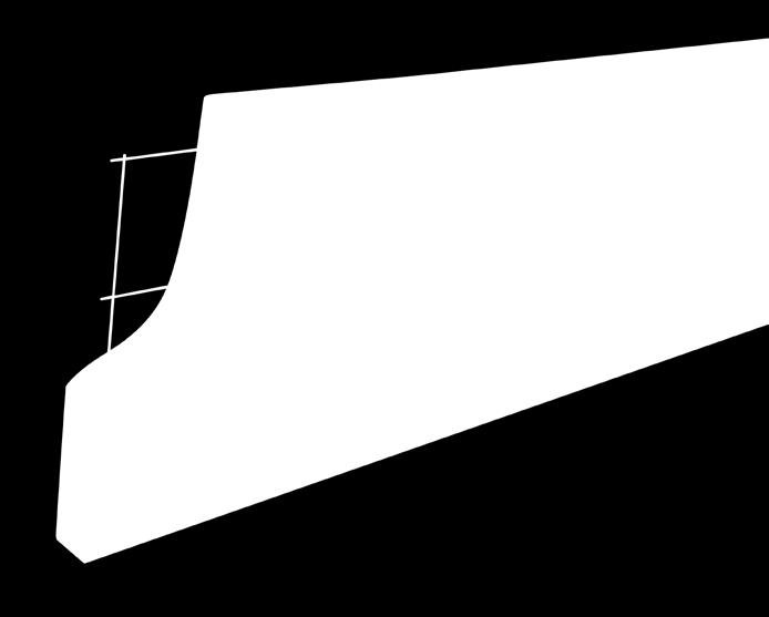
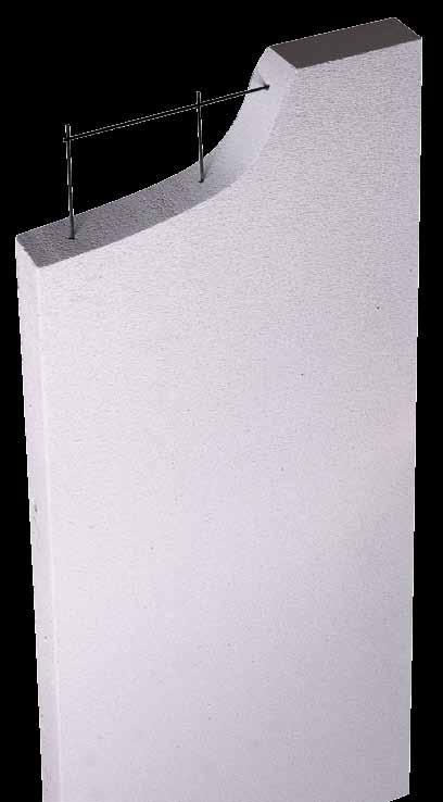
12 Table.1: Maximum Joint Spacings in Block Walls Wall/Footing Articulated Non-Articulated Joint Spacing Specified by Structural Engineer m max. Areas to be considered, but not limited to, include: Long or short walls tied to each end with substantial, rigid return walls. Unless otherwise designed by a structural engineer, movement joints require shear connectors placed across the joints to maintain stability of the walls under lateral loads. Maximum vertical spacing of connectors is 00mm. Approval of the connector spacing shall be provided by the appropriate structural engineer. Refer to Section.18 for Details Section 8 for Fixing Capacities of this manual; Section 3 of the NZ Addendum. Attention should be given to ensuring that these joints are kept free of all debris mortar, connectors installed in accordance with manufacturer s recommendations. Importantly, in no circumstances should a movement joint be rendered across. Section CSR Hebel Technical Manual January
13 .8 Robustness Limits AS 3700 (Clause 4.) requires that members must be designed for robustness. This provides practical limits to slenderness for walls piers must be applied in addition to all other design requirements. Checking robustness is not a substitute for proper engineering design. Each of the various loading conditions (compression, flexure, fire, shear etc.) must be checked designed for as appropriate. The robustness limits are expressed in AS3700 as limiting values of coefficients Cv Ch, as shown in Table.2 for unreinforced walls piers. Table.2: Robustness Coefficients (from AS3700: Table 4.2) Conditions at the Top & Bottom Cv Free top Load other than a concrete slab 27 Loaded by a concrete slab 3 Isolated pier 13.5 Conditions on the Vertical Sides Ch One edge supported 12 Both edges supported 3 The coefficients shown in Table.2 the expressions for slenderness ratio in AS 3700 Section 4..2 have been used to calculate charts for various support loading conditions. These charts are intended for single leaf walls only. Rotational restraint applied to an edge of a wall gives no enhancement to robustness all edge supports are therefore assumed to be simple supports. Each chart is labelled for the relevant loading type shows an icon to indicate the lateral support conditions. Separate lines are shown on each chart for a range of block thickness from 75 mm to 300 mm, where applicable. CSR Hebel Technical Manual January 200 The length height of the wall are clear dimensions between supports or edges in all cases. Where a wall has a door or window opening, the edge of the opening must be considered as a free edge to the wall for its full height, unless a stiffening mullion is specifically designed to support the edge. The robustness of the wall is therefore checked using the length of wall between the lateral support or free edge the edge of the opening, using the appropriate chart for a wall with one or both vertical edges free. The same applies to a control joint, which is always treated as a free edge to the wall it should also be applied in a case where a substantial vertical chase is made in the wall. Control joints should be placed in walls at appropriate spacings as set out in Section.7. Chart RB1 Chart RB2 apply to walls with four sides supported. Chart RB3, Chart RB4 Chart RB7 apply to walls with three edges supported, having either the top or a vertical side free. Chart RB5, Chart RB Chart RB8 apply to walls with two edges supported (either the top bottom or the bottom one side only). In the case of Chart RB5 Chart RB the transitions to the robustness limits for isolated piers are shown. AS3700 Clause requires that a wall must be considered as an isolated pier when the height-to-width ratio is greater than or equal to five..12 Section
14 BlockWall BlockWall Section CSR Hebel Technical Manual January
15 BlockWall BlockWall Section CSR Hebel Technical Manual January
16 BlockWall BlockWall Section CSR Hebel Technical Manual January
17 BlockWall BlockWall Section CSR Hebel Technical Manual January 200.1
18 .9 for Compression The capacity of a member under compression loading depends upon the cross-sectional properties, compressive strength of the material, slenderness of the member the eccentricity of loading at the ends. End eccentricity is determined primarily by the type of loading (roof, floor etc.) the relative magnitude of any bending moments imposed at the ends in conjunction with the vertical loading. AS3700 considers that there is no mutual support between the leaves of a cavity wall under compression loading consequently these charts apply equally to single leaf walls the separate leaves of cavity walls. No distinction is made between simple supports those where there is continuity or another possible source of rotational restraint. Walls can be designed for compression using the rules in AS3700 Clause 7.3, which provides two separate approaches: design by simple rules; design by refined calculation. The former is sufficient for most cases has been used as the basis for design in this manual. Two loading cases are considered here: 1. Loading by a concrete slab supported on the wall. This is treated according to the AS3700 rules for slab loading. 2. Loading by CSR Hebel floor panels supported on the wall. This case is treated according to the AS3700 rules for loading other than a concrete slab. This loading condition would also apply for roof loads supported on the wall. AS3700 caters for various support conditions by the use of slenderness coefficients a v a h as shown in Table.3. Table.3: Slenderness Coefficients (from AS3700 Clause ) Support Conditions at the Top Bottom Lateral support on top bottom 1 Lateral support at bottom only 2.5 Support Conditions at the Sides Lateral support on both vertical edges 1 Lateral support on one vertical edge 2.5 The coefficients shown in Table.3 the expressions for slenderness ratio in AS3700 Clause have been used to generate design charts for various loading support conditions. A capacity reduction factor of 0.45 (AS3700 Table 4.1) the material properties shown in Section 2 have been used. Sets of charts are given for both the CSR Hebel Thermoblok Sonoblok products. Each chart is labelled for the AAC type, wall height relevant loading case, shows an icon to indicate the lateral support conditions. Separate lines are shown on the charts for block thicknesses from 125mm to 300mm. The length height of the wall are clear dimensions between supports or free edges in all cases. Where a wall has a door or window opening, the edge of the opening must be considered as a free edge to the wall for its full height, unless a stiffening mullion is specifically designed to support the edge. The compressive load capacity of the wall is therefore checked for the length of wall between the lateral support the edge of the opening, using the appropriate chart for a wall with one or both vertical edges free. For design purposes, a control joint or substantial vertical chase should also be considered a free edge. Control joints should be designated by the structural engineer. Section.7 presents guidelines on appropriate control joint spacings. a v a h Section CSR Hebel Technical Manual January
19 To use the charts, the factored compression load should be determined in accordance with the relevant Australian stard compared with the load capacity given by the relevant chart for the block type, height, loading/support configuration block thickness. Either the load capacity can be used to derive a limiting length or the length can be used to derive a load capacity. The appropriate chart for any particular set of conditions can be found from Table.4. The charts provide for the design of walls with heights up to 3m. Table.4 Key to Charts Wall Height (m) Four Edges Laterally Supported CSR Hebel Floor Panel Over. Thermoblok One Vertical Edge Free Four Edges Laterally Supported Sonoblok One Vertical Edge Free 2.4 Chart CP1 Chart CP2 Chart CP3 Chart CP4 2.7 Chart CP5 Chart CP Chart CP7 Chart CP8 3.0 Chart CP9 Chart CP10 Chart CP11 Chart CP12 Concrete Slab Over. Thermoblok Sonoblok Wall Height (m) Four Edges Laterally Supported One Vertical Edge Free Four Edges Laterally Supported One Vertical Edge Free 2.4 Chart CP13 Chart CP14 Chart CP15 Chart CP1 2.7 Chart CP17 Chart CP18 Chart CP19 Chart CP Chart CP21 Chart CP22 Chart CP23 Chart CP24 Section CSR Hebel Technical Manual January

20 Chart CP1 : Thermoblok Walls Up To 2.4m High with Four Edges Laterally Supported Loaded by a Hebel Floor Chart CP2: Thermoblok Walls Up To 2.4m High with One Side Free Loaded by a Hebel Floor Section CSR Hebel Technical Manual January
21 Chart CP3: Sonoblok Walls Up To 2.4m High with Four Edges Laterally Supported Loaded by a Hebel Floor Chart CP4: Sonoblok Walls Up To 2.4m High with One Side Free Loaded by a Hebel Floor Section CSR Hebel Technical Manual January
22 Chart CP5: Thermoblok Walls Up To 2.7m High with Four Edges Laterally Supported Loaded by a Hebel Floor Chart CP: Thermoblok Walls Up To 2.7m High with One Side Free Loaded by a Hebel Floor Section CSR Hebel Technical Manual January
23 Chart CP7: Sonoblok Walls Up To 2.7m High with Four Edges Laterally Supported Loaded by a Hebel Floor Chart CP8: Sonoblok Walls Up To 2.7m High with One Side Free Loaded by a Hebel Floor Section CSR Hebel Technical Manual January
24 Chart CP9: Thermoblok Walls Up To 3.0m High with Four Edges Laterally Supported Loaded by a Hebel Floor Chart CP10: Thermoblok Walls Up To 3.0m High with One Side Free Loaded by a Hebel Floor Section CSR Hebel Technical Manual January
25 Chart CP11: Sonoblok Walls Up To 3.0m High with Four Edges Laterally Supported Loaded by a Hebel Floor Chart CP12: Sonoblok Walls Up To 3.0m High with One Side Free Loaded by a Hebel Floor Section CSR Hebel Technical Manual January
26 Chart CP13: Thermoblok Walls Up To 2.4m High with Four Edges Laterally Supported Loaded by a Concrete Slab Chart CP14: Thermoblok Walls Up To 2.4m High with One Side Free Loaded By a Concrete Slab Section CSR Hebel Technical Manual January
27 Chart CP15: Sonoblok Walls Up To 2.4m High with Four Edges Laterally Supported Loaded by a Concrete Slab Chart CP1: Sonoblok Walls Up To 2.4m High with One Side Free Loaded by a Concrete Slab Section CSR Hebel Technical Manual January 200.2
28 Chart CP17: Thermoblok Walls Up To 2.7m High with Four Edges Laterally Supported Loaded by a Concrete Slab Chart CP18: Sonoblok Walls Up To 2.7m High with One Side Free Loaded by a Concrete Slab Section CSR Hebel Technical Manual January
29 Chart CP19: Sonoblok Walls Up To 2.7m High with Four Edges Laterally Supported Loaded by a Concrete Slab Chart CP20: Sonoblok Walls Up To 2.7m High with One Side Free Loaded By a Concrete Slab Section CSR Hebel Technical Manual January
30 Chart CP21: Thermoblok Walls Up To 3.0m High with Four Edges Laterally Supported Loaded by a Concrete Slab Chart CP22: Thermoblok Walls Up To 3.0m High with One Side Free Loaded by a Concrete Slab Section CSR Hebel Technical Manual January
31 Chart CP23: Sonoblok Walls Up To 3.0m High with Four Edges Laterally Supported Loaded by a Concrete Slab Chart CP24: Sonoblok Walls Up To 3.0m High with One Side Free Loaded by a Concrete Slab Section CSR Hebel Technical Manual January
32 .10 for Bending The load capacity of a wall in bending depends upon the cross-sectional properties, characteristic flexural tensile strength, characteristic lateral modulus of rupture of the material, the support conditions at the edges of the wall. Edges can either be free, simply supported, or rotationally restrained. In practice, it is difficult to achieve rotational restraint at the top or bottom edge of a wall. While AS3700 provides for rotational restraint at the vertical edges, this has not been considered in the design charts presented here. AAC walls can be designed for bending using the rules in AS3700 Clause 7.4, where vertical bending is covered by Clause 7.4.2, horizontal bending by Clause two-way bending by Clause Both Clause Clause provide rules specifically for AAC masonry with thinbed joints because its behaviour differs from that of masonry laid in conventional mortar joints. The vertical bending expressions in Clause have been used to derive Chart BD1, using a characteristic flexural tensile strength (f mt ) of 0.2 MPa the factor k mt equal to 1.3 as specified in AS3700 for AAC masonry. Vertical loading enhances the vertical bending strength the selfweight of Thermoblok has been considered for this purpose in the derivation of the chart. Negligible further enhancement would result from the use of Sonoblok the same chart therefore applies to both masonry unit types. The horizontal bending expression in Clause (b) has been used to derive Chart BD2 for Thermoblok walls Chart BD3 for Sonoblok walls of various thicknesses. Characteristic lateral modulus of rupture values appropriate to the two masonry unit types have been used (see Table 2.3 of this publication). CSR Hebel Technical Manual January 200 For walls in two-way bending, AS3700 caters for various support conditions by the use of coefficients b v b h as shown in Table.5. These coefficients the expressions for bending in AS3700 Clause have been used to generate design charts for Thermoblok Sonoblok walls with heights of 2.4, metres (see Chart BD4 to Chart BD15). Each chart shows an icon to indicate the lateral support conditions. Separate lines are shown on the charts for block thicknesses from 75mm to 300mm. AS3700 limits the application of these rules for two-way bending to walls without openings with L/H not exceeding 2.5 (see Clause ). The curves in Chart BD4 to Chart BD15 therefore terminate at the length corresponding to this limit. Table.5: Bending Coefficients (from AS 3700 Table 7.5) Support Conditions at the Top Bottom Lateral support on top bottom 1.0 Lateral support at bottom only 0.25 Support Conditions at the Sides Lateral support on both vertical edges 1.0 A capacity reduction factor of 0. has been used for all bending charts (see AS3700 Table 4.1). The length height of the wall are clear dimensions between supports in all cases. To use the charts, the factored out-ofplane load should be determined in accordance with the relevant Australian stard compared with the load capacity given by the appropriate chart for the block type, wall height, support configuration block thickness. If additional moment capacity is required, the following options can be investigated should be designed by a practicing structural engineer. 1. Precompression via the holding down bolts; or 2. Grouting in of the bolts. b v b h.31 Section
33 Chart BD1: Vertical Bending for Thermoblok Sonoblok Walls Chart BD2: Horizontal Bending for Thermoblok Walls Section CSR Hebel Technical Manual January
34 Chart BD3: Horizontal Bending for Sonoblok Walls Section CSR Hebel Technical Manual January

35 Chart BD4: Two-way Bending for Thermoblok Walls 2.4 m High with Four Edges Laterally Supported Chart BD5: Two-way Bending for Sonoblok Walls 2.4 m High with Four Edges Laterally Supported Section CSR Hebel Technical Manual January

36 Chart BD: Two-way Bending for Thermoblok Walls 2.7 m High with Four Edges Laterally Supported Chart BD7: Two-way Bending for Sonoblok Walls 2.7 m High with Four Edges Laterally Supported Section CSR Hebel Technical Manual January
37 Chart BD8: Two-way Bending for Thermoblok Walls 3.0 m High with Four Edges Laterally Supported Chart BD9: Two-way Bending for Sonoblok Walls 3.0 m High with Four Edges Laterally Supported Section CSR Hebel Technical Manual January 200.3

38 Chart BD10: Two-way Bending for Thermoblok Walls 2.4m High with the Top Free Chart BD11: Two-way Bending for Sonoblok Walls 2.4 m High with the Top Free Section CSR Hebel Technical Manual January

39 Chart BD12: Two-way Bending for Thermoblok Walls 2.7 m High with the Top Free Chart BD13: Two-way Bending for Sonoblok Walls 2.7 m High with the Top Free Section CSR Hebel Technical Manual January

40 Chart BD14: Two-way Bending for Thermoblok Walls 3.0 m High with the Top Free Chart BD15: Two-way Bending for Sonoblok Walls 3.0 m High with the Top Free Section CSR Hebel Technical Manual January
41 .11 Bracing Figure.1: Imposed forces due to wind loads. Overview This section presents the design capacities considerations necessary to design the bracing wall system for a building. The following topics are covered: Distribution of Bracing Walls Bracing Wall Vertical reinforcement in Bracing Walls Horizontal Reinforcement in Bracing Walls Bracing Capacity for Detail D Bracing Capacity Tables General Horizontal forces, such as wind earthquake loading, applied to a building are to be resisted by bracing walls. Bracing walls are located generally at right angles to the walls subjected to these forces. All bracing components in the building shall be interconnected to adequately transfer the imposed loads to the footings see Figure.1. These connections are achieved in the following ways: The ceiling/floor/roof is designed to act as a diaphragm. The roof is appropriately held down (refer to Section.12: Roof-Hold Down. Wall intersections are appropriately connected (refer to Section 8 of this publication). The horizontal load must be transferred to footings. To use the bracing charts, the factored lateral load should be determined in accordance with the relevant Australian stard compared with the load capacity given by the appropriate chart for the type of anchorage. ers can contact CSR Hebel Engineering Services for assistance when wall heights exceed 3m. Distribution of Bracing Walls Bracing walls shall be designed to resist the imposed loads determined in accordance with the relevant design stard, to ensure that lateral wind earthquake forces from ceiling floor diaphragms, wall elements are adequately transferred into the foundations via internal external bracing walls. Bracing walls can be located at a maximum spacing of 8 metres. Note, the movement joint spacing ( metres max.) may govern the bracing wall size location. Bracing Wall Reinforcing may be introduced into a CSR Hebel block wall in the form of threaded tie-down bolts to accommodate various design loads for bracing. Four types of wall construction are considered (Figure.2) are described as follows. 1. Detail A: Walls with no hold-down bolts, resisting loads by their weight alone (only top plate connection is required). 2. Detail B: Walls with hold-down bolts in the top bottom courses only. 3. Detail C: Walls with hold-down bolts extending from top to bottom. 4. Detail D: Walls with fully grouted vertical horizontal reinforcement. For all four details, the bolts or reinforcement should be inserted in a predrilled hole located centrally in the width of the block wall (see Section.18 details). CSR Hebel recommends Detail C or Detail D in high wind areas. Section CSR Hebel Technical Manual January


42 Figure.2: Hold-Down Details for Bracing Walls Wall Capacity Details A, B C The bracing capacity of walls under shear loading depends upon the cross-sectional properties, characteristic strength of the material, dimensions of the wall, the type of anchorage to the structure any external vertical loads acting on the wall. Because of the variability of vertical loads, they have taken as zero in calculating the bracing capacity charts. Detail A Walls using Detail A are governed by overturning about the toe, resisted by the self-weight of the material. The bracing capacities of such walls are independent of height are shown in Chart BR1 for wall thicknesses from 75mm to 300mm. ers are also required to check the sliding capacity at the base, which is not considered in the charts, as it is a function of the vertical load the connection of the wall to intersecting walls other parts of the structure. Details B & C For walls using Detail B Detail C there are various possible failure modes, including tensile failure of the tie-down bolt, shear failure in the CSR Hebel blocks, crushing at the toe, tensile cracking at the heel, local crushing at the tie-down bolts. Ultimate tensile capacities of the tie-down bolts have been taken as.25kn for Detail B 18.1kN for Detail C are found not to govern in practical cases. For most cases, wall capacities are governed by dowel action of the tie-down bolts, for which the ultimate bolt capacity is 4.5kN for Detail B.75kN for Detail C. A capacity reduction factor of 0.75 has been adopted refer in AS3700 Table 4.1 Accessories Other Actions. The bracing capacities of walls using Detail B Detail C are independent of thickness are shown in Chart BR2 (Detail B) Chart BR3 (Detail C) for all heights up to 3 metres. Effect of Vertical Loading on Wall Capacity The bracing capacities of the charts are determined assuming nil additional downwards or uplift loading. In reality an additional load from a wind loads, wall Section CSR Hebel Technical Manual January
43 over, roof /or floor system will exist. These additional loads will either increase or decrease the bracing capacities given in the charts. A method for calculating the increase or reduction in bracing capacity due to additional compression or uplift loading is presented in Appendix A. Wall Capacity Detail D Similar to the other details, there is various failure modes for bracing walls constructed with Detail D. This section outlines the construction of the Detail D wall, an overview of the bracing capacity calculation assumptions Vertical Reinforcement in Bracing Walls Vertical reinforcement consists of reinforcement bars centrally located in 50mm diameter holes drilled on-site through the centre of the block wall width. For Detail D, after inserting the reinforcement, the holes are then filled for the full height of the wall with a 4:1 grout mix (i.e., 4 parts s to 1 part cement), with a characteristic compression strength of 15MPa at 28 days. The following rules apply to positioning reinforcement bars along a length of wall: For Detail C: spaced at a maximum horizontal distance of 1200mm. For Detail D: spaced at a maximum horizontal distance of 1000mm. Located 150mm from the ends or corners of a run of wall, such as movement joints, vertical edge of windows door openings, external internal corners. Horizontal Reinforcement in Bracing Walls Horizontal reinforcement consists of a bond beam located at the top of the wall. Typically, the bond beam is reinforced with two reinforcement bars (12mm diameter) filled with an aggregate grout. The grout shall have characteristic compression strength of 25MPa at 28 days measured in accordance with the requirements for concrete in AS300, shall have a cement content of not less than 300kg/m 3. Reinforcement is to be designed specified by the structural design engineer. Bond beams shall be a minimum of 200 mm deep of the same width as the block wall. Bond beams can be easily constructed using 50mm wide AAC closure blocks fixed to the top of the blockwall with thin bed adhesive. Nominally two N12 reinforcement bars are then place centrally in the core grout filled. Bracing Capacity Bracing A masonry bracing wall with wide-spaced reinforcement can fail in four ways, as follows: 1 Shear failure of the material between reinforcing bars, as for an unreinforced wall. This is resisted by the shear strength of the masonry material. 2. Overturning of the wall as a whole about its toe. This is resisted by its self-weight, any vertical load from above, the tie-down action of the vertical reinforcing bars. 3. Sliding on the base. This is resisted by friction at the base or damp-proof course layer, dowel action of the vertical reinforcing bars where they cross the plane at the base of the wall. 4. Shear failure of the reinforced section, where shear cracks cross the reinforcing bars. This can be considered to be resisted by an enhanced shear capacity of the material, which takes into account the presence of the reinforcing steel. In order to perform its function properly, a reinforced masonry bracing wall must have vertical steel reinforcing rods at each end Section CSR Hebel Technical Manual January
44 of the wall distributed along its length, horizontal steel reinforcing at the top of the wall forming a bond beam. There is usually no requirement for horizontal steel at the bottom of the wall because the wall is firmly tied by the vertical steel to a slab or footing that is capable of performing the function of a bottom bond beam. The vertical horizontal steel must be tied together to ensure proper location action. Development of the Bracing Capacity Tables The bracing capacity tables in this manual give bracing capacities for a range of wall sizes conditions. All reinforcement has been assumed to be N12 threaded rods with a minimum yield strength of 300MPa. The maximum spacing of vertical rods is 1000mm. Dowel action strength of the vertical rods has been taken as.75 kn per N12 reinforcement bar. A bond beam must be included in all walls covered by the tables. No cases are governed by reinforced shear failure, but the bond beam should be included in all walls for shrinkage control. In every case the bond beam nominally consists of two N12 reinforcing bars located in the top course of the wall tied to vertical reinforcement (refer Section.18). The following approach has been used to generate the tables for this manual: Shear failure of the material (criterion 1, see above) has been checked using the approach of AS3700 (Clause 7.5.1(b)) but never governs for the range covered in the tables. Shear failure of the reinforced material (criterion 4, see above) has been checked using the approach of AS3700 (Clause 8.) but never governs for the range covered in the tables. Overturning of the wall (criterion 2, see above) was checked the load capacity calculated. This condition tends to govern for cases where the wall is relatively tall short (with height/length greater than about 1). Sliding on the base (criterion 3, see above) was checked the load capacity calculated. This condition tends to govern for cases where the wall is relatively long (with height/length less than about 1). ers can treat cases outside the range covered by the tables. In particular, this would be necessary when accounting for the effects of vertical load. However, if this is done, all four failure criteria set out above must be checked. Failure modes 1 4 can be checked by using the method given in AS3700 or another suitable approach. The approaches used to analyse failure modes 2 3 are set out below. Procedure for Overturning For the tables in this manual, calculation of the overturning capacity has been carried out by an analysis of the wall as a reinforced section cantilevered from the base. A capacity reduction factor of 0.75 has been used. Calculation of equilibrium for the section is based on a linear strain distribution a maximum tensile strain in the extreme reinforcing bar of Figure.3 shows how the equilibrium of the section is determined. The rectangular stress block is taken to have a width of 0.85 times the depth to the neutral axis a maximum stress of 0.85 times the characteristic compressive strength of the AAC masonry, f m. Once the position of the neutral axis is determined, the overturning capacity is calculated by considering the moment generated by the compression stress block (ignoring any reinforcement in compression) the reinforcement in the tension zone. Section CSR Hebel Technical Manual January
Contents. 1.1 Introduction 1
 Contents PREFACE 1 ANCIENT MASONRY 1 1.1 Introduction 1 1.2 History of Masonry Materials 1 1.2.1 Stone 2 1.2.2 Clay Units 2 1.2.3 Calcium Silicate Units 4 1.2.4 Concrete Masonry Units 4 1.2.5 Mortars 5
mortarless masonry Design Manual Part 1 (IS 456:2000) Section 1 Page 1 IS 456:2000 PLAIN AND REINFORCED CONCRETE - CODE OF PRACTICE
 Section 1 Page 1 IS 456:2000 PLAIN AND REINFORCED CONCRETE - CODE OF PRACTICE") SECTION 1. mortarless masonry Design Manual Part 1 (IS 456:2000) Section 1 Page 1 1.1 Overview of IS 456:2000 IS 456:2000 PLAIN AND REINFORCED CONCRETE - CODE OF PRACTICE IS 456:2000 is the current Indian
SECTION 1. mortarless masonry Design Manual Part 1 (IS 456:2000) Section 1 Page 1 1.1 Overview of IS 456:2000 IS 456:2000 PLAIN AND REINFORCED CONCRETE - CODE OF PRACTICE IS 456:2000 is the current Indian
SECTION 1. AS MASONRY STRUCTURES CODE
 mortarless masonry Design Manual Part 1 (AS 3700:2011) Section 1 Page: 1 SECTION 1. AS 3700 - MASONRY STRUCTURES CODE AS 3700:2011 Masonry structures is the current Australian standard for the design of
mortarless masonry Design Manual Part 1 (BS 5628:2005) Section 1 Page 1 BS 5628:2005 CODE OF PRACTICE FOR THE USE OF MASONRY
 Section 1 Page 1 BS 5628:2005 CODE OF PRACTICE FOR THE USE OF MASONRY") SECTION 1. mortarless masonry Design Manual Part 1 (BS 5628:2005) Section 1 Page 1 1.1 Overview of BS 5628:2005 BS 5628:2005 CODE OF PRACTICE FOR THE USE OF MASONRY BS 5628:2005 Code of practice for the
SECTION 1. mortarless masonry Design Manual Part 1 (BS 5628:2005) Section 1 Page 1 1.1 Overview of BS 5628:2005 BS 5628:2005 CODE OF PRACTICE FOR THE USE OF MASONRY BS 5628:2005 Code of practice for the
0331 Brick and block construction
 0331 BRICK AND BLOCK CONSTRUCTION 1 GENERAL 1.1 STANDARDS Materials and construction: To AS 4773.1 and AS 4773.2. 2 PRODUCTS 2.1 DURABILITY Exposure environment: [complete/delete] Exposure locations: To
Technical Manual. Part 4: Wall & Floor Panel Design & Construction
 Technical Manual Part 4: .1 Overview This section outlines the many factors to be considered when designing building solutions from CSR Hebel autoclaved aerated concrete (AAC) panels, and provides design
Technical Notes 24G - The Contemporary Bearing Wall - Detailing [Dec. 1968] (Reissued Feb. 1987) INTRODUCTION
![Technical Notes 24G - The Contemporary Bearing Wall - Detailing [Dec. 1968] (Reissued Feb. 1987) INTRODUCTION](/thumbs/77/75098995.jpg "Technical Notes 24G - The Contemporary Bearing Wall - Detailing [Dec. 1968] (Reissued Feb. 1987) INTRODUCTION") Technical Notes 24G - The Contemporary Bearing Wall - Detailing [Dec. 1968] (Reissued Feb. 1987) INTRODUCTION The selection of a wall type and appropriate connection details is one of the most important
Technical Notes 24G - The Contemporary Bearing Wall - Detailing [Dec. 1968] (Reissued Feb. 1987) INTRODUCTION The selection of a wall type and appropriate connection details is one of the most important
3.4.2 DESIGN CONSIDERATIONS
 3.4.2 DESIGN CONSIDERATIONS Formwork Where Flatdeck sheet is used as formwork, the profile provides resistance to wet concrete (G) and construction loads (Q). Maximum formwork spans given in Section 3.4.4.1
CHAPTER 10: Finishes CONTENTS 10.1 PLASTERWORK 10.2 SECOND AND THIRD FIX FINISHES. Chapter 10
 CONTENTS 10.1 PLASTERWORK 10.2 SECOND AND THIRD FIX FINISHES 283 Chapter 10 FUNCTIONAL REQUIREMENTS FUNCTIONAL REQUIREMENTS 10.1 PLASTERWORK Workmanship i. All workmanship must be within the tolerances
CHAPTER 10: Finishes CONTENTS 10.1 PLASTERWORK ND AND 3 RD FIX FINISHES
 CONTENTS 10.1 PLASTERWORK 10.2 2 ND AND 3 RD FIX FINISHES FUNCTIONAL REQUIREMENT 10.1 Plasterwork Workmanship Design Technical Manual TS-011-09-010412 i. All workmanship must be within defined tolerances
Manual 7. Design of Clay Masonry for Serviceability
 Manual 7 Design of Clay Masonry for Serviceability This publication updates and supersedes the publication of the same name published by the Clay Brick and Paver Institute in October 2001. This manual
Eurocode 8 Timber and Masonry structures
 Brussels, 18-20 February 2008 Dissemination of information workshop 1 Eurocode 8 Timber and Masonry structures E C Carvalho, Chairman TC250/SC8 Brussels, 18-20 February 2008 Dissemination of information
Masonry and Cold-Formed Steel Requirements
 PC UFC Briefing September 21-22, 2004 Masonry and Cold-Formed Steel Requirements David Stevens, ARA Masonry Requirements Composite Construction Masonry is often used in composite construction, such as
Reinforced Concrete Block Walls
 Reinforced Concrete Block Walls This training package provides information on single-leaf reinforced concrete blockwork walls, including reinforcement, mortar, grout and roof anchors, for village infrastructure
SECTION D Masonry Wall Systems. Contents. Introduction. Design Considerations. Installation. Components. System Specifications.
 SECTION D Wall Systems. Contents. SUBJECT Introduction Design Considerations Installation Components PAGE D2 D2 D4 D5 System Specifications Stud One Side Stud Both Sides Stud and Furring Channel Resilient
Manual 7. Design of Clay Masonry for Serviceability
 Manual 7 Design of Clay Masonry for Serviceability This publication updates and supersedes the publication of the same name published by the Clay Brick and Paver Institute in October 2001. While the contents
SPECIFICATION FOR PRECAST/ COMPOSITE CONCRETE FLOORS/ ROOF DECKS SECTION E60
 SPECIFICATION FOR SECTION E60 A 2007-09-26 S.W. Revision Date Issue Authorised By Approved for Issue SW Date 24.09.07 clarkebond Page 1 of 6 To be read with Preliminaries/ General Conditions. GENERAL 10
4.6 Procedures for Connections
 4.6 Procedures for Connections This section provides Tier 2 evaluation procedures that apply to structural connections: anchorage for normal forces, shear transfer, vertical components, interconnection
Building Design Data
 Building Design Data.. 1. Building Design The KORE ICF System is designed to meet the requirements of the Building Regulations 1997-2006, in the case of two storeys, single occupancy dwellings. If the
UNREINFORCED MASONRY STRUCTURES -PART I - DEFINITIONS AND PROBLEMS UNDER LATERAL LOADS
 UNREINFORCED MASONRY STRUCTURES -PART I - DEFINITIONS AND PROBLEMS UNDER LATERAL LOADS Some Definitions UnReinforced Masonry (URM): Defined as masonry that contains no reinforcing in it. Masonry Unit:
Building Construction
 Building Construction Shallow Foundations Module-III Introduction The foundation can be classified broadly into two types: Shallow foundations Deep foundations Shallow foundations Shallow Foundations When
August 2016 DESIGNING FOR MOVEMENT IN BRICKWORK
 August 2016 DESIGNING FOR MOVEMENT IN BRICKWORK 2 Contents Page INTRODUCTION 3 VERTICAL MOVEMENT 4-5 JOINTS SPACING MOVEMENT JOINT POSITIONS 6-10 AND BUILDING DETAILS HORIZONTAL JOINTS TO ACCOMODATE 11
SECTION 10. DESIGN FOR SHEAR
 mortarless masonry Design Manual Part 1 (AS 3700:2011) Section 10 Page: 1 SECTION 10. DESIGN FOR SHEAR Mortarless masonry members can be designed as unreinforced masonry or reinforced masonry. Even if
VARIOUS TYPES OF SLABS
 VARIOUS TYPES OF SLABS 1 CHOICE OF TYPE OF SLAB FLOOR The choice of type of slab for a particular floor depends on many factors. Economy of construction is obviously an important consideration, but this
BRANZ FACTS RESILIENT NON-STRUCTURAL ELEMENTS SEISMICALLY RESILIENT NON-STRUCTURAL ELEMENTS # 3. Restraint systems
 SEISMICALLY BRANZ FACTS RESILIENT NON-STRUCTURAL ELEMENTS SEISMICALLY RESILIENT DESIGN CRITERIA # 2 NON-STRUCTURAL ELEMENTS # 3 Restraint systems The next step in the non-specific design pathway in NZS
BOXSPAN RESIDENTIAL SPAN TABLES
 Certification BOX RESIDENTIAL TABLES Non Cyclonic up to N3 Wind Class Joists Bearers Rafters Lintels Roof Beams 1 Contents Introduction 3 Engineering Certification 4 Design Notes 5 Definitions & Terminology
BRICKWORK 3.5 BRICKWORK 1 GENERAL
 BRICKWORK 1 GENERAL 1.1 INSPECTION Notice Give sufficient notice so that inspection may be made of the following: - Set out of brickwork to lintels, arches and other architectural features. - Damp-proof
Contents. Foreword 1 Introduction 1
 Contents Notation x Foreword xiii 1 Introduction 1 1.1 Aims of the Manual 1 1.2 Eurocode system 1 1.3 Scope of the Manual 3 1.4 Contents of the Manual 4 1.5 Notation and terminology 4 2 General principles
VOLUNTARY - EARTHQUAKE HAZARD REDUCTION IN EXISTING HILLSIDE BUILDINGS (Division 94 Added by Ord. No. 171,258, Eff. 8/30/96.)
") DIVISION 94 VOLUNTARY - EARTHQUAKE HAZARD REDUCTION IN EXISTING HILLSIDE BUILDINGS (Division 94 Added by Ord. No. 171,258, Eff. 8/30/96.) SEC. 91.9401. PURPOSE. (Amended by Ord. No. 172,592, Eff. 6/28/99,
DIVISION 94 VOLUNTARY - EARTHQUAKE HAZARD REDUCTION IN EXISTING HILLSIDE BUILDINGS (Division 94 Added by Ord. No. 171,258, Eff. 8/30/96.) SEC. 91.9401. PURPOSE. (Amended by Ord. No. 172,592, Eff. 6/28/99,
Chapter. Masonry Design
 Chapter Masonry Design The masonry design section contains modules for the analysis of reinforced masonry beams subjected to pure bending and unreinforced masonry walls subjected to axial compression and
STEEL STRUCTURAL SYSTEMS
 STEEL STRUCTURAL SYSTEMS Steel elements are of two basic types: Structural steel shapes are formed into their final shapes by hot-rolling. This method produces such common elements as wide flange sections,
CADS A3D MAX. How to model shear walls
 CADS A3D MAX How to model shear walls Modelling shear walls in A3D MAX Introduction and synopsis This paper explains how to model shear walls in A3D MAX using the `wide column rigid arm sub-frame described
Draft for Public Comment Australian Standard
 COMMITTEE BD-004 DR AS 3700:2017 (Project ID: 104048) Draft for Public Comment Australian Standard LIABLE TO ALTERATION DO NOT USE AS A STANDARD BEGINNING DATE FOR COMMENT: CLOSING DATE FOR COMMENT: 26
Xtratherm Thin-R Partial Fill Cavity Wall Board (XT/CW Grade)
") CERTIFICATE NO. 03/0183 DETAIL SHEET 1 Xtratherm Thin-R Partial Fill Cavity Wall Board (XT/CW Grade) PRODUCT DESCRIPTION This Detail Sheet relates to Xtratherm Thin-R Partial Fill Cavity Wall Board, as
CERTIFICATE NO. 03/0183 DETAIL SHEET 1 Xtratherm Thin-R Partial Fill Cavity Wall Board (XT/CW Grade) PRODUCT DESCRIPTION This Detail Sheet relates to Xtratherm Thin-R Partial Fill Cavity Wall Board, as
DS/EN DK NA:2013
 National Annex to Eurocode 6: Design of masonry structures - Part 1-1: General rules for reinforced and unreinforced masonry structures Foreword This national annex (NA) is a revision and compilation of
A seismic engineer s note book
 A seismic engineer s note book G.R. Houston, A.S. Beer, G.L. Cole & R.D. Jury Beca Ltd, New Zealand. 2014 NZSEE Conference ABSTRACT: The interest in seismic retrofit of buildings stimulated by the Canterbury
Table 3. Detailed Comparison of Structural Provisions of IRC 2000 and 1997 NEHRP (Continued)
") 2000 IRC 1997 NEHRP Section Provision Section Provision Comments CHAPTER 3 BUILDING PLANNING R301 DESIGN CRITERIA R301.2.2 Seismic Provisions R301.2.2.1 Determination of Seismic Design Category R301.2.2.1.1
2000 IRC 1997 NEHRP Section Provision Section Provision Comments CHAPTER 3 BUILDING PLANNING R301 DESIGN CRITERIA R301.2.2 Seismic Provisions R301.2.2.1 Determination of Seismic Design Category R301.2.2.1.1
REINFORCED CONCRETE MASONRY SECTION
 SECTION 04 22 02 - REINFORCED CONCRETE MASONRY PART 1 - GENERAL 1.1 RELATED DOCUMENTS A. Drawings and general provisions of Contract, including General and Supplementary Conditions and Division 01 Specification
AIA Disclaimer Notice
 AIA Disclaimer Notice This program is registered with the AIA/CES for continuing professional education. As such, it does not include content that may be deemed or construed to be an approval or endorsement
HISTORICAL REVIEW OF MASONRY STANDARDS IN NEW ZEALAND
 New Zealand Masonry Standards Page 1 HISTORICAL REVIEW OF MASONRY STANDARDS IN NEW ZEALAND Prepared by Peter C Smith and Jonathan W Devine of Spencer Holmes Ltd for the ROYAL COMMISSION OF INQUIRY BUILDING
mortarless Design Manual Part 1 (AS 3600:2009) Section 1 Page 1 AS 3600:2009 PLAIN AND REINFORCED CONCRETE - CODE OF PRACTICE
 Section 1 Page 1 AS 3600:2009 PLAIN AND REINFORCED CONCRETE - CODE OF PRACTICE") SECTION 1. mortarless Design Manual Part 1 (AS 3600:2009) Section 1 Page 1 AS 3600:2009 PLAIN AND REINFORCED CONCRETE - CODE OF PRACTICE 1.1 Overview of AS 3600:2009 AS 3600:2009 is the latest Australian
SECTION 1. mortarless Design Manual Part 1 (AS 3600:2009) Section 1 Page 1 AS 3600:2009 PLAIN AND REINFORCED CONCRETE - CODE OF PRACTICE 1.1 Overview of AS 3600:2009 AS 3600:2009 is the latest Australian
Sabah Shawkat Cabinet of Structural Engineering 2017
 3.9 Concrete Foundations A foundation is a integral part of the structure which transfer the load of the superstructure to the soil without excessive settlement. A foundation is that member which provides
Product Information Bulletin
 Product Information Bulletin CCMC Evaluation Report 13101-R Advantage Insulating Concrete Forming (ICF) System BULLETIN NO. ISSUED: REPLACES: 201 November 25, 2010 January 2, 2009 Canadian Construction
ARRISCRAFT NOTE MOVEMENT JOINTS FOR CLIPPED OR ANCHORED THIN VENEER
 ARRISCRAFT NOTE MOVEMENT JOINTS FOR CLIPPED OR ANCHORED THIN VENEER Introduction This ARRISCRAFT NOTE discusses the proper placement and construction of movement joints in clipped or anchored thin quarried
twenty four foundations and retaining walls Foundation Structural vs. Foundation Design Structural vs. Foundation Design
 ALIED ARCHITECTURAL STRUCTURES: STRUCTURAL ANALYSIS AND SYSTEMS DR. ANNE NICHOLS SRING 2018 lecture twenty four Foundation the engineered interface between the earth and the structure it supports that
Lysaght Bondek. Structural steel decking system Design and Construction Manual
 Lysaght Bondek Structural steel decking system Design and Construction Manual Excellent spanning capacities for greater strength and less deflection Acts as permanent formwork with minimal propping and
PAGE 415. Part 9. External works. 9.1 Garages. 9.2 Drives, paths and landscaping
 PAGE 415 Part 9 External works 9.2 Drives, paths and landscaping Part 9 External works Chapter CONTENTS SCOPE Clause DESIGN Design standards D1 1 Statutory requirements D2 1 Garage foundations D3 1 Garage
SECTION BRICKWORK PART I GENERAL
 SECTION 04210 BRICKWORK PART I GENERAL 101 Scope General: supply and build the brickwork shown on the drawings or needed to complete the brickwork, including but not limited to the following: Provide all
ISSUE A Code Change # 2 Class 3 and Class 4 Buildings
 ISSUE A Code Change # 2 Class 3 and Class 4 Buildings (new) Section 1604.9 Disproportionate Collapse. Design for structural integrity of new buildings to protect against disproportionate collapse shall
Ce 479 Reinforced Masonry Fall 2005
 INTRODUCTION TO STRUCTURAL DESIGN OF REINFORCED MASONRY In the preceding lecture on structural design of masonry, we have seen examples of unreinforced masonry bearing walls. In bearing walls, when the
Pronto Block Walls. Structural Design Manual AS 3600:2009. masonry. style and function
 Pronto Block Walls Structural Design Manual AS 3600:2009 masonry. style and function pronto block walls design manual Part 1 AS 3600:2009 Warwick Colefax BE(Hons) DipTechEng(Struct) MIEAust CPEng RPEQ
Concrete Slab-on-Ground
 Concrete Slab-on-Ground This training package provides information on concrete slab-on-ground construction, including reinforcement, formwork, mix, placement and curing, for village infrastructure and
Building Regulations
 Bluebird Fixings Limited Westminster Industrial Estate Station Road North Hykeham Lincoln LN6 3QY Tel: 01522 697776 Fax: 01522 697771 CI/SfB Xt6 Agrément Certificate No 93/2878 Second issue* Designated
UNIT-1 RETAINING WALLS
 UNIT-1 RETAINING WALLS PART-A 1. Describe about Retaining wall. 2. Define gravity retaining walls. BT-1 3. Classify the types of retaining walls. 4. Explain cantilever retaining wall? 5. Describe about
CHAPTER 2. Design Formulae for Bending
 CHAPTER 2 Design Formulae for Bending Learning Objectives Appreciate the stress-strain properties of concrete and steel for R.C. design Appreciate the derivation of the design formulae for bending Apply
SPECIAL INSPECTION AGREEMENT
 PART 1 STATEMENT OF SPECIAL INSPECTIONS When special inspection is required to be performed in accordance with International Building Code Chapter 17, a building permit cannot be issued until a statement
DESIGN AND MASONRY BASIC DESIGN GUIDELINES FOR CSEB. General principles for a good design
 DESIGN AND MASONRY BASIC DESIGN GUIDELINES FOR CSEB Good boots and a good hat. General principles for a good design That means built a good basement: (Minimum 25-cm high) And good overhangs: (Minimum 25
A Guide for the Interpretation of Structural Design Options for Residential Concrete Structures
 CFA Technical Note: 008-2010 A Guide for the Interpretation of Structural Design Options for Residential Concrete Structures CFA Technical This CFA Technical Note is intended to serve as a guide to assist
UNIT-I DESIGN CONCEPTS, DESIGN OF BEAMS Part - A (Short Answer Questions)
") S.NO IMPORTANT QUESTIONS UNIT-I DESIGN CONCEPTS, DESIGN OF BEAMS Part - A (Short Answer Questions) 1 What are the three methods of design of reinforced concrete structural elements? 2 State four objectives
S.NO IMPORTANT QUESTIONS UNIT-I DESIGN CONCEPTS, DESIGN OF BEAMS Part - A (Short Answer Questions) 1 What are the three methods of design of reinforced concrete structural elements? 2 State four objectives
Introduction to Structural Analysis TYPES OF STRUCTURES LOADS AND
 AND Introduction to Structural Analysis TYPES OF STRUCTURES LOADS INTRODUCTION What is the role of structural analysis in structural engineering projects? Structural engineering is the science and art
Structural Tests and Special Inspections Form. Inspection of Fabricators (1704.2)
") Inspection of Fabricators (1704.2) Furnish inspection reports (1704.2.1) - Fabricators that have not been approved Provide a Certificate of Compliance (1704.2.2) - Approved Fabricators Steel Construction
Inspection of Fabricators (1704.2) Furnish inspection reports (1704.2.1) - Fabricators that have not been approved Provide a Certificate of Compliance (1704.2.2) - Approved Fabricators Steel Construction
2012 IBC/2011 MSJC MASONRY CODE COMPILATION
 2012 IBC/2011 MSJC MASONRY CODE COMPILATION 2012 IBC CHAPTER 21 MASONRY Merged IBC/MSJC 2011 MSJC CODE CHAPTER 1 BUILDING CODE REQUIREMENTS AND SPECIFICATION FOR MASONRY STRUCTURES SECTION 2101 GENERAL
Articulated walling. Technical note. aug
 61 aug 2008 Technical note Articulated Walling Articulated walling PREFACE In 1984 the Cement & Concrete Association of Australia (now Cement Concrete & Aggregates Australia) published Construction Note
BlockTM. Design & Installation Guide. Hebel PowerBlock Design and Installation Guide. HBLA372 POWERBLOCK -DIG September 2009
 BlockTM Design & Installation Guide HBLA372 POWERBLOCK -DIG September 2009 Hebel PowerBlock Design and Installation Guide Contents 1.0 Introduction 3 2.0 Benefits 4 3.0 Energy Efficiency 5 4.0 Fire 5 5.0
twenty six concrete construction: foundation design ELEMENTS OF ARCHITECTURAL STRUCTURES: FORM, BEHAVIOR, AND DESIGN DR. ANNE NICHOLS SPRING 2013
 ELEMENTS OF ARCHITECTURAL STRUCTURES: FORM, BEHAVIOR, AND DESIGN DR. ANNE NICHOLS SPRING 2013 lecture twenty six concrete construction: www.tamu.edu foundation design Foundations 1 Foundation the engineered
SPECIFICATIONS FOR THE CONSTRUCTION OF NEW PASSENGER EQUIPMENT CARS PREFACE
 SPECIFICATIONS FOR THE CONSTRUCTION OF NEW PASSENGER EQUIPMENT CARS Standard ADOPTED 1939; ADVANCED TO STANDARD, 1945. PREFACE The specifications have been prepared on the basis that they will be used
DISCLAIMER. Copyright Page 1 of 28
 COMPARE AUTOCLAVED AERATED CONCRETE AAC WALLS WITH DINCEL DISCLAIMER The information contained in this document is intended for the use of suitably qualified and experienced building professionals. This
THE PERFORMANCE OF CONCRETE GROUND FLOOR SLAB REINFORCEMENT TO CONTROL SHRINKAGE CRACKING. D H Chisholm 1
 THE PERFORMANCE OF CONCRETE GROUND FLOOR SLAB REINFORCEMENT TO CONTROL SHRINKAGE CRACKING D H Chisholm 1 ABSTRACT In a typical residential concrete floor slab, the cast in strip footings on the slab perimeter
SECTION B Steel Frame Wall Systems. Contents. Steel Stud Selection Tables. Introduction. Design Considerations. Installation.
 SECTION B Steel Frame Wall Systems. Contents. SUBJECT Steel Stud Selection Tables Introduction Design Considerations Installation Components PAGE B2 B4 B4 B6 B7 System Specifications Single Stud Staggered
Recommendations for additional fire protection of structural elements
 ANNEX 6 Recommendations for additional fire protection of structural elements 1 Scope This Annex contains a series of recommendations applicable to structural concrete structures which, for general fire
Anchor bolts ASTM F1554, Gr. 36 Wide flange beams ASTM A992, Fy = 50 ksi Misc. structural steel ASTM A36, Fy = 36 ksi
 STRUCTURAL NOTES MATERIAL STRENGTHS Structural Steel Reinforcing Steel Concrete Masonry Structural Lumber Anchor bolts ASTM F1554, Gr. 36 Wide flange beams ASTM A992, Fy = 50 ksi Misc. structural steel
A Handbook of thermal bridging details incorporating aircrete blocks
 A Handbook of thermal bridging details incorporating aircrete blocks Book 1 Thermal bridging solutions for external wall partial fill cavity details and full fill party wall details Prepared for the Aircrete
Design of Composite Bridges Use of BS 5400: Part 5: 1979
 THE HIGHWAYS AGENCY THE SCOTTISH OFFICE DEVELOPMENT DEPARTMENT Amendment No.1, dated 10 December 1987 THE WELSH OFFICE Y SWYDDFA GYMREIG THE DEPARTMENT OF THE ENVIRONMENT FOR NORTHERN IRELAND Design of
Details for Exterior Brick Masonry Veneer Supported by Metal Plate Connected Wood Trusses
 Details for Exterior Brick Masonry Veneer Supported by Metal Plate Connected Wood Trusses Released May 20, 2009 Updated March 9, 2011 Introduction: Wood frame structures with attached brick masonry veneer
BS EN :2004 EN :2004 (E)
") Contents List 1. General 1.1 Scope 1.1.1 Scope of Eurocode 2 1.1.2 Scope of Part 1-1 of Eurocode 2 1.2 Normative references 1.2.1 General reference standards 1.2.2 Other reference standards 1.3 Assumptions
Contents List 1. General 1.1 Scope 1.1.1 Scope of Eurocode 2 1.1.2 Scope of Part 1-1 of Eurocode 2 1.2 Normative references 1.2.1 General reference standards 1.2.2 Other reference standards 1.3 Assumptions
Union County Vocational - Technical Schools Scotch Plains, New Jersey
 SECTION 092216 - NON-STRUCTURAL METAL FRAMING PART 1 - GENERAL 1.1 RELATED DOCUMENTS A. Drawings and general provisions of the Contract, including General and Supplementary Conditions and Division 01 Specification
mortarless Design Manual Part 3 (AS 3600:2009) Section 2 Page: DESIGN OF WALLS FOR AXIAL COMPRESSION USING SIMPLIFIED DESIGN METHOD
 Section 2 Page: DESIGN OF WALLS FOR AXIAL COMPRESSION USING SIMPLIFIED DESIGN METHOD") 1 SECTION 2. DESIGN OF WALLS FOR AXIAL COMPRESSION USING SIMPLIFIED DESIGN METHOD Many walls are designed using the simplified design method of AS 3600 Clause 11.5 and this Section 2 of the design manual
1 SECTION 2. DESIGN OF WALLS FOR AXIAL COMPRESSION USING SIMPLIFIED DESIGN METHOD Many walls are designed using the simplified design method of AS 3600 Clause 11.5 and this Section 2 of the design manual
On Cold-Formed Steel Construction. Light Gauge Steel Engineers Association Washington, D.C Toll Free (866)
") TECHNICAL NOTE On Cold-Formed Steel Construction $5.00 Light Gauge Steel Engineers Association Washington, D.C. 20005 Toll Free (866) 465-4732 www.lgsea.com DESIGN OF BY-PASS SLIP CONNECTORS IN COLD-FORMED
TECHNICAL NOTE On Cold-Formed Steel Construction $5.00 Light Gauge Steel Engineers Association Washington, D.C. 20005 Toll Free (866) 465-4732 www.lgsea.com DESIGN OF BY-PASS SLIP CONNECTORS IN COLD-FORMED
Manual 5. Design of Clay Masonry Walls for Fire Resistance
 Manual 5 Design of Clay Masonry Walls for Fire Resistance We represent the clay brick and paver manufacturers of Australia. Our purpose is to make sure clay brick is recognised as the pre-eminent building
AS/NZS :2017. Australian/New Zealand Standard. Bridge design. Part 6: Steel and composite construction AS/NZS :2017
 AS/NZS 5100.6:2017 Australian/New Zealand Standard Bridge design Part 6: Steel and composite construction AS/NZS 5100.6:2017 AS/NZS 5100.6:2017 This joint Australian/New Zealand standard was prepared by
Carroll County Bureau of Permits and Inspection Residential Code Compliance Guidelines Detached Garage
 Carroll County Bureau of Permits and Inspection Residential Code Compliance Guidelines Detached Garage The following list of code requirements is intended to assist you in complying with the Code of Public
CHAPTER 8. Concrete Work
 Concrete Work Clay Bricklaying Made Easy CONCRETE WORK Foundations for walls and piers All loadbearing walls and piers are required to stand on a concrete foundation, which must be able to receive and
Powerpanel 50 External Wall System NEW ZEALAND DESIGN AND INSTALLATION GUIDE
 Powerpanel 50 External Wall System NEW ZEALAND DESIGN AND INSTALLATION GUIDE 2 PowerPanel 50 External Wall System Contents Introduction 4 1. Design and selection details 7 1.1. Designing a External Wall
Concrete Design Guide
 Number 7 38 TheStructuralEngineer Technical July 2015 Post-tensioned slabs Concrete Design Guide No. 7: Design of post-tensioned slabs This series is produced by The Concrete Centre to enable designers
ASSESSMENT OF AFS STRUCTURAL WALL SYSTEM FOR CBPA NSW, FEBRUARY 2008
 ASSESSMENT OF AFS STRUCTURAL WALL SYSTEM FOR CBPA NSW, FEBRUARY 2008 1. Introduction This assessment of the AFS Structural Wall System is based on the following documentation provided by the supplier,
50948-RHN Putney. 06 January This document includes: F30. Accessories/ sundry items for brick/ block/ stone walling. Code Section Revision Dated
 50948-RHN Putney 06 January 2018 This document includes: Code Section Revision Dated F30 Accessories/ sundry items for brick/ block/ stone walling 1 Table of Contents Title F30 Accessories/ sundry items
THE CONCISE GUIDE TO MASONRY REPAIRS
 THE CONCISE GUIDE TO MASONRY REPAIRS The Helical Originators Range Continuous Development and Improvement since 1978 This comprehensive second generation range of Thor Helical Remedial Wall Ties, Crack
twenty seven concrete construction: foundation design Foundation Structural vs. Foundation Design Structural vs. Foundation Design
 ARCHITECTURAL STRUCTURES: FORM, BEHAVIOR, AND DESIGN DR. ANNE NICHOLS SRING 2017 lecture twenty seven Foundation the engineered interface between the earth and the structure it supports that transmits
BEAM & BLOCK SYSTEM. 108mm. 175mm Deep (160mm) Wide Beam. 160mm
 Wide Beam. 160mm") RH F RACKHAM HOUSEFLOORS BEAM & BLOCK SYSTEM BEAM & BLOCK SYSTEM 1. THE BEAMS 60mm 108mm 90mm 75mm 75mm 100mm 175mm 100mm 175mm 125mm 100mm 175mm Deep Beam 175mm Deep (160mm) Wide Beam 225mm Deep Beam
RH F RACKHAM HOUSEFLOORS BEAM & BLOCK SYSTEM BEAM & BLOCK SYSTEM 1. THE BEAMS 60mm 108mm 90mm 75mm 75mm 100mm 175mm 100mm 175mm 125mm 100mm 175mm Deep Beam 175mm Deep (160mm) Wide Beam 225mm Deep Beam
30 Anchoring Into Limited GFRC Thickness and a Solution for Lightweight GFRC Facade Framing
 30 Anchoring Into Limited GFRC Thickness and a Solution for Lightweight GFRC Facade Framing Dr.Özgür Bezgin Yapi Merkezi Prefabrication, Turkey Introduction: GFRC provides the possibility of covering large
ECHO PRESTRESS DURBAN (PTY) LTD HOLLOW-CORE CONCRETE FLOORING A NAME TRULY CAST IN CONCRETE
 LTD HOLLOW-CORE CONCRETE FLOORING A NAME TRULY CAST IN CONCRETE") ECHO PRESTRESS DURBAN (PTY) LTD HOLLOW-CORE CONCRETE FLOORING A NAME TRULY CAST IN CONCRETE INTRODUCTION TO ECHO PRESTRESS In today s world of innovation and fast tracking, the Echo Prestress hollow-core
ECHO PRESTRESS DURBAN (PTY) LTD HOLLOW-CORE CONCRETE FLOORING A NAME TRULY CAST IN CONCRETE INTRODUCTION TO ECHO PRESTRESS In today s world of innovation and fast tracking, the Echo Prestress hollow-core
Definition of Wall. A continuous, vertical structure Thin relatively to its length and height
 Walls & Partition Learning Objectives Briefly explain the functions & functional requirements of walls Differentiate and compare between load bearing and non-load bearing walls Briefly describe the characteristics,
Powerpanel XL External Wall System NEW ZEALAND DESIGN AND INSTALLATION GUIDE
 Powerpanel XL External Wall System NEW ZEALAND DESIGN AND INSTALLATION GUIDE 2 PowerPanel XL External Wall System Contents Introduction 4 1. Design and selection details 7 1.1. Designing a External Wall
Precast concrete is significantly being used in earthquake
 Structural Connections for Precast Concrete Buildings - Review of Seismic and Other Design Provisions in Various International Codes - An Overview 1 2 C.A Prasad 1, Pavan Patchigolla 2 1 Director, METEY
SECTION BRICKWORK
 SECTION 04210 BRICKWORK THERE ARE NOTES AND CLAUSES IN THE SUSTAINABILITY GUIDE ON THIS TRADE. THIS TRADE SECTION DEPENDS ON COORDINATION BETWEEN THIS SPECIFICATION AND THE FINISHES SCHEDULE AS WELL AS
ARCH 331. Study Guide for Final Examination
 ARCH 331. Study Guide for Final Examination This guide is not providing answers for the conceptual questions. It is a list of topical concepts and their application you should be familiar with. It is an
BEHAVIOR OF INFILL MASONRY WALLS STRENGTHENED WITH FRP MATERIALS
 BEHAVIOR OF INFILL MASONRY WALLS STRENGTHENED WITH FRP MATERIALS D.S. Lunn 1,2, V. Hariharan 1, G. Lucier 1, S.H. Rizkalla 1, and Z. Smith 3 1 North Carolina State University, Constructed Facilities Laboratory,
Exterior Wall Solutions Building Shell
 A strong, water tight and thermally insulated building shell will ensure the buildings sustainability of usage over time. The Exterior Shell is the most important factor of protection to ensure that the
CONCRETE BLOCK MASONRY
 CONCRETE BLOCK MASONRY CONTENT Introduction Types Manufacturing process Properties Advantages Introduction These are the concrete blocks either hollow or solid. A hollow unit is that unit which has core
104 References Comply with applicable portions of current editions of the following Australian Standards:
 SECTION 04210 BRICKWORK THERE ARE NOTES AND CLAUSES IN THE SUSTAINABILITY GUIDE ON THIS TRADE. THIS TRADE SECTION DEPENDS ON COORDINATION BETWEEN THIS SPECIFICATION AND THE FINISHES SCHEDULE AS WELL AS