Louisiana Transportation Conference February 17-20, 2013
|
|
|
- Lenard Short
- 6 years ago
- Views:
Transcription
1 Case Study: Rapid Embankment Construction of US 17 Bypass Interchange Over Soft Compressible Soils Using Lightweight Aggregate Myrtle Beach, South Carolina Presented By: Ed Tavera, PE Louisiana Transportation Conference February 17-20, 2013 Jeff Speck, PE Big River Industries, Inc.
2 Presentation Agenda Project Overview & Design Requirements Project Constraints Geotechnical Challenges Rapid Embankment Construction Lightweight Aggregate Borrow Proposed Compaction Verification Lightweight Aggregate Supply & Delivery Automated Geotechnical Instrumentation & Results Project Construction Pictures Closing
3 PROJECT OVERVIEW

4 Project Location Myrtle Beach, SC

5 Project Location

6 Project Site Murrels Inlet SC 707 US17 Bypass N. Myrtle Beach East

7 Purpose Relieve growing traffic congestion Provide a facility to handle future development and growth Construct a safe, signature project for the stakeholders (Horry County, SC)

8 Project Layout SC 707 US 17 Bypass Ramp C Ramp D Ramp B Ramp A Farrow Parkway
9 Proposed Interchange
 175 225 300 225 175")
10 Bridge Span Lengths (Bridge Length 1,240 Feet)

11 Bridge Aesthetic Features

12 Bridge Features Interior Bent Cap Extensions

13 Retaining Wall Features (Rendering)

14 Wall Features Columbia International Airport Interchange


15 Schedule Local Funding - led to higher expectations for project completion Heavy traffic volumes necessitated accelerated construction Elimination of long settlement waiting period Led to innovative geotechnical design and construct techniques
16 DESIGN REQUIREMENTS
17 Design Requirements AASHTO LRFD Design Strength Limit State Service Limit State Extreme Event I Limit State (Seismic) Extreme Event II Limit State (Collision) Performance Based Design Service Limit State Extreme Event I Limit State (Seismic) Extreme Event II Limit State (Collision)

18 US Earthquakes Seismic Hazard 1886 Charleston Earthquake MW 7.3
19 SC Seismic Hazard Charleston fault zone ( Woodstock fault) and the Zone of River Anomalies (ZRA) fault source Moment magnitude from 7.0 to Charleston Earthquake


20 SC Seismic Hazard FEE PGA B/C Boundary SEE PGA B/C Boundary
21 Extreme Event I Limit State SC Design Earthquakes Safety Evaluation Earthquake (SEE), ground shaking having a 3% probability of exceedance in 75 years (2,500 year return period) PGA = 0.39g Functional Evaluation Earthquake (FEE), ground shaking having a 15% probability of exceedance in 75 years (500 year return period) PGA = 0.13g

22 PROJECT CONSTRAINTS

23 Traffic Control High existing traffic volume No lane closures during summer months Maintaining access to numerous businesses Complex construction traffic control plan 8 proposed stages of construction Maintain existing number of lanes Temporary pavement Multiple traffic shifts Temporary alignments Detour routes
24 Project Constraints Traffic Control Maintain Existing Number of Lanes & Access to Numerous Business Embankment Construction Traffic Control Stages 2, 3, and 4 Project Geometry and Layout Existing Alignment Limited R/W Limited Construction Staging Areas Construction Time Requirements 3.5 years
25 GEOTECHNICAL CHALLENGES

26 Myrtle Beach, SC Regional Experience Fantasy Harbour 2 Miles Away! US 17/SC 707 (Backgate)
27 Fantasy Harbour 2 Miles North of US 17 /SC 707 Interchange New Alignment Bridge Over the Atlantic Intracoastal Waterway 3.1 Miles Roadway Approaches and Bridge
28 Fantasy Harbour West Abutment Subsurface Soils SB2 RB-24 RB-25 RB-27 SB1 RB-28 RB-29 Very loose to medium SANDs (SP/SC/SM) 0 ftmsl Very soft to medium CLAYs (CL/CH) -50 ftmsl Pee Dee Formation
29 Fantasy Harbour East Abutment Subsurface Soils SB3-A 0 ftmsl RB-13 SB6 SB1 RB-11 RB-16 SB2-A Very loose to medium SANDS (SP/SM/SC Very soft to medium CLAYs (CL/CH) SB5-50 ftmsl Pee Dee Formation
 Ground Improvement!")
30 Fantasy Harbour Geotechnical Experience Embankment, Settlement 9 to 67 Liquefaction Loose Sands Embankment Slope Instability (Static/Seismic) Ground Improvement!!! 2 Year Embankment Construction Contract 2-3 Year Bridge Construction Contract


31 Let s Return To US 17/ SC707 Interchange (Backgate) South Bridge Approach North Bridge Approach

32 South Bridge Approach Subsurface General Profile
33 North Bridge Approach Subsurface General Profile
34 Geotechnical Challenges 30 to 60 - Soft to Firm Clay Pockets of Loose Sands in upper 10 Intermediate Medium Sands ( to ) Loose Sands above Dense Sands (Liquefiable) Pee Dee Formation
35 Bridge Abutment Settlement (Normal Weight Fill 120 pcf)
 Static Slope Embankment Instability/Bearing Seismic Slope Embankment Instability")
36 Geotechnical Challenges Poor Site Subgrade (2 3 Bridging Required) Excessive Settlement (Total & Differential) Static Slope Embankment Instability/Bearing Seismic Slope Embankment Instability (Liquefaction)
37 RAPID EMBANKMENT CONSTRUCTION


38 Rapid Embankment Construction Project Constraints Geotechnical Challenges
39 Geotechnical Key Design Issues Settlement Total & Differential Embankment Slope Instability / Bearing (Static/Seismic) Bridge Abutment Foundation Performance - Extreme Event I and II Limit States MSE Wall Construction Over Soft Soils
40 Geotechnical Design Approach Lightweight Aggregate Borrow Reduce Magnitude of Settlement Prefabricated Vertical Drain (PVD) / Granular Surcharges Increase Rate of Settlement and Facilitate Rapid Construction Deep Soil Mixing Improve Seismic Slope Stability and Bridge Abutment Foundation Performance Mechanically Stabilized Earth (MSE) Walls 2-Stage and 3-Stage MSE Wall Construction Vertical Slip Joints
41 Granular Surcharge & Lightweight Aggregate Borrow Granular Surcharge Properties: = 32 degrees Unit Weight: 125 pcf Granular Surcharge ½ Normal Weight Lightweight Aggregate Borrow Material Lightweight Aggregate Properties: = 40 degrees Short Term Unit Weight: 60 pcf Long Term Unit Weight: 70 pcf MSE Wall Backfill Properties Normal Weight Lightweight Aggregate
42 Lightweight Aggregate Borrow (Rotary Kiln Produced) 226,000 CY

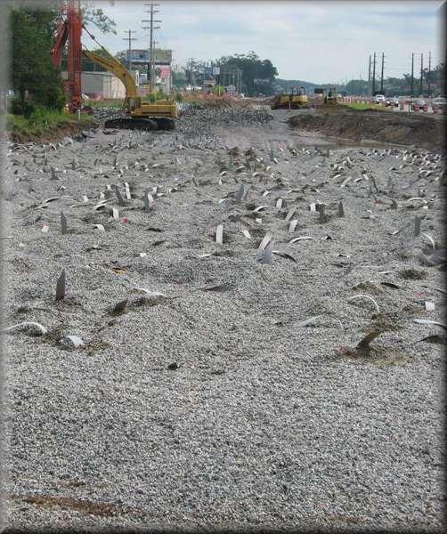

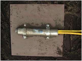
43 PVD Installation 3 Million LF
44 PVD Installation S s = 3 and 4 PVD PVD Triangular Installation Pattern PVD 2 Drainage Sand Layer Geotextile Separator Fabric


45 PVD Installation Obstructions!!! 309,000 LF Predrilling PVD Installation


46 MSE Walls Permanent MSE Walls Two-Stage Construction Three-Stage Construction (w/drainage Structures) Temporary MSE Walls (Welded Wire Mesh Facing) 30,500 SF 51,500 SF
")


47 Deep Soil Mixing Columns (Overlap Block Pattern) 35,600 CY Seismic Slope Stabilization Shear Key Improved Performance of Bridge Abutment Foundations 2013


48 Deep Soil Mixing Columns (Overlap Block Pattern) Longitudinal DSM Bridge Abutment DSM Longitudinal DSM
49 10 Feet Min. Deep Soil Mixing Test Sections 10 Feet Min Test LCC No Test Pile 1 (HP 14x117) DSM-LCC Test Section 1 (Block Type Pattern) Test LCC Sampling Quadrants DSM-LCC Test Section 2 (Single Line Pattern) Legend Test Lime-Cement Columns (Test LCC)
50 CONSTRUCTION SEQUENCE
51 Project Construction Stages (North Abutment ) Ramp D Stage 3 Bridge Approach Embankment Stage 4 Ramp B Stage 2
52 Bridge Abutment Construction (North Abutment End Bent 7)
53 Bridge Abutment Construction Bridge Wing Wall Vertical Slip Joints MSE Wall Concrete Panel Facing DSM-LCC Block Type Pattern MSE Wall Leveling Pad HP 14x Piles/row PVD (Wick Drains) 30 Feet
54 LIGHTWEIGHT AGGREGATE BORROW PROPOSED

55 Lightweight Aggregate Borrow (Proposed New Material)


56 Lightweight Aggregate Borrow (Rotary Kiln Produced)
 50 40 30 Section 713 MSE Wall 20 10 0 1000.000 100.000 10.000 Grain Size (mm) 1.000 0.100 0.")
57 % Passing Grain Size Curve 1 ½" ¾" 3/ 8" # 4 # 30 # 40 # 100 # Big River Proposed Lightweight Aggregate LWF Min LWF Max 713 Min 713 Max 70 BR Min BR Max 60 LWA (S15922) Section 713 MSE Wall Grain Size (mm)
58 Lightweight Aggregate Density Properties Lightweight Aggregate Borrow Soil Properties (Item ) Soil Properties SCDOT Specified Proposed Minimum: Dry Unit Weight, g Dry (pcf) * Maximum: Dry Unit Weight, g Dry (pcf) ** Minimum: Wet Unit Weight, g Wet (pcf) ** Maximum: Wet Unit Weight, g Wet (pcf) ** * 95% Maximum Density ** Estimated based on laboratory testing submitted by Big River Industries
59 Lightweight Aggregate Borrow (Proposed New Material Differences) Higher Fines Content Lower Dry Unit Weight Total Unit Weight 15% Less Than Designed High Absorption Gradation Coarse Sand Vs. Aggregate Compaction Verification Required by SCDOT


60 Test Section #1 (Dry)


61 Test Section #1 (Wet)

62 Granular Surcharge & Lightweight Aggregate Borrow Granular Surcharge Granular Backfill Lightweight Aggregate Borrow Material Design Team Performed a Redesign Reduced the Lightweight Quantity by 15% Saved Horry County $2 Million
63 COMPACTION VERIFICATION
64 Lightweight Aggregate Borrow Compaction Verification Challenges Interparticle Voids Particle Absorbed Moisture Particle Ceramic Solids Particle Pore Voids Interparticle Moisture
65 Compaction Control Laboratory Compaction Curves Target 95% Max Dry Density = 43 pcf Moisture Content Varied Significantly for the same Dry Density


66 Test Section #2 Compaction Control Test Section #2 - Evaluate Compaction Control Methods Compaction Control - 1 Cu. Ft. Steel Box, Calibrated Nuclear Density Gauge, Sand Cone, and EDG.
67 Test Section #2 Field Testing Set NG-1 MT-1 MT-3 MT-2 MC-1 MT-4 SC = Sand Cone NG = Nuclear Gauge EDG = Electric Density Gauge STB = Steel Test Box SC-1 EDG-1 SC-2 MTB-1 MC-2 MTB-2 MTB-3 STB NG-2 MT-5 SC-3 EDG-2 MC-3 MT-7 EDG-3 MT-6 MT-8 Compacted Lightweight Aggregate Borrow NG-3 MC = Hot Plate & Oven Moisture Content MT = Moisture Tester MTB = Moisture Tester in Steel Box


68 Test Section #2 1 Cu. Ft Steel Box (Control Test)
69 Test Section #2 Field Testing Sets Test Set Moisture Added Process Compaction Effort 1 As delivered Compact 3 passes with vibratory roller 2 No Water Added Scarify & Compact 4 passes with a vibratory roller 3 Added Water - 1 Pass Scarify & Compact 8 passes with a walk behind vibratory flat plate compactor 4 Added Water - 2 Passes Scarify & Compact 3 passes with a vibratory roller 5 No Water Added Scarify & Compact 4 passes with a vibratory roller 6 No Water Added Scarify & Compact 8 passes with a vibratory roller Added Water- 2.5 Passes Scarify & Compact 7 (Saturated) 3 passes with a vibratory roller


70 Test Section #2


71 Compaction Control Calibrated Nuclear Gauge
72 LIGHTWEIGHT AGGREGATE SUPPLY & DELIVERY


73 Big River Industries Livingston, AL Myrtle Beach, SC

74 Big River Industries 500 Mile Radius Livingston, AL

75 Livlite Big River Industries


76 Lightweight Aggregate Borrow Pre-conditioning


77 Lightweight Aggregate Borrow Pre-conditioning

78 Ramp B Construction Pre-conditioned Lightweight Aggregate CONSTRAINTS

79 Ramp B Construction Pre-conditioned Lightweight Aggregate CONSTRAINTS
80 GEOTECHNICAL INSTRUMENTATION
81 Geotechnical Instrumentation Settlement Monitoring 4 Magnetic Extensometer 10 Settlement Plates 12 VW Settlement Sensors 17 VW Piezometers 2 VW Data Collection Centers Slope Stability 6 Slope Inclinometers


82 VW Magnetic Extensometers Pre-Assembled ME Spider Magnet Telescoping Section
83 Settlement (Inches) Elevation (feet) Embankment Height (Feet) Instrumentation Results ME Extensometers Settlement (Inches) /1/ /7/ /14/ /19/ /21/ /27/ /29/2011 1/4/2012 1/12/2012 1/18/2012 1/25/2012 2/1/ Embankment Construction Finished Embankment Height Top of LWF Datum Magnet Days SA-1 SA-2-70


84 VW Piezometers

85 Instrumentation Results VW Piezometers


86 Settlement Plates


87 VW Settlement Sensors


88 VW Settlement Sensor Data Collection
89 Automated Data Collection VW Data Collection Center VW Settlement Sensors Cellular Phone Database Server VW Device Connection Board VW Data Collection Logger Internet VW Piezometers Power Source (Solar Power) Engineer

90 VW Device Connections VW Devices connected to 16-channel Board


91 Data Collection Center isite Logger with Solar Controller Charging Battery Inside DCC Enclosure & Solar Panel

92 X-Section End Bent 1 (South Bridge Abutment, )
93 Settlement Transverse Profile (South Bridge Abutment ) Ramp A
94 Settlement Embankment Height (Feet) Ramp A Settlement Measurements Embankment Construction Finished US-17 Bypass Settlement Sensor A-VWSS Surcharge Removed Days Since VWSS Installed Embankment Height Lightweight Fill Height SS Reading No. 1-5:00 SS Reading No. 2-12:00 SS Reading No. 3-19:00 SS Reading No. 4-23:00
95 Settlement Transverse Profile (South Bridge Abutment ) Ramp C
96 Settlement (Inches) Embankment Height (Feet) Ramp C Settlement Measurements Emankment Construction Finished Surcharge Removed Embankment Height Lightweight Fill Height SS Reading No. 1-5:00 SS Reading No. 2-11: Days Since VWSS Installed

97 X-Section End Bent 7 (North Bridge Abutment, )
98 Settlement Transverse Profile (North Bridge Abutment ) Ramp B
99 Settlement Embankment Height (Feet) Ramp B Settlement Measurements Embankment Construction Finished Settlement Sensor Surcharge Removal Days Since VWSS Installed Embankment Height Lightweight Fill Height SS Reading No. 1-5:0:0 SS Reading No. 2-12:0:0 SS Reading No. 3-19:0:0 SS Reading No. 4-23:0:0
100 Settlement Transverse Profile (North Bridge Abutment ) Ramp D
101 Settlement Embankment Height (Feet) Ramp D Settlement Measurements Emankment Construction Finished Surcharge Removed Days Since VWSS Installed Embankment Height Lightweight Fill Height SS Reading No. 1-5:00 SS Reading No. 2-12:00 SS Reading No. 3-19:00
102 PROJECT CONSTRUCTION
103 Traffic Control Stage 2 Ramp A Ramp B MSE Walls Lightweight Aggregate Borrow Material 2, and 3 Granular Surcharge (Normal Weight) 3 and 4 Triangular Spacing PVD Geotechnical Instrumentation

104 Traffic Control Stage 2 Ramp A Construction US 17 Bypass NB

105 Traffic Control Stage 2 Ramp B Construction US 17 Bypass NB


106 Construction Ramp A & B (PVD Installation)

107 Construction Ramp A & B (PVD Installation)

108 Construction Ramp A & B (MSE Wall Embankment Construction)

109 Construction Ramp A & B (MSE Wall Embankment Construction)
110 Sloped Lightweight Aggregate Embankment Lightweight Aggregate Borrow Material 4 Feet Long Biaxial Geogrids Placed on 2 Feet Vertical Spacing 2 Feet Thick Cover of Borrow Silty or Clayey Soil Materials

111 Sloped Lightweight Aggregate Embankment
112 Traffic Control Stage 3 Ramp C Ramp D MSE Walls Lightweight Aggregate Borrow Material 1, 2, and 4 Granular Surcharge (Normal Weight) 3 and 4 Triangular Spacing PVD Geotechnical Instrumentation
")


113 Traffic Control Stage 3 (Ramps A & B Completed) Ramps C/D Under Construction -Stage 3 Existing NB = Stage 3 SB Constructed Ramps A/B (Completed Stage 2)
 Traffic on Ramp A Existing NB =")
114 Traffic Control Stage 3 (Ramps A & B Completed) Traffic on Ramp A Existing NB = Stage 3 SB

115 Construction Ramp C Traffic on Ramp C US 17 Bypass SB


116 Construction Ramp C Traffic on Ramp C US 17 Bypass SB

117 Construction Ramp C US 17 Bypass SB Ramp D

118 Construction Ramp D Traffic on Ramp B Ramp D
119 Traffic Control Stage 4 South Bridge Approach Backgate Bridge North Bridge Approach MSE Walls Lightweight Aggregate Borrow Material 1, 2, and 3 Granular Surcharge (Normal Weight) 3 Triangular Spacing PVD Geotechnical Instrumentation Bridge Abutment DSM (South 30 x 133 x 50 deep North 30 x 141 x 70 deep ) Longitudinal DSM (South 5 Wide / North 8 Wide)
120 CLOSING
121 Project Status Preliminary Engineering: Right of Way Acquisition: Construction: Approximately 33% complete

122 Under Construction Traffic Stage 3 Ramps C/D have been constructed and will be ready to be paved in the near future Traffic Stage 4 Scheduled to Start April 2013 Deep Soil Mixing : Test Section / Test Pile / Production Bridge Abutment Foundation Construction Construct Bridge Approach Embankment & MSE Walls
123 Closing Geotechnical techniques are speeding up construction Positive feedback regarding construction traffic congestion and shifts Estimated project completion: Fall 2014 Project Cost $75.8 Million

124 Thank You Any Questions?
Grade separated interchange at the intersection of U.S. Hwy 17 Bypass and Farrow Parkway
 Grade separated interchange at the intersection of U.S. Hwy 17 Bypass and Farrow Parkway Jeff Sizemore, P.E. Geotechnical Design Support Engineer SCDOT Ed Tavera, P.E. Principal Geotechnical Engineer Geoengineers
Performance of Mechanically Stabilized Earth walls over compressible soils
 Performance of Mechanically Stabilized Earth walls over compressible soils R.A. Bloomfield, A.F. Soliman and A. Abraham The Reinforced Earth Company, Vienna, Virginia, USA ABSTRACT: Two projects have recently
ODOT Design & Construction Requirements for MSE Walls
 ODOT Design & Construction Requirements for MSE Walls Peter Narsavage, P.E. Foundation Engineering Coordinator Ohio Department of Transportation Office of Structural Engineering 2006 Ohio Transportation
SPECIFICATIONS FOR PRECAST MODULAR BLOCK RETAINING WALL SYSTEM (revised 5/8/7)
") Page 1 of 7 STONE STRONG SYSTEMS SPECIFICATIONS FOR PRECAST MODULAR BLOCK RETAINING WALL SYSTEM (revised 5/8/7) PART 1: GENERAL 1.01 Description A. Work includes furnishing and installing precast modular
Page 1 of 7 STONE STRONG SYSTEMS SPECIFICATIONS FOR PRECAST MODULAR BLOCK RETAINING WALL SYSTEM (revised 5/8/7) PART 1: GENERAL 1.01 Description A. Work includes furnishing and installing precast modular
MSE WALLS CASE STUDIES. by John G. Delphia, P.E. TxDOT Bridge Division Geotechnical Branch
 MSE WALLS CASE STUDIES by John G. Delphia, P.E. TxDOT Bridge Division Geotechnical Branch COMMON RETAINING WALL TYPES CONCRETE BLOCK MSE TEMPORARY EARTH SPREAD FOOTING Gabions Drilled Shaft Soil Nail Tiedback
Ground improvement support using Confined aggregate piers in soft soil. Brian Metcalfe, P.E. Director of Engineering Geopier Foundation Company
 Ground improvement support using Confined aggregate piers in soft soil Brian Metcalfe, P.E. Director of Engineering Geopier Foundation Company OUTLINE Ground improvement historical perspective Confined
SCG INTERNATIONAL TRINIDAD AND TOBAGO LIMITED COUVA CHILDREN S HOSPITAL
 SCG INTERNATIONAL TRINIDAD AND TOBAGO LIMITED COUVA CHILDREN S HOSPITAL GEOTECHNICAL CONSULTANT Prepared by Checked by Approved by Mr. C Allen Dr. Derek Gay Dr. Derek Gay Signature Date Signature Date
or (800)
") WWW.CELL-CRETE.COM or (800) 669-0433 CALIFORNIA (Lic #243404), OREGON, WASHINGTON, NEVADA, UTAH, IDAHO, MONTANA, ARIZONA, HAWAII, ALASKA, WESTERN CANADA Re: Cellular Concrete as Engineered Fill I m pleased
WWW.CELL-CRETE.COM or (800) 669-0433 CALIFORNIA (Lic #243404), OREGON, WASHINGTON, NEVADA, UTAH, IDAHO, MONTANA, ARIZONA, HAWAII, ALASKA, WESTERN CANADA Re: Cellular Concrete as Engineered Fill I m pleased
MECHANICALLY STABILIZED EARTH (MSE) WALL SYSTEMS
 WALL SYSTEMS") DRAINAGE SOLUTIONS SINCE 1908 MECHANICALLY STABILIZED EARTH (MSE) WALL SYSTEMS PERMANENT AND TEMPORARY ENGINEERED WALL SOLUTIONS ECONOMICAL DURABLE VERSATILE ARMTEC.COM MSE RETAINING WALLS Armtec Mechanically
DRAINAGE SOLUTIONS SINCE 1908 MECHANICALLY STABILIZED EARTH (MSE) WALL SYSTEMS PERMANENT AND TEMPORARY ENGINEERED WALL SOLUTIONS ECONOMICAL DURABLE VERSATILE ARMTEC.COM MSE RETAINING WALLS Armtec Mechanically
REPORT STATUS: DATE: Report n :
 REPORT: Expanded clay LWA in CEA Lightweight fill and thermal insulation products for civil engineering applications. Installation and structural quality control on site. STATUS: Technical report DATE:
A CASE HISTORY ON DESIGN, CONSTRUCTION, AND PERFORMANCE OF STONE COLUMN GROUND IMPROVEMENT BENEATH AN MSE EMBANKMENT
 A CASE HISTORY ON DESIGN, CONSTRUCTION, AND PERFORMANCE OF STONE COLUMN GROUND IMPROVEMENT BENEATH AN MSE EMBANKMENT Karen Dawson, P.E. and Seungcheol Shin, Ph.D., P.E., CH2M HILL, Bellevue, WA, USA Suthan
SECTION EXCAVATION AND EMBANKMENT. B. Subbase Grading A samples for gradation analysis.
 PART 1 GENERAL 1.1 DESCRIPTION A. The WORK under this Section includes providing all labor, materials, tools and equipment necessary for excavation and embankment construction to the lines, grades and
GEOTECHNICAL RESISTANCE FACTORS
 Chapter 9 GEOTECHNICAL RESISTANCE FACTORS Final SCDOT GEOTECHNICAL DESIGN MANUAL 9-i Table of Contents Section Page 9.1 Introduction... 9-1 9.2 Soil Properties... 9-2 9.3 Resistance Factors for LRFD Geotechnical
Chapter 15 SHALLOW FOUNDATIONS
 Chapter 15 SHALLOW FOUNDATIONS Final SCDOT GEOTECHNICAL DESIGN MANUAL June 2010 SCDOT Geotechnical Design Manual Shallow Foundations Table of Contents Section Page 15.1 Introduction...15-1 15.2 Design
RIGID INCLUSIONS. Rigid Inclusions offer an economical approach for building on sites underlain by soft soil.
 H A Y W A R D B A K E R I N C. RIGID INCLUSIONS Rigid Inclusions offer an economical approach for building on sites underlain by soft soil. Above: HBI installed Rigid Inclusions on a congested downtown
Anchorplex retaining wall construction guide. Building. Anchorplex. Retaining Wall Systems
 Anchorplex retaining wall construction guide Building Anchorplex Retaining Wall Systems Table of Contents and ow to Use This Guide table of contents ow to Use This Guide. 2 About the Anchorplex System.
ENGINEERING DIRECTIVE
 Number: E-95-001 Date: 2/2/95 ENGINEERING DIRECTIVE Ross B. Dindio (Signature on Original) CHIEF ENGINEER The purpose of this engineering directive is to formally notify ALL Department engineering personnel
CE 240 Soil Mechanics & Foundations Lecture 4.1. Soil Compaction: Field work (Das, Ch. 5)
") CE 240 Soil Mechanics & Foundations Lecture 4.1 Soil Compaction: Field work (Das, Ch. 5) Outline of this Lecture 1. Factors controlling degree of compaction 2. Compaction field work 3. Compaction quality
CE 240 Soil Mechanics & Foundations Lecture 4.1 Soil Compaction: Field work (Das, Ch. 5) Outline of this Lecture 1. Factors controlling degree of compaction 2. Compaction field work 3. Compaction quality
AMERDRAIN. Prefabricated Vertical Soil Drainage Systems ICK. Soil drainage method for accelerating settlement through vertical drainage
 AMERDRAIN Prefabricated Vertical Soil Drainage Systems Soil drainage method for accelerating settlement through vertical drainage MERICAN ICK RAIN CORPORATION INTRODUCTION The problem Historically, the
DESIGNING AND CONSTRUCTION OF T-WALL RETAINING WALL SYSTEM
 Istanbul Bridge Conference August 11-13, 2014 Istanbul, Turkey DESIGNING AND CONSTRUCTION OF T-WALL RETAINING WALL SYSTEM T. C. NEEL and K.BOZKURT ABSTRACT This work shall consist of the design, manufacture
I-35W Retaining Wall Design Exhibit A - Draft Scope of Work
 Background MnDOT, Metro Transit, Hennepin County, and the City of Minneapolis are in the process of developing a project for Interstate 35W between 43 rd Street in Minneapolis and 15 th Street in Minneapolis.
SCDOT Geotechnical Manual Updates. Nicholas E. Harman, MS PE
 SCDOT Geotechnical Manual Updates Nicholas E. Harman, MS PE Background GDM version 1.0 introduced in August 2008 Chapters 1 to 12 Appendix A GDM version 1.1 introduced in June 2010 Chapters 13 to 26 Appendices
GEOTECHNICAL LRFD DESIGN
 Chapter 8 GEOTECHNICAL LRFD DESIGN Final SCDOT GEOTECHNICAL DESIGN MANUAL August 2008 Table of Contents Section Page 8.1 Introduction... 8-1 8.2 LRFD Design Philosophy... 8-2 8.3 Limit States... 8-3 8.4
by Dr. Mark A. Ketchum, OPAC Consulting Engineers for the EERI 100 th Anniversary Earthquake Conference, April 17, 2006
 Principles of Earthquake Engineering of Bridges Part 1: Principles & Approach by Dr. Mark A. Ketchum, OPAC Consulting Engineers for the EERI 100 th Anniversary Earthquake Conference, April 17, 2006 Presentation
October 1, Re: Contract ID A Plans, Proposal, EBS, Questions & Answers October 8, 2013 Letting
 October 1, 2013 Dear Prospective Bidders: Re: Contract ID 26.036775A Plans, Proposal, EBS, Questions & Answers October 8, 2013 Letting The Contractor is hereby advised of modifications to the bid documents.
Experience of a Large Scale Unintentionally Long Surcharge on Organic Soils
 Experience of a Large Scale Unintentionally Long Surcharge on Organic Soils Ying Liu, Ph.D., P.E., Senior Engineer, Group Delta Consultants, Inc., 37 Amapola Ave., Suite 212, Torrance, CA. Email: yingl@groupdelta.com
MSE Walls Problems and Solutions
 MSE Walls Problems and Solutions Peter Narsavage, P.E. Foundation Engineering Coordinator Ohio Department of Transportation Office of Structural Engineering ODOT Geotechnical Workshop April 11, 2006 Problems
Numerical Modeling of Dynamic Soil-Structure Interaction in Bridges with HP Driven Piles
 Numerical Modeling of Dynamic Soil-Structure Interaction in Bridges with HP Driven Piles Yu Bao, Andrew Rietz and Steven Halewski, Rochester Institute of Technology, Rochester, NY, USA HP-Pile foundations
Geotechnical Specification and Construction Update
 Geotechnical Specification and Construction Update Steve Slomski, P.E. Office of Construction Administration Topics 2016 C&MS Revisions Supplemental Specifications & Supplements Revisions & Additions Construction
2. Pavement Materials: Consist of flexible or rigid pavements, typically HMA or PCC, respectively, or a composite of the two.
 Design Manual Chapter 6 - Geotechnical 6C - Pavement Systems 6C-1 Pavement Systems A. General Information This section addresses the importance of pavement foundations and the potential for pavement problems
Introduction to Foundations on Fill and Backfilling
 Introduction to Foundations on Fill and Backfilling Course No: G01-003 Credit: 1 PDH J. Paul Guyer, P.E., R.A., Fellow ASCE, Fellow AEI Continuing Education and Development, Inc. 9 Greyridge Farm Court
ICC-ES Evaluation Report Issued July 1, 2011 This report is subject to renewal in one year.
 ICC-ES Evaluation Report ESR-1959 Issued July 1, 2011 This report is subject to renewal in one year. www.icc-es.org (800) 423-6587 (562) 699-0543 A Subsidiary of the International Code Council DIVISION:
Description. This work shall consist of furnishing materials and placement of modular block wall constructed in accordance with
 MODULAR CONCRETE BLOCK RETAINING WALL WITH GROUND REINFORCING The Standard Specifications are revised as follows: 732-R-310r 1of 11 Rev. 12-03-03 SECTION 105, AFTER LINE 48, INSERT AS FOLLOWS: When constructing
Improving Engineering Properties of Soft Soil Using Preloading and Prefabricated Vertical Drains
 Volume 1, Issue 2, October-December, 2013, pp. 08-12, IASTER 2013 www.iaster.com, Online: 2347-2855, Print: 2347-8284 ABSTRACT Improving Engineering Properties of Soft Soil Using Preloading and Prefabricated
SECTION SPECIFICATION FOR STONEBRIDGE RETAINING WALL SYSTEM
 SECTION 32 32 23 SPECIFICATION FOR STONEBRIDGE RETAINING WALL SYSTEM PART 1: GENERAL 1.01 Scope Work includes furnishing all materials, labor, equipment, and supervision to install a Stonebridge segmental
Behavior of Reinforced Embankment on Soft Ground with and without Jet Grouted Soil-Cement Piles
 Behavior of Reinforced Embankment on Soft Ground with and without Jet Grouted Soil-Cement Piles by 1 Dennes T. Bergado and 2 Glen A. Lorenzo 1 Professor and 2 Doctoral Candidate, respectively Geotechnical
CHAPTER 3 CONSTRUCTION AND TESTING OF SUBGRADE
 CHAPTER 3 CONSTRUCTION AND TESTING OF SUBGRADE WHAT IS SUBGRADE? SUBGRADE EMBANKMENT FOUNDATION The top surface of an embankment or cut section, shaped to conform to the typical section upon which the
Experiences on embankment fill in land expressway over soft ground
 Second International Seminar on the Design & Construction of the Second Penang Bridge Experiences on embankment fill in land expressway over soft ground Prepared by ; AZMI MADMARJUKI Project Location JAMBATAN
This paper describes the salient features of a
 Geogrid Reinforced Soil Walls with Welded Wire Mesh Facing to Retain the Approaches to a Flyover This paper describes the salient features of a project wherein geogrid reinforced soil walls with a welded
GEOSYNTHETICS ENGINEERING: IN THEORY AND PRACTICE
 GEOSYNTHETICS ENGINEERING: IN THEORY AND PRACTICE Prof. J. N. Mandal Department of civil engineering, IIT Bombay, Powai, Mumbai 400076, India. Tel.022-25767328 email: cejnm@civil.iitb.ac.in Module - 9
SECTION PERMEABLE INTERLOCKING CONCRETE UNIT PAVEMENT
 SECTION 32 14 13 19 PERMEABLE INTERLOCKING CONCRETE UNIT PAVEMENT SECTION 32 14 13 19 PERMEABLE INTERLOCKING CONCRETE UNIT PAVEMENT PART 1 - GENERAL 1.1 SUMMARY A. Section Includes: 1. Permeable Articulating
PROPOSED STOCK PILE YARD PHASE 1 SITE: MYRA FALLS MINE
 SITE NOT TO SCALE 635-8-STOCKPILEPHGA- 00 SHEET: OF DRAWING INDEX: SHEET 2 OF 0 - NOTES SHEET 3 OF 0 - PLAN VIEW :000 SHEET 4 OF 0 - PLAN VIEW :000 WITH REFERENCE SHEET 5 OF 0 - PLAN VIEW :500 SHEET 6
Simple Design Alternatives to Improve Drainage and Reduce Erosion at Bridge Abutments
 Simple Design Alternatives to Improve Drainage and Reduce Erosion at Bridge Abutments Mohamed M. Mekkawy Iowa State University 405 Town Engineering Building Ames, IA 50011-3232 meks@iastate.edu David J.
Study of Various Techniques for Improving Weak and Compressible Clay Soil under a High Earth Embankment
 MATEC Web of Conferences 11, 03006 ( 2014) DOI: 10.1051/ matecconf/ 20141103006 C Owned by the authors, published by EDP Sciences, 2014 Study of Various Techniques for Improving Weak and Compressible Clay
Well Road Project Accelerated Bridge Construction Using Self-Propelled Modular Transporters (SPMT s) By: Mark Bucci, P.E.
 By: Mark Bucci, P.E.") Well Road Project Accelerated Bridge Construction Using Self-Propelled Modular Transporters (SPMT s) By: Mark Bucci, P.E. Presentation Outline Project History Project Scope Construction Alternatives Plan
Well Road Project Accelerated Bridge Construction Using Self-Propelled Modular Transporters (SPMT s) By: Mark Bucci, P.E. Presentation Outline Project History Project Scope Construction Alternatives Plan
Applications of Waste Tire Products in Civil Engineering
 Applications of Waste Tire Products in Civil Engineering Introduction to Civil Engineering Design CSU, Chico Introduction Background Benefits of Using TDA Civil Engineering Applications Lightweight Fill
Topic #4 Soil Compaction
 Topic #4 Soil Compaction What is Compaction? A simple ground improvement technique, where the soil is densified through external compactive effort. Compactive Effort + Water = 2 Compaction and Phase Diagram
5-20 FOUNDATION REPORT/GEOTECHNICAL DESIGN
 5-20 FOUNDATION REPORT/GEOTECHNICAL DESIGN REPORT CHECKLIST FOR EARTH RETAINING SYSTEMS Introduction This checklist was developed to assist the geotechnical project professionals in preparing the Foundation
INSPECTION GUIDE FOR SEGMENTAL RETAINING WALLS TEK 18-11B
 An information series from the national authority on concrete masonry technology INSPECTION GUIDE FOR SEGMENTAL RETAINING WALLS TEK 18-11B Quality Assurance and Testing (2012) INTRODUCTION Segmental retaining
CONCRETE SEGMENTAL RETAINING WALL SYSTEM
 CONCRETE SEGMENTAL RETAINING WALL SYSTEM PART 1: GENERAL SPECIFICATIONS 1.01 Work Included A. Work shall consist of furnishing and constructing a Rockwood Classic 8, Classic 6 and Legend unit segmental
Chapter 18 EARTH RETAINING STRUCTURES
 Chapter 18 EARTH RETAINING STRUCTURES Final SCDOT GEOTECHNICAL DESIGN MANUAL June 2010 SCDOT Geotechnical Design Manual Earth Retaining Structures Table of Contents Section Page 18.1 Introduction...18-1
Structural - Engineering Review Checklist
 Structural - Engineering Review Checklist Project: List Corridor Criteria ID Review Priority (H,M,L) TOPICS S-_-## Structural Design Codes, Manuals and Specifications 6.1.0 REFERENCES DESIRED Criteria
GEOSYTHETIC SLOPE SPEC-V0704rev.doc STANDARD SPECIAL PROVISION FOR GEOSYNTHETIC REINFORCED SLOPE CONSTRUCTION
 GEOSYTHETIC SLOPE SPEC-V0704rev.doc STANDARD SPECIAL PROVISION FOR GEOSYNTHETIC REINFORCED SLOPE CONSTRUCTION I. DESCRIPTION - This work consists of furnishing the required materials and construction of
2.1 Backfill - General
 2.1 Backfill - General Excavations are made for the purpose of constructing bridge substructure elements, and consequently requiring competent backfill material. The backfill material must be adequately
LIGHTWEIGHT FILL DESIGN GUIDANCE
 Preferred Design Procedure LIGHTWEIGHT FILL The Federal Highway Administration (FHWA) and National Cooperative Highway Research Program (NCHRP) have two documents for this technology that contain design
Ground Improvement for Mitigation of Failure Risks to Existing Embankment Dams
 Ground Improvement for Mitigation of Failure Risks to Existing Embankment Dams by James K. Mitchell, Sc.D., P.E., Dist. M.ASCE University of Alberta, Edmonton, Alberta October 6, 2010 1 SCOPE OF THE LECTURE
JOB BB0113 SHELL LAKE STR. & APPRS. (S) MARCH 10, 2015 LETTING QUESTIONS PREVIOUSLY ASKED UNDER JOB BB0106.
 MARCH 10, 2015 LETTING QUESTIONS PREVIOUSLY ASKED UNDER JOB BB0106.") JOB BB0113 SHELL LAKE STR. & APPRS. (S) MARCH 10, 2015 LETTING QUESTIONS PREVIOUSLY ASKED UNDER JOB BB0106. There are notes in the plans regarding driving the test pile without the use of a follower. The
JOB BB0113 SHELL LAKE STR. & APPRS. (S) MARCH 10, 2015 LETTING QUESTIONS PREVIOUSLY ASKED UNDER JOB BB0106. There are notes in the plans regarding driving the test pile without the use of a follower. The
StormTech Construction Guide
 A division of StormTech solid end caps and pre-cored end caps StormTech chambers StormTech manifolds and fittings Acceptable fill materials per Table 1 Woven and non-woven geotextiles 80-7 DC REQUIRED
aggregate piers / vscs
 aggregate piers / vscs 1 2 HT1.0 1-1 1-2 1' - 1" 34' - 0" 16' - 11" 1' - 1" 13' - 10" BOF 817' - 6" (TYPICAL WITHIN HATCHED REGION) 1-17 1-32 1-47 1-62 1-3 1-18 1-33 1-48 1-63 1-4 1-19 1-34 1-49 1-64 1-5
Construction Procedures
 Construction Procedures 2014 Rev. 1.6 1 Introduction This manual presents the methods and procedures necessary for the proper erection of a LOCK+LOAD retaining wall. problems later during the service life
Design of Geofoam Embankment for the. Steven F. Bartlett, Ph.D., P.E. Research Project Manager, UDOT
 Design of Geofoam Embankment for the I-15 Reconstruction Steven F. Bartlett, Ph.D., P.E. Research Project Manager, UDOT I-15 Reconstruction - Quick Facts Single Largest Highway Contract t in U.S. 17 Miles
Student Services & Classroom Addition
 SECTION 321216 - ASPHALT PAVING PART 1 GENERAL 1.1 RELATED DOCUMENTS A. Drawings and general provisions of the Contract, including General and Supplementary Conditions and Division 01 Specification Sections,
1/26/2015 DETAILS CIP DETAIL EXAMPLES WHY SIMPLIFY DETAILS? CIP DETAIL EXAMPLES DETAILING FOR SIMPLICITY
 Detailing of ABC Bridges for Simplicity and Durability Michael P. Culmo, P.E. CME Associates, Inc. East Hartford, CT DETAILS This presentation contains many preferred details My favorite details will be
TABLE OF CONTENTS. Background of Existing Facility 3. Proposed Work 4
 TABLE OF CONTENTS SECTION PAGE Background of Existing Facility 3 Proposed Work 4 Objective of this Report 4 Required Data 4 Pavement Design Procedure 5 Other Data Requirements 7 Pavement Structures 8 Pavement
Design Considerations. Pursuing Dynamic Compaction. waste considered. Pursuing Dynamic Compaction. Page 1 of6
 Page 1 of6 waste considered. Pursuing Dynamic Compaction Waste Age Ali Khatami, Ph.D., Bruce Clark and Myles Clewner of SCS Engineers Fri, 2013-07-19 16:26 Rapid growth of development in metropolitan areas
Design of Rigid Pavements
 Traffic and Highway Engineering (ІІ) CVL 4324 Chapter 20 Design of Rigid Pavements Dr. Sari Abusharar Assistant Professor Civil Engineering Department Faculty of Applied Engineering and Urban Planning
Mix Design & Construction -1-
 Mix Design & Construction -1- AGENDA RCC Mix Design RCC Mix Production RCC Construction Process -2- THE FINAL SURFACE TYPE WILL DICTATE THE NECESSARY TECHNIQUES & EQUIPMENT NEEDED TO BE SUCCESSFUL Natural
Bureau of Materials Materials Approval Procedures
 Bureau of Materials Materials Approval Procedures MAP Number: 116-15 Effective Date: April 1, 2015 Approved By: Eileen Sheehy PROCEDURE FOR APPROVAL OF MECHANICALLY STABILIZED EARTH (MSE) RETAINING WALL
GEOTECHNICAL STUDY PROPOSED CONCRETE ROADWAY TIKI ISLAND COMMUNITY GALVESTON COUNTY, TEXAS PROJECT NO E
 GEOTECHNICAL STUDY PROPOSED CONCRETE ROADWAY TIKI ISLAND COMMUNITY GALVESTON COUNTY, TEXAS PROJECT NO. 15-945E TO VILLAGE OF TIKI ISLAND TIKI ISLAND, TEXAS BY SERVICING TEXAS, LOUISIANA, NEW MEXICO, OKLAHOMA
SPECIFICATION FOR REINFORCED SOIL WALL
 SPECIFICATION FOR REINFORCED SOIL WALL 1.0 EXTENT OF WORK The work shall consist of Reinforced Soil walls built in accordance with this specification and in conformity with the lines, levels and details
Applied GeoScience, Inc Hammond Dr., Suite 6 Schaumburg, Illinois
 AGI Project No. 13-276 Subsurface Investigation Report For the Proposed New Retail Center 9601 South Pulaski Road Evergreen Park, Illinois Prepared for Mr. Feras Sweis FHS Design + Build LLC 2010 West
Long-Term Instrumentation Program to Monitor Various Geo-Technologies Used on the I-15 Reconstruction Project, Salt Lake City, Utah
 Farnsworth and Bartlett Long-Term Instrumentation Program to Monitor Various Geo-Technologies Used on the I-15 Reconstruction Project, Salt Lake City, Utah By Clifton Farnsworth Geotechnical Division Utah
Tasman Retaining Wall System
 Tasman Retaining Wall System The Tasman Retaining Wall System incorporates purpose made corners and capping units to provide classical reconstructed stone retaining walls for any landscape situation. From
Table of Contents. July
 Table of Contents 36.1 General... 3 36.1.1 Bridge or Culvert... 3 36.1.2 Box Culvert Size Restrictions... 4 36.1.3 Stage Construction for Box Culverts... 4 36.2 Dead Loads and Earth Pressure... 5 36.3
CHAPTER 23 PILES TABLE OF CONTENTS TABLE OF CONTENTS. 23.TOC Table of Contents... 30Jan Introduction... 30Jan2018
 CHAPTER 23 TABLE OF CONTENTS FILE NO. TITLE DATE TABLE OF CONTENTS 23.TOC Table of Contents... 30Jan2018 23.00 Introduction... 30Jan2018 DESIGN GUIDE FOR LATERALLY UNSUPPORTED 23.01-1 Notes and Definitions...
Alberta Bridge Inventory STANDARD BRIDGE & CULVERT COMPONENTS. Standard Bridges. Typical Bridge Components. In Alberta there are about 13,300 bridges.
 STANDARD BRIDGE & CULVERT COMPONENTS Alberta Bridge Inventory In Alberta there are about 13,300 bridges. Types of bridges in Alberta: Standard bridges 3521 (26%) Bridge size culverts 8348 (63%) Major bridges
Redi Rock Specification and Installation Manual
 Redi Rock Specification and Installation Manual 1.0 General Scope This Specification covers the Design, Materials and Installation of Redi Rock modular block Retaining and Freestanding Wall systems as
Section 25 Aggregate Subbase
 Black text from standard FAA spec Strikeout text deletions from FAA standard spec Blue text additions to FAA standard spec Red text notes to the Engineer/won t appear in spec I. DESCRIPTION A. GRANULAR
Ground Improvement Techniques: Dynamic Compaction Martin Larisch & Tim Pervan
 Ground Improvement Techniques: Dynamic Compaction Martin Larisch & Tim Pervan INSERT DATE HERE Ground Improvement - What is it? Ground Improvement = Black Box? Ground Improvement - Introduction Ground
PDPI 2015 STATIC ANALYSIS LATERALLY LOADED PILE DESIGN. Chapter 9
 PDPI 2015 STATIC ANALYSIS LATERALLY LOADED PILE DESIGN Chapter 9 Lateral Capacity of Single Piles Potential sources of lateral loads include vehicle acceleration & braking, wind loads, wave loading, debris
SECTION FOUNDATION DRAINAGE
 SECTION 33 41 13 SPEC WRITER NOTES: Use this section only for NCA projects. Delete text between // // not applicable to project. Edit remaining text to suit project. PART 1 - GENERAL 1.1 SUMMARY A. Section
Designer Supplement: AS-2-15 Approach Slab Installation January 16, 2015
 1 Overview: The purpose of Standard Bridge Drawing, AS-2-15, is to address details of approach slabs not previously addressed in the AS-1-81 Standard Bridge Drawing. Specifically, the drawing was initiated
Seismic Design of Long-Span Bridges
 Seismic Design of Long-Span Bridges December 10, 2003 by Steven T. Hague, P.E., S.E. October 29, 2004 Cape Girardeau, Missouri What makes a long-span bridge long? Type of Bridge Prestressed Concrete Girders
Engineering Properties of Foamed Recycled Glass as a Lightweight Fill
 Engineering Properties of Foamed Recycled Glass as a Lightweight Fill Robert H. Swan, Jr. 1, Seungcheol Yeom 2, Kurt J. Sjoblom, M. ASCE, Ph.D. 3, Timothy D. Stark, Fellow ASCE, Ph.D., P.E. 4 and Archie
Scoping & Design Project Level. By Robert J. Blight Principal Engineer Pavement Management & Technology
 Scoping & Design Project Level Data Collection & Analysis By Robert J. Blight Principal Engineer Pavement Management & Technology Goals Share process Provide knowledge Identify key data Feedback Reliable
Installation Manual. ArchCast Bridge. 3-Sided Precast Concrete Bridge Structure
 ArchCast Bridge 3-Sided Precast Concrete Bridge Structure Installation Manual Salem Location: 749 West Commercial Ave. Salem, IL 62881 (618) 548-1190 countymaterials.com Email: info@countymaterials.com
DESIGN CONSIDERATIONS FOR NSWS NATURAL STONE RETAINING AND FREE-STANDING WALL SYSTEMS
 DESIGN CONSIDERATIONS FOR NSWS NATURAL STONE RETAINING AND FREE-STANDING WALL SYSTEMS Natural Stone Wall Solutions, Inc (NSWS ) 2352 Main Street, Suite 103 Concord, MA 01742 (978) 461-1777 Concept and
Applications. 5 reasons why you should choose Hebden X Grid cellular paving
 5 reasons why you should choose Hebden X Grid cellular paving The British-made Hebden X Grid cellular paving system can be filled with grass or gravel, then driven over, parked on and walked on whilst
Geoguide 6 The New Guide to Reinforced Fill Structure and Slope Design in Hong Kong
 Geoguide 6 The New Guide to Reinforced Fill Structure and Slope Design in Hong Kong Geotechnical Engineering Office Civil Engineering Department The Government of the Hong Kong Special Administrative Region
A Case Study: Foundation Design in Liquefiable Site
 RESEARCH ARTICLE OPEN ACCESS A Case Study: Foundation Design in Liquefiable Site Tahar Ayadat* *(Department of Civil Engineering, College of Engineering, PMU University, P.O. Box 1664, Al-Khobar, 31952,
Recommended Specifications, Commentaries, and Example Problems
 Draft Final Report Volume 2 to the NATIONAL COOPERATIVE HIGHWAY RESEARCH PROGRAM (NCHRP) on Project 12-70 Seismic Analysis and Design of Retaining Walls, Buried Structures, Slopes, and Embankments Recommended
How to Select the Appropriate Pavement Rehabilitation Option. David Rettner, PE American Engineering Testing, Inc.
 1 How to Select the Appropriate Pavement Rehabilitation Option David Rettner, PE American Engineering Testing, Inc. 2 Pavement Rehabilitation Selection Understanding the Problem 3 Pavement Assessment Pavement
MOA Project # Golden View Drive Intersection & Safety Upgrades
 Appropriate transitions can include extending the insulation beyond the roadway improvements, reducing the insulation thickness, or angling the insulation downward. Use of a frost tolerant section, an
SECTION RIPRAP, BOULDERS, AND BEDDING
 SECTION 31 37 00 RIPRAP, BOULDERS, AND BEDDING PART 1 GENERAL 1.01 SECTION INCLUDES A. The WORK includes excavation, grading, and installation of riprap, boulders, soil riprap, void-filled riprap, and
BASE CONSTRUCTION MATERIALS A Aggregate
 BASE CONSTRUCTION 2211 AGGREGATE BASE 2211.1 DESCRIPTION This work consists of placing aggregate base. 2211.2 MATERIALS A Aggregate... 3138 Provide the class of aggregate as required by the contract. 2211.3
SECTION 19 - TRENCH EXCAVATION, BEDDING AND BACKFILL TABLE OF CONTENTS
 SECTION 19 - TRENCH EXCAVATION, BEDDING AND BACKFILL TABLE OF CONTENTS Section Page 19-1 TRENCH EXCAVATION... 19-1 19-1.01 Exploratory Excavation... 19-1 19-1.02 Trench... 19-1 19-1.02.AStorm Drain Pipe...
ENGINEERING MATERIALS Assignment #8: Concrete Mix Design
 14.310 ENGINEERING MATERIALS Assignment #8: Concrete Mix Design PROBLEM #1: GIVEN: Concrete is required for a pavement slab that will be exposed to severe freeze-thaw climate as well as deicing chemicals.
SELECTIVE FLEXIBLE PAVEMENT REHABILITATION BASED ON FORENSIC INVESTIGATION AND DEFLECTION ANALYSIS: SEVENTEEN YEARS CASE STUDY IN VIRGINIA
 0 0 0 0 SELECTIVE FLEXIBLE PAVEMENT REHABILITATION BASED ON FORENSIC INVESTIGATION AND DEFLECTION ANALYSIS: SEVENTEEN YEARS CASE STUDY IN VIRGINIA Mohamed Elfino, Ph.D., P.E. * Assistant State Materials