SPECIFICATIONS FOR ROOFING ROOF DRAINAGE
|
|
|
- Derek Park
- 6 years ago
- Views:
Transcription
1 SPECIFICATIONS FOR ROOFING ROOF DRAINAGE Adequate drainage fall should be specified at no less than the industry minimum requirement or at least 1.5% without ponding. Internal box and valley gutters require (at least) the same fall as roofs
2 GUTTERING Box/Valley Gutters can be waterproofed or over flashed using a continuation of the roof membrane. However, because gutters are such a critical waterproofing area, an additional reinforced layer of membrane is recommended. The design of gutters should permit differential thermal movement separation from the deck. A drip edge flashing should be formed/installed to support the membrane turndown, and to permit maintenance of gutters without disturbing the deck membrane.
3 Full bonding of the membrane to the gutter is recommended, but slip jointing should be incorporated at movement joints and at substrate junctions. Optimum drainage falls to Code sized outlet pipes should be maintained, and consideration should be given to maintenance and filtration systems to safeguard against build blockages from hailstones, vegetation and other waste accumulation. Overflow drainage should be allowed, and drip lips installed at all potential back tracking locations.
4 MEMBRANE ENCAPSULATED OUTLETS Drain outlets must be special flanged outlets that are specifically designed for membrane systems, and incorporate mechanical sealing against back pressure. Ideally, the outlets should be located at no greater than 7.5 metre centers and be of size/capacity to adequately evacuate the maximum expected water drainage load and to meet Local Government and National Standards. The outlet design shall allow for evacuation of water entrapped by the membrane as well as any requirement to drain the overlaid surface cladding.
5 FLASHINGS AND CAPPINGS Cover flashings, masonry capping and damp courses play an equally important role in keeping a building waterproof, and are de facto PARTS OF THE APPLICATOR'S RESPONSIBILITY. Consideration should be given to the selection of materials and their placement in the structure. Poor flashing detailing can permit moisture entrapment within the masonry or plaster adjoining the roof membrane. As a general rule, flashings and capping heights should continue at least 150 mm above the highest water table level. All flashings and damp courses must extend to overlap the membrane.
6 Metal flashings should be fixed and lapped to allow for thermal expansion. Different types of metals may catholically react and corrode. Similarly, metal may be broken down by some chemicals present in common building materials such as chloride salts, sulphides and alkalis. Careful consideration should be give to the possibility of these reactions when specifying.
7 PENETRATIONS With time and exposure, vents, skylights, and other roof fixture penetrations can become loose. This movement may be transmitted directly to the membrane. Separate sleeves or plinths, fixed to the deck, but free of the penetrations are recommended for independence of the membrane. The associated membrane turn-ups should be collar-over flashed off the penetrating fixture. Commercial Silicone Rubber collars are an acceptable alternative. High point placements are advisable.
8 TURN-UPS Turn-ups are some of the most vulnerable points on a roof. They are susceptible to degradation from ultra violet radiation and possible mechanical damage. An additional layer of high performance membrane at these points is a wise precaution. The Membrane should be solidly bonded to vertical surfaces and to the deck. Bridge the actual junction with an angled fillet. Cover flashings should extend to the deck or surface finish level to provide additional protection. Where adjoining walls are independent of the roof, slip sheeted or formed separation is recommended to allow for movement (for example, movement could be caused by natural settlement or the weight of additional claddings).
9 ANGLE FILLETS Perimeter coved or angled fillets (minimum 20 mm face) shall be placed to walls and up stands that are integral with the roof deck (or other substrate). The fillets help to distribute the forces of any concentrated movement and permit a smooth transition of the membrane from deck to wall.
10 Inverted Roofing Membrane Applications (Insulation boards, if installed, should be of premium quality high density, closed cell foam, to avoid water saturation of the insulate material.
11 EXPANSION AND CONTROL JOINTS A design-graded roof should have movement joints planned and sited at the highest points throughout the deck area to be sprayed. Slipsheets shall be placed both under and over the membrane bridging such joints. The bridging membrane shall be fabric reinforced with elastic material suited and sized to accommodate the distribution of stresses from the expected movement of the joint or moving plane junction, and shall generally extend a minimum of 100 mm either side of the joint or junction. Engineering confirmation should be sought as to the magnitude of expected movement.
12 EXPANSION AND CONTROL JOINTS It is essential that in-situ movement joints be of their DESIGN INTENDED SEPARATION DISTANCE THROUGHOUT THEIR SEPARATION to avoid stresses to the membrane and structure that can cause physical damage. Neglecting this design detail may result in magnified movement's) being transferred to the next operable joint or change of structural plane. Such magnified and unplanned movement's) can abrade a sandwiched membrane or place excessive compression and delaminating stresses at related up stands. The inspection and acceptance of movement joints should be included as a hold point in the Applicator's Preliminary Inspection and Test Plan.
13 SLIP SHEETS Slip sheeting is a laminate of flexible material that should be used where dissimilar movement is anticipated between the substrate and the surface cladding over the membrane. Slip sheeting may be placed between the membrane and the substrate, or the membrane and the overlay (if any). Slip sheeting protects the membrane from frictional and tensile causes of delaminating, and rending. Slip sheeting is also employed where the membrane is required to bridge movement joints (as above), thus elastically distributing the movement stresses that would otherwise be concentrated on a small section of the membrane.
14 EXPANSION JOINT CAPS Membranes should not be subject to movement from high magnitude repetitive thermal cycling or other significant substrate movement. Such joints should be formed with non-flexural, non-contacting, noncorrosive metal or stable plastic profiles to form a fixed two-part wall and cap over the joint. Design should include fixings, allowance for lineal movement, assembly, required sealant to substrate, and protective measures from over cladding movement damage.
15 MEMBRANE MAINTENANCE All flat roofs and associated flashings and capping should be inspected at least every two years. Any signs of possible defects (possibly caused by mechanical damage or structural movement) should be immediately repaired.
16 VENTED MEMBRANES The use of vented membranes is only required where water vapour emitted from the substrate is likely to cause probable blistering and uplifting of the overlaid membrane. The specified use of a vented membrane will be determined by the intended use of the structure and the Water Vapour Transmission permeability of the substrate. Vented membranes have the disadvantage of permitting water interface of the substrate and membrane, but offer the benefit membrane that permits the unrestricted escape of moisture and tracking at the of a breathing related vapours.
17 OVER METAL ROOFING The following is a typical specification for the Liquid Rubber Membrane when applied as a coating or new membrane over metal roofing. Each project will have special conditions and these should be identified and addressed additional to this specification. If in doubt, seek the advice of Liquid Rubber Industries Inc. before proceeding.
18 QUALITY ASSURANCE The Liquid Rubber Membrane may only be applied by a qualified licensed Liquid Rubber Industries Inc. Applicator. A pre-installation conference, to include at least the contractor, Applicator and architect/engineer should be held prior to application to ensure proper substrate and conditions.
19 INSPECTION Prior to commencement of work, a thorough inspection of the roof surface should be carried out to determine or confirm the following: A satisfactory surface for application. A positive slope to and functioning of the roof drainage system. The soundness and proper detailing of roof mounted supports, penetrations, flashing, outlets, turn-ups, and all other items that are to be a part of the new, completed roofing system. The presence of rust, scale, loose joints, or fasteners. If there is an existing coating on the roof; what is the compatibility of the coating and the Liquid Rubber Membrane. Compatibility should be determined by spraying a small test area.
20 PREPARATION The Liquid Rubber Membrane must be installed on a clean, dry and structurally sound surface, free of sharp edges, loose or foreign material, dirt, oil, grease or other materials or debris that may damage the Liquid Rubber Membrane. Repair and/or replace any details, flashing, penetrations or panels found to be suspect. Overlap details onto the existing roofing system three (3) times the diameter of pipe penetrations or a minimum of 100 mm to all sides. Tighten all loose fasteners, replacing as necessary. Clean all newly installed metal surfaces, including details, flashings, penetrations and panels, with environmentally friendly cleaner, to remove
21 PREPARATION any residual factory oils, rust or scale. Clean all other bare metal surfaces to which will be applied and etch with environmentally friendly cleaner. Water wash to complete the cleaning process. Power wash in the case of heavy rust or scale. Heavy rust or scale may require more than one application. All metal surfaces treated with environmentally friendly cleaner solution should be coated with Liquid Rubber promptly to avoid flash rusting. Power wash or otherwise clean all other areas of the roof, as necessary, to provide a dirt free surface for application. If the existing roof has been coated, remove all loose and flaking material. In some cases, coated surfaces should be etched with environmentally friendly cleaner or primed to ensure proper adhesion of Liquid Rubber Membrane. If in doubt, consult Liquid Rubber Industries Inc. prior to application.
22 Apply a fillet, as necessary, after allowing time for surfaces to dry. Install 20 mm x 20 mm fillets to all 90-degree turn-ups, including details and penetrations, using a 100 mm knife to provide slightly curved fillets, leaving a smooth surface and transition. Allow 12 hours cure time prior to application of the Liquid Rubber Membrane over filleting material. Mask all areas as needed for protection from overspray. Mask terminations to a straight line.
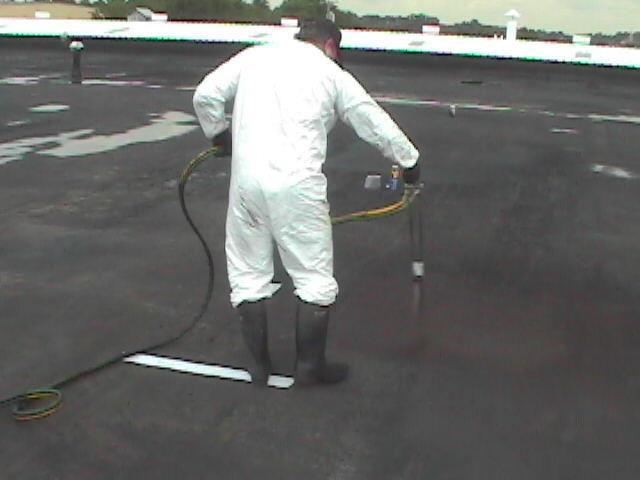
23 APPLICATION Determine whether the Liquid Rubber Membrane is required as a coating, or a membrane. The recommended minimum thickness for a coating is 1 mm. The minimum recommended application of a membrane is 2 mm. In either case the application procedures below are the same. Begin spraying from the lowest point of the roof to the highest point. Spray a thickening of material (twice the system thickness) to all vertical to horizontal intersections, such as wall/roof turn-ups, and to all expansion and construction joints, fillets and details. This thickening should extend 100 mm up the vertical surface and 150 mm onto the horizontal and at corners.
24 Detail Liquid Rubber Membrane around all penetrations. Check Liquid Rubber Membrane for correct thickness in a grid pattern that incorporates sections not greater than 50 m2. If desired, application of a coating may proceed following a minimum of five (5) days curing. In this case, the membrane must be washed down with water to remove residue.
25 OVER WOOD DECKING The following is a typical specification for the Liquid Rubber Membrane when applied as a coating or new membrane directly over wooden roof decks. Each project will have special conditions and these should be identified and addressed additional to this specification. If in doubt, seek the advice of Liquid Rubber Industries Inc. before proceeding. QUALITY ASSURANCE The Liquid Rubber Membrane may only be applied by a qualified licensed Liquid Rubber Industries Inc. Applicator. A pre-installation conference, to include at least the contractor, Applicator and architect/engineer should be held prior to application to ensure proper substrate and conditions.
26 INSPECTION Prior to commencement of work, a thorough inspection of the deck surface should be carried out to determine or confirm the following: A satisfactory surface for application. Positive and functioning drainage to deck surfaces. Soundness and correctness of detailing to pipe penetrations, flashing, outlets, turn-ups, etc. The presence of dry rot or delaminating in the deck or supports as a result of existing leaks. Such areas should be clearly marked. The presence of large irregularities (i.e.: knot holes etc.) or large gaps or open areas in the decking. Such areas should be clearly marked. The soundness of the paint, if the existing decking has been painted, and the compatibility of the paint and the Liquid Rubber Membrane. If in doubt, compatibility should be determined by spraying a small test area.
27 PREPARATION The Liquid Rubber Membrane must be installed on a clean, dry and structurally sound surface, free of sharp edges, loose or foreign material, dirt, oil, grease or other materials or debris that may damage the Liquid Rubber Membrane. Repair and/or replace any details, flashing, penetrations or panels found to be suspect. Overlap details onto the existing roofing system three (3) times the diameter of pipe penetrations or a minimum of 100 mm to all sides.
28 Clean all newly installed metal surfaces, including details, flashings, penetrations and panels, with environmentally friendly cleaner, to remove any residual factory oils, rust or scale. Clean all other bare metal surfaces to which Liquid Rubber Membrane will be applied and etch with environmentally friendly cleaner. Water wash to complete the cleaning process. Power wash in the case of heavy rust or scale. Heavy rust or scale may require more than one application. All metal surfaces treated with environmentally friendly cleaner solution should be coated with Liquid Rubber Membrane promptly to avoid flash rusting.
29 Power wash or otherwise clean all other areas of the deck, as necessary, to provide a dirt free surface for application. If the existing deck has been coated, remove all loose and flaking material. In some cases, coated surfaces should be etched with environmentally friendly cleaner or primed to ensure proper adhesion of Liquid Rubber Membrane. If in doubt, consult Liquid Rubber Industries Inc. prior to application. Apply a fillet, as necessary, after allowing time for surfaces to dry. Install 20 mm x 20 mm fillets to all 90- degree turn-ups, including details and penetrations, using a 100 mm knife to provide slightly curved fillets, leaving a smooth surface and transition.
30 Fill all large irregularities or depressions with suitable filler. Fill all joints to prevent entry of water into the interior during the curing process. Allow 12 hours cure time prior to application of the Liquid Rubber Membrane over filleting material. Mask all areas as needed for protection from over-spray. Mask terminations to a straight line.
31 APPLICATION Determine whether the Liquid Rubber Membrane is required as a coating, or a membrane. The minimum recommended thickness for a coating in 1 mm. The minimum recommended thickness for a membrane is 2 mm. In either case the application procedures below are the same. Begin spraying from the lowest point of the deck to the highest point. Spray a thickening of material (twice the system thickness) to all vertical to horizontal intersections, such as wall/roof turn-ups, and to all expansion and construction joints, fillets and details. This thickening should extend 100 mm up vertical surface and 150 mm onto the horizontal and corners.
32 Detail Liquid Rubber Membrane around all penetrations. Check Liquid Rubber Membrane for correct thickness in a grid pattern that incorporates section of not greater than 10 m2. Application of a coating, if desired, can proceed following a minimum of five (5) days curing. In this case wash Liquid Rubber Membrane with water to remove residue.
33 OVER MODIFIED BITUMEN ROOFING GENERAL The following is a typical specification for the Liquid Rubber Membrane when applied as a coating or new membrane over smooth hot pour or modified bitumen membrane systems. Each project will have special conditions and these should be identified and addressed additional to this specification. If in doubt, seek the advice of Liquid Rubber Industries Inc. before proceeding. QUALITY ASSURANCE The Liquid Rubber Membrane may only be applied by a qualified licensed Liquid Rubber Industries Inc. Applicator. A pre-installation conference, to include at least the contractor, Applicator and architect/engineer should be held prior to application to ensure proper substrate and conditions.
34 INSPECTION Prior to commencement of work, a thorough inspection of the roof surface should be carried out to determine or confirm the following. A positive slope to, and functioning of, the roof drainage system. The soundness of the existing roof membrane to the roof. The presence of wet insulation or dry rot resulting from existing leaks, using a moisture meter and taking core samples, where indicated. The soundness and proper detailing of roof mounted supports, penetrations, flashings, outlets, turn-ups, sumps and all other items which are to be part of the new, completed roofing system. The presence of delaminated layers of existing roof felts or sheeting, such as sheet laps, or large blisters, fish mouths or cracked or brittle areas. All such areas should be clearly marked. The soundness and correctness of the existing top coat, if the membrane has been coated, to the existing membrane, and the compatibility of the coating and the Liquid Rubber Membrane. If in doubt, compatibility should be determined by spraying a small test area.
35 PREPARATION The Liquid Rubber Membrane must be installed on a clean, dry and structurally sound surface, free of sharp edges, loose or foreign material, dirt, oil, grease or other materials or debris that may damage the Liquid Rubber Membrane. If existing roof is granulated modified, remove granules to fullest extent possible by using power broom or other suitable means. Remove all grates, drain covers, and other fittings and loose items on the roof surface. Repair dry rot and replace wet insulation, as needed. New insulation should be sufficient thickness so as to be level with existing roof. Fill any significant cracks or voids in the immediate substrate with suitable filler, using a backer rod, where necessary, and trowel to form a smooth surface. If the existing roof has been coated and the coating found compatible with the Liquid Rubber Membrane, remove all loose and flaking material.
36 Cut out all large blisters and delaminated areas and patch with suitable filler as follows: Cut a "Y" through the blister or delaminated area and fold the segments back to a sound roof. Thoroughly dry any moisture from the exposed area and remove any dirt or debris. Apply suitable adhesive to the exposed area, fold the segments back over the adhesive and trowel smooth. Top-dress the repair with suitable filler and trowel smooth over an area 200 mm outward from the outside edges of the repair. Once the existing roof has been determined to be a sound substrate for application, repair and/or replace any details, flashings or penetrations found to be suspect. Overlap details onto existing membrane three (3) times the diameter of pipe penetrations or a minimum of 100 mm to all sides.
37 Clean all newly installed metal surfaces, including details, flashings, penetrations and panels, environmentally friendly cleaner, to remove any residual factory oils, rust or scale. Clean all other bare metal surfaces to which will be applied and etch with (No muratic acid) water wash to complete the cleaning process. Power wash in the case of heavy rust or scale. Heavy rust or scale may require more than one application. All metal surfaces treated with environmentally friendly cleaner solution should be coated with Liquid Rubber Membrane promptly to avoid flash rusting. Power wash or otherwise clean all other areas of the roof, as necessary, to provide a dirt-free surface for application. If the existing roof has been coated, remove all loose and flaking material. In some cases, coated surfaces should be etched with environmentally friendly cleaner or primed to ensure proper adhesion of Liquid Rubber Membrane if in doubt, consult Liquid Rubber Industries Inc. prior to application of Liquid Rubber Membrane.
38 Apply a fillet, as necessary, after allowing time for surfaces to dry. Install 20 mm x 20 mm fillets to all 90-degree turn-ups, including details and penetrations, using a 100 mm knife to provide slightly curved fillets, leaving a smooth surface and transition. Fill all large irregularities or depressions with suitable filler. Fill all joints to prevent entry of water into the interior during the curing process. Allow 12 hours cure time prior to application of the Liquid Rubber Membrane over filleting material. Mask all areas as needed for protection from over-spray. Mask terminations to a straight line.
39 APPLICATION Determine whether the Liquid Rubber Membrane is required as a coating, or a membrane. If a coating, the recommended minimum thickness is 1 mm. The minimum recommended thickness of a membrane is 2 mm. In either case the application procedures below are the same. Begin spraying from the lowest point of the roof to the highest point. Spray a thickening of material (twice the system thickness) to all vertical to horizontal intersections, such as wall/roof turn-ups, and to all construction and expansion joints, fillets and details. This thickening should extend 100 mm up the vertical surface and 100 mm onto the horizontal and at the corners. In all cases, continue the Liquid Rubber Membrane beyond existing, underlying membrane and any underlying filling.
40 Detail Liquid Rubber Membrane into sumps and penetrations, whether or not the existing underlying membrane is detailed into these areas. Check Liquid Rubber Membrane for correct m2 thickness in a grid pattern that incorporates sections not greater than 50. Application of a coating, if desired, can proceed following a minimum of five (5) days curing.
41 ROOF WATERPROOFING AND COATING SPECIFICATIONS Applicator must provide fluid applied roofing as indicated, specified and required By Liquid Rubber Industries Inc. Principle work in this Section includes: Cold fluid applied roof coatings on buildings Related work not in this Section: Flashing and sheet metal Joint sealers Note: General Requirements applies to this Section
42 QUALITY ASSURANCE Roofing Contractor/Applicator shall be trained and approved by manufacturer, Liquid Rubber Industries Inc. A pre-installation conference shall be held prior to application of roofing membrane to assure proper substrate and installation conditions, to include contractor, Applicator, architect (engineer and special inspector (if any)). SUBMITTALS Project Data Submit manufacturers' product data and installation instructions for specific applications. Sample - Submit representative samples of the following for approval: Roofing membrane material Base Sheet Scrim Top coats Foot traffic pads
43 DELIVERY, STORAGE AND HANDLING Deliver materials to site in original unbroken packages bearing manufacturer's label showing; brand, weight, volume and batch number. Store materials at site in strict compliance with manufacturer's instructions. Do not allow materials to freeze in containers. JOB CONDITIONS Protect and mask all adjacent areas from overspray. Perform work only when existing and forecasted weather conditions are within manufacturers recommendations for the material and product used.
44 Minimum clearance of 24 inches is required for the application of product. For areas with less than 24-inch clearance, the product may be applied by hand using Liquid Rubber Trowel Grade. Ambient temperature shall be within manufacturers specifications (greater than 45 Deg F/7 Degree C). All plumbing, electrical, mechanical and structural items to be under or passing through the roofing membrane shall be positively secured in their proper positions and appropriately protected prior to membrane application.
45 MATERIALS PRODUCTS Liquid Rubber Membrane is a fluid applied roofing system. Waterborne and spray to be applied at ambient temperatures. A nominal thickness of 80 dry mils (60 mil minimum) unless specified otherwise. Liquid Rubber Membrane is non-toxic and odorless.
46 EXECUTION EXAMINATION All surfaces to be roofed shall be inspected and approved by the Applicator at least one day prior to commencing work. SURFACE PREPARTION Provide 24-inch minimum clearance out from surfaces to receive the roofing membrane. The application surface shall be prepared for the Applicator in accordance with manufacturer's specifications listed below: Concrete Roof Decks Concrete surfaces shall be light broom finish or smooth free of any dirt, debris, and loose material, release agents or curing compounds. Fill all voids more than ¼ inch deep and ¼ inch wide. All penetrations shall be prepared in accordance with manufacturers specifications. Prepare all flashings in accordance to common roofing practice.
47 Wood Roof Decks Wood surfaces shall he clean and free of dust. Plywood decking shall be ½ inch / 5-ply minimum. All plywood edges shall have solid blocking. Wood sheathing and framing must be inspected carefully for any signs of dry rot. Replace all dry-rotted wood. Prepare all flashings in accordance to common roofing practice.
48 Existing Built-up Roofing Expose a smooth application surface by removing all gravel, debris, dirt and loose material from the roof down to the existing cap sheet. Air-blast or vacuum the entire roof just prior to application. If the original roof has gravel imbedded into a tar coat, the existing roof shall be spud, scratched and vacuumed to create a smooth, clean surface. In either case, areas of previous ponding or leaking shall be cored and checked for dry rot. Replace all dry-rotted wood. Prepare all flashings in accordance to common roofing practice.
49 Metal Roofs New metal shall be treated to remove any residual factory oils from the surface. Air-blast or vacuum the entire roof just prior to application. Tighten all fasteners as required. All panel joints shall be prepared by precoating with Liquid Rubber Trowel Grade (spray or troweled) as required by inspections.
50 Miscellaneous Metals Exposed steel straps or other steel elements, which are to be sealed beneath the membrane, shall be clean and free of loose scale. Each steel element shall then be 3-coarsed with the following layers before application of the Liquid Rubber Roofing Membrane: 80 mils Liquid Rubber Trowel Grade, fiberglass scrim, followed by 80 mils Liquid Rubber Trowel Grade. This preparation shall extend a minimum of 6 inches beyond the steel. New metal shall be treated to remove any residual factory oils from the surface.
51 INSTALLATION As Liquid Rubber Membrane is a modified emulsion, some water will be ejected as part of the curing process. All cracks or holes should be patched prior to applying Liquid Rubber Membrane. During the curing process, any ponding water must be removed to allow the membrane to properly cure. Once fully cured, the Liquid Rubber Membrane will support ponding water.
52 INSTALLATION ON CONCRETE Due to the numerous variables affecting concrete (i.e.: water content, mix specifications, cement source, "free-line" percentage, calcium content, pumped vs. poured, environmental conditions at the time of concrete placement, admixtures, acidity, type of finish, curing conditions, etc.) Every job will require pre-testing of Liquid Rubber Membrane to determine the installation procedure.
53 Follow the procedures below carefully. Refer to Section "Sealing Around Penetrations", for procedures to seal around penetrations. Provide a ¾ inch minimum cant of Liquid Rubber Trowel Grade, or other suitable material, at all horizontal to vertical transitions and other inside corners of 90-degree or less. Leave to cure a minimum of 24 hours before the application of Liquid Rubber Membrane.
54 Delineate a test area on site with a minimum dimension of 10 feet by 10 feet (3m by 3m). Apply Liquid Rubber Membrane to a thickness of 80 mills and let it cure for 24 hours. Observe for blisters. If minor or no blistering occurs, proceed to the next step. If blistering does occur, apply a thin (10-mil) tack coat of Liquid Rubber Membrane without catalyst to the concrete surface and allow to cure before proceeding (see information regarding blister repair below). Remove all standing water before application of Liquid Rubber Membrane.
55 Spray apply Liquid Rubber Membrane at 80 mil nominal dry thickness (60 mils minimum). If a second coat is required, remove any standing water from the membrane before proceeding with the second application. In all area of where recurrent traffic is expected (i.e.: equipment maintenance paths), install foot traffic pads.
56 NON-HORIZONTAL SURFACES Spray on roofs and vertical surfaces, such as parapet walls, should begin at the low point (typically at the drains) and work towards the high point. This method allows the product to adhere to the surface before hitting catalyst run-off. Note: It is normal for some blistering to occur. A small number of blister heads should be sampled and checked for proper membrane thickness. If the samples have the required membrane thickness (80 mils nominal/60 mils minimum), then the remaining blisters should not be punctured or cut. If the samples have less than the minimum 60 mils, then the area can either be re-sprayed to obtain the proper thickness, or the blisters can be cut out and the area re-sprayed or patched with Liquid Rubber Trowel Grade, to a minimum thickness of 80 dry mils over the cut-out area extending a minimum of three inches (3") beyond the cut.
57 LIGHT WEIGHT CONCRETE ROOF DECKS Refer to Section , "Sealing Around Penetrations" for procedures to seal around penetrations. Mechanically attach 28 lb fiberglass base sheet to deck in accordance with local code. Provide ¾ inch minimum cant of Liquid Rubber Trowel Grade, at all horizontal to vertical transitions and other inside corners of 90-degree or less. Allow to cure a minimum of 24 hours before the application of Liquid Rubber Membrane. Fiberglass scrim may be used over the deck area if require. As the spray application begins, set the roll ends by spraying through the scrim. Then roll out the scrim ahead of the sprayer, keeping the scrim tight and wrinkle-free at all times. Overlap seams a minimum of three (3) inches. Cut all folds or wrinkles and lay flat so as not to create voids. Attach scrim tight in all corners so as not to create voids.
58 Remove all standing water before application of Liquid Rubber Membrane. Spray-apply Liquid Rubber Membrane to an 80- mil nominal dry thickness(60 mils minimum) if a second coat is required, remove any standing water from the membrane before proceeding with the second application. In all areas of where recurrent traffic is expected (i.e.: Equipment maintenance paths), install foot traffic pads
59 NON-HORIZONTAL SURFACES Spray on roofs and vertical surfaces, such as parapet walls, should begin at the low point (typically at the drains) and work towards the high point. This method allows the product to adhere to the surface before hitting catalyst runoff.
60 WOOD ROOF DECKS Mechanically attach 28-lb fiberglass base sheet to deck in accordance with local code. Provide ¾ inch minimum cant of Liquid Rubber Trowel Grade at all horizontal to vertical transitions and other inside corners of 90-degree or less. Allow to cure a minimum of 24 hours before the application of Liquid Rubber Membrane. Roll out fiberglass scrim over entire deck without folds or wrinkles and staple at twelve (12) inches on center. Overlap seams a minimum of three (3) inches. Cut all folds or wrinkles and lay flat so as not to create voids. Attach scrim tight in all corners so as not to create voids.
61 Remove all standing water before application of Liquid Rubber Membrane. Spray-apply Liquid Rubber Membrane to an 80-mil nominal dry thickness (60 mils (minimum)). If a second coat is required, remove any standing water from the membrane before proceeding with the second application. In all area of where recurring traffic is expected (i.e.: Equipment maintenance paths), install foot traffic pads.
62 NON-HORIZONTAL SURFACES Spray on roofs and vertical surfaces such as parapet walls, should begin at the low point (typically at the drains) and work towards the high point. This method allows the product to adhere to the surface before hitting catalyst run-off.
63 OVER EXISTING BUILT-UP ROOFING Refer to Section , "Scaling Around Penetrations", for procedures to seal around penetrations. On loose gravel roofs, spud, scratch and vacuum the surface. If the surface has been spud below the level of the existing cap sheet, mechanically attach 28 lb fiberglass base sheet to deck in accordance with local code. Air-blast or vacuum the entire roof just prior to application. On existing smooth cap sheet roofs, remove all gravel and loose material. Air-blast or vacuum the entire roof just prior to application. Provide ¾ inch minimum cant of Liquid Rubber Trowel Grade at all horizontal to vertical transitions and other inside corners of 90-degree or less. Allow to cure a minimum of 24 hours before the application of Liquid Rubber Membrane.
64 Roll out fiberglass scrim over entire deck area without folds or wrinkles and staple at twelve (12) inches on center. Overlap seams a minimum of three (3) inches. Cut all folds or wrinkles and lay flat so as not to create voids. Attach scrim tight in all corners so as not to create voids. Remove all standing water before application of Liquid Rubber Membrane. Spray-apply Liquid Rubber Membrane to an 80-mil nominal dry thickness (60 mils (minimum). If a second coat is required, remove any standing water from the membrane before proceeding with the second application. In all area of where recurrent traffic is expected (i.e.: equipment maintenance paths), install foot traffic pads.
65 NON-HORIZONTAL SURFACES Spray on roof and vertical surfaces, such as parapet walls, should begin at the low point (typically at the drains) and work towards the high point. This method allows the product to adhere to the surface before hitting catalyst runoff.
66 METAL ROOFS Refer to Section "Seating Around Penetrations", for procedures to seal around penetrations. Provide ¾ inch minimum cant of Liquid Rubber Trowel Grade at all horizontal to vertical transitions and other inside corners of 90-degree or less. Allow to cure a minimum of 24 hours before the application of Liquid Rubber Membrane. Remove all standing water before application of Liquid Rubber Membrane. Spray-apply Liquid Rubber Membrane to an 80-mil nominal thickness (60 mils minimum). If a second coat is required, remove any standing water from the membrane before proceeding with the second application.
67 NON-HORIZONTAL SURFACES Spray on roofs and vertical surfaces, such as parapet walls, should begin at the low point (typically at the drains) and work towards the high point. This method allows the product to adhere to the surface before hitting catalyst run-off.
68 SEALING AROUND PENETRATIONS Clean and brush all penetrations. Roll out and nail base sheet and scrim as required above. Base sheet and scrim should be flat around the base of the penetration. Cut base sheet and scrim as tight to the penetrations as possible. Apply (80-mil nominal dry thickness 60-mil minimum) Liquid Rubber Trowel Grade in a six (6) inch wide ring around the penetration and up the penetration a minimum of six (6) inches.
69 Allow the Liquid Rubber Trowel Grade to cure completely before proceeding to the following step. Spray-apply Liquid Rubber Membrane to an 80- mil nominal dry thickness(60-mil minimum) around the penetration, completely encapsulating the collar assembly and to a height two (2) inches minimum above the trowel grade collar. Spray-apply Liquid Rubber Membrane to surrounding areas as specified for the particular application.
70 FIELD QUALITY CONTROL Field Quality Control is a very important part of all membrane applications. Applicators should check their own work for coverage, thickness, and all around good workmanship before calling for inspections. When thickness or integrity is in question, the membrane should be tested in the proper manner as described below. However, over-sampling defeats the intent of inspections. Inspectors should always use visual and tactile measurement to guide them. Areas suspected of being too thin to the touch should be measured with the gauges to determine the exact thickness. With practice and by comparing tactile measurements with those of the gauges, fingers become very accurate tools
71 INSPECTION METHOD #1 Membrane may be checked for coverage with a lightly oiled, needle nose depth gauge, or by taking four (4) cut-outs of one (1) square inch every five thousand (5,000) square feet. Record the minimum reading. Mark the test area. Test areas are to be patch over with Liquid Rubber Membrane to an 80-mil minimum dry thickness, extending a minimum of one (1) inch beyond the test perimeter.
72 INSPECTION METHOD #2 Samples to be inspected may be cut from the membrane to a minimum area of two (2) square inches per five hundred (500) square feet. Voids left by sampling are to be patched with fiberglass and must overlap the void by a minimum of two (2) inches. Spray or trowel-apply Liquid Rubber Membrane to an 80-mil minimum dry thickness, extending at least three (3) inches beyond scrim patch. Note: Due to the nature of concrete as a substrate it is normal for some blistering to occur. This is caused by either the concrete's tendency to off-gas when sealed, or water that is temporarily trapped between the concrete and the membrane. With time blisters will absorb into the concrete without detriment to the membrane.
73 A small number of blister heads should be sampled and checked for proper membrane thickness. If the samples have the required membrane thickness(80-mil nominal/60-mil minimum), then the remaining blisters should not be punctured or cut. If the samples have less than the minimum 60- mils, then the area can either be re-sprayed to obtain the proper thickness, or the blisters can be cut out and the area re-sprayed or patched with Liquid Rubber Trowel Grade.
74 TYPICAL LIQUID RUBBER MEMBRANE APPLICATION NOTES APPLICATION TECHNIQUE The Membrane shall be spray applied in liquid form and air cured to form a seamless film. The application shall be via a plural component spray gun and delivery equipment as approved by Liquid Rubber Industries. The Membrane System shall be supplied and installed by an approved Applicator. The spray gun and associated delivery equipment shall be set up such so that the separate emulsion and catalyst are combined in two even fan patterns with no precipitation of either component. It shall produce a non-liquid coating exhibiting a finely textured surface with the characteristic of uniformly releasing the water carrier contained within the emulsion. The Applicator shall avoid overbuilding the Membrane beyond 5 mm without interlaying a layer of reinforcement fabric.
75 CURING The nominal standard curing time is 48 hrs at 20oC. PROTECTION OF WORKS The works shall be barricaded to prevent pedestrian or vehicular traffic. The membrane Applicators shall attend and control their work until wear protection overlays are installed complete. REINFORCEMENT / PROTECTION Immediately upon completion of the membrane application, a covering layer of geo-textile reinforcement shall be laid level to promote adhesion to the membrane and be followed by such protective sheeting, over cladding, or coating as specified.
76 Insulation (if required): Cover all membrane surfaces both horizontally and vertically with high density polystyrene foam panels, 10 mm gap fitted to cover the entire roof membrane and aligned to facilitate roof drainage. REPAIRS If the membrane suffers damage it shall be repaired by repeating the application process and overlapping the damaged area that has been trimmed and cleaned. GENERAL NOTES The Works Contractor shall provide works access, and site safety practices to avoid endangering the waterproofing Applicator, the passing public, and the building tenants.

77 The End
Colphene BSW Training and Application Guide. Colphene BSW Waterproofing Membrane. 1. Prepare substrate
 Colphene BSW Training and Application Guide Colphene BSW Waterproofing Membrane. 1. Prepare substrate Substrate must be structurally sound. Surface must be free of voids, spalled areas, loose aggregate,
A. Submit product data sheets and literature verifying physical properties of materials.
 I. GENERAL ACRYSHIELD ROOF MANAGEMENT SYSTEM Installation Guide Specification For Preserving EPDM Roofs 07500 Saving Money, Safeguarding the Environment One Roof at a Time. 1.01 SUMMARY A. Provide labor,
LIQUID RUBBER INDUSTRIES ENGINEERING SPECIFICATIONS FOR ENGINEERS AND ARCHITECTS. Diagram 1: Standard Membrane Continuation 150 mm Overlap
 LIQUID RUBBER INDUSTRIES ENGINEERING SPECIFICATIONS FOR ENGINEERS AND ARCHITECTS Diagram 1: Standard Membrane Continuation 150 mm Overlap Ensure Membrane to Membrane Contact Diagram 2: Membrane Continuation
ITEM 458 WATERPROOFING FOR STRUCTURES
 ITEM 458 WATERPROOFING FOR STRUCTURES 458.1. Description. This Item shall govern for the furnishing and placing of waterproofing on concrete and steel bridge decks of railroad structures and on other structures
SECTION 07530CP EPDM MEMBRANE ROOFING
 PART 1 GENERAL 1.1 SUMMARY SECTION 07530CP EPDM MEMBRANE ROOFING A. Section includes: 1. Adhered membrane roofing and flashing 2. Mechanically fastened roof insulation 3. Walkway pads 1.2 ARCHITECTURAL
SECTION mil thickness COLD FLUID-APPLIED WATERPROOFING
 SECTION 07 14 16 CCW-MIRASEAL @ 120 mil thickness COLD FLUID-APPLIED WATERPROOFING PART 1 - GENERAL 1.1 SECTION INCLUDES: Installation of waterproofing membrane on surfaces indicated on drawings, consisting
DESIGN GUIDELINE FLUID-APPLIED WATERPROOFING
 DESIGN GUIDELINE FLUID-APPLIED WATERPROOFING (TO RESTORE EPDM MEMBRANES) PART 1 GENERAL 1.01 DESCRIPTION A. The scope of this design guideline is to describe the installation of the ALDOCOAT Silicone reflective
SECTION COLD APPLIED RUBBER MODIFIED ASPHALT WATERPROOFING
 P.O. Box 599 - Mars, PA 16046 800-321-3337 SECTION 07555 COLD APPLIED RUBBER MODIFIED ASPHALT WATERPROOFING PART 1 - GENERAL 1.1 RELATED DOCUMENTS A. Drawings and general provisions of the Contract, including
SECTION THERMOPLASTIC POLYOLEFIN (TPO) ROOFING PART 1 - GENERAL 1.1 RELATED DOCUMENTS
 ROOFING PART 1 - GENERAL 1.1 RELATED DOCUMENTS") SECTION 075423 - THERMOPLASTIC POLYOLEFIN (TPO) ROOFING PART 1 - GENERAL 1.1 RELATED DOCUMENTS A. Drawings and general provisions of the Contract, including Division 00 Bidding Requirements and other Division
SECTION 075423 - THERMOPLASTIC POLYOLEFIN (TPO) ROOFING PART 1 - GENERAL 1.1 RELATED DOCUMENTS A. Drawings and general provisions of the Contract, including Division 00 Bidding Requirements and other Division
SECTION MODIFIED BITUMINOUS SHEET WATERPROOFING
 SECTION 07 13 52 MODIFIED BITUMINOUS SHEET WATERPROOFING SPEC WRITER NOTE: Delete text between // // not applicable to project. Edit remaining text to suit project. PART 1 - GENERAL 1.1 SUMMARY A. Section
DURA 500 THERMOPLASTIC FLAT ROOF COATING SYSTEM BY SUPERIOR POLYMERS INC.
 SPECIFICATION GUIDELINE FOR SMOOTH ROOF SUBSTRATES INCLUDING MODIFIED BITUMEN, SMOOTH ASPHALT, EPDM, TPO, AND PLYWOOD. Part 1 General Information For the purpose of clarification in this document, the
TOPCOAT Restoration Specifications Fiberglass & MB Granulated Cap Sheets
 TOPCOAT Restoration Specifications Fiberglass & MB Granulated Cap Sheets Updated: 1/11 Quality You Can Trust From North America s Largest Roofing Manufacturer! www.gaf.com TOPCOAT Restoration Specifications
FLUID APPLIED WATERPROOFING
 SECTION 07120 FLUID APPLIED WATERPROOFING PART 1 GENERAL 1.01 SUMMARY A. Related Sections: 1. 03300 - Cast-In-Place Concrete. 2. 09200 - Metal Studs, Metal Lath, Suspension Ceilings, Plaster, and Stucco.
MANUFACTURER S (SHORT FORM) SPECIFICATION / SECTION
 SPECIFICATION / SECTION") STUC-O-FLEX - ELASTOMERIC ACRYLIC FINISH APPLICATION TO PORTLAND CEMENT PLASTER / CONCRETE RENDER MANUFACTURER S (SHORT FORM) SPECIFICATION / SECTION 09220-09 24 00 PART 1-GENERAL SCOPE: Manufacturer's
STUC-O-FLEX - ELASTOMERIC ACRYLIC FINISH APPLICATION TO PORTLAND CEMENT PLASTER / CONCRETE RENDER MANUFACTURER S (SHORT FORM) SPECIFICATION / SECTION 09220-09 24 00 PART 1-GENERAL SCOPE: Manufacturer's
SUBMITTALS Descriptive literature: Submit manufacturer's application instructions and technical data sheets or catalog cuts on materials.
 PART I GENERAL APPLICABLE PUBLICATIONS The publications listed below form a part of this specification to the extent referenced. The publications are referred to in the text by the basic designation only.
A Design Review of Waterproofing Codes
 A Design Review of Waterproofing Codes Section 1807 of Chapter 18 of the International Building Code addresses waterproofing under the section title of Dampproofing and Waterproofing. The section defines
PERM-FLEX ASSEMBLY DIRECT APPLICATION TO CEMENTITIOUS SUBSTRATES MANUFACTURERS SPECIFICATION / SECTION 09960
 STUC-O-FLEX PERM-FLEX ASSEMBLY DIRECT APPLICATION TO CEMENTITIOUS SUBSTRATES MANUFACTURERS SPECIFICATION / SECTION 09960 PART 1 - GENERAL 1.01 DESCRIPTION Provide all labor, materials and equipment necessary
CELCORE CELLULAR INSULATING CONCRETE SPECIFICATION FOR RETROFIT PLACEMENT OVER EXISTING ROOF MEMBRANES
 PART 1: SCOPE CELCORE CELLULAR INSULATING CONCRETE SPECIFICATION FOR RETROFIT PLACEMENT OVER EXISTING ROOF MEMBRANES 1.1 An Approved Celcore Applicator shall furnish all labor, materials and supervision
ARCHITECTURAL GUIDE SPECIFICATIONS - DESCRIPTIVE
 ARCHITECTURAL GUIDE SPECIFICATIONS - DESCRIPTIVE MANNINGTON COLORFIELDS SHEET RUBBER FLOORING Section 09 65 16 Sheet rubber Flooring (Thermoset Rubber) Created May 2012 Mannington Mills, Inc. P. O. Box
ROOF SUBSTRATE PREP MANUAL
 ROOF SUBSTRATE PREP MANUAL ALDOCOAT Liquid Applied Roof Restoration Systems AFTER BEFORE JULY 2016 1604 N. Main St. Kannapolis, NC 28081 (800) 474-6019 www.aldoproducts.com ROOF SUBSTRATE PREPARATION Preparation
1. Rubberized asphalt waterproofing membrane, reinforced. 2. Molded sheet drainage panels. 3. Insulation. 4. Plaza deck pavers.
 SECTION 071413 HOT FLUID APPLIED RUBBERIZED ASPHALT WATERPROOFING PART 1 GENERAL 1.1 SUMMARY A. Section Includes: 1. Rubberized asphalt waterproofing membrane, reinforced. 2. Molded sheet drainage panels.
SECTION MANUFACTURED ROOF EXPANSION JOINTS
 SECTION 07 71 29 - MANUFACTURED ROOF EXPANSION JOINTS PART 1 -GENERAL 1.1 RELATED DOCUMENTS A. Drawings and general provisions of the Contract, including General and Supplementary Conditions and Division
Louis Armstrong New Orleans International Airport NOAB Project # North Terminal Development Program Phase 1
 Louis Armstrong New Orleans International Airport NOAB Project # 8910-01233 PART 1 - GENERAL SECTION 07 71 29 - MANUFACTURED ROOF EXPANSION JOINTS 1.1 RELATED DOCUMENTS A. Drawings and general provisions
PG 9600 HIGH SOLIDS SILICONE ROOF COATING
 WARRANTY INSTALLATION GUIDE SPECIFICATION FOR RESTORATION OF EXISTING SINGLE-PLY ROOFS (20 YEAR WARRANTY) PART 1 GENERAL 1.01 SUMMARY A. PG 9600, manufactured by ProGuard Group, Inc., is a high solids,
GE SCM3500 High Solids Silicone Roof Coating
 GE SCM3500 High Solids Silicone Roof Coating Installation Guide Specification For GRANULATED or SMOOTH MODIFIED BITUMEN / BUR (20 Year Warranty) Warranty PART 1 GENERAL 1.01 SUMMARY A. This specification
Application Specification:
 Application Specification: GW-15-UBU-HD April 2014 Supersedes 5/13 PART 1 - GENERAL 1.1 SUMMARY Division 07 18 16: GACOFLEX POLYURETHANE ELASTOMERIC COATING SYSTEM FOR VEHICULAR TRAFFIC DECKS AND RAMPS
1. Decks, balconies, and sun porches 2. Walkways, ramps, and stairways 3. Patios and courtyards
 SECTION 07185 TRAFFIC MEMBRANE PART 1 GENERAL 1.1 SECTION INCLUDES A. Traffic membrane, consisting of welded seam PVC waterproofing, over f following surfaces: 1. Decks, balconies, and sun porches 2. Walkways,
May 8, 2017 ADDENDUM #1. IFB Resin Floor System For Highway Department Central District Building
 May 8, 2017 ADDENDUM #1 IFB 17-082 Resin Floor System For Highway Department Central District Building Addendum #1 is being issued to offer an alternate resin flooring system. 096700 FLUID-APPLIED FLOORING
ERSYSTEM ONESTEP PLUS
 1 DG0047-A 05/2017 AGED (EPDM, TPO, CSPE-HYPALON, PIB) SINGLE-PLY (THERMOSET) MEMBRANE RESTORATION SYSTEM APPLICATION SAMPLE DESIGN GUIDELINE ERSYSTEM ONESTEP PLUS ITW POLYMERS SEALANTS NORTH AMERICA,
Standard specification for the application of Danosa Two-Layer waterproof roofing membrane to plywood & concrete surfaces.
 Standard specification for the application of Danosa Two-Layer waterproof roofing membrane to plywood & concrete surfaces. BRANZ Appraised No. 678 Ref: P3200 Rev 1 February 2016 Page 1 of 5 1.0 PREAMBLE:
SPECIFICATION GUIDELINE
 Environmental StoneWorks specification guideline should be used to assist design professionals in the preparation of projects. Edit and delete items that may not be applicable. Verify all referenced section
Instruction Guide APPLICATION OF CIM TO CONCRETE
 23 Elm St., Peterborough, NH 03458 Tel: (800) 543-3458 (603) 924-9481 Fax: (603) 924-9482 Web site: Instruction Guide APPLICATION OF CIM TO CONCRETE 1.0 DESCRIPTION This guide covers the installation of
SECTION CAST-IN-PLACE CONCRETE
 SECTION 03300 CAST-IN-PLACE CONCRETE PART 1 GENERAL 1.01 SECTION INCLUDES A. The Contractor shall furnish all work and materials, including cement, sand and coarse aggregate, water, admixtures, curing
ROOF BALLAST MATERIALS ARCHITECTURAL CONCRETE PAVING SLABS SRS LEVELING BLOCK SYSTEM INSTALLATION PART GENERAL 1.
 07555 - ROOF BALLAST MATERIALS ARCHITECTURAL CONCRETE PAVING SLABS SRS LEVELING BLOCK SYSTEM INSTALLATION PART 1.00 - GENERAL 1.01 SUMMARY: A. The work of this section consists of furnishing and installing
SECTION EPOXY FLOORING SYSTEMS
 SECTION 09800 EPOXY FLOORING SYSTEMS PART 1 GENERAL 1.1 RELATED DOCUMENTS A. Drawings and general provisions of the Contract, including General and Supplementary Conditions and Division 1 Specification
1.2 Reference Standard: NOFMA - National Oak Flooring Manufacturers Association Grading Standards.
 WOOD FLOORING GENERAL INFORMATION 1.1 This section applies to factory finished wood strip flooring. 1.2 Reference Standard: NOFMA - National Oak Flooring Manufacturers Association Grading Standards. 1.3
SECTION RESILIENT SHEET FLOORING
 SECTION 09 65 16 RESILIENT SHEET FLOORING SPEC WRITER NOTE: Delete text between // // not applicable to project. Edit remaining text to suit project. PART 1 - GENERAL 1.1 SUMMARY A. Section Includes: 1.
FIRESTONE ULTRAPLY TPO SA APPLICATION GUIDE
 FIRESTONE ULTRAPLY TPO SA APPLICATION GUIDE I. MEMBRANE APPLICATION... 2 A. MEMBRANE... 2 II. MEMBRANE ATTACHMENT... 2 III. SEAMING... 3 A. SEAMING FOR FIRESTONE ULTRAPLY TPO SA... 3 B. T-JOINT AREAS...
Application Instructions for Dryvit Backstop NT For Use Beneath Claddings Other Than Dryvit EIFS
 Application Instructions for Dryvit Backstop NT For Use Beneath Claddings Other Than Dryvit EIFS CHECKLIST PRIOR TO THE INSTALLATION OF BACKSTOP NT - SMOOTH AND TEXTURE Project Conditions Maximum storage
J41 Reinforced bitumen membrane roof coverings
 J41 Reinforced bitumen membrane roof coverings To be read with Preliminaries/General conditions. A comprehensive waterproofing system comprising two reinforced bituminous membranes fully adhered to thermal
SECTION BRICK MASONRY ASSEMBLIES
 PART 1 - GENERAL 1.1 SUMMARY A. Section includes the following: 1. Face brick. 2. Mortar and grout. 3. Ties and anchors. 4. Miscellaneous masonry accessories. 1.2 SUBMITTALS A. Product Data: For each type
1 PVC or ABS drain with strainer
 Patents Pending ProBase II Single-Slope Shower Base and Kit CONTENTS 1. General Information...1 2. Materials...1 3. Planning...2 4. Preparation...3 5. Layout...3 6. Install Base and Shims...4 7. Install
ARDEX GUIDE SPECIFICATION ARDEX CD Concrete Dressing and ARDEX CD FINE Concrete Dressing Polymer-Modified, Portland Cement-Based, Resurfacing Compound
 ARDEX GUIDE SPECIFICATION ARDEX CD Concrete Dressing and ARDEX CD FINE Concrete Dressing Polymer-Modified, Portland Cement-Based, Resurfacing Compound SECTION 03 01 30 MAINTENANCE OF CAST-IN-PLACE CONCRETE
Pacific Polymers Elasto-Deck BT Guide Specification
 1 07141-1 August 2016 Pacific Polymers Elasto-Deck BT Guide Specification SECTION 07141 FLUID APPLIED WATERPROOFING 2 07141-2 August 2016 Pacific Polymers Elasto-Deck BT Guide Specification SECTION 07141
A. ASTM C 150 Standard Specification for Portland Cement. B. ASTM C 595 Standard Specification for Blended Hydraulic Cements.
 TECHNICAL SPECIFICATIONS SEWER MANHOLE REHABILITATION SYSTEM WITH A PROTECTIVE CEMENT LINER AND HIGH BUILD EPOXY COATING (As Provided by Standard Cement Materials) FOREWORD The following specification
FireShield System Specifications Mineral Surface Cap, Mop Granule and Torch Granule APP Cap Sheets
 FireShield System Specifications Mineral Surface Cap, Mop Granule and Torch Granule APP Cap Sheets Updated: 1/11 Quality You Can Trust From North America s Largest Roofing Manufacturer! www.gaf.com FireShield
PLATON RUGGED, DIMPLED HIGH-DENSITY POLYETHYLENE (HDPE) MEMBRANE THAT KEEPS FOUNDATIONS AND FLOORING DRY ADVANCED TECHNOLOGY EASY INSTALLATION
 MEMBRANE THAT KEEPS FOUNDATIONS AND FLOORING DRY ADVANCED TECHNOLOGY EASY INSTALLATION") DRAINAGE SOLUTIONS SINCE 1908 PLATON RUGGED, DIMPLED HIGH-DENSITY POLYETHYLENE (HDPE) MEMBRANE THAT KEEPS FOUNDATIONS AND FLOORING DRY ADVANCED TECHNOLOGY EASY INSTALLATION PROVEN PERFORMANCE ARMTEC.COM
DRAINAGE SOLUTIONS SINCE 1908 PLATON RUGGED, DIMPLED HIGH-DENSITY POLYETHYLENE (HDPE) MEMBRANE THAT KEEPS FOUNDATIONS AND FLOORING DRY ADVANCED TECHNOLOGY EASY INSTALLATION PROVEN PERFORMANCE ARMTEC.COM
AVM System 500. Aussie Membrane 500
 Generic Spec TECH DATA SHEET Sections - 071000 / 071400 / 071416 ICC ESR-2503 L.A. RR#: 25550 Heavy Duty Below Grade Bituminous Waterproofing Membrane Sections 071000 / 071400 / 071416 Fluid Applied Waterproofing
TOPCOAT Restoration Specifications Structural Concrete
 TOPCOAT Restoration Specifications Structural Concrete Updated: 1/11 Quality You Can Trust From North America s Largest Roofing Manufacturer! www.gaf.com TOPCOAT Restoration Specifications Structural Concrete
Installation Guide Wall Panels
 Installation Guide Wall Panels Jointless or Dry-Stacked Installation (Read Prior to installation) The MStone system is a jointless / dry-stacked installation where panels and corners fit tightly together
By CTS Cement Manufacturing Corp.
 CSI SECTION 03 60 00 GROUTING 03 62 00 NON-SHRINK GROUTING 03 62 13 NON-METALLIC NON-SHRINK GROUTING High Flow, Non-Metallic, Multi-Purpose, Cementitious, Non-Shrink Grout EDITOR NOTE: The following guideline
SPECIFICATION GUIDELINE
 SPECIFICATION GUIDELINE Environmental Stoneworks Corporate Office 6300 East Stapleton Drive South Denver, CO 80216 Phone (303) 309-3040 Fax (303) 309-3059 www.estoneworks.com Environmental Stoneworks specification
TEX COTE 600 TEXTURED COATING MASONRY PROTECTIVE COATING
 SECTION 09960 - TEXTURED COATINGS Coating System Submittals Guide Specification TEX COTE 600 TEXTURED COATING MASONRY PROTECTIVE COATING (SPLIT FACE OR SAND FINISH BLOCK) 1. TEX COTE 600, Textured Coating
Acry-Tek 4200 / SPF Recoat System
 WARRANTY SPECIFICATION Acry-Tek 4200 / SPF Recoat System MASTER GUIDE SPECIFICATIONS This MASTER GUIDE-SPEC is a brief outline of Coating & Foam Solutions, LLC.(CFS) roofing requirements and is intended
Guideline Specification ACRYMAX ARS-1-C Reinforced Composite Elastomeric Membrane System for Concrete Roofs Fluid-Applied Roofing
 221 Brooke Street Media, PA 19063 610-566-7470 Fax 610-891-0834 Website www.acrymax.com e-mail info@acrymax.com This document is intended to provide guidelines for the proper specification and application
RUBBERGARD EPDM SA APPLICATION GUIDE
 RUBBERGARD EPDM SA APPLICATION GUIDE I. MEMBRANE APPLICATION... 2 A. MEMBRANE... 2 II. MEMBRANE ATTACHMENT... 2 A. MEMBRANE PREPARATION... 2 B. MEMBRANE APPLICATION... 2 III. SEAMING... 3 VI. MEMBRANE
1.02 DESCRIPTION A. This Section specifies furnishing and installing Surface Applied Detectable/Tactile Warning Surface Tiles where indicated.
 SURFACE APPLIED DETECTABLE/TACTILE WARNING SURFACE TILE PART 1 GENERAL 1.01 RELATED DOCUMENTS A. Drawings and general provisions of Contract, including General and Special Conditions and Division 1 Specifications
THE BRITE THING TO DO
 REDUCING ENERGY CONSUMPTION IMPROVING AIR QUALITY THE BRITE THING TO DO BRITE-n-EZ Enhanced Coating Application Process on Black EPDM Roof Membrane BRITE-n-EZ EPDM Application Instructions CLEANING Remove
REV:6-30/09/30. Liquid Rubber Timber Specification
 REV:6-30/09/30 Liquid Rubber Contents: 1. Preparation 2. Application 3. Additional Information 4. Things To Be Aware Of When Applying To Timber 1. Preparation: Prior to commencing ensure the decking is
TOPCOAT System Specifications Corrugated Transite Panels
 TOPCOAT System Specifications Corrugated Transite Panels Updated: 1/11 Quality You Can Trust From North America s Largest Roofing Manufacturer! www.gaf.com TOPCOAT System Specifications Corrugated Transite
SCOPE OF WORK PROJECT IDENTIFICATION
 PROJECT IDENTIFICATION SCOPE OF WORK PROJECT NAME: Wickenburg High School PROJECT: Gym Roof 1 SITE ADDRESS: 1090 S. Vulture Mine Rd. Wickenburg AZ 85390 City State ZIP Code SCOPE OF WORK SUMMARY: 1. Extend
SECTION COMMON WORK RESULTS FOR CONCRETE SSPECIALTY COATINGS
 SECTION 03 05 00 COMMON WORK RESULTS FOR CONCRETE 09 97 00 SSPECIALTY COATINGS Weld Crete ************************************************************************************************************************
B. Store products in dry spaces protected from the weather, with ambient temperatures maintained between 50 and 90 deg F (10 and 32 deg C).
.") SECTION 09651 - RESILIENT TILE FLOORING PART 1 - GENERAL 1.1 RELATED DOCUMENTS A. Drawings and general provisions of the Contract, including General and Supplementary Conditions and Division 1 Specification
SECTION 09651 - RESILIENT TILE FLOORING PART 1 - GENERAL 1.1 RELATED DOCUMENTS A. Drawings and general provisions of the Contract, including General and Supplementary Conditions and Division 1 Specification
***************************************************************************************************************
 09330 QUARRY TILE *************************************************************************************************************** SPECIFIER: CSI MasterFormat 2004 number 09 30 16 ***************************************************************************************************************
LEGACY REPORT DIVISION: THERMAL AND MOISTURE PROTECTION SECTION: FLUID APPLIED ROOFING REPORT HOLDER: METACRYLICS
 0 Most Widely Accepted and Trusted ICC ES Legacy Report ICC ES 000 (800) 6587 (56) 699 05 www.icc es.org ER 785 Reissued 09/017 This report is subject to renewal 09/0. DIVISION: 07 00 00THERMAL AND MOISTURE
TUFF-TAC TM BRIDGE MEMBRANE INSTALLATION GUIDE
 5 pages TUFF-TAC TM BRIDGE MEMBRANE INSTALLATION GUIDE The following will describe the proper procedure to use when installing Tuff-Tac TM bridge deck membrane. The guide will cover recommended tools to
1. Division 09 Section "Rough Carpentry."
 GREENSPOINT AND LAUDER RD. EC/PRE-KlK PAGE 1 SECTION 096400 - WOOD FLOORING PART 1 - GENERAL 1.1 RELATED DOCUMENTS A. Drawings and general provisions of the Contract, including General and Supplementary
Section COATING RESTORATION
 Sto Corp. 3800 Camp Creek Parkway Building 1400, Suite 120 Atlanta, GA 30331 Tel: 404-346-3666 Toll Free: 1-800-221-2397 Fax: 404-346-3119 www.stocorp.com 80658R StoColor Texture - Coarse Textured Acrylic-Based,
SECTION ROOF SPECIALTIES
 PART 1 - GENERAL 1.1 DESCRIPTION SECTION 07 71 00 1. Use this section only for NCA projects. 2. Delete between // // if not applicable to project. Also delete any other item or paragraph not applicable
CSI SECTION MAINTENANCE OF CONCRETE Repair & Resurfacing with Rapid Hardening, High Strength, Low-Shrink, Non-Metallic Cementitious Materials
 CSI SECTION 03 01 00 MAINTENANCE OF CONCRETE Repair & Resurfacing with Rapid Hardening, High Strength, Low-Shrink, Non-Metallic Cementitious Materials EDITOR NOTE: The following guideline specification
SECTION Pedestrian Traffic Coatings{PRIVATE } 1.1 SUMMARY (Specification writer shall add, delete or amend, as deemed necessary)
") Guide Specification MiraFlex II For Plywood Decks Pedestrian Deck and Waterproofing System (Specification writer shall choose the most appropriate section that applies to a given scope of work, including
Guide Specification MiraFlex II For Plywood Decks Pedestrian Deck and Waterproofing System (Specification writer shall choose the most appropriate section that applies to a given scope of work, including
A. Product Data: Submit manufacturer s product data, with complete general and specific installation instructions, recommendations, and limitations.
 SECTION 071700 - BENTONITE WATERPROOFING PART 1 - GENERAL 1.1 WORK SUMMARY A. The work of this section includes, but is not limited to the furnishing and installing the following materials, per project
CIM IG 13 11/06. Instruction Guide
 23 Elm St., Peterborough, NH 03458 Tel: (800) 543-3458 (603) 924-9481 Fax: (603) 924-9482 Web site: Instruction Guide APPLICATION OF CIM 2000 TO CONCRETE 1.0 DESCRIPTION This guide covers the installation
 SPECIFICATIONS FOR AluSystems Aluminum Composite Panels Series 20 Dry Joint 1.00 GENERAL 1.01 RANGE OF WORK Section includes: Laminated panels and attachment systems for use as exterior cladding. A. Provide
OREGON ROOF CONSULTING - ROOF INSPECTION FORM
 Oregon CCB: 199121 PO Box 220190, Milwaukie, OR 97222 Washington License: OREGORC871MR OREGON ROOF CONSULTING - ROOF INSPECTION FORM General Roof Conditions: NA = Not Applicable Debris on Roof Physical
INSTALLING WATER-RESISTIVE BARRIERS & FLASHING
 INSTALLING WATER-RESISTIVE BARRIERS & FLASHING IN A TWO-LAYER STUCCO APPLICATION Fortifiber Building Systems Group provides this guide to assist installers by demonstrating a two-layer installation of
SECTION ALPHAGUARD RESTORATION 20 YEAR WARRANTY SYSTEM. f. Conditions and Division 01 Specification Sections, apply to this Section.
 SECTION 07015 ALPHAGUARD RESTORATION 20 YEAR WARRANTY SYSTEM PART I.1 GENERAL A. RELATED DOCUMENTS 1. The attached are components of this section: a. General Conditions b. Supplemental Conditions c. Statement
Desmopol Application Guide onto Ply/OSB Deck
 Board and Trim Selection and Application For new roofs or when overboarding is necessary, we recommend using an 18mm Far Eastern WBP plywood or 18mm OSB3 in line with standard roofing practice. Before
MDC MicroTex Eggshell Micro-Textured Ceramic Coating for Walls
 MicroTex Eggshell Micro-Textured Ceramic Coating for Walls Specification Guide 95: 9770 Special Wall Finishes 88: 9800 Special Coatings Part 1 General 1.01 SUMMARY A. This section specifies the furnishing
SECTION SHEET MEMBRANE WATERPROOFING AND CRACK ISOLATION
 SECTION 093000 - SHEET MEMBRANE WATERPROOFING AND CRACK ISOLATION PART 1 - GENERAL This specification includes the sheet membrane used as waterproofing, vapor retarder, and crack isolation in conjunction
E. Section Polymer Modified Cement Waterproofing. K. Section Sub drainage: Foundation perimeter drainage.
 DELTA -DRAIN Section 07 10 00 Dampproofing and Waterproofing PART 1 GENERAL 1.1 SECTION INCLUDES A. Below grade drainage sheets. B. Plaza deck and planter drainage sheets. 1.2 RELATED SECTIONS A. Section
GEOGARD LO Base Coat / GEOGARD Finish Coat
 GENERAL GUIDELINE SPECIFICATION LO Base Coat / Finish Coat WATERPROOFING SYSTEM FOR MODIFIED BITUMEN ROOFS PART 1 General 1.01 General A. This document is intended to provide only general guidelines regarding
***********************************************************************************
 AQUAFIN-2K/M Two-Component Cement-based Acrylic-based Waterproofing GUIDE AQUAFIN, Inc. SPECIFICATION PART 1 - GENERAL 1.1 SECTION INCLUDES SECTION 07 16 14 ACRYLIC MODIFIED (FLEXIBLE) CEMENTITIOUS WATERPROOFING
TILE TILE
 09300 - TILE 09300-1 PART ONE: GENERAL 1.1 Description TILE 1.1.1 Work of this Section, as shown or specified, shall be provided by the Interior Contractor and shall be in accordance with the requirements
SIKALASTIC-152 EXTERIOR WATERPROOFING MEMBRANE. Product. Scope. Appraisal No. 811 [2013] Appraisal No. 811 (2013) Amended 28 August 2017
![SIKALASTIC-152 EXTERIOR WATERPROOFING MEMBRANE. Product. Scope. Appraisal No. 811 [2013] Appraisal No. 811 (2013) Amended 28 August 2017](/thumbs/76/73001868.jpg "SIKALASTIC-152 EXTERIOR WATERPROOFING MEMBRANE. Product. Scope. Appraisal No. 811 [2013] Appraisal No. 811 (2013) Amended 28 August 2017") SIKALASTIC-152 EXTERIOR WATERPROOFING MEMBRANE Amended 28 August 2017 BRANZ Appraisals Technical Assessments of products for building and construction. Sika (NZ) Ltd PO Box 19 192 Avondale Auckland 1746
SIKALASTIC-152 EXTERIOR WATERPROOFING MEMBRANE Amended 28 August 2017 BRANZ Appraisals Technical Assessments of products for building and construction. Sika (NZ) Ltd PO Box 19 192 Avondale Auckland 1746
General Applications Before applying, mix the pre-measured catalyst* into Liquid Roof by following label directions.
 General Applications Before applying, mix the pre-measured catalyst* into Liquid Roof by following label directions. Surface Preparation: Surface to be coated should be clean, dry and structurally sound.
.1 Provide submittals in accordance with Section Submittal Procedures.
 Place D Orléans Transitway Section 07 13 52 1231 Place D Orléans Dr, Ottawa, ON. WATERPROOFING MEMBRANE City of Ottawa Project No. CR008042 Page 1 of 2 1 GENERAL 1.01 SUBMITTALS.1 Provide submittals in
PermaroofUK. Frequently asked questions
 PermaroofUK Frequently asked questions What is Firestone RubberCover membrane? Firestone RubberCover EPDM is a 100% cured single-ply roofing membrane made of a synthetic rubber Ethylene-Propylene-Diene
SLATE ROOFING INSTALLATION PROPOSAL [Last updated 10/08/2017]
![SLATE ROOFING INSTALLATION PROPOSAL [Last updated 10/08/2017]](/thumbs/72/67816830.jpg "SLATE ROOFING INSTALLATION PROPOSAL [Last updated 10/08/2017]") [Change these specifications as needed. Use this sample proposal at your own risk. This is a simple, general proposal and is not meant to be a comprehensive proposal for all situations or projects. If
[Change these specifications as needed. Use this sample proposal at your own risk. This is a simple, general proposal and is not meant to be a comprehensive proposal for all situations or projects. If
Technical Service. INSTALLATION INSTRUCTIONS FOR TARAFLEX SPORT PRODUCTS over Gypsum base Products. This document refers to the following products:
 INSTALLATION INSTRUCTIONS FOR TARAFLEX SPORT PRODUCTS over Gypsum base Products This document refers to the following products: Product Width Width Ft. Installation direction Seams treatment Taraflex Surface
Kolorines Glass Mosaic Tiles Project Specification
 Kolorines Glass Mosaic Tiles Project Specification SUGGESTED SPECIFICATION Glass Mosaic Tile Installation for Swimming Pools NOTES TO SPECIFIER: 1. Specify PremiumPlus Thin-Set mixed with CustomFlex Additive
CS-100 Guide Specifications
 MANUFACTURER CUSTOM-BILT METALS 1333 Corporate Drive, Suite 103 Irving, Texas 75038-2520 (800) 826-7813 or info@custombiltmetals.com www.custombiltmetals.com CS-100 Guide Specifications This Guide Specification
Application Instructions for Keystone Kool Deck on Existing Concrete
 Application Instructions for Keystone Kool Deck on Existing Concrete REQUIRED MATERIALS Keystone Kool Deck PTA Bonding Agent Water 20 Mesh Marble Sand White Portland Cement OPTIONAL TOOLS Mortex Pattern
GenFlex EZ TPO Peel & Stick SA (HW) APPLICATION GUIDE
 APPLICATION GUIDE") GenFlex EZ TPO Peel & Stick SA (HW) APPLICATION GUIDE I. MEMBRANE APPLICATION... 2 A. MEMBRANE... 2 II. MEMBRANE ATTACHMENT... 2 III. SEAMING... 3 A. SEAMING FOR GENFLEX EZ TPO PEEL & STICK SA (HW)...
GenFlex EZ TPO Peel & Stick SA (HW) APPLICATION GUIDE I. MEMBRANE APPLICATION... 2 A. MEMBRANE... 2 II. MEMBRANE ATTACHMENT... 2 III. SEAMING... 3 A. SEAMING FOR GENFLEX EZ TPO PEEL & STICK SA (HW)...
GigaCrete Specification PlasterMax. PlasterMax : Fire Rated Plaster for Direct Application over Cement Masonry Units (CMU) Interior Walls
 Interior Walls") GigaCrete Inc. 6775 Speedway Blvd. Suite M105 Las Vegas, NV 89115 Ph (702) 643-6363 Fax (702) 643 1453 www.gigacrete.com GigaCrete Specification PlasterMax PlasterMax : Fire Rated Plaster for Direct Application
GigaCrete Inc. 6775 Speedway Blvd. Suite M105 Las Vegas, NV 89115 Ph (702) 643-6363 Fax (702) 643 1453 www.gigacrete.com GigaCrete Specification PlasterMax PlasterMax : Fire Rated Plaster for Direct Application
ADA APPROVED SURFACE APPLIED DETECTABLE WARNING SYSTEM
 ADA APPROVED SURFACE APPLIED DETECTABLE WARNING SYSTEM PART 1 GENERAL 1. RELATED DOCUMENTS A. Drawings and general provisions of Contract, including General and Special Conditions, apply to this Section.
GE Enduris* 3500 High Solids Silicone Roof Coating
 GE Enduris* 3500 High Solids INSTALLATION GUIDE SPECIFICATION FOR RESTORATION OF EXISTING SINGLE-PLY ROOFS (20 YEAR WARRANTY) PART 1 GENERAL 1.01 SUMMARY A. GE Enduris* 3500 silicone roof coating, manufactured
Engineering Branch Assets Delivery Group
 F.1 SCOPE This Technical Specification shall apply to Fibre Reinforced Plastics or Glass Reinforced Plastics (hereinafter referred to as FRP or GRP) structures and the materials used in their manufacture,
ROOFING CONTRACTORS GENERAL TRADE KNOWLEDGE EXAMINATION CONTENT INFORMATION
 ROOFING CONTRACTORS GENERAL TRADE KNOWLEDGE EXAMINATION CONTENT INFORMATION Revised September 14 The General Trade Knowledge portion of the examination is administered daily in Computer Based Testing (CBT)
B. Related Sections: 1. Division 07 Section "Joint Sealants" for sealing of expansion, contraction, control, and isolation joints in tile surfaces.
 SECTION 093000 - CERAMIC TILE PART 1 - GENERAL 1.1 RELATED DOCUMENTS A. Drawings and general provisions of the Contract, including General and Supplementary Conditions and Division 01 Specification Sections,