Substation Grounding Tutorial
|
|
|
- Valentine Pitts
- 6 years ago
- Views:
Transcription

1 Joe Gravelle, P.E. Eduardo Ramirez-Bettoni, P.E. Minnesota Power Systems Conference Thursday, Nov. 9, 2017

2 Presenter Joe Gravelle, P.E. Joe Gravelle earned BSEEE from NDSU in After graduation Joe worked in the mining industry in northeastern Minnesota for ten years. Joe is a principal engineer in the Substation Engineering department at Xcel Energy and has held many roles in the department since In addition to substation projects, Joe is active in standards work both at Xcel Energy and in IEEE Substations Committee. Joe is currently the vice chair of the Substations Committee and is active in leadership roles and as an active member in several IEEE working groups.

3 Presenter Eduardo Ramirez-Bettoni, P.E. Eduardo obtained a BSEE with Power System emphasis from University of Costa Rica in Eduardo has international experience in substation construction, O&M, and design in substations up to 500 kv. He has practiced engineering in the U.S., Canada and Costa Rica. Eduardo has a background in protection & control, substation physical design and power system grounding. Eduardo works as principal engineer for Xcel Energy in the Transmission & Substation Standards (TSS) department. TSS creates standard documents for design, specification and installation practices for transmission & substation facilities. Eduardo is an active member in IEEE Substation working groups.


4 Xcel Energy No. 1 utility wind energy provider in the U.S. 3.4 million electric customers 2 million natural gas customers 12,000 employees
5 Agenda 1. Grounding Basics 2. Soil Resistivity Testing and Soil Modelling 3. Design & Modelling of Substation Grid 4. Break 5. Grounding Design Variables Soil model variables Seasonal modelling of soil Crushed rock resistivity Fault current design margin Fault clearing time Summary / Combined effect


6 Grounding Basics Definitions per IEEE 80 & 81 GPR, mesh / step / touch Current split

7 Grounding Basics Touch potentials: 3 hand-to-foot Step potentials: 3 foot-to-foot Safe if Calculated Values < Tolerable Max Values

8 Grounding Basics Substation Grounding Tutorial
9 Grounding Basics Substation Grounding Tutorial
10 Grounding Basics - Example Future fault current: 7000 A Earth current: 4200 A, (split factor S f = 60%) Grid resistance: 1.07 Ω GPR nom = 1.07Ω x 4200 A = 4500 V Mesh voltage = 210 V Body current I B (500 ms, 50 kg) = 0.116/SQRT(0.5) = 164 ma

11 Grounding Basics - Example
12 Grounding Basics Body current (I B ) is based on let-go current per experimentation (99.5 % percentile, no ventricular fibrillation) Body resistance (R B ) varies based on exposure voltage R B = Ω Source: IEEE
13 Grounding Basics - Example Future fault current: 7000 A Earth current: 4200 A, (split factor S f = 60%) Grid resistance: 1.07 Ω GPR nom = 1.07 Ω x 4200 A = 4500 V Mesh voltage = 210 V Body current I B (500 ms, 50 kg) = / SQRT(0.5) = 164 ma
14 Example - Body Voltage Tolerable potential across 50 kg body, body only Percentile IB (A) RB (Ω) VB (V) Body Configuration 95% Hand-hand; Foot-foot 95% Hand-both feet 95% Both hands-both feet 95% Hand-trunk V B = I B x R B (for TPG calculations)
15 Example-Touch potential (no rock) Tolerable potential across 50 kg body, step voltage, no surface rock Homogeneous soil resistivity: 100 Ω-m Accounts for foot resistance to surface, V t, 50kg = I B x (R B +1.5ρ) Percentile IB (A) RB (Ω) Vtouch (V) Body Configuration 95% Hand-hand; Foot-foot 95% Hand-both feet 95% Both hands-both feet 95% Hand-trunk Source: IEEE
16 Example-Touch potential (with rock) Source: IEEE
17 Example-Touch potential (with rock) Tolerable potential across 50 kg body, step voltage, 4 of 2000 Ω-m surface rock; homogeneous soil resistivity: 100 Ω-m Percentile IB (A) RB (Ω) Vtouch (V) Body Configuration 95% Hand-foot 95% Hand-both feet 95% Both hands-both feet 95% Hand-trunk V t,50kg = I B x (R B +1.5xC s xρ); (Cs=0.71)
18 Grounding Basics Substation Grounding Tutorial
19 Grounding Basics Source: IEEE
20 Grounding Basics Substation Grounding Tutorial

21 Soil Analysis Substation Grounding Tutorial
22 Soil Resistivity Modelling Soil Basics Homogeneous Multi - Layered Actual soil
23 Soil Resistivity The soil is part of the fault circuit Actual circuit

24 Soil Resistivity The soil is part of the fault circuit
25 Soil Resistivity 400 Ω-m 7000 A 400 Ω-m 7000 A 1000 Ω-m 100 Ω-m 300 Ω-m 300 Ω-m 100 Ω-m 1000 Ω-m


26 Rock Resistivity 400 Ω-m 7000 A 400 Ω-m 7000 A 100 Ω-m 100 Ω-m 300 Ω-m 300 Ω-m 1000 Ω-m 1000 Ω-m
27 Preparation Soil Resistivity Testing Soil boring report Substation location & grading plans Substation size, site area Propose traverses Sources of interference Resistivity test schedule Grading schedule Test form Test equipment check list
] Water")
28 Geotechnical Exploration & Review Sand with Silt, fine grained, yellowish brown, moist medium dense (SP-SM) WEATHERED SANDSTONE, yellowish Brown, very dense, [Textural Classification: SAND WITH SILT, fine to medium grained, light brown and yellowish brown, moist, very dense (SP-SM)] Water Table
29 Soil Resistivity Testing Wenner Schlumberger Source: IEEE

30 Soil Resistivity Testing - Wenner

31 Soil Resistivity Testing - Schlumberger INSERT FORM!
32 Soil Resistivity Testing C1 P1 C2 P2 C1 P1 C2 P2
33 Error Range Based on Probe Spacing

34 Soil Resistivity Test Layout
35 Grounding Design Variables
36 Soil Resistivity Testing Summary How many traverses are required? Are there sources of interference? What is the correct layout of traverses? What pin spacing should we use? What do I do if there is not adequate space?

37 Soil Resistivity Testing Layout

38 Soil Resistivity Testing Layout

39 Soil Resistivity Testing Layout

40 Plot of Soil Resistivity Results

41 Proposed Soil Resistivity Test Traverses
42 Wenner Data Comparison Pre-& Post-Grading
43 Substation Grading Section Drawing

44 Soil Resistivity Testing Wenner vs. Schlumberger Soil Models

45 Wenner vs. Schlumberger Soil Models
46 Soil Resistivity Test Documentation Test equipment model number Test lead resistance (measured) Ambient Temperature when test was taken Date of test Standard test result form Resistivity & Resistance measurements at various pin spacing Notes

47 Soil Resistivity Modelling Soil Basics Homogeneous Multi - Layered Actual soil
48 Ground Grid Design & Modeling
49 Ground grid layout Fault current system analysis & location Split factor modeling Safety analysis V touch, V step GPR plots Substation Grounding Tutorial Design & Modeling Substation Ground Grid Safety & Summary Reports
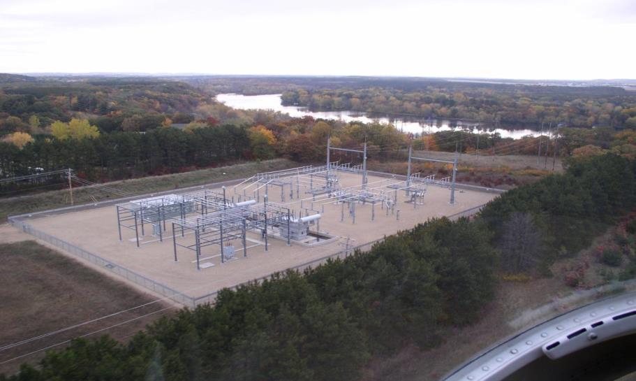
50 General Substation Layout

51 General Ground Grid Layout
52 General Ground Grid Layout 1. Grid area Loop 3 outside fence 2. Main components adjacent grid lines 3. Complete grid spacing 4. Gate(s) grading ring 5. Grading runs - UG facilities 6. Rods 7. Bond all structures & equipment

53 General Ground Grid Layout

54 General Ground Grid Layout
55 Ground Rod Application Guideline UL listed Length, diameter Spacing Perimeter Equipment Open spaces

56 Coffee Break
57 Fault Current Analysis 1. Short circuit study 1. LLG, SLG, fault duration, X/R 2. Design margin 2. Identify ground sources 1. Transformer connections 2. # of T-lines & feeders 3. Grounding transformers 4. Generator Step-Up TR connections
58 Fault Current Analysis Substation Grounding Tutorial
59 Split Factor Analysis S f = I g / (3I 0 ) TL shield wire & feeder neutral currents Grid vs. OHSW /neutral currents Hand (IEEE 80 Annex C) vs. Software calculation

60 115 kv Triple Circuit with Two Shield Wires

61 115 kv Double Circuit Line with Two Shields
62 Split Factor Analysis Substation Grounding Tutorial
63 Split Network One-Line Substation Grounding Tutorial Injected current (3I 0 ): A, 21.6 Current in shields: A, Earth current: 4911 A, 20.9 Split factor: S f = 4911/ = 86% into remote earth
64 Example 1 - Fault Analysis
65 Example 1 - Symmetrical Comp. Analysis
66 Example 2-Fault Current Analysis
67 Example 3-Fault Current Analysis F2

68 Safety Analysis - Touch Substation Grounding Tutorial
69 Safety Analysis - Step Substation Grounding Tutorial

70 Parametric Safety Analysis
71 Safety Analysis - Mitigation

72 Safety Analysis - Mitigation
73 Mitigation Options Reduce clearing time Add conductor Add rods / extend rod length Ground wells Increase area Surface rock Satellite grid Soil enhancement Bond adjacent grids
74 Leakage Current L1 L2 ρρ = 50 ρρ = 500
75 Testing Fall of Potential, IEEE Source: IEEE


76 Testing 3 Pin Method (Grid Resistance)
77 Test Lifecycle Design Maintenance
78 Grounding Study Report

79 Grounding Study Report

80 Grounding Study Report
81 Safety Analysis Report Data Soil boring report Soil resistivity test report Fault study report, current magnitude, duration, safety margin, X/R Rock, soil resistivity models Body weight IEEE 80 formulas Simulations different conditions Split Factor calculation method, assumptions Photos Drawings Protection data Substation Grounding Tutorial

")
82 Ground Grid Report Substation Grounding Tutorial Design variables Soil model data Safety analysis(touch-step potentials) Simulation files Simulation log
83 Grounding Design Variables Soil model variables (variance test results) Pre- & Post-grade Approximation method used of raw data, error, discard data Impact of fill material Limited test data
84 Grounding Design Variables

85 Grounding Design Variables
86 Substation Grading Section Drawing Rough Grade Original Surface
87 Grounding Design Variables Seasonal modelling of soils Drought, flood, winter, summer, early spring-late fall Map frost depth Multiplication factor discussion Table with various soil resistivities Mitigation options
88 Spring Conditions

89
90
91 Fall Conditions
92 Winter Conditions

93 Map Frost Depths Substation Grounding Tutorial
94 Grounding Design Variables Crushed rock resistivity Last developments - IEEE 81 Task Force Testing Examples of values Maintenance Foreign materials (wind erosion, contamination, snow, salt spray, vehicle mud & traffic, etc.)

95
96
97 Pre-grading top soil resistivity (Ω-m) Surface Rock Resistivity Examples for assumption of crushed rock value (rock not tested) Post-grading top soil resistivity (Ω-m) Use x highest soil resistivity Ω-m (if applicable)
98 I EARTH (A) No Surface Rock (283 Ω-m) Surface Rock Resistivity Touch & step potential per fault current and rock resistivity, summer, post-grade Legend: Unsafe Touch (UT), Safe Touch (ST), Unsafe Step (US), Safe Step (SS) 4 Surface Rock 300 Ω- m 4 Surface Rock 450 Ω- m 4 Surface Rock 600 Ω UT, US (1) UT, SS UT, SS UT, m ST (2900), SS 4 Surface Rock 1500 Ω-m ST (4500), 2800 UT, US (1) UT, SS UT, SS ST, SS ST, SS 2700 UT, US (1) UT, SS UT, SS ST, SS ST, SS 2600 UT, US (1) UT, SS ST, SS ST, SS ST, SS 2500 UT, US (1) UT, SS ST, SS ST, SS ST, SS 2400 UT, SS UT, SS ST, SS ST, SS ST, SS 2350 ST, SS ST, SS ST, SS ST, SS ST, SS SS
99 Fault Current Design Margin 1:1
100 Grounding Design Variables Fault clearing time Short circuit curve Explain examples of contingencies from protection perspective: BF, no BF Reclosing Functional teleprotection vs. failed, stepped distance
101 Grounding Design Variables Summary of variables & how their combined application affect design and develop consistency: Rock resistivity = 3000 Ω-m Fault current = 30 ka * 1.05 (design margin) = 31.5 ka Good soil - resistivity estimated = 100 Ω-m (uniform) 12 lines - Neutral Imp =0.19 Ω - SF= 15% flowing into grid HV lines with comms. so fault duration calculated = 10 cyc X/R low no TR in sub only HV switching station - X/R = 2.0
102 Grounding Design Variables Summary of variables & how their combined application affect design and develop consistency: Rock resistivity = surface soil resistivity layer = 355 Ω-m Fault current = 30 ka * 1.20 (design margin) = 36 ka Soil resistivity test results = 8 layer model Line model (12 lines) results Current SF = 42% flowing into grid HV lines with loss of comm. Fault duration calculated = 20 cycles (Zone 2 clearing) X/R calculated = 8.2 (round up to 10 for safety margin)

103 Conclusions & Recommendations Define acceptable ranges for design variables What assumptions are acceptable Do not focus on only one design variable Obtain accurate field data Document success and shortcomings


104 Questions? Thank You!
Substation Grounding. Presented by: Bruce Kayser, PE Assisted by Danny Seele
 Substation Grounding Presented by: Bruce Kayser, PE 785-633-5756 Assisted by Danny Seele Introduction Bruce Kayser, PE BSEE from KSU in 1989 Licensed Professional Engineer in KS Employed by ElectriComm,
Ontario ENGINEERING STANDARD SPECIFICATION 1/10 REV. ELECTRICAL DISTRIBUTION HIGH VOLTAGE SUBSTATION GROUNDING AND BONDING. Approved by.
 /0 Rev Description Revision by Approved by Issue Date YYYY/MM/DD New Format Replaces 5322-0.0. T.C. 206/02/09 T.C. 206/03/02 206/03/02 2/0.0 PURPOSE This specification describes the minimum requirements
Substation Design Volume X
 PDHonline Course E477 (4 PDH) Substation Design Volume X Grounding Instructor: Lee Layton, P.E 2015 PDH Online PDH Center 5272 Meadow Estates Drive Fairfax, VA 22030-6658 Phone & Fax: 703-988-0088 www.pdhonline.org
Soil Resistivity Data Computations; Single and Two - Layer Soil Resistivity Structure and Its Implication on Earthing Design
 Vol:7, No:, 3 Soil Resistivity Data Computations; Single and Two - Layer Soil Resistivity Structure and Its Implication on Earthing Design M. Nassereddine, J. Rizk, and G. Nasserddine International Science
Estimation of apparent soil resistivity for two-layer soil structure
 INTENATIONAL JOUNAL OF ENEGY AND ENVIONMENT Volume 4, Issue 4, 03 pp.573-580 Journal homepage: www.ijee.ieefoundation.org Estimation of apparent soil resistivity for two-layer soil structure M. Nassereddine,
Parameters Effecting Substation Grounding Grid Resistance. Dwarka Prasad 1, Dr.H.C Sharma 2
 Parameters Effecting Substation Grounding Grid Resistance Dwarka Prasad 1, Research Scholar, Uttarakhand Technical University, Dehardun (Uttarakhand), India Department of Electrical Engineering Laxmi Devi
Review of Substation Grounding Practices, Safety and Constructability Enhancements. Authors: V. SIMHA, X.WU, M.THAKUR
 Review of Substation Grounding Practices, Safety and Constructability Enhancements Authors: V. SIMHA, X.WU, M.THAKUR Agenda Grounding Study and Analysis: Substation Grounding Practices Grounding Concepts
Grounding Principles. The need to ground! Definitions. Introduction. Grounding Codes and Standards. 2 Ph:
 Introduction Grounding and bonding are an integral part of any modern electrical protection system design. An effective, low-impedance ground system is a key element of this system. It is crucial in ensuring
Improvement of Substation Earthing
 International Journal of Engineering and Advanced Technology (IJEAT) Improvement of Substation Earthing Mohammad Ali Adelian Abstract Designing a proper substation grounding system is quite complicated.
PLANNING GUIDE FOR SINGLE CUSTOMER SUBSTATIONS SERVED FROM TRANSMISSION LINES
 Prepared by: NIB/EOB PLANNING GUIDE FOR SINGLE CUSTOMER SUBSTATIONS SERVED FROM TRANSMISSION LINES 05503 Department: Electric T&D Section: T&D Engineering and Technical Support Approved by: G.O. Duru (GOD)
A Proper Design of Wind Turbine Grounding Systems under Lightning
 A Proper Design of Wind Turbine Grounding Systems under Lightning M. A. Abd-Allah, Mahmoud N. Ali, A. Said Abstract Lightning protection systems (LPS) for wind power generation is becoming an important
Journal of American Science 2014;10(7) A. H. Almasoud, Mosallam Al-Solami
 A. H. Almasoud, Mosallam Al-Solami") Jeddah Soil Resistivity and Grounding Resistance A. H. Almasoud, Mosallam Al-Solami Electrical and Computer Engineering Dept., King Abdulaziz University, Jeddah, Saudi Arabia amasoud@kau.edu.sa Abstract:
Jeddah Soil Resistivity and Grounding Resistance A. H. Almasoud, Mosallam Al-Solami Electrical and Computer Engineering Dept., King Abdulaziz University, Jeddah, Saudi Arabia amasoud@kau.edu.sa Abstract:
Session Three: Accurate Soil Resistivity Testing for Power System Earthing
 Abstract Session Three: Accurate Soil Resistivity Testing for Power System Earthing Rodney Urban, Karl Mardira Principal Consultant, AECOM Soil resistivity data is of fundamental importance in performing
CHAPTER 02 LITERATURE SURVEY
 CHAPTER 02 LITERATURE SURVEY The electrical properties of a substation grounding grid such as grid resistance, ground potential rise, touch and step voltage are the functions of soil resistivity. During
Walk through the associated design considerations associated with transmission line design
 Walk through the associated design considerations associated with transmission line design Follow-up to Transmission Design 101 (2012) & Transmission Design 102 (2013) Additional design considerations
Earthing in electrical network purpose, methods and measurement
 Earthing in electrical network purpose, methods and measurement Earth / Ground Conductive ground whose electrical potential at each point is set equal to zero, It is a conductor which provides a low impedance
Reprinted from the Proceedings of the 2001 IEEE/PES Transmission and Distribution Conference and Exposition, Atlanta, Georgia.
 Copyright 21 IEEE. Reprinted from the Proceedings of the 21 IEEE/PES Transmission and Distribution Conference and Exposition, Atlanta, Georgia. This material is posted here with permission of the IEEE.
Transmission Competitive Solicitation Questions Log Question / Answer Matrix Delaney to Colorado River 2014
 No. Comment Submitted ISO Response Date Q&A Posted 1 Can the CAISO provide a line rating methodology (similar to a NERC FAC-008 standard) or include a requirement of using any The ISO does not provide
16300 HIGH VOLTAGE DISTRIBUTION
 16300 HIGH VOLTAGE DISTRIBUTION PART 1: GENERAL 1.01 WORK INCLUDED A. Most new loads will be served from the underground electric distribution system. This system is a primary open loop configuration served
INTEGRATED GROUNDING SYSTEM OF WIND-FARMS FOR LIGHTNING AND FAULT PROTECTION
 INTEGATED GOUNDING SYSTEM OF WIND-FAMS FO LIGHTNING AND FAULT POTECTION M.I.Lorentzou, N.D.Hatziargyriou G.A.Manos, T.Sietis, National Technical University of Athens, Greece Elliniki Technodomiki Energiaki
Title: YALE OFFICE OF FACILITIES PROCEDURE MANUAL Chapter: 01 - Yale Design Standard Division: Electrical Standards
 Date Description of Change Pages / Sections Modified ID 6/15/16 Updated format, division title, and removed references to other sections. - mgl44 A. Summary This section contains design criteria for the
Electrical Protection Methods and Devices SAMPLE. Learner Workbook Version 1. Training and Education Support Industry Skills Unit Meadowbank
 Electrical Protection Methods and Devices Learner Workbook Version 1 Training and Education Support Industry Skills Unit Meadowbank Product Code: 5635 Table of Contents Introduction... 5 1. Protection
SABO EARTHING SOLUTION
 SABO SABO EARTHING SOLUTION The installation and maintenance of an effective low resistance earthing system is essential due to the following- - Efficiently dissipate heavy fault currents and electrical
SECTION 24 GROUNDING SYSTEMS
 Page 1 of 50 Source : Standard Handbook for Electrical Engineers, Fifteenth Edition 24_1 SECTION 24 GROUNDING SYSTEMS David R. Stockin Manager of Engineering, E&S Grounding Solutions Michael A. Esparza
2 3 4 Distance from centre of reactor (m)
") ONE OPTIMISED NETWORK EQUIPMENT 12 January 2016 c 0MPRMF-4 Magnetic fields and air core reactors 1 Introduction Air core reactors are commonly used as shunt reactors, fault current limiting reactors, tuning
ONE OPTIMISED NETWORK EQUIPMENT 12 January 2016 c 0MPRMF-4 Magnetic fields and air core reactors 1 Introduction Air core reactors are commonly used as shunt reactors, fault current limiting reactors, tuning
Low SCR Wind Identification and Mitigation. Will Lovelace MIPSYCON 2015 November 11 th, 2015
 Low SCR Wind Identification and Mitigation Will Lovelace MIPSYCON 2015 November 11 th, 2015 System Background - Diagram System Background - Diagram System Background - Description 199.5 MW wind farm on
GROUNDING AND BONDING
 Recognized by Engineering Institute of Canada (EIC) Earn 1.5 CEU's and 15 PDH's for this course. GROUNDING AND BONDING FOR INDUSTRIAL, COMMERCIAL AND INSTITUTIONAL POWER SYSTEMS UPCOMING SESSIONS: OCT
STANDARD SPECIFICATION EARTH GROUNDING Section (Straight Shaft Model)
") STANDARD SPECIFICATION EARTH GROUNDING Section 16000 (Straight Shaft Model) PART 1 - GENERAL 1.01 DESCRIPTION A. Related Work Specified Elsewhere: 1. Electrical General Provisions ( Section xxx) 2. Basic
STANDARD SPECIFICATION EARTH GROUNDING Section 16000 (Straight Shaft Model) PART 1 - GENERAL 1.01 DESCRIPTION A. Related Work Specified Elsewhere: 1. Electrical General Provisions ( Section xxx) 2. Basic
THE OFFICIAL TRADE JOURNAL OF BICSI
 ICT TODAY THE OFFICIAL TRADE JOURNAL OF BICSI January/February 2017 PLUS + + Information Security and ESS in the Age of the Internet of Things + Grounding System Design and Testing for Critical Facilities
TECHNICAL SPECIFICATION
 TECHNICAL SPECIFICATION IEC/TS 62344 Edition 1.0 2013-01 colour inside Design of earth electrode stations for high-voltage direct current (HVDC) links General guidelines INTERNATIONAL ELECTROTECHNICAL
PID 276 Feasibility Study Report 4.4MW Distribution Inter-Connection Mermentau Substation
 PID 276 Feasibility Study Report 4.4MW Distribution Inter-Connection Mermentau Substation Prepared by: Entergy Services, Inc. T & D Planning 639 Loyola Avenue New Orleans, LA 70113 Rev Issue Date Description
T&D POWER QUALITY ANALYSIS
 T&D POWER QUALITY ANALYSIS ABSTRACT Although there are many PQ measurement devices available to a utility to analyze transmission and distribution power quality issues, most PQ meters can only be installed
 FIGURES Printed By: aday Print Date: 3/23/2011 12:48:08 PM File Name: \\geodesign.local\files\jobs\m-r\penskeauto\penskeauto-1\penskeauto-1-01\figures\cad\penskeauto-1-01-vm01.dwg Layout: FIGURE 1 VICINITY
IN T R A / M IN T R A M
 SPRING MESA SUBDIVISION CONSTRUCTION PLANS A PART OF SECTION 35, TOWNSHIP 2 SOUTH, RANGELINE 70 WEST, 6th. PRINCIPAL MERIDIAN. CITY OF ARVADA, COUNTY OF JEFFERSON, STATE OF COLORADO COVER SHEET MARTIN
Grid Interconnection Issues for Wind Generation
 Grid Interconnection Issues for Wind Generation NRECA APPA - DOE Teleconference December 8, 2005 By Thomas A. Wind, PE Wind Utility Consulting Jefferson, Iowa Topics I Will Cover What are the key technical
Investigation of leakage current flow through wooden poles structures on overhead distribution system
 Proceedings of the 7th WSEAS International Conference on Power Systems, Beijing, China, September 15-17, 2007 120 Investigation of leakage current flow through wooden poles structures on overhead distribution
Facility and Equipment Grounding
 Facility and Equipment Grounding - 2005 Course: PQE203 Presented by: PowerCET Corporation 3350 Scott Blvd. Bldg. 55 Unit 1 Santa Clara, CA 95054 408/988-1346 Fax 408/988-4869 E-mail: training@powercet.com
Dynamic Stray Current Interference Testing And Mitigation Design For A 90-Inch Water Main
 Dynamic Stray Current Interference Testing And Mitigation Design For A 90-Inch Water Main Authors: Rogelio de las Casas, Ron Turner, Kristi Roe; EN Engineering This paper discusses two sections of pipeline
HLA/HLB Series. Specifications. Switch specifications and variations. Thin parallel hand (bush/bearing guide) Double acting
 Double acting") FH G G S F J H2 LB2 N/ S/F Specifications Thin parallel hand (bush/bearing guide) Double acting Series Operational stroke length: HLA,, 25mm 13,, 23mm Descriptions HLA Size Cylinder bore size mm CS CS
FH G G S F J H2 LB2 N/ S/F Specifications Thin parallel hand (bush/bearing guide) Double acting Series Operational stroke length: HLA,, 25mm 13,, 23mm Descriptions HLA Size Cylinder bore size mm CS CS
MEDIUM VOLTAGE XLPE INSULATED POWER CABLES [6.35/11kV Copper XLPE Three-Core HDPE Sheathed]
![MEDIUM VOLTAGE XLPE INSULATED POWER CABLES [6.35/11kV Copper XLPE Three-Core HDPE Sheathed]](/thumbs/78/76777314.jpg "MEDIUM VOLTAGE XLPE INSULATED POWER CABLES [6.35/11kV Copper XLPE Three-Core HDPE Sheathed]") [6.35/11kV Copper XLPE Three-Core HDPE Sheathed] APPLICATION Mostly used as feeder electric cable for power distribution network such as power supply station, substation, switching system etc. They are
[6.35/11kV Copper XLPE Three-Core HDPE Sheathed] APPLICATION Mostly used as feeder electric cable for power distribution network such as power supply station, substation, switching system etc. They are
Demonstrate knowledge of the fundamentals of power system earthing
 Page 1 of 5 Demonstrate knowledge of the fundamentals of power system earthing Level 7 Credits 15 Purpose People credited with this unit standard are able to: compile an explanation on the purpose of earthing;
A SUBSTATION CONCEPT FOR CHANGEABLE LOAD CONDITIONS
 A SUBSTATION CONCEPT FOR CHANGEABLE LOAD CONDITIONS Willy LORD SwedPower AB Sweden willy.lord@swedpower.com Lennart AHNLUND Vattenfall Eldistribution AB Sweden B. WALLBING-LÖVGREN Vattenfall Eldistribution
APPLICATION NOTE 6. Use of Decouplers for AC Voltage Mitigation. PART 2: DESIGN CONSIDERATIONS
 APPLICATION NOTE 6 Use of Decouplers for AC Voltage Mitigation Introduction AC voltage mitigation is primarily of concern when cathodically protected pipelines are adjacent to electric power distribution
Polluted Outdoor Insulators Maintenance and Washing
 Polluted Outdoor Insulators Maintenance and Washing Ali Naderian, PhD, PEng, SM IEEE Toronto, Canada February 2018 ali.naderian@ieee.org 1 برگزار کنندگان ایکهربا سامانه تجهیزات صنعت برق ایران کارشناسان
Ice and snow melting Pavements, roads and ramps
 Installation Guide Ice and snow melting Pavements, roads and ramps electricheating.danfoss.com Table of Contents 1 Introduction.................... 3 1.1 Safety Instructions...............3 1.2 Installation
Analysis of Current Density in Soil for Resistivity Measurements and Electrical Grounding Designs
 Journal of Electrical and Electronic Engineering 2017; 5(5): 198-208 http://www.sciencepublishinggroup.com/j/jeee doi: 10.11648/j.jeee.20170505.17 ISSN: 2329-1613 (Print); ISSN: 2329-1605 (Online) Analysis
Installation Guide. Ice and snow melting. Pavements, roads and ramps. Intelligent solutions with lasting effect. Visit DEVI.com
 Installation Guide Ice and snow melting Pavements, roads and ramps Intelligent solutions with lasting effect Visit DEVI.com Table of Contents 1 Introduction.................... 3 1.1 Safety Instructions...............3
VI.B POWER TRANSFORMERS
 VI.B POWER TRANSFORMERS Originally Issued: 2/99 DMS #84474 Page 1 of 10 Revised: DETERMINATION OF POWER TRANSFORMER RATINGS PENNSYLVANIA - NEW JERSEY - MARYLAND INTERCONNECTION PLANNING AND ENGINEERING
CONTRACT 5E-2 APPENDIX A - TEST HOLE LOGS DYREGROV ROBINSON INC. PORTAGE AVE WINSTON DR BOURKEVALE CAVELL PARKSIDE DR ASSINIBOINE AVE
 APPENDIX A - TEST HOLE LOGS PORTAGE AVE TH -9 CONTRACT E- DR DR BOURKEVALE CAVELL WINSTON DR PARKSIDE DR ASSINIBOINE AVE AUTHORIZED BY: DATE: CONSULTING GEOTECHNICAL ENGINEERS AUTHORIZED /0/ CLIENT DRAWING
Information Document Protection System Information ID# R
 Information Documents are for information purposes only and are intended to provide guidance. In the event of any discrepancy between the Information Document and the related authoritative document(s)
Factors Affecting Current Ratings for Underground and Air Cables
 Factors Affecting Current Ratings for Underground and Air Cables S. H. Alwan, J. Jasni, M. Z. A. Ab Kadir, N. Aziz Abstract The aim of this paper is to present a parametric study to determine the major
Facilities Study. For. XXXXXXXXXXXX Wind Park Interconnection Switching Station
 Facilities Study For XXXXXXXXXXXX Wind Park Interconnection Switching Station Prepared For: Randy Harlas, Substation Manager El Paso Electric Company El Paso, TX September 2010 Table of Contents CERTIFICATION...
Fault Current Contributions from Wind Plants Dean Miller PacifiCorp July 25, 2012
 Fault Current Contributions from Wind Plants Dean Miller PacifiCorp July 25, 2012 1 Presentation Overview Joint Working Group The Issue Structure of the Report Wind Plant Configuration Wind Turbine Generators
Power Quality Improvement in Distribution System Using Distribution Static Compensator
 Power Quality Improvement in Distribution System Using Distribution Static Compensator Jay Kumar Sharma 1, Om Prakash Mahela 2 and Sunil Agarwal 1 1 Department of Electrical Engineering, Apex Institute
WILEY A JOHN WILEY & SONS, INC., PUBLICATION
 POWER DISTRIBUTION SYSTEM RELIABILITY Practical Methods and Applications Ali A. Chowdhury Don O. Koval IEEE PRESS SERIES ON POWER ENGINEERING IEEE Press WILEY A JOHN WILEY & SONS, INC., PUBLICATION Preface
Example of Information for EOL Projects. American Municipal Power October 19, 2017
 Example of Information for EOL Projects American Municipal Power October 19, 2017 Baseline Project: Description of Project Add detailed map for all facilities mentioned for Problem Statement: PJM/NERC/TO
REMOTE POWERING TEST RESULTS & MODELING
 Tayfun Eren, 24 July 2014 REMOTE POWERING TEST RESULTS & MODELING Tayfun Eren, Prysmian Group 1 1. Test Setup 2. Comparison of Test Methods 3. Result Bundle Size vs. Heating 4. Result Current vs. Heating
Section 7: Specifications
 Section 7: Specifications 29 31 Building Boundary of Clear Area See Note # 1 8' Shrubs 8' Concrete Pad Equipment 8' TRAVELED WAY M Meter Pedestal 8' Curb Protective Vehicle Posts (Bollards) If Required
Introduction to Utilidors, Power Distribution and Communication Systems in Cold Regions
 Introduction to Utilidors, Power Distribution and Communication Systems in Cold Regions Course No: E01-003 Credit: 1 PDH J. Paul Guyer, P.E., R.A., Fellow ASCE, Fellow AEI Continuing Education and Development,
Generation Interconnection Feasibility Study Report. For. PJM Generation Interconnection Request Queue Position AA1-038
 Generation Interconnection Feasibility Study Report For PJM Generation Interconnection Request Queue Position AA1-038 Lexington Low Moor 230kV 10.1MW Capacity / 78.2MW Energy February / 2015 Introduction
CONNECTION TO INSPECTION CHAMBERS PRAKTO
 CONNECTION TO INSPECTION CHAMBERS PRAKTO The inspection chambers PRAKTO made by Pipelife are designed and manufactured to be conveniently and securely connected to pipes and fittings of the Pragma series
4.8 ENVIRONMENTAL HEALTH - ELECTRIC AND MAGNETIC FIELDS
 4.8 ENVIRONMENTAL HEALTH - ELECTRIC AND MAGNETIC FIELDS This section provides project-level discussion and analysis of potential health and safety impacts related to power frequency electric and magnetic
Results of Onsite Percolation Testing Ellis Commons Senior Housing Development APN City of Perris, California
 Lansing Companies 12671 High Bluff Drive, Suite 150 San Diego, California 92130 April 18, 2017 Project No. 11607.001 Attention: Subject: References: Mr. Casey Malone Results of Onsite Percolation Testing
Appendix A Technical Specifications Engineering Services for the Nocatee 230/26kV Substation
 Appendix A Technical Specifications Engineering Services for the Nocatee 230/26kV Substation 1. Scope of Work 1.1. Provide civil and electrical engineering services for the Nocatee 230/26kV Substation.
UNITED COOPERATIVE SERVICES. SPECIFICATIONS FOR SELF-CONTAINED METER INSTALLATIONS August 2014
 UNITED COOPERATIVE SERVICES SPECIFICATIONS FOR SELF-CONTAINED METER INSTALLATIONS August 2014 A member may obtain a new, single phase service from the Cooperative by providing or purchasing a meter loop.
XXXXXXXXXXX Solar (XXX) Generation Interconnection
 Generation Interconnection") Facility Study For XXXXXXXXXXX Solar (XXX) Generation Interconnection Prepared For: Randy Harlas, Substation Manager El Paso Electric Company El Paso, TX September 2010 Table of Contents 1. GENERAL...
Facility Study For XXXXXXXXXXX Solar (XXX) Generation Interconnection Prepared For: Randy Harlas, Substation Manager El Paso Electric Company El Paso, TX September 2010 Table of Contents 1. GENERAL...
GROUNDING DESIGN FOR PERSONAL SAFETY OF A LARGE SCALE WIND POWER PLANT
 GROUNDING DESIGN FOR PERSONAL SAFETY OF A LARGE SCALE WIND POWER PLANT By: Adam Tracker Goree A thesis submitted to the Faculty and the Board of Trustees of the Colorado School of Mines in partial fulfillment
Vikas Dabeer Director- Business Development Applied Materials India Pvt. Ltd India
 Vikas Dabeer Director- Business Development Applied Materials India Pvt. Ltd India http://www.appliedmaterials.com/technologies/fault-current-limiters Applied Materials Global Strength APPLIED MATERIALS
Standard MH-TPL Transmission System Planning Performance Requirements
 A. Introduction 1. Title: Transmission System Planning Performance Requirements 2. Number: MH-TPL-001-4 3. Purpose: Establish Transmission system planning performance requirements within the planning horizon
PRODUCT SPECIFICATION
 1 of 23 B 1.0 GENERAL Scope This specification covers the insulation piercing Quickie Backplane Connector System designed for Backplane-to-flat cable (round conductor) interconnection in low power applications.
South Sound Geotechnical Consulting P.O. Box Lakewood, WA (253) Figure 1 Site Plan. SERA Playground Tacoma, WA.
 Figure 1 Site Plan. SERA Playground Tacoma, WA.") N TP -3, E3RA TP -4, E3RA TP -2, E3RA B -6, Terracon HA -2 HA -3 HA -1 TP -1, E3RA Legend HA-1 Approximate Hand Excavation Location by SSGC Approximate Exploration Location by others Scale: NTS South Sound
N TP -3, E3RA TP -4, E3RA TP -2, E3RA B -6, Terracon HA -2 HA -3 HA -1 TP -1, E3RA Legend HA-1 Approximate Hand Excavation Location by SSGC Approximate Exploration Location by others Scale: NTS South Sound
THE DISTRIBUTION SYSTEM SECURITY AND PLANNING STANDARDS. Asset Management & Regulation, ESB Networks
 THE DISTRIBUTION SYSTEM SECURITY AND PLANNING STANDARDS. Issued by: Review Cycle: Asset Management & Regulation, ESB Networks Three years Contents 1.0 Introduction....3 1.1 Definitions...3 1.2 Aim of Planning...5
4. POINTS ON SWITCH AND CIRCUIT BREAKER PLATFORM GROUNDING.
 4. POINTS ON SWITCH AND CIRCUIT BREAKER PLATFORM GROUNDING. 4.1 All equipment (i.e., switches, breakers, control cabinets, etc.) inside switchyards or substations which require operations by workers must
Northern Powergrid Appendix B for ENA Engineering Recommendation G81 Part 4: Design and Planning
 Version:- 2.0 Date of Issue:- Sept 2013 Page 1 of 10 Northern Powergrid Appendix B for ENA Engineering Recommendation G81 Part 4: Design and Planning Framework for design and planning, materials specification,
Compact Substation Design. Kobus Coetzer TGOOD Africa
 Compact Substation Design Kobus Coetzer TGOOD Africa 1. 2. 3. 4. TGOOD Electric Compact Substation Design Considerations Project Reference Agenda 1. TGOOD Electric Key Facts Sino German Joint Venture Leading
GEOTECHNICAL INVESTIGATION PROPOSED OUTFALL LOCATION CITY OF MORGAN S POINT DRAINAGE HARRIS COUNTY, TEXAS REPORT NO
 GEOTECHNICAL INVESTIGATION PROPOSED OUTFALL LOCATION CITY OF MORGAN S POINT DRAINAGE HARRIS COUNTY, TEXAS REPORT NO. 1140198001 Reported to: SIRRUS ENGINEERS, INC. Houston, Texas Submitted by: GEOTEST
East Kentucky Power Cooperative (EKPC) Transmission System Planning Criteria
 Transmission System Planning Criteria") East Kentucky Power Cooperative (EKPC) Transmission System Planning Criteria March 2016 Section 1 Overview and General Discussion The primary purpose of East Kentucky Power Cooperative s (EKPC s) transmission
East Kentucky Power Cooperative (EKPC) Transmission System Planning Criteria March 2016 Section 1 Overview and General Discussion The primary purpose of East Kentucky Power Cooperative s (EKPC s) transmission
ACCESSORY STRUCTURES (Garages/Sheds) BUILDING AND ZONING REQUIREMENTS (REVISED 4/21/16)
 BUILDING AND ZONING REQUIREMENTS (REVISED 4/21/16)") ACCESSORY STRUCTURES (Garages/Sheds) BUILDING AND ZONING REQUIREMENTS (REVISED 4/21/16) NOTE: No building permit shall be issued for the construction of more than one (1) detached accessory building on
ACCESSORY STRUCTURES (Garages/Sheds) BUILDING AND ZONING REQUIREMENTS (REVISED 4/21/16) NOTE: No building permit shall be issued for the construction of more than one (1) detached accessory building on
Stanford University Facilities Design Guidelines SECTION STONE FINES PAVING. American Society for Testing and Materials.
 SECTION 32 15 40 STONE FINES PAVING PART 1 GENERAL 1.1 RELATED WORK Section 32 11 00: Base Courses 1.2 QUALITY ASSURANCE A. Applicable Standards: Any reference shall mean the current or latest editions
Yellowstone National Park. Cold Regions Engineering
 Yellowstone National Park Cold Regions Engineering June 2002 WORLD HERITAGE SITE Picture1 Picture2 Yellowstone National Park Road Program 20-year program to upgrade roads $12 million per year budget Both
STRATEGIC INTERCONNECTED NETWORK TRANSITIONING
 STRATEGIC INTERCONNECTED NETWORK TRANSITIONING Malcolm BEBBINGTON Russell BRYANS Alberto ELENA DE LEONARDO SP Energy Networks UK TNEI Services Ltd UK SP Energy Networks UK Malcolm.Bebbington2@spenergys.co.uk
EXHIBIT G GEOTECHNICAL REPORT (DRAFT)
") EXHIBIT G GEOTECHNICAL REPORT (DRAFT) APPENDIX 1 PROJECT SITE 'B' B-1 B-2 I-2 B-3 B-4 B-5 I-1 PROJECT LOCATION LEGEND B-1 = APPROXIMATE BORING LOCATION I-1 = APPROXIMATE INFILTRATION
EXHIBIT G GEOTECHNICAL REPORT (DRAFT) APPENDIX 1 PROJECT SITE 'B' B-1 B-2 I-2 B-3 B-4 B-5 I-1 PROJECT LOCATION LEGEND B-1 = APPROXIMATE BORING LOCATION I-1 = APPROXIMATE INFILTRATION
Lifelines Field Investigation
 Section 9 Lifelines Field Investigation Types of Data to Be Collected and Recorded Attempt to identify primary and secondary impacts of lifeline disruption, e.g., impact on emergency response, effects
SOIL MECHANICS Assignment #4: Soil Permeability.
 Geotechnical Engineering Research Laboratory One University Avenue Lowell, Massachusetts 01854 Edward L. Hajduk, D.Eng, PE Lecturer PA105D Tel: (978) 94-2621 Fax: (978) 94-052 e-mail: Edward_Hajduk@uml.edu
Ground Improvement of Titanium Dioxide Waste Spoils and Compressible Organics with In-Situ Mixing with Portland Cement and Surcharging
 Ground Improvement of Titanium Dioxide Waste Spoils and Compressible Organics with In-Situ Mixing with Portland Cement and Surcharging James J. Serpico (&) Geotechnical Services, Maser Consulting P.A.,
9/9/ Basic Types of Rocks. Porosity of Earth Materials
 3 Basic Types of Rocks Porosity of Earth Materials Igneous rocks: crystalline solids which form directly from the cooling of magma. Example: granite. Sedimentary rocks: formed from material deposited as
November 2000 Transmission & Distribution World
 November 2000 Transmission & Distribution World www.tdworld.com The Art and Science of Substation Design GIS, underground construction and custom landscaping innovations enable utility to integrate a substation
Substation Bus Design: Current Methods Compared with Field Results
 Electrical Transmission and Substation Structures Conference 2009 ASCE 143 Substation Bus Design: Current Methods Compared with Field Results Keith Malmedal Ph.D. P.E. P.Eng. 1 and John Wendelburg P.E.
Generation Interconnection System Impact Study Report. For. PJM Generation Interconnection Request Queue Position AA1-038
 Generation Interconnection System Impact Study Report For PJM Generation Interconnection Request Queue Position AA1-038 Lexington Low Moor 230kV 10.1MW Capacity / 78.2MW Energy September / 2015 Introduction
DESIGN OF MV OVERHEAD LINES TO MAXIMISE BIRD SAFETY
 DESIGN OF MV OVERHEAD LINES TO MAXIMISE BIRD SAFETY Andreas BEUTEL BeutelAA@eskom.co.za Bruce MCLAREN mlarenb@eskom.co.za Hendri GELDENHUYS GeldenHJ@eskom.co.za John VAN COLLER University of the Witwatersrand
[Insert Title of Project]
![[Insert Title of Project]](/thumbs/85/91498084.jpg "[Insert Title of Project]") ATTACHMENT C: REQUIRED DATA SUBMISSION FOR SOLUTIONS TO RELIABILITY NEEDS (Instructions) (Remove any lines or items within parentheses that do not apply) [Insert information within bracketed areas and
ATTACHMENT C: REQUIRED DATA SUBMISSION FOR SOLUTIONS TO RELIABILITY NEEDS (Instructions) (Remove any lines or items within parentheses that do not apply) [Insert information within bracketed areas and
DIVISION 4100 SITEWORK
 DIVISION 4100 SITEWORK SECTION 4115 EARTHWORK PART 1 - GENERAL 1.01 SCOPE This section covers the grading and compaction of excavations, embankments, structural foundations, and planted areas. 1.02 REFERENCES
Rock Sock (RS) Rock Sock height.
 Rock Sock height.") Rock Sock (RS) SC-5 Description A rock sock is constructed of gravel that has been wrapped by wire mesh or a geotextile to form an elongated cylindrical filter. Rock socks are typically used either as
Rock Sock (RS) SC-5 Description A rock sock is constructed of gravel that has been wrapped by wire mesh or a geotextile to form an elongated cylindrical filter. Rock socks are typically used either as
SYNOPSIS OF THE THESIS. Enhanced Power Quality Management of Grid Connected Wind Farm
 SYNOPSIS OF THE THESIS Enhanced Power Quality Management of Grid Connected Wind Farm INTRODUCTION OF THE THESIS Faster depletion of fossil fuels and environmental damage has resulted into increased use
TRANSMISSION PLANNING ASSESSMENT METHODOLOGY AND CRITERIA
 TRANSMISSION PLANNING ASSESSMENT METHODOLOGY AND CRITERIA For Compliance with NERC Reliability Standard: TPL-001-4 1/10/2017 Version: 4.2 Table of Contents 1 Revision and Approval History... 2 1.1 Revision
Determination of Design Infiltration Rates for the Sizing of Infiltration based Green Infrastructure Facilities
 Determination of Design Infiltration Rates for the Sizing of Infiltration based Green Infrastructure Facilities 1 Introduction This document, developed by the San Francisco Public Utilities Commission
Benchmarking and Control Indicators for Electrical Substation Projects
 Benchmarking and Control Indicators for Electrical Substation Projects Submitted by: Justin R. Nettesheim A thesis submitted in partial fulfillment of the requirements for the degree of Master of Civil
Standard TPL Transmission System Planning Performance Requirements
 A. Introduction 1. Title: Transmission System Planning Performance Requirements 2. Number: TPL-001-4 3. Purpose: Establish Transmission system planning performance requirements within the planning horizon
ORDINANCE NO. Commercial WECS: A WECS of equal to or greater than 15 kw in total name plate generating capacity.
 ORDINANCE NO. AN ORDINANCE AMENDING ORDINANCE NO. 1060 KNOWN AS THE WILLMAR ZONING ORDINANCE BY ADDING SECTION 11 RELATING TO WIND ENERGY CONVERSION SYSTEMS (WECS) The City of Willmar does ordain as follows:
Corners VERSA-LOK solid concrete units may be easily used to create an unlimited variety of corners. Basic Wall Design Elements.
 Landscape Steps Landscape Steps Size Pieces per Pallet Weight per Piece Weight per Pallet 6 x 16 x 48 10 420 4200 6 x 16 x 36 10 300 3000 Colors: Brown & Grey Basic Wall Design Elements Half units on outside