Module 4. Hydraulic structures for flow diversion and storage. Version 2 CE IIT, Kharagpur
|
|
|
- Henry Jordan
- 6 years ago
- Views:
Transcription
1 Module 4 Hydraulic structures for flow diversion and storage
2 Lesson 1 Structures for Flow Diversion Investigation Planning and Layout
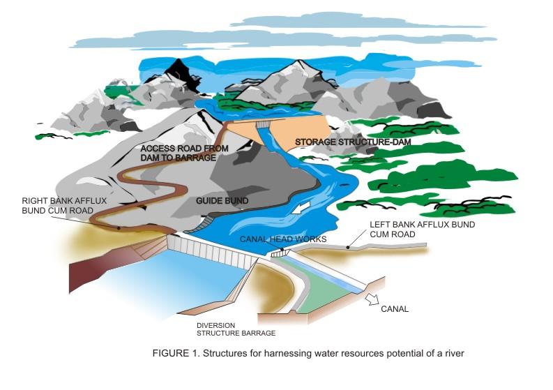
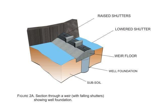
3 Instructional objectives On completion of this lesson, the student shall learn: 1. The hydraulic structures built to divert water from a river, like a barrage or a weir 2. The different steps to be followed for planning, layout, design and construction of barrages 3. The various aspects of investigation necessary for planning a diversion structure 4. How to choose the location and alignment of a proposed diversion structure 5. How to determine the characteristic dimensions of the different parts of a barrage 6. What are the appurtenant structures that have to be provided with a barrage Introduction In order to harness the water potential of a river optimally, it is necessary to construct two types of hydraulic structures, as shown in Figure 1. These are: 1. Storage structure, usually a dam, which acts like a reservoir for storing excess runoff of a river during periods of high flows (as during the monsoons) and releasing it according to a regulated schedule. 2. Diversion structure, which may be a weir or a barrage that raises the water level of the river slightly, not for creating storage, but for allowing the water to get diverted through a canal situated at one or either of its banks. Since a diversion structure does not have enough storage, it is called a run-of-the river scheme. The diverted water passed through the canal may be used for irrigation, industry, domestic water needs or power generation. In this lesson, we shall discuss about the planning, layout and construction aspects of diversion structures, particularly barrages. This is because a weir, which is a raised hump-like structure across the river usually associated with small shutters for flow control (Figure 2a), may be suitable for very small diversion works but for larger rivers with more flexibility on flow control, a barrage (Figure 2b) is desirable. As may be observed from the figures, a barrage is actually a gated form of a weir and the table below lists the relative merits of each of the structure over the other.
4

5 Weir Barrage Low cost Low control on flow No provision for transport communication across the river Chances of silting on the upstream is more Afflux created is high due to relatively high weir crests High cost Relatively high control on flow and water levels by operation of gates Usually, a road or a rail bridge can be conveniently and economically combined with a barrage wherever necessary Silting may be controlled by judicial operation of gates Due to low crest of the weirs (the ponding being done mostly by gate operation), the afflux during high floods is low. Since the gates may be lifted up fully, even above the high flood level.
6 In general, the trend in India for most of the modern water resources project involving diversion of water through a canal involves construction of a barrage, since a slightly more investment can bring in much larger benefits in the long run. Weirs may be used for very small scale hydraulic works. In the subsequent sections of this lesson, we shall discuss only barrages and interested readers may refer to any standard textbook for details of weirs Barrages in different river regimes A number of barrages have been constructed in this country over the past half a century or so and they may be classified as being located in the following four types of river regimes: Mountainous and sub-mountainous Alluvial and deltaic The barrages constructed in these different types of rivers have their own advantages and disadvantages, as discussed below: The mountainous and sub-mountainous regions are suitable for locating a diversion structure for hydroelectric power schemes due to the availability of high heads and less siltation problems. However, there could be problems at the head works (intake) of the canal due to possible withdrawal of shingles and arrangements have to be made for the elimination of these. For irrigation canals taking off from the head-works, the service area (where the water would actually be used for irrigation) will start after some distance from the head-works and the idle length of the canal would be more. Further, there would be more number of drainages (hilly streams and torrents) that has to be crossed by the canal as compared to the one in the plains. It is also natural for the canal in the mountainous and sub-mountainous regions to negotiate terrain with relatively larger changes in elevation than the canals passing through alluvial or deltaic stretches of rivers. For power canals (usually called power channels) the difference in elevations can be effectively utilized by generating hydro-power. In case of irrigation canals, a large number of drops have to be provided. Of course, many irrigation canal drops have been combined with a hydro-electric power generating unit, as shown in Figure 3.

7 4.1.2 Steps for planning, layout, design, construction and operation of barrages It is essential for the successful working of a barrage, or any hydraulic structure for that matter, depends on a proper selection of the location, alignment, layout, design and operation of the structure. Hence, the following aspects have to be carefully looked in to, which have been discussed in detail in the subsequent sections of this lesson: Site investigation and data collection Location and alignment selection of the barrage axis Planning, layout of the barrage and its appurtenant structures Hydraulic designs Structural designs River training works associated with barrages Head regulator for canal intake Instrumentation Construction Maintenance and operations.
8 4.1.3 Site investigation and data collection Once it has been decided to establish a barrage for flow diversion from a certain river, proper investigations should be carried out and necessary data should be collected in a systematic way. These aspects are primary to the establishment of a barrage and are necessary to avoid any delay in selecting location, layout and design of the structure. The expenditure in collecting accurate information before designs and construction forms a very small fraction of the total cost of the project, but has a great value in preparing safe and economic designs in a short span of time. In this respect, the Bureau of Indian Standards Code IS: Criteria for investigation, planning and layout for barrages and weir may be followed, from which the following have been extracted. Investigations and the corresponding data are generally collected in two stages: primary and detailed. The primary investigations include the following, which are used to choose not one, but a couple of alternate sites for the proposed barrage project within some reasonable length along the river. A study of these preliminary data would help to earmark one of the few alternative sites. Study of available maps and satellite imageries These maps are generally the survey of India topo-sheets which are published by the agency in a particular format and scale. The survey of a region gets repeated after 30 to 40 years and, hence, it would be wise to collect not only the latest topo-sheet of the project region but also the past surveyed maps which would give an idea of the course of the river in the past. Similarly, the satellite imageries of the river not only in the recent past, but also of as many years back (such imageries are usually available since 1980s) may be collected for studying the physical behaviour of the river like lateral migration, width change, etc. Regional and site geology The geology of the project area helps to identify the possibility of a stable foundation of the hydraulic structure, in this case a barrage. Hence the study of this aspect with particular reference to adverse. Geological formations like faults, fractured zones, shear zones, fissures, solution cavities, seismicity, slide zones, etc. should be studied. Study of foundation strata Data on the physical characteristics of the riverbed soil or rock from trial pits, trenches and bore holes or from the vertical banks of the rivers should be collected in and around the project region. This data would enable the designer to determine the type of structure necessary at each possible site and hence an economical design may be proposed.
9 Study of available hydrological data For correct assessment of the water potential at a certain site, it is essential that the available hydrological data, such as rainfall records in the catchment, river gauges and discharges, peak flows etc. must be studied. Primarily, an assessment of the available 10-daily and monthly runoff and peak flow should be assessed at the location of the river where the barrage is proposed to be built. Assessment of water needed for diversion The amount of water that needs to be diverted considering the basic requirement (agricultural, industrial or domestic) and any future increment thereof should be carefully assessed. This would enable the designer to establish well-proportioned canal headworks for intaking water into the main canal and fix the necessary levels on either side of the works required for conveying the required amount of water. Effect of the barrage on environment and ecology It is necessary to avoid any adverse effect on the environment, to study the fallout of locating a barrage across the river. Possible erosion of banks and river meandering on the upstream and downstream of the proposed project site an account of construction and operation of the barrage may be investigated. Limitations on water withdrawal In most of the rivers in India, the amount of water may not be sufficient at least during some seasons to satisfy all the potential demands. In fact, the demand of the lower river reaches, also called riparian rights, has to be honoured before deciding on the quantity of water that is proposed to be withdrawn. A system of water laws, interstate treaty on sharing of water, etc. already enacted has to be recognized. Further, a careful evaluation is to be made of the human socio-economic factors in the area, their present state, their trends, and to satisfy the corresponding needs and requirements of the society. Availability of construction material The construction material that is available readily should be assessed which helps the designer to plan the type of material to be used for constructing the barrage. Communication to the site of work While the choice of the final site for locating the structure should be made mainly from considerations of engineering and geology, due consideration should also be given for communication works for easy accessibility and economic transportation of materials to the site of work. The above considerations furnish the general investigations and data requirement that is needed for selecting the possible sites for the location of the barrage.
10 Some of the viable alternative sites may be eliminated based on the data of topography, environmental, geology, and foundation, etc. Once a particular site has been chosen from amongst a few plausible options, a detailed investigation is carried out which would help in the hydraulic and structural design aspects of the barrage and its appurtenant structures. If gauge and discharge observations are not available for the site earmarked, it should be immediately started. The following list mentions the detailed investigations that are to be done in order to collect necessary data. Detailed topographical survey The survey of India contour maps (often called topo-sheets) are generally drawn to the scale of 1 in or 1 in with the contour intervals in the range of 20m in the former and 5m in the latter. Clearly, this accuracy is not enough while designing a hydraulic structure, especially a barrage, whose height itself may be in the range of 5 to 10 meters, and the variation of water level in the pond much less than that. Hence, a detailed survey of the project area may have to be done in scales of at least 1 in 5000 with contours not more than at 0.5m interval. Of course, the contours need not be done above some height, say 2.5 to 3 meters, above the high flood level. The contour plan shall extend up to about 5km on the upstream and downstream of the site and up to an adequate distance on both the flanks up to which the effect of pond is likely to extend. Apart from the detailed elevation contours, the cross-sections of the river have to be taken at the axis of the barrage at the proposed site and at regular intervals, say 100m, up to about 2km upstream and 1km downstream of the site. The cross sections may be spaced at 5 to 20m apart depending upon the topography of the river. In the deep channel portion of the river, the cross levels may be taken closer. Hydro-meteorological data This aspect of data collection is very important for the two entirely different aspects of studies for a river diversion structure. The first is to assess the amount of high flood (called the design flood) that is likely to pass through the barrage for a given probability of occurrence. This would enable the designer to provide sufficient spillway capacity for the barrage. The design flood may be analysed by a study of rainfall records of as many meteorological stations as possible in the vicinity of the site and applying the unit hydrograph analysis. If peak flow data for many years are available, then a flood frequency study may also be made. The second aspect relates to the minimum available discharge (or runoff of the river at project site) that may be diverted. Hence this evolves from a study of the low flows, and estimates of the dependable yield. If the data available is inadequate, a correlation could be established for utilizing the longterm data available for a nearby site of the river. Sediment concentration data For planning sediment exclusion devices at the head-works and in the canal system and to evolve a suitable gate regulation for satisfactory sediment passing down the barrage, it is necessary to have data on the sediment load carried by the river for as such period as possible. It is especially required for the flood season when the sediment carried
11 would be more. If the quantity of sediment brought by the river is excessive, the pond levels have to be fixed carefully taking the sediment data into account. This is especially important when the pondage (the capacity of the pool behind the barrage) is proposed to be provided to meet diurnal power fluctuations also. Pond survey The area that is going to be submerged up to normal pond level or within the afflux bunds that shall be acquired, has to be surveyed for working out rehabilitation strategy and compensation amounts. If some forest land is getting submerged, then permission of the Department of Forests and Environment, government of India has to be acquired. Study of navigation and fish Data regarding the type of boats and ships passing through the river has to be collected in order to assess the possibility of providing navigation locks (Figure 4). Data regarding the quantity of migratory fish also needs to be collected in order to study the feasibility of providing a fish ladder (Figure 5).
12 Study for power generation Since a barrage causes heading up of water, there is always a possibility of utilizing the difference in water levels between the upstream pool and the downstream river level to generate hydropower. The difference in water levels is higher during the non-monsoon periods, when the total river flow is less and, consequently, the water level of the natural river downstream is quite low but the gates of the barrage help to keep the pool level high. Bulb turbines (as shown for canal falls power house, Figure 3) which can utilise head difference between one to fifteen meters can be installed in some bays of the barrage to generate power. Theoretical investigation for minimum available 10-daily flows in 50%, 75% and 90% of the year and the normal differential head available in different months have to be studied to assess the power generating potential of a barrage power house. Study for provision of a rail or a road bridge across the barrage The requirement of connectivity between the two sides of the river at the point where a barrage is being proposed to be built may lead to decisions regarding provisions of a rail or a road bridge across the barrage. The volume of rail or road traffic would help to determine single or double lanes for the respective modes of transport Location and alignment selection The location for a barrage should be decided on considerations of suitability for the main structure and its appurtenant works, like silt removing devices and intake for canals (also called canal head regulators). An ideal location would be that which
 intending to divert")
13 satisfies the requirements of all the three components. Some of the points that have to be kept in mind in selecting an appropriate location for a barrage are as follows: The canal head regulators (or head-works, as they are called) intending to divert water to a canal for irrigation has to be planned such that full command may be achieved by a barrage or weir of reasonable height. The combined cost of construction of head-works and that of the canal from the barrage up to the point where the water is first used for irrigation should be small. Sometimes, a favourable location for fixing the site for a barrage and canal headworks may have to be abandoned due to large quantities of rock excavation required. The river reach at the proposed location should be straight, as far as possible, so that velocities may be uniform and the sectional area of the river fairly constant. The banks should preferably be high, well defined and non-erodible. This will ensure a more or less straight flow to the barrage from the upstream. If such a site is available, it may need very small or practically no guide bunds. In case of high banks, the country side will not be submerged during high floods and a considerable saving in the cost of flood protection embankment may be effected. For barrages to be located in alluvial river reaches with meandering tendencies, the nodal points have to be ascertained. Nodal point is the portion of a meandering river which is more or less fixed in space (Figure 6). A nodal point may be decided by superimposing the survey maps or corresponding satellite imageries of the river for as many years as possible.
14 For locating a barrage in a curve of a river, the off-taking canal may be located in the downstream end of the concave bank, which would help in drawing less sediment in to the canal. If it is a necessity to locate an off-taking canal on the convex bank (as may be required for irrigating an area on this side of the river), then proper silt excluding devices have to be designed since a convex bank of a curved river is prone to sediment accumulation Planning and layout A barrage, by definition, is a weir structure fitted with gates to regulate the water level in the pool behind in order to divert water through a canal meant for irrigation, power generation, flow augmentation to another river, etc. By following the general guidelines mentioned in section 4.14, the location and alignment of the barrage axis and that of the canal headworks may be decided but the other details, like the width of the barrage and headworks, levels of weir crests, lengths of weir floors, river training works, pond level etc. have to be finalized based on the hydraulic conditions and geologic characteristics of the river bed and banks of the site. This section is devoted to these planning and layout concepts of a barrage project consisting of the main structure and its appurtenant works. The planning part decides the various parameters necessary for designing the structures. Further, planning is also necessary for chalking out a construction program. The major planning aspects are as follows: Design flood The diversion structure has to be designed in such a way that it may be able to pass a high flood of sufficient magnitude (called the design flood) safely. It is assumed that when the design flood passes the structure all the gates of the structure are fully open and it acts like a weir across the river with only the obstruction of the piers between the abutments. The abutments are the end walls at two extremes of the structure and the length in between the two is termed as the waterway. Naturally, a high design flood would necessitate a longer waterway. In general, a design flood of 1 in 50 years frequency has been recommended for design of all items except free board for which a minimum of 500 year frequency flood or the Standard Project Flood has been recommended as per Bureau of Indian Standard Code IS: 6966 (Part1) Hydraulic Design of Barrages and Weirs guidelines, some of the barrages built in the past have considered very high design floods, as may be seen from the data given below:
15 Barrage across river Gondak Godawari Kosi Sone Design flood frequency 1in 220 years 1in 200 years 1 in 600 years 1 in 70 years Though a high design flood may ensure safety of the structure against large floods, there is a consequent adverse affect related to sediment deposition in the pool. This results from the fact that since a design flood is expected to pass once in that many years, with a full gate opening, the intervening years having lesser magnitude of floods would see the gates of the barrage being operated to raise the pond level at the desired elevation. Naturally, this would result in a slower velocity in the pool and a consequent deposition of suspended sediments. If sediment deposition continues for many consecutive years, they tend to form large mounds, called shoals, within the pool, not far upstream from the barrage bays. This phenomena, which has been noticed in many of the large barrages of India, like Farakka, Mahanadi, etc., can cause not only reduction in the pool volume but more importantly, may cause obstruction to the free flow of the river that is approaching the barrage. This results in what is called the washing of bays, with the flow through the bays directly downstream of the shoals being reduced and the excess flow passed through the other bays. As a result, it causes inclination of the approaching flow to the barrage which may cause other undesired phenomena. It has been observed that barrages with large shoal formations just upstream have flow inclinations to the extent of 60 0 or more to a normal through the barrage axis. Afflux If the flood in the river is less than the design flood, then some of the gates would be fully opened but the remaining opened to such an extent which would permit the maintaining of the pond level. However, when a design flood or a higher discharge through the barrage structure, all the gates have to be opened. Nevertheless, the structure would cause a rise in the water level on the upstream compared to level in the downstream at the time of passage of a high flood (equal to or more than the design flood) with all the gates open. This rise in water level on the upstream is called afflux. The amount of afflux will determine the top levels of the guide bunds and marginal bunds, piers, flank walls etc. Naturally a smaller waterway would result in larger afflux and vice versa. Hence, reduction in water way may cause in lowering the cost of the barrage structure but may result in higher afflux and a resulting larger height of bunds and piers.

16 Free Board Once the permissible afflux is decided, the necessary water way can be accordingly worked out and the upstream water level estimated for the design flood. Over the gauge-discharge curve on the downstream side and estimated on the upstream, sufficient Free Board has to be provided so that there is no overtopping of the components like abutments, piers, flank walls, guide bunds, afflux bunds etc. The Free Board to be provided depends on the importance of the structure generally, 1.5 to 2 m Free Board above the affluxed water level on the upstream and above the high flood level on the downstream is provided. A freeboard is provided over an affluxed water level due to a flood with 1 in 500 year frequency.

17 Pond Level Pond level is the level of water, immediately upstream of the barrage, which is required to facilitate withdrawal of water into the canal with its full supply. The pond level has to be carefully planned so that the required water can be drawn without difficulty. By adding the energy losses through the head regulator to the Full Supply Level of the canal at its starting point just downstream of the canal head-works, the pond level is evaluated.

18 The provision of a high pond level with an elevation almost equal to the high flood level or above has to be planned very carefully since such a provision is likely to induce shoal formation on the upstream. This has happened in the Durgapur Barrage on river Damodar. Waterway As discussed earlier, waterway, or the clear opening of a barrage to allow flood flow to pass has a bearing on the afflux. Hence, a maximum limit placed on the afflux also limits the minimum waterway. Many a times, the Lacey s stable perimeter for the highest flood discharge is taken as the basis of calculating the waterway. However, it should be remembered that Lacey s formula is based on studies of canals in the alluvial regime and may not be quite correct for large rivers, and also for rivers in boulder or clayey reaches. Nevertheless, application of the Lacey s waterway would require the following calculations as given in Bureau of Indian standard Code IS: Guidelines for hydraulic design of barrages and weirs: Part 1 Alluvial Reaches. P = 4.83 Q 1/2 (1) Where Q is the design flood discharge in m 3 /s for the 50 year frequency flood. In the case of rivers in bouldery reaches, the width available at the site is limited by the firm banks. For meandering rivers in alluvial reaches, a factor is usually multiplied with the perimeter obtained by Lacey s formula, which is called the looseness factor, as given below
19 Silt Factor, f Looseness Factor < to to to 0.6 Silt factor f is calculated by knowing the average particle size d 50 is in mm of the soil from the following relationship f =1.76 (d 50 ) 1/2 (2) By limiting the waterway, and consequently increasing the velocity and discharge per unit width, the shoal formation in the pond upstream of the barrage can possibly be minimized. However, it has an adverse effect also since increase in the intensity of discharge, requires longer solid apron and deeper sheet piles due to higher expected scour depths. Nevertheless, the performance of many barrages has led to the general observation that high looseness factor, more than about 1.0, results in shoal formation in the upstream pool. Hence many recent barrages have been designed with a low looseness factor, nearing 0.5. However, there is a need for a systematic study to evolve a scientific analysis for evaluating the waterway. A restricted waterway for a barrage is obtained by the use of guide bunds, approach and afflux embankments in Figure 10.

20 A brief discussion of the above works, called river training works, is given in the following section. River training works The river training works for barrages are required to achieve the following; 1. Prevent out flanking of the structure 2. Minimize cross flows through the barrage 3. prevent flooding by the river lands upstream 4. provide favourable curvature of flow at the head regulator from the point of sediment entry into the canal, and 5. guide the river to flow axially through the barrage or weir As was seen in the section on waterway, it is necessary at many instances to narrow down and restrict the course of the river through the barrage and it is achieved by the use of the river training works. Proper alignment of guide bunds is essential to ensure satisfactory flow conditions in the vicinity of the barrage. In case of wide alluvial banks, the length and curvature at the head of the guide bunds should be kept such that the worst meander loop is kept away from either the canal embankment or the approach embankment. If the alluvial bank is close to the barrage, the guide bunds may be

21 connected to it by providing suitable curvature, if necessary. If there is any out-crop of hard strata on the banks, it is advisable to tie the guide bunds to such control points. Two typical guide bund layouts are shown in Figure 11. The dimensions given in Figure 11 are preliminary, and model studies have to be carried out for fixation of final sizes for any particular project depending upon the prevalent site conditions.
 in order to: Maintain a clear and well defined river channel towards the canal head regulator To enable")
22 Crest levels of spillway and undersluice bays The bays of a barrage are in the shape of weirs or spillways and the crest levels of these have to be decided correctly. Some of the bays towards the canal end of the barrage are provided with lower crest (Figure 12) in order to: Maintain a clear and well defined river channel towards the canal head regulator To enable the canal to draw silt free water from surface only as much as possible To scour the silt deposited in front of the head regulator The set of undersluice bays withlow crest elevations are separated from the set of spillway bays witha small weir hump by a long wall, called the divide wall. The layout of a barrage and its appurtenant structures can be seen from a typical plan view shown in Figure 13. The important components of a barrage are discussed below:
23 Spillway bays This is the main body of the barrage for controlling the discharges and to raise the water level to the desired value to feed the canals. It is a reinforced concrete structure designed as a raft foundation supporting the weight of the gates, piers and the bridge above to prevent sinking into the sandy river bed foundation. A typical section of a spillway bay is shown in Figure 14.
24 Undersluice bays These low crested bays may be provided on only one flank or on bothflanks of the river depending upon whether canals are taking-off from one or both sides. The width of the undersluice portion is determined on the basis of the following considerations. It should be capable of passing at least double the canal discharge to ensure good scouring capacity It should be capable of passing about 10 to 20 percent of the maximum flood discharge at high floods It should be wide enough to keep the approach velocities sufficiently lower than critical velocities to ensure maximum settling of suspended silt load. Undersluices are often integrated withrcc tunnels or barrels, called silt excluders, extending up to the widthof the Canal Head Regulator, as can be seen from Figure 13. These tunnels are provided in order to carry the heavier silt from a distance upstream and discharge it on the downstream, allowing relatively clear water to flow above from which the Canal Head Regulator draw its share of water. Typical sections of undersluices with and without silt excluder tunnel are shown in Figures 15 and 16.
25 River sluice bays River sluices are a set of sluices similar to the undersluices located in between the undersluice and spiilway bays and separated from them by means of divide walls. These are generally provided in long barrages (that is, in wide rivers) for simplifying the operation of gates during normal floods and to have better control on the river. The section of river-sluice bays would generally be similar to that of undersliuce bays without silt excluding tunnels. Cut-off Cut-offs are barriers provided below the floor of the barrage both at the upstream and the downstream ends. They may be in the form of concrete lungs or steel sheet-piles, as observed from the figures 14, 15 and 16. The cut-offs extend from one end of the barrage up to the other end (on the other bank). The purpose of providing cutoff is twofolds as explained below. During low-flow periods in rivers, when most of the gates are closed in order to maintain a pond level, the differential pressure head between upstream and downstream may cause uplift of river bed particles (Figure 17a). A cutoff increases the flow path and reduces the uplift pressure, ensuring stability to the structure (Figure 17b).


26 During flood flows or some unnatural flow condition, when there is substantial scour of the downstream riverbed, the cutoffs or sheet piles protect the undermining of the structures foundation (Figure 18).
27 Pier Piers are provided between each bay. The gates operate through the groove provided in the piers. Usually, there are two sets of grooves, the upstream being called the Stop Log groove and the downstream one being called the Main Gate or Service gate groove. The piers are constructed usually monolithic with the floor (raft), and extend usually from the upstream end to the downstream end solid floor of the spillway (or under sluice/river sluices), as may be observed from Figure 2B. The piers have to be high enough to hold the gates clear off the maximum flood level while making ample allowance for passing any floating debris under the raised gates. Divide wall The divide wall is much like a pier and is provided between the sets of undersluice or river sluice or spill bays. The main functions of a divide wall: It separates the turbulent flood waters from the pocket in front of the canal head. It helps in checking parallel flow (to the axis of the barrage) which would be caused by the formation of deep channels leading from the river to the pocket in front of the sluices. The length of the divide wall on the upstream has to be such as to keep the heavy action on the nose of the divide wall away from the upstream protection of the sluices and also to provide a deep still water pond in front of the canal head regulator. A typical section of a divide wall is shown in Figure 19.
28 Abutment The abutments form the end structures of the barrage and their layout depends upon the project features and topography of the site. The lengthof the abutment is generally kept same as the lengthof the floor. The top of the abutment is fixed withadequate free board over the upstream and downstream water levels. Flank wall In continuation of the abutments of the diversion structure, flank walls are provided bothon the upstream and downstream sides on boththe banks. The flank walls ensure smoothentry and exit of water and away from the diversion structure. The flank walls laid out in a flare withvertical alignment close to the abutment and a slope of 2H:1V or 3H:1V on the other end, as may be observed from the layout of the barrage shown in Figure 13. Return wall Return walls are generally provided at right angles to the abutment either at its end or at the flank wall portion, and extends into the banks to hold the bank or back-filling earth in place. Guide bunds The requirement of narrowing down and restricting wide alluvial river courses to flow axially through the barrage necessitates the use of guide bunds, as shown in Figure 10. Afflux bunds Afflux bunds are components of the diversion structures wherever necessary to protect important low lying properties adjacent to the structures from submergence due to affluxed high floods. Silt excluding devices As shown in the layout of a barrage (Figure 13), the silt excluding tunnels carry heavy silt down the river below the undersluices. Navigation Lock Since inland or river water navigation is economically more attractive for larger cargo, navigation facilities can be combined withthe barrage projects. This includes the provision of a navigation channel withnavigation locks suitably incorporated to allow passage of crafts to move from upstream to downstream and vice versa (Figure 4).
29 Fish pass Some barrages require providing special structures to allow migratory fishes to flow up and down the river through structures called Fish Passes or Fish Locks (Figure 5). Canal Head Regulator The water that enters a canal is regulated through a Head Regulator. A typical cross section through a regulator is shown in Figure 9. As it is desirable to exclude silt as much as possible from the head regulator, the axis of the head regulator is laid out at an angle from 90 0 to to the barrage axis as recommended in Bureau of Indian Standards code IS : 6531(1972) Criteria for design of canal head regulators. A typical layout of a head regulator is shown in Figure Finalisation of barrage layout through model studies It may be realised that a being a structure spanning across a river, may cause enormous changes to the river hydraulics and morphology. Much of this is dynamic, since the floods every year would generally be of different magnitude or duration and
30 accordingly the gate operation would be different each time. Hence the planning and layout decided from the general principles discussed earlier in this lesson may only be taken as a guideline. The final position, location, layout, alignment of each component of the structure and in relation to each other has to be done through model studies. The Bureau of Indian Standard code IS 14955: 2001 Guidelines for hydraulic model studies of barrages and weirs lays down the basic principles of model studies and could be followed to finalise the layout of a particular barrage project.
Created by Simpo PDF Creator Pro (unregistered version) Asst.Prof.Dr. Jaafar S. Maatooq
 Asst.Prof.Dr. Jaafar S. Maatooq") Lect.No.9 2 nd Semester Barrages, Regulators, Dams 1 of 15 In order to harness the water potential of a river optimally, it is necessary to construct two types of hydraulic structures, as shown in Figure
Lect.No.9 2 nd Semester Barrages, Regulators, Dams 1 of 15 In order to harness the water potential of a river optimally, it is necessary to construct two types of hydraulic structures, as shown in Figure
Irrigation Structures 1
 CHAPTER 8 Irrigation Structures 1 Dr. M. R. Kabir Professor and Head, Department of Civil Engineering University of Asia Pacific (UAP), Dhaka LECTURE 20 Diversion Head Works Definition: The works, which
Using SWAT Module in the Design of Submerged Weir on narrow rivers having high flood discharge
 Using SWAT Module in the Design of Submerged Weir on narrow rivers having high flood discharge Presented by Er. Narendra Kumar Tiwary, B.Tech IIT Delhi, M.Tech NIT(Pat), Ph.D Scholar IIT Delhi Professor,
Solution for Irrigation Engineering
 Solution for Irrigation Engineering December 2015 Index Q.1) a). 2-3 b).3-5 c).5-6 d).6-8 e).9-10 Q.2) a).10-11 b). 12-14 c). 14-15 Q.3) a). 15-16 b). 17 c). 18 Q.4) a). N.A b). N.A c). N.A Q.5) a).20-22
Irrigation Structures 2. Dr. M. R. Kabir
 CHAPTER 9 Irrigation Structures 2 Dr. M. R. Kabir Professor and Head, Department of Civil Engineering University of Asia Pacific (UAP), Dhaka LECTURE 22 What is Cross Drainage Works? In an irrigation project,
Fig: Alignment of a ridge or watershed canal (Head reach of a main canal in plains)
") SYSTEM OF IRRIGATION CANAL CHAPTER 6 Alluvial Soil and Non-Alluvial Soil The soil which is formed by transportation and deposition of silt through the agency of water, over a course of time, is called
SYSTEM OF IRRIGATION CANAL CHAPTER 6 Alluvial Soil and Non-Alluvial Soil The soil which is formed by transportation and deposition of silt through the agency of water, over a course of time, is called
A dam and a reservoir are complements of each other.
 A dam is a hydraulic structure of fairly impervious material built across a river to create a reservoir on its upstream side for impounding water for various purposes. A dam and a reservoir are complements
Asst.Prof.Dr. Jaafar S. Maatooq. 1 st Semester HYDRAULIC STRUCTUER, KINDS & FUNCTIONS 1 of 26
 1 st Semester HYDRAULIC STRUCTUER, KINDS & FUNCTIONS 1 of 26 1 st Semester HYDRAULIC STRUCTUER, KINDS & FUNCTIONS 2 of 26 Water is often more useful to people when it is properly controlled, conveyed,
Tulsi Prasad Phuyal Research Engineer Hydro Lab, Pulchowk, Lalitpur, Nepal
 Himalayan Small Hydropower Summit (October 12-13, 2006), Dehradun SMALL HYDROPOWER AND HEADWORKS MODELLING Tulsi Prasad Phuyal Research Engineer Hydro Lab, Pulchowk, Lalitpur, Nepal Manohar Shrestha Deputy
Temporary Watercourse Crossing: Fords
 Temporary Watercourse Crossing: Fords DRAINAGE CONTROL TECHNIQUE Low Gradient Velocity Control Short Term Steep Gradient Channel Lining Medium-Long Term Outlet Control Soil Treatment Permanent [1] [1]
(b) Discuss in brief shaft spillway with neat sketches. Marks 04. OR Q (2) Explain in brief USBR stilling basin. Marks 08
 Discuss in brief shaft spillway with neat sketches. Marks 04. OR Q (2) Explain in brief USBR stilling basin. Marks 08") (b) Discuss in brief shaft spillway with neat sketches. Marks 04 OR Q (2) Explain in brief USBR stilling basin. Marks 08 Stilling Basins The basins are usually provided with special appurtenances including
(b) Discuss in brief shaft spillway with neat sketches. Marks 04 OR Q (2) Explain in brief USBR stilling basin. Marks 08 Stilling Basins The basins are usually provided with special appurtenances including
Dam Safety and Low Cost Spillway Designs
 Dam Safety and Low Cost Spillway Designs By F. Lempérière & J.P. Vigny (Hydrocoop France) THE CHALLENGE 5 th International Conference on Dam Engineering Lisbon 14-16 February 2007 Increasing dams safety
Water distribution within the canal network
 Structures for water control and distribution 15 Chapter 4 Water flowing in a secondary irrigation canal can be divided over the tertiary canal network in several ways. One way is to divide the flow proportionally
Springshed Management Training Curriculum 2016 The Springs Initiative
 Springshed Management Training Curriculum 2016 The Springs Initiative SESSION TITLE: BMPs for Protection, Restoration & Recharge SECTION: Application of Knowledge MODULE: BMPs for Recharge, Restoration,
NOT-MODELLING FOR STORMWATER AROUND THE KAIKOURA ALLUVIAL FANS
 NOT-MODELLING FOR STORMWATER AROUND THE KAIKOURA ALLUVIAL FANS Mark Pennington Pattle Delamore Partners Limited, Kaikoura, New Zealand ABSTRACT The Kaikoura plains are formed by a process of coalescing
Fabric Drop Inlet Protection
 Fabric Drop Inlet Protection SEDIMENT CONTROL TECHNIQUE Type 1 System Sheet Flow Sandy Soils Type 2 System Concentrated Flow Clayey Soils [1] Type 3 System Supplementary Trap Dispersive Soils [1] Block
STANDARDS/MANUALS/ GUIDELINES FOR SMALL HYDRO DEVELOPMENT
 STANDARDS/MANUALS/ GUIDELINES FOR SMALL HYDRO DEVELOPMENT General Works Guidelines for Investigation of SHP Projects Sponsor: Ministry of New and Renewable Energy Govt. of India Lead Organization: Alternate
4.2 Discharge measurement by Velocity Area Method (Chitale, 1974)
") 4.2 Discharge measurement by Velocity Area Method (Chitale, 1974) This method comprises measuring the mean velocity V and the flow area 'A' and computing the discharge Q from the continuity equation. The
4.2 Discharge measurement by Velocity Area Method (Chitale, 1974) This method comprises measuring the mean velocity V and the flow area 'A' and computing the discharge Q from the continuity equation. The
Module 3. Irrigation Engineering Principles. Version 2 CE IIT, Kharagpur
 Module 3 Irrigation Engineering Principles Lesson 8 Conveyance Structures for Canal Flows Instructional objectives On completion of this lesson, the student shall learn the following: 1. The need for structures
Control and Mitigation of Drinking Water Intake Problems along Nile River
 International Network on Sustainable Water Management i n D e v e l o p i n g C o u n t r i e s ex)(ceed SWINDON Control and Mitigation of Drinking Water Intake Problems along Nile River Gamal A. Sallam,
Temporary Watercourse Crossing: Culverts
 Temporary Watercourse Crossing: Culverts DRAINAGE CONTROL TECHNIQUE Low Gradient Velocity Control Short Term Steep Gradient Channel Lining Medium-Long Term Outlet Control Soil Treatment Permanent Symbol
Appendix E: Bridge Site Information Summary
 BRIDGE MANUAL E - 1 APPENDIX E: BRIDGE SITE INFORMATION SUMMARY Appendix E: Bridge Site Information Summary Table of Contents Notes..E 3 Section 1: Basic Information..E 4 Section 2: River Data..E 8 Section
ONE DIMENSIONAL DAM BREAK FLOOD ANALYSIS FOR KAMENG HYDRO ELECTRIC PROJECT, INDIA
 ONE DIMENSIONAL DAM BREAK FLOOD ANALYSIS FOR KAMENG HYDRO ELECTRIC PROJECT, INDIA S. Masood Husain Nitya Nand Rai Director Assistant Director Foundation Engineering & Special Analysis Directorate Central
Highway Drainage 1- Storm Frequency and Runoff 1.1- Runoff Determination
 Highway Drainage Proper drainage is a very important consideration in design of a highway. Inadequate drainage facilities can lead to premature deterioration of the highway and the development of adverse
Module 2 Measurement and Processing of Hydrologic Data
 Module 2 Measurement and Processing of Hydrologic Data 2.1 Introduction 2.1.1 Methods of Collection of Hydrologic Data 2.2 Classification of Hydrologic Data 2.2.1 Time-Oriented Data 2.2.2 Space-Oriented
Dams are generally constructed in the mountainous reach of the river where the valley is narrow and the foundation is good.
 [ DAMS ] 1 of 26 1-Definition : A dam is a hydraulic structure of fairly impervious material built across a river to create a reservoir on its upstream side for impounding water for various purposes. A
Types of Hydropower Facilities
 Types of Hydropower Facilities 1 Impoundment Hydropower- uses a dam to store water. Water may be released either to meet changing electricity needs or to maintain a constant water level. 2 Run-of-River
Earth Brickwork Concrete Plain Radial Drum Roller Flap. fixed. Weirs Barrages. mobile. rockfills. Gravity butress Arch Arch-gravuty Cupola.
 Dams type 1 Weirs Barrages fixed mobile Earth Brickwork Concrete Plain Radial Drum Roller Flap embankment Earthfills rockfills Dams Concrete gravity Arch Gravity butress Arch Arch-gravuty Cupola 2 Dams
ILLINOIS URBAN MANUAL PRACTICE STANDARD TEMPORARY STREAM CROSSING (no.) CODE 975. Source: Hey and Associates, Inc.
 CODE 975. Source: Hey and Associates, Inc.") ILLINOIS URBAN MANUAL PRACTICE STANDARD TEMPORARY STREAM CROSSING (no.) CODE 975 Source: Hey and Associates, Inc. DEFINITION A bridge or culvert crossing installed across a stream or watercourse for short-term
ILLINOIS URBAN MANUAL PRACTICE STANDARD TEMPORARY STREAM CROSSING (no.) CODE 975 Source: Hey and Associates, Inc. DEFINITION A bridge or culvert crossing installed across a stream or watercourse for short-term
PRELIMINARY DESIGN OF THE HYDRAULIC STRUCTURES DAM IN THE PISÃO RIVER
 PRELIMINARY DESIGN OF THE HYDRAULIC STRUCTURES DAM IN THE PISÃO RIVER Margarida Isabel Godinho Sobral Department of Civil Engineering and Architecture, Instituto Superior Técnico - Lisbon, Portugal SUMMARY
Water Balance Assessment of the Roseires Reservoir
 Kamalddin E. Bashar 1 and Mohanad O. Mustafa 2 1 UNESCO-Chair in Water Resources, Khartoum, Sudan 2 Ministry of Irrigation and Water Resources, Sudan Abstract Roseires Reservoir on the Blue Nile River
FRST 557 Lecture 7b Cross Drainage Structures: Culverts and Bridges
 FRST 557 Lecture 7b Cross Drainage Structures: Culverts and Bridges Lesson Background and Overview: The last lesson introduced the topic of water management relative to forest roads and further explored
Small Hydro based energy generation
 Workshop on Capacity Development Program for Afghan Women (Clean Energy Access) Small Hydro based energy generation G Anil Head Small Hydro Power Dn., Energy Management Centre, Trivandrum 695017, Kerala,
THE CONSTRUCTION PHASES OF THE NEW NAGA HAMMADI BARRAGE COFFERDAMS
 Ninth International Water Technology Conference, IWTC9 2005, Sharm El-Sheikh, Egypt 355 THE CONSTRUCTION PHASES OF THE NEW NAGA HAMMADI BARRAGE COFFERDAMS Yasser Shawky ( 1), Hala Badawy ( 2) (1) Researcher,
Xayaburi Hydroelectric Power Project
 The MRC Regional Workshop on Discharge and Sediment Monitoring and Geomorphological Tool for the Lower- Mekong Basin, 21-22 22 October 2008 Xayaburi Hydroelectric Power Project TEAM Consulting Engineering
SMALL HYDRO BIG CHALLENGES Renewable Energy World Asia 2016 Martin P. Bieri. September 21, 2016
 SMALL HYDRO BIG CHALLENGES Renewable Energy World Asia 2016 Martin P. Bieri September 21, 2016 CONTENT Introduction Potential in Southeast Asia Challenges in Small Hydro Main Design Steps (Bad) Examples
Hydraulics of Jinnah Barrage; Existing Structure and Rehabilitation Alternatives
 Pak. J. Engg. & Appl. Sci. Vol. 4, Jan 2009 (p. 66-73) Hydraulics of Jinnah Barrage; Existing Structure and Rehabilitation Alternatives Z. A. Chaudhry 1 1 Professor, Civil Engineering Department, University
DPR GUIDELINES FOR ERM OF IRRIGATION PROJECTS
 DPR GUIDELINES FOR ERM OF IRRIGATION PROJECTS 1.0 INTRODUCTION RAJEEV SINGHAL Director NWA, CWC, Pune Modernisation of Irrigation Project includes extension, renovation & modernisation components of existing
Civil Engineering Department. 2 Marks Question and Answer. CE:2301:Irrigation Engineering
 Civil Engineering Department 2 Marks Question and Answer CE:2301:Irrigation Engineering 1 UNIT 1 INTRODUCTION 1) Define irrigation? Irrigation is defined as the science of artificial application of water
Distribution Restriction Statement Approved for public release; distribution is unlimited.
 CECW-ED Regulation No. 1110-2-8152 Department of the Army U.S. Army Corps of Engineers Washington, DC 20314-1000 Engineering and Design PLANNING AND DESIGN OF TEMPORARY COFFERDAMS AND BRACED EXCAVATIONS
COTTON CREEK CULVERT REPLACMENT
 COTTON CREEK CULVERT REPLACMENT Integrating Mobility with Environmental Innovation Located along a scenic section of Highway 3/95 in British Columbia, Moyie Bluffs, a 6.5 km stretch of inland highway had
Module 4 Hydraulic Structures for Flow Diversion and Storage
 Module 4 Hydraulic Structures for Flow Diversion and Storage Lesson 9 Reservoir Outlet Works Instructional objectives On completion of this lesson, the student shall learn: 1. Functions of outlet works
INCREASING LATERAL CAPACITY OF OLD BARRAGES INTRODUCING CABLES
 INCREASING LATERAL CAPACITY OF OLD BARRAGES INTRODUCING CABLES Ahmed Hashad 1, Yasser El-Hakem 1 and Eehab Khalil 2 1 Assistant Professor, Construction Research Institute, National Water Research Center,
ROLE OF THE FIRM IN THE PROJECT
 PROJECT DESCRIPTION Lake Loramie Dam is a Class I dam located in Lake Loramie State Park in Minster, Ohio. Lake Loramie originally served as the high feeder water supply for the Miami-Erie Canal that began
CHAPTER 3 Environmental Guidelines for WATERCOURSE CROSSINGS GOVERNMENT OF NEWFOUNDLAND AND LABRADOR DEPARTMENT OF ENVIRONMENT AND LABOUR
 GOVERNMENT OF NEWFOUNDLAND AND LABRADOR DEPARTMENT OF ENVIRONMENT AND LABOUR CHAPTER 3 Environmental Guidelines for WATERCOURSE CROSSINGS WATER RESOURCES MANAGEMENT DIVISION Water Investigations Section
BLOCKING AND FILLING SURFACE DRAINAGE DITCHES
 MINNESOTA WETLAND RESTORATION GUIDE BLOCKING AND FILLING SURFACE DRAINAGE DITCHES TECHNICAL GUIDANCE DOCUMENT Document No.: WRG 4A-1 Publication Date: 10/14/2015 Table of Contents Introduction Application
Abstract. 1. Main features of the Cua Dat scheme. Hong Giang VNCOLD. Hanoi Vietnam. the Northern Central The reservoir storage purposes: - water
 The diversion works for the Cua Dat CFRD in Vietnam Michel Ho Ta Khanh, Dinh Sy Quat, Prof Pham Hong Giang VNCOLD No 95/10 Chua Boc Street Dong Da District Hanoi Vietnam Abstract The Cua Dat CFRD is constructed
Performance Assessment of Taunsa Barrage Subsidiary Weir for Long Term Rehabilitation Planning
 Pak. J. Engg. & Appl. Sci. Vol. 7, Jul., 2010 (p. 65-70) Performance Assessment of Taunsa Barrage Subsidiary Weir for Long Term Rehabilitation Planning Zulfiqar Ali Chaudhry Civil Engineering Department,
SC-01 Surface Outlet and Baffle Sediment Basin
 Greenville County Technical Specification for: SC-01 Surface Outlet and Baffle Sediment Basin 1.0 Surface Outlet and Baffle Sediment Basin This Specification contains requirements for the design and construction
Performance improvement of headworks: a case of Kalignadaki A Hydropweor Project through physical hydraulic modelling
 Performance improvement of headworks: a case of Kalignadaki A Hydropweor Project through physical hydraulic modelling Dr. Ing. Meg B. Bishwakarma General Manager, Hydro Lab Pvt. Ltd., Nepal ABSTRACT: The
4. Present Activities and Roles
 4. Present Activities and Roles The present missions, authorities, activities and roles of the various agencies involved with flood protection, floodplain management and flood-damage reduction are identified
Block & Aggregate Drop Inlet Protection
 Block & Aggregate Drop Inlet Protection SEDIMENT CONTROL TECHNIQUE Type 1 System Sheet Flow Sandy Soils Type 2 System [1] Concentrated Flow Clayey Soils Type 3 System Supplementary Trap Dispersive Soils
Narora Weir A Historical Perspective of Piping Theory
 Narora Weir A Historical Perspective of Piping Theory Kevin S. Richards, Ph.D., L.P.G. Senior Advisor USACE - Risk Management Center September 23, 2015 US Army Corps of Engineers BUILDING STRONG Outline
Chapter 4. Main problems in a canal network 4.1 INTRODUCTION
 Canals 21 Chapter 4 4.1 INTRODUCTION This chapter looks at problems which are frequently encountered in irrigation canal systems. Some of these are described in detail. The last section of this chapter
USE OF GABIONS IN SMALL HYDRAULIC WORKS
 USE OF GABIONS IN SMALL HYDRAULIC WORKS SECTION 1 SITE SELECTION FOR SMALL DAMS Table of Contents 1.1 CLASSIFICATION ACCORDING TO USE... 2 1.2 CLASSIFICATION BY HYDRAULIC DESIGN (site and basin requirements)...2
1.6 Experience and challenges of spate irrigation projects in Tigray. (By Demisew Abate)
") 1.6 Experience and challenges of spate irrigation projects in Tigray (By Demisew Abate) Part I : Introduction What is spate irrigation? o Spate irrigation is a flood harvesting and management system, involving
1.6 Experience and challenges of spate irrigation projects in Tigray (By Demisew Abate) Part I : Introduction What is spate irrigation? o Spate irrigation is a flood harvesting and management system, involving
A Study on Physical Model Test for Cheongpyeong Dam Discharge Recalculation
 Engineering, 014, 6, 731-74 Published Online October 014 in SciRes. http://www.scirp.org/journal/eng http://dx.doi.org/10.436/eng.014.611071 A Study on Physical Model Test for Cheongpyeong Dam Discharge
Inflow pipe. Drain. Drain
 Inflow pipe Screened overflow Drain Foul flush diverter Screened intake Manhole cover Maximum water level Seal Inspection cover Possible local drainage through screen Drain Bottom sloped Screened outlet
LOCATION AND DESIGN DIVISION
 VIRGINIA DEPARTMENT OF TRANSPORTATION LOCATION AND DESIGN DIVISION INSTRUCTIONAL AND INFORMATIONAL MEMORANDUM GENERAL SUBJECT: CULVERT DESIGN SPECIFIC SUBJECT: COUNTERSINKING AND LOW FLOW CONSIDERATIONS
Flood Hazard Assessment Report Falls Gulch, Larimer County, Colorado January 16, 2013
 United States Department of Agriculture Natural Resources Conservation Service Denver Federal Center Building 56, Room 2604 P.O. Box 25426 Denver, CO 80225 720-544-2818-OFFICE alton.albin@co.usda.gov Flood
Filter Tube Barriers (Instream)
") Filter Tube Barriers (Instream) INSTREAM PRACTICES Flow Control No Channel Flow Dry Channels Erosion Control Low Channel Flows Shallow Water Sediment Control High Channel Flows Deep Water Symbol Photo
Filter Tube Barriers (Instream) INSTREAM PRACTICES Flow Control No Channel Flow Dry Channels Erosion Control Low Channel Flows Shallow Water Sediment Control High Channel Flows Deep Water Symbol Photo
Planning, Design and Estimation of a Check Dam B.H. Ramathilagam 1, S. Murugesan 2, M. Manikandan 3, A. Arumugaraja 4, Assistant professor 1 2, 3, 4
 ISSN XXXX XXXX 2017 IJESC Research Article Volume 7 Issue No.4 Planning, Design and Estimation of a Check Dam B.H. Ramathilagam 1, S. Murugesan 2, M. Manikandan 3, A. Arumugaraja 4, Assistant professor
CE 2031 WATER RESOURCES ENGINEERING L T P C
 CE 2031 WATER RESOURCES ENGINEERING L T P C 3 0 0 3 QUESTION BANK PART - A UNIT I GENERAL 1. Write short notes on Water Resources Survey. 2. How do you calculate Average Annual Runoff depth? 3. Write short
Low Gradient Velocity Control Short Term Steep Gradient Channel Lining Medium-Long Term Outlet Control Soil Treatment Permanent [1]
![Low Gradient Velocity Control Short Term Steep Gradient Channel Lining Medium-Long Term Outlet Control Soil Treatment Permanent [1]](/thumbs/83/88729038.jpg "Low Gradient Velocity Control Short Term Steep Gradient Channel Lining Medium-Long Term Outlet Control Soil Treatment Permanent [1]") Diversion Channels DRAINAGE CONTROL TECHNIQUE Low Gradient Velocity Control Short Term Steep Gradient Channel Lining Medium-Long Term Outlet Control Soil Treatment Permanent [1] [1] The design of permanent
Diversion Channels DRAINAGE CONTROL TECHNIQUE Low Gradient Velocity Control Short Term Steep Gradient Channel Lining Medium-Long Term Outlet Control Soil Treatment Permanent [1] [1] The design of permanent
Modeling and Simulation of Irrigation Canals with Hydro Turbines
 Modeling and Simulation of Irrigation Canals with Hydro Turbines S Mohan Kumar Scientist, Department of Research, ABB Global Industries and Services Ltd Bangalore, India * mohan.s.kumar@in.abb.com (corresponding
DESIGN OF CHANNEL FLOW DIVERSION FACILITIES
 DESIGN OF CHANNEL FLOW DIVERSION FACILITIES FOR RIPARIAN HABITAT IRRIGATION BRUCE M. PHILLIPS, M.S., P.E. ABSTRACT Increased awareness and concern regarding environmental degradation has resulted in protection
Gabions. Introduction
 Gabions Introduction 1. A gabion is a wire mesh cage or basket filled with stones. Gabions are useful in construction works, for example to protect earth embankments, to line channels, to manage or divert
level control gates Waterman Industries of Egypt WATERMAN
 Automatic level control gates WATERMAN DOWNSTREAM LEVEL CONTROL Waterman Types "A" and "B" Automatic gates provide constant downstream water level control regardless of upstream level conditions or downstream
Sediment management of hydropower cascade: example of CNR run-of-river developments, French Rhone River, France
 Sediment management of hydropower cascade: example of CNR run-of-river developments, French Rhone River, France Christophe PETEUIL Compagnie Nationale du Rhone Engineering Department, River Systems and
Lyon Creek Cedar Way Stormwater Detention Dam Operation and Maintenance Manual
 Lyon Creek Cedar Way Stormwater Detention Dam Operation and Maintenance Manual Prepared by: Mike Shaw Stormwater Program Manager City of Mountlake Terrace January 2010 Section I General Information This
Freight Street Development Strategy
 Freight Street Development Strategy Appendix B: Naugatuck River Floodplain Analysis Freight Street Development Strategy DECEMBER 2017 Page B-1 1.0 NAUGATUCK RIVER FLOODPLAIN AT FREIGHT STREET 1.1 Watershed
Dry structural excavation is usually done with front-end loaders, bulldozers or backhoes.
 1.1 Excavation - General Excavation is the removal of all material (including ice, water, etc.) required for the construction of foundations or substructures as indicated on the drawings or as determined
Chapter 1. General Design Information. Section 1.02 Structure Selection and Geometry. Introduction
 Chapter 1 Bridge Design Manual General Design Information Section 1.02 Selection and Geometry Introduction Selection or Rehabilitation Report This section of the design manual provides guidance on the
STUDY 7.0 FISH PASSAGE
 STUDY 7.0 FISH PASSAGE STUDY 7.0 FISH PASSAGE... 7-1 1. GOALS AND OBJECTIVES OF STUDY... 7-1 2. RELEVANT RESOURCE MANAGEMENT GOALS... 7-2 3. BACKGROUND AND EXISTING INFORMATION... 7-2 4. PROJECT NEXUS...
Reclamation Manual Design Data Collection Guidelines Chapter 5 Typical Design Data Package Template
 Reclamation Manual The Introduction (Chapter 1) for these design data collection guidelines contains additional information concerning: preparing a design data collection request, design data collection
DOORNVALLEI EXT 5 & 6
 DOORNVALLEI EXT 5 & 6 Proposed township establishment on portion 107 the farm Doornkloof 391 JR Sewer Pipe Crossings - Sesmylspruit Construction Method Statement April 2016 Revision 3 PREPARED FOR: PREPARED
Developing a local flood risk management strategy Annex 1: Flooding, flood sources and flood defences
 Developing a local flood risk management strategy Annex 1: Flooding, flood sources and flood defences Pennine Water Group, University of Sheffield in collaboration with the partners of the FloodResilienCity
These potential changes and their implications are outlined in Annex 1.
 Guidance Note Hydropower Guidance Note: This Guidance Note has been prepared by Natural Resources Wales (NRW) to provide applicants for abstraction and impoundment licences for hydropower schemes with
UPRR criteria for sizing waterway openings under bridges and through culverts are as follows:
 UNION PACIFIC RAILROAD SCOPE OF HYDROLOGIC/HYDRAULIC DESIGN ENGINEERING AND PERMITTING SERVICES FOR SIZING WATERWAY OPENINGS AT NEW AND REPLACEMENT STRICTURES These flood passage criteria were developed
Chapter 6 Erosion & Stormwater Study Team
 Chapter 6 Erosion & Stormwater Study Team Objective How do we stabilize the Las Vegas Wash environment to most effectively reduce erosion and enhance wetlands? Introduction The Las Vegas Wash (Wash) has
FORM B: DAMMING AND DIVERSION OF WATER
 APPLICATION FOR RESOURCE CONSENT FORM B: DAMMING AND DIVERSION OF WATER NOTES Resource use activities must meet all the conditions of any relevant Permitted Activity Rules in the Waikato Regional Plan
Keeyask Generation Project. Physical Environment. Supporting Volume. Environmental Impact Statement
 Keeyask Generation Project Environmental Impact Statement Supporting Volume Physical Environment June 2012 KEEYASK GENERATION PROJECT SUPPORTING VOLUME EFFECTS OF THE ENVIRONMENT ON THE PROJECT June 2012
RIVER STRUCTURAL WORKS AND OPERATION. Diversion Works (by Bizuneh Asfaw) Date of the project report
 Date of the project report") RIVER STRUCTURAL WORKS AND OPERATION Diversion Works (by Bizuneh Asfaw) Date of the project report 1 Table of Content 3.1 Introduction 3 3.1.1 General definition of headworks 3 3.1. Classification of diversion
RIVER STRUCTURAL WORKS AND OPERATION Diversion Works (by Bizuneh Asfaw) Date of the project report 1 Table of Content 3.1 Introduction 3 3.1.1 General definition of headworks 3 3.1. Classification of diversion
Water Resources. Associate Prof. Ahmed Moustafa Moussa Lecture -1 Lecture 4
 Water Resources By Associate Prof. Ahmed Moustafa Moussa Lecture -1 Lecture 4 High Aswan Dam Project 1. Location The High Aswan Dam (HAD) location was determined to fit the topographical features of the
Mangla Dam Raising: Effectiveness of Seepage Reduction Measures for Sukian Dyke
 Mangla Dam Raising: Effectiveness of Seepage Reduction Measures for Sukian Dyke Jehan Zeb, Sr. Geotechnical Engineer, GT&GE Division NESPAK, Lahore, Pakistan; email: jazy930@hotmail.com Tahir M. Hayat,
Sub. Code:
 Important Instructions to examiners: ) The answers should be examined by key words and not as word-to-word as given in the model answer scheme. ) The model answer and the answer written by candidate may
Honeysuckle Reservoir decommissioning
 Honeysuckle Reservoir decommissioning Christopher Dwyer Earth Tech, PO Box 165 Wangaratta, 3676. Web: www.earthtech.com.au, Email: chris.dwyer@earthtech.com.au Abstract Often significant investment is
Upper Mississippi River Basin Environmental Management Program Workshop
 Presentation to the Upper Mississippi River Basin Environmental Management Program Workshop by Kara Mitvalsky Environmental Engineer US Army Corps of Engineers, Rock Island District August 18, 2005 Engineering
Water intake structures for hydropower
 Water intake structures for hydropower Dritan Bratko1, Alban Doko 1 Department of Hydraulic and Hydrotechnic, Universiteti Politeknik i Tiranes, Albania Department of Hydraulic and Hydrotechnic, Universiteti
PRE FEASIBILITY REPORT NUKULOA MICRO HYDRO POWER PROJECT
 Ministry of Infrastructure and Transport PRE FEASIBILITY REPORT NUKULOA MICRO HYDRO POWER PROJECT Prepared by : Department of Energy August, 2013 [DOE] 1 Table of Contents Summary... 3 1. Geographical
Water Control Structures Selected Design Guidelines Alberta Environment Page 13-1
 Alberta Environment Page 13-1 13.0 DROP INLET SPILLWAYS 13.1 General The drop inlet spillway is commonly used for providing flood protection for earth dams which have smaller reservoirs and/or smaller
MCKAYS CREEK HYDRO-ELECTRIC POWER SCHEME ENHANCEMENT FEASIBILITY AND SCOPING REPORT PREPARED FOR SCHEME RECONSENTING
 i MCKAYS CREEK HYDRO-ELECTRIC POWER SCHEME ENHANCEMENT FEASIBILITY AND SCOPING REPORT PREPARED FOR SCHEME RECONSENTING ii Table of contents 1 Enhancement Scope of Work 1 1.1 Introduction 1 2 McKays Intake
Criteria for Siting Dams
 1 Criteria for Siting Dams 3 Dams including Hout Dam Limpopo Province Dr Nicholas Papenfus PrEng Dams for Africa (Pty) Ltd. Dams for Africa, Suite 499, Private Bag X09, Weltevreden Park, 1715, Gauteng,
Modular Sediment Barriers (Instream)
") Modular Sediment Barriers (Instream) INSTREAM PRACTICES Flow Control No Channel Flow Dry Channels Erosion Control Low Channel Flows Shallow Water Sediment Control High Channel Flows Deep Water Symbol Photo
Modular Sediment Barriers (Instream) INSTREAM PRACTICES Flow Control No Channel Flow Dry Channels Erosion Control Low Channel Flows Shallow Water Sediment Control High Channel Flows Deep Water Symbol Photo
PHYSICAL ENVIRONMENT MONITORING P LAN DRAFT
 Aquatic Effects Monitoring Plan PHYSICAL ENVIRONMENT MONITORING P LAN DRAFT October 2012 POINTE DU BOIS SPILLWAY REPLACEMENT PROJECT Physical Environment Monitoring Plan DRAFT Report Prepared for October
Physical models application of flow analysis in regulated reservoir dams
 River Basin Management III 15 Physical models application of flow analysis in regulated reservoir dams M. R. M. Tabatabai 1, S. Faghihirad 2 & M. Kolahdoozan 3 1 Water Engineering Department, Power and
Amisk Hydroelectric Project Update
 Amisk Hydroelectric Project Update AHP Development Corporation (AHP) is providing an update on the Amisk Hydroelectric Project ( Amisk /the Project ). Amisk is a proposed run-of-river hydroelectric project,
Afon Claerwen Hydropower Project. Flood Risk Assessment. February 2018
 Afon Claerwen Hydropower Project Flood Risk Assessment February 2018 Hydropower Consultancy & Development Document Control Scheme Name: Client Name: Client Address: Afon Claerwen Hydropower Project Elan
UPSC ESE/IES Civil Engineering Syllabus
 1 UPSC ESE/IES Civil Engineering Syllabus PAPER I 1. Building Materials: Stone, Lime, Glass, Plastics, Steel, FRP, Ceramics, Aluminum, Fly Ash, Basic Admixtures, Timber, Bricks and Aggregates: Classification,
Introduction. General Description
 Introduction General Description The 3-Gorges project is a vitally important and backbone project in the development and harnessing of the Yangtze River (Changjiang River). The dam site is situated at