Sanitary Board of Bluefield Mercer County, West Virginia Tazewell County, Virginia
|
|
|
- Stanley Leslie Cain
- 6 years ago
- Views:
Transcription


1 Sanitary Board of Bluefield Mercer County, West Virginia Tazewell County, Virginia Wastewater Pump Station Evaluation and Upgrade Preliminary Engineering Report Prepared By: Chapman Technical Group December 214 Chapman Technical Group/GRW engineering architecture landscape architecture geospatial
2 Table of Contents I. Introduction II. Data and Evaluation Factors III. Deerfield Pump Station A. Existing Conditions B. Future Requirements C. Upgrade Options D. Opinion of Cost and Recommendations IV. Bluewell/Brush Fork Pump System IV-1. Thompson s Pump Station A. Existing Conditions B. Future Requirements C. Upgrade Options D. Opinion of Cost and Recommendations IV-2. Midway Pump Station A. Existing Conditions B. Future Requirements C. Upgrade Options D. Opinion of Cost and Recommendations
3 IV-3. Brush Fork Pump Station A. Existing Conditions B. Future Requirements C. Upgrade Options D. Opinion of Cost and Recommendations IV-4. Coppola Pump Station A. Existing Conditions B. Future Requirements C. Upgrade Options D. Opinion of Cost and Recommendations V. Line Extensions and Additional Customers A. Thompson s Gravity Extensions B. Midway Gravity Extensions C. Results VI. Summary and Implementation A. Summary B. Probable Project Scenario C. Recommendations Wastewater Pump Station Evaluation Page ii
4 Appendices Appendix A Overall Pump Station Location Map Appendix B Deerfield Pump Station Exhibits Appendix C Thompson s Pump Station Exhibits Appendix D Midway Pump Station Exhibits Appendix E Brush Fork Pump Station Exhibits Appendix F Copolla Pump Station Exhibits Appendix G Additional Gravity Sewer Extension Exhibits Wastewater Pump Station Evaluation Page iii
5 I. Introduction The Sanitary Board of Bluefield owns and operates a traditional sanitary sewer collection system. The system is composed of approximately 94, LF of gravity sewer pipe, several hundred manholes, nine (9) main wastewater pump stations, and multiple smaller grinder wastewater pump stations. Two of the pump stations in particular, Midway and Thompson s, have been problematic and suffered from regular sanitary sewer overflows. These stations are part of the overall collection and conveyance system which convey sanitary sewer flow from the Bluewell and Brush Fork areas of West Virginia, to the collection system within the City of Bluefield, and ultimately to the Westside Wastewater Treatment Plant, located in Tazewell County, Virginia. A third pump station within the system, the Brush Fork Pump Station, has generally been reliable, but has recently suffered from force main breaks which have resulted in sanitary sewer spills. The Deerfield pump station has generally, until recently, not been a problematic pump station. The station was designed to serve the nearly built-out Deerfield subdivision in Tazewell County, Virginia, near the western extents of the Sanitary Board s system. Recently however, the Deerfield pump station has also become problematic due to pump and electrical equipment failures. Subsequently, due to these problems, the Sanitary Board retained Chapman Technical Group to perform a study and prepare a Preliminary Engineering Report to determine the appropriate course of action to prevent future overflows and maintain system reliability. An overall exhibit indicating pump station locations is contained in Appendix A. Additionally, in June of 214, shortly after commissioning the study, The Sanitary Board was issued an Administrative Order from the West Virginia Department of Environmental Protection (WV DEP). The Order noted between April 29 and August 213 there were forty-three (43) reported spills/upsets. The Sanitary Board was ordered to submit a timeline to complete necessary repairs/upgrades by December 31, 214. The recommendations contained herein should satisfy the requirements of the Order, as well as provide the Sanitary Board a planning document to complete the necessary improvements in order to maintain system reliability and prevent future spills under normal operating conditions. Wastewater Pump Station Evaluation Page 1
6 II. Data and Evaluation Factors The information required to perform the analysis of the existing systems and produce report exhibits came from various sources including existing Sanitary Board topographical mapping, Town of Bluefield Lidar, and site specific survey performed by Chapman Technical Group. Reference Terminology: Wet Well the component, similar to a storage tank, of the pump station where flow from upstream sources enters until pumped downstream. Valve Vault the component of the pump station that houses check valves, manual shut-off valves, pressure gauges, and associated items. Each pump discharge pipe is connected in the valve vault prior to discharge into a single pipe, or force main. Force Main the pipeline where flow is conveyed from the pump station, under pressure, to a discharge location, typically a manhole or wet well. Air Release Valve an air release valve is required at high points of force mains to expel trapped air which accumulates. Trapped air which is not vented can create substantial restrictions and reduce pump/pipe capacity. Peak Factor a multiplier used to determine the peak instantaneous tributary flow and required pumping rate. Peak Factor s account for daily usage patterns. For example, typically residential areas experience very little flow at night, but high flows as people prepare for and return from work in the mornings and evenings. Pumping Capacity the total pump station discharge with all but one pump in operation. The remaining pump is installed for redundancy to maintain capacity in the event of normal pump or electrical component failures. Flow per residence: 35 GPD (inc. I/I allowance) Source: Virginia DEQ Sewage Collection and Treatment (SCAT) regulations. Peak Factor: 18+ P Where P = population in thousands 4+ P Source: 1-States Standards. Friction Loss in Pipes, Hazen Williams Equation: H LF = 1.44 LQ 1.85 C 1.85 D Q = Flow, gpm L = Pipe Length, ft C = Hazen-Williams Friction Coefficient D = Pipe Diameter, in H LF = Friction Loss, ft. Wastewater Pump Station Evaluation Page 2


7 III. Deerfield Pump Station System A. Existing Conditions The existing Deerfield wastewater pump station was originally constructed in 2, by Keesling Construction Company, to serve the Deerfield Subdivision, in Tazewell County, Virginia. The subdivision currently contains 136 residences, with plans to add an additional 8 in the near future. The station is located below the subdivision on Developer owned land, and pumps wastewater through approximately 2,285 linear feet of 4 PVC force main to an existing manhole located along Virginia Avenue (US Route 19), at the edge of the Town of Bluefield corporate limits. The flow is conveyed to the Westside Wastewater Treatment Plant through the Sanitary Board s gravity sewer collection system. The overall pump station location and service areas are shown in Appendix B, on sheet DF- 1. Additional station specifics are listed in Table 1, below. Photo 1 Existing Deerfield Wastewater Pump Station Wastewater Pump Station Evaluation Page 3
8 The current required station capacity was calculated based on previously referenced criteria. Calculations are provided below: Total Daily Flow: Peak Daily Flow: 35 gallons per residence per day x 144 residences = 5,4 GPD 144 residences x 3 persons per residence = 432 people Peak Hourly Flow Factor = 18+ (432/1) = (432/1) 4.1 x 5,4 GPD / 24 hrs / 6 min = 143 GPM Req d A drawdown test was performed to determine the actual pumping capacity of the station. The results yielded 14 GPM and 115 GPM each for pumps 1 and 2, respectively. The difference in pumping rates is likely due to wear or a solids accumulation near the pump suction. As expected given the near built out condition of the development, the stronger pump is operating near the required design capacity of the station. Additional deficiencies at this facility include lack of a standby generator and remote monitoring system as required by Virginia DEQ for Reliability Class 1 wastewater pump stations. The Deerfield pump station meets Reliability Class 1 criteria due to its proximity to Wrights Valley Creek, an immediate tributary of the Bluestone River which is listed as a 33d impaired water body. Station access by vehicle is limited. Highway access is currently though an adjacent privately owned driveway, and through a Developer owned field. The existing control panel does not contain intrinsic safe barriers for control circuits which enter the wet well, as required by the National Electric Code (NEC). Table 1 Existing Deerfield Pump Station Summary Component Value Pumps (2) 9.4 HP Flygt Current Pump Capacity 14 GPM / 115 GPM Wet Well 6 Diameter, Fiberglass Wet Well Top Elevation 2,427.2 Wet Well SS In Elevation 2, Wet Well Bottom Elevation 2,417. Force Main Discharge Elevation ± 2,495 Force Main 2,285 LF of 4 PVC Static Head ± 78 Electrical Service 24 Volt, 1-Phase, 2 Amp Station Piping 2 Threaded Wastewater Pump Station Evaluation Page 4
9 Summary of Identified Deficiencies: Station operating at or slightly below required capacity No standby generator No remote monitoring system Difficult access Non-code compliant control panel Aged and generally worn components B. Future Requirements As previously noted, the Deerfield Pump Station serves the western limits of the Sanitary Board s system. Subsequently, it is reasonable to assume flow from future development would be conveyed through the pump station. Additionally, there is an existing, un-sewered, residential area immediately to the east, between the pump station and force main discharge location. The area currently contains approximately 45 residences and small business, plus some additional area for future development. The local topography would prevent service of the area by an extension from the existing downstream gravity sewer system; subsequently, future service would be provided through a gravity extension from the Deerfield pump station. Ultimate station capacities for two alternatives were considered for the upgrade of the pump station. The first, Flow Case 1, includes capacity to provide service only to the existing Deerfield subdivision as well as the existing adjacent un-sewered area. The second, Flow Case 2, would also provide capacity to serve future development to the west, including some existing residences and businesses nearby along Wrights Valley Road. Ultimate tributary flow and pump hydraulic calculations are presented below. Flow Case 1 Capacity for Adjacent Service Areas Only Total Daily Flow: 35 gallons per residence per day x 45 residences = 15,75 GPD Add 2% for undeveloped area = 15,75 x.2 = 3,15 GPD Add Existing Deerfield Subdivision: 5,4 GPD 15,75 + 3,15 + 5,4 = 69,3 Gallons Per Day Wastewater Pump Station Evaluation Page 5
10 Peak Daily Flow: 69,3 GPD / 35 gallons per residence per day = 198 equivalent residential connections 198 residences x 3 persons per residence = 594 people Peak Hourly Flow Factor = 18+ (594/1) = (594/1) 3.9 x 69,3 GPD / 24 hrs / 6 min = 188 GPM Req d Use 2 GPM Pump Station Hydraulic Calculations: H LF = 1.44 (2285)(2) 1.85 = 72.2 H LF = 1.44 (2285)(2) 1.85 = 1. (12) 1.85 (4) (12) 1.85 (6) Static Head = 78 Total Dynamic Head (4 Force Main) = 15 Total Dynamic Head (6 Force Main) = 88 Required Pump Horsepower (4 Force Main) = 23 HP Required Pump Horsepower (6 Force Main) = 11 HP Flow Case 2 Capacity for Western Service Areas In order to estimate the possible tributary flow from undeveloped areas, the housing density of surrounding developed areas was applied to the undeveloped areas. Residential Density Calculations: Deerfield: 144 houses / 9 Acres = 1.6 houses per acre Undeveloped area = 1,25 Acres Assume 4% developable = 1,25 x.4 = 5 developable acres Probable future residences = 5 Acres x 1.6 houses per acre = 8 houses Wastewater Pump Station Evaluation Page 6
11 Total Daily Flow: 35 gallons per residence per day x 8 residences = 28, GPD Add existing Deerfield subdivision and adjacent areas: 69,3 GPD 28, + 69,3 = 349,3 Gallons Per Day Peak Daily Flow: 349,3 / 35 = 998 equivalent residential connections 998 residences x 3 persons per residence = 2,994 people Peak Hourly Flow Factor = 18+ (2,994/1) = (2,994/1) 3.4 x 349,3 GPD / 24 hrs / 6 min = 825 GPM Req d An 825 GPM pump station would require at least an 8-inch force main. The downstream gravity sewer where the Deerfield force main discharges is only approximately 8-inch diameter. While a detailed downstream gravity sewer evaluation is beyond the scope of this report, it is reasonable to assume portions of the existing gravity sewer system would not have capacity to receive the total additional flow that would be generated from build-out conditions of the unserved western area. If development in this area is anticipated, preparation of a further detailed sanitary sewer master plan is recommended. Without a master plan in place, a more reasonable allocation of additional capacity to allow future connections of the existing residences on Wrights Valley Road and new development in the near future would be to size a facility that would operate at the practical limit of a 6 force main. A practical maximum flow through a 6 force main is approximately 4 GPM, which yields 4.5 feet per second velocity. Pipes operating at greater than approximately 5. fps result in significantly increasing friction loss, which equates to larger, higher horsepower pumps, and corresponding operation and maintenance costs. Total Additional Allowable Daily Flow: Assume 3.5 Peak Hour Flow Factor 4 GPM / 3.5 x 6 x 24 = 164,571 GPD 164,571 GPD 69,3 GPD = 95,271 GPD 95,271 GPD /35 gallons per residence per day = 272 Residences Wastewater Pump Station Evaluation Page 7
12 Pump Station Hydraulic Calculations: H LF = 1.44 (2285)(4) 1.85 = 36 (12) 1.85 (6) Static Head = 78 Total Dynamic Head = 114 Required Pump Horsepower = 23 HP C. Upgrade Options Three options to upgrade the Deerfield Pump Station are presented below. Each option includes construction of an access road, installation of a portable standby generator, and installation of a remote monitoring system similar to what was recently installed at the Sanitary Board s other large pump stations. Due to the fiberglass construction of the existing wet well and valve vault, it is unlikely replacement of existing piping, valves, and guide rails to accommodate larger pumps will be possible without irreparable damage to the structure. Therefore, options for capacity upgrades are actual complete pump station replacements. In recent years other sanitary board owned stations have suffered from accumulation of rags and similar solids. The existing Deerfield pumps are grinder type pumps which chop such solids into small, easily passed pieces. However, grinder pumps are typically not available in configurations larger than those currently installed. Larger pumps, typically referred to as non-clog pumps are better suited to pass larger solids; however excessive amounts of rags can still cause clogging of pumps, downstream force mains, and downstream gravity sewers. Therefore, options for capacity upgrades include upstream channel grinders. The existing Deerfield pump station is fed by a 2 Amp, 12/24 volt, single phase electric service, similar to a residential service. Larger pumps, above approximately 1 horsepower, are typically not available in a single phase configuration. There is no three phase utility service available in the immediate vicinity of the existing pump station. Due to the cost associated with an extension of the electric utility s three phase distribution system, options for capacity upgrades include upgrading the existing electrical service to a 4 Amp, 12/24 volt, single phase service and utilizing Variable Frequency Drives (VFD s) to provide three phase service to the pumps. Wastewater Pump Station Evaluation Page 8
13 Due to the location of the pump station, it was discussed that enclosing the generator, control panel, and as much ancillary equipment as possible within an aesthetically pleasing structure may be desirable. Enclosing the generator would also have the added benefit of deadening sound during weekly exercises. There would be little, if any, difference in such a structure between each option presented. The cost to construct a small, masonry, building housing the generator and control panels is included for consideration. The property surrounding the Deerfield pump station is currently owned by Keesling Construction Company, the Developer. The owner has indicated he would be willing to convey the necessary additional property required to facilitate the upgrade to the Sanitary Board. It is recommended that immediately upon determination of the selected plan of action, the Sanitary Board procure the required property. Option 1 Rehabilitate Existing This option would represent the minimum recommended upgrades to maintain the current level of service, and basically includes only replacement of pumps and control panel; installation of an access road; installation of an emergency generator; and installation of a remote monitoring system. This option would not allow any future customer connections beyond those already planned in the Deerfield subdivision. Option 2 Replacement & Upgrade The second option would be to upgrade the pump station to allow additional capacity. Coincidently, the same pumps can be used to convey the flow determined for Flow Case 1 with the existing force main as Flow Case 2 with a new 6 force main. Generally speaking, lower horsepower, more efficient pumps are always desirable. However, practically, there is very little difference in initial capital or operational costs between an 11 HP and 23 HP pump. Although the larger pump yields more than twice the power output of the smaller pump, both are similar in size and weight, and generally considered small pumps. Similarly, the difference in required wet well sizes between the two flow scenarios (2 vertical feet), is nominal. Therefore, it is recommended the second option consist of two phases: upgrade the station to the capacity identified in Flow Case 1 without replacing the existing force main, and install a larger, 6-inch force main as capacity is needed in the future. Wastewater Pump Station Evaluation Page 9
14 D. Opinion of Cost and Recommendations The opinion of probable construction cost for each option presented above, and parts thereof, are summarized below in Table 2. Itemized and detailed opinion of probable construction costs are contained as part of Appendix B. Table 2 Opinion of Probable Construction Costs Item Cost Option 1 Rehabilitate Existing $27,562 Option 2 PS Upgrade (Phase I) $43,34 Option 2 Force Main Upgrade (Phase II) $14,647 Option 2 Electrical Building $7,28 IV. Bluewell/Brush Fork Pump Station System The overall system begins with the Thompson s pump station which receives flow through a gravity collection system that serves the Bluewell area. The Thompson s pump station conveys flow through a 6 force main to the Brush Fork pump station, which also receives flow from the Coppola mobile home park. The park is served by its own small grinder pump station and 2 force main. Brush Fork pumps wastewater to the Midway pump station, which also receives flow from its own tributary gravity collection system. Midway then transports the wastewater to the gravity collection system which flows through the City of Bluefield and ultimately to the Westside Wastewater Treatment Plant. The overall system schematic is shown below as Schematic 1. Wastewater Pump Station Evaluation Page 1
15 Schematic 1 Bluewell / Brush Fork Pump Station System Wastewater Pump Station Evaluation Page 11
16 IV-1. Thompson s Pump Station A. Existing Conditions Thompson s pump station was originally constructed in 197 as part of the Bluewell Public Service District s collection system; the pump station was conveyed to the Sanitary Board of Bluefield in The station is located at the intersection of Brush Fork Road (WV State Route 123) and Packing Plant Road. The station is situated behind a private garage and at the toe of the slopes for the adjacent roads. Access is via a gated entrance from Brush Fork Road, through a private driveway. The pump station site is located several feet below the 1-year flood elevation. There is no on-site standby generator. West Virginia DEP determines where generators are required on a case-by-case basis; however typically for a facility this size a generator is required. The station is a dry-pit type, where piping extends from the wet well to a steel below grade chamber where the pumps are located. Access to the dry pit is via 24 diameter manway and ladder. The limited access dry pit environment is classified as confined space and inherently hazardous to maintenance personnel. The pump station discharges through 2,9 linear feet of 6 force main to a manhole immediately upstream of the Brush Fork pump station. The overall pump station location is shown in Appendix C, on sheet BF-1. Additional station specifics are listed in Table 2, below. Thompson s pump station has been an extremely problematic station due to excessive rags which clog pumps, ultimately resulting in sanitary sewer overflows. Recently, Sanitary Board staff fabricated a wet well basket which captures most of the rags entering the station. Although the basket fills and requires emptying each 2-3 days, since its installation there have been no reported overflows. Although no overflows have been reported, during rain events the wet well level rises and the pumps run continuously. Due to the frequently high and unchanging wet well levels a field draw down was not performed. The station throughput was calculated using manufacturer s curves. The calculated station throughput, during a high wet well condition, and assuming a new unworn pump, is approximately 35 GPM. The actual throughput is likely slightly lower given the downstream Brush Fork pump station capacity is approximately 38 GPM and does not suffer from overflows. A review of run time data obtained from the recently installed remote monitoring system reveals that the station will run continuously for several consecutive days during wet weather events. However, during lower flows, the station operates between 4 9 hours per day. Therefore it is believed the station is adequately sized to convey the normal sanitary flow but is marginally sized to convey extraneous water from infiltration and inflow (I/I). A sample of run time data from October of 214 is contained as part of Appendix C for reference. Wastewater Pump Station Evaluation Page 12
17 Photo 2 Existing Thompson s Wastewater Pump Station Dry Pit Access Photo 3 Existing Thompson s Wastewater Pump Station Dry Pit Access Wastewater Pump Station Evaluation Page 13
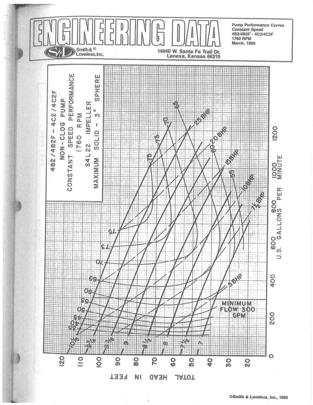
18 Table 2 Existing Thompson s Pump Station Summary Component Value Pumps (2) 7.5 HP Smith & Loveless, 4B2, 7 Imp. Current Pump Capacity ± 35 GPM Wet Well 6 Diameter, Concrete Wet Well Top Elevation 2,351.5 Wet Well SS In Elevation 2, Wet Well Bottom Elevation ± 2, Force Main High Point ± 2,361 Force Main Discharge Elevation ± 2,34 Force Main ± 2,9 LF of 6 Cast Iron Electrical Service 23 Volt, 3-Phase, 2 Amp Summary of Identified Deficiencies: Difficult access Aged and generally worn components Hazardous personal access Pumps subject to ragging and clogging Within 1-year flood zone No standby generator B. Future Requirements At this time no significant development in the Thompson s Pump Station service area is anticipated. Moreover, since Thompson s is upstream of miles of existing gravity collection system and two major pump stations, capacity upgrades could require significant and costly downstream infrastructure upgrades Should development be anticipated, a sewer shed master plan should be prepared to determine the probable extent of development, corresponding flows, and best method of providing sanitary sewer for such. As previously noted, the station suffers from a substantial amount of I/I. Similarly, increasing capacity to ensure conveyance of the substantial amount of extraneous I/I is not recommended, as such would also likely require significant and costly downstream infrastructure upgrades. Dollars would be better spent by the Sanitary Board to continue to locate and disconnect sources of I/I in the upstream collection system. Therefore, the evaluations presented below are based on a design pump rate of 35 GPM. Wastewater Pump Station Evaluation Page 14
19 Option 1 Complete Replacement This option would be for construction of a brand new pump station adjacent to the existing station. Due to age and original materials of construction, replacement of the existing force main is also recommended. In order to maintain functionality and minimize temporary piping, excessive road restoration costs, and provide for better maintenance conditions for Sanitary Board staff, the proposed replacement force main would not be installed in the same location as the existing. The probable location would be similar to the gravity sewer alignment presented in Option 2. Due to the site constraints and elevation in the flood plain, complete replacement will be difficult and leave the facility subject to substantial damage. While the existing 23V, 2 Amp, 3-phase electrical service is adequate for the existing and proposed equipment, a new service entrance is recommended due the age and condition of the existing main disconnect breaker and enclosure. Additionally, Variable Frequency Drives are recommended due to the substantial amount of I/I. Variable frequency drives can be used to reduce the pumping rate if necessary to prevent downstream capacity problems should they occur due slight increases in pump station discharge due to new, more efficient pumping equipment. Variable Frequency Drives can also substantially reduce the size of standby generators as they eliminate the initial starting load on the electrical system. Option 2 Eliminate Pump Station A somewhat odd feature of the Thompson s pump station is that it pumps down-hill. Further investigation determined that the station can be eliminated by installation of traditional gravity sewer. The station and force main was likely originally constructed in lieu of gravity sewer due to a lower initial installation cost. Option 2 would completely eliminate the Thompson s pump station. Installation of gravity sewer between Thompson s and the existing Brush Fork pump station would also allow additional customers to be served. D. Opinion of Cost and Recommendations The opinion of probable construction costs for each option presented above, as well as the anticipated operation and maintenance costs are summarized below in Table 3. Itemized and detailed opinion of probable construction and life cycle costs are contained as part of Appendix C. Table 3 Opinion of Probable Construction and Life Cycle Costs Item Cost Option 1 Complete Replacement $355,566 Option 1 Replace Force Main $196,164 Option 1 Total Initial Construction: $551,73 Option 1 2 Year O&M Costs $233,34 Option 1 Total 2 Year Cost $775,34 Option 2 Eliminate Pump Station $759,34 Wastewater Pump Station Evaluation Page 15
20 While the initial capital cost of eliminating Thompson s pump station is greater than replacement and upgrade, strong consideration should be given to complete elimination. Once normal, long term, Operation and Maintenance expenses are considered, the difference in anticipated overall life cycle costs are nearly identical. Additionally, elimination of a wastewater pump station eliminates the possibility of spills due to mechanical or electrical equipment failures. Installation of gravity sewer would allow immediate connections of 8 new customers, and additional line extensions to serve approximately 17 additional customers. Costs for line extensions are discussed in greater detail in Section V of this report. IV-2. Midway Pump Station A. Existing Conditions The Sanitary Board s Midway pump station was originally constructed in 1999 as part of the Brush Fork Sewer System Improvements project. The project also consisted of construction of the upstream Brush Fork pump station which served to eliminate an existing wastewater treatment lagoon, originally constructed and operated Bluewell Public Service District, but conveyed to the Sanitary Board of Bluefield. In 214, the pump station control panel was upgraded and a remote monitoring system was installed. The station is located on an easement adjacent to Ball Dairy Road. Midway receives flow from surrounding gravity sewer as well as the Brush Fork force main, which discharges directly to the station. The station location is shown on Sheet M-1 of Appendix D. The station is a triplex (three pump), submersible type station constructed of pre-cast concrete components and discharges through approximately 5,75 linear feet of 8 PVC force main. The Midway facility incorporates two inflow surge / equalization tanks; an on-site chemical feed tank and pump for odor control; and emergency standby generator. The pump station and force main were originally constructed by Sanitary Board staff. According to current staff, the actual force main contains portions of 6 PVC pipe. The force main was also installed at less than minimum required depth (36-inches req d). Additionally, no air release valves were installed during the original construction. At some point after the original construction, the force main was extended with 6 PVC to a manhole further downstream in order to resolve odor complaints from residents in the area of the original force main discharge location. The station has suffered from overflows since its original construction. In 21, Sanitary Board staff re-laid a portion of the force main and installed an air release valve in an attempt to increase station capacity and minimize overflows. After installation of the air release valve, Chapman Technical Group verified the pump and force main system was operating near its original design capacity. Wastewater Pump Station Evaluation Page 16


21 Actual calculations and field testing revealed the pumps showed some normal wear, but there were no apparent restrictions in the force main. Sanitary Board staff indicates that after installation of the air release valve the frequency of overflows was reduced; however, overflows still regularly occur. The overall pump station location is shown in Appendix A, on Sheet A-1, and Appendix D, on Sheet M-1. Additional station specifics are listed in Table 4, below. Photo 4 Existing Midway Wastewater Pump Station Generator & Control Panel Photo 5 Existing Midway Wastewater Pump Station Chemical Tank & Surge Tank Tops Photo 6 Existing Midway Wastewater Pump Station Valve Vault Piping Wastewater Pump Station Evaluation Page 17
22 Table 4 Existing Midway Pump Station Summary Component Value Pumps (3) 25 HP Flygt C Current Pumping Capacity 51 GPM Wet Well 18 x 8, Pre-Cast Concrete Wet Well Top Elevation 2,446.2 Wet Well SS In Elevation 2, Wet Well Bottom Elevation ± 2,431.8 Force Main High Point ± 2,522 Force Main ± 5,75 LF of 6 & 8 PVC Electrical Service 48 Volt, 3-Phase, 2 Amp Standby Generator Olympian 125 KVA Flow meters were installed in the upstream gravity sewer system by the Sanitary Board staff. Results were provided in excel format. A summary of such data is contained in Table 5, below. Table 5 Midway Pump Station Gravity Inflow Summary, GPM Function May July, 214 Aug Sept, 214 Average Min Max Standard Deviation 6 1 High Range Low Range Ranges calculated with one Standard Deviation from Average The flow meter data above represents only inflow from Midway s upstream gravity sewer. It does not include flow pumped directly to the station wet well by the Brush Fork pump station. The Brush Fork station adds an additional 38 GPM when pumping. Brush Fork run times indicate the station does not run continuously during large rain events. During the longest high flow period in the data set, the Brush Fork pump station operated 18.5 hours per day. 38 GPM x 18.5 hours per day/24 hours per day = 293 GPM Average Inflow It is reasonable to assume the Brush Fork pump station was designed with no less than a minimum peak flow factor of GPM / 2.5 = 152 GPM Average Design Flow Wastewater Pump Station Evaluation Page 18
23 Table 6 Midway Pump Station Total Inflow Summary, GPM Function Gravity Inflow Brush Fork Inflow Total Inflow Average Min Max ,272 Std. Dev. 1 N/A N/A High Range Low Range Ranges calculated with one Standard Deviation from Average At average and high range flows the Midway Pump Station has adequate pumping capacity to reliably convey flows without overflow, even when Brush Fork is operating. However, the station is overwhelmed during max flow, undoubtedly due to extraneous water from infiltration and inflow (I/I). Moreover, removing inflow from the Brush Fork pump station will not remedy the overall lack of station capacity. A major renovation of the Midway pump station would be required in order to reliably convey the total flow entering the station. The upgrade would include complete replacement of all pumps, piping, valves, generator, control panel, force main, and incoming electrical service upgrade. Moreover, since Midway is upstream of miles of existing gravity collection system increasing capacity to ensure conveyance of the substantial amount of extraneous I/I is not recommended, as such could require significant and costly downstream infrastructure upgrades. Dollars would be better spent by the Sanitary Board to continue to locate and disconnect sources of I/I in the upstream collection system. Therefore, the evaluations presented below are NOT based on a capacity upgrade. B. Future Requirements At this time no significant development in the Midway Pump Station service area is anticipated. Moreover, since Midway is upstream of miles of existing gravity collection system, capacity upgrades could require significant and costly downstream infrastructure upgrades. Should development be anticipated, a sewer shed master plan should be prepared to determine the probable extent of development, corresponding flows, and best method of providing sanitary sewer for such. However, there are approximately 3 unserved residences located nearby to the pump station, along Old Bramwell Road, that could easily be served by a gravity sewer extension from the existing collection system, and is shown on Sheet M-1 in Appendix D. 35 gallons per residence per day x 3 residences = 1,5 GPD 3 residences x 3 persons per residence = 9 people Peak Hourly Flow Factor = 18+ (9/1) = (9/1) 4.3 x 1,5 GPD / 24 hrs / 6 min = 31.4 GPM Req d Wastewater Pump Station Evaluation Page 19
24 Currently the Midway pump station does not have capacity to add additional customers; subsequently, it is recommended the additional line extension should NOT be completed until enough upstream I/I has been removed from the system to eliminate regular overflows. C. Upgrade Options As previously mentioned, a capacity upgrade is not recommended for the Midway pump station. Although the force main has been installed with less than required minimum cover and contains portions of 6 pipe rather than 8 as designed, it has not been particularly problematic. The pump station also has recently had two pumps and the control panel rebuilt. Remaining items that could require attention are minor and well within the capabilities of Sanitary Board staff. Recommended items include: Clean and repaint valve vault piping. Install dog house manhole on force main and relocate flow meter. Install pressure gauge taps on each pump discharge pipe, upstream of check valves. The Midway pump station is located on a Sanitary Board obtained easement. The conditions of the easement state the facility was to be constructed with a brick masonry building with a shingled roof, and maintain such in a manner fit for a residential neighborhood. The underlying property owner has frequently complained to the Sanitary Board that the building was never constructed. As such, an opinion of probable cost to enclose the generator, electrical equipment, chemical feed tank, and other above grade ancillary components within a brick masonry structure is provided below. Such building will offer little operation or maintenance advantages. It is also assumed the wet well, valve vault, and other precast structures will remain as-is. In order to safely construct a building where these features are enclosed will require replacement of the structures, or essentially a complete pump station replacement. The proposed electrical building would be similar to the one shown on Sheet EB1, in Appendix B. D. Opinion of Cost and Recommendations The opinion of probable construction cost presented below is for construction of an electrical building and removal of the existing fence at the station. Other recommended items that were identified are minor in capital cost and would likely be completed by in-house sanitary board staff. Costs for aforementioned line extensions are discussed in greater detail in Section V of this report. Table 7 Opinion of Probable Construction Cost Item Cost Construct Building & Remove Fence $141,114 Itemized and detailed opinion of probable construction costs are contained as part of Appendix D. Wastewater Pump Station Evaluation Page 2
25 IV-3. Brush Fork Pump Station A. Existing Conditions The Sanitary Board s Brush Fork pump station and force main was originally constructed by Sanitary Board staff in 1999 as part of the Brush Fork Sewer System Improvements project. The project eliminated an existing wastewater treatment lagoon, originally constructed and operated Bluewell Public Service District, but conveyed to the Sanitary Board of Bluefield. The station is located on an easement adjacent to Brush Fork Road. Brush Fork receives flow from the and Coppola Pump Stations. The station s location is shown on Sheet BF-1, in Appendix C. The station is a series-duplex (four pump) station where two submersible pumps discharge to two dry pit pumps. Each pair of series pumps operates independently of the other pair in a typical alternation/lead-lag scenario. All four pumps are identical 6 Horsepower Flygts, and are the largest in the Sanitary Board s system. The station pumps through approximately 6,732 linear feet of 8 PVC force main which ultimately discharges directly to the Midway pump station. The station is constructed of pre-cast concrete components and incorporates an onsite chemical feed tank and pump for odor control, and emergency standby generator. In 214, the pump station control panel was upgraded and a remote monitoring system was installed. Brush Fork does not normally suffer from overflows, even with the excessive amount of upstream I/I noted in the collection system upstream of Thompson s pump station. A review of pump run time data gathered from the recently installed remote monitoring system indicates that even during high flows the station cycles normally. Subsequently, it is believed the station has ample capacity. Although recent pump failures have occurred, such were attributed to poor workmanship on the part of the repair facility which previously rebuilt the pumps; no failures have resulted in overflows. Recent rebuilds have been performed by manufacturer authorized service facilities; it is therefore believed pumps are currently in good condition. The force main however has suffered from repeated failures. According to sanitary board staff, in many places the force main is laid on top of rock, shallow, or even exposed. Original design drawings indicate the force main was constructed with differing pipe pressure classes where heavier walled pipe was used leaving the pump station and in low areas where operating pressures were greater. This practice is generally not recommended as accidental placement of inadequate pressure class pipe is not uncommon and could be a contributing factor in force main failures. Brush Fork also suffers from a substantial amount of rags which are passed through the Thompson s pump station. Although Brush Fork normally passes rags without clogging, such rags and solids can cause problems with level controls which could ultimately lead to premature pump failures. Wastewater Pump Station Evaluation Page 21


26 Both options presented for the Thompson s pump station include installation of grinders which should substantially reduce the amount of rags and other debris entering the Brush Fork pump station. Photo 7 Brush Fork Wastewater Pump Station Hung Float Photo 8 Brush Fork Wastewater Pump Station - 6 HP Pump Photo 9 Brush Fork Wastewater Pump Station Rag Bound Float Wastewater Pump Station Evaluation Page 22
27 The pump station was originally constructed with an inadequately sized electrical service. The incoming electrical service, nor emergency generator, is capable of operating all four pumps concurrently. To prevent the second pair of pumps from starting upon a high water level and completely shutting down the station, the lag pump run feature has been disabled. While the station has not suffered overflows from such, a lead pump pair failure could result in an overflow condition if Sanitary Board staff were not in a position to immediately respond to alarm conditions. Additionally, redundancy is a requirement of the WV DEP NPDES permit. The existing electric service entrance also contains no over-current protection. Previously when, without knowledge of the inadequately sized electric service, operators tried to operate more than two pumps, the main utility-line fuses blew. Station specifics are presented in Table 8 below. Table 8 Existing Brush Fork Pump Station Summary Component Value Pumps (4) 6 HP Flygt CP(T) Current Pump Capacity 38 GPM Wet Well 12 Dia., Pre-Cast Concrete Wet Well Top Elevation* 2,345.5 Wet Well SS In Elevation* 2,34. Wet Well Bottom Elevation* 2,33.67 Force Main High Point* ± 2,662 Force Main Discharge Elevation* ± 2,438 Force Main 6,732 LF of 8 PVC Electrical Service 48 Volt, 3-Phase, 2 Amp Standby Generator Olympian 225 KVA * Elevations obtained from Record Drawings B. Future Requirements As previously noted, as with surrounding station service areas, at this time no significant development in the Brush Fork pump station service area is anticipated. Moreover, since Brush Fork is upstream of miles of existing gravity collection system and the Midway pump station, capacity upgrades could require significant and costly downstream infrastructure upgrades. Should development be anticipated, a sewer shed master plan should be prepared to determine the probable extent of development, corresponding flows, and best method of providing sanitary sewer for such. C. Upgrade Options As previously noted, the Brush Fork pump station currently has adequate capacity to convey current flows, including excessive upstream I/I. While excessive rag buildup is a problem, the installation of a grinder which has been presented for upgrade and elimination options at the Thompson s pump station should substantially alleviate the ragging problems at the Brush Fork station. Wastewater Pump Station Evaluation Page 23
28 Although the existing generator is not adequately sized to operate all four wastewater pumps, it is currently in good condition and replacement is not recommended. In lieu of a new and larger generator, it is recommended the pump control panel should be interlocked with the generator to limit station operation to only one pair of pumps while operating on generator power. Since the Brush Fork station has not historically suffered overflows with only one pair of pumps operable, utilization of the second and redundant pair would be required only during unusual high flow conditions; operating all four pumps during a utility power outage would represent an extremely rare occurrence. It is believed the cost to install a new and larger generator to protect against such extremely rare occurrences would outweigh the potential benefit which may never be utilized. D. Opinion of Cost and Recommendations The opinion of probable construction costs for each option presented above are summarized below in Table 3. Itemized and detailed opinion of probable construction costs are contained as part of Appendix E. Table 9 Opinion of Probable Construction Costs Item Cost Replace Force Main $33,2 Upgrade Electrical Service (AEP) $9,5 Pump Station Electrical Components $3,733 Total $343,235 At this point, it is recommended replacement of the entire length of force main should be planned and budgeted. The last approximately 3,3 linear feet of force main generally flows downhill, and by gravity. Therefore, this portion of the pipeline is not subject to significant operating pressures and regular surges and may be able to be reliably re-used. Such determination should be made during detailed design and construction document preparation however. Wastewater Pump Station Evaluation Page 24


29 IV-4. Copolla Pump Station A. Existing Conditions The Copolla pump station is located within eyesight of the Brush Fork pump station, to the west, in the Copolla Mobile Home Park. The Copolla station is a small grinder which serves the immediate surrounding mobile homes and a single, single family residence. The station s location is shown on Sheet BF-1 in Appendix C. The Copolla pump station was originally constructed as a private pump station to serve the mobile home park, but was conveyed to the Sanitary Board in 211. As such little specific information, beyond field observations, is available. The pump station is constructed of a 6-1 deep steel wet well with an integral valve vault. The pumps are single phase grinder type pumps believed to be manufactured by Goulds. At the time of field visit there was not adequate liquid in the wet well or inflow to perform a drawdown test. However, due to the limited area of the collection system, reasonable tributary flow volumes can accurately be calculated. There was no evidence in the station or surrounding areas of high wet well levels or sewer overflows. The Sanitary Board staff has reported the station has generally not been problematic. As expected, corrosion was noted on the steel components, but no deep pitting or complete loss of material was evident. A complete examination of the bottom or exterior of the wet well was not possible however. The existing control panel was generally in acceptable condition from a functionality standpoint; however it does not contain intrinsic safe barriers for control circuits which enter the wet well, as required by the National Electric Code (NEC). Photo 11 Copolla Wastewater Pump Station Photo 1 Copolla Wastewater Pump Station Control Panel Photo 12 Copolla Wastewater Pump Station Wet Well Wastewater Pump Station Evaluation Page 25
30 B. Future Requirements Due to the location of the pump station, the possibility of its utilization to receive additional wastewater flows are limited. There are currently approximately 12 additional un-sewered customers which could be served by the pump station. Current Estimated Flow: Assume 2 persons per residence for mobile homes, or 2/3 of normal residential values: 35 x 2/3 = 233 Gallons per residence per day 233 gallons per residence per day x 69 residences = 16,77 GPD 69 residences x 2 persons per residence = 138 people Peak Hourly Flow Factor = 18+ (138/1) = (138/1) 4.2 x 16,77 GPD / 24 hrs / 6 min = 47 GPM Additional Estimated Flow: 35 gallons per residence per day x 12 residences = 4,2 GPD 4.2 x 4,2 GPD / 24 hrs / 6 min = 12 GPM Req d Total Estimated Flow: 47 GPM + 12 GPM = 59 GPM Req d C. Upgrade Options Although the station is not currently suffering from capacity or reliability issues, due to its age and steel construction, ultimate replacement should be considered and budgeted for in the foreseeable future. Fortunately, due to the station s small size, such is within the capabilities of the Sanitary Board staff. Although the exact capacity of the station is unknown at this time, similarly due to its small size, there would be negligible cost difference between replacement components sized to convey current tributary flows as possible future flows. Wastewater Pump Station Evaluation Page 26
31 The primary consideration with respect to upgrade of the Copolla pump station is, due to its location relative to Brush Fork, would be to eliminate the pump station completely. Since the Copolla pump station is constructed at a lower elevation than the Brush Fork pump station, it is not possible to construct gravity sewer to convey flow to the existing Brush Fork pump station; however, it is possible to construct a single station to eliminate both existing stations. Constructing a new station utilizing all new components would similarly be cost prohibitive; however, as previously noted, the existing Brush Fork pump station contains recently rebuilt pumps, a rebuilt control panel, and a generator in good condition. Such components could be moved and installed in a new wet well and valve vault. D. Opinion of Cost and Recommendations Opinions of probable construction cost for complete replacement of the Copolla pump station as well as the necessary work to relocate Brush Fork and eliminate the Copolla pump station are contained below in Table 1. Detailed opinion of probable construction costs are contained in Appendix F. Due to the small size of the Copolla pump station, it is anticipated replacement would be completed utilizing in-house staff; costs shown are shown for parts and equipment only. Table 1 Opinion of Probable Construction Costs Item Cost Option 1 Replace Copolla Pump Station $35, Option 1 2 Year O&M Costs $74,7 Option 1 Total 2 Year Cost $19,7 Option 2 Relocate Brush Fork Pump Station $489,927 Relocation of the Brush Fork facility has the added benefit of utilizing all new piping and concrete which, although currently in good condition at Brush Fork, do have a finite life and will at some point beyond a reasonable planning period require replacement or rehabilitation. However, even when the long term cost of ownership associated with the Copolla pump station is considered, it is still more economical to replace it in at its current location. Although there also many intrinsic benefits in elimination of any pump station, it is not believed the cost to do so is worth the benefit. Wastewater Pump Station Evaluation Page 27
32 V. Line Extensions and Additional Customers As previously referenced, there are two opportunities to relatively easily add several additional customers while contractors are mobilized in the area and the Sanitary Board is seeking capital for system improvements. Opinions of probable construction cost and a description of each are presented below. A. Thompson s Gravity Extensions The first opportunity to add additional customers would be a separate line extension along Nichols Road from the proposed gravity sewer main which eliminates the Thompson s pump station. Such extensions are shown on Sheet TG-2, contained in Appendix C, and are identified as Thompson Gravity Extension Line B and Thompson Gravity Extension Line C. These costs are for only customers who would be added due to additional line extensions; customers added to as a result of the main line installation required to eliminate the pump station are not considered in the analysis presented below. A detailed opinion of probable construction cost and basic financial analysis is provided in Appendix G. Table 11 Opinion of Probable Construction Costs & Analysis Item Cost Thompson s Gravity Extensions $448,823 Annualized Debt Service (4% Interest) $25,713 Anticipated Revenue (Average Bill, Current Tariff) $7,98 Net $-17,733 B. Midway Gravity Extension The second opportunity to add additional customers is a new line extension from the existing gravity collection system upstream of the Midway pump station, along Old Bramwell Road. The extensions are shown on Sheets M-2 and M-3, contained in Appendix D, and are identified as Thompson Gravity Extension Line B and Thompson Gravity Extension Line C. A detailed opinion of probable construction cost and basic financial analysis is provided in Appendix G. Table 12 Opinion of Probable Construction Costs & Analysis Item Cost Midway Gravity Extensions $654,282 Annualized Debt Service (4% Interest) $37,484 Anticipated Revenue (Average Bill, Current Tariff) $11,76 Net $-25,724 Wastewater Pump Station Evaluation Page 28
33 C. Results As indicated above, based solely on projected additional revenue, it is not financially feasible to extend service to the areas in question by conventional gravity sewer. If connecting the additional customers is desired, alternative technologies such as Septic Tank Effluent Pump / Gravity (STEP or STEG) or low pressure grinder pump systems may provide a more economically viable option. However, such systems do require regular maintenance thus a complete life cycle analysis should be taken into consideration. VI. Summary, Recommendations, and Implementation A. Summary Various alternatives have been presented with their associated opinion of probable construction costs. Table 13 below summarizes the various options and their associated anticipated capital costs. Items labeled as Options are just that various ways to provide the necessary level of continued service. The Optional items are not required to provide continued, reliable sewer service; however such additional items may be determined as appropriate for the specific installations. Table 13 Opinion of Probable Construction Costs Item Cost Deerfield Wastewater Pump Station Options Option 1 Rehabilitate Existing $27,562 Option 2 PS Upgrade (Phase I) $43,34 Option 2 Force Main Upgrade (Phase II) $14,647 Optional Electrical Building (Inc. deducts for site-items not required) $7,28 Thompson s Wastewater Pump Station Options Option 1 Complete Station & Force Main Replacement $551,73 Option 2 - Elimination / Gravity Sewer Installation $759,34 Midway Wastewater Pump Station Optional Electrical Building & Site Rehabilitation $141,114 Brush Fork Wastewater Pump Station Brush Fork Force Main & Electrical Upgrade $343,235 Copolla Wastewater Pump Station Option 1 Replace Pump Station $35, Option 2 Eliminate Pump Station (Replace Brush Fork) $489,927 Wastewater Pump Station Evaluation Page 29
34 While the ultimate decision as two which combination of options best suites the Sanitary Board s long term goals rests with the Board Members, a probable proposed project scenario is detailed below. B. Probable Project Scenario The Deerfield wastewater pump station will be replaced with a new station which would allow extensions of service to nearby residences. It is anticipated the larger force main will be constructed at a later date if local growth necessitates. At this time it is anticipated the optional electrical building will not be constructed. Thompson s pump station will be eliminated by the installation of new gravity sewer. While installation of new sewer does carry a higher initial capital cost, it is the less expensive alternative when basic operation and maintenance expenses are considered. Additionally the gravity sewer extension will reduce the chance of spills as a result of equipment failures and generate revenue from additional customers, which was not accounted for in life cycle analysis. It is recommended in lieu of constructing a new building and performing site modifications to comply with the original conditions of the easement, an alternative agreement should be negotiated with the underlying property owner. Such would likely be substantially less costly. The Brush Fork pump station will remain in its current location and configuration but will be connected to a new, properly constructed, downstream force main. At this time no action is recommended at the Copolla pump station. Ultimately a complete replacement of the station will be required; however package type complete pump stations are available and well suited for this installation. Similarly, due to the small size and relatively simple installation requirements, such replacement can be performed by Sanitary Board staff as part of normal R & R operations. As such, the associated costs are not included in the probable project costs presented below. Table 14 Opinion of Probable Construction Costs Minimum Recommended Item Cost Deerfield Upgrade (Phase I) $43,34 Thompson s Elimination / Gravity Sewer Installation $759,34 Brush Fork Force Main & Electrical Upgrade $343,235 Total Opinion of Probable Construction Cost $1,55,69 Wastewater Pump Station Evaluation Page 3
35 C. Recommendations The opinion of probable construction cost presented above represents only the necessary improvements to the pump stations and associated force mains. As noted previously, additional repairs to the collection system are warranted to economically resolve capacity issues at Thompson s and Midway pump stations. The Sanitary Board has retained The Thrasher Group to provide SSES services to determine specific areas of the collection system which require rehabilitation or replacement to reduce the extraneous I/I which is directly responsible for capacity issues at these two facilities. It is anticipated and recommended that if financing is sought from state agencies, such as West Virginia Department of Environmental Protection, a single application and bond issue for both collection system and pump station facilities should be made as many soft costs are fixed; and multiple applications and bond issues would result in unnecessary expenses. Since at this time the SSES study is not yet completed, the total required project budget and time frame to obtain funding, design improvements, and complete construction is unknown. Given the aforementioned DEP Administrative Order, it is recommended that while the SSES is being completed, the Sanitary Board proceed with necessary property acquisition at Deerfield, and preparation of construction documents for the selected alternatives presented herein. Once recommendations from the SSES have been received, construction document preparation for collection system rehabilitation and overall project funding applications can be begin. Wastewater Pump Station Evaluation Page 31
36 Appendix A Overall Pump Station Location Map

37 AIRPORT PLANNING / DEVELOPMENT ARCHITECTURE / INTERIOR DESIGN CIVIL ENGINEERING / SITE DEVELOPMENT ENVIRONMENTAL ENGINEERING LANDSCAPE ARCHITECTURE St. Albans, WV (34) Buckhannon, WV (34) Martinsburg, WV (34) a division of SURVEYING
38 Appendix B Deerfield Pump Station Exhibits DF-1: Overall Service Areas DF-2: Possible Future Service Areas DF-3: Proposed Site Plan DF-4: Force Main Profile EB1: Electrical Building Details 11 HP Pump Data Sheet 23 HP Pump Data Sheet Flow Case 1 Wet Well Calculations Flow Case 2 Wet Well Calculations Opinion of Probable Construction Costs

39 AIRPORT PLANNING / DEVELOPMENT ARCHITECTURE / INTERIOR DESIGN CIVIL ENGINEERING / SITE DEVELOPMENT ENVIRONMENTAL ENGINEERING LANDSCAPE ARCHITECTURE St. Albans, WV (34) Buckhannon, WV (34) Martinsburg, WV (34) a division of SURVEYING
40 Opinion of Probable Construction Cost Deerfield Pump Station Option 1 Rehabilitate Existing Description Quan. Unit Unit Price Total Price Submersible Grinder Pumps 2 EA $16,564.5 $33,129. Pump Control Panel 1 EA $32,21.75 $32,21.75 Remote Monitoring System 1 LS $6,21. $6,21. Replace Threaded Valves & Check Valves 1 LS $2,27. $2,27. Control Panel Backboard 1 LS $3,357. $3,357. Flow Meter 1 EA $5,113. $5,113. Flow Meter Manhole 1 EA $2,5. $2, kw 1-Phase Generator w/ Tank & ATS 1 LS $61,91. $61,91. Lighting - Site 1 LS $2,558. $2,558. Electrical Misc. Materials & Installation 1 LS $14,33. $14,33. Fencing 1 LS $8,. $8,. Access Road Construction - Earthwork 3 CY $3. $9,. Access Road & Site Stone 8 CY $4. $3,2. Bypass Connection Standpipe 1 LS $6,82. $6,82. Bypass Pumping (2 pumps plus fuel) 14 Day $6. $8,4. Yard Hydrant & Water Service 1 LS $3,852.5 $3,852.5 Mobilization/Insurance/Gen. Conditions (3%) 1 LS $5, $5, Total Opinion of Probable Construction Cost $27,562
41 Opnion of Probable Construction Cost Deerfield Pump Station Option 2 Replace & Upgrade Description Quan. Unit Unit Price Total Price Submersible Pumps w/ Bases & Guide Rails - 23 HP 2 EA $26,512. $53,24. Pump Control Panel 1 EA $33,562. $33,562. Variable Frequency Drives 2 EA $7,351. $14,72. Remote Monitoring System 1 LS $6,21. $6,21. Chanel Grinder 1 EA $5,264. $5,264. Grinder Control Panel 1 EA $1,12. $1,12. Grinder Vault 1 EA $6,. $6,. 8' Diameter Wet Well 1 EA $16,764. $16,764. Valve Vault 1 EA $2,5. $2,5. FL DI Valves & Piping 1 LS $14,91. $14,91. Ballast Concrete 1 CY $1,5. $15,. Flow Meter 1 EA $5,113. $5,113. Flow Meter Manhole 1 EA $2,5. $2, kw 1-Phase Generator w/ Tank & ATS 1 LS $61,91. $61,91. Control Panel Backboard 1 LS $3,357. $3,357. Lighting - Site 1 LS $2,558. $2,558. Electrical Misc Materials & Installation 1 LS $14,33. $14,33. Fencing 1 LS $8,. $8,. Access Hatches 3 EA $4,674. $14,22. Painting & Coatings 1 LS $9,83. $9,83. Site Excavation & Material Waste 225 CY $25. $5,625. Site Final Grading 1 LS $5,264. $5,264. Access Road Construction - Earthwork 3 CY $3. $9,. Access Road & Site Stone 8 CY $4. $3,2. Doghouse Manhole 1 EA $4,5. $4,5. 8" Gravity Sewer Piping 5 LF $75. $3,75. Air Release Valve & Vault 1 LS $6,. $6,. AEP Electric Service Upgrade 1 LS $4,. $4,. Startup / Reliability Testing 1 LS $2,4. $2,4. Yard Hydrant & Water Service 1 LS $3,852.5 $3,852.5 Mobilization/Insurance/Gen. Conditions (3%) 1 LS $11, $11, Total Opinion of Probable Construction Cost $43,34
42 Opinion of Probable Construction Cost Deerfield Pump Station Force Main Replacement Description Quan. Unit Unit Price Total Price 6" C-9 PVC Force Main 2,285 L.F. $3. $68,55. Asphalt Restoration 1,3 L.F. $4. $52,. 12" Steel Casing Pipe - Bore & Jack Installation 5 L.F. $25. $12,5. Connect to Existing MH 1 L.S. $3,5. $3,5. Mobilization/Insurance/Gen. Conditions (3%) 1 L.S. $4,96.5 $4,96.5 Total Opinion of Probable Construction Cost $14,647
43 Opnion of Probable Construction Cost Deerfield Pump Station Electrical Building Description Quan. Unit Unit Price Total Price Brick Masonry Building, 2' x 14' 28 SF $2. $56,. Louvers/Dampers - Large (Generator) 2 EA $2,. $4,. Louvers - Small 1 EA $1,. $1,. Exhaust Fan 1 EA $1,5. $1,5. Lighting - Interior & Exterior 1 LS $8,147. $8,147. Electric Unit Heater 1 EA $1,678.5 $1,678.5 Exterior Generator Fueling Connection 1 EA $4,57. $4,57. Generator Piping & Duct Work 1 LS $1,71. $1,71. Less Exterior Generator Enclosure (1) LS $5,. ($5,.) Less Site Fence (1) LS $8,. ($8,.) Less Control Panel Backboard (1) LS $3,357. ($3,357.) Less Lighting - Site (1) LS $2,558. ($2,558.) Mobilization/Insurance/Gen. Conditions (3%) 1 LS $2,39.66 $2,39.66 Total Opinion of Probable Construction Cost $7,28

44 AIRPORT PLANNING / DEVELOPMENT ARCHITECTURE / INTERIOR DESIGN CIVIL ENGINEERING / SITE DEVELOPMENT ENVIRONMENTAL ENGINEERING LANDSCAPE ARCHITECTURE St. Albans, WV (34) Buckhannon, WV (34) Martinsburg, WV (34) a division of SURVEYING
45 AIRPORT PLANNING / DEVELOPMENT ARCHITECTURE / INTERIOR DESIGN CIVIL ENGINEERING / SITE DEVELOPMENT ENVIRONMENTAL ENGINEERING LANDSCAPE ARCHITECTURE St. Albans, WV (34) Buckhannon, WV (34) Martinsburg, WV (34) a division of SURVEYING
46 AIRPORT PLANNING / DEVELOPMENT ARCHITECTURE / INTERIOR DESIGN CIVIL ENGINEERING / SITE DEVELOPMENT ENVIRONMENTAL ENGINEERING LANDSCAPE ARCHITECTURE St. Albans, WV (34) Buckhannon, WV (34) Martinsburg, WV (34) a division of SURVEYING
47 X X X X X X AIRPORT PLANNING / DEVELOPMENT ARCHITECTURE / INTERIOR DESIGN CIVIL ENGINEERING / SITE DEVELOPMENT ENVIRONMENTAL ENGINEERING LANDSCAPE ARCHITECTURE St. Albans, WV (34) Buckhannon, WV (34) Martinsburg, WV (34) SURVEYING
48 Denom inat ion Dr awn by Sc ale Chec k ed by Dat e Reg no NP 3127 SH 3~ Adaptive 249 Te chnical specification [f t] Head 61.5% mm [US g.p.m.] Water, pure Curve according to: ISO 996 grade 2 annex 1 or 2 Note: Picture might not correspond to the current configuration. General Patented self cleaning semi-open channel impeller, ideal f or pumping in waste water applications. Possible to be upgraded with Guide-pin f or ev en better clogging resistance. Modular based design with high adaptation grade. Impeller Impeller material Grey cast iron Discharge Flange Diameter 3 1/8 inch Suction Flange Diameter 8 mm Impeller diameter 146 mm Number of blades 2 Installation: P - Semi permanent, Wet 38 1/2 (TO FURTHEST POINT) REF.LINE 28 3/8 83/8 87/8 63/4 2 33/8 16 3/4 REF.LINE 19" 11/8 93/8 49/16 2" GUIDE BARS Ø3" 2 1/2 7 1/8 6 1/8 6 3/8 Motor Motor # N AL-W 11hp Stator v ariant 28 Frequency 6 Hz Rated v oltage 2 V Number of poles 2 Phases 3~ Rated power 11 hp Rated current 29 A Starting current 256 A Rated speed /min Power f actor 1/1 Load.92 3/4 Load.9 1/2 Load.85 Ef f iciency 1/1 Load 3/4 Load 1/2 Load 87.7 % 88.4 % 87.7 % 15 3/4 *1 5/8 2" Z Z 23/4 3 3/8 24 1/4 11" MIN LEVEL Configuration 2 3/8 REF.LINE VIEW Z - Z 4" 8" CL OF DISCH 97/8 BOLT Ø 3/4 (4x) Weight (lbs) * DIMENSION TO ENDS OF GUIDE BARS AUTOCAD DRAWING Dimensional drwg FP, NP 3127 SH Ø3 " NK Pump Disch RB Project Project ID Created by Created on Last update
![BoltØ 3/4(4X) Denom inat ion Dr awn by Sc ale by Chec k ed Dat e Reg no NP 3153 SH 3~ 274 Te chnical specification [f t] 23 22 21 2 19 18 17 16 15 14 13 12 11 1 9 8 7 6 5 4-3 2 1 Head 6.](/docs-images/75/72405157/images/49-0.jpg "9% 274 176mm 1 2 3 4 5 6 7 [US g.p.m.] Water, pure Curve according to: ISO 996 grade 2 annex 1 or 2 Note: Picture might not correspond to the current configuration.")
49 BoltØ 3/4(4X) Denom inat ion Dr awn by Sc ale by Chec k ed Dat e Reg no NP 3153 SH 3~ 274 Te chnical specification [f t] Head 6.9% mm [US g.p.m.] Water, pure Curve according to: ISO 996 grade 2 annex 1 or 2 Note: Picture might not correspond to the current configuration. General Patented self cleaning semi-open channel impeller, ideal f or pumping in waste water applications. Possible to be upgraded with Guide-pin f or ev en better clogging resistance. Modular based design with high adaptation grade. Impeller Impeller material Grey cast iron Discharge Flange Diameter 3 1/8 inch Suction Flange Diameter 8 mm Impeller diameter 176 mm Number of blades 2 Installation: P - Semi permanent, Wet 38" Ref.Line 27 3/4 51/2 67/8 45Â Ref.Line 2 7/8 33/8 17 1/2 2" Guide bars 49/16 93/8 Ø3" ( To Furthest Point) 5 1/2 34 1/2 6 7/8 6 7/8 Motor Motor # N BB-W 23hp Stator v ariant 8 Frequency 6 Hz Rated v oltage 2 V Number of poles 2 Phases 3~ Rated power 23 hp Rated current 59 A Starting current 46 A Rated speed 355 1/min Power f actor 1/1 Load.92 3/4 Load.89 1/2 Load.82 Ef f iciency 1/1 Load 3/4 Load 1/2 Load 9.5 % 91.5 % 91.5 % 15 3/4 1 1/4* Min.Level 11" Configuration 2 3/8 Z 2 3/4 Z 3 1/2 8" 4" 2 1/2 Ref.Line CL of discharg 9 7/8 Z-Z AUTOCAD DRAWING * DIMENSION TO ENDS OF GUIDE BARS Weight (lbs) Pump Disch Dimensional drwg NP,FP 3153 SH Ø3 " NK Project Project ID Created by Created on Last update
50 Bluefield Sanitary Board Deerfield Pump Station Wet Well Calculations Flow Case 1 Total ADF Ave. Day Flow (gpd) 69,3 69,3 GPD Initial Average Daily Flow = 69,3 GPD GPM Peaking Factor = 3.9 Peak Flow = 27,27 GPD Peak Flow = GPM Design Peak Flow = 2 GPM Force Main Diameter = 4. Inches 4ʺ Velocity = 5.1 FPS
51 Bluefield Sanitary Board Deerfield Pump Station Wet Well Calculations Flow Case 1 Determine Active Storage Volume in Pump Station Q ddf = 48 gpm Q = 2 gpm Size Wetwell Wetwell Wetwell Wetwell Wetwell Diameter Area Cycle Volume (feet) (gal / VF) (ft) (gal) Check Wetwell Cycles Fill = Wetwell Volume = 15.6 minutes Q ddf Run = Wetwell Volume = 4.9 minutes Q Q ddf Total = 2.6 minutes Cycle Time = 2.9 Cycles / Hour Top Elev= Gnd Elev= ʹ ID Wetwell Inv In = Alarm = Lag On = Lead On = 242. L.L. Off = Bott. EL = 2416.
52 Bluefield Sanitary Board Deerfield Pump Station Wet Well Calculations Flow Case 2 Total ADF Ave. Day Flow (gpd) 164, ,571 GPD Initial Average Daily Flow = 164,571 GPD GPM Peaking Factor = 3.5 Peak Flow = 575,999 GPD Peak Flow = 4. GPM Design Peak Flow = 4 GPM Force Main Diameter = 6. Inches 6ʺ Velocity = 4.5 FPS
53 Bluefield Sanitary Board Deerfield Pump Station Wet Well Calculations Flow Case 2 Determine Active Storage Volume in Pump Station Q ddf = 114 gpm Q = 4 gpm Size Wetwell Wetwell Wetwell Wetwell Wetwell Diameter Area Cycle Volume (feet) (gal / VF) (ft) (gal) Check Wetwell Cycles Fill = Wetwell Volume = 13.2 minutes Q ddf Run = Wetwell Volume = 5.3 minutes Q Q ddf Total = 18.4 minutes Cycle Time = 3.3 Cycles / Hour Top Elev= Gnd Elev= ʹ ID Wetwell Inv In = Alarm = Lag On = Lead On = 242. L.L. Off = Bott. EL = 2414.
54 Appendix C Thompson s Pump Station Exhibits BF-1: Overall Service Areas Existing Pump Curve Calculated Pump & System Curve Proposed 7.5 HP Pump Data Sheet Station Run Times October 214 T-1: Proposed Site Plan TG-1: Proposed Gravity Alignment TG-2: Proposed Gravity Alignment TG-P: Gravity Sewer Ground Profiles Opinion of Probable Construction Costs

55 AIRPORT PLANNING / DEVELOPMENT ARCHITECTURE / INTERIOR DESIGN CIVIL ENGINEERING / SITE DEVELOPMENT ENVIRONMENTAL ENGINEERING LANDSCAPE ARCHITECTURE St. Albans, WV (34) Buckhannon, WV (34) Martinsburg, WV (34) a division of SURVEYING
56 Opnion of Probable Construction Cost Thompson's Pump Station Option 1 Complete Replacement Description Quan. Unit Unit Price Total Price Submersible Pumps w/ Bases & Guide Rails HP 2 EA $16,564.5 $33,129. Pump Control Panel 1 EA $32,21.75 $32,21.75 Variable Frequency Drives 2 EA $5,51. $1,12. Salvage & Reinstall Remote Monitoring System 1 LS $2,176. $2,176. Chanel Grinder 1 EA $5,264. $5,264. Grinder Control Panel 1 EA $1,12. $1,12. Grinder Vault 1 EA $6,. $6,. 8' Diameter Wet Well 1 EA $16,764. $16,764. Valve Vault 1 EA $2,5. $2,5. FL DI Valves & Piping 1 LS $14,91. $14,91. Ballast Concrete 1 CY $1,5. $15,. Flow Meter 1 EA $5,113. $5,113. Flow Meter Manhole 1 EA $2,5. $2,5. 35 kw 3-Phase Generator w/ Tank & ATS 1 LS $38,91. $38,91. Control Panel Backboard 1 LS $3,357. $3,357. Lighting - Site 1 LS $2,558. $2,558. Electrical Misc Materials & Installation 1 LS $14,33. $14,33. Fencing 1 LS $8,. $8,. Access Hatches 3 EA $4,674. $14,22. Painting & Coatings 1 LS $9,83. $9,83. Site Excavation & Material Waste 225 CY $25. $5,625. Site Final Grading 1 LS $5,264. $5,264. Sheeting & Trench Support 1 LS $1,. $1,. Site Stone 3 CY $4. $1,2. Doghouse Manhole 1 EA $4,5. $4,5. 8" Gravity Sewer Piping 5 LF $75. $3,75. Bypass Pumping 21 Day $7. $14,7. AEP Electric Service Upgrade 1 LS $2,5. $2,5. Startup / Reliability Testing 1 LS $2,4. $2,4. Yard Hydrant & Water Service 1 LS $3,852.5 $3,852.5 Mobilization/Insurance/Gen. Conditions (3%) 1 LS $1, $1, Total Opinion of Probable Construction Cost $355,566

57 Opinion of Probable Construction Cost Thompson's Pump Station Option 1 Force Main Replacement Description Quan. Unit Unit Price Total Price 6" C-9 PVC Force Main 3,95 L.F. $3. $92,85. Asphalt Restoration 15 L.F. $4. $6,. Stone Surface Restoration 65 L.F. $5. $3,25. 12" Steel Casing - Bore & Jack 13 L.F. $25. $32,5. 12" Steel Casing - Bore & Jack Stream Crossing 1 L.F. $3. $3,. Air Release Valve & Vault 3 EA $6,. $18,. Abandon-in-place existing FM 2,9 L.F. $1.5 $4,35. Connect to Existing MH 1 L.S. $3,5. $3,5. Mobilization/Insurance/Gen. Conditions (3%) 1 L.S. $5,713.5 $5,713.5 Total Opinion of Probable Construction Cost $196,164
58 Thompson s Pump Station Option 1 Replacement Probable Operation & Maintenance Costs Assumptions: 2 year planning period Current electrical power rate of $.7/kW hr remains constant Pump operation of 8 hours per day (assumes reduction in upstream I/I) 1 year pump and control panel life 2 year generator life 8hrs x 365 days = 2,92 hours per year Pump HP: 7.5 Pump Motor FLA: VAC Actual Pumping HP Req d (Reference Pump Curve): 7.6 HP Actual Electrical Power Approximation: 22 Amps x 7.6/7.5 = 2.7 Amps 2.7 Amps x 23 Volts x 3 / 1 = 8.2 kw 8.2 kw x 2,92 hours/year x $.7/kW hr = $1,676 / year $1,676/year x 2 years = $33,52 Replacement Pumps: 2 x $33,129 = $66,258 Replacement Control Panel & VFD s: 2 x ($32,211 + $1,12) = $84,626 Replacement Generator & ATS: $38,9 Total 2 year life cycle cost: $223,34
59 Opinion of Probable Construction Cost Thompson's Pump Station Option 2 Elimination Description Quan. Unit Unit Price Total Price 1" Gravity Sewer Pipe (< 6' Deep) 1,397 L.F. $13. $181,61. 1" Gravity Sewer Pipe (6' to 1' Deep) 955 L.F. $15. $143,25. 1" Gravity Sewer Pipe (> 1' Deep) 65 L.F. $175. $113,75. 2" Steel Casing - Bore & Jack 13 L.F. $25. $32,5. 2" Steel Casing - Bore & Jack Stream Crossing 1 L.F. $3. $3,. Precast MH (< 6' Deep) 8 EA $3,. $24,. Precast MH ( 6' to 1' Deep) 6 EA $4,. $24,. Precast MH ( > 1' Deep) 4 EA $4,5. $18,. Doghouse Manhole 1 EA $5,. $5,. Cleanout - House Service 8 EA $6. $4,8. Service Wye 8 EA $6. $4,8. 4" PVC Service Pipe 8 L.F. $6. $48,. Chanel Brush Fork PS 1 EA $5,264. $5,264. Grinder Control Brush Fork PS 1 EA $1,12. $1,12. Grinder Brush Fork PS 1 EA $6,. $6,. Asphalt Restoration 15 L.F. $55. $8,25. Stone Surface Restoration 65 L.F. $15. $9,75. Abandon Existing PS 1 LS $15,. $15,. Abandon-in-place existing FM 2,9 L.F. $1.5 $4,35. Connect to Existing MH 1 L.S. $3,5. $3,5. Mobilization/Insurance/Gen. Conditions (3%) 1 L.S. $22,17.78 $22,17.78 Total Opinion of Probable Construction Cost $759,34
60
61 Bluefield Sanitary Board Thompson's Pump Station WET WELL LIQUID LEVEL 2348 High Water Level FM HIGH POINT 234 STATIC HEAD -8 STATION LOSS 1 ENTER PIPE LENGTH 29 ENTER "C" VALUE 11 ENTER PIPE DIA. 6 FLOW SYS. HEAD 1 PUMP 2 PUMPS VELOCITY, fps Bluefield Sanitary Board Thompson's Pump Station S&L 4B2, 7-inch Impeller HEAD (FEET) SYS. HEAD 1 PUMP 2 PUMPS FLOW (GPM) 11/28/214 Exist System Curve xls
![Denom inat ion Dr awn by Sc ale by Chec k ed Dat e Reg no NP 3127 HT 3~ 489 Te chnical specification [f t] Head 68 64 6 56 52 48 44 4 36 66.6% 32 28 24 2 16 12-8 4 489 195mm 2 4 6 8 [US g.p.m.] Water, pure Curve according to: ISO 996 grade 2 annex 1 or 2 Note: Picture might not correspond to the current configuration.](/docs-images/75/72405157/images/62-0.jpg "General Patented self cleaning semi-open channel impeller, ideal f or pumping in waste water applications. Possible to be upgraded with Guide-pin f or ev en better clogging resistance.")
62 Denom inat ion Dr awn by Sc ale by Chec k ed Dat e Reg no NP 3127 HT 3~ 489 Te chnical specification [f t] Head % mm [US g.p.m.] Water, pure Curve according to: ISO 996 grade 2 annex 1 or 2 Note: Picture might not correspond to the current configuration. General Patented self cleaning semi-open channel impeller, ideal f or pumping in waste water applications. Possible to be upgraded with Guide-pin f or ev en better clogging resistance. Modular based design with high adaptation grade. Impeller Impeller material Grey cast iron Discharge Flange Diameter 3 15/16 inch Suction Flange Diameter 1 mm Impeller diameter 195 mm Number of blades 2 Installation: P - Semi permanent, Wet 39 1/4 REF.LINE 28 3/8 7" 5Â 8 3/8 33/8 16 3/4 REF.LINE 19" 11/8 93/4 49/16 2" GUIDE BARS (TO FURTHEST POINT) 6 3/4 9 1/8 7 3/4 Motor Motor # N AL-W 7.5hp Stator v ariant 28 Frequency 6 Hz Rated v oltage 2 V Number of poles 4 Phases 3~ Rated power 7.5 hp Rated current 22 A Starting current 128 A Rated speed 174 1/min Power f actor 1/1 Load.88 3/4 Load.85 1/2 Load.78 Ef f iciency 1/1 Load 3/4 Load 1/2 Load 82.5 % 84. % 83. % Ø4" 25" MIN LEVEL Configuration 15 3/4 *1 1/4 2" 12" Z 2 3/4 Z 3 1/8 2 3/4 REF.LINE VIEW Z Z 4" 8" CL OF DISCH 97/8 BOLT Ø 3/4 (4x) Weight (lbs) EQUIPPED WITH IMPELLER Pump Disch * DIMENSION TO ENDS OF GUIDE BARS AUTOCAD DRAWING Dimensional drwg FP, NP 3127 HT Ø4 " NK Project Project ID Created by Created on Last update
63 - Pump Calculations for The Sanitary Board of Bluefield - Wednesday, October 1, 214 to Friday, October 31, Pump Calculations - Device Num Station Pump Cycles AVG Draw Down Runtime Date: 11/1/ :8:13 13:59: :9:57 15:35:43 3 :: :: AVG GPM Station: Effluent Date: 1/31/ :1:7 4:16: :1:26 5:27:24 3 :: :: Station: Date: 1/3/ :1:9 7:8: :1:28 9:4:2 3 :: :: Station: Date: 1/29/ :1:6 2:13: :1:23 2:47:5 3 :: :: Station: Date: 1/28/ :1:2 2:12: :1:19 2:44:12 3 :: :: Station: Date: 1/27/ :1:6 4:14: :1:24 5:22:33 3 :: :: Station: Date: 1/26/ :1:9 4:15: :1:28 5:25:39 3 :: :: Station:
64 Date: 1/25/ :1:9 4:28: :1:31 5:49:32 3 :: :: Station: Date: 1/24/ :1:41 4:38: :2:4 5:41:1 3 :: :: Station: Date: 1/23/ :1:11 4:35: :1:34 6::5 3 :: :: Station: Date: 1/22/ :1:15 5:: :1:4 6:53:29 3 :: :: Station: Date: 1/21/ :1:16 5:6: 2 24 :1:45 7:2:5 3 :: :: Station: Date: 1/2/ :1:21 5:26: :1:54 7:41:5 3 :: :: Station: Date: 1/19/ :1:38 6:2: :2:29 9:13:5 3 :: :: Station: Date: 1/18/ :1:5 6:3: :3:11 1:26:34 3 :: :: Station:
65 Date: 1/17/ :7:13 6:52: :17:7 15:24:41 3 :: :: Station: Date: 1/16/214 1 :: 23:57:42 2 :: 18:51:34 3 :: :: Station: Date: 1/15/ :13:29 12:13: :13:34 12:13:34 3 :: :: Station: Date: 1/14/ :25:13 1:3: :27:26 18:56:46 3 :: :: Station: Date: 1/13/214 1 :: 23:35:43 2 :: 23:35:43 3 :: :: Station: Date: 1/12/214 1 :: 23:38:22 2 :: 23:38:23 3 :: :: Station: Date: 1/11/214 1 :: 23:7:34 2 :: 23:7:34 3 :: :: Station: Date: 1/1/ :45:19 23:45: :25:5 23:25:5 3 :: :: Station:
66 Date: 1/9/ :4:54 23:2: :8:22 18:5:14 3 :: :: Station: Date: 1/8/ :58:23 23:56: :1:52 16:32:18 3 :: :: Station: Date: 1/7/ :18:22 23:18: :46:4 13:5:23 3 :: :: Station: Date: 1/6/ :3:41 9:36: :3:37 9:21:5 3 :: :: Station: Date: 1/5/ :1:2 4:11: :1:24 5:41:1 3 :: :: Station: Date: 1/4/ :1:13 5:13: :1:48 7:37:38 3 :: :: Station: Date: 1/3/ ::51 3:41: :1:14 5:19:45 3 :: :: Station: Date: 1/2/ ::45 3:19: :1:3 4:37:42 3 :: :: Station: Date: 1/1/ ::47 3:29: :1:4 4:48:54 3 :: ::
67 AIRPORT PLANNING / DEVELOPMENT ARCHITECTURE / INTERIOR DESIGN CIVIL ENGINEERING / SITE DEVELOPMENT ENVIRONMENTAL ENGINEERING LANDSCAPE ARCHITECTURE St. Albans, WV (34) Buckhannon, WV (34) Martinsburg, WV (34) a division of SURVEYING
68 AIRPORT PLANNING / DEVELOPMENT ARCHITECTURE / INTERIOR DESIGN CIVIL ENGINEERING / SITE DEVELOPMENT ENVIRONMENTAL ENGINEERING LANDSCAPE ARCHITECTURE St. Albans, WV (34) Buckhannon, WV (34) Martinsburg, WV (34) a division of SURVEYING
69 AIRPORT PLANNING / DEVELOPMENT ARCHITECTURE / INTERIOR DESIGN CIVIL ENGINEERING / SITE DEVELOPMENT ENVIRONMENTAL ENGINEERING LANDSCAPE ARCHITECTURE St. Albans, WV (34) Buckhannon, WV (34) Martinsburg, WV (34) a division of SURVEYING
70 AIRPORT PLANNING / DEVELOPMENT ARCHITECTURE / INTERIOR DESIGN CIVIL ENGINEERING / SITE DEVELOPMENT ENVIRONMENTAL ENGINEERING LANDSCAPE ARCHITECTURE St. Albans, WV (34) Buckhannon, WV (34) Martinsburg, WV (34) a division of SURVEYING
71 Appendix D Midway Pump Station Exhibits Sheet M-1: Midway Service Areas Sheet M-2: Proposed Electrical Building Site Plan Sheet M-3: Midway Gravity Extension Sheet M-4: Midway Gravity Extension Opinion of Probable Construction Costs

72 AIRPORT PLANNING / DEVELOPMENT ARCHITECTURE / INTERIOR DESIGN CIVIL ENGINEERING / SITE DEVELOPMENT ENVIRONMENTAL ENGINEERING LANDSCAPE ARCHITECTURE St. Albans, WV (34) Buckhannon, WV (34) Martinsburg, WV (34) SURVEYING
SEWER SYSTEM DESIGN GUIDELINES
 SEWER SYSTEM DESIGN GUIDELINES PART 1 GENERAL 1.1 GENERAL GUIDELINES A. The following sewer system design guidelines are based on Federal, State and Local health requirements, and the Berkeley County Water
MUNICIPAL WASTEWATER PUMP STATION DESIGN PROBLEMS AND SOLUTIONS Jeff Chapin, P.E. Dewberry 8401 Arlington Boulevard Fairfax, VA 22032
 MUNICIPAL WASTEWATER PUMP STATION DESIGN PROBLEMS AND SOLUTIONS Jeff Chapin, P.E. Dewberry 8401 Arlington Boulevard Fairfax, VA 22032 ABSTRACT The growth of the Northern Virginia Area around Washington
Town of New Castle, New Hampshire Sewer Infrastructure Evaluation
 Town of New Castle, New Hampshire Sewer Infrastructure Evaluation March 2016 EXECUTIVE SUMMARY The Town of New Castle (Town) is working collaboratively with the City of Portsmouth (City) to consider options
PRELIMINARY WASTEWATER CAPACITY STUDY
 PRELIMINARY WASTEWATER CAPACITY STUDY Tentative Tract Map No. 18955 CITY OF HESPERIA Prepared for: HESPERIA VENTURES I, LLC 10410 Roberts Road Calimesa, CA 92320 Tel (714) 785 2381 Mr. John Ohanian Prepared
CHAPTER 4 DESIGN CRITERIA
 CHAPTER 4 DESIGN CRITERIA 4.1 INTRODUCTION This chapter summarizes the basic design criteria necessary to develop options and sizing estimates for the components of centralized wastewater collection systems.
PLANNING FOR THE FUTURE: A REGIONAL MASTER PLAN APPROACH WITH THE OPPORTUNITY TO MINIMIZE FUTURE OPERATION AND MAINTENANCE CONCERNS
 PLANNING FOR THE FUTURE: A REGIONAL MASTER PLAN APPROACH WITH THE OPPORTUNITY TO MINIMIZE FUTURE OPERATION AND MAINTENANCE CONCERNS ABSTRACT Robert Skip Notte*, PE, LEED AP, Dewberry, snotte@dewberry.com
Final - Preliminary Design Report Interstate 10 and Indian Avenue Area Sewer System. Prepared for
 Final - reliminary Design Report Interstate 10 and Indian Avenue Area Sewer System repared for Mission Springs Water District July 2012 Mission Springs Water District I-10 & Indian Area Sewer System DR
CHAPTER 5. COLLECTION SYSTEM ALTERNATIVES
 CHAPTER 5. COLLECTION SYSTEM ALTERNATIVES This chapter evaluates alternative wastewater collection system technologies. Each technology is described along with the relative advantages and drawbacks for
Sanitary Sewer Service Alternatives. Presented by Paul Dietz, III, PE PD Cubed LLC Prepared in cooperation with Value Engineering Inc
 Sanitary Sewer Service Alternatives Presented by Paul Dietz, III, PE PD Cubed LLC Prepared in cooperation with Value Engineering Inc Discussion of Sanitary Sewer Options for the proposed Melbourne Hill
CHAPTER 8 CAPITAL IMPROVEMENT PLAN
 INTRODUCTION CHAPTER 8 CAPITAL IMPROVEMENT PLAN This chapter presents a 10-year Capital Improvement Plan (CIP). Wastewater capital improvements have been scheduled and prioritized on the basis of growth,
Permit for Construction of an Extension to a JEA Drinking Water Distribution System and/or JEA Wastewater Collection/Transmission System
 Permit for Construction of an Extension to a JEA Drinking Water Distribution System and/or JEA Wastewater Collection/Transmission System INSTRUCTIONS: This form shall be completed and submitted (in duplicate)
Sanitation District No.1 Cost Effectively Reduces Overflows Into the Ohio River
 Sanitation District No. 1 of Northern Kentucky Sanitation District No.1 Cost Effectively Reduces Overflows Into the Ohio River Ohio WEA Collection Systems Workshop May 5, 2011 Sanitation District No. 1
Wastewater Flow Monitoring Services
 Wastewater Flow Monitoring Services For San Gabriel, CA July 13, 2015 through July 21, 2015 Revised October 9, 2015 Leaders in Sewer Flow Monitoring Services 601 N. Parkcenter Dr., Suite 209 Santa Ana,
VISTA TECHNOLOGY CAMPUS
 ENGINEER S REPORT PUBLIC SEWER EXTENSION TO SERVE THE PROPOSED VISTA TECHNOLOGY CAMPUS TOWN OF BETHLEHEM & TOWN OF NEW SCOTLAND ALBANY COUNTY, NEW YORK August 22, 2007 Revised December 31, 2007 Revised
TOWN OF MOUNT PLEASANT WESTCHESTER COUNTY, NEW YORK
 TOWN OF MOUNT PLEASANT WESTCHESTER COUNTY, NEW YORK COST EVALUATION FOR ROLLING HILLS AREA WATER MAIN EXTENSION PROFESSIONAL CONSULTING, LLC. Octagon 10, Office Center 1719 Route 10, Suite 225 Parsippany,
CHAPTER 6 COLLECTION SYSTEM HYDRAULIC MODEL
 CHAPTER 6 COLLECTION SYSTEM HYDRAULIC MODEL INTRODUCTION The District developed a hydraulic model of the sanitary sewer system as part the 2000 Wastewater Comprehensive Plan. The output from this model
3.9 times the average 3.8 times the average 3.6 times the average
 ARTICLE VI DESIGN OF SANITARY SEWERS M'RSMIN. VOL.281 JA 2 4 2001 IMAGE; Section 601 Determination of the Amount of Sewage for Sanitary Sewers A. MSD Design Standards for estimating sanitary sewage flow
APPENDIX B. WSSC Design Criteria for Water Distribution Systems
 a. System Requirements ) Pressure Requirements APPENDIX B WSSC Design Criteria for Water Distribution Systems a) The water distribution system shall have adequate capacity to supply domestic demand to
Chapter 9 Sanitary Sewers
 Chapter 9 Sanitary Sewers I:\AD\030\U30\U30009.docx 4-8-16 Section 9.1 Topic General Requirements Chapter 9 Sanitary Sewers Page 9-1 9.2 Plan Submittals 9-1 9.3 Determination of Flow 9-1 9.4 Facility Design
Thornton Sewer Plant Operations Manual -DRAFT-
 Thornton Sewer Plant Operations Manual -DRAFT- February 2014 Prepared for: HOUSING AUTHORITY OF THE COUNTY OF SAN JOAQUIN P.O. BOX 447 421 S. EL DORADO STREET STOCKTON, CA 95203 Prepared by: BLACK WATER
Section 8 System Evaluation and Capacity Assurance Plan (SECAP)
") System Evaluation and Capacity Assurance Plan (SECAP) The WDR requires owners and operators of sewer collection systems to have a (SECAP). This component involves preparing and implementing a Capital Improvement
System Evaluation and Capacity Assurance Plan (SECAP) The WDR requires owners and operators of sewer collection systems to have a (SECAP). This component involves preparing and implementing a Capital Improvement
T a b l e o f C o n t e n t s
 C i t y o f G l a d s t o n e P u b l i c W o r k s D e s i g n S t a n d a r d s T a b l e o f C o n t e n t s SECTION THREE SANITARY SEWER REQUIREMENTS... 1 3.0000 SANITARY SEWERS... 1 3.0010 General
Section V WATER DISTRIBUTION SYSTEM DESIGN GUIDELINES
 Section V WATER DISTRIBUTION SYSTEM DESIGN GUIDELINES A. GENERAL 1. The following water system design guidelines are based on Federal, State and local health requirements and the Hilton Head No. 1 Public
Wastewater Collection. (Sewer Alternatives)
") Wastewater Collection (Sewer Alternatives) Sewer Basics Collection and transport of wastewater from each home/building to the point where treatment occurs. Wastewater Characterization Solids Liquids Pipe
Wastewater Collection (Sewer Alternatives) Sewer Basics Collection and transport of wastewater from each home/building to the point where treatment occurs. Wastewater Characterization Solids Liquids Pipe
City of Crosby, ND Municipal Infrastructure Needs Assessment September 2012
 City of Crosby, ND Municipal Infrastructure Needs Assessment September 2012 Project made possible by US Dept. of HUD Regional Substantiality Planning Grant and ND Energy Development Infrastructure and
Sewer Modeling of Near- Term Development Technical Memorandum
 Sewer Modeling of Near- Term Development City of Reedley, CA March 8, 2018 Page Intentionally Blank The City of Reedley (City) is anticipating near-term developments to the north of the City s currently
Sanitary Sewer Extensions, Lift Stations, and Force Mains Engineering Report Form. I. General Information. 1. Name of Facility:
 Oklahoma Department of Environmental Quality Water Quality Division Phone: 405-702-8100 Construction Permitting Section 707 N. Robinson, OKC, OK 73102-6010 P.O. Box 1677, OKC, OK 73101-1677 Sanitary Sewer
Section 7 Hydraulic Model Development and Evaluation Criteria
 Section 7 Hydraulic Model Development and Evaluation Criteria The hydraulic evaluation conducted to develop this master plan was performed using a computer model of the reclaimed water distribution system.
Contact the Jurisdictional Engineer for materials allowed by each jurisdiction.
 Design Manual Chapter 3 - Sanitary Sewers 3C - Facility Design 3C-1 Facility Design A. Capacity of Pipe Pipe sizes 15 inches and smaller should carry the peak flow at a depth of no more than 0.67 of the
Table of Contents. 3.1 Source Capacity Analysis
 Table of Contents 3.1 Source Capacity Analysis... 3-1 3.1.1. Design Criteria... 3-1 3.1.2. Source Capacity Evaluation... 3-1 3.1.2.1 Plateau Zone... 3-1 3.1.2.2 Cascade View Zone... 3-4 3.2 Storage Capacity
Page Intentionally Left Blank
 Page Intentionally Left Blank Julie Avenue and Hoeschler Drive Lift Stations Evaluation City of Sparta TABLE OF CONTENTS Page CHAPTER 1 GENERAL INFORMATION... 1 1.1 Scope of Lift Station Evaluation...
City of Brookings. Sanitary Sewer Collection Design Standards
 City of Brookings (Brookings Municipal Utilities - BMU) Revision Date: September 6, 2016 Brookings Municipal Utilities 525 Western Avenue P.O. Box 588 Brookings, SD 57006-0588 (605) 692-6325 i Table of
Appendix J Effluent Pump Station
 Appendix J Effluent Pump Station TECHNICAL MEMORANDUM Salmon Creek Treatment Plant Effluent Pump Station Hydraulics and Phasing Analysis for the Phase 5A Project Columbia River Outfall and Effluent Pipeline
SANITARY SEWER FEASIBILITY STUDY AND REPORT NORTH SEBASTIAN AREA
 SANITARY SEWER FEASIBILITY STUDY AND REPORT FOR THE NORTH SEBASTIAN AREA INDIAN RIVER COUNTY, FLORIDA November 2013 Prepared for: Indian River County Utilities Prepared by: MASTELLER & MOLER, INC. ~ CONSULTING
No-Vault Package Pump Stations
 Technology Innovation Solutions No-Vault Package Pump Stations Product Overview EXCEL FLUID GROUP is a premier manufacturer of complete vault-less pump station enclosures that give you full access and
Chapter 5 Existing Wastewater Facilities
 Chapter 5 Existing Wastewater Facilities \\7348101\TOC.doc CHAPTER 5 Existing Wastewater Facilities 5.1 INTRODUCTION Lacey s wastewater utility serves over 21,000 acres (33 square miles) of residential
City of Grenora, ND Municipal Infrastructure Needs Assessment August 2012
 City of Grenora, ND Municipal Infrastructure Needs Assessment August 2012 Project made possible by US Dept. of HUD Regional Substantiality Planning Grant and ND Energy Development Infrastructure and Impact
STANDARD SPECIFICATIONS FOR CONSTRUCTING UTILITY FACILITIES DIVISION II - DESIGN CRITERIA
 STANDARD SPECIFICATIONS FOR CONSTRUCTING UTILITY FACILITIES DIVISION II - DESIGN CRITERIA A. PURPOSE The purpose of these guidelines is to establish technical and design specifications for the Utilities
An Introduction to Pressure Sewers. Copyright Submersible Wastewater Pump Association (SWPA)
") An Introduction to Pressure Sewers Copyright 2010. Submersible Wastewater Pump Association (SWPA) Page 2 A Pressure Sewer is... A sanitary sewer system that utilizes a network of grinder pumps to transport
An Introduction to Pressure Sewers Copyright 2010. Submersible Wastewater Pump Association (SWPA) Page 2 A Pressure Sewer is... A sanitary sewer system that utilizes a network of grinder pumps to transport
UNIFORM DESIGN AND CONSTRUCTION STANDARDS FOR EXTENDING WATER DISTRIBUTION SYSTEMS SECTION 2 DESIGN STANDARDS
 UNIFORM DESIGN AND CONSTRUCTION STANDARDS FOR EXTENDING WATER DISTRIBUTION SYSTEMS SECTION 2 DESIGN STANDARDS DESIGN STANDARDS SECTION 2 INDEX ITEM DESCRIPTION 2.00 GENERAL STATEMENT 2.01 WATER DISTRIBUTION
4 EXISTING FACILITIES EVALUATION
 4 EXISTING FACILITIES EVALUATION The City is served by a combination of wastewater collection, conveyance, and treatment systems. The City owns and operates the collection system that collects wastewater
Preliminary Design Report: Prices Subdivision Drainage Improvements & Wastewater Servicing
 B.5.1 Preliminary Design Report: Prices Subdivision Drainage Improvements & Wastewater Servicing --Greenland Consulting Engineers-- 1 The Study Location (Prices Subdivision) consists of the lots fronting
TABLE OF CONTENTS PART III MINIMUM DESIGN STANDARDS Section 115 WATER DISTRIBUTION SYSTEM GENERAL SIZING LINES 115.
 TABLE OF CONTENTS PART III MINIMUM DESIGN STANDARDS Section 115 WATER DISTRIBUTION SYSTEM SECTION TITLE PAGE 115.1 GENERAL 115.1 115.2 SIZING LINES 115.1 115.3 DISTRIBUTION SYSTEM 115.2 115.3.1 Layout
Teton County Solid Waste Transfer Station Water Supply Study
 Teton County Solid Waste Transfer Station Water Supply Study Prepared for TETON COUNTY INTEGRATED SOLID WASTE & RECYCLING November 2018 NELSON ENGINEERING 430 S. CACHE STREET JACKSON, WY INTRODUCTION Teton
Commonwealth of Massachusetts Title 5 Official Inspection Form Subsurface Sewage Disposal System Form - Not for Voluntary Assessments
 Inspection results must be submitted on this form. Inspection forms may not be altered in any way. Important: When filling out forms on the computer, use only the tab key to move your cursor - do not use
Procedures for Connecting to Central Sewer System
 Procedures for Connecting to Central Sewer System These procedures and requirements are taken from the Taney County Regional Sewer District s appoved Sewer Use Regulation, Article 4 Building Sewers and
WEF Collection Systems Conference 2017
 Davenport, Iowa 14th District Diversion Study Karol Giokas, P.E., RJN Group Tom Leabhart, P.E., Davenport, IA ABSTRACT The 14 th District sanitary sewer basin in Davenport, Iowa has high levels of inflow
When confronted with increasing peaking. Managing the deluge
 Located on more than 121 ha (300 ac) of land, the Trinity River Authority (Dallas) Central Regional Wastewater water resource recovery facility is an advanced secondary treatment facility and a winner
SECTION PACKAGED, SUBMERSIBLE SEWERAGE PUMP UNITS
 PART 1 - GENERAL 1.1 DESCRIPTION SECTION 22 13 33 PACKAGED, SUBMERSIBLE SEWERAGE PUMP UNITS SPEC WRITER NOTES: 1. Delete between //----// if not applicable to project. Also delete any other item or paragraph
TOWN OF LONDONDERRY, NEW HAMPSHIRE WASTEWATER FACILITIES PLAN UPDATE TABLE OF CONTENTS
 6%34(6%4(2 )%&+-+4+(3 1-%/ 51 %4( :=>?;9 406/ 0) -0/ 0/ (227! /(6 *%.13*+2(,8A #""$ TOWN OF LONDONDERRY, NEW HAMPSHIRE WASTEWATER FACILITIES PLAN UPDATE TABLE OF CONTENTS SECTION DESCRIPTION PAGE ES
Ivins City Standard Specifications for Design and Construction Part 2 Engineering and Design Standards
 2.9. WATER SYSTEM DESIGN Ivins City Standard Specifications for Design and Construction All culinary water mains and appurtenances shall be designed to provide for adequate future service for all contiguous
Wastewater Master Facility Report. (Project Name) (Project Basin Location)
 (Project Basin Location)") Wastewater Master Facility Report For (Project Name) (Project Basin Location) The Wastewater Master Facility Report for (Project name) dated (Date); located in the (Basin Name) Basin has been completed
Wastewater Master Facility Report For (Project Name) (Project Basin Location) The Wastewater Master Facility Report for (Project name) dated (Date); located in the (Basin Name) Basin has been completed
3.0 DESIGN CRITERIA FOR SANITARY SEWER FACILITIES
 3.0 DESIGN CRITERIA FOR SANITARY SEWER FACILITIES All sanitary sewers shall be designed in accordance with these Design Standards, LBWD Rules and Regulations, and to accepted engineering principles. In
Coming and Going An Overview of Infrastructure Common to Water Distribution and Wastewater Collection Systems
 Coming and Going An Overview of Infrastructure Common to Water Distribution and Wastewater Collection Systems Eric A. Smith, P.E. November 14, 2016 Raleigh, NC Agenda Introduction Importance of Distribution/Collection
Commonwealth of Massachusetts Title 5 Official Inspection Form. Subsurface Sewage Disposal System Form - Not for Voluntary Assessments
 Inspection results must be submitted on this form. Inspection forms may not be altered in any way. Please see completeness checklist at the end of the form. Important: When filling out forms on the computer,
2010 Utility Plan Amendment Boxelder Sanitation District
 2010 Utility Plan Amendment Boxelder Sanitation District For inclusion of the Harmony Ridge Development November 7, 2014 1612 Specht Point Rd. Ste. 105 Fort Collins, Colorado 80525-9770 p 970.484.7477
FLORIDA STATE UNIVERSITY MASTER PLAN 9 General Infrastructure
 GENERAL INFRASTRUCTURE ELEMENT NOTE: Unless otherwise noted, the goals, objectives and policies contained in this element shall guide development of the Main Campus and Southwest Campus in Tallahassee
Commonwealth of Massachusetts Title 5 Official Inspection Form Subsurface Sewage Disposal System Form - Not for Voluntary Assessments
 Owner Inspection results must be submitted on this form. Inspection forms may not be altered in any way. Please see completeness checklist at the end of the form. Important: When filling out forms on the
EX. 24" G RAV ITY PRO P. GRAVITY S FISHER PARK PUM P STAT IO N EX. PUMP STATION TO BE REMO VED PRO P. F.M. PRO P. S.W. M AST ER PUM P STAT IO N RHODES
 EX. 24" G RAV ITY PRO P. GRAVITY S FISHER PARK PUM P STAT IO N EX. PUMP STATION TO BE REMO VED PRO P. F.M. PRO P. S.W. M AST ER PUM P STAT IO N RHODES CREEK PRO P. GRAVITY THOM PSO N DRIVE PUM P STAT IO
Report. Inflow Design Flood Control System Plan St. Clair Power Plant St. Clair, Michigan. DTE Energy Company One Energy Plaza, Detroit, MI
 Report Inflow Design Flood Control System Plan St. Clair Power Plant St. Clair, Michigan DTE Energy Company One Energy Plaza, Detroit, MI October 14, 2016 NTH Project No. 62-160047-04 NTH Consultants,
CHAPTER 8: SANITARY SEWER
 CHAPTER 8: SANITARY SEWER 8.1 EXECUTIVE SUMMARY The Metropolitan Land Planning Act (amended 1995) requires local governments to prepare comprehensive plans and submit them to the Metropolitan Council (MCES)
City of Logan Sanitary Sewer Design Standards
 City of Logan Sanitary Sewer Design Standards 2011 http://www.loganutah.org/public_works/engineering/stdsspecsdesign.cfm Table of Contents PART 1. CITY OF LOGAN SANITARY SEWER SYSTEM DESIGN STANDARDS FOR
CITY OF MANTECA 2012 WASTEWATER COLLECTION SYSTEM MASTER PLAN UPDATE
 CITY OF MANTECA 2012 WASTEWATER COLLECTION SYSTEM MASTER PLAN UPDATE Executive Summary The City of Manteca (City) desires to update the 2006 Wastewater Collection System Master Plan (2006 Master Plan)
APPENDIX B STANDARD CONSTRUCTION DRAWING NOTES
 APPENDIX B STANDARD CONSTRUCTION DRAWING NOTES B-1 General Notes: SACWSD Standard Construction Drawing Notes 1. No work shall begin on any water or wastewater construction project until the construction
PUMP STATION CHECK LIST
 PUMP STATION CHECK LIST I. SITE LOCATION D. E. Location of pump station site has to be reviewed and approved by Planning Department and Department of Public Utilities. (II-V-F-1-J-i) The pump station has
W ASTEWATER AND T RUNK S EWER T ECHNICAL M EMO
 A P P E N D I X I W ASTEWATER AND T RUNK S EWER T ECHNICAL M EMO... W ES T YO S T ~A SS O C IATE S Consulting Engineers MEMORANDUM DATE: TO: CC: FROM : February 10,2012 Joanna Jansen, The Planning Center
Section 9 Distribution System Analysis
 Section 9 Distribution System Analysis This section presents the analysis of the City of Sunnyside s (City) distribution system. Hydraulic modeling was performed to evaluate the adequacy of existing facilities
DIVISION VI INDIVIDUAL GRINDER PUMP INSTALLATIONS
 DIVISION VI INDIVIDUAL GRINDER PUMP INSTALLATIONS VI-1.000 DESCRIPTION 1.010 General A. Any extension of the Kitsap County sanitary sewer extension shall be completed in accordance with the applicable
NORTH CAROLINA DEPARTMENT OF ENVIRONMENT AND NATURAL RESOURCES DIVISION OF ENVIRONMENTAL HEALTH ON-SITE WATER PROTECTION SECTION
 NORTH CAROLINA DEPARTMENT OF ENVIRONMENT AND NATURAL RESOURCES DIVISION OF ENVIRONMENTAL HEALTH ON-SITE WATER PROTECTION SECTION EXPERIMENTAL COMPONENT APPROVAL EXPERIMENTAL WASTEWATER SYSTEM NO: EWWS-08-02
SEWER SYSTEM MANAGEMENT PLAN (SSMP)
") SEWER SYSTEM MANAGEMENT PLAN (SSMP) August 2010 TABLE OF CONTENTS SYSTEM OVERVIEW... 1 1.0 GOALS... 2 2.0 ORGANIZATION... 3 3.0 OVERFLOW AND EMERGENCY RESPONSE PLAN... 4 4.0 FATS, OILS AND GREASE (FOG)
SEWER SYSTEM MANAGEMENT PLAN (SSMP) August 2010 TABLE OF CONTENTS SYSTEM OVERVIEW... 1 1.0 GOALS... 2 2.0 ORGANIZATION... 3 3.0 OVERFLOW AND EMERGENCY RESPONSE PLAN... 4 4.0 FATS, OILS AND GREASE (FOG)
Chapter 8 Addressing I/I Issues and High Flows
 Chapter Outline Chapter 8 Addressing I/I Issues and High Flows This chapter is organized into the following sections: Introduction Background Estimation of Infiltration Volume Conveyance Costs Effect of
Basement Backups and Flooding. Is Anyone Really in Control?
 Basement Backups and Flooding Is Anyone Really in Control? Flood of June 19, 2009 Between 3.8 and 4.8 inches of rain in 3 hours Some areas reported more Second 100-year storm in as many years Statistically
VILLAGE OF ALGONQUIN 2014 WASTEWATER FACILITY PLAN UPDATE EXECUTIVE SUMMARY
 EXECUTIVE SUMMARY EXECUTIVE SUMMARY INTRODUCTION AND BACKGROUND The Village of Algonquin, located along the Fox River in McHenry County, provides wastewater collection and treatment services to the entire
A Multi-Faceted Approach to Odor Control for a 28.5-Mile Long Force Main
 A Multi-Faceted Approach to Odor Control for a 28.5-Mile Long Force Main Kristen L. Smeby*, David S. Ehrhardt, Brian F. Duane Hazen and Sawyer, P.C. *Email: ksmeby@hazenandsawyer.com ABSTRACT Upon startup
CHAPTER 8 CAPITAL IMPROVEMENT PLAN
 INTRODUCTION CHAPTER 8 CAPITAL IMPROVEMENT PLAN This chapter presents 6-, 10-, and 20-year Capital Improvement Plans (CIPs) in accordance with the requirements of WAC 26-290. Water system capital improvements
CHAPTER IX RULES AND REGULATIONS FOR GRINDER PUMPS. A. "Department" means Concord Township Sewer Department.
 CHAPTER IX RULES AND REGULATIONS FOR GRINDER PUMPS SECTION 1. DEFINITIONS OF TERMS USED IN THIS CHAPTER IX A. "Department" means Concord Township Sewer Department. B. "Engineer" means a licensed professional
SECTION WASTEWATER FORCE MAINS
 SECTION 02732 WASTEWATER FORCE MAINS PART 1 GENERAL 1.01 GENERAL: A. This section includes the general requirements for design and installation of force main systems serving wastewater lift stations. B.
SECTION 3.0 SPECIFICATIONS FOR DRINKING WATER DISTRIBUTION SYSTEMS DESIGN
 3.1 GENERAL SECTION 3.0 SPECIFICATIONS FOR DRINKING WATER DISTRIBUTION SYSTEMS DESIGN 3.1.1 The following specifications cover the general design, review of plans and specifications, and acceptance of
Report. Lake Water Supply Hydraulic Modeling. Village of. Lindenhurst, IL. April 2012
 Lake Water Supply Hydraulic Modeling Report Village of Lindenhurst, IL April 2012 R:\MAD\Documents\Reports\Archive\2012\Lindenhurst, IL\Lake Water Supply.HM.1290.039.mjf.jan\Report\!Front Cover (Blue=Water)
City of Medora, ND Wastewater Infrastructure Needs Assessment November 2012
 City of Medora, ND Wastewater Infrastructure Needs Assessment November 2012 Project made possible by US Dept. of HUD Regional Substantiality Planning Grant and ND Energy Development Infrastructure and
SECTION 4 - DESIGN STANDARDS FOR WATER DISTRIBUTION FACILITIES
 SECTION 4 - DESIGN STANDARDS FOR WATER DISTRIBUTION FACILITIES 4.1 GENERAL REQUIREMENTS 4.1.1 Water and fire protection distribution facilities are to be provided solely for the purpose of supplying potable
PART 3 - STANDARDS FOR SEWERAGE FACILITIES DESIGN OF STORM SEWERS
 PART 3 - STANDARDS FOR SEWERAGE FACILITIES 3.3 - DESIGN OF STORM SEWERS 3.301 Design of Storm Sewers A. General Information B. Investigations and Surveys C. Special Projects 3.302 Design Criteria for Storm
Effluent Conveyance. Paul Trotta, P.E., Ph.D. Justin Ramsey, P.E. Chad Cooper
 Effluent Conveyance Paul Trotta, P.E., Ph.D. Justin Ramsey, P.E. Chad Cooper University Curriculum Development for Decentralized Wastewater Management 1 NDWRCDP Disclaimer This work was supported by the
Decentralized Wastewater Systems
 Decentralized Wastewater Systems Decentralized and Traditional Wastewater Treatment Systems Mark Gross, Ph.D., P.E. Training Manager Orenco Systems, Inc. Decentralized Overview 3/3/2010 #1 Some Aspects
PUBLIC UTILITIES. Water Service
 PUBLIC UTILITIES Planning for public utilities is crucial to the successful growth of any community. The following section describes the current services provided to residents of Gloucester County and
Outfall at Lagoon between Lake of the Isles and Lake Calhoun
 Outfall at Lagoon between Lake of the Isles and Lake Calhoun Prepared for City of Minneapolis April 17, 2013 4700 West 77 th Street Minneapolis, MN 55435-4803 Phone: (952) 832-2600 Fax: (952) 832-2601
Dominion Road Sewage Pumping Station and Force Main Replacement. Doug Pease, P. Eng. April 8, 2013 WEAO
 Dominion Road Sewage Pumping Station and Force Main Replacement Doug Pease, P. Eng. April 8, 2013 WEAO 2031-13 Overview Background existing PS and force main Condition assessment Design of new station
SECTION 1 SUMMARY, CONCLUSIONS AND RECOMMENDATIONS
 SECTION 1 SUMMARY, CONCLUSIONS AND RECOMMENDATIONS This Combined Sewer Overflow (CSO) Master Plan was prepared to meet the conditions set forth in Special Condition A, Paragraph 4 of the February 6, 2009
Two-Phase Project Adds Capacity, Reliability, and Redundancy to 80-year-old Pump Station in Saint Paul
 Two-Phase Project Adds Capacity, Reliability, and Redundancy to 80-year-old Pump Station in Saint Paul Project Overview Minnesota s state capital, Saint Paul, is built around the Mississippi and Minnesota
Somerset Raritan Valley Sewerage Authority SSO Abatement and Storm Control Treatment Facility
 Somerset Raritan Valley Sewerage Authority SSO Abatement and Storm Control Treatment Facility Michael Sanders, P.E., Kleinfelder Collection Systems Specialty Conference NEWEA September 12, 2016 Presentation
E. STORMWATER MANAGEMENT
 E. STORMWATER MANAGEMENT 1. Existing Conditions The Project Site is located within the Lower Hudson Watershed. According to the New York State Department of Environmental Conservation (NYSDEC), Lower Hudson
To: From: Date: Subject: Sherwood Lakes Drainage Alternatives Analysis 1
 To: From: The City of Virginia Beach Lewis White and Rachael Johnson on behalf of WSP Date: June 6, 2017 Subject: s Drainage Alternatives Analysis This memorandum represents the summary of findings from
BOROUGH OF ALBURTIS SEWER DEPARTMENT
 BOROUGH OF ALBURTIS SEWER DEPARTMENT Capacity, Management, Operations, and Maintenance Program for Sewers Borough of Alburtis Lehigh Co., Pennsylvania February 2018 Prepared for: BOROUGH OF ALBURTIS 260
SECTION 2 - DESIGN STANDARDS FOR GRAVITY SANITARY SEWERS
 SECTION 2 - DESIGN STANDARDS FOR GRAVITY SANITARY SEWERS 2.1. General Requirements Sanitary sewers are to be provided solely for the removal of sanitary waste. Under no circumstances shall any roof drains,
The Hillsborough County Public Utilities
 FWRJ Hillsborough County Pump Station Rehabilitation Program Kimberly S. Rogers and James C. Fleming The Hillsborough County Public Utilities Department (department) has two distinct wastewater collection
This is a digital document from the collections of the Wyoming Water Resources Data System (WRDS) Library.
 Library.") This is a digital document from the collections of the Wyoming Water Resources Data System (WRDS) Library. For additional information about this document and the document conversion process, please contact
This is a digital document from the collections of the Wyoming Water Resources Data System (WRDS) Library. For additional information about this document and the document conversion process, please contact
ODUCTION ANITARY SEWER
 INTRODUCTION SANITARY SEWER Why Plan? 10 A Plan for the Community of Hastings 10 Metropolitan Council Oversight 11 Plan Organization 12 Previous Visioning and Planning 14 2040 Engagement Topics & Consensus
Report. Inflow Design Flood Control System Plan Belle River Power Plant East China, Michigan. DTE Energy Company One Energy Plaza, Detroit, MI
 Report Inflow Design Flood Control System Plan Belle River Power Plant East China, Michigan DTE Energy Company One Energy Plaza, Detroit, MI October 14, 2016 NTH Project No. 62-160047-04 NTH Consultants,
PRIVATE STORM DRAINAGE FACILITIES REQUIREMENTS
 PRIVATE STORM DRAINAGE FACILITIES REQUIREMENTS 39 AUGUST 2005 TABLE OF CONTENTS PRIVATE STORM DRAINAGE FACILITIES REQUIREMENTS PAGE SECTION 1 DESIGN CRITERIA 41 SECTION 2 SUBMITTAL 44 SECTION 3 STRUCTURES
South Davis Sewer District Pump Station Hydraulic Capacity Evaluation
 Utah State University DigitalCommons@USU All Graduate Plan B and other Reports Graduate Studies 5-11 South Davis Sewer District Pump Station Hydraulic Capacity Evaluation James W. Dixon Utah State University