STANDARD DETAILS AND DETAIL SPECIFICATIONS
|
|
|
- Geoffrey Underwood
- 6 years ago
- Views:
Transcription
1 STANDARD DETAILS AND DETAIL SPECIFICATIONS
2 [THIS PAGE LEFT INTENTIONALLY BLANK]

3


4
5
6
7
8
9
10
11
12
13
14
15
16
17
18
19
20
21

22
23
24
25
26
27
28
29
30
31
32
33
34

35
36
37
38
39
40
41
42
43
44
45
46
47
48
49
50
51
52
53
54
55
56
57
58
59 APPENDICES
60 [THIS PAGE LEFT INTENTIONALLY BLANK]
61 APPENDIX 1 CRITERIA FOR THE SEPARATION OF WATER MAINS AND SANITARY SEWERS
62 [THIS PAGE LEFT INTENTIONALLY BLANK]
63 State of California Memorandum Department of Health Services Date: April 14, 2003 (Revised Date: October 16, 2003) To: From: Subject: Regional and District Engineers David P. Spath, Ph.D., Chief (Original signed by Dave) Drinking Water and Environmental Management 601 North 7 th Street, MS 216 Sacramento, CA (916) GUIDANCE MEMO NO : GUIDANCE CRITERIA FOR THE SEPARATION OF WATER MAINS AND NON-POTABLE PIPELINES The purpose of this memo is to update guidance dated April 5, 1983 for consistency with proposed 2003 regulations. Should there be any modification to the proposed Water Works Standards that may impact the content of this guidance, the guidance will be amended accordingly. GUIDANCE: CRITERIA FOR THE SEPARATION OF WATER MAINS AND NON-POTABLE PIPELINES BACKGROUND When buried water mains are in close proximity to non-potable pipelines, the water mains are vulnerable to contamination that can pose a risk of waterborne disease outbreaks. For example, sewers (sanitary sewer mains and sewage force mains) frequently leak and saturate the surrounding soil with sewage due to structural failure, improperly constructed joints, and/or subsidence or upheaval of the soil encasing the sewer. If a nearby water main is depressurized and no pressure or negative pressure occurs, that situation is a public health hazard that is compounded if an existing sewer is broken during the installation or repair of the water main. Further, failure of a water main in close proximity to other pipelines may disturb their bedding and cause them to fail. In the event of an earthquake or other disaster, simultaneous failure of all pipelines could occur. The most effective protection against this type of drinking water contamination is adequate construction and separation of non-potable pipelines and water mains. The Waterworks Standards (Title 22, Chapter 16, Section 64572) provide separation criteria for new construction. However, when these criteria cannot be met, the risk of contamination can be reduced by increasing the structural integrity of pipe materials and joints, and ensuring minimum separation requirements are met. Therefore, the following guidance details construction criteria for the installation of water mains and non-potable pipelines to minimize the risk of contamination of drinking water. Do your part to help California save energy. To learn more about saving energy, visit the following web site:
64 April 14, 2003 (Revised: October 16, 2003) Page 2 of 11 Guidance Memo No DEFINITIONS COMPRESSION JOINT - A push-on joint that seals by means of the compression of a rubber ring or gasket between the pipe and a bell or coupling. CONTINUOUS SLEEVE - A protective tube of high-density-polyethylene (HDPE) pipe with heat fusion joints or other non-potable metallic casing without joints into which a pipe is inserted. DISINFECTED TERTIARY RECYCLED WATER - Wastewater that has been filtered and subsequently disinfected in accordance with Section , Chapter 3 (Water Recycling Criteria), Title 22, California Code of Regulations. HOUSE LATERAL - A sewer line connecting the building drain and the sanitary sewer main serving the street. SUPPLY LINE - Pipelines conveying raw water to be treated for drinking purposes in accordance with Section 64572, proposed Water Works Standards. WATER MAIN Means any pipeline, except for user service lines, within the distribution system in accordance with Section , proposed Water Works Standards. RATED WORKING WATER PRESSURE - A pipe classification system based on internal working pressure of the fluid in the pipe, type of pipe material, and the thickness of the pipe wall. SANITARY SEWER MAIN - A gravity sewer conveying untreated municipal wastewater. SEWAGE FORCE MAIN - A pressurized sewer conveying untreated municipal wastewater. APPLICABILITY Note that the construction criteria presented in this document apply to house laterals that cross above a water main, but not to those house laterals that cross below a water main. Water mains or non-potable pipelines that are 24-inches in diameter or larger may pose a higher degree of public health concern because of the large volumes of flow involved. Therefore, installation of water mains or non-potable pipelines 24-inches in diameter or larger should be reviewed and approved in writing by the Department on a case-by-case basis prior to construction. In no case, should water mains and non-potable pipelines conveying sewage or other liquids be installed in the same trench.
65 April 14, 2003 (Revised: October 16, 2003) Page 3 of 11 Guidance Memo No REGULATORY REQUIREMENTS Any new development project in which all the underground facilities are being constructed for the first time must comply with the following regulatory requirements: Existing requirements: Section (Title 22 CA Code of Regulations) Water Main Installation (c) Water mains shall be installed at least: (1) Ten feet (3 meters) horizontally from and 1 foot (0.3 meters) higher than sanitary sewer mains located parallel to the main. (2) One foot (0.3 meters) higher than sanitary sewer mains crossing the main. (3) Ten feet (3 meters), and preferably 25 feet (7.5 meters), horizontally from sewage leach fields, cesspools, seepage pits and septic tanks. (d) Separation distances specified in (c) shall be measured from the nearest outside edges of the facilities. (e) Where the requirements of (c) and (d) cannot be met due to topography, inadequate right-of-way easements, or conflicts with other provisions of these regulations, lesser separation is permissible if: (1) The water main and the sewer are located as far apart as feasible within the conditions listed above. (2) The water main and the sewer are not installed within the same trench. (3) The water main is appropriately constructed to prevent contamination of the water in the main by sewer leakage. (f) Water mains shall be disinfected according to AWWA Standard C before being placed in service. (g) Installation of water mains near the following sources of potential contamination shall be subject to written approval by the Department on a case-by-case basis: (1) Storage ponds or land disposal sites for wastewater or industrial process water containing toxic materials or pathogenic organisms. (2) Solid waste disposal sites. (3) Facilities such as storage tanks and pipe mains where malfunction of the facility would subject the water in the main to toxic or pathogenic contamination. Although the following requirements have not yet been adopted, they should be within the next two years and should be used as guidance for future construction.
66 April 14, 2003 (Revised: October 16, 2003) Page 4 of 11 Guidance Memo No Proposed requirements as of the date of this document: Section Water Main Separation (a) New water mains and new supply lines shall not be installed in the same trench as, and shall be at least 10 feet horizontally from, and one foot vertically above, any parallel pipeline conveying: (1) Untreated sewage, (2) Primary or secondary treated sewage, (3) Disinfected secondary-2.2 recycled water (defined in section ), (4) Disinfected secondary-23 recycled water (defined in section ), and (5) Hazardous fluids such as fuels, industrial wastes, and wastewater sludge. (b) New water mains and new supply lines shall be installed at least 4 feet horizontally from, and one foot vertically above, any parallel pipeline conveying: (1) Disinfected tertiary recycled water (defined in section ), and (2) Storm drainage. (c) New supply lines conveying raw water to be treated for drinking purposes shall be installed at least 4 feet horizontally from, and one foot vertically below, any water main. (d) If crossing a pipeline conveying a fluid listed in subsection (a) or (b), a new water main shall be constructed perpendicular to and at least one foot above that pipeline. No connection joints shall be made in the water main within eight horizontal feet of fluid pipeline. (e) The vertical separation specified in subsections (a), (b), and (c) is required only when the horizontal distance between a water main and pipeline is ten feet or less. (f) New water mains shall not be installed within 100 horizontal feet of any sanitary landfill, wastewater disposal pond, or hazardous waste disposal site, or within 25 feet of any cesspool, septic tank, sewage leach field, seepage pit, or groundwater recharge project site. (g) The minimum separation distances set forth in this section shall be measured from the nearest outside edge of each pipe barrel. ALTERNATIVE CRITERIA FOR CONSTRUCTION Water Mains, and Sewers and Other Non-potable Fluid-carrying Pipelines When new water mains, new sanitary sewer mains, or other non-potable fluid-carrying pipelines are being installed in existing developed areas, local conditions (e.g., available space, limited slope, existing structures) may create a situation in which there is no alternative but to install water mains, sanitary sewer mains, or other non-potable pipelines at a distance less than that required by the regulations [existing Section (proposed Section 64572)]. In such cases, through permit action, the Department may approve
67 April 14, 2003 (Revised: October 16, 2003) Page 5 of 11 Guidance Memo No alternative construction criteria. The alternative approach is allowed under the proposed regulation Section 64551(c): A water system that proposes to use an alternative to the requirements in this chapter shall demonstrate to the Department how it will institute additional mitigation measures to ensure that the proposed alternative would not result in an increased risk to public health. Appropriate alternative construction criteria for two different cases in which the regulatory criteria for sanitary sewer main and water main separation cannot be met are shown in Figures 1 and 2. Case 1 - New sanitary sewer main and a new or existing water main; alternative construction criteria apply to the sanitary sewer main. Case 2 - New water main and an existing sanitary sewer main; alternative construction criteria may apply to either or both the water main and sanitary sewer main. Case 1: New Sanitary Sewer Main Installation (Figures 1 and 2) Zone Special Construction Required for Sanitary Sewer Main A Sanitary sewer mains parallel to water mains shall not be permitted in this zone without prior written approval from the Department and public water system. B If the water main paralleling the sanitary sewer main does not meet the Case 2 Zone B requirements, the sanitary sewer main should be constructed of one of the following: 1. High-density-polyethylene (HDPE) pipe with fusion welded joints (per AWWA C906-99); 2. Spirally-reinforced HDPE pipe with gasketed joints (per ASTM F-894); 3. Extra strength vitrified clay pipe with compression joints; 4. Class 4000, Type II, asbestos-cement pipe with rubber gasket joints; 5. PVC sewer pipe with rubber ring joints (per ASTM D3034) or equivalent; 6. Cast or ductile iron pipe with compression joints; or 7. Reinforced concrete pressure pipe with compression joints (per AWWA C302-95).
68 April 14, 2003 (Revised: October 16, 2003) Page 6 of 11 Guidance Memo No C If the water main crossing below the sanitary sewer main does not meet the requirements for Case 2 Zone C, the sanitary sewer main should have no joints within ten feet from either side of the water main (in Zone C) and should be constructed of one of the following: 1. A continuous section of ductile iron pipe with hot dip bituminous coating; or 2. One of the Zone D options 1, 3, 4, or 5 below. D If the water main crossing above the sanitary sewer main does not meet the Case 2 Zone D requirements, the sanitary sewer main should have no joints within four feet from either side of the water main (in Zone D) and be constructed of one of the following: 1. HDPE pipe with fusion-welded joints (per AWWA C906-99); 2. Ductile iron pipe with hot dip bituminous coating and mechanical joints (gasketed, bolted joints); 3. A continuous section of Class 200 (DR 14 per AWWA C900-97) PVC pipe or equivalent, centered over the pipe being crossed; 4. A continuous section of reinforced concrete pressure pipe (per AWWA C302-95) centered over the pipe being crossed; or 5. Any sanitary sewer main within a continuous sleeve. Case 2: New water mains Installation (Figures 1 and 2) Zone Special Construction Required for Water Main A No water mains parallel to sanitary sewer mains shall be constructed without prior written approval from the Department. B If the sanitary sewer main paralleling the water main does not meet the Case 1 Zone B requirements, the water main should be constructed of one of the following: 1. HDPE pipe with fusion welded joints (per AWWA C906-99); 2. Ductile iron pipe with hot dip bituminous coating; 3. Dipped and wrapped one-fourth-inch-thick welded steel pipe; 4. Class 200, Type II, asbestos-cement pressure pipe;
69 April 14, 2003 (Revised: October 16, 2003) Page 7 of 11 Guidance Memo No Class 200 pressure rated PVC water pipe (DR 14 per AWWA C & C905-97) or equivalent; or 6. Reinforced concrete pressure pipe, steel cylinder type, per AWWA (C or C or C303-95). C If the sanitary sewer main crossing above the water main does not meet the Case 1 Zone C requirements, the water main should have no joints within ten feet from either side of the sanitary sewer main (in Zone C) and be constructed of one of the following: 1. HDPE pipe with fusion-welded joints (per AWWA C906-99); 2. Ductile iron pipe with hot dip bituminous coating; 3. Dipped and wrapped one-fourth-inch-thick welded steel pipe; 4. Class 200 pressure rated PVC water pipe (DR 14 per AWWA C & C905-97); or 5. Reinforced concrete pressure pipe, steel cylinder type, per AWWA (C or C or C303-95). D If the sanitary sewer main crossing below the water main does not meet the requirements for Case 1 Zone D, the water main should have no joints within eight feet from either side of the sanitary sewer main (in Zone D) and should be constructed as for Zone C. Water Mains and Pipelines Conveying Non-potable Fluids When the basic separation criteria cannot be met between water mains and pipelines conveying non-potable fluids, the requirements described above for sanitary sewer mains should apply. This includes the requirements for selecting special construction materials and the separation requirements shown in Figures 1 and 2. Note that not all construction materials allowed for sanitary sewer mains will be appropriate for other non-potable fluid lines. For example, certain plastic lines may not be appropriate for the transport of some fuel products. The selection of compatible materials of construction for non-potable fluids is a decision to be made by the project engineer. Water Mains and Sewage Force Mains Sewage force mains shall not be installed within ten feet (horizontally) of a water main.
70 April 14, 2003 (Revised: October 16, 2003) Page 8 of 11 Guidance Memo No When a sewage force main must cross a water main, the crossing should be as close as practical to the perpendicular. The sewage force main should be at least one foot below the water main. When a new sewage force main crosses under an existing water main, and a onefoot vertical separation cannot be provided, all portions of the sewage force main within eight feet (horizontally) of the outside walls of the water main should be enclosed in a continuous sleeve. In these cases, a minimum vertical separation distance of 4 inches should be maintained between the outside edge of the bottom of the water main and the top of the continuous sleeve. When a new water main crosses over an existing sewage force main, the water main should be constructed of pipe materials with a minimum rated working pressure of 200 psig or the equivalent. Water Mains and Tertiary Treated Recycled Water or Storm Drainage The basic separation criteria for water mains and pipelines conveying tertiary treated recycled water or storm drainage lines are a 4-foot horizontal separation where lines are running parallel and a 1-foot vertical separation (water line above recycled or storm drainage) where the lines cross each other. When these criteria cannot be met, the Zone A criteria apply where lines are running parallel, and the Zone C and Zone D criteria apply where the lines cross each other as shown on Figures 1 and 2. For these situations, the Zone P criteria are in effect and prohibit construction less than 1 foot in parallel installations and less than 4 inches in vertical (crossing) situations. For tertiary treated recycled water and storm drainage lines, the Zone B criteria (requirements for special pipe) do not apply as the basic separation criteria is a four-foot horizontal separation criteria for parallel lines. The tertiary treated recycled water lines should be constructed in accordance with the color-coding, and labeling requirements per Section , California Health and Safety Code of Regulations. MISCELLANEOUS GUIDANCE More stringent requirements may be necessary if conditions such as high groundwater exist. HDPE or similar pipe may be required to provide flexibility to move without potential joint leaks. Sanitary sewer mains should not be installed within 25 feet horizontally of a low head (5 psig or less pressure) water main. New water mains and sanitary sewer mains should be pressure tested in accordance with manufacturer s specifications.
71 April 14, 2003 (Revised: October 16, 2003) Page 9 of 11 Guidance Memo No When installing water mains, sewers, or other pipelines, measures should be taken to prevent or minimize disturbances of existing pipelines. Disturbance of the conduit s supporting base could eventually result in pipeline failure. Special consideration should be given to the selection of pipe materials if corrosive conditions are likely to exist. These conditions may be due to soil type and/or the nature of the fluid conveyed in the conduit, such as a septic sewage producing corrosive hydrogen sulfide. NOTE: Dimensions are from the outside of the water main to the outside of the other pipeline, manhole, or sleeve.
 Page 10 of 11 Guidance Memo No.")
72 April 14, 2003 (Revised: October 16, 2003) Page 10 of 11 Guidance Memo No
 Page 11 of 11 Guidance Memo No.")
73 April 14, 2003 (Revised: October 16, 2003) Page 11 of 11 Guidance Memo No
74 [THIS PAGE LEFT INTENTIONALLY BLANK]
75 APPENDIX 2 RESOLUTION NO. 59,853 N.S. REFERENCE TO OPPRESSIVE STATES STATEMENT RESOLUTION NO. 60,382 N.S. AMENDMENT TO APPENDIX A OF RESOLUTION NO. 59,853 N.S.
76 [THIS PAGE LEFT INTENTIONALLY BLANK]
77
78
79
80
81
82
83
84
85
86
87
88 [THIS PAGE LEFT INTENTIONALLY BLANK]
89
90 [THIS PAGE LEFT INTENTIONALLY BLANK]
91 APPENDIX 3 ORDINANCE NO N.S. CHAPTER PROVISION OF EQUAL BENEFITS TO EMPLOYEES OF CITY CONTRACTORS
92 [THIS PAGE LEFT INTENTIONALLY BLANK]
93
94
95
96
97
98 [THIS PAGE LEFT INTENTIONALLY BLANK]
99 APPENDIX 4 THE GREENBOOK STANDARD SPECIFICATIONS FOR PUBLIC WORKS CONSTRUCTION 2000 EDITION (UNDER SEPARATE COVER; NOT FURNISHED BY THE CITY)
100 [THIS PAGE LEFT INTENTIONALLY BLANK]
101 APPENDIX 5 CITY OF BERKELEY MONUMENT REFERENCING GUIDELINES
102 [THIS PAGE LEFT INTENTIONALLY BLANK]
 Section 8771 et. seq. 1947 Center Street, 4 th Floor, Berkeley, CA 94704-1155 Tel: 510.981.6400 TDD: 510.981.6903 Fax: 510.981.6390 E-mail: publicworks@cityofberkeley.")
103 City of Berkeley Monument Reference Guidelines A guide to Monument Referencing in the City of Berkeley as required by the Professional Land Surveyors Act (Business and Professions Code) Section 8771 et. seq Center Street, 4 th Floor, Berkeley, CA Tel: TDD: Fax: publicworks@cityofberkeley.info
104 Department of Public Works Engineering Division City Monument Reference Guidelines December 1, 2009 GENERAL City Monuments consist of many different kinds of physical objects but regardless of the specific description of the object deemed to be a City Monument, the actual physical location must be accurately preserved. STANDARD PRACTICE Standard Practices detailed below are to be followed when referencing a City of Berkeley Monument. FIELD PRACTICES Whenever a monument appears to be threatened with removal or disturbance the monument must be referenced. A minimum of four (4) reference points must be set for each monument referenced. All reference points shall be permanent and with a known location relative to the monument so that the monument can be replaced accurately from the references. When available, sound concrete is the best site for setting reference points. Surveyor s nail and tags, crosses (with a minimum depth of 2mm) or Mag Nails (or similar concrete nail) should be used in those cases where the reference can be set on sound concrete curb, sidewalk or wall. Small portable concrete saws and drills are commercially available which have proven effective for use in the setting of such references precisely and quickly. The important criteria are that any concrete structure meets the following basic tests: 1. Good condition (not cracked, raised or lowered as compared to the adjacent concrete, fragile, etc.); 2. Accessible for setup, not blocking traffic and preferably on public right of way. If a reference point must be set outside the public right of way, permission to do so must be acquired by the surveyor performing the referencing. The City of Berkeley, by promulgation of these standards, is not giving permission to perform any task on private property; 3. Positioned to survive the conditions that put the original monument at risk such as a street reconstruction project, a sanitary sewer rehabilitation project, etc.; 4. Positioned to survive any foreseeable (as evidenced by a visual inspection of the site) construction such as curb ramp construction/replacement, curb replacement, sidewalk replacement, utility relocation, etc. The City of Berkeley has a strong commitment to insuring accessibility throughout the City. Existing curb ramps are frequently replaced with code compliant curb ramps with truncated domes. Damaged sidewalks and curbs are replaced as well. Additionally the City Page 2 of 4
105 frequently installs curb ramps at crosswalks where none currently exist, therefore those locations shall be avoided when placing reference points; 5. The primary consideration in choosing the placement of a reference point shall be to assure its safety and stability in perpetuity. For example, no reference point should be set near any trees with roots likely to raise or damage the surface upon which the reference point has been set. If no suitable concrete is available, a metal bar may be used provided that it is set flush in sound soil or pavement. Setting metal bars has the possibility of damaging subsurface infrastructure. It shall be the duty of the surveyor performing the referencing to assure that the site is properly evaluated for subsurface infrastructure. Sole responsibility for any resulting damage thereto shall be borne by the surveyor responsible for the damage. See the REFERENCE POINTS NOT ON CONCRETE section below for details on this option. QUALITY DETAILS FOR CUTTING A CROSS The minimum depth of cut for a cross shall be 2mm. When making the cross in concrete make the initial cut in line with the optical line of sight and the cut marking the distance at right angles to the line of sight. This orientation helps to suggest the original location of the monument referenced and avoids the imprecision associated with cuts at an angle to the line of sight. Paint the points for easy identification. REFERENCE POINTS NOT ON CONCRETE In certain places there may be no suitable concrete structure available for placing a reference point. In such places a well described point, with a level of durability and precision equal to or exceeding that of a minimum 2mm deep cross on sound concrete, shall be established. If a metal bar is used as a reference point a punch shall be set in the top of the bar at the precise reference point. A plastic cap is unacceptable for this purpose. No reference point shall be set on private property without the surveyor performing the referencing first obtaining permission from the property owner. DOCUMENTATION Within two (2) weeks of the completion of any monument referencing task Corner Records for each monument referenced shall be filed with Alameda County, and copies of the signed sealed submittals of those Corner Records shall be provided to the City of Berkeley, Public Works Department, Engineering Division, Survey Section. CORNER RECORD MONUMENT AND REFERNCE POINT CONDITIONS AND DESCRIPTIONS Corner Records shall include a detailed description of the monument referenced and reference points set: 1. Description of monument/reference material (cut cross, brass disc, brass pin, iron pin, mag nail, rebar, etc.); 2. Character of monument/reference (cross in brick wall, cross in concrete curb, cross in concrete sidewalk, disc in concrete, mag nail set on top of curb, nail and tag in asphalt pavement, pin in concrete, rebar in asphalt pavement, etc.); Page 3 of 4
106 3. Diameter or width of monument material; 4. Description of monument setting (inside standard casting, set flush in sidewalk, etc.); 5. Labeled with the official City of Berkeley monument designation (B####). UNACCEPTABLE REFERENCE POINTS In no case will lead, or any other material that may cause harm, be used in any portion of the referencing process. Sole responsibility for the removal of such products and any harm they cause will be borne by the surveyor responsible for using the product in the referencing process. Scribe lines, permanent marker, paint, wood hubs, etc., due to their limited lifecycle, may not be used as a reference point. No reference point may be set on any fire hydrant or similarly temporary fixture. VERTICAL REFERENCE POINTS When a monument is to be referenced vertically, differential leveling practices shall be used. The Corner Record shall include a minimum of four (4) vertical reference points. It is preferable that the horizontal reference points also be used for the vertical referencing. All vertical references shall be based on a value and datum provided by the City of Berkeley, Public Works Department, Engineering Division, Survey Section, at the time of the request for referencing. Note that the value associated with any control point in the City s vertical and horizontal network is subject to change as the City periodically recalculates its position. Page 4 of 4
Summary of the 2011 Changes
 The following is a list of amendments to the Residential Site Improvement s, N.J.A.C. 5:21, adopted in 2011. The Notice of Adoption of these changes appeared in the New Jersey Register on May 16, 2011.
This is only a general checklist; please refer to the CVWD Development Design Manual (DDM) for all requirements and regulations.
 for all requirements and regulations.") COACHELLA VALLEY WATER DISTRICT DOMESTIC WATER CHECKLIST Tract/Parcel No: Project Common Name: Developer: Engineer: Engineer Signature: Date: Phone: Phone: Print: This is only a general checklist; please
COACHELLA VALLEY WATER DISTRICT DOMESTIC WATER CHECKLIST Tract/Parcel No: Project Common Name: Developer: Engineer: Engineer Signature: Date: Phone: Phone: Print: This is only a general checklist; please
3.0 DESIGN CRITERIA FOR SANITARY SEWER FACILITIES
 3.0 DESIGN CRITERIA FOR SANITARY SEWER FACILITIES All sanitary sewers shall be designed in accordance with these Design Standards, LBWD Rules and Regulations, and to accepted engineering principles. In
SECTION STORM UTILITY DRAINAGE PIPING PART 1 - GENERAL 1.1 SUMMARY 1.2 SUBMITTALS 1.3 PROJECT CONDITIONS
 SECTION 334100 - STORM UTILITY DRAINAGE PIPING PART 1 - GENERAL 1.1 SUMMARY Section Includes: 1. Pipe and fittings. 2. Drain Basin. 3. De-chlorination tablet feeder. 4. Non-pressure transition couplings.
SECTION PIPE & PIPE FITTINGS PART 1 GENERAL
 SECTION 02610 PIPE & PIPE FITTINGS PART 1 GENERAL 1.01 DESCRIPTION A. This Section includes the material and bedding requirements for all pipe and pipe fittings for underground pressure and non-pressure
SEWER SYSTEM DESIGN GUIDELINES
 SEWER SYSTEM DESIGN GUIDELINES PART 1 GENERAL 1.1 GENERAL GUIDELINES A. The following sewer system design guidelines are based on Federal, State and Local health requirements, and the Berkeley County Water
TCC/SHORE TRANSIT BUS MAINTENANCE FACILITY - PHASE II
 SECTION 221313 - FACILITY SANITARY SEWERS PART 1 - GENERAL 1.1 RELATED DOCUMENTS A. Drawings and general provisions of the Contract, including General and Supplementary Conditions and Division 01 Specification
CONSTRUCTION SURVEY. Construction survey includes personnel, equipment, and supplies required for, but not limited to, the following:
 CONSTRUCTION SURVEY PART 1 - GENERAL 1.01 SECTION INCLUDES Construction survey includes personnel, equipment, and supplies required for, but not limited to, the following: A. Construction Survey: 1. Project
TECHNICAL PROCEDURE TABLE OF CONTENTS
 TECHNICAL PROCEDURE No. Page DATE: 07/3/5 CATEGORY UNDERGROUND STRUCTURES SUBJECT OF SMUD s UNDERGROUND TRANSMISSION TABLE OF CONTENTS PURPOSE... 2 2 REFERENCES... 2 3 MINIMUM REQUIREMENTS... 2 4 RELATED
PASSAIC COUNTY TECHNICAL INSTITUTE CCA 1422 NEW S.T.E.M. BUILDING 2017
 SECTION 02630 - STORM DRAINAGE PART 1 - GENERAL 1.1 RELATED DOCUMENTS A. Drawings and general provisions of the Contract, including General and Supplementary Conditions and Division 01 Specification Sections,
SECTION 19 - TRENCH EXCAVATION, BEDDING AND BACKFILL TABLE OF CONTENTS
 SECTION 19 - TRENCH EXCAVATION, BEDDING AND BACKFILL TABLE OF CONTENTS Section Page 19-1 TRENCH EXCAVATION...19.1 19-1.01 Exploratory Excavation...19.1 19-1.02 Trench Width...19.1 19-1.02.A Storm Drain
Section Storm Sewers STORM SEWERS PART 1 - GENERAL 1.01 SECTION INCLUDES. A. Storm Sewers. B. Abandonment of Storm Sewers
 STORM SEWERS PART 1 - GENERAL 1.01 SECTION INCLUDES A. Storm Sewers B. Abandonment of Storm Sewers 1.02 DESCRIPTION OF WORK A. Construct storm sewers. B. Abandon storm sewers. 1.03 SUBMITTALS Comply with
Amendment to OPSS 493 (Nov 2015) Construction Specification for Temporary Potable Water Supply Services
 Construction Specification for Temporary Potable Water Supply Services") Engineering & Construction Services Division Standard Specifications for Sewers and Watermains TS 493 September 2017 Amendment to OPSS 493 (Nov 2015) Construction Specification for Temporary Potable Water
Engineering & Construction Services Division Standard Specifications for Sewers and Watermains TS 493 September 2017 Amendment to OPSS 493 (Nov 2015) Construction Specification for Temporary Potable Water
SECTION A1 EXCAVATION AND BACKFILL GENERAL
 SECTION A1 EXCAVATION AND BACKFILL GENERAL The work under this section shall include all excavation to such width and depth as shown on the drawings, specified herein, or ordered by the Engineer. Such
SECTION CONSTRUCTION SERVICES
 SECTION 01100 CONSTRUCTION SERVICES PART 1 GENERAL 1.01 - Section Includes A. Mobilization. B. Construction Surveys. C. Record Documents. 1.02 Description Of Work A. Mobilization: includes the preparatory
CHAPTER 11 CONDUITS AND FITTINGS
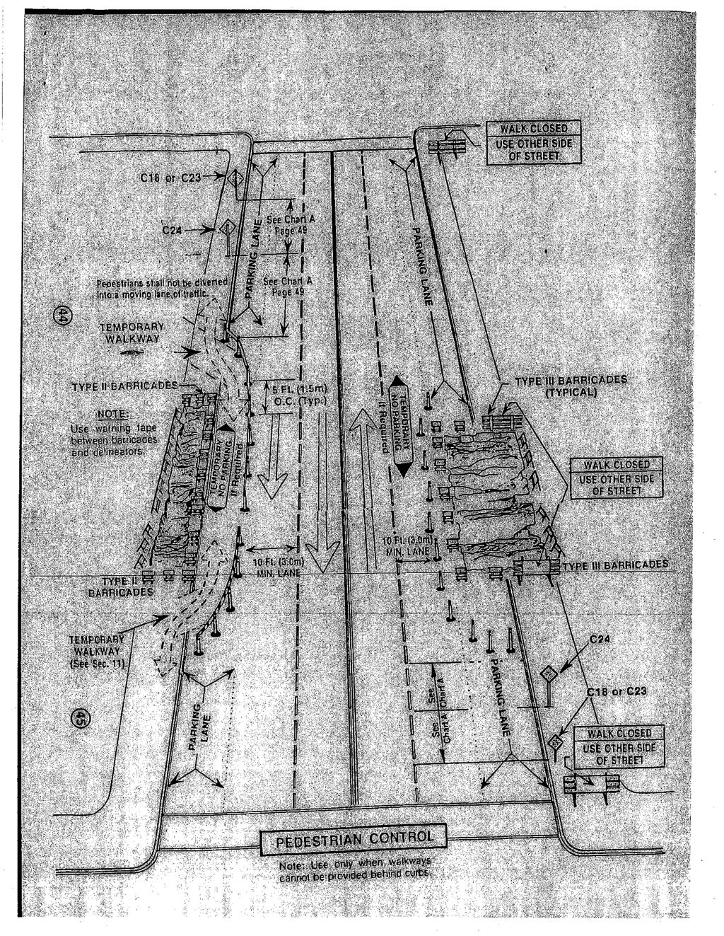
 CONDUITS AND FITTINGS CHAPTER 11 CONDUITS AND FITTINGS The standards and requirements for conduits and fittings used for traffic control signal and lighting systems are presented in this chapter. 11.1
SANITARY SEWERS. B. Construct or relocate building sanitary sewer services, stubs, and connections.
 SANITARY SEWERS PART 1 - GENERAL 1.01 SECTION INCLUDES A. Sanitary Sewer Gravity Mains B. Sanitary Sewer Force Mains C. Sanitary Sewer Services 1.02 DESCRIPTION OF WORK A. Construct sanitary sewer gravity
SECTION FACILITY SANITARY SEWERS
 SECTION 22 13 13 FACILITY SANITARY SEWERS PART 1 - GENERAL 1.1 RELATED DOCUMENTS A. Drawings and general provisions of the Contract, including General and Supplementary Conditions and Division 01 Specification
STANDARD SPECIFICATIONS SECTION BORING AND JACKING. A. Section includes requirements for boring and jacking casing pipe.
 STANDARD SPECIFICATIONS SECTION 02445 BORING AND JACKING PART 1 GENERAL 1.1 DESCRIPTION A. Section includes requirements for boring and jacking casing pipe. 1.2 DEFINITIONS A. Carrier Pipe: Sewer or water
Contact the Jurisdictional Engineer for materials allowed by each jurisdiction.
 Design Manual Chapter 3 - Sanitary Sewers 3C - Facility Design 3C-1 Facility Design A. Capacity of Pipe Pipe sizes 15 inches and smaller should carry the peak flow at a depth of no more than 0.67 of the
All service lines shall conform to the following requirements:
 505 WATER SERVICE INSTALLATION 505.1 DEFINITION A service line is comprised of the piping and related appurtenances including the connection installed from the Des Moines Water Works water main to the
1. B16.1 Cast Iron Pipe Flanges and Flanged Fittings, Class C 111 Rubber Gasket Joints for Ductile Iron Pressure Pipe and Fittings
 SECTION 33 34 00 SANITARY FORCE MAIN PART 1 GENERAL 1.1 SCOPE OF WORK A. This section specifies the requirements for furnishing and installing sanitary force main and appurtenances. The pipe shall be of
SECTION POLYVINYL CHLORIDE (PVC) WATERLINE
 WATERLINE") SECTION 02632 POLYVINYL CHLORIDE (PVC) WATERLINE PART 1 - GENERAL 1.01 SCOPE OF WORK A. Furnish all labor, materials, equipment, and incidentals required, and install polyvinyl chloride (PVC) waterline,
SECTION 02632 POLYVINYL CHLORIDE (PVC) WATERLINE PART 1 - GENERAL 1.01 SCOPE OF WORK A. Furnish all labor, materials, equipment, and incidentals required, and install polyvinyl chloride (PVC) waterline,
B. Subsurface data is available from the Owner. Contractor is urged to carefully analyze the site conditions.
 SECTION 31 23 33 - TRENCHING, BACKFILLING AND COMPACTION PART 1 - GENERAL 1.1 SCOPE A. This Section specifies the requirements for excavating and backfilling for storm sewer, sanitary sewer, water distribution
CONDUITS AND FITTINGS
 CONDUIT AND FITTINGS Rigid Steel Conduit 3801 Rigid PVC Conduit 3803 HDPE Conduit 3803 Flexible Non Metallic Liquid Tight Conduit Type LFNC-B 3804 PVC Coated Urethane Lined Galvanized Rigid Steel Conduit
SECTION DUCTILE IRON FITTINGS. A. This section includes materials, installation, and testing of ductile iron fittings 48 inches and smaller.
 PART 1 - GENERAL 1.1 DESCRIPTION A. This section includes materials, installation, and testing of ductile iron fittings 48 inches and smaller. 1.2 RELATED WORK SPECIFIED ELSEWHERE A. Section 01300 Record
SECTION C1 DUCTILE IRON PIPE AND FITTINGS GENERAL
 SECTION C1 DUCTILE IRON PIPE AND FITTINGS GENERAL This section covers the furnishing and installation of ductile iron water pipe, fittings, thrust restraint and pipe disinfection. Ductile Iron Pipe MATERIALS
2. A preconstruction meeting with the TWA s staff is required prior to initiating construction.
 General: 1. Construct utilities in accordance to TWA approved plans and shop drawings. Any deviation from the approved plans shall be approved by the DEVELOPER S ENGINEER and TWA 2. A preconstruction meeting
CHAPTER 6. Sanitary Sewer
 CHAPTER 6 Sanitary Sewer A. Introduction All proposed developments, subdivisions, and buildings must have a properly designed and constructed sanitary sewer collection system. The system shall provide
SECTION HIGH DENSITY POLYETHYLENE PIPE AND FITTINGS (PRESSURE PIPE)
") SECTION 02623 HIGH DENSITY POLYETHYLENE PIPE AND FITTINGS (PRESSURE PIPE) PART 1 - GENERAL 1.1 SCOPE OF WORK A. Furnish all labor, materials, equipment and incidentals required and install high density
SECTION 02623 HIGH DENSITY POLYETHYLENE PIPE AND FITTINGS (PRESSURE PIPE) PART 1 - GENERAL 1.1 SCOPE OF WORK A. Furnish all labor, materials, equipment and incidentals required and install high density
LANE ENTERPRISES, INC. STANDARDS & SPECIFICATIONS
 LANE ENTERPRISES, INC. STANDARDS & SPECIFICATIONS The following pages are an index of standards and specifications associated with Lane products. For quick reference purposes, Lane products are shown below
SECTION 19 - TRENCH EXCAVATION, BEDDING AND BACKFILL TABLE OF CONTENTS
 SECTION 19 - TRENCH EXCAVATION, BEDDING AND BACKFILL TABLE OF CONTENTS Section Page 19-1 TRENCH EXCAVATION... 19.1 19-1.01 Exploratory Excavation... 19.1 19-1.02 Trench Width... 19.1 19-1.02.A Storm Drain
SPECIFICATIONS FOR STREET CONSTRUCTION WITHIN THE TOWN OF PLAINVILLE
 SPECIFICATIONS FOR STREET CONSTRUCTION WITHIN THE TOWN OF PLAINVILLE BE IT ORDAINED by the Town Council of the Town of Plainville: SECTION 1. SUBDIVISIONS. All subdivisions hereinafter developed within
Read Only Copy Not For Distribution. Chapter 17. Private Potable Water Supply Systems 17.1 GENERAL REGULATIONS 17.2 QUANTITY OF WATER REQUIRED
 Chapter 17 Private Potable Water Supply Systems 17.1 GENERAL REGULATIONS 17.1.1 Applicability The regulations in this chapter apply to any private potable water supply system where plumbing fixtures are
SERVICE LINES, METERS AND APPURTENANCES
 AUGUST02 SECTION 02646 SERVICE LINES, METERS AND APPURTENANCES PART 1 - GENERAL 1.1 DESCRIPTION A. This section concerns materials and installation of corporation stops, curb stops, service lines, meters,
INDUSTRIAL PIPE FITTINGS, LLC
 Page 1 of 9 SPIROLITE MUNICIPAL AND INDUSTRIAL ODOR CONTROL PIPING Municipal wastewater treatment plants, industrial processes and composting facilities can be assured of trouble free transport of foul
CITY OF TAMPA WASTEWATER DEPARTMENT TECHNICAL STANDARDS GUIDELINE. FOR CONSTRUCTION OF WASTEWATER FACILITIES July 2014 Version 6
 CITY OF TAMPA WASTEWATER DEPARTMENT TECHNICAL STANDARDS GUIDELINE FOR CONSTRUCTION OF WASTEWATER FACILITIES July 2014 Version 6 2545 Guy N Verger Boulevard, Tampa, FL 33605 www.tampagov.net TECHNICAL STANDARDS
SECTION PLUMBING PIPING SYSTEMS
 SECTION 15300 PLUMBING PIPING SYSTEMS PART 1 - GENERAL 1.01 SPECIAL NOTICE A. Each contractor shall read all relevant documents, become familiar with the job, the scope of work, type of general construction,
TRENCHLESS CONSTRUCTION (BORING, JACKING, AND TUNNELING)
") PART 1 - GENERAL TRENCHLESS CONSTRUCTION (BORING, JACKING, AND TUNNELING) 1.01 SECTION INCLUDES A. Trenchless Installation of Carrier Pipe with Casing Pipe B. Trenchless Installation of Carrier Pipe without
PART 1 - GENERAL TRENCHLESS CONSTRUCTION (BORING, JACKING, AND TUNNELING) 1.01 SECTION INCLUDES A. Trenchless Installation of Carrier Pipe with Casing Pipe B. Trenchless Installation of Carrier Pipe without
MANHOLES, VAULTS AND CATCH BASINS SECTION A. Section Soil and Aggregate Materials. C. Section Storm Drainage Systems
 SECTION 02607-1 1.0 GENERAL 1.1 SCOPE: A. This section covers the work necessary for the construction of sanitary and storm system manholes, catch basins, and miscellaneous concrete structures complete.
PART VII - WATER SYSTEM DESIGN CRITERIA
 PART VII - WATER SYSTEM DESIGN CRITERIA A. Water Distribution, General 1. The water system layout shall be approved by the City Engineer. The fire hydrant layout shall be approved by the Redwood City Fire
NORTHWESTERN UNIVERSITY PROJECT NAME JOB # ISSUED: 03/29/2017
 SECTION 22 1316 - SANITARY WASTE AND VENT PIPING PART 1 - GENERAL 1.1 RELATED DOCUMENTS A. Drawings and general provisions of the Contract, including General and Supplementary Conditions and Division 01
***************************************************************************************************************
 02720 STORM DRAINAGE SYSTEM *************************************************************************************************************** SPECIFIER: CSI MasterFormat 2004 number 33 40 00. ***************************************************************************************************************
SECTION WATER MAINS CITY OF LEE S SUMMIT, MISSOURI DESIGN CRITERIA
 SECTION 6900 - WATER MAINS CITY OF LEE S SUMMIT, MISSOURI DESIGN CRITERIA 6901 DESIGN CRITERIA A. General 1. The design standards presented in the City of Lee's Summit Design Criteria are the minimum standards
New Fulton State Hospital Energy Control Center and Services Building (ECC/SVC) Project Number: M
 Project Number: M") SECTION 334100 - STORM UTILITY DRAINAGE PIPING PART 1 -GENERAL 1.1 RELATED DOCUMENTS A. Drawings and general provisions of the Contract, including General and Supplementary Conditions and Division 01 Specification
SECTION 334100 - STORM UTILITY DRAINAGE PIPING PART 1 -GENERAL 1.1 RELATED DOCUMENTS A. Drawings and general provisions of the Contract, including General and Supplementary Conditions and Division 01 Specification
Rural Servicing Guidelines
 Rural Servicing Guidelines for Low-Pressure Sanitary Sewer System and Trickle Feed Water Distribution System FOREWORD This manual is intended to provide information to Developers, Engineering and Geotechnical
SECTION 4 - DESIGN STANDARDS FOR WATER DISTRIBUTION FACILITIES
 SECTION 4 - DESIGN STANDARDS FOR WATER DISTRIBUTION FACILITIES 4.1 GENERAL REQUIREMENTS 4.1.1 Water and fire protection distribution facilities are to be provided solely for the purpose of supplying potable
C. Foundation stabilization for pipe and utility structures.
 PART 1 - GENERAL 1.1 SECTION INCLUDES A. Excavating, backfilling, and compacting for utilities, including pipe, structures, and appurtenances. B. Control of water in trenches. C. Foundation stabilization
CHAPTER 110 SEWAGE DISPOSAL
 110-1. Title. 110-6. System rehabilitation. 110-2. Purpose. 110-7. Liability. 110-3. Definitions. 110-8. Conflict with other 110-4. Applicability. regulations. 110-5. Applicable standards for sewage 110-9.
Concrete Pipe Joints Your Best Choice
 Frequently Asked Questions Q. Are joints covered by National Standards? A. Yes. There are ASTM and AASHTO standards for concrete products joints. The various standards are discussed in this publication.
CONCRETE PIPE JOINTS, YOUR BEST CHOICE
 CONCRETE PIPE JOINTS, YOUR BEST CHOICE www.concretepipe.org FREQUENTLY ASKED QUESTIONS Q. Are joints covered by National Standards? A. Yes. There are ASTM and AASHTO standards for concrete products joints.
RICHFIELD CITY CONSTRUCTION STANDARDS
 CONSTRUCTION STANDARDS REVISED OCTOBER 2015 Jones & DeMille Engineering, Inc. [0711-211] 1535 South 100 West Richfield, UT 84701 Ph. 435-896-8266 Fax 435-896-8268 1675 South Highway 10 Price, UT 84501
THE ADVANTAGES HDPE MANHOLES
 NIC HDPE manholes are custom fabricated for many varied applications including municipal and industrial manholes, sewer and storm water manholes, leach ate collection, sewer lift stations, siphon structures,
SECTION CHAIN LINK FENCES AND GATES (GALVANIZED) A. Fence framework, fabric, gates, and accessories.
 A. Fence framework, fabric, gates, and accessories.") SECTION 02830 CHAIN LINK FENCES AND GATES (GALVANIZED) 1.0 GENERAL 1.1 Section Includes A. Fence framework, fabric, gates, and accessories. B. Excavation for post bases; concrete footing for posts. C.
SECTION 02830 CHAIN LINK FENCES AND GATES (GALVANIZED) 1.0 GENERAL 1.1 Section Includes A. Fence framework, fabric, gates, and accessories. B. Excavation for post bases; concrete footing for posts. C.
Daytona Beach Pier Building Renovation Jun 2010
 SECTION 15150 - SANITARY WASTE AND VENT PIPING PART 1 - GENERAL 1.1 RELATED DOCUMENTS A. Drawings and general provisions of the Contract, including General and Supplementary Conditions and Division 1 Specification
DIVISION 3: SEWER. Improvement Design Standards City of Dundee Oregon. Division 3 : Sewer Page 1
 DIVISION 3: SEWER 3.1 DESIGN CRITERIA A. APPLICABILITY 1. These Design Standards shall govern all construction and upgrading of public sanitary sewer facilities in the City of Dundee and applicable work
STANDARD SPECIFICATION FOR CRIBLOCK CONCRETE CRIBWALL
 STANDARD SPECIFICATION FOR CRIBLOCK CONCRETE CRIBWALL 1. SCOPE 2. DESIGN 3. MATERIALS 4. CONSTRUCTION 5. METHOD OF MEASUREMENT AND PAYMENT SCOPE This Specification sets out requirements for the design,
ITEM D-701 PIPE FOR STORM DRAINS AND CULVERTS
 ITEM D-701 PIPE FOR STORM DRAINS AND CULVERTS 701-1 DESCRIPTION 701-1.1 This item shall consist of the construction of pipe culverts, and storm drains, removal of existing storm pipes, connections to existing
SECTION FOUNDATION DRAINAGE
 SECTION 33 41 13 SPEC WRITER NOTES: Use this section only for NCA projects. Delete text between // // not applicable to project. Edit remaining text to suit project. PART 1 - GENERAL 1.1 SUMMARY A. Section
SECTION BASIC ELECTRICAL MATERIALS AND METHODS
 SECTION 26 05 05 BASIC ELECTRICAL MATERIALS PART 1 - GENERAL 1.1 SUMMARY A. Section includes the limited scope construction materials and methods for application with electrical installations as follows:
Section 2: Underground
 Section 2: Underground GENERAL INSTALLATION REQUIREMENTS FOR UNDERGROUND FACILITIES Underground electric service and meter location will be established by NHEC upon site visit. In some instances the type,
GUIDELINES FOR SANITARY DESIGN AND CONSTRUCTION OF MILK PRODUCTS PLANTS (rev )
") Milk and Dairy Food Safety Branch 1220 N Street, Sacramento, CA 95814 GUIDELINES FOR SANITARY DESIGN AND CONSTRUCTION OF MILK PRODUCTS PLANTS (rev. 10-20-2011) The outline below lists sanitary requirements
Milk and Dairy Food Safety Branch 1220 N Street, Sacramento, CA 95814 GUIDELINES FOR SANITARY DESIGN AND CONSTRUCTION OF MILK PRODUCTS PLANTS (rev. 10-20-2011) The outline below lists sanitary requirements
SPECIFICATION FOR PIPE CULVERT CONSTRUCTION
 SPECIFICATION FOR PIPE CULVERT CONSTRUCTION 1. SCOPE Pipe culverts shall be constructed in accordance with this specification and in conformity with the lines, levels and cross-sections shown on the drawings.
Contact Clark Public Utilities Construction Services department at (360) to initiate a request for service.
 to initiate a request for service.") CHAPTER3 Clark Public Utilities Commercial Electric Service Handbook Commercial Underground Services Preparing for the installation The following checklist will assist in preparing a project for the installation
CHAPTER3 Clark Public Utilities Commercial Electric Service Handbook Commercial Underground Services Preparing for the installation The following checklist will assist in preparing a project for the installation
SECTION IV. PIPELINE EXCAVATION AND BACKFILL
 SECTION IV. PIPELINE EXCAVATION AND BACKFILL A. Description of Work B. Surface Types C. Backfill D. Surface Restoration A. DESCRIPTION OF WORK 1. Extent: Excavation of trenches for pipelines shall include
CHAPTER 13 R-5 MANUFACTURED MOBILE HOME PARK RESIDENTIAL DISTRICT
 15.1300 CHAPTER 13 R-5 MANUFACTURED MOBILE HOME PARK RESIDENTIAL DISTRICT 15.1301 SECTION 13.01 STATEMENT OF PURPOSE To provide for manufactured home park development, of long-term duration of stay, in
SECTION I FLEXIBLE PIPE VS. RIGID PIPE (GENERAL)
") h~i:! SECTION I FLEXIBLE PIPE VS. RIGID PIPE (GENERAL) Generally, rigid pipes have the following characteristics: made in discrete lengths use gaskets in joints to form a water-tight seal often produced
h~i:! SECTION I FLEXIBLE PIPE VS. RIGID PIPE (GENERAL) Generally, rigid pipes have the following characteristics: made in discrete lengths use gaskets in joints to form a water-tight seal often produced
Fence and Wall Requirements
 Fence and Wall Requirements Definitions Decorative wall - A wall constructed of stone or other material erected for the sole purpose of providing a decorative and/or landscaped feature, and not to include
Protective Coatings for Underground Utility Concrete Structures. By: John E. Davis Inside Sales & Marketing Specialist: Sauereisen, Inc.
 Protective Coatings for Underground Utility Concrete Structures By: John E. Davis Inside Sales & Marketing Specialist: Sauereisen, Inc. As our cities and municipalities grow older, the utility and wastewater
SEPTIC TANK CONSTRUCTION GUIDELINES
 SEPTIC TANK CONSTRUCTION GUIDELINES Septic tank for this airport will be designed/ built by the general contractor of the building facilities. At the time of the project design, availability of a septic
GUIDELINES FOR SEPTIC SYSTEM DESIGN
 GUIDELINES FOR SEPTIC SYSTEM DESIGN Single Family Residential For multi family or commercial buildings, Or If in the Oakdale area, contact the Department of Environmental Resources Regarding septic system
SECTION TRENCHING & BACKFILLING
 SECTION 02225 - TRENCHING & BACKFILLING 1.0 GENERAL 1.1 Work included in this Section includes trenching and backfilling for underground pipelines and related structures only. 1.2 Reference Specifications
DESIGN OF SEWER SYSTEMS
 Wastewater Engineering (MSc program) DESIGN OF SEWER SYSTEMS Prepared by Dr.Khaled Zaher Assistant Professor, Public Works Engineering Department, Faculty of Engineering, Cairo University 1. Sewer Materials
SECTION EXCAVATION AND BACKFILL FOR UTILITIES AND STRUCTURES
 SECTION 02215 EXCAVATION AND BACKFILL FOR UTILITIES AND STRUCTURES PART 1 - GENERAL 1.1 DESCRIPTION: This section includes materials, testing, and installation of earthwork for excavations, fills, and
SPECIFICATION : BORING AND JACKING
 SPECIFICATION 330524: BORING AND JACKING PART 1.0 GENERAL 1.1 DESCRIPTION 1.1.1 The work of this specification includes all labor, machinery, construction equipment and appliances required to perform in
DESIGN STANDARDS. Division 02 Existing Conditions- Site Work. General
 DESIGN STANDARDS Division 02 Existing Conditions- Site Work General I. This Division includes: A. Demolition B. Clearing and Grubbing C. Excavation, Backfill and Compaction D. Pavement Base E. Paving and
GRAY WATER SYSTEMS FOR RESIDENTIAL BUILDINGS
 INFORMATION BULLETIN / PUBLIC - PLUMBING CODE REFERENCE NO.: LAMC 94.1502.0 Effective: 01-01-2017 DOCUMENT NO.: P/PC 2017-012 Revised: Previously Issued As: P/PC 20014-012 GRAY WATER SYSTEMS FOR RESIDENTIAL
TAMDID PIPES GRP MANHOLE BROCHURE
 TAMDID PIPES GRP MANHOLE BROCHURE 1) Types & Description of Manholes: Tamdid Pipes offer two types of Manholes; Structural and Liner Manholes: a. Structural Manholes Tamdid Pipes offers concentric and
Construction Documents (CDs) Required Signature Blocks and Standard Notes
 Required Signature Blocks and Standard Notes") Development Services Department 100 N. Wilcox Street, Castle Rock CO 80104 Project Manager 720-733-3582 Construction Documents (CDs) Required Signature Blocks and Standard Notes Revised July 17, 2017 INDEMNIFICATION
Development Services Department 100 N. Wilcox Street, Castle Rock CO 80104 Project Manager 720-733-3582 Construction Documents (CDs) Required Signature Blocks and Standard Notes Revised July 17, 2017 INDEMNIFICATION
SECTION STORM DRAINAGE DESIGN, GRADING, AND WATER QUALITY TECHNICAL CRITERIA TABLE OF CONTENTS PAGE 402 STORM DRAINAGE DESIGN CRITERIA 400-1
 CITY OF THORNTON Standards and Specifications Revised: October 2012 SECTION 400 - STORM DRAINAGE DESIGN, GRADING, AND WATER QUALITY TECHNICAL CRITERIA TABLE OF CONTENTS PAGE 401 GENERAL PROVISIONS 400-1
SECTION HIGH DENSITY POLYETHYLENE PIPE AND FITTINGS
 SECTION 02620 PART 1 GENERAL 1.1 SCOPE OF WORK A. Furnish all labor, materials, equipment, and incidentals required to install High Density Polyethylene (HDPE) pressure pipe, fittings, and appurtenances
GRAY WATER SYSTEMS (Reference California Plumbing Code Chapter 16 and 16A) Revised: 6/11/14
 Revised: 6/11/14") Planning and Building Department 525 San Anselmo Avenue Building Division San Anselmo, CA 94960 Phone: (415) 258-4616 Fax: (415) 454-4683 GRAY WATER SYSTEMS (Reference California Plumbing Code Chapter
Planning and Building Department 525 San Anselmo Avenue Building Division San Anselmo, CA 94960 Phone: (415) 258-4616 Fax: (415) 454-4683 GRAY WATER SYSTEMS (Reference California Plumbing Code Chapter
I. Project Overview and Limits. Project Goal
 Scope of Work and Deliverables for Subsurface Utility Engineering (SUE) for both Underground and Overhead Utilities on T.H. 10, and its Connecting Roads under S.P. 8001-40 I. Project Overview and Limits
Sanitary Sewer Extensions, Lift Stations, and Force Mains Engineering Report Form. I. General Information. 1. Name of Facility:
 Oklahoma Department of Environmental Quality Water Quality Division Phone: 405-702-8100 Construction Permitting Section 707 N. Robinson, OKC, OK 73102-6010 P.O. Box 1677, OKC, OK 73101-1677 Sanitary Sewer
MASTERSPEC TECHNICAL SPECIFICATIONS DIVISION 22 PLUMBING
 SECTION 221316 - SANITARY WASTE AND VENT PIPING PART 1 - GENERAL 1.1 SUMMARY A. This Section includes the following soil and waste, sanitary drainage and vent piping inside the building: 1. Pipe, tube,
C900/RJ. CertainTeed. PVC Pipe. with CertainTeed s proven Certa-Lok restrained joint system. Directional Drilling
 1 1 CertainTeed C900/RJ PVC Pipe with CertainTeed s proven Certa-Lok restrained joint system Directional Drilling Underground Water Mains and Restrained, Non-Metallic Change-of-Direction Fittings (No Thrust
TOILET FACILITIES AND SEWAGE DISPOSAL REGULATIONS
 REPUBLIC OF THE MARSHALL ISLANDS ENVIRONMENTAL PROTECTION AUTHORITY TOILET FACILITIES AND SEWAGE DISPOSAL REGULATIONS 1990 INDEX PART I - GENERAL PROVISIONS 1. Authority 2. Purpose 3. Effective date 4.
SPECIAL CONDITIONS FOR PIPE JACKING (PJ) October, 2006
 October, 2006") Michigan Department Of Transportation 3703C (11/06) 1 Materials 1.1 Pipe SPECIAL CONDITIONS FOR PIPE JACKING (PJ) October, 2006 Page 1 of 5 The type of pipe used for the pipe jacking method shall be capable
Michigan Department Of Transportation 3703C (11/06) 1 Materials 1.1 Pipe SPECIAL CONDITIONS FOR PIPE JACKING (PJ) October, 2006 Page 1 of 5 The type of pipe used for the pipe jacking method shall be capable
Sclairpipe VERSATILE HIGH DENSITY POLYETHYLENE PIPE
 Sclairpipe VERSATILE HIGH DENSITY POLYETHYLENE PIPE Sclairpipe Sclairpipe high density polyethylene (HDPE) pipe represents the latest advances in both material and manufacturing techniques. Since 1968,
SECTION EXCAVATING, BACKFILLING, AND COMPACTION FOR UTILITIES
 SECTION 02221 EXCAVATING, BACKFILLING, AND COMPACTION FOR UTILITIES PART 1 GENERAL 1.01 SUMMARY A. Related Sections: 1. 02200 - Earthwork. 2. 02660 - Water Systems. 3. 02720 - Storm Drainage System. 4.
CITY OF ASTORIA PUBLIC WORKS ENGINEERING DIVISION ENGINEERING DESIGN STANDARDS FOR IN-FILL DEVELOPMENT
 CITY OF ASTORIA PUBLIC WORKS ENGINEERING DIVISION ENGINEERING DESIGN STANDARDS FOR IN-FILL DEVELOPMENT Adopted by City Council: May 21, 2007 X:\General Eng\DESIGN STANDARDS\Engineering Design Standards
SECTION TAPPING SLEEVES AND VALVES
 SECTION 33 12 16.17 TAPPING SLEEVES AND VALVES PART 1: GENERAL 1.01 SCOPE Furnish, install and test all tapping sleeves, tapping valves, and tapping saddles as shown on the Drawings. 1.02 RELATED WORK
PIPE BURSTING GRAVITY SEWER MAINS WITH HDPE PIPE
 PIPE BURSTING GRAVITY SEWER MAINS WITH HDPE PIPE SUGGESTED STANDARD SPECIFICATION January, 2012 Prepared by International Pipe Bursting Association Thanks to the following participants for the development
SWIMMING POOL PERMIT AND INSPECTION REQUIREMENTS
 Building Inspections SWIMMING POOL PERMIT AND INSPECTION REQUIREMENTS Permit Applications Pool permit applications are now being accepted online at http://etrakit.flower-mound.com/. Starting November 1,
SECTION 806 MANHOLE REHABILITATION
 SECTION 806 MANHOLE REHABILITATION 806-1 DESCRIPTION: This specification consists of all work, materials, labor and equipment required for manhole rehabilitation for the purpose of eliminating infiltration
ENGINEERING DESIGN & IMPROVEMENT STANDARDS
 ENGINEERING DESIGN & IMPROVEMENT STANDARDS 2016 Prepared by: Engineering Division For latest edition of these Improvement Standards, refer to City of Visalia website at: www.visalia.city/engineeringdocuments
Austin Technical Manuals - Standard Specifications Preservation of Trees and Other Vegetation (610S) 03/27/2000
 03/27/2000") Austin Technical Manuals - Standard Specifications Preservation of Trees and Other Vegetation (610S) 03/27/2000 610S.1 This item shall govern the proper care and treatment of all trees and other vegetation
Austin Technical Manuals - Standard Specifications Preservation of Trees and Other Vegetation (610S) 03/27/2000 610S.1 This item shall govern the proper care and treatment of all trees and other vegetation
BILL OF QUANTITY ENGINEERING & MANAGEMENT CONSULTING CENTRE. "Beit Hanoun Emergency Water Supply Project"
 "Beit Hanoun Emergency Water Supply Project" " Rehabilitation and Construction of Beit Hanoun Water Network " BILL OF QUANTITY ENGINEERING & MANAGEMENT CONSULTING CENTRE Bill of Quantities PREAMBLE TO
Infiltration Guidelines
 Appendix E Infiltration Guidelines As a stormwater management method, infiltration means retaining or detaining water within soils to reduce runoff. Infiltration can be a cost-effective method to manage
PVC Fittings & Laterals for Solid-Wall PVC Sewer Pipe
 Design and Installation Guide PVC Fittings & Laterals for Solid-Wall PVC Sewer Pipe TABLE OF CONTENTS Introduction 2 Products 3 Main-Line Fittings & Service-Line Fittings 3-4 Connections to Dissimilar