IAEA-TECDOC Spent Fuel Reprocessing Options
|
|
|
- Natalie Melina Hopkins
- 6 years ago
- Views:
Transcription
1 IAEA-TECDOC-1587 Spent Fuel Reprocessing Options August 2008
2 IAEA-TECDOC-1587 Spent Fuel Reprocessing Options August 2008
3 The originating Section of this publication in the IAEA was: Nuclear Fuel Cycle and Materials Section International Atomic Energy Agency Wagramer Strasse 5 P.O. Box 100 A-1400 Vienna, Austria SPENT FUEL REPROCESSING OPTIONS IAEA, VIENNA, 2008 IAEA-TECDOC-1587 ISBN ISSN IAEA, 2008 Printed by the IAEA in Austria August 2008
4 FOREWORD The IAEA continues to give a high priority to safe and effective implementation of spent fuel management. The purpose of this publication is to review current and future options for the reprocessing of spent nuclear fuels and the future direction of the nuclear fuel cycle most likely to achieve the objectives of assured energy supply, environmental protection, economic feasibility, and safeguards of special nuclear materials. Substantial global growth of nuclear electricity generation is expected to occur during this century, in response to environmental issues and to assure the sustainability of the electrical energy supply in both industrial and less-developed countries. This growth carries with it an increasing responsibility to ensure that nuclear fuel cycle technologies are used only for peaceful purposes. Recently, proposals have been set forth by the IAEA Director General, governments of the United States of America and Russian Federation for the internationalization of the nuclear fuel cycle. These proposals entail an implied need for the development of innovative means for closure of the nuclear fuel cycle as advanced reactors (Generations III and IV) are deployed and as the quantities of material in the fuel cycle are set to increase to levels several times larger than at present. Such increases can cause stress to the international non-proliferation regime and create undue problems for nuclear waste disposal if not dealt with through open and comprehensive international collaboration. The proper management of spent fuel arising from nuclear power production is a key issue for the sustainable development of nuclear energy. While reprocessing of spent fuel was historically the favored strategy for the back end fuel cycle, in the past few decades some countries have turned to other options. Specifically some countries have adopted a direct disposal or a wait and see strategy, partly in response to concerns such as nuclear weapons proliferation, public acceptance and economics. Some other countries have continued to develop and improve closed fuel cycle technologies. The IAEA has issued several publications in the past that provide technical information on the global status and trends in spent fuel reprocessing and associated topics, and one purpose of this present publication is to provide an update of this information. However, the scope of this publication has been significantly expanded in an attempt to make it more comprehensive by including more information on emerging technologies. A Scientific Forum on the topic Fuel Cycle Issues and Challenges, held during the 48th General Conference of the IAEA on September 2004 provided an opportunity to review and discuss several of the issues associated with spent fuel management and to provide some of the input to finalize this publication. For the preparation of this publication, a Technical Meeting (TM) was held in October 2005, preceded by a consultancy meeting in December Additional Consultancy Meetings were held in October 2006 and April The preliminary draft has subsequently been reviewed and revised several times by the contributors themselves and by other reviewers. The contributions of all who brought indispensable help in drafting and editing the publication (listed at the end of the publication) are greatly appreciated. The IAEA staff member responsible for this publication was Z. Lovasic of the Division of Nuclear Fuel Cycle and Waste Technology.
5 EDITORIAL NOTE The papers in these proceedings are reproduced as submitted by the authors and have not undergone rigorous editorial review by the IAEA. The views expressed do not necessarily reflect those of the IAEA, the governments of the nominating Member States or the nominating organizations. The use of particular designations of countries or territories does not imply any judgement by the publisher, the IAEA, as to the legal status of such countries or territories, of their authorities and institutions or of the delimitation of their boundaries. The mention of names of specific companies or products (whether or not indicated as registered) does not imply any intention to infringe proprietary rights, nor should it be construed as an endorsement or recommendation on the part of the IAEA. The authors are responsible for having obtained the necessary permission for the IAEA to reproduce, translate or use material from sources already protected by copyrights.
6 CONTENTS SUMMARY INTRODUCTION Global statistics in spent fuel management Background of the IAEA activities in the field Scope of work Global evolution of spent fuel management options Technical challenges Non-technical challenges REPROCESSING OPTIONS FOR SPENT FUEL MANAGEMENT Historical background and current status of reprocessing options in industrial scale Prospects for advanced fuel cycle strategies Advanced reprocessing options RESEARCH AND DEVELOPMENT (R&D) IN SUPPORT OF ADVANCED REPROCESSING OPTIONS Major actinides separation technologies R&D on Hydrometallurgical processes (Aqueous technologies) in some countries Pyrometallurgical processes (non aqueous technologies, the dry route ) Exploratory R&D on non- aqueous innovative processes Status of R&D on non aqueous processes by fuel type Minor actinides separation Aqueous processes Non-aqueous processes Group actinide separation technologies Fission and activation products separation technologies Alternative routes to transmutation: conditioning in an inert matrix ISSUES AND CHALLENGES RELATED TO SPENT FUEL REPROCESSING Resources management and economics Basic economic principles (adopted from INPRO methodology) Economic analysis and comparison Cost categories Factors affecting economics Proliferation risk reduction General background of proliferation issues Proliferation assessment methodology Physical protection Environmental impact issues International safety standards Public acceptance Modeling tools... 57
7 International Atomic Energy Agency OECD/NEA Dynamic Model of Nuclear Development (DYMOND) AFCI Module COSI CONCLUSIONS REFERENCES ABBREVIATIONS ANNEX I. TABLES AND FIGURES ANNEX II. SOME SPENT NUCLEAR FUEL COMPOSITION DATA ANNEX III. COUNTRY REPORTS The back-end of the fuel cycle in France: Status and prospects...79 M. Giroux, J-M. Grygiel, B. Boullis, M. Masson, F. Storrer Spent fuel treatment options and application An Indian perspective P.K. Dey Spent fuel treatment options in Japan Gunzo Uchiyama Spent nuclear fuel management system in the Russian Federation, SNF stockpile and plans for reprocessing A.V. Khaperskaya, Ev. G. Kudryavtsev Development of partitioning methods in the United States of America nuclear fuel cycle program J.J. Laidler LIST OF PARTICIPANTS AND CONTRIBUTORS TO DRAFTING AND REVIEW
8 SUMMARY As the options for spent fuel management may in the long term diversify due to evolving requirements and new priorities in strategic criteria, it is worthwhile identifying viable technical options for spent fuel treatment and their applicability to spent fuel management. The objective of this publication is to provide an update on the latest developments in nuclear reprocessing technologies in the light of new developments on the global nuclear scene. The background information on spent fuel reprocessing is provided in Section One. Substantial global growth of nuclear electricity generation is expected to occur during this century, in response to environmental issues and to assure the sustainability of the electrical energy supply in both industrial and less-developed countries. This growth carries with it an increasing responsibility to ensure that nuclear fuel cycle technologies are used only for peaceful purposes. In Section Two, an overview of the options for spent fuel reprocessing and their level of development are provided. A number of options exist for the treatment of spent fuel. Some, including those that avoid separation of a pure plutonium stream, are at an advanced level of technological maturity. These could be deployed in the next generation of industrial-scale reprocessing plants, while others (such as dry methods) are at a pilot scale, laboratory scale or conceptual stage of development. In Section Three, research and development in support of advanced reprocessing options is described. Next-generation spent fuel reprocessing plants are likely to be based on aqueous extraction processes that can be designed to a country specific set of spent fuel partitioning criteria for recycling of fissile materials to advanced light water reactors or fast spectrum reactors. The physical design of these plants must incorporate effective means for materials accountancy, safeguards and physical protection. Section four deals with issues and challenges related to spent fuel reprocessing. The spent fuel reprocessing options assessment of economics, proliferation resistance, and environmental impact are discussed. The importance of public acceptance for a reprocessing strategy is discussed. A review of modelling tools to support the development of advanced nuclear fuel cycles is also given. As a conclusion, spent fuel reprocessing options have evolved significantly since the start of nuclear energy application. There is a large body of industrial experience in fuel cycle technologies complemented by research and development programs in several countries. 1
9 1. INTRODUCTION Management of spent fuel arising from nuclear power production has long been considered an important issue due to the political, economic, and societal implications associated with it. In view of the large amount of spent fuel being progressively added to the cumulative inventory in the world, the significance of spent fuel management will continue to grow in the future. While nuclear industry has successfully managed spent fuel quantities arising from nuclear power production in the past, a variety of issues have been raised through considerations of the long term strategy options for spent fuel management. It would be crucial to resolve or mitigate those issues for enhancing acceptance of the anticipated role of nuclear energy in the sustainable development in the future. The expected growth of nuclear energy generation in the world carries with it an increasing responsibility to ensure that nuclear fuel cycle technologies are used only for peaceful purposes. Recently, proposals have been set forth by the IAEA Director General, and governments of the United States of America and Russian Federation for the internationalization of the nuclear fuel cycle. These proposals entail an implied need for the development of innovative means for closure of the nuclear fuel cycle as advanced reactors (Generations III and IV) are deployed and as the quantities of material in the fuel cycle are set to increase to levels several times larger than at present. Such increases can cause stress to the international non-proliferation regime and create undue problems for nuclear waste disposal if not dealt with through open and comprehensive international collaboration. A central goal of nuclear sustainable development is to enhance the effectiveness of natural resource utilization and to reduce the volume and long term radiotoxicity of high level waste employing partitioning and transmutation of minor actinides while the cost of energy products remain economically viable Global statistics in spent fuel management Currently about thm spent fuel are unloaded every year from nuclear power reactors worldwide (Figure 1). This is the most important continuous growing source of civil radioactive materials generated, and thus need to be managed appropriately. Also, this annual discharge amount is estimated to increase to some thm by The total amount of spent fuel cumulatively generated worldwide by the beginning of 2004 was close to thm of which thm has been reprocessed. The world commercial reprocessing capacity is around tonnes per year. Projections indicate that the cumulative amount generated by the year 2010 may be close to thm with a corresponding increase in reprocessed fuel. By the year 2020, the time when most of the presently operated nuclear power reactors will approach the end of their licensed operation life time, the total quantity of spent fuel generated will be approximately thm Background of the IAEA activities in the field The recent trend toward renewal of interest in nuclear power as a futuristic energy option calls for development of innovative nuclear systems in search of technical evolution for sustainable development. Several national and international initiatives have also been launched for spent fuel reprocessing methods with a long term vision for technical innovation in spent fuel management. 2
10 Having recognized the needs for innovative systems, the IAEA has initiated its International Project on Innovative Nuclear Reactors and Fuel Cycles (INPRO) several years ago, with a view to assist Member States in the development and deployment of nuclear systems by providing an umbrella for investigations in the field. With Phase I of the INPRO project being wrapped up, the INPRO assessment methodology is being validated on the basis of several case studies that have been performed by INPRO members. In recognition of the importance of fuel cycle issues, a Scientific Forum on the topic Fuel Cycle Issues and Challenges, was held during the 48th General Conference of the IAEA (20-22 September 2004), which provided an opportunity to review technology and discuss several of the issues associated with spent fuel management. Another recent initiative launched by IAEA with an implication on spent fuel management is the Multinational Approach (MNA) to nuclear fuel cycles which was also a topic of the Scientific Forum during the 48 th General Conference. In 2005, IAEA published an International Expert Group report on Multilateral Approaches to the Nuclear Fuel Cycle. This report formulated the initiative on Multilateral Fuel Cycle Facilities that would provide assurances of fuel supply and assurances of proliferation resistance [1]. Cumulative Spent Fuel Arisings, Storage and Reprocessing, tones HM SF Discharged SF Stored SF Reprocessed Year Figure 1. Trends in spent fuel management. The IAEA activities in spent fuel management have evolved in response to the changing needs and interests of its Member States. The status and trends in the Member States through the past decades have been closely surveyed and reflected in the formulation of IAEA programs which have dealt with a variety of technical and institutional topics. In recognition of the importance of spent fuel reprocessing in the back end of the fuel cycle, the IAEA has provided a forum for exchange of information on the status and trends in spent fuel reprocessing since the 1970s, from which several publications have been issued [2], [3], [4], [5], [6]: IAEA-TECDOC-115 Reprocessing of Highly Irradiated Fuel (1970) IAEA-TECDOC-333 Treatment of Irradiated LWR Fuel (1985) IAEA-TECDOC-1103 Status and Trends in Spent Fuel Reprocessing, (1999) 3
11 IAEA-TRS-435 Implications of Partitioning and Transmutation in Radioactive Waste Management, (2004) IAEA-TECDOC-1467, Status and Trends in Spent Fuel Reprocessing (2005) The latest publication (IAEA-TECDOC-1467) had a scope enlarged to cover emerging technologies including dry processes, as well as the conventional Purex based technologies which have been the focus of previous publications, with a view to provide a transition bridge toward new trends including a linkage to the INPRO initiative. As the options for spent fuel management may in a long term diversify due to evolving requirements and new priority in strategic criteria, it would be worthwhile to identify viable technical options for spent fuel reprocessing and their applicability to spent fuel management. Following the June 2006 International Conference on the Management of Spent Fuel from Nuclear Power Reactors held in Vienna, the scope of this document was broadened to include policy, safety and security aspects of spent fuel management. The Nuclear Fuel Cycle and Materials Section of the IAEA Department of Nuclear Energy has several programs that may in the long run provide additional inputs to spent fuel management options. Projects on Nuclear Power Reactor Fuel Engineering and on Topical Nuclear Fuel Cycle Issues are dealing with developments in their respective area that can in future widen spent fuel management options. The latest work on thorium fuel cycle, management of reprocessed uranium and viability of recycling fissionable materials in reactors [7] are all summarizing research results that may provide or affect additional reprocessing options [8], [9], [10]. The Joint Convention on the Safety of Spent Fuel Management and on the Safety of Radioactive Waste Management and the IAEA Safety Standards provide a framework for the international safety regime for spent fuel management. The transport of radioactive material, including spent fuel, provides a well established example of this international safety regime through nearly universal application of the IAEA Transport Regulations Scope of work The purpose of this document is to review and provide an updated evaluation on spent nuclear fuel (SNF) reprocessing options with emphasis on reprocessing technologies to improve sustainability of nuclear energy. A wider term of spent fuel treatment options would include an extensive range of processes for spent fuel management which would follow interim storage of spent fuel including disposal. This TECDOC however, is limited to reprocessing of spent fuel with the intent to reuse fissionable material. Sustainability, waste management and proliferation risk reduction were key issues in reviewing the fuel reprocessing options. This document attempts to provide an assessment of status of relevant options, for managing the back end of the fuel cycle. It also includes description of some modeling tools for spent fuel analysis Global evolution of spent fuel management options Safe management of growing inventories of spent fuel has significant implications with regard to the future sustainability of nuclear energy. 4
12 Existing facilities have significantly evolved by implementing new technological advances (see Chapter 3.1) to address several key issues such as minimization/elimination of secondary waste stream, reduction of proliferation risk (no pure plutonium stream, e.g. Japan Rokkashomura plant). Technical innovations addressed in recent international initiatives, such INPRO (IAEA), Gen IV and GNEP (USA), and MICANET (EU) are addressing several issues associated with future nuclear systems (reactor and associated fuel cycle) which are dealing simultaneously with energy supply, environmental impact, economics, non-proliferation, nuclear safety and security. These are key issues to the expansion of nuclear energy. Over the course of nuclear power development, several options for spent fuel management have evolved. The envisaged strategy of reprocessing followed by recycling in breeder reactors from the beginning of peaceful use of nuclear energy has eventually evolved into a policy toward either (1) reprocessing followed by recycling in thermal reactors in some countries as a result of lengthy delays in breeder reactor deployment, coupled with the availability of international fuel cycle services in existing facilities, or (2) direct disposal of spent fuel in a growing number of countries as a result of concerns about nuclear proliferation and economic considerations as the growth in nuclear generation and demand for natural uranium resources failed to materialize in the latter part of the previous millennium. With the exception of a few countries, however, implementation of the policy calling for spent fuel disposal has encountered continuing delays due to controversies hampering geologic repository site selection and development. From the beginning of the new millennium, there have been growing aspirations for innovative technologies in nuclear energy, given the anticipated, significant contributions by nuclear energy in mitigating global warming concerns. It is therefore essential to consider technical innovations in future nuclear fuel cycles, which can improve the sustainability of nuclear energy by (1) reducing substantially the uranium consumption per unit of energy produced, and (2) further reducing the long-term radiotoxicity of high-level waste through their ability to burn the majority of long-lived minor actinides, such as neptunium and americium, in addition to the major actinides (uranium and plutonium) as presently achieved by the PUREX separation process, while keeping the costs of energy products, in particular electricity, economically affordable [1]. These are indeed the objectives being pursued by the current initiatives for development of innovative nuclear systems (i.e., reactor and fuel cycle technologies). It should be stressed that each country (see country reports in Appendix 1) is facing a different situation with regard to: Global energy mix and energy policy, current status and prospects for the contribution of nuclear power, and commitment to the reduction of greenhouse gas emissions such as CO 2, Availability of fissile materials resources, Nuclear power fleet (number of units, reactor(s) type(s) and fuel cycle technologies implemented, etc.), 5
13 Inventory of radioactive materials (including legacy waste) resulting from past and waste management practices (see information on spent fuel composition in Annex I2), Choice and capacity of candidate geologic formations chosen for ultimate disposal, Public (and political) support for nuclear energy. These current considerations are drivers for the choice of a national back-end strategy with the following possibilities (see Figure 2): Direct Disposal or Once-through Fuel Cycle Storage and Postponed Decision or Wait and See Option Reprocessing and Recycling or Closed Fuel Cycle Direct disposal Storage and postponed decision? Treatment and Recycling (France, Japan, Russia, India) Figure 2. Three basic strategies for the management of spent fuel. Drivers for closed cycle and advanced recycling strategies There are five key considerations for a closed fuel cycle strategy and R&D on advanced fuel cycles to further improve it [6]: Conservation of natural resources Optimization of waste management and disposal conditions, Minimization of environmental impact (see Chapter 4), Fuel cycle economics (see Chapter 4), Proliferation resistance (see Chapter 4). 6
14 Compared to the once through fuel cycle strategy, the present approach based on the PUREX separation process and recycling of plutonium as mixed oxide fuel (MOX) in light water reactors offers the following advantages: Improve use of fissile materials resources by up to 25%, Leads to a reduction of conditioned/packaged high level and long lived waste volume to be disposed of, thanks to the removal uranium and plutonium, Decreases the long-term radiotoxicity of HLW to be disposed of. Innovative separation method now under development would also allow for the removal of minor actinides, such as americium and neptunium, therefore further optimizing the utilization of fissile materials and alleviating the heat constraints on the final repository. It must be noted that some countries are concerned with the potential disadvantages of the current fuel reprocessing strategies like the cost of reprocessing and potentially lower proliferation resistance. Impact on Geologic Repository The design and capacity of a geologic repository depends on: Decay heat release and time for packages to cool down, Long term radiotoxicity of the waste, Mobility and transport of radio-elements in case of loss of containment and rupture of all barriers surrounding the waste package (depending on the geochemistry of the selected site with either oxidizing or reducing conditions). The long term decay heat release and radiotoxicity of a standard PWR spent fuel vs. cooling time are illustrated below in Figures 3 and 4. The long term environmental impact of the disposed HLW therefore depends on: Its inventory as a result of the nuclear power plants fleet composition (reactor types) and selected fuel cycle strategy, The solubility and migration of the elements in the selected geological site. As a result, the relative radiological impact of each of the nuclides contained in the disposed HLW varies depending on the repository concept and the type of host rock. Emerging fuel cycle strategies The emerging fuel cycle strategies and their respective merits to address the mentioned key drivers are summarized below: 7

15 Figure 3. Decay heat in storage vs. cooling time. Figure 4. Potential radiotoxicity vs. cooling time Figure 4. Potential radiotoxicity vs. cooling time. Co-management of U and Pu to improve the proliferation resistance of spent fuel reprocessing. 8
16 Selective separation and heterogeneous recycling of minor actinides to further reduce decay heat of the waste to be disposed of in a geologic formation. Heat load of the repository to host ultimate waste can already be significantly reduced with Pu removal as Pu is the major source of the decay heat and for long term potential radiotoxicity of PWR spent fuel. Selective separation and heterogeneous recycling of minor actinides could further reduce the decay heat of the wastes disposed of in a geologic formation. Ultimately, a more challenging goal of achieving group extraction and homogeneous recycling of actinides in an integrated fuel treatment and refabrication facility to further simultaneously minimize the proliferation risk associated with the back-end of the fuel cycle, and the heat load of the repository for the waste to be disposed. These three fuel cycle strategies are sketched in the Figure 5 below: U U U R T FP MA R T FP R T FP MA U Pu U Pu U Pu MA U & Pu Recycling Heterogeneous Recycling Homogeneous Recycling Technical challenges Figure 5. Fuel cycle strategies. Resolving the challenges associated with emerging fuel cycle strategies include nonproliferation, minimization of industrial discharges from fuel reprocessing facilities, and economic competitiveness. All nations that have signed the Non-Proliferation Treaty (NPT) have the right to pursue enrichment and reprocessing for peaceful purposes in conformity with Articles I and II of the Treaty. However, there is no silver bullet technology that can be built into an enrichment plant or reprocessing plant that can prevent a country from diverting its national fuel cycle facilities to non-peaceful use. Therefore, from the standpoint of resistance to proliferation caused by a national commitment to weapon development, there are technological limits to the non-proliferation benefits offered by any of the advanced chemical separations technologies, which can be modified to produce plutonium if a nation is willing to withdraw from, or violate, its safeguards obligations. This is one of the driving elements for the Global Nuclear Energy Partnership (GNEP) initiated by the U.S. [11] and joined by China, France, Japan and Russia (joint statement on May 21, 2007), which aims to provide the benefits of nuclear electricity at a reasonable cost to those countries that choose not to pursue uranium enrichment and spent fuel reprocessing. By doing so, these countries can avoid the cost of building a fuel cycle infrastructure (enrichment, reprocessing, fuel fabrication and perhaps even high level waste disposal). It should be noted that a commercial plant providing international fuel cycle services would essentially be prevented to do so as the scrutiny of its foreign customers would provide a strong extrinsic non-proliferation control. 9
17 Significant reductions have been achieved in the radiological discharges as illustrated by the 2000 Marina II Study by the European Community. The radiological discharges from the La Hague and Sellafield reprocessing plants were contributing ~5% to the collective dose from all industrial radioactive discharges into the North Sea. oil and gas, and phosphates operations were contributing respectively ~35 and ~55%. However, the nuclear industry remains under pressure to further reduce environmental discharges from reprocessing facilities. The competitive edge, or lack thereof, of innovative fuel cycle schemes as compared with schemes based on existing technologies is difficult to quantify with accuracy, given the various degrees of uncertainties affecting established versus conceptual technologies. Clearly, even if the back-end fuel cycle costs represent a small fraction of overall costs, they must remain reasonably competitive when all alternatives are considered. Maybe as important, if not more so, are the investment risks that have to be acceptable to those considering investing in fuel reprocessing options. These risks must be weighted against waste disposal benefits and intangibles such as global proliferation risk mitigation Non-technical challenges Political will and public acceptance will be required to construct the facilities needed to support advanced fuel cycles. Recognition of the societal significance of the potential benefits of the technology together with sufficient public involvement in handling environmental matters will be key in obtaining government and local public support. 2. REPROCESSING OPTIONS FOR SPENT FUEL MANAGEMENT This section provides an overview of considered spent fuel processing options and the status of their development. The major options are described in more detail in Section Historical background and current status of reprocessing options in industrial scale Irradiated nuclear fuels were first reprocessed in the 1940s using pyrochemical and precipitation processes. These separation methods were soon replaced by the solvent extraction process (hydrometallurgy), which is better suited to continuous, large scale, remote operation, allowing for the separation of 3 main streams of nuclides (uranium, plutonium, and waste, i.e. fission products and minor actinides). Different solvent extraction systems were explored before the discovery of an efficient extraction system. The combination known generically as PUREX (which utilizes the extractant tributyl phosphate (TBP) mixed in a largely inert hydrocarbon solvent) soon replaced all earlier solvent extraction media because of its high performance in industrial scale plants. The PUREX process was used for several decades in the production of separated plutonium for military purposes; during that time, process was optimized for maximum efficiency of recovery and purification. The first plant based on hydrometallurgy emerging on the market to reprocess spent fuel from commercial power plants was built in Belgium in the sixties on a multinational basis (EUROCHEMIC). In the seventies, based on the assumptions of a rapid growth in nuclear energy and uranium demand, industrial implementation of the closed fuel cycle using the PUREX process was further extended with the reprocessing of used fuel coming initially from gas-cooled reactors, 10
18 later on from LWRs (BWRs and PWRs), and then from PHWR reactors. The recycling of plutonium in the form of mixed-oxide fuel (UO 2 -PuO 2 or MOX fuel) in fast breeder reactors (expected at that time to be deployed on a large scale) was regarded as the standard strategy. In the eighties, the worldwide development in nuclear energy turned out to be more modest than originally planned and prospects for the implementation of fast reactors associated with a closed fuel cycle were progressively postponed in several countries (see country reports). However, several countries including France, Japan, UK, Russia and India (see also country report for India), continuously developed, improved and adapted the PUREX technology. In France for the MOX-fuel fabrication, in Russia for U recycling in RBMK fuel, in India for the U recycling in PHWR fuel and MOX for FBR. As a result of this fuel cycle strategy based on PUREX, the volume (and radiotoxicity) of highly radioactive and long-lived waste to be disposed of in these countries were significantly reduced as compared to a once-through fuel cycle, with inventory high level waste restricted to fission products and minor actinides (which are conditioned in a very stable glass matrix), and very small losses of plutonium to the waste stream. As a result of several decades of industrial feed-back in the development of the closed fuel cycle strategy based on the PUREX process, one can mention the following major achievements: - High efficiency and reliability (large amount of used fuel processed with good statistics, see countries reports), - The fabrication of high quality UO 2 and MOX fuels for LWRs and fast reactors, - Continuous decrease of solid waste volume, effluents and environmental impact in terms of radiation doses. Among the other options for the management of nuclear waste, one can distinguish two different approaches for the back-end of the fuel cycle: The wait and see strategy : in a context of uncertain energy market, many countries have opted for the interim storage of spent fuel; Direct disposal of spent fuel in underground geological repositories (as already decided in few countries like Finland or Sweden for instance). It is also worth mentioning the distinct situation of the United States of America (USA). After having developed the closed fuel cycle in the early days of nuclear power developments, the USA switched to a once-through cycle in 1978 mainly because of proliferation concerns. Early in 2006, a major political transition occurred with the launching of the Global Nuclear Energy Partnership (GNEP) initiative. This proposed return to the closed fuel cycle was decided both for domestic reasons (especially regarding the optimization of the capacity of the geological repository for ultimate waste) and for the implementation of a multinational approach to the fuel cycle in a context of a worldwide renaissance (and prospects for a sustainable development) of nuclear power and minimization of proliferation risk. Current capacities of spent fuel reprocessing status of reprocessing facilities and reprocessed fuel data are given in ANNEX I (Tables I-1, I-2 and I-3). 11
19 2.2. Prospects for advanced fuel cycle strategies Given expectations that it is just a matter of time for a new generation of nuclear systems (reactors and associated fuel cycle) to emerge, interim storage in the framework of a wait and see strategy can be seen as a way to provide some flexibility in the management of used fuels and nuclear waste. Such a wait and see policy is based on the confidence that nuclear science and technology will continue to progress towards the sustainability of nuclear power while addressing key issues such as: - A competitively-priced and reliable supply of energy without emission of greenhouse gases; - An optimum use of the available natural resources of fissile materials (uranium or thorium), an optimized management of waste (limited amount of ultimate waste to be disposed of), and a safe interim storage without significant environmental impact even on the long term (several hundreds of years); - A continuously improved nuclear safety; - A reduced proliferation risk. Developments of advanced reprocessing technologies are directed on: - Reduction of cost of reprocessing in comparison with PUREX-process cost, and also in comparison with expenses for direct spent fuel disposal in the open nuclear cycle; - Recovery of all actinides and long-living fission products for reduction of volumes and toxicity of the waste products for disposal, and, hence, for decrease in expenses for construction and operation of repository and increase of long-term safety of a repository, - Creation of the flexible technologies, capable to be adapted to changing conditions and requirements, including new types and structures of fuel, reactors of the third and fourth generations, high degrees of spent fuel burning out etc., - With recycling of all the fissionable products (reducing the proliferation risk) and thus, as a final result, a better public acceptance of nuclear power. These key issues are at the cornerstone of various national and international initiatives launched to further develop advanced fuel cycles such as: The INPRO initiative and the multinational approach (MNA) of the fuel cycle as proposed by the IAEA; The programs launched by the USA such as the Advanced Fuel Cycle Initiative, the GENERATION IV International Forum, The Russian initiative on the creation of multilateral centers for the provision of nuclear fuel cycle services The USA initiative Global Nuclear Energy Partnership ; 12
20 The R&D undertaken in the framework of the French 2006 legislation on the management of spent fuel and nuclear waste, The Fast reactor Cycle Technology development (FaCT) project in Japan. These initiatives are driving the R&D on various advanced separation methods aiming at addressing the following goals: Enhanced sustainability and proliferation risk reduction with the emergence of new processes allowing for the co-management of U and Pu (and possibly U-Pu-Np), allowing for further optimization of the repository capacity and reduction of the potential radio-toxicity of waste for disposal; Possible separation and heterogeneous recycling of minor actinides, and/or some of the long lived fission products which might be released on the long run in repository conditions. The release, if any, will depend on their solubility in the reducing or oxidizing conditions that will prevail in the underground site; Prospect to achieve a group separation and recycling of actinides in fast neutrons or Accelerator Driven Systems (ADS) Advanced reprocessing options Various processes under development (or already existing), can be sorted according to their stage of maturity into 6 different categories: (1) PUREX process implemented in Generation 2 facilities as the standard and mature technology that is currently implemented in industrial scale facilities (in France, Japan, UK, Russia, India). This technology is addressing two major goals: Reduction of the volume and radiotoxicity of High Level and Long-lived Waste (restricted to fission products and Minor Actinides). In the current waste management strategy, such High Level and Long-Lived Waste is usually conditioned by vitrification in a glass matrix, Sustainable development of nuclear power: closing the fuel cycle is allowing for the recycling of plutonium in MOX fuel (UO 2 -PuO 2 ) and RepU (reprocessed uranium) either in LWRs or in Fast Reactors. (2) Evolutionary technologies (Generation 3 facilities) based on aqueous separation methods aiming at a co-management of U and Pu (or U-Pu-Np). These processes, with performances that have already been successfully tested, are therefore ready for industrial implementation. Such processes have the following key features: Enhanced proliferation resistance allowing for new global security standards to be based on a no pure plutonium approach and an integrated site or facility for used fuel reprocessing and fresh fuel re-fabrication (limited fuel transports and storage needs), 13
21 Flexibility to allow for the fabrication of MOX fuels both for LWRs and FBRs, and to treat a wide spectrum of fuel types (legacy fuel stored for decades, newly discharged fuels, fuels with high fissile isotopes content as it is the case with MOX fuel, very high burn-up fuels, etc ), Enhanced MOX fuel performances (very homogeneous fuel fabricated), Selective separation of some minor actinides and/or fission products. These evolutionary processes are also able to address the increasing worldwide needs for a large spent fuel reprocessing facility acting as a Regional center in the framework of the multinational approach that the IAEA is proposing for the nuclear fuel cycle. (3) Aqueous processes using new extractant molecules with two possible options for actinides separation: Selective separation of Minor Actinides (MA) for interim storage, pending for a decision regarding their transmutation in heterogeneous recycling mode either in Fast Reactor (blankets) or in Accelerator Driven System. (DIAMEX-SANEX in France, TALSPEAK in US, TOGDA in Japan). Group actinide separation using an integrated fuel cycle (online fuel reprocessing and re-fabrication) with the prospect of their homogeneous recycling in Fast Reactors (GANEX in France, UREX+ in US, NEXT in Japan). (4) Innovative methods based on pyrochemistry allowing for the reprocessing of different types of highly radioactive fuels as metals, carbides, oxides, or nitrides, with a high content of fissile materials (fabrication of dedicated fuels for transmutation purposes or MA targets), or fuels with a high burn-up. The attractive features of inorganic media (high temperature salts or liquid media) are: Their low sensitivity to radiation effect (as compared to organic solvents currently used in hydrometallurgy) allowing theoretically for early reprocessing of hot fuel after discharge). Their low criticality risk relative to aqueous methods (absence of water which is a very efficient medium for neutron thermalization). Their potential ability to dissolve in ionic liquids (especially to dissolve refractory compounds as envisaged in innovative fuels for GENERATION IV reactors such as Very High Temperature Reactors (VHTR), Gas-cooled Fast Reactors (GFR) or advanced sodium cooled fast reactors (SFR). These innovative dry methods are also perfectly suitable for the reprocessing of liquid fuel as designed for molten salt reactors (another reactor concept investigated in the framework of the GENERATION IV international Forum). The Pyrochemical methods can also deal with metallic fuels in which sodium thermal bonds are used (fuels which cannot be reprocessed using aqueous technology). 14
22 However, some key issues concerning these methods have to be further assessed and demonstrated: Economic competitiveness, Ability to implement in series (and on large scale) in the same fuel reprocessing facility the required steps of the process, Expected compactness of the process, Management of secondary waste, Efficiency of actinide recovery and purification. (5) Combination of hydro and Pyro-processes. Although some of these methods might take benefit from the intrinsic advantages of each of the two types of processes, their efficiency is affected by a discontinuity between the two steps in the process. Moreover, the attractive feature regarding the compactness and flexibility associated with pyrochemistry is somewhat lost on the overall hybrid process. (6) Other innovative processes (technological gap to be implemented to achieve industrial scale) such as: Processes using Freon fluid or supercritical CO2 extraction Processes based on chromatographic methods Processes using precipitation methods All these processes, described in the Table 1 (with Table sections 1 6) below, are obviously aiming at reducing the long-term environmental burden of nuclear energy through more efficient disposal of waste materials. They are sorted out by order of maturity in scale development (the latter ones being very innovative and still at the level of Lab-scale development) or even just national concepts. The technical and commercial feasibility of the latter concepts have not been proven and the processes must be regarded as speculative. 15
23 Table 1 Development of technologies of SNF reprocessing and their basic characteristics Process Type of fuel PUREX (France, Japan, UK Russia, India) UO2 and MOX from LWR, MOX from Fast Reactors, U Mo, U Al, U3 Si2, Umetallic (1) Process implemented on commercial plants (industrial scale) Achievements/ advantages Recycling of Pu in MOX fuels. Reduction of volume and radio-toxicity of High Level Waste. High efficiency and recovery yield. Very good decontamination regarding FP s. Easy to implement in continuous mode Can separate Np, Tc, and I Separated products Drawbacks Stage of development Comment Pu (recycling or storage), U (storage or recycling), Minor Actinides and FPs (waste) Pure Pu separation No separation of Am and Cm from FPs Industrial Robustness High efficiency Economically viable (2) Evolutionary technologies (Generation 3) based on aqueous separation methods using BTP extractant molecules (derived from PUREX process) Achievements & Process name & country Type of fuel Separated Products Drawbacks Stage of development Comment advantages COEX (France) UO2 and MOX from LWR, high BU fuels, MOX from Fast Reactors Maximum use of readily and proven technologies Co-management of U and Pu for fuel fabrication No pure Pu (Enhanced Proliferation Resistance) Homo-geneous MOX fuel fabrication Applicable to Nitride Option 1: U + Pu, Tc and I Option 2: U+Pu+Np, Tc and I No separation of Am and Cm Ready for near term industrial scale development [7], [12], [13] Evolutionary technology (Generation 3 facility as an extension of Generation 2 technology as already implemented in today s plant) 16
24 NUEX (UK) Simplified PUREX (Russia) THOREX (INDIA) ThO2 irradiated in research Reactor (2) Evolutionary technologies (Generation 3) based on aqueous separation methods using BTP extractant molecules (derived from PUREX process) and Carbide fuels Integrated cycle (Online Reprocessing and Re-fabrication) Compatibility with Diamex-Sanex process for the separation of Minor Actinides UO2 from LWR No pure Pu separated Integrated cycle (Online Reprocessing and Re-fabrication) Reduction of volume and radiotoxicity of solid waste UO2 from LWR No pure Pu separated Sharp reduction liquid radwaste. To facilitate safe disposal of radioactive waste To recover U233 for use in reactor with Th blanket Introduction of Thorium in power reactor NEXT (Japan) МОХ from FR Separation of all An. No pure Pu Separation. Reducing radwaste volume and radiotoxicity for geological disposal Fractions: Pu and U (recycling), U (storage), Other FP (waste) Separation of 3 H in head of the process Unproven extractant (stability issue) No separation of Am and Cm UO2 (U233) Separation of pure U233 Th02 solubility in nitric acid Management of Pa233 No separation of minor actinides Fractions: U, Pu, Np (BTP extractant), Am/Cm. Conceptual process Requires further study Lab scale experiment [14]. No secondary waste expected Plant scale [15] Process restricted to Th fuel cycle Separation of pure U233 Complex management of secondary waste with Fluorine Lab scale experiment [16], [17], [18] Homogeneous recycling of actinides in Fast Reactors Uranium separation by a crystallization method One-cycle PUREX 17
25 (2) Evolutionary technologies (Generation 3) based on aqueous separation methods using BTP extractant molecules (derived from PUREX process) Compactness of technology. REPA (Russia) UO2 from LWR Reducing volume and radiotoxicity of radwaste. No pure Pu separation Recycling nuclear materials for FR. Separation of 3 H in head operations (for facilities far from sea) Process name & country DIAMEX-SANEX (France) Type of fuel UO2 and MOX from LWR, high BU fuels, MOX from Fast Reactors Fractions: U Pu + U Others FP.. Lab scale experiments [19], [20] process with coextraction U and Pu. Am and Cm recovering from HLLW. Thermochemical destruction in nitrogen atmosphere (with 3 H elimination), oxidizing treatment by heating-up in nitrogen dioxide atmosphere, Uranium separation by a crystallization method Extraction from highly-concentrated solution One-cycle PUREX process with coextraction U and Pu. (3) Innovative aqueous processes using new extractant molecules Achievements& Separated Products Drawbacks Stage of development advantages Comment Can be associated with PUREX or COEX (compatible with PUREX or COEX raffinate) Selective separation of Minor actinides (glasses without MA /low long term activity) MA Separation Efficiency > 99,9 % (DF > 1000 ) Am, Cm Lab scale [21] Heterogeneous recycling of MA in either FR or ADS Satisfactory results to envisage industrial implementation in near future 18
26 UREX+ 3a (US) UO2 from LWR Pu extracted with Np and then blended with U -Separation of U, Cs, Sr, Tc, I, noble gases UREX+1a (US) UO2 from LWR No pure Pu-separated (co-extraction of TRUs) Separation of U, Cs, Sr (storage), Tc (storage or potential transmutation), Pu +TRU (recycling), Other FPs (waste) Reducing volume radwaste and radiotoxicity, increase capacity of repository (AFCI &GNEP initiative). Transmutation of Pu and TRU in Fast Burner Reactor (ABR, GNEP initiative) (3) Innovative aqueous processes using new extractant molecules Am, Cm (interim storage of AmO2, or U-CmO2 prior to transmutation) or heterogeneous recycling (fabrication of MA-bearing oxide fuel for Fast Reactor or ADS systems) Waste: FP only U, Tc, Cs, Sr, U-Pu-Np, Am-Cm,FPs U, Tc, Cs and Sr, TRU and Ln, FPs Many extractants Complex process Many extractants ( 4 separate extraction process segments) Complex process Labscale experiment (less than 4 kg batch) [22], [23] Intended for heterogeneous recycle Labscale experiment (less than 4 kg batch) [22], [23] Intended for homogeneous recycle in FR Includes voloxidation step for tritiumremoving UREX:U and Tc, FPEX: Cs/Sr NPEX: Np/Pu TRUEX/Talspeak: Am, Cm UREX:U and Tc, FPEX: Cs/Sr TRUEX/Talspeak: Am + Cm (or separately), FP Am-Cm separation under study 19
27 GANEX (France) Oxides, Nitrides or Carbides from LWR or FR PARC (Japan) UO2 from LWR, МОХ from LWR and FR Water-extraction with the integrated process using two extractant BTP and TRPO. (3) Innovative aqueous processes using new extractant molecules Co-management of actinides No pure plutonium separated (Enhanced proliferation resistance) One step process to manage MA Integrated cycle (Online fuel reprocessing and refabrication; limited transport of nuclear materials) Recycling of all actinides in Fast Reactors Separation of An, 129 I and 14 С. Reducing volume HLLW. Simplification of process due to reduction of quantity of cycles? (One-cycle PUREX-process) Selective reduction of Np. Using of the salt-free reagents Selective recovering of An from HLLW. UO2 from LWR recovering all An from HLLW Co-back extraction of Pu and U. Association of two Group extraction of actinides: U, Pu and MA (recycling) FPs (waste) Fractions: U, Pu, Np, Tc, 129 I, 14 C, Am/Cm. Fractions: Pu+U for МОХ, U, Am+Cm +RE. Lab scale experiments [24] Lab scale experiments [25], [26] Conceptual research (Lab scale). [27], [28] Homogeneous recycling of MA in Fast Reactors Application is consecutive two extractants : - TBP in simplified PUREX-process and- 20
28 (3) Innovative aqueous processes using new extractant molecules (China) problems in one circuit: SNF reprocessing and partitioning ARTIST (Japan) UO2 from LWR Reduction of volumes and radio toxicity of waste Expected high recovery factor for An from SNF solution in a rather simple way, using amide derivatives as extractant (TODGA). Process name& country Type of fuel DDP (Dimitrov-grad Dry Process) (Russia) Electro Metallurgical process (US) UO2 from LWR, МОХ from FR Fractions: U Np, Pu, Am and Cm Many separation steps Several extractants (4) Non-aqueous technologies (dry route) - Pyrochemical processes Achievements& advantages Reduction of volumes of radwaste Compactness of the equipment Enhancement of proliferation resistance Can deal with fuel with sodium thermal junction Potential early reprocessing of hot fuels just after discharge Laboratory scale experiments [29], [30], [31] TRPO (R=С6 С8) in the second cycle. - salt-free reagents Using two amide derivatives as extractants -Heterogeneous recycling Separated Products Drawbacks Stage of development Comment co-deposition of uranium, neptunium and plutonium oxides Management of used salt (with Cs, Rb, etc ) some of the FP s becoming solvent. Complex to be implemented on industrial scale Pilot scale [32], [33], [34],, [35], [36], [37], [38],, [39], [40], [41], [42] Reprocessing of U oxide fuels Fabrication of MOX fuels for Fast Reactors Lab scale Three steps non yet implemented online Group actinide not yet demonstrated 21
29 Pyro-chemical (liq-liq) process (France) Process name & country Type of fuel FR and ADS fuels Reprocessing of very high Burnup fuels (radioactive solution with high content of fissile material) Salt resistant to radiolysis, low neutronic moderation ratio (criticality risk downsized) Compactness and high performance expected Large domain of application, not sensitive to fuel type (metals, oxides, nitrides, or carbides) (4) Non-aqueous technologies (dry route) - Pyrochemical processes Group actinide separation(u, Pu and MA) Management of used salts (5) Hybrid methods combining hydro and Pyro processes. Achievements & advantages Gas-fluorine separation methods (Hybrid methods, Cont.) FLUOREX (Japan) UO2 from LWR Simplifying nuclear fuel cycle. Reduction of volumes of radwaste Compactness of the equipment for the pyrochemical part of the process Size reduction for the extraction facility Reduction of LLW volumes Enhancement of Proliferation Resistance Lab scale [43] fabrication of fuels or targets dedicated to transmutation purposes (AnO2 or AnC ) for Fast Reactor or ADS Separated Products Drawbacks Stage of development Comment Fractions: U, U+Pu, FP, MA Lab scale experiment using simulated and real SNF [44], [45] Not standard waste management BBulk extraction of uranium at the SNF fluoration step Conversion of fluorides in oxides before extraction process Uneasy management of secondary waste Discontinuity in process (aqueous / dry steps) inducing limited overall 22
30 The combined process including gas-fluoride and extraction technologies (Russia) Fluid extraction (Russia, Japan) (5) Hybrid methods combining hydro and Pyro processes. UO2 from LWR Simplifying nuclear fuel cycle Reduction its cost Compactness of the equipment for pyrochemical part of process Reduction of scale installation for extraction Reduction of LLW volumes Enhancement of proliferation resistance. UO2 from LWR Significant reduction (up to 30 times) of the secondary waste volume. Overall reduction of (primary and secondary) radwaste volume Number operation decreasing Improving economic parameters Fractions: U, Pu, Np, TRU, RE, Cs, Sr, Other FP (6) Other innovative processes Fluid extraction processes Fractions: U (as LLW / MLW) U+Pu; (TRU +RE, FP, Cs+Sr) Lab scale experiments [45] Lab scale experiment using simulated and real SNF [46], [47], [48], [49] Processes with the use of ion-exchange processes (Other innovative processes cont.) compactness and flexibility Bulk extraction of uranium at SNF fluoration step Deep partitioning of HLLW. Discontinuity in process (aqueous / dry steps) inducing limited overall compactness and flexibility Using of CO2 as a medium (solvent) for SNF reprocessing with a high operating pressure 7 MPa for liquid Freon 1,2 MPa Combining of SNF dissolution and U &Pu extraction Universal diluent No third phase But, each step of the process has to be further defined and its performance assessed 23
31 Ion-exchange process on the base AR-01 (Japan and Belgium) Ion-exchange process on the base amide-oxide resin (Japan) Sedimentation process using Carbonate hydroxide and tetraphenyl borat Na (Japan) UO2 from LWR and\or FR LWR fuels (UO2 and MOX) Recovering all actinides (U, Pu and МА). Compactness of the equipment. Simplicity of operational procedures. Small volume LLLW. Absence of organic extractants Simplifications of SNF reprocessing Compactness of the equipment. Simplicity of operational procedures. Small volume LLLW. Absence of organic extractants. UO2 from LWR Increase of safety of SNF reprocessing Safety: process is conducted at room temperature without use of organic reagents (6) Other innovative processes Fractions : U, Pu, Np, Am+Cm, Tc, Pd, Ln, other FP. Fractions: U+Pu, FP+MA. Processes using precipitation methods (Other innovative processes cont.) Fractions : U, U+Pu, Sr, Cs, Others FP+MA. Lab scale experiments using simulated and real SNF [50], [51], [52], [53] Lab scale experiment using simulated and real SNF [54]. Lab scale experiment [55]. Electro-reduction U(VI) to U(IV); Recovery of МА using an extraction chromatographic method Anodic dissolution of SNF in carbonate solution Separation U and Pu in the end of process (unlike the PUREXprocess). Preliminary allocation of bulk U by crystallization. 24
32 3. RESEARCH AND DEVELOPMENT (R&D) IN SUPPORT OF ADVANCED REPROCESSING OPTIONS 3.1. Major actinides separation technologies Three types of technologies are considered here: Hydrometallurgical processes (aqueous technologies) as the reference route nowadays for industrial scale spent fuel reprocessing. They have a high potential of optimization to further address minor actinides, global actinides or fission products partitioning. All these issues will be covered in different sections of this TECDOC (Sections 3.2, 3.3, 3.4 respectively). This is the only mature process (fully closed cycle) to deal both with: The separation of major actinides such as U and Pu; The treatment and conditioning of ultimate waste for long-term storage. The processes derived from PUREX are able to deal with a large variety of spent fuels (oxides, carbides, nitrides) whatever are the nature and shape of the fissile composite. They can also be adapted to the co-laminated fuel (U Mo, U Si, U Al, Pu Al). Pyrometallurgical processes (non aqueous technologies) as another promising R&D route for the reprocessing of: Metallic fuel (electro refining process); Very radioactive fuels (early-processing of spent fuel) or fuel with a high content of minor actinides (transmutation fuels for ADS targets in heterogeneous recycling mode, or fuels assemblies dedicated to transmutation in fast systems in homogeneous recycling mode) These methods are also aiming at the global actinide separation. This issue is addressed in a specific section of this TECDOC (3.3). Other non-aqueous technologies: this section is dealing with a fluid (CO2 or Freon) dissolution and extraction process, fluorination, etc... The fourth section of this chapter is an attempt to review the R&D status of non aqueous processes by fuel type R&D on Hydrometallurgical processes (Aqueous technologies) in some countries United Kingdom A novel de-cladding and dissolution process is being developed in the United Kingdom (U.K.) for direct dissolution of LWR fuel and cladding by contact electrolysis by British Nuclear Fuels Ltd (BNFL). Direct conversion of the nitrate product to UO 2, PuO 2, and/or (U, Pu)O 2 is also being investigated, using direct thermal denitration in BNFL. 25
33 Dissolution of powdered fuel is also attracting some interest. Dissolution of powdered fuel has two rationales. It can increase the dissolution rate, which means that large scale dissolution can be achieved without serious problem with regard for example to safetycriticality criteria (provided that issues such as the handling of powdered fuel and the development of sufficiently efficient off-gas treatment systems can be overcome). In addition, a more concentrated heavy metal solution can be produced in the dissolver, which facilitates the crystallization of uranium at temperatures above 0 o C. Japan Considerable work has been launched in Japan to enhance the efficiency of material separation and purification (see also attached country report for Japan). The addition of a crystallization step for plutonium separation is being developed by Japan Atomic Energy Agency (JAEA). Direct conversion of the nitrate product to UO 2, PuO 2, and/or (U, Pu)O 2 is also being investigated, using direct thermal denitration (JAEA). Valuable work is related to a study on solvent washing reagent of Butyl amine compounds in PARC process as propose by JAEA [56]. France Among the many subjects under consideration to minimize the volume of secondary waste, the use of salt-free reagents has been widely investigated. An example is the study by the Commissariat à l Énergie Atomique (CEA, France) of the catalytically-mediated denitration of highly concentrated nitric acid solutions (see also attached country report for France). Another important issue regarding the separation of major actinides is to progressively implement on GENERATION III reprocessing plants a co-management (co-extraction/coconversion) process of uranium and plutonium (no pure plutonium in the system), and to integrate the separation and fuel re-fabrication stages to end up with MOX fuel. This is the base of the design of GENERATION III evolutionary reprocessing plants (as developed for instance in France along with the so-called COEX TM process). This process has very key promising features: A large capacity of spent fuel reprocessing (in the range 2000 to 3000 t/year with therefore real potential to further reducing the reprocessing cost and to address the increasing spent fuel reprocessing needs worldwide which could be dealt with through Regional centers in the framework of a multinational approach of the nuclear fuel cycle as proposed in reference 1). A co-management of U & Pu (allowing for new security standards worldwide based on no pure plutonium in the fuel cycle, and enhancement of MOX fuel performances). A design adapted to treat a wide spectrum of fuel types (legacy fuel stored for decades, Early reprocessing of newly discharged fuel, fuels with high fissile isotopes content as it is the case with MOX fuel, very high burn-up fuels). Integration on same site and facility of spent fuel reprocessing and fresh fuel refabrication (limited fuel transports and storage needs). 26
34 Enhancement of the flexibility in material management. Process allowing for the implementation of the future needs (e.g. separation of minor actinides, fission products). Russian Federation Direct conversion of the nitrate product to UO 2, PuO 2, and/or (U, Pu)O 2 is also being investigated in Russia by plasma chemistry (Khlopin Institute), or ammonia co-precipitation (Bochvar Institute; See also the attached country report for Russia). R&D studies are also ongoing in Russia at the Khlopin Radium Institute to investigate other options to optimize the Purex process. The goal is to look for the recovery of bulk U, and then U+Pu concentrate for future recycling in fast reactors. The partitioning of FPs (and MA) is also envisaged for subsequent solidifications in universal Zr-matrix. This process includes SNF thermochemical destruction in nitrogen atmosphere (with T-elimination), oxidizing treatment by heating-up in nitrogen dioxide atmosphere, extraction from highly-concentrated solution. The expected advantage of this process is to further reduce the liquid radwaste. One should also mention the interesting results on the REPA-process as developed by the Bochvar and Khlopin Radium Institutes allowing for SNF thermochemical destruction, followed by oxidizing and re-crystallization, conversion of fuel to nitrates and production of concentrated solution, uranium separation by a crystallization method, and mother solution extraction reprocessing with simultaneous partitioning of (U + Pu), TRU and rare earths, and Cs / Sr Pyrometallurgical processes (non aqueous technologies, the dry route ) Application of dry technologies could become an important new trend in some part of the backend fuel cycle area. With the recent interest in the technical possibility of transmuting actinides in GENERATION IV reactors, some pyrochemical methods of spent fuel reprocessing have been revisited at some R&D centers. GENERATION IV nuclear systems are currently the subject of numerous innovative reactor concepts and fuel designs including a wide range of materials (oxides, carbides, nitrides or metals) in the form of pins, particles, filaments or even molten actinide salts. For the reprocessing of some of these very innovative fuel concepts, pyrometallurgical processes have attractive features to be further investigated: Their low sensitivity to radiation effect (as compared to organic solvents currently used in hydrometallurgy) allowing theoretically for early reprocessing of hot fuel after discharge), Their low criticality risk relative to aqueous methods (absence of water which is a very efficient medium for neutron thermalization), Their potential ability to dissolve ionic liquids, especially to dissolve refractory compounds as envisaged in innovative fuels for GENERATION IV reactors such as Very High Temperature Reactors (VHTR), or Gas-cooled Fast Reactors (GFR) Exploratory R&D on non- aqueous innovative processes Another important effort at the Khlopin Radium Institute and JAEA is devoted to exploratory R&D devoted to the spent fuel reprocessing by fluid-extraction. 27
35 The process of SNF dissolution in fluids (CO 2 or Freon) is based on the PUREX-process with TBP as extractant. The essential distinction of fluid process from PUREX-process consists in combining of SNF dissolution and U & Pu extraction, which should allowing for a considerable reduction (up to 30 times) of the secondary waste volume. The decreasing number of required operations and the reduction of radioactive waste volume should further improve the economics of SNF reprocessing. The main drawback of CO 2 as a medium for SNF reprocessing is a high operating pressure (7 MPa instead of 1.2 for liquid Freon). Non-aqueous process of SNF dissolution and extraction of actinides called for developing their non-aqueous stripping from TBP solution. Sorption of actinides on ammonium salts of carbonic and oxalic acids with complexing agent were investigated as non-water stripping process. The potential of fluid process has been demonstrated using simulated spent nuclear fuel (RBMK, WWER, fast reactor fuel) for liquid CO 2 and Freon and real spent nuclear fuel (RBMK, WWER) for liquid CO Status of R&D on non aqueous processes by fuel type It is most convenient to survey the new non-aqueous reprocessing technologies under development in terms of the fuel type to which they could be applied, recognizing that some processes are applicable to more than one fuel type Oxide Fuels Russian Federation Russian Federation scientists at the Research Institute for Atomic Reactors (Dimitrovgrad) have developed and demonstrated a process known as DDP (Dimitrovgrad Dry Process) for the reprocessing of fast reactor oxide fuel. In their process, which is essentially an electrowinning process, spent oxide fuel is de-clad and fragmented. The powdered fuel is placed in a pyrocarbon vessel containing a molten mixture of alkali chloride, for instance, NaCl-CsCl, at about 630 o C. The fuel is chemically or electrochemically dissolved and the UO 2, present in large excess, is deposited at the cathode, together with a small amount of noble metal fission products, which are subsequently removed by electrolysis. A chlorine/oxygen gas mixture is then sparged through the vessel to form chlorides and oxychlorides (such as PuO 2 Cl 2 ) of the actinide elements. The salt is then electrolyzed to recover uranium and plutonium. The electrolysis process, typified by the reaction PuO e- = PuO 2, results in the co-deposition of uranium, neptunium and plutonium oxides at the cell cathode and liberation of chlorine at the anode. Some contamination of the deposit with americium and curium occurs. The balance of the americium and curium remains in the salt bath. An extra electrowinning step is then introduced to recover the minor actinide oxides together with remaining uranium oxide. The cathode deposits in both cases are separated from adhering salt by washing with water. The recovered mixed U-Pu-Np oxides are incorporated into fresh fuel rods by vibratory compaction. Recycling of some oxide fuel elements in the BOR-60 reactor has been accomplished. The minor actinide oxides are presumably available for transmutation as appropriate (see also the attached country report for the Russian Federation). 28
36 United States of America Workers at the Argonne National Laboratory are studying a pyrochemical processing method for reprocessing of spent LWR oxide fuel. After de-cladding and crushing, the fuel powder is placed in an electrochemical cell in which the fuel and fission product oxides are reduced to the metallic state by electrolysis in a LiCl bath containing 1 wt.% Li 2 O and operated at 650 o C. Oxygen is liberated in the process and the reduced metals are collected in the cathode basket. This basket becomes the anode in the next step, where uranium is extracted by an electrorefining process. The metallic uranium is deposited on a solid steel cathode, and the uranium is recovered by melting at reduced pressure to volatilize off any adhering LiCl. The transuranic elements, and all but the noble metal fission products, are anodically dissolved in the electrorefining process and remain in the LiCl electrolyte salt. The transuranics (and a quantity of the remaining uranium) can be recovered in a liquid cadmium cathode, collecting about 3-5 kg of TRUs per batch. Alternatively, an electrowinning process could be used to extract the transuranics after the electrorefining step to recover uranium. The oxide fuel reprocessing process (now known as the PYROX process) is at a very early stage of development, but experiments have shown the technical feasibility of the various steps. The principal concern with the process is the need to deal with a large amount of uranium that has little value except as a fertile material for use in fast breeder reactors (see also the attached country report for the USA). Republic of Korea The Korea Atomic Energy Research Institute (KAERI) at Taejon is studying the application of a chemical reduction process using lithium metal to prepare spent LWR oxide fuel for disposal. (Reprocessing is currently circumscribed in the Republic of Korea.) Their fuel conditioning process would greatly reduce the volume of the material to be disposed in a geologic repository and could provide a front-end process for a partitioning and transmutation system known as HYPER that is currently under development. For over ten years, KAERI have been developing the DUPIC process for direct recycling (without chemical processing) of spent PWR fuel in CANDU reactors. If discharged at relatively low burnup, the PWR fuel is still sufficiently enriched in fissile material (about 0.6% Pu and 0.9% 235U) for use in the CANDUs. In the DUPIC process, the PWR spent fuel cladding is punctured and the fuel rod is heated to high temperature under a partial pressure of oxygen. The conversion of UO2 to U3O8 results in volume expansion and pulverization of the fuel material, and efficient removal of the volatile fission products. The remaining powder is then pressed and sintered to form CANDU-sized fuel pellets. The DUPIC process is much simpler than conventional wet-chemistry techniques for reprocessing, and promises to be cheaper. It presents a significant anti-proliferation benefit as well, since non-volatile radioactive fission products and fissile material are not separated. In addition, since the heat load of spent DUPIC fuel is similar to that of the original spent LWR fuel, disposal requirements do not increase. The limitation of the process is the motivation of PWR operators to reduce fuel cycle costs through increased fuel burn-up, which reduces the CANDU recycle value of the uranium in the spent PWR fuel Metallic Fuels United States of America When the Clinch River Breeder Reactor Project in the USA was cancelled in 1984, among the reasons given for the decision to terminate the project were the high costs of fast reactor fuel 29
37 aqueous reprocessing and the proliferation issues associated with such reprocessing. Accordingly, Argonne National Laboratory proceeded with the development of a low cost, proliferation-resistant process for treating fast reactor metallic fuels, as part of the Integral Fast Reactor development program. By 1987, process development had converged on an electro-refining method in which metallic fuel pins were chopped and the fuel pin segments placed in a stainless steel mesh basket that became the anode of an electro-refining cell using a LiCl-KCl electrolyte. Application of a potential of less than one volt between the anode basket and the simple steel rod cathode results in anodic dissolution of the constituents of the spent fuel (except for the noble metal fission products, which will not form chlorides under these conditions and remain at the bottom of the anode basket). Uranium is electrotransported from the salt to the steel cathode at a rate of 3 grams per ampere-hour of charge passed. The transuranic elements will not deposit at the steel cathode as long as the TRU:U ratio in the salt is less than 100 or so, due to the higher stability of the TRU chlorides relative to UCl 3, and the resultant tendency for the back reaction such as Pu + UCl 3 = PuCl 3 + U. Recovery of the transuranic elements requires the use of a different cathode, one in which the TRUs deposit as intermetallic compounds with cadmium in a crucible containing liquid cadmium that is suspended in the electrolyte salt. Collection of several kg of transuranics is possible, corresponding to a loading in the cadmium of about 50 volume % (i.e., greatly exceeding the solubility of these materials in Cd). Deposition of the transuranics is accompanied by a certain amount of uranium, depending upon its concentration in the salt. A mixture of 70% transuranics, 30% uranium and 5% lanthanide fission products is typical. A modified version of the electro-refining process is being used in the reprocessing of Experimental Breeder Reactor II in Idaho (EBR-II) fuel and blanket elements for disposal. Because this reprocessing is for the purpose of waste management and eventual repository disposal of the high level waste, only uranium is being recovered in the course of the reprocessing (i.e., the liquid cadmium cathode is not utilized). The EBR-II fuel at discharge is about 57% enriched, and the uranium deposits are melted together with depleted uranium to down blend the product to less than 20% enrichment so that it can be stored under the category of low enriched uranium (LEU). The transuranic elements are left in the electrolyte salt, which will be periodically removed to produce a composite glass-ceramic waste form containing the TRUs and the active metal fission products. The noble metal fission products that remain in the anode basket are combined with the cladding hulls and melted together to form a metallic waste form for disposal. Argonne scientists have developed two electro-refiners that are being used for the reprocessing of EBR-II fuel (~1.5 t) and blanket (~29 t). The highly enriched driver fuel is processed in an electro-refiner with a batch size of 20 kg, whereas the depleted uranium blankets are processed in an advanced low-resistance electro-refiner with a 350-kg capacity. Both systems are being operated successfully, and the process of spent fuel reprocessing will continue for several more years. Even though there is very little fission product content in the blanket fuel, there is a significant quantity of plutonium present, and it may be necessary to remove the plutonium from the electro-refiner electrolyte salt before the fission product content reaches a level that would be appropriate for salt removal. Japan Workers at the Central Research Institute of the Electric Power Industry (CRIEPI) in Japan have followed a similar path and have performed work on actinide/lanthanide extraction in molten chloride and liquid metal (Cd,Bi) media by electro-deposition and liquid-liquid extraction on uranium oxide fuel. 30
38 Germany Similar work has been done in Germany with U-Pu extraction at the European Union s Institute for Transuranium Elements in Karlsruhe, Germany. France Scientists at the CEA Marcoule laboratory are conducting studies with liquid metal cathodes and with reductive extraction processes Coated-particle fuel Future gas-cooled reactors will almost certainly utilize TRISO-coated fuel. This fuel consists of fuel (UOX, MOX, U-Th oxides, etc.) microspheres, 50 to 300 μm in diameter with successive coatings of porous carbon, pyrolytic graphite, silicon or zirconium carbide, and a final outer coating of pyrolytic graphite. The overall particle diameter is of the order of 800 μm. If the fuel is to be reprocessed (and requirements on radiotoxicity reduction may mandate such reprocessing), these coating layers must be removed in order to provide reagent access to the fuel material. Both aqueous and non-aqueous processes are being developed, initially in concept only, for the reprocessing of these fuels. The development of the processing technology for TRISO fuels can build to some extent on experience gained during the 1970s, when a process involving burning of the outer layers of graphite was developed. The fuel particles were crushed by passing through a set of steel rollers, exposing the fuel material for dissolution by nitric acid. The balance of the process followed a standard Purex flowsheet. Considerable problems were posed by off- gas handling, and recovery efficiencies were not particularly high. Non-aqueous processes now being studied for application to the reprocessing of TRISO fuel include fluoride and chloride volatility processes, carbo-chlorination processes, and direct electrochemical dissolution. A problem common to all of these conceptual processes is the disposition of the large amount of carbon and silicon remaining from the processing of this fuel. Waste volumes can be very large, even though the fuel burn-up capability might be quite high. France and the United States of America are presently collaborating on the evaluation of TRISO fuel reprocessing processes, and there may be other collaborative efforts in the future [57] Other fuel types A variety of different non-fertile fuels are being considered for use in partitioning and transmutation systems. Fuels currently under study are metallic (alloy of TRU with Zr), nitride cercer (dispersion of TRU nitrides in an inert matrix such as ZrN), oxide cercer (ceramic-ceramic; dispersion of TRU oxides in inert ZrO 2 or MgO), cermet (ceramic-metal; dispersions of TRU oxides or nitrides in a metal matrix such as Zr), and carbide cercer (dispersion of TRU carbide in SiC). The high content of transuranics in these fuels, together with the high zirconium content in many of them, tends to favor non-aqueous reprocessing methods. The development of processes for reprocessing of these fuels is just beginning, and it is a fertile area for international collaboration. There are already some indications that direct molten salt electro-refining is technically feasible for the metallic alloy fuel and for the nitride cercer fuel (ceramic-ceramic). A similar process for the carbide cercer is problematic because 31
39 the liberated carbon would foul the electrolyte. Non-aqueous processing may be necessary for the TRU oxide dispersion in ZrO 2, and might involve a fluoride or chloride volatility process. An even more complex non-aqueous process is envisioned for the reprocessing of the cermet fuels (ceramic-metal). In the USA, the program for partitioning and transmutation has set a date of 2006 for selection of processing methods for specific fuel types Waste management scheme for pyrochemical process In a reference pyrochemical process, the active metal fission products (Cs, Sr, etc.) will reside in the electrolyte salt together with trace amounts of actinide elements. The transition metal fission products will remain in the anodic dissolution baskets together with the cladding hulls. So, there are two waste streams to deal with: one salt and one metal. Because a chloride salt is not amenable to vitrification, a natural chloride-bearing mineral, sodalite (NaAlSiO4.NaCl) equivalent is synthesized by mixing the fission product-loaded electrolyte salt with a zeolite (Zeolite A, Na 12 Al 12 Si 12 O 48 ) and heating to temperatures near 900 C. The synthesis is catalyzed by the presence of borosilicate glass frit, which also serves to encapsulate the sodalite particles, providing an additional barrier to radionuclide release. As is the case with vitrification of high level waste, the fission product loading of the waste form is constrained by the limiting centerline temperature of the waste form and the total heat generation per unit area acceptable in the high level waste repository or interim storage site. The metallic waste stream generated by melting the baskets together with the metallic fission products and the cladding hulls is used to produce a corrosion-resistant metal alloy. This alloy is dependent in composition on the nature of the cladding material, which dominates the mass of the waste form. A metal waste form based on stainless steel cladding hulls has shown a release rate for technetium that is several orders of magnitude less than the release of technetium from spent LWR fuel [58], [59] Future goals Dry technology is also finding its way in some complementary processes of the conventional wet technologies. For example, wet decontamination in the conventional fuel fabrication plant has now been largely replaced with dry methods to reduce liquid waste and subsequent treatment processes Minor actinides separation Aqueous processes Most processes are developed to separate minor actinides in the raffinate of the PUREX process (either using the standard PUREX or a slightly modified PUREX process) [60]. Minor actinide processes under investigation can be classified into two categories: one-step and two-step processes. One-step processes Three liquid-liquid extraction processes are under development to recover the trivalent actinides (Am, Cm) in only one step: one process in France (the one step DIAMEX-SANEX process of CEA), and two processes in Japan (the 4-group partitioning process and the SETFICS process of JAEA). They are all based on the same principle: a selected extractant 32
40 (DIDPA 1 for the 4-group partitioning process, CMPO 2 for the SETFICS process and a synergetic mixture of malonamide and HDEHP 3 for CEA) loads all the minor actinides and lanthanides in an organic phase. Transuranic elements are then successively stripped from the solvent by complexation with a carboxylic acid (DTPA 4 ). 4-group partitioning and DIAMEX- SANEX processes have been tested on genuine raffinate from the Purex process with some success. In the traditional Purex process, Np is partially contained in the Pu/U products from the first solvent extraction cycle. However, it is a challenge to make almost all of the Np extractable with Pu. The precise valence control of Np is a key issue for efficient recovery of Np. The separation of Np is currently investigated in France (COEX TM process) and Japan (NEXT process by JAEA) on the basis of a modified PUREX process for the Co-extraction of Np with Pu or Np with U-Pu. The process feasibility has been tested in laboratory scale with success ( hot experiments performed). Worthy of note is the UNEX process developed cooperatively by the USA and Russia for the treatment of high-level sodium bearing liquid waste. It uses a mixture of cobalt dicarbollide and CMPO to co-extract caesium, strontium and the actinides. The components are then stripped selectively by specific washing solutions. The process concept has been tested with real waste and its application to LWR spent fuel reprocessing is under study. Two-step processes Two-step processes typically extract trivalent actinides and lanthanides together from the Purex raffinate and then perform a specific separation between the actinides and lanthanides. If necessary, a third step can be performed to separate americium from curium. Co-extraction of the actinides and lanthanides can be achieved by several means. The TRUEX process uses CMPO to extract actinide and lanthanide salts from acidic feeds. Some difficulties arise with the stripping of the metal ions. The DIAMEX process uses malonamide to extract actinide and lanthanide salts from acidic feeds. Malonamide is a robust extractant like TBP. It is resistant to hydrolysis and radiolysis degradation and has the other advantage of being fully degradable into volatile organic compounds. The process has also been tested with real high-level liquid waste by the Transuranium Institute and CEA, with encouraging results. Technical feasibility of the DIAMEX process has been demonstrated using 15 kg of spent fuel in ATALANTE facility in The TRPO process is based on a family of trialkyl phosphine oxide extractants (R3PO). Tested with success on genuine high level liquid waste, its main drawbacks are the need to adjust the acidity and then back-extract with highly acidic solution. Actinide/lanthanide separation is being investigated in the US, France and Japan using several techniques. The TALSPEAK process (US) was developed in the 1960s. After the loading of 1 DIDPA: Di-IsoDecylPhosporic Acid 2 CMPO: di-isobutylphenyloctyl CarbamoylMethylPhosphineOxide 3 HDEHP: Di-EthylHexylPhosphoric acid 4 DTPA: Di-ethyleneTriaminoPentaAcetic acid 33
41 HDEHP solvent with the mixture of An(III) + Ln(III), An(III) is stripped selectively under the action of an aqueous solution containing DTPA and a hydroxycarboxylic acid (e.g., lactic, glycolic or citric acids). The TALSPEAK process is very efficient but very sensitive to the feed acidity. A synergistic mixture made of the terdentate N-ligand, 2-(3,5,5- trimethylhexanoyl-amino)-4,6-di(pyridin-2-yl)-1,3,5-triazine (TMAHDPTZ) and octanoic acid was developed in France and tested on genuine solutions. It is also very sensitive to feed acidity. The CYANEX 301 process (Japan) is based on the use of acidic sulphur-bearing extractants (R2PSSH, dialkyldithiophosphinic acid). It has already been tested on genuine solutions and showed a high efficiency for An/Ln separation. The process is, however, very sensitive to feed acidity and generates a sulphur-bearing waste that can be difficult to manage. The ALINA process is an evolution of the CYANEX process, developed to allow the use of a higher feed acidity. It uses a combination of bis(chlorophenyl) dithiophosphinic acid and trin-octylphosphine oxide (TOPO). The problem with sulfur-bearing waste remains. The SANEX process has been tested successfully with real high-level liquid waste at CEA and ITU. It uses the family of bis-triazinyl-1,2,3-pyridine (BTP) extractants to enable high separation factors even with feed acidity as high as 1 M. This family of molecules (developed by Dr. Kolaric, FzK-Karsruhe, in the framework of the NEWPART European collaborative program) is providing very efficient extracting agents and remaining selective towards An(III) in highly acidic conditions ([HNO 3 ] 0. 2 mol/l). The main drawback of the process is the poor stability of the BTP molecule. Numerous studies are ongoing to improve its robustness against hydrolysis and radiolysis in the framework of the European EUROPART program. Americium/curium separation Most of the processes under development for the separation of americium from curium are based on the ability to oxidize americium to a valence higher than three while curium remains unaffected in the (III) state. In the SESAME process, americium is oxidized to Am(VI) by electrolysis (France) or ammonium persulphate (Japan) in the presence of heteropolyanions to stabilize intermediate valence states. One important drawback is the bad chemical stability of Am(VI) in the TBP and nitric acid environment, thus lowering the recovery yield of Am(VI) extraction. France has developed a liquid-liquid extraction for the separation of Am from Cm using a malonamide. The scientific and technical feasibility has been demonstrated in ATALANTE facility on a genuine solution. JAEA developed a process based on a laboratory technique known since the 1960s: americium is electrochemically oxidized to Am(V) and then separated from curium by precipitation of the double carbonate K 5 AmO 2 (CO 3 ) 3.nH 2 O. Unfortunately, the process works only in basic media. Workers in France and Russia are also investigating the selective precipitation of Am (V) ferricyanide from solutions containing curium and lanthanides. Low separation factor for Am/Cm requires a large number separation stages Non-aqueous processes The liquid raffinate from the Purex process has been sent to a vitrification process for immobilization of the minor actinides (Np, Am, Cm) present in the high level liquid waste 34
42 stream, together with fission products, after calcination (as in the AVM process in France) or directly to the LFCM process (liquid fed ceramic melter). With increasing emphasis being placed on reduction of the radiotoxicity of high level wastes destined for disposal in geologic repositories, renewed attention is being paid to the recovery and elimination of the minor actinides. Work is being done by CEA in France, for example, on the reductive extraction in molten fluorides by liquid aluminum as actinide/fission products [61] Group actinide separation technologies The various nuclear systems (i.e. reactor concepts and associated fuel cycle) investigated in the framework of the GENERATION IV international Forum is addressing four main issues: Sustainability, economic competitiveness, safety, and resistance to proliferation risks. Regarding the fuel cycle itself, the key driver is the sustainability in a broad sense, i.e.: Conservation of natural resources, minimal environmental impact, and maximum resistance to proliferation risk. This is clearly visible in Figure 6, which indicates the variation in the quantities of residual heavy nuclei (an indicator of required disposal facility) and the quantities of natural uranium required for different scenarios (open cycle and water reactors, or closed cycles with fast neutron reactors). It has been firmly established that the most enhanced recycling options are the most effective with regard to sustainability criteria: Full use of the energy-producing potential of uranium-238 and multiple recycling of plutonium in fast neutron reactors is, of course, the key to conserving resources; Recycling plutonium and minor actinides is important to minimizing the residual fissile nuclide inventory, the potential harmfulness of the waste and its long-term heat production. Figure 6. Prospective elements (from GENERATION IV roadmap). 35
43 These observations thus suggest the first and most important fuel cycle concept: sustainable nuclear energy assumes recurrent, enhanced actinide recycling as shown in Figure 7. Although the options are still open concerning recycling scenarios or the number of transplutonium elements to be taken into account depending on their inventory, properties, impact, and possible problems raised by recycling them, the main guidelines are now clear as indicated schematically in Figure 8. Having laid down the first orientation, other perhaps less obvious or less universally acknowledged orientations become apparent, highlighting some relevant issues: The advantage of a single comprehensive management route for the recycled actinides, without the need for recovering each element individually: this should bolster recycling concepts with respect to proliferation risks (by reducing not only the value of the materials for potentially proliferating applications, but also their accessibility due to the presence of highly radioactive nuclides); this should simplify management processes for recycled materials, affecting the overall cost-effectiveness; The advantage of adopting compact technologies and thus diminishing the capital cost; this aspect is particularly important if, as advocated in some quarters to avoid transporting large amounts of spent fuel, the integrated site option is selected with reprocessing collocated on the reactor sites (this approach could lead to units of smaller capacity but in larger numbers); The importance of favoring clean technologies to minimize effluent discharges and secondary technological waste generation to a level as low as reasonably achievable. Figure 7. Schematic of the fuel cycle for future nuclear systems. NOTE: We are concerned here mainly with managing materials arising from the uranium cycle. The possibility of a thorium cycle has been considered: despite the potential advantages of such cycles in some respects (abundant natural resources, lower production of radiotoxic heavy nuclei) they have not received major support for the next generation of reactors (except in the molten salt reactor option, for which breeding could be considered with the thermal spectrum of thorium-232); this can be attributed primarily to the sustainability of uranium resources through the use of uranium-238, to the preferred option of recycling all the heavy nuclides and thereby diminishing the longterm radiotoxicity of the residues, and to the extensive experience acquired to date with the uranium cycle. 36
44 FR spent fuel Dissolution UPuNpAmCmO 2 Separation FPs Waste U-(Pu-Np-Am- Cm) Conversion Solid solution Figure 8. Principle of grouped actinides management Again, there is a wide diversity of views on this issue. As already noted, the process cycle is closely related to the choice of fuel, and it is obviously too early to define precise options. Nevertheless, a few general guidelines can be identified on the basis of industrial experience as well as the results of ongoing research. The concepts advocating selective recovery of the actinides by virtue of certain physical properties have not met with the expected success in some respects. Although the idea to separate the heaviest elements (actinides) from the others (fission products) is attractive, only exploratory studies have been done so far, as for example: the ultracentrifugation at LANL, action of an electromagnetic filed on a plasma at LLNL. The objective of actinide group recycling could give a new impetus to the research in the field, but the technological gap to be filled is considerable. Conceptual work today thus tends to focus on the potentials of chemical processes, generally distinguishing between hydrometallurgical (aqueous route) and pyrometallurgical (dry route) processes. The aqueous route processes have accumulated impressive industrial experience: they implement mature technology and, as demonstrated by the results obtained with the PUREX process, ensure very high separation performance (recycled material recovery yield and purification factor) while generating only small quantities of technological waste. Moreover, these processes are highly adaptable not only to the fuel characteristics but also to recycling specifications, as recently shown by studies of enhanced separation of minor actinides and unquestionably have the potential for further development, particularly with regard to the compactness of the process equipment and the resulting operating cost reduction. 37
45 They thus constitute the reference route for developing advanced fuel cycle concepts for Generation IV reactors. The aim is to achieve co-management of total actinides from spent fuel dissolution to fresh fuel fabrication (integrated on same plant). This means that the characteristics of the separated products have to fit with the expected features of input materials for the fabrication step. This is definitely the challenge of such an integrated fuel cycle. The key R&D issues to further confirm the potentialities of hydrometallurgical processes for group actinides separation are the following: Adapting the existing process to the characteristics of new fuels: this mainly affects the fuel dissolution step, as conventional reactants and dissolution conditions may not be appropriate for some advanced compounds; prior work with uranium carbides or nitrides has nevertheless shown that quantitative dissolution of these compounds is possible using the conventional PUREX process reagent (nitric acid), and that only minor changes are necessary in the operating conditions; Adapting the processes to allow group management of the actinides: the objective is to find a means of extracting all the major and minor actinides collectively from the dissolution solution; this will involve developing suitable molecular architecture and flow sheets based on pursuing the enhanced separation process research of the last decade; the broad outlines of a concept of this type, known as GANEX, were recently proposed by the CEA [59] as seen in Figure 9: the preliminary step consists in extracting most of the uranium from the spent fuel; this is followed by group separation of plutonium and the minor actinides (neptunium, americium and curium) using a modified version of the DIAMEX-SANEX process developed in response to the 1991 radioactive waste management act; Promising research is also ongoing in Japan where JAEA proposed the ARTIST process [62] for spent fuel reprocessing. The separation process intends to recover actinides including U, Pu, Np, Am and Cm by utilizing amide extractants. The process recovers both U and the other actinides mixed products that will be stored for further treatment in the future. For recovery of uranium, a branched monoamide extractants will be used because it preferentially extracts U(VI) compared with Pu(IV) and enables selective recovery of uranium from dissolver solution. In order to recover other actinides after U recovery, a newly developed extractant TODGA is effective. If necessary, the actinides product without uranium will be treated with monoamide for Pu recovery and with other extractant for actinides(iii)/lanthanides(iii) separation. Another major objective is to develop extractant formulations with increased resistance to radiolysis, opening the way to reprocessing fuel after minimal cooling; Co-conversion of actinides is also a key issue to develop GENERATION IV fuel cycles. Considering different designs of nuclear fuels (e.g. mixed actinides pellets, composite compounds or TRISO particles, different co-conversion routes are investigated in France (CEA): co-precipitating techniques, sol-gel methods or resin impregnation [60]. 38
46 Finally, the technologies and their implementation constitute a decisive research area for developing more compact processes, whether through individual technologies (remarkable progress has already been obtained with the development of liquid/liquid contactors with short residence times) or through integration (progress in online monitoring has considerably simplified the architecture of industrial facilities). Figure 9. Group actinide extraction (GANEX concept). Pyrometallurgical processes are the main alternative to aqueous processes, and are the subject of a renewed development effort on an international scale. The generic principle of these processes consists in dissolving the elements in a bath of molten salts (chlorides, fluorides, etc.) at high temperature (several hundred degrees Celsius), then separating the desired species using various techniques such as liquid metal extraction, electrolysis or selective precipitation all classic techniques, but implemented under particular conditions. These processes have raised interest mainly because of their ability to solubilize ionic liquids (to dissolve refractory compounds), the low radiation sensitivity of the inorganic salts used (making them theoretically suitable for online reprocessing of fuel immediately after unloading), the compact nature of the basic principle (with very few successive conversion steps before obtaining the recyclable end product), and their assumed suitability for group management of the actinides. In addition, this is the natural, irreplaceable process for online reprocessing of liquid fuel from molten salt reactors. These concepts have led to significant development work at the Argonne National Laboratory (USA) and at the RIAR Institute (Russian Federation) on metal and oxide fuels, respectively, up to and including the construction of pilot units that have been used for demonstration tests. Work is also being done on oxides fuels by CEA in France, for example, on the reductive extraction in molten fluorides by liquid aluminum as actinide/fission products [62]. This process is of particular relevance for innovative fuels or targets dedicated to minor actinides recovery for transmutation purposes. Such a process can also be adapted to carbide material 39
47 (envisaged as a good candidate for the fuel of GENERATION IV Gas Cooled Fast reactor concept) by adding an oxidation step for converting carbide into oxide. However, major uncertainties remain at this point, especially regarding their separation performance (in particular the actinide recovery factor), their implementation at industrial scale (secondary waste production, notably in view of the aggressive media and operating conditions) and the possibility to run in continuous mode for a high throughput. The main research objective in the area of pyrochemical processes will be to confirm the potential of these concepts for industrial-scale spent fuel recycling operations. Although very significant experimental and development work has been accomplished over the years, few results are available today concerning plutonium recovery even fewer for the minor actinides and spent salt management. Many options remain today open, concerning not only the reaction media (fluorides or chlorides, but also room-temperature ionic liquids which are currently a subject of significant interest) and the technologies involved (mainly electrolysis or liquid metal extraction). Exploratory investigations, laboratory studies, and technological developments have now been initiated or renewed by diverse research groups, spurred by the major advantages attributed to these concepts; the results that will become available in the coming years will be decisive for assessing their potential, for acquiring a better understanding of problem areas and thus orienting the subsequent development work which will require a substantial effort before reaching industrial maturity. Irrespective of the process implemented, the strategic orientations adopted for future fuel designs, and some of the fuel cycle scenarios considered all identify a number of topics that should be taken into account at this stage, even if their pertinence and importance will ultimately depend on the final choice of options. Examples include the following, with no attempt at exhaustiveness: Concern for binding the fission products as intimately as possible to the fuel inside the reactor has resulted in elaborate fuel cladding or encapsulation schemes (particulate fuel, for example), and can affect the accessibility of recyclable materials during reprocessing; the new forms of fuel and new materials will require suitable deconstruction concepts; Management routes must be developed for the matrix materials: depending on their abundance and the nature of the deconstruction processes, they could increase the complexity of recycling operations; Integral recycling of the actinides produces potentially cleaner and less toxic ultimate waste forms, but results in hotter recycled fuel; hence the need for teleoperable fabrication processes; Special attention must be given to managing the fuel cycle effluents generated by some fuel options (carbon 14 with nitride fuel, for example) or layout decisions (more constraining liquid discharges in the event of recycling on the reactor sites); According to some experts, the ultimate waste disposal cost could be diminished by eliminating the major heat-generating fission products (cesium-137, strontium-90; see Figure 10). Although this option is far from unanimously accepted because of the additional complexity it would imply in cycle operations, it is important to seek to 40
48 optimize the back end of the fuel cycle notably with regard to cost effectiveness by considering these possibilities together with the extra latitude available through interim storage Fission and activation products separation technologies As mentioned in section 1.2.1, the long-lived radio-nuclides (β and γ emitters) of relevance for HLW repositories are: Among the fission products (by order of decreasing half-life): 129 I, 135 Cs, 99 Tc, 126 Sn, 79 Se. Among the activation products: 36 Cl, 93 Zr, 14 C The relative radiological importance of these nuclides varies depending on the repository concept and geochemistry (oxidizing or reducing conditions) of the selected site [7]. The P&T strategies are currently focused on the most abundant long-lived radionuclides, i.e. 129 I, 135 Cs, and 99 Tc 5, and on those radionuclides that generate substantial heat in the process of radioactive decay (i.e. 90 Sr and 137 Cs). Figure 10 shows decay heat decrease over time for several radionuclide separation scenarios. Figure 10. Decay heat vs. time for various components of fuel cycle. Various processes for the recovery of these important fission products are under development. 5 In practice, only I-129 and TC-99 can be transmuted and the radiological impact of the other long-lived fission products can be reduced only by special conditioning and confinement. The practicability of fission products transmutation is problematic at present. 41
49 Radioiodine can be recovered quite efficiently from the head end dissolution step preceding the Purex process, by sparging NOx through the dissolver solution and recovering in a sodium hydroxide solution. Workers in the USA are developing a process for precipitation of NaI from the NaOH solution, thereby preparing the target form for transmutation of the I-129 present (the only radioactive iodine species in the off-gas from dissolution of spent fuel that has cooled for long times). The recovery of Tc-99 is somewhat more difficult, because even though technetium tends to co-extract with uranium, it also contaminates the plutonium product and the raffinate solution to some extent. In addition, approximately 10-20% of the technetium present in spent nuclear fuel remains in the insoluble residues following fuel dissolution. The French PUREX process implemented in La Hague with complementary extraction and scrubbing in the first 1CuPu cycle allows to recovering 99% of the soluble Tc from the dissolution solution. The Tc contained in the residues (and Tc from the1cupu secondary raffinate) is vitrified together with the fission products from the raffinate. The UREX process of the USA employs acetohydroxamic acid (AHA) to suppress the extraction of plutonium by TBP; The presence of AHA may actually increase the proportion of Tc going to the HA raffinate by complexing the zirconium which otherwise also coextracts with Tc, and permits very nearly quantitative stripping of Tc from the uranium product by means of an anionic exchange resin.. Processes for the efficient conversion of the pertechnetate ion to technetium metal (the preferred target form for transmutation of technetium) are under development, and free-flowing technetium metal beads have been produced by pyrolysis of the resin in wet argon. In the ORIENT (Optimization by Removing Impedimental Elements) cycle proposed by JAEA (Japan), elements contained in spent fuel from FR are classified into 4 categories of routing, namely core fuel, vitrified waste, transmutation and low level waste, according to the property of reaction with neutron, radioactivity, fuel fabrication and vitrification [63]. As a result, actinides (U, Np, Pu, Am and Cm) and long-lived fission products will be recycled as a fuel. Fission products that have short half lives and are stable will be treated into low level waste other than vitrified waste. In the fission product recovery in the ORIENT cycle, innovative separation technologies are considered such as electrochemical, chromatography, electro-magnetic techniques. It may also prove advantageous in the future to extract metallic elements with high rates of heat generation from the wastes to be directed to a geologic repository. Processes for extraction of cesium and/or strontium can be applied to the Purex raffinate. Japanese researchers have studied the use of inorganic sorbents, while extractants such as crown ethers (USA), cobalt dicarbollides (Czech Republic) and calix-crown ethers (France) have also been studied with some success. Some tests have been performed with success in France (2001) for the selective extraction of Caesium on a genuine solution (PUREX raffinate) using calixarene molecules with a recovery yield more than 99%. Similar results have been obtained in the U.S.A. for co-extraction of caesium and strontium Alternative routes to transmutation: conditioning in an inert matrix In many cases, the necessity of an isotopic separation and difficulties in the target preparation present another important obstacle for the fission product transmutation. 42
50 Partitioning followed by conditioning (P&C) is an intermediate strategy towards P&T. For waste management purposes the separated Np, Am-Cm could be mixed with a very insoluble matrix of the type Zirconolite, Hollandite and Perowskite known as "Synroc" and can be immobilized. Once in the embedded form, retrieval of the nuclides from the matrix is very difficult. Their solubility in geologic fluids is several orders of magnitude lower than conventionally vitrified waste. The transmutation of most of the long lived fission products is difficult to achieve. With the practically achievable neutron fluxes the most abundant fission products 137Cs and 90Sr, with half-lives of only about 30 years, are almost non-transmutable. However, since their radioactive life is limited to less than 300 years, they can be safely enclosed using engineered barriers. 4. ISSUES AND CHALLENGES RELATED TO SPENT FUEL REPROCESSING The selection of a strategy for spent fuel management is a complex decision with many factors to be taken into account including technical issues associated with the composition of the domestic reactor fleet, national legal and regulatory framework, political and public acceptance, economics, and environmental protection. In the earlier period of nuclear energy development, a strategic priority was placed on assurance of fuel supply, which drove national policies of several countries to spent fuel reprocessing for fissile material recycle; and this thrust has persisted to this day in several countries, especially in those with poor fossil energy resources. In the seventies and eighties, this initial strategic priority began to wane because of sluggish growth in nuclear power for energy generation compounded with mounting concerns about nuclear proliferation and unfavorable economics. This resulted in some countries choosing to turn to a once-through fuel cycle policy, declaring spent fuel as waste. Presently, about 30% of the global spent fuel inventory has been reprocessed, with the other fraction yet to be disposed or processed. The consequence has been a continuing increase in spent fuel inventory in various modes of interim storage. At the beginning of this 21 st century, in a context of increasing fossil fuel prices and general concern about global warming, nuclear energy conservation is recognized as a key component of a more global energy policy and a cornerstone of sustainable development worldwide. As a result of these expectations, reprocessing technology is now expected to play an increasing role as a major option for optimizing the management of spent nuclear fuels by recycling fissile materials. Conventional reprocessing technology is expected to continue to play an important role in the medium term. The PUREX process has been progressively and continuously improved during the past three decades, and these improvements account for successful commercialization of reprocessing in a few countries. Notwithstanding the recent achievements made by the second generation of reprocessing plants, there are still a number of issues to be addressed in preparation of the forthcoming new generations (Generations III and IV) of facilities aiming at replacing the operating plants at the end of their life. The near- and medium-term challenges for reprocessing includes economic competitiveness, possibly through a combination of (1) higher economic value for the recycled products as a result of increasing uranium ores/conversion/enrichment costs, and (2) credits for enabling a 43
51 significant increase in the ultimate disposal capacity of geologic repositories by reducing the long-term heat load and radiotoxicity of the wastes. An additional challenge is the adaptation of current technologies and plants to meet more stringent national or international regulations, and, at the same time, to accommodate increasing demands for higher in-reactor fuel performance, such as higher discharge fuel burn-ups. The experience already acquired by existing facilities and their operators in criticality control, higher throughputs, lower emissions and working with high level radiation, allows them to be confident about the adaptability of their plants to future market and regulatory changes. As technical requirements change with time, efforts to enhance existing technology and to apply advanced technologies will continue. Several national or international initiatives have been launched in preparation for technical innovation in the next generation of power plants and fuel cycle facilities, looking beyond the current horizon of technical evolution. All of these novel technical concepts are either already planned for industrial deployment, or in a development phase. Hence, it will be several decades before GENERATION IV plants are commercially available. The full potential for industrialization of most of these novel processes will require a full understanding of their technical feasibility throughout the course of their development. Apart from the technical development and scale-up required, all the other issues relating to the industrialization of emerging technologies need to be addressed, such as licensing, socio-political issues, and, most of all, the decision as to whether to commercially invest in them. In terms of these criteria, the advanced fuel cycle concepts, especially those involving partitioning and transmutation, will continue to be the subjects of critical reviews, especially with regard to their overall cost effectiveness. As it is addressed by the undergoing INPRO programme launched by IAEA, there are a number of common objectives, regardless of whether development is based on improvements of existing technology or implementation of new technologies. The INPRO Terms of Reference defines the objectives as follows: To help ensure that nuclear energy is available to contribute in fulfilling, in a sustainable manner, energy needs in the 21st century; To bring together all interested Member States, both technology holders and technology users, to consider jointly the international and national actions required to achieve desired innovations in nuclear reactors and fuel cycles that use sound and economically competitive technology, and are based to the extent possible on systems with inherent safety features and minimize the risk of proliferation and the impact on the environment; To create a process that involves all relevant stakeholders that will have an impact on, draw from, and complement both the activities of existing institutions as well as ongoing initiatives at the national and international level. Some of these objectives do not necessarily complement one another and a compromise between them must be found Resources management and economics Assessments of the economics of reprocessing usually compare direct disposal following interim storage against prompt reprocessing and recycle. Among the various studies performed on the economics of spent fuel reprocessing (or recycle of MOX fuel in thermal reactors), a key reference is the 1994 OECD/NEA fuel cycle study. It was conducted on an 44
52 international basis involving a multidisciplinary team. This study calculated the total fuel cycle costs, including reprocessing, as 6.23 mills/kwh (with a range of mills 6 /kwh) and the same costs, but including direct disposal instead of reprocessing, as 5.46 mills/kwh (with a range of mills/kwh) [64]. The costs then retained for the front end components (uranium conversion and enrichment) were substantially below the costs prevailing post Updating the study with 2006 costs would likely make the comparison more favourable to the closed fuel cycle (see Table 2). Irrespective of this, the OECD/NEA report concluded that there was no significant cost difference between the prompt reprocessing and direct disposal options, especially when considered in terms of the underlying cost uncertainties and the national variations in conditions and constraints. The ultimate costs of encapsulation and disposal of spent fuel still have a large degree of uncertainty attached to them as a large encapsulation or disposal facility has yet to be constructed. The report further noted that consideration of a much wider range of factors, including national strategy, reactor type, environmental impact, financial situation and public acceptance, in addition to the recycling objectives, will have a greater influence on the selection of a spent fuel management option. Over the years following the OECD/NEA 1994 report, fuel cycle costs have been reduced due to increased competition in the front end market and pressure for cost reductions in the back end. However, the general conclusions drawn from the 1994 study are still valid as the assumptions used were by definition generic. Two more recent reports published by the OECD/NEA [7] dealt explicitly with the costs associated with advanced fuel cycles. Conclusions from the report are that fuel cycle costs can vary by a factor of two depending on the advanced fuel cycle scheme, and are significantly affected by uncertainties of unit costs for advanced technologies and processes. Monte Carlo simulations showed that, taking into account these large uncertainties, innovative schemes might eventually have lower costs than the once-through fuel cycle. A complete listing of the technical parameters and unit costs is provided in the report. A select group of unit costs from several recent studies published in the timeframe is presented in Table 2. In addition, front-end spot market prices, as of the end of 2006, are presented in the last column of Table 2. Existing reprocessing plants will, in all likelihood, operate based on internationally oriented approaches backing national priorities that take into account all of the factors identified in the OECD/NEA report, with, in addition, increasing consideration for assurance of supply. For future reprocessing plants, a further uncertainty is introduced as to the nature of such plants and their interaction with the rest of the fuel cycle. These considerations are important drivers of the extensive development work exploring innovative processes, as reviewed in Section 3 of this report. To date, a recent study on economics of spent fuel management is prepared by the Boston Consulting Group (BCG) [13]. It was released in mid This economic evaluation is a study, funded by the company AREVA, to review the economics of the back-end of the fuel cycle, in particular of developing a recycling strategy in the United States. BCG made a theoretical comparison of the estimated long term cost of recycling used fuel with the possible cost of a repository for placement of spent fuel in the once through strategy. Where applicable BCG used AREVA know-how and proprietary data supplemented by the site visits and additional analyzed as a starting point for an assessment of the recycling strategy using its 6 1 mill = US$
53 experience in industrial cost assessment. Finally, BCG used existing public sources of information on disposal economics, updating them for known and accepted changes. It estimated the overall discounted cost (discounted at 3%) of spent fuel recycling to be about $520/kg compared to the once through strategy cost at about $500/kg (also discounted at 3%) with the cost components on the lower end of spectrum. Table 2. Comparison of Unit Costs for Various Treatment Options (from literature sources) Cost Component Units OECD/ NEA (1994) OECD/ NEA* (2002) DOE GEN- IV** (2002) MIT (2003) Bunn (2003) BCG (2006) Natural Uranium $/kgu Conversion $/kgu MARKET 2006 end (Ux) Enrichment $/kgswu UOX Fabrication $/kgu SF storage SF disposal $/kghm (1) (2) Disposal included - UOX Reprocessing HLW storage/disposal $/kghm $/kghm MOX fabrication $/kghm ,100-1, ,000-1, , ,100-1,750 1,000 1, , (less than SF) 700-1,500-2, (1) 520(2) RepU+ MOX fab - & credit recycled fuel inclu ded - (1) in undiscounted costs per KgHM in used fuel (2) in discounted costs per KgHM in used fuel The design, construction and commissioning of a reprocessing plant is a financial venture requiring customers backing because of the associated high capital costs and long commissioning period. The commercial reprocessing plants operating today in Europe (such as UP2/UP3 and THORP) were underpinned by cost-plus contracts and provision of capital for their construction, which stemmed from legal and political imperatives to reprocess. As those plants have operated for many years, they have benefited from technological developments while much of the investment has now been amortized. As a consequence, costs have decreased substantially for the large commercial plants. In contrast, private investments 46
54 in new reprocessing plants are only likely if and when there is a strong incentive for doing so, such as increasing nuclear fuel costs, disposal costs, or both, and also national government guarantees on financial returns [65]. It must be noted that there are other views on economics of nuclear fuel reprocessing that dispute BCG results and provide cost data less favourable for reprocessing [66] Basic economic principles (adopted from INPRO methodology) Economic competitiveness is a constantly moving target since feedback from experience leads to innovation and resulting improvements in technology lead to cost reductions. The design, construction, and commissioning of a new back-end fuel cycle facility involve a high capital cost and long commissioning period. Therefore, to be viable, spent fuel reprocessing options must satisfy the following two basic economic principles: The cost of energy from innovative nuclear energy systems that incorporate spent fuel reprocessing must be competitive with that of alternative energy sources, taking all costs and credits into account, and Innovative nuclear energy systems must represent an attractive investment, from both financial and political standpoints, compared with other major capital improvements Economic analysis and comparison Although many factors affect economics, the key economic factor is cost competitiveness of nuclear generation as measured by the levelized unit of electricity cost, expressed in $/MWh. The four components of levelized unit of electricity are typically capital (recovery of capital cost over economic life), operation and maintenance (O&M), fuel, and decontamination and decommissioning. Normally, the levelized unit of electricity cost does not include research and development (R&D) or demonstration (prototype) costs embedded in it. For nucleargenerated electricity, total cost is dominated by the capital cost component while fuel cycle cost accounts for less than 20%. In turn, back-end fuel cycle costs are typically less than 1/3 of the fuel cycle costs, and, as a result, they are fairly small when compared to the overall cost of electricity. Overall back-end fuel cycle costs are therefore about 5 to 7% of the busbar cost of electricity. Fuel cycle cost analysis methodologies use a cost breakdown structure for a specific nuclear fuel cycle scheme, which includes a series of steps (or processes) required for the paths included in the scheme. As an example, the main steps of the nuclear fuel cycle schemes considered in the 2006 OECD/NEA report are shown in Figure 11. Standard cost methodologies include [67]: Unit cost methodology, which is a standard methodology used in estimates of backend costs, and Net present cost methodology. 47

55 Figure 11. Main steps of the nuclear fuel cycle schemes considered in the 2006 OECD/NEA study. In the unit cost methodology, unit costs are defined as the cost of purchasing a service/product from a supplier, paid in the year the service/product is supplied. Calculation of the unit cost, when completed, generates a $/kg figure for each component of the fuel cycle scheme. Such a number needs to be discounted depending on the timing of the expense and the choice of a reference timing point to which all costs are reported. The net present cost is derived from the real cash flows to be expected over the course of the life time of the fuel cycle scheme. The summation of undiscounted cash flows represents the total life cycle cost, expressed in $, while the summation of properly discounted cash flows yields the net present cost, also expressed in $ associated with a specific choice of a reference timing point to which all costs are reported. Assigning costs to some of the fuel cycle operations that are still at an early stage of conceptual development can be very difficult to predict and may require a number of assumptions that incorporate value judgments of the cost analyst. Therefore, cost estimates are often open to criticism and challenge. However, a major benefit of cost analyses is their ability to provide, through parametric studies, an assessment of cost sensitivity to variations in system components and features. This is especially important because fuel cycle cost data have various degrees of uncertainties, given that they cover technologies that are well known today as well as technologies that still require substantial development. To the extent that interdependencies are well understood and incorporated in the analysis, the cost methodology can quantify the relative gain or loss in system cost resulting from variations in specific component cost characteristics. With the expected high costs and significant risks involved in constructing new nuclear facilities, e.g., reprocessing facilities, the impact of various ownership options need to be considered. These options include government funding, regulated funding, private funding, and combinations of public and private funding. These different funding approaches may significantly impact the costs of fuel cycle services. 48
56 Given the very long time frames associated with building reprocessing facilities, there exist risks other than technological or economic, which need to be dealt with. These include evolving government policy, public and political acceptance, and licensing risks. As a result, private investors are unlikely to provide capital unless the initial high risks factors are mitigated through appropriate risk sharing agreements (e.g., loan guarantees, equity protection plans, tax credits, etc.) with government entities Cost categories The life-cycle costs can be divided into costs that are recovered in the price of a product and those that are not. The early cycle costs not normally recovered in the price of a plant product or service sold consists of planning; research and development, pilot or prototype and generic licensing costs. The recoverable life-cycle costs can be divided into: Capitalized costs: up-front costs that must be financed, and for which costs are recovered in the price charged for facility product over the amortization life of the project. They include: o Total Directs = Capitalized Preconstruction (land, permits, licensing, etc.) + Capitalized Direct (structures, equipment, etc.) o Basic Construction Cost = Total Directs + Capitalized Support Services (construction supervision, start-up costs, etc.) o Total Overnight Cost = Basic Construction Cost + Capitalized Operations (staff recruitment and training, staff housing, etc.) + Capitalized Supplementary Costs (spare parts, taxes, etc.) o Capital Investment Cost = Total Overnight Cost + Capitalized Financial Costs (interest during construction; escalation, etc.) Annualized costs: recurring cash sums needed to sustain annual production. They include: o Annualized Operations and Maintenance, such as salary costs (including benefits), operation chemicals, utilities, etc. o Annualized Financial Costs, such as annual contributions to the Decontamination & Decommissioning Escrow Fund. Detailed listings of cost categories can be found in References [68][69]. The life-cycle costs can be divided into costs that are recovered in the price of a product and those that are not. The early cycle costs not normally recovered in the price of a plant product or service sold consists of planning; research and development, pilot or prototype and generic licensing costs. The recoverable life-cycle costs can be divided into: Capitalized costs: up-front costs that must be financed, and for which costs are recovered in the price charged for facility product over the amortization life of the project. They include: o Total Directs = Capitalized Preconstruction (land, permits, licensing, etc.) + Capitalized Direct (structures, equipment, etc.) 49
 o Total Overnight Cost = Basic Construction Cost + Capitalized Operations (staff recruitment and training, staff housing, etc.) + Capitalized Supplementary Costs (spare parts, taxes, etc.")
57 o Basic Construction Cost = Total Directs + Capitalized Support Services (construction supervision, start-up costs, etc.) o Total Overnight Cost = Basic Construction Cost + Capitalized Operations (staff recruitment and training, staff housing, etc.) + Capitalized Supplementary Costs (spare parts, taxes, etc.) o Capital Investment Cost = Total Overnight Cost + Capitalized Financial Costs (interest during construction; escalation, etc.) Annualized costs: recurring cash sums needed to sustain annual production. They include: o Annualized Operations and Maintenance, such as salary costs (including benefits), operation chemicals, utilities, etc. o Annualized Financial Costs, such as annual contributions to the Decontamination & Decommissioning Escrow Fund. Development of a cost basis includes cost data collection, cost normalization, data verification, and gap analysis. Such a development process is illustrated in Figure 12 [69]; Figure 12. AFCI strategy costing procedure. 50
58 Factors affecting economics The following are factors that significantly affect the economics of reprocessing options: Technical characteristics of a specific option and maturity of technology (learning curve, standardization, optimization). As with any mature industry, benefits in the form of improved plant efficiencies and technological developments result from extensive operational experience. For example, the uncertainty associated with pyrochemical separations is deemed to be greater than aqueous reprocessing due to less technical maturity and operational experience. Economy of scale and plant capacity. Although the ratio between capital cost and capacity favors large reprocessing plant capacities, there is a significant penalty for operating at less than capacity. Therefore, facilities should be designed for maximum throughput and availability to support the needs of the nuclear power plant fleet. When high annual plant capacities are achievable within the same range of capital and operation cost parameters, lower unit reprocessing costs are obtained. Timeline and discount rate. Long time frames are involved in the development of a reprocessing complex. Therefore, it is likely that government contracts, potentially with cost-sharing arrangement with interested private partiers, will be required. Once the initial high risk factors are mitigated, private capital is more likely to become available. While private capital does require a higher rate of return than public capital, thus resulting in apparently higher costs, private partners typically bring significant commercial management expertise that translates into better overall management and reduced costs Proliferation risk reduction A critical issue for safeguarding reprocessing plants is the risk of diversion of separated fissile materials and their possible misuse for non-peaceful ends. In fact, one of the stated main reasons for the move towards a direct disposal policy for spent fuel management in the US, which began in the 1970s, was concern over proliferation. The controversy as it related to PUREX-based reprocessing culminated in the latter half of the 1970s with extensive debates during the International Nuclear Fuel Cycle Evaluation (INFCE), which examined various fuel cycle concepts which might be able to mitigate the proliferation concern [70]. Although the discussions from the INFCE concluded there was no technical fix to the proliferation problem, it did provide an opportunity for international recognition of some technical features that could be complementary to institutional factors. With the recent revival of interest in nuclear technology, technical methods for deterrence to nuclear proliferation are being revisited. Japan, for instance (in their Rokkasho-Mura plant), mixes some uranium with the plutonium at the end of their process so no pure plutonium exits in the final reprocessing stage. Both France and the U.S. companies have proposed a variant of their process that does not result in a pure plutonium product stream (see chapter 2). A further step would be to implement a process based on group extraction of actinide associated with a homogeneous recycling strategy. Such a scheme will most likely not be deployable on an industrial scale before 2025 or so. 51
59 In the meantime, fuel cycle strategies based on GENERATION III plants are likely to be implemented. Scenarios with minor actinides recycling in heterogeneous mode (see Chapter 2) are in this respect to be considered (and might be achievable earlier). Therefore, proliferation resistance is to be analyzed through various criteria (intrinsic features and extrinsic measures), including timescale issues, taking thus into account the available technologies at a given time and in the framework of a strategy aiming at continuously implementing the advances in the reprocessing technology (evolutionary approach). Pending further technological development, safeguarding of reprocessing plants will remain one of the key factors of the proliferation risk reduction. This TECDOC is not intended to address any detailed methodology to assess proliferation resistance of a process (topic which is dealt with in the framework of the INPRO initiative conducted by IAEA), but just to introduce some general background General background of proliferation issues Proliferation risk reduction The technical attributes inherent in the nuclear systems and fuel cycles that increase barriers to diversion and misuse activities are regarded as intrinsic features in contrast to extrinsic measures, which are more institutional in nature. Some of the major intrinsic features examined during the INFCE exercise include such measures as minimizing presence of sensitive materials, reducing accessibility to sensitive materials, denaturing of the sensitive materials, enhancement of accountability or surveillance, etc. These criteria can be considered in the design of new facilities or refurbishment of operating facilities for enhancement of proliferation resistance [70]. The requirement to be proliferation resistant is one of the major criteria for innovative nuclear fuel cycles being studied in such international initiatives as INPRO, under the auspices of the IAEA. Case studies of specific fuel cycles have been undertaken to develop recommendations on the further improvement of the INPRO Methodology for application to the evaluation of innovative nuclear energy systems [71]. Safeguarding of reprocessing plants The objective of safeguards is the timely detection of diversion of significant quantities of nuclear material from peaceful nuclear activities to the manufacture of nuclear weapons or of other nuclear explosive devices, and deterrence of such diversion by the risk of early detection. IAEA safeguards policies have been in place for more than 30 years under the Non- Proliferation Treaty (NPT) for most nuclear material facilities in the world. Large bulkhandling facilities such as reprocessing plants are a challenge in terms of safeguards. They are subjected to extensive measures for material accountancy through continuous inspection at key measurement points (KMPs), verifying all inventories and transfers of nuclear materials into and out of the facilities, complemented by containment and surveillance [72]. One of the major issues that has attracted attention in the verification requirements of commercial reprocessing plants is the uncertainty involved in material unaccounted for (MUF) attributable to the statistical accuracy of measurements in facilities handling large 52
60 quantities of material [73]. These studies were started in the late 1970s and culminated, between 1988 and 1992, in the so-called LASCAR project [74]. This study, conducted by the IAEA with direct involvement of the United States, Euratom and the principal reprocessing countries, concluded that large-scale reprocessing facilities can be safeguarded through a combination of various existing techniques, such as near real time accounting (NRTA), with the choice of the specific method being largely plant-specific [75]. Existing reprocessing facilities have been designed and constructed to satisfy all relevant national and international standards for the safekeeping of nuclear materials. The key to achieving safeguarding is accountability and transparency, resulting from communications and co-operation between the operator and safeguarding authorities. Today, specific approaches are implemented in reprocessing plants, tailored to take maximum benefit from the features of these plants, such as automation, computerised systems and remote monitoring. Based on the past experience at La Hague and Sellafield, new designs can incorporate smaller material balance zones and can utilize improved technology for the measurement of processes [24]. The new reprocessing plant at Rokkasho-Mura in Japan is an interesting case in point, with implementation of extensive safeguards measures largely automated to such extent that three-quarters of data collection are reported to be performed unattended [76]. Institutional transparency International reprocessing contracts implemented under bilateral agreements provide an additional degree of transparency. Plant operators must be able to demonstrate to their customers, as well as to their customers governments and regulatory authorities, that they are able to account fully for nuclear material from each individual customer and that they are storing it safely and securely. Plant operators are also providing inspectors with increased access to facilities. There has never been any material diverted from civil reprocessing conducted under international contracts and operated under international safeguards Proliferation assessment methodology Proliferation resistance is defined as that characteristic of a nuclear energy system that impedes the diversion or undeclared production of nuclear material, or misuse of technology, by States in order to acquire nuclear weapons or other nuclear explosive devices. In this context, besides Uranium and Plutonium, also Neptunium-237 and Americium-241 should be considered. The spent fuel management options are qualitatively compared by evaluating intrinsic features and extrinsic measures. 7[1] The intention is to qualitatively compare chosen spent fuel management options by cross cutting with the intrinsic features and extrinsic measures. This opens the possibility for a State to choose the options suited for its particular situation. 7[1] There are concepts that distinguish between proliferation control and physical protection. In this context an integrated approach is taken. 53
61 Intrinsic features Intrinsic proliferation resistance features are those features that result from the technical design of nuclear energy systems, including those that facilitate the implementation of extrinsic measures. Features related to mass flow of fissile material in a treatment process and the type of fissile material (required critical mass) keeping its attractiveness for the manufacture of nuclear explosive devices low: - Isotopic abundance (thermal output, neutron generation, etc.), - Elemental composition (U/Pu ratio, etc.), - Chemical form (carbides, nitrides, oxides, etc.), - Degree of difficulty to separate out fissile material, - IAEA Spent Fuel Standard for self-protection of nuclear materials, - Advanced aqueous processes that do not result in a pure plutonium product stream (Processes based on co-extraction of U and Pu, and possibly Np and others Chapter 2), - Group separation of actinides (GANEX, UREX, pyrochemistry, etc.), - Ease to change the process parameters (e.g. change of Pu valence), Other intrinsic features related to the plant design and characteristics: - Plant design excludes handling of fissile material in significant quantities because of criticality reasons, - Change of an existing plant more complex than building a clandestine facility, - Large throughput of plant favors containment and surveillance (C&S) measures because of reduced number of deployed plants, - Co-location of facilities (reprocessing, storage, fuel fabrication, and power stations) reduces need of long distance transportations, - Integrated concepts (IFR) favors containment and surveillance (C&S) measures, - Possibility of near-real time (NRT) accounting, - Accessibility for accountancy verification and inspection, - Diversion detectability. - Plant design easing application of extrinsic measures, e.g. simple process design to detect clandestine operation and reduced number of in- and outlets to plant complex, 54
62 Extrinsic measures Extrinsic proliferation resistance measures are those measures that result from States decisions and undertakings related to nuclear energy systems. Extrinsic measures complement intrinsic features and are likewise essential. Extrinsic measures are such as: Application of international and national safeguards Export control of sensitive technology and dual-purpose equipment, Less frequent shipment of fissile material to and from the plant, Feasibility to implement international physical protection measures Physical Protection One has to distinguish between fissile material safeguards measures (design verification, accountancy, and C&S) and physical protection measures. There are international safeguards for States subject to NPT and national safeguards including physical protection according to the legislation of the individual states. Internationally accepted physical protection standards, when applied, should be subject to international verification. Reprocessing plants are constructed to extremely robust engineering standards and incorporate large quantities of reinforced concrete as an integral part of construction. In addition, specific physical protection measures are provided to protect material and facilities against theft and sabotage. In addition to the prevention measures, emergency plans are maintained at reprocessing plants to ensure appropriate response to any malicious act and are exercised routinely Environmental Impact Issues In electric power generation and associated fuel cycles, the discharge of chemical (for example, carbon, sulphur and nitrogen oxides) and radiochemical (for example, iodine radioisotopes) pollutants is a sensitive issue. Even if the absence of adverse health effects has been proven, public acceptance dictates that the amount of any radioactive discharge be minimized. Spent fuel reprocessing plants have been operating at industrial scale for several decades. Substantial reductions have been achieved in the radiological discharges from reprocessing sites despite increase in reprocessing throughputs. Through investment in new waste management facilities and process optimization, radioactive discharges from the Sellafield and La Hague sites have been reduced to a very small fraction of their peak levels in the 1980s. At current levels of discharge, no risk of harm to man or the environment has been proven to date. However, the industry is still under pressure to further reduce discharges from reprocessing facilities. One specific example is the OSPAR strategy which affects the two major reprocessing sites, Sellafield and La Hague. The OSPAR Strategy, as agreed by the OSPAR (Oslo-Paris) Commission meeting in Sintra, July 1998, sets the specific 55
63 objective of preventing pollution of the maritime North Sea area from ionising radiation. It was agreed that this should be achieved by 2020 through progressive and substantial reductions of discharges, emissions and losses of radioactive substances, with the ultimate aim of concentrations in the environment being near background values for naturally occurring radioactive substances and close to zero for artificial radioactive substances. The implementation of the objective clearly articulated in the Sintra Statement will be challenging but achievable. Current European reprocessing plants are operating safely and can meet these OSPAR obligations. Return of radioactive waste The successful return of the wastes (and products) arising from such reprocessing has been demonstrated, with the waste forms and packaging conforming to specifications agreed with the safety authority in the countries where the fuel originated. At the present time international reprocessing services are offered by British, French and Russian companies. International reprocessing contracts have required satisfactory resolution of several issues such as transport of spent fuel, the return of wastes to the countries of origin, and recycling of products. These contracts have been subjected to the full scope of international safeguards International Safety Standards Safety requirements for reprocessing plants are reflected at national level in regulations and standards. However, there is a trend toward internationalization of safety standards for the nuclear fuel cycle in general and spent fuel management facilities in particular. This issue has been examined at the IAEA and a system of international safety standards for fuel cycle facilities is in development. A safety guide on spent fuel reprocessing facilities is also in preparation. Meanwhile, a Joint Convention on the Safety of Spent Fuel Management and the Safety of Radioactive Waste Management has been agreed to, and entered into effect on 18 June The Joint Convention is the first international treaty relating to these areas of safety which is legally binding. It represents a commitment by States to achieve and maintain a high level of safety in the management of spent fuel and radioactive waste. The first Review Meeting of the Joint Convention was held in November 2003 [77] and the second in May Public Acceptance Any new reprocessing plant will not be constructed without the agreement of local government and the public. The benefits deriving from reprocessing and/or the specific location of a reprocessing complex and the safety of the facilities will have to be addressed in a convincing and easily understandable way. In many countries, nuclear affairs used to be enshrined in governmental control and much of the decision-making process heavily relied on technical experts. Such past practices have engendered problems in communication with some stakeholders, including in particular the general public and affected localities. From a the societal significance of environmental affairs, an increasing number of countries have taken political measures to enhance transparency and public involvement in addressing the issues, and these trends are expected to receive increased emphasis. 56
64 The issue of public participation has also been addressed in some international conventions like the Aarhus Convention, which was initiated in 1998, with a view to provide access to information, public participation in decision-making, and access to justice in environmental matters Modeling tools To support the development of advanced nuclear fuel cycles, analysis models have been developed by several organizations such as IAEA and OECD/NEA. This section provides a brief summary of the status of the development of nuclear fuel cycle analysis models International Atomic Energy Agency VISTA Nuclear Fuel Cycle Simulation System (VISTA) is a scenario-based computer model for the estimation of fuel cycle service requirements. This model was used to quantify the different scenarios chosen by the Working Groups in the International symposium on "Nuclear fuel cycle and reactors strategies: adjusting to new realities" held from 3 to 6 June 1997 in Vienna. The VISTA code takes strategy parameters, fuel parameters, and control parameters as input and then yields some fuel cycle service requirements such as spent fuel arisings and plutonium accumulation as output. The strategy parameters are including nuclear capacity, reprocessing-recycling strategies, reactor type mixtures and load factors for each type of reactor. The reactor types taken into consideration are current operating ones such as PWR (Pressurized Water Reactor), BWR (Boiling Water Reactor), PHWR (Pressurized Heavy Water Reactor), AGCR (Advanced Gas Cooled Reactor), GCR (Gas Cooled Reactor), WWER-440 and WWER The fuel parameters include average discharge burnup, average initial enrichment and average tail assay on an annual basis. The control parameters are share of MOX (Mixed Oxide) fuel in reactor fuel, lead and lag times for different processes and the number of spent fuel reprocessing cycles. The outputs give natural uranium, conversion and enrichment service requirements, fresh fuel requirements and spent fuel arisings, plutonium accumulation and separated plutonium utilization, and reprocessing and MOX fuel fabrication service requirements. The current version of the simulation code is in MS Excel spreadsheet format. In the future, the code will be converted into a web application and make it available for the use of interested member states and specialists Dynamic of Energy System Atomic Energy (DESAE) This tool has been in development in the framework of INPRO at IAEA. In the IAEA TECDOC-1434 Methodology for the Assessment of Innovative Nuclear Reactors and Fuel Cycles, [71] the use of modeling tools is seen to be an important part of energy planning and of INPRO and the use of such tools will be integrated into the INPRO methodology as it is further developed. Dynamic of Energy System Atomic Energy (DESAE) is an interactive code, which calculates the resources both, financial and material, required for a given combination of 57
65 reactors to meet a specified supply of nuclear energy as a function of time. Determination of national, regional and global balances of demands and resources and of infrastructure needs, and establishment of a databank will require further development of codes (e.g. DESAE) OECD/NEA Integrated Costs and Needs of the Fuel Cycle Analysis Tool (ICECAT) Integrated Cost and Needs of the Fuel Cycle Analysis Tool (ICECAT) [78] is a model designed to simulate installed nuclear capacity. It operates under the IThink software environment. The ICECAT is a model driven by energy demand, i.e., the construction of new reactors and fuel production/consumption is based on a scenario of demand for nuclear energy which the model must accommodate as best as possible. Data on existing reactors and scenarios for energy demand are stored in a database (MS Access format). To allow the model to be updated with the most recent data available, the database output files are formatted in MS Excel. These Excel files are therefore linked to the table in the ICECAT. The ICECAT offers a choice of 7 fuel cycles: LWR once-through-cycle (OTC) LWR mono Pu recycling LWR multi Pu recycling LWR OTC + FR (Fast Reactor) multi Pu recycling LWR mono Pu recycling + FR multi Pu recycling LWR mono Pu recycling + FR multi Pu recycling + Pu feedback In addition to the above, the ICECAT can deal with the Direct use of Spent PWR Fuel in CANDU (DUPIC). The ICECAT is not in its final version and it continues to be modified, especially with regard to its capability to calculate fuel cycles such as thorium and 100% fast breeder fuel cycles; management of minor actinides is being added and ADS reactor is scheduled to be added in the future Dynamic Model of Nuclear Development (DYMOND) The Dynamic Model of Nuclear Development (DYMOND) code was developed at Argonne National Laboratory. It has been extended for applicability to thorium cycles. This code was used in GEN IV FCCG (Fuel Cycle Crosscut Group) in 2001 and 2002 [79]. The DYMOND code employs the ITHINK dynamic modeling platform to model 100-year dynamic evolution scenarios for postulated global nuclear energy parks. The scenarios use as initial conditions the year 2000 worldwide deployments of fuel cycle facilities and power plants. The scenarios all use the world uranium resources which were specified in official publications such as the Redbook ; scenarios are not terminated upon exhaustion of these ore resources rather, an edit is produced delineating the necessary future discoveries. 58

66 The edits from simulations quantify the front and back end mass flows and inventories such as ore withdrawals vs. time and their cumulative withdrawals and the waste arisings vs. time and their cumulative arisings. Additionally, inventories of spent fuel, plutonium, and minor actinides in interim storage are shown. The edits quantify the scales of deployment of mining/milling, enrichment services, fuel fabrication plants, reprocessing capacities, and required capacities of interim storage facilities and final disposal repositories. Finally, the edits depict a year-by-year cost indicator for the fuel cycle component of the cost of energy production in the global nuclear energy park comprised of the specific mix of new plant types. It does not include capital and O&M costs of the power plants AFCI Module Los Alamos National Laboratory (LANL) has used a series of computer modules for the systems analyses of advanced fuel cycles in their AFCI programme. Figure 13 gives a graphical perspective of this modeling potential and the relationship among the models adopted for development to meet the AFCI Project needs [80]. Figure 13. System analysis module of AFCI programme. DELTA is a steady-state (equilibrium) model and was used for the down selection of six nuclear fuel cycles in the Advanced Accelerator Applications (AAA) Program in 2002 [79]. The time-dependent simulation models, NFCSym and EXTEND, which are being developed as part of the AFCI Program, allow full external scenario control with significant technical detail. The NFCSym model simulates complex nuclear-fuel-cycle (NFC) scenarios characterized by a large array of interacting components of the NFC. The NFCSym is written in an object-oriented language, Java. The FCOPT model, an optimization model, uses Linear Programming (LP) methods to optimize a comprehensive set of the NFC options. The MARKAL is a world-class general 59
67 energy model where nuclear energy competes with other energy carriers to satisfy an exogenous end-use energy demand. The NFCSym was compared with COSI, developed by CEA, under an NFC modeling benchmark collaboration between CEA (COSI) and Los Alamos (NFCSym) COSI COSI [81], software developed by the Nuclear Energy Direction at CEA, the French Atomic Energy Commission, is a code simulating a pool of nuclear electricity generating plants with its associated fuel cycle facilities. This code has been designed to study short, medium and long term options for the introduction of various types of nuclear reactors and for the usage of associated nuclear materials. It permits to study transition scenarios and gives due consideration to isotopic composition essentially of uranium, plutonium, minor actinides, and some fission products. The simulations that can be performed with the COSI code are shown schematically in Figure 14, COSI simulation can include: Facilities in the fuel cycle (mines, enrichment, fabrication, reactors, reprocessing, stockpiles, waste storage), Input data for the simulation (energy demand, fuel and nuclear materials requirements), Transportation of nuclear materials, Steps in which changes in isotopic composition of the fuel is important (irradiation, cooling time, aging time). FUEL NEEDS ENERGY DEMAND (TWhe) FABRICATION PLANT UOX, MOX, MOX RNR Comb. à Particules, Cibles REACTORS PWR, FR, HTR, ADS,. INTERIM STORAGE UOX MOX MOX RNR MINES U nat. S W U ENRICHMENT PLANT MATERIALS Pu URT STORAGES WASTE PROCESSING Cibles, Fuel with particles PROCESSING PLANT Dilution, Total or partial partitionning Diffusion Centrifugation Silva U app. Np Am Cm Mélanges PATHS Needs Physical models Figure 14. Schematic diagram of COSI. 60
68 5. CONCLUSIONS Civil reprocessing of spent fuel utilizing the PUREX process has been successfully practiced on a commercial scale for over 40 years without occurrences of diversion of special nuclear materials. These operations have been both for the purpose of spent fuel management and for the recovery of uranium and plutonium for recycle as UOX and MOX fuel for light water and fast reactors. Such a combination of spent fuel reprocessing and recycling is leading to benefits in ultimate waste disposal. Measures to improve the environmental protection performance of commercial reprocessing plants over the past years have greatly reduced emissions and waste volumes. Growth in global nuclear electric generating capacity through this century will result in the production of increasing quantities of spent fuel that must be dealt with by reprocessing and recycling in order to minimize the stress on uranium resources and mitigate waste disposal issues and concerns with increasing inventories of plutonium and other fissile materials. The deployment of multi-national fuel cycle centres, operating under an international framework and most effectively implemented in those countries with a sufficiently large civil nuclear energy infrastructure, can serve to ensure a sustained supply of nuclear fuel and related services under conditions in which the risk of proliferation of technologies related to the production of nuclear weapons is minimized. Reprocessing of spent fuel will be an important function of these centres. A number of options exist for the recycling of spent fuel. Some, including those that avoid separation of a pure plutonium stream, are at an advanced level of technological maturity. These could be deployed in the next generation of industrial-scale reprocessing plants, while others (such as dry methods) are at a pilot scale, laboratory scale or conceptual stage of development. Next-generation spent fuel reprocessing plants are likely to be based on aqueous extraction processes that can be designed to a country specific set of spent fuel partitioning criteria for recycling of fissile materials to advanced light water reactors and/or fast spectrum reactors. The physical design of these plants must incorporate effective means for materials accountancy, safeguards and physical protection. Innovative reprocessing methods must be developed for the reprocessing of fuel types that may be utilized in the future; these fuels may differ substantially from the UO 2 or MOX ceramics used in current light water reactors. Continued research and development on these methods must continue in view of the expected evolution in fuel and reactor types. The design of advanced reprocessing methods must deal in a comprehensive manner with (1) safety, (2) the control and minimization of plant effluents, (3) minimization of the waste generation, (4) the production of stable and durable waste forms, and (5) economic competitiveness. International collaboration on the development of advanced reprocessing methods, considering the magnitude of the challenges, is essential to facilitate the future deployment of these technologies. A detailed mass balance analysis of fuel cycle scenarios is required for the deployment of advanced spent fuel reprocessing methods, taking into account waste production, safeguards, and the impact of partitioning on downstream operations such as the fabrication of fuel for the recycle of recovered actinides. 61
69
70 REFERENCES [1] INTERNATIONAL ATOMIC ENERGY AGENCY, Multilateral Approaches to the Nuclear Fuel Cycle: Expert Group Report submitted to the Director General of the International Atomic Energy Agency, INFCIR/640, IAEA, Vienna (2005). [2] INTERNATIONAL ATOMIC ENERGY AGENCY, Reprocessing of Highly Irradiated Fuel, IAEA-TECDOC-115, IAEA, Vienna (1970). [3] INTERNATIONAL ATOMIC ENERGY AGENCY, Treatment of Irradiated LWR Fuel, IAEA-TECDOC-333, IAEA, Vienna (1985). [4] INTERNATIONAL ATOMIC ENERGY AGENCY, Status and Trends in Spent Fuel Reprocessing, IAEA-TECDOC-1103, IAEA, Vienna (1999). [5] INTERNATIONAL ATOMIC ENERGY AGENCY, Status and Trends in Spent Fuel reprocessing, IAEA-TECDOC-1467, IAEA, Vienna (2005). [6] International Atomic Energy Agency, Implications of Partitioning and Transmutation in Radioactive Waste Management, IAEA-TRS 435, IAEA, Vienna (2004) [7] OECD/NUCLEAR ENERGY AGENCY, Advanced Nuclear Fuel Cycles and Radioactive Waste Management, NEA No 5990, OECD/NEA, Paris (2006). [8] INTERNATIONAL ATOMIC ENERGY AGENCY, Thorium Fuel Cycle- Potential Benefits and Challenges, IAEA TECDOC-1450, IAEA, Vienna (2005). [9] INTERNATIONAL ATOMIC ENERGY AGENCY, Management of Reprocessed Uranium, IAEA-TECDOC-1529, IAEA, Vienna (2006). [10] INTERNATIONAL ATOMIC ENERGY AGENCY, Viability of inert matrix fuel in reducing plutonium amounts in reactors, IAEA-TECDOC-1516, IAEA, Vienna (2006). [11] US DEPARTMENT OF ENERGY, Global Nuclear Energy Partnership Strategic Plan, USDOE (2007). [12] BROSSARD, Ph., The CEA Fuel Cycle R&Dprograms for mid-term and longterm nuclear material issues, Proceedings of INMN seminar XXIII on Spent Fuel Management (13 Jan. 2006, Washington DC). [13] Economic Assessment of Used Nuclear Fuel Management in the United States, Boston Consulting Group (July 2006). [14] FEDOROV, Y., et al., Simplified PUREX- the new process for the next generation plant, Global [15] DEY, P.K., BANSL, N.K., Spent fuel reprocessing: a vital link in Indian nuclear power program Nuclear Ingeneering and Desing, Vol. 236, Issues 7-8 (April 2006) [16] NOMURA, S., et al., Development of Challengeable Reprocessing and Fuel Fabrication Technologies for Advanced Fast Reactor Fuel Cycle, Global 2001, CD-ROM (9-13 Sept., Paris) No [17] SHIBATA, A., et al., Development of the Advanced Aqueous Reprocessing Process Technologies in CPF, Global 2003 (16-20 Nov., New Orleans) [18] NOMURA, K., SHIBATA, A., AOSHIMA, A., Study on U Crystallization for Advanced Reprocessing, NUCEF 2001, JAERI Conf (31Oct. 2 Nov., Tokai) [19] VOLK, V., New Approaches to SNF Reprocessing, Radiochemistry (St. Petersburg, 2000) (in Russian). [20] VOLK, V., et al., New Radiochemical Technologies of SNF Reprocessing, Questions of a Nuclear Science and Techniques 2 65 (2005)
71 [21] BOULLIS, B., et al., Minor Actinides Separation: R&D Main Result and Prospects in France, Global 2005 (9-13 Oct., Tsukuba). [22] Nuclear Has a Lot Going for it, Nuclear News 46 9 (2003) [23] COLLINS, E.D., et al., Development of the UREX+Co-Decontamination Solvent Extraction Process, Global 2003 (16-20 Nov., New Orleans) [24] ADNET, J.M., et al., Development of New Hydrometallurgical Processes for Actinide Recovery: GANEX concept, Global 2005, Paper No. 119 (9-13 Oct., Tsukuba). [25] MINEO, H., et al., An Advanced Reprocessing Process for the Next Generation s Nuclear Fuel Cycle, Global 2003 (16-20 Nov., New Orleans) [26] UCHIYAMA, G., et al., Advanced technologies for long-lived nuclides separation in reprocessing, Global 2001 (9-13 Sept., Paris). [27] ZHU, Y., HAN, B., WU, Q., Study on the Integration of the PUREX Process and the TRPO Process in Nuclear Fuel Cycle Back End, Global 1999 (29 Aug.-3 Sept., Jackson Hole, Wyoming). [28] XU, J., et al., Research on PUREX-TRPO Integrated Process, Global 2003 (16-20 Nov., New Orleans) [29] Sasaki Yu., Suzuki S., Tachimori S. et al. ibid., p [30] MORITA, Y., SASAKI, Y., TACHIMORI, S., Actinide Separation by TODGA Extraction, NUCEF 2001, JAERI Conf (31Oct. 2 Nov., Tokai) [31] CHEN, J., WANG, S., WANG, X., Studies on Extraction of Actinides Europium and Technetium by Diamide Derivatives, Global 2003 (16-20 Nov., New Orleans) [32] SKIBA, O.V., et al., Technology of Pyroelectrochemical Reprocessing and Production of Nuclear Fuel, Global 1993, v. 2 (12-17 Sept., Seattle) [33] SKIBA, O.V., MAYORSHIN, A.A., PORODNOV, P.T., BYCHKOV, A.V., Global 1993, v. 2 (12-17 Sept., Seattle), p [34] IVANOV, V.B., et al. Experimental, Economical and Ecological Substantiation of Fuel Cycle Based on Pyrochemical Reprocessing and Vibropac Technology, Global (5-10 Oct., Yokohama) 906. [35] BYCHKOV, A.V., et al, PYROELECTROCHEMICAL REPROCESSING OF IRRADIATED MOX FAST REACTOR FUEL. III. EXPERIMENT USING THE BOR-60 FUEL Global (5-10 Oct., Yokohama) p [36] KORMILITSYN, M.V., et al., Pyroelectrochemical Reprocessing of Fast Reactor Spent Fuel. VII. Reprocessing of BOR-60 Regular MOX Fuel into MOX with 30% Pu Content, Global 2005 (9-13 Oct., Tsukuba). [37] BYCHKOV, A.V., et al., APPLICATIONS OF ROOM TEMPERATURE IONIC LIQUIDS (RTIL) IN ADVANCED FUEL CYCLES. RIAR R&D CONCEPT PROGRAM, Global 2005 (9-13 Oct., Tsukuba).. [38] BYCHKOV, A.V., SKIBA, O.V., KORMILITSYN, M.V., Current Status of Development in Dry Pyroelectrochemical Technology of SNF Reprocessing, Int. Pyroprocessing Research Conf. (8-10 Aug., Idaho Falls). [39] BYCHKOV, A.V. FLEXIBLE CONCEPTION OF SPENT NUCLEAR FUEL MANAGEMENT, Proc. 2006, ibid., [40] A.N. Lukinykh, L.G. Babikov, Yu.G. Lavrinovich, A.V. Bychkov PROCESSING AND IMMOBILIZATION OF PYROCHEMICAL RESIDUES AND PU- CONTAINING WASTE//Proc International Pyroprocessing Research Conference, August 8 10, 2006, Idaho Falls, Idaho (USA). 64
72 [41] BYCHKOV, A.V., Fuel Cycle Strategies and National Programs, OECD Nuclear Energy Agency 9th IEM on Actinide and Fission Product Partitioning and Transmutation (9-IEMPT) (25-29 Sept. 2006). [42] KORMILITSYN, M.V., BYCHKOV, A.V., SKIBA, O.V., (9-IEMPT) (25-29 Sept. 2006). [43] LACQUEMENT, J., et al., Progress of the R&D Program on Pyrochemistry at CEA, Proceedings of GLOBAL 2005, Paper No [44] AMANO, O., et al., Development of New Reprocessing Technology, FLUOREX, for LWR Fuel Cycle Hybrid Process of Fluoride Volatility and Solvent Extraction, NUCEF 2001, JAERI-Conf (31Oct. 2 Nov., Tokai) [45] FEDOROV, Yu.S., et al., A Testing of Fluorinated Residues Extraction Processing in the Framework of Combined Technology for NPP s Spent Fuel Reprocessing, Global 2003 (16-20 Nov., New Orleans) [46] YOSHIDA, L., et al., Supercritical Fluid Technology for Advanced Nuclear Fuel Cycle, NUCEF 2001, JAERI-Conf (31Oct. 2 Nov., Tokai) [47] ROMANOVSKII, V., et al., Global 2001, Book of Abstracts, paper 180 (9-13 Sept., Paris). [48] SHADRIN, A., et. al., 3rd Symp. Super Green 2004, Book of Abstracts, full text on CD PTh-15 (23-26 Oct. 2004, Tianjin, China) p [49] A SHADRIN, A MURZIN, VROMANOVSKY, S BYCHKOV et. al. Book of Abstracts, Global 2005 (9-13 Oct., Tsukuba) Paper No [50] WEI, Y.Z., et al., An Advanced Ion Exchange Process for Reprocessing Spent Nuclear Fuels (Separation of Real Spent Fuel Solutions and Conceptual Design of the Process), Global 2001 (9-13 Sept., Paris) CD-ROM, No [51] WEI, Y.Z., ARAI, T., KUMAGAI, M., TAKASHIMA, Y., Development of an Advanced Ion Exchange Process for Reprocessing Spent Nuclear Fuels, Global 1999 (29 Aug. 3 Sept., Jackson Hole, Wyoming) CD. [52] WEI, Y.Z., et al., Development of Silica-based Chelating Exchangers and their Separation Behaviour for Lanthanides and Actinides by Column Chromatography, RECOD Oct., Nice Acropolis, France) [53] WEI, YU., et al., Development of the ERIX Process for Reprocessing Spent FBR- MOX Fuel, Global 2005 (9-13 Oct., Tsukuba)Paper No. 032, 045, 072,200. [54] ASANUMA, N., et al., Simple Reprocessing Process Based on Anodic Dissolution of Fuels in Aqueous Carbonate Solution and Purification of U and Pu by Amidoxime Resins, Global 2003 (16-20 Nov., New Orleans) [55] ASANUMA, N., et al., A New Nuclear Fuel Reprocessing under Mild Aqueous Conditions, Global 1999 (29 Aug. 3 Sept., Jackson Hole, Wyoming) CD. [56] UCHIYAMA, G., et al., PARC Process for an Advanced Purex process, Nuclear Energy 37(No.1-4)2000 (in progress). [57] M. Masson et al., HTGR spent fuel processing; The CEA investigation program, HTR 2004 Conference, Beijing, China). [58] BROSSARD, Ph., The CEA Fuel Cycle R&D Programs for Mid-term and Longterm Nuclear Material Issues, Institute of Nuclear Materials Management (INMN), Seminar (n XX III) on Spent Fuel Management, Washington DC, January 11-13, [59] ADNET, J., et al., The development of new hydrometallurgical processes for actinides recovery: The GANEX process, Global 2005 (9-13 Oct., Tsukuba). [60] GRANDJEAN, S., et al. Co-conversion of actinides in the frame of Generation IV back end fuel cycle: first results obtained in the CEA-ATALANTE facility, ibid., 65
73 [61] LACQUEMENT, J., et al. Progress of the R&D Program on Pyrochemistry at CEA, ibid. [62] TACHIMORI, S., et al., A Process of Spent Nuclear Fuel Treatment with the Interim Storage of TRU by Use of Amidic Extractants, J. Atomic Energy Society of Japan,43(12) (2001) (in Japanese) [63] TSUKADA, T., et al., A New Recycle Concept based on the Impedimental Element Removal "ORIENT cycle"(1). Proceedings of 2002 Fall Meeting of the Atomic Energy Society of Japan, September 14-16th, 2002, 425 (2002) (in Japanese). [64] OECD/NUCLEAR ENERGY AGENCY, The Economics of Nuclear Fuel Cycle, OECD/NEA (1994). [65] BUNN, M., et al., The Economics of Reprocessing vs. Direct Disposal of Spent Nuclear Fuel, BCSIA, Harvard University (2003). [66] Von Hippel, F., Managing spent Fuel in the United States: The Illogic of Reprocessing, RR No 3. International Panel on Fissile Materials, January [67] Economic Assessment of Used Nuclear Fuel Management in the United States, The Boston Consulting Group, July [68] U.S. DEPARTMENT OF ENERGY, Generation IV Economic Modelling Working Group (EMG), Cost Estimating Guidelines for Generation IV Nuclear Energy Systems, USDOE (2005). [69] SHROPSHIRE, D.E., et al., ibid. Advanced Fuel Cycle Cost Basis (2005). [70] INTERNATIONAL ATOMIC ENERGY AGENCY, International Nuclear Fuel Cycle Evaluation, INFCE, IAEA, Vienna (1980). [71] INTERNATIONAL ATOMIC ENERGY AGENCY, Methodology for the Assessment of Innovative Nuclear Reactors and Fuel Cycles; INPRO Report, IAEA TECDOC-1434, IAEA, Vienna (2003). [72] PETERSON, P., Assessment Methodology Development for Proliferation Resistance and Physical Protection of Generation IV Systems, Global 2003 (16-20 Nov., New Orleans). [73] ROY, D. An Introduction to the Nuclear Fuel Cycle and Nuclear Safeguards, JAI Corporation, Fairfax, USA (1999). [74] INTERNATIONAL ATOMIC ENERGY AGENCY, Report of the LASCAR Forum: Large Scale Reprocessing Plant Safeguards, IAEA, Vienna (1992). [75] SHEA, T., IAEA Safeguards Implementation at Chemical reprocessing Plants, 4 th International Conference on Nuclear Fuel Reprocessing and Waste Management RECORD 94 (24-28 April 1994, London). [76] WALTAR, A., An Evaluation of the Proliferation Resistant Characteristics of LWR Fuel with the Potential for Recycle in the US, Report to ANTT/NERAC (2004). [77] INTERNATIONAL ATOMIC ENERGY AGENCY, Joint Convention on the Safety of Spent Fuel Management and on the Safety of Radioactive Waste Management, INFCIRC/546, IAEA, Vienna (24 December 1997). [78] OECD/NEA, Integrated Cost and Needs of the Fuel Cycle Analysis Tool, OECD/NEA (2003). [79] Generation-IV Roadmap, Report of the Fuel Cycle Crosscut Group, Attachment 2, March 18, [80] DUTTON, L., et al., COMPAS: A European Project on the Comparative Alternative Waste Management Strategies for Long Lived Radioactive Waste. Scope Working Methods and Conclusions, ( 66
74 [81] BOUCHER, L., et al., COSI: The complete renewal of the simulation software for the fuel cycle analysis, ICONE 14 (17-20 July 2006, Miami). [82] BOULLIS, B., et al. Minor Actinides Separation: R&D main results and prospects in France, ibid. [83] INTERNATIONAL ATOMIC ENERGY AGENCY, Nuclear Fuel Cycle and Reactor Strategies: Adjusting to New Realities Proceedings of an International Conference in Vienna, Austria, 2-6 June 1997, IAEA, Vienna (1998). 67
75
76 ABBREVIATIONS ADS BNFL CEA DDP FBR GFR GIF GNEP HLW INPRO KAERI LANL LWR MA MNA MOX NEA NPT OECD PHWR PWR RBMK SFR SNF TRU VHTR Accelerator Driven Systems British Nuclear Fuels Ltd. Commissariat a l energie atomique Dmitrovgrad Dry Process Fast Breeder Reactor Gas Cooled Fast Reactors Generation IV Reactors Global Nuclear Energy Partnership High Level Waste International Project on Innovative Nuclear Reactors and Fuel Cycles Korea Atomic Energy Research Institute Los Alamos National Laboratory Light Water Reactors Minor Actinides Multinational Approach Mixed Oxide Fuel Nuclear Energy Agency Non Proliferation Treaty Organization for Economic Co-operation and Development Pressurized Heavy Water Reactor Pressurized Water Reactors Russian Reaktor Bolshoy Moshchnosti Kanalniy Sodium Cooled Fast Reactor Spent Nuclear Fuel Trans Uranics (Trans uranium éléments) Very High Temperature Reactors 69
77
78 ANNEX I TABLES AND FIGURES I-1. PAST, CURRENT AND PLANNED REPROCESSING CAPACITY IN THE WORLD (thm/year) Country Site Plant Operation Capacity Start Shutdown Present Future Belgium MOL Eurochemic LWR China Jiuquan RPP LWR? 25 Lanzhou LWR Marcoule APM FBR France Marcoule UP1 GCR La Hague UP2 LWR * La Hague UP3 LWR * Germany Karlsruhe WAK LWR Trombay PP Research Tarapur PREFRE 1 PHWR India Kalpakkam PREFRE 2 PHWR Kalpakkam PREFRE 3A PHWR Tarapur PREFRE 3B PHWR Japan Tokai-mura JAEA TRP LWR Rokkasho-mura JNFL RRP LWR Chelyabinsk RT1 WWER-440, BN-350, BN-600 RR Russian Fed. RT2 WWER Krasnoyarsk Demonstrative VVER facilties RBMK 100 Sellafield B205 GCR UK Sellafield Thorp LWR/AGR Dounreay UKAEA RP FBR West Valley NFS LWR USA Hanford Rockwell U metal Savannah River SR U metal Idaho Falls R U-Al alloy Total Capacity * 1000tHM for each plant with a cumulated maximum of 1700 thm for the La Hague site 71
79 I-2. CUMULATIVE AMOUNTS OF CIVIL REPROCESSED SPENT FUEL (thm, the end of 2006) Country Site Plant Fuel Type GCR LWR FBR MOX TOTAL Belgium Mol Eurochemic a 19 b France Marcoule UP c La Hague UP2/UP Germany Karlsruhe WAK a India Trombay Tarapur PP Prefre-1 Japan Tokai-mura TRP Russian Fed. UK Chelyabinsk RT Sellafield B e Sellafield Thorp f Dounreay UKAEA RP USA West Valley NFS a TOTAL a Closed facility e LWR/AGR b CANDU, GCR and other c UNGG d Spent fuel from Fugen e Magnox 72
80 I-3. STATUS OF DECOMMISSIONING OF REPROCESSING FACILITIES (larger than 1 t/y; status 2000) Country Site Plant (Capacity, t/y) Operation Period Decommissioning Status (Period) Remark Belgium MOL Eurochemic (60) Under work (1987-) France Marcoule UP1(400) Under work (1997-) France Marcoule APM (5) Completed (-1993) Germany Karlsruhe WAK (35) Under work (1997-) India Trombay PP (60) Completed (-1977) Re-start operation in 1983 Italy Trisaia ITREC (5) In plan UK Windscale B-204 (?) Under work ( ) UK Dounreay UKAEA RP (10) In plan USA West Valley NFS (300) Under work (1980-) 73


81 ANNEX II SOME SPENT NUCLEAR FUEL COMPOSITION DATA II-1. The typical elements contained in a standard PWR spent nuclear fuel. II-2. Typical mass inventories of actinides and fission products for different UOX and MOX fuels vs. fuel enrichment and burn-up (Table 1 and Table 2) 74
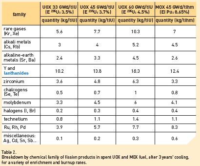
82 75
 Vitrified HL radwaste (5%) Uranium : Plutonium : Fission products : 25 kg 470 kg 5 kg (1 %) Minor actinides : (94 %) ~ 0,5 kg Minor actinides Fission products")
83 II-3. A standard UO 2 spent PWR fuel assembly (900 MWe PWR, fuel with a burnup of MW d/ t HM) has the following content Cladding & structural materials : medium level & long lived waste Plutonium Recyclable materials (95 %) Vitrified HL radwaste (5%) Uranium : Plutonium : Fission products : 25 kg 470 kg 5 kg (1 %) Minor actinides : (94 %) ~ 0,5 kg Minor actinides Fission products Relative contribution to total radiotoxicity after years Mass inventory for a standard (900 MWe) PWR spent fuel assembly with a MW d/ t HM burn-up (500 kg initial uranium content for fresh fuel) and relative contribution to total radiotoxicity after 1000 years cooling time. 76
84 Annex III Country Reports
85
86 The back-end of the fuel cycle in France: status and prospects M. Giroux a, J.-M. Grygiel a, B. Boullis b, M. Masson b, F. Storrer b a AREVA NC, France b CEA, France Abstract: France chose the closed fuel cycle at the very beginning of its nuclear program. The reactor and fuel cycle technologies have been continuously improved through R&D program and all major advances have been implemented on industrial scale in a consistent and evolutionary approach. The reprocessing and recycling facilities presently in operations are using mature industrial technologies. They are regulated through very high environmental and proliferation resistance standards. The closed fuel strategy allows extracting from irradiated fuel recoverable fissile materials (uranium and plutonium presently) which can then be recycled. Plutonium is recycled in the form of MOX fuel in PWRs. Reprocessing and MOX fuel fabrication are implemented in France on a commercial basis both for domestic and export markets. By December 2006, about t of irradiated LWR fuel and t of GCR fuel originating from France and other countries had been treated in French facilities. In addition, about 2/3 of the 2200 thm of MOX fuels fabricated in Europe have been fabricated in France. As a second benefit of this fuel strategy, the volume and radiotoxicity of the ultimate waste has been significantly lowered. The aim of further improving waste management and reducing the radiotoxic inventory was pursued in the framework of the Waste Management Act of 1991 with R&D organized along three axis: Separation and transmutation; Disposal in deep geological layers; Long-term (sub)-surface storage. Separation of long-lived elements has been assessed and demonstrated on lab scale experiments by CEA in 2005 on 13 kg HM of UO2 irradiated fuel with an average burn-up of 60 GWd/t. Development work in view of the validation of these promising results on industrial scale is ongoing in connection with the cycles envisaged for future (GENERATION IV) systems in the framework of two acts: the 2005 Energy Policy Act and the 2006 Act on the Sustainable management of radioactive materials and waste. In this respect, three main fuel cycle strategies at different stages of advancement and industrial feasibility are investigated: Separation processes based on co-extraction/co-conversion of uranium and plutonium (COEXTM) and possibly neptunium leading to the design of GENERATION III reprocessing plants which are close to near term industrial deployment and are capable of satisfying new market needs (integrated facilities with no pure plutonium separation, regional centres, high efficiency, high MOX performances both for LWRs and Fast reactor). Selective separation of long lived radionuclides from raffinate (with a focus on Am and Cm separation) based on the optimization of DIAMEX-SANEX processes for their recycling in heterogeneous mode in GENERATION IV systems. This option can be implemented with a combination of COEXTM and DIAMEX-SANEX processes. Group extraction of actinides (through GANEX processes) as a long term and challenging R&D goal for a homogeneous recycling of actinides in GENERATION IV fast systems. 79
87 1. FRENCH ENERGY POLICY AND LEGAL FRAMEWORK FOR WASTE MANAGEMENT The French Energy Policy In France the development of an ambitious nuclear power program associated with a closed fuel cycle was driven by the political will to achieve a substantial level of energy independence in a country poorly endowed in fossil fuels and having domestic uranium resources available in limited amount. The energy independence goal assigned to nuclear power has been achieved. Since the beginning of the nineties, nuclear power has been fulfilling about three-quarters of the electricity demand in France, a sizeable contribution to the decrease in energy imports (decrease of 16 billion in 2006). A key added benefit is the avoided emission of CO2 (about 126 Mt in 2006). According to the 2005 law establishing guidelines for France energy policy and security, the government makes sure that Nuclear Power provides an important share of the electricity mix. To maintain the nuclear option open after 2020, a new generation reactor must be available by 2015 on a commercial basis. In the framework of this 2005 global energy act, a research policy is also defined to sustain the development of innovative energy technologies consistently with the French climate plan aiming at reducing the emission of greenhouse gases. This roadmap includes several key steps such as: implementation and testing of a first of a kind GENERATION III (EPR) reactor so as to be able to decide for a series by 2015, R&D on future nuclear systems (GENERATION IV fission reactors, fusion reactors), new energy technologies (including hydrogen economy, innovative fuels for transport sector) and energy efficiency. The contribution of nuclear power to the French energy policy was further reinforced with the following major initiatives : In January 2006, President Chirac announced the construction by the CEA of a Generation IV prototype reactor to be completed in Establishment of an independent safety authority (its mission was defined in a new law on nuclear transparency and security enacted by the French parliament on June 13, 2006). In June 2006, a new act on the sustainable management of radioactive materials and waste was approved by the French Parliament. The act includes provision for a national plan (PNG-MDR) on radioactive materials and radioactive waste management updated on a regular basis to further define and update the R&D goals and milestones for GENERATION IV systems (see next chapter). The French nuclear power fleet: status and prospects The operating French nuclear reactor park comprises 58 PWR units owned and operated by EDF (Electricité de France). The FNR Phénix is jointly owned by CEA (Commissariat à l Energie Atomique) and EDF. The 63.5 GW(e) installed nuclear capacity allowed the generation in 2006 of approximately 430 TWh net, contributing to more than three quarters of the total electricity produced in France. 80

88 The construction of an EPR, a new reactor type, is being started at Flamanville for operation in This 1600 MWe EPR type reactor and the Finnish EPR at Olkiluoto are the two first units of a standardised new family of GENERATION III reactors, designed by AREVA NP for 60 years operation. This standardised GENERATION III reactor is designed as a highly competitive tool for electricity production. A decision for a large scale industrial deployment (series) is expected from the French utility by The first GENERATION IV prototype is to be built by Industrial implementation is expected by The following figure presents EDF vision on progressive implantation of GEN III and GEN IV reactors, according to its scenarios on future electricity demand as well as needs for older reactors replacement. 81


89 The fleet renewal scenario is based on 2 GWe/year new power capacity to be built starting from The relationship between nuclear reactors successive generations and treatment plants evolution is illustrated below. 82
90 Overview of the back-end developments in France About 1100 t of irradiated fuel are unloaded every year and transported to the AREVA NC La Hague Facility for treatment. AREVA has the capacity to reprocess up to 1700 thm/year of irradiated fuel in its La Hague facility and to market 195 t/year of MOX fuel for French and foreign customers. At La Hague, two reprocessing plants are operational: UP2 dedicated to treat French PWR fuels and UP3 initially dedicated by contract to treat foreign fuels (essentially Belgian, Dutch, German, Japanese, Swiss). French origin irradiated fuels are now also treated in UP3. All MOX fuels are now fabricated at the AREVA NC Melox plant in Marcoule. The AREVA NC Cadarache plant ceased MOX production in The back-end strategy and industrial developments are to evolve progressively according to future needs : French NPP evolution, i.e.: changes in the fuel management strategy for operating PWRs, step by step implementation of EPR units, manufacturing of driver fuel for the GENERATION IV prototype, manufacturing of minor actinides bearing fuels to be tested in this demo plant, industrial implementation by 2040 of GENERATION IV fast systems. The associated fuel cycle technology is to be selected accordingly on an evolutionary design basis so as to be adaptable to the various possible recycling strategies and emerging needs of the market place. In this respect, three main R&D lines are kept open (see Chapter 3) for the next decade : o No pure plutonium separation process based on co-extraction/co-conversion of uranium and plutonium (COEX TM ) and possibly neptunium as designed for GENERATION III reprocessing plants and which are close to near term industrial deployment. o Selective separation of long lived radionuclides from raffinate (with a focus on Am and Cm separation) based on the optimization of DIAMEX-SANEX processes for their recycling in heterogeneous mode in GENERATION IV systems. This option can also be implemented with a combination of COEX TM and DIAMEX-SANEX processes. o Group extraction of actinides (through GANEX processes) as a long term and challenging R&D goal for a homogeneous recycling of actinides in GENERATION IV fast systems. New market needs : reprocessing of foreign irradiated fuels, IAEA multinational approach of the fuel cycle (e.g. through regional centres), plant with high efficiency, adaptable to MOX reprocessing both for PWRs and Fast Reactors, integrated fuel treatment-refabrication facility with no pure plutonium separation, manufacturing of high performance MOX fuels. 83
91 The legal framework for nuclear waste management The Waste Management Act of 1991 defined the legal framework for managing HLW. It organized the R&D along axis: Separation and transmutation (with CEA and CNRS as main contributors); Disposal in deep geological layers (R&D led by ANDRA); Long-term (sub)-surface storage (R&D led by CEA). A status report assessing the most promising R&D routes was submitted to French authorities in As a result, the legal framework for the waste management in France was updated with two important laws, both enacted in 2006: The Law on nuclear transparency and security established a new independent safety authority ASN (Autorité de Sûreté Nucléaire). The ASN is chaired by a college of 5 members appointed for 6 years. It ensures the control of nuclear safety and radiation protection to protect workers, patients, the public and the environment from risks related to the use of nuclear technology. The Programme Act on the sustainable management of radioactive materials and wastes is about all types of radioactive waste (not only long lived high level waste). It defines three main principles concerning radioactive waste and substances: reduction of quantity and toxicity, interim storage of radioactive substances and ultimate waste, deep geological disposal. The law retains retrievable deep geological storage as the reference solution for long lived and high level waste. The French parliament will be consulted again by 2015 on possible designs of the disposal site. A national disposal centre might be operated by 2025 subject to Parliament authorization. The disposal in France of foreign irradiated fuel or radioactive waste is prohibited. The law defines financial arrangements for research, nuclear plants decommissioning charges, additional taxes on nuclear facilities to finance research programs. It provides also clear definitions for radioactive materials and waste and specifies that treatment is the way to reduce the volume and radiotoxicity of nuclear waste. A central point is the creation of a national management plan defining the solutions, the goals to achieve and the research actions to be launched to reach these goals. This plan is updated every three year and published (according to the law on nuclear transparency and security). The law insists on transparency and democratic control. The waste disposal managed by ANDRA Nuclear facilities are conditioning all waste according to safety authority requirements. Those originating from France can then be transferred to ANDRA for disposal, according to their specifications, in several dedicated sites. Conditioned high level and long lived wastes are stored at production sites pending the creation of a disposal site by ANDRA. ANDRA is currently operating the Soulaines disposal facility for Low and Intermediate Level Waste and the Morvilliers disposal facility for Very Low Level Waste. In 1999, ANDRA was authorized to build in the Bure area an underground research laboratory for long lived HLW and ILW disposal. 84


92 2. BACK END OF THE FUEL CYCLE IN FRANCE In France the closed fuel cycle increases the nuclear power program s sustainability as it allows the recovery of fissile materials to fuel present and future generation reactors. It furthermore provides a safe and secure management of wastes while significantly minimizing the burden left to future generations Present Status Irradiated Fuel Transportation and Interim Storage Approximately 1100 t of irradiated fuel are unloaded every year from the French reactors. After a few years of cooling down in pools at the reactor sites, irradiated fuel is shipped to the AREVA NC La Hague Facility where it is stored in pools for an additional cooling period before being reprocessed. The cumulated authorized pool capacity at the La Hague plant is about 18,000 thm. Transports of French and foreign irradiated fuel to the La Hague plant are carried out by TN international, an AREVA NC subsidiary. The company has acquired a large international experience in metal casks and concrete casks for transport and/or storage of irradiated fuel. Irradiated Fuel Transportation cask. Irradiated Fuel Storage at La Hague Plant Reprocessing In France, GCRs (Natural Uranium Graphite Gas Reactors), FBR's, PWR's and RTR's (Research and Test Reactors) were or are in operation. The irradiated fuel coming from these different types of reactors have all been reprocessed in the past 40 years in 3 reprocessing plants: UP1, UP2 and UP3. The experience gained by the French industry has benefited other countries. By the end of 2006, more than 18,000 thm of GCR fuel and approximately 22,700 thm of LWR fuel coming from France and other countries had been reprocessed. UP1 (Marcoule) The UP1 reprocessing plant (PUREX process) located in Marcoule (Rhone Valley), started civilian operations in 1965 with the reprocessing of irradiated nuclear fuel from French and 85

93 foreign GCR reactors. In 1978 the first French vitrification facility (AVM) was added to the UP1 plant to condition HLW waste. By 1997 end, GCR reprocessing had ended in UP1 and the plant was shut down in An Economic Interest Group for the management of all the decommissioning operations was set up by CEA, AREVA NC and EDF. The closing down phase including advanced rinsing and removal of nuclear material was completed in 2002 and total dismantling funded mainly by EDF and CEA should be accomplished within circa 30 years. AREVA NC La Hague (UP2 UP3 plants) In 1966, a second reprocessing plant referred to as UP2-400 was commissioned in France, at the La Hague site (in Normandy). With a 400 thm/year initial capacity, this plant was operated to reprocess GCR fuel. In 1976 a new head-end (High Activity Oxyde, HAO) was added to UP2 in order to reprocess LWR fuel. In 1994, UP2-400 was upgraded to meet the French growing reprocessing needs and renamed UP In 1989, an additional plant named UP3 was commissioned to reprocess foreign origin irradiated fuel. The two presently operating La Hague plants are based on the PUREX process. The AREVA NC La Hague Reprocessing site. Following a public inquiry in May 2000, AREVA NC was authorised in three decrees dated January 10, 2003, to modify the operating conditions of UP2 800 and UP3. The individual capacity of each of the two plants was raised to 1000 t per year of heavy metal (U or Pu), with the total capacity of the two plants being limited to 1700 t. La Hague historical production data About 22,700 thm had been treated at AREVA NC La Hague by 2006 end (close to 12,700 thm originating from France and more than 10,000 thm of foreign irradiated fuel). 86

94 The next table details the status of irradiated fuels and materials received at La Hague by country of origin. Only 4% of the irradiated fuels and materials in pools by 2005 end are of foreign origin. La Hague occupational exposure For the last twenty years La Hague average occupational exposure has remained below natural background. Its 2005 level was msv/per employee. As a matter of comparison, the European Union limit is 20 msv per employee per year. 87
95 msv/man/year AREVA NC (2005: msv/man/yr) SUBCONTRACTORS (2005: msv/man/yr) BACKGROUND RADIATION ,119 0,03 La Hague impact on the local population The added dose on the most exposed population has been averaging about 0.01 msv per person per year for the last twenty years. As a matter of comparison, the European Union limit is 1 msv per person per year. 88

96 1 msv 0,10 0,09 0,08 0,07 0,06 0,05 0,04 0,03 Added doses (msv/an) Added doses: gas Added doses: liquid Impact of releases on the reference group of inhabitants of Digulleville 0,02 0,02 0,01 0, Recycling Plutonium recycling EDF recycles PWRs plutonium from the reprocessing of its irradiated fuel in 20 of its 900 MWe. Gravelines : B3 & B4 (1989), B1(1997), B2 (1998) Chinon : B4 (1998), B3 & B2 (1999), B1 (2000) Reactors technically capable for moxification (in blue) Gravelines C5 & C6 Blayais 3 & 4 Cruas 1 & 4 Reactors loaded with MOX (in orange) St-Laurent : B1 (1987), B2 (1988) Dampierre : 1 (1990), 2 (1993), 3 & 4 (1998) Le Blayais : 2 (1994), 1 (1997) Tricastin : 2 & 3 (1996), 1 & 4 (1997) 89

97 As of December 31st 2006, more than 2700 MOX fuel assemblies had been delivered to EDF. MOX fuel loaded in French PWR's is licensed for an average burn-up of about 40 GWd/tHM. In order to further enhance the availability and performance of reactors in operation, studies have been undertaken to further improve MOX fuel and its in core management. The objective is to implement the MOX parity management ensuring that MOX fuel delivers an energy equivalent to the UO2 fuel with a 3.7% enrichment in uranium 235. The first plutonium recycling in France took place in the Rapsodie research reactor about forty years ago, the fuel being manufactured since 1961 at the Cadarache Plant located in the southeast of France. This plant then fabricated the MOX fuel for Phenix and Superphenix fast reactors. In 1987, the Cadarache plant was upgraded to produce MOX fuel assemblies for LWR. Its 40 thm/y capacity was reached by the mid nineties. The AREVA NC Cadarache site ceased its commercial MOX production in July 2003 and is currently conditioning the waste from its former operations, before being dismantled. All MOX fuel is now fabricated at the AREVA NC MELOX plant located in Marcoule (Gard region). This plant was commissioned in March 1995 reaching in 1997, its first nominal licensed capacity of 100 thm/year. In September 2003, MELOX was authorized to increase its annual production level to 145 thm. In September 2004, AREVA NC submitted a request to the French Competent Authorities to increase its production capacity from 145 to 195 HMt/year. License was granted in April Over 1,100 thm of MOX fuel had been fabricated by 2006 end. View of the MELOX plant. RepU recycling Reprocessed uranium (RepU) recycling has been demonstrated in two units at the Cruas NPP since the mid eighties. The RepU inventory being a strategic resource, its increased utilization is an option considered by EDF taking into account the evolution of the natural uranium market. Reprocessed uranium is converted in COMURHEX plants at Pierrelatte, either to U3O8 for interim storage, or to UF6 for re-enrichment in centrifugation facilities. The enriched UF6 is then converted in the FBFC Romans plant (capacity 150 thm/y) to UO2 fuel Conclusion By 2006 end, about 22,700 tons had been processed at the AREVA NC La Hague plant and more than 1100 thm of MOX fuel assemblies had been fabricated at AREVA NC MELOX Plant with minimum impact on public health and the environment: 90


98 The occupational exposure at La Hague and MELOX is one or two orders of magnitude below the European Union limit of 20 msv per employee per year. The radiological impact on the environment falls well under 1% of the European Union limit for the general public of 1 msv per year. There had been no safety events at either of the two facilities above level 2 (incident) of the International Nuclear Event Scale which ranges from 0 (no safety significance) to 7 (major accident). There is regular extensive third-party verified monitoring of the surrounding environment Improvements and prospects FOR industrial developments Existing plant improvement UP2 and UP3 plant operations are based on the PUREX process. Their construction was decided in the seventies and massive production took place in the nineties, during which time plant operations were continuously improved. The uranium and plutonium separations factor has now reached 99.88%, leaving in the vitrified matrix only about one gram of plutonium for each kilo recovered, and contributing to the minimization of radiotoxicity and waste volume. Vitrification AREVA benefits from more than 20 years of industrial experience using hot crucible melter technology in three different vitrification facilities: AVM in Marcoule, R7 and T7 (respectively commissioned in 1989 and 1992) at the La Hague site. By the end of 2005, AREVA NC s vitrification facilities had produced over 15,000 canisters of vitrified HLW. Current two step Vitrification process: About 22,700 thm of irradiated fuel reprocessed in La Hague Pouring glass fabricated by the current two step process into a container. After fifteen years of operation in R7 and T7, each with a nominal capacity of more than 550 glass canisters per year, the life time of the melters exceeds design basis values by a factor of two. The feedback from active operation and R&D results has led to further improve the process in areas such as glass characteristics, associated technologies, operation and maintenance. 91


99 To broaden the performance range of the vitrification process, CEA and AREVA, with its engineering subsidiary SGN, have developed the use of the cold crucible melter (CCM) technology. It leads to a virtually unlimited equipment service life and allows a greater flexibility with respect to waste composition. The high specific power directly transferred to the melt by induction helps in adjusting glass temperatures. Direct-induction cold crucible vitrification Direct-induction melting consists in placing the glass that is to be heated inside an alternating electromagnetic field, generated by an inductor. This field causes induced currents, which dissipate energy through joule effect inside the material resulting in its melting. With direct induction, the point is to heat the material to be melted, directly, without heating the crucible. The latter, on the contrary, is cooled by water circulation, and sectorized, to ensure relative transparency to the electromagnetic field. Cold crucible developed for AREVA industrial application at La Hague. Compared with the current process, the cold-crucible melting technology brings major benefits. First of all, cooling the melting furnace allows a thin layer of solidified glass to form, protecting the crucible and precluding corrosion from the molten glass. Second, heating by direct induction within the molten glass bath allows higher fabrication temperatures to be achieved, thus enabling design of novel, higher-performance waste-confinement matrices. 92
, Pouring glass station, Gas treatment operation To increase throughput and flexibility (with respect to liquid feed as well as solid feed acceptance criteria), the ACCM (advanced CCM) variant")
100 The technological test platform set up in 2001 by CEA and AREVA to demonstrate the feasibility of the advanced cold crucible technology ( Cold crucible (diameter 1.1 m), Pouring glass station, Gas treatment operation To increase throughput and flexibility (with respect to liquid feed as well as solid feed acceptance criteria), the ACCM (advanced CCM) variant was developed. This design allows (in a single step process) to directly feed the melter with solid or liquid waste flow, while improving the glass throughput capacity. Hulls and end fittings compaction (ACC and ECC units) The compaction facility (ACC, Atelier de Compaction des Coques), which started operation in 2002, allows a four-fold reduction in waste volume resulting from fuel reprocessing. Structural parts of fuel elements (hulls and end-fittings) with long-lived radio-nuclides, which were conditioned in grout until 1995, are now compacted and packaged in universal canisters also used for vitrified waste. Each canister is filled with 5 to 7 discs according to their thickness, in order to produce less than 1.5 Universal Canister per ton of reprocessed irradiated fuel. Up to 2,400 canisters yearly can be produced at the ACC. The Universal Canisters once produced in the compaction facility (ACC) are sent to an interim storage facility (ECC, Entreposage des Coques Compactées) before final shipment to the customer s designated facility. New Effluent Management Thanks to the extraction process performance levels, the volume of low-and medium activity effluents produced are much below the estimates made during the facilities' design phase. The new management allows better sorting of the effluents, based on their radioactive and chemical content. After evaporation, concentrates containing most of the effluents' radioactivity are now vitrified with high-activity wastes without increasing the volume of glass produced (see next Table and Figure). Thanks to this process, there is no more ILW to bitumenize prior effluent discharge to the sea, as was previously the case. 93

101 Percentage of activity Reprocessing by-product activity α β γ (except tritium) Vitrified waste Hulls and end-fittings Total process waste Technological waste Broadening the range of operation in existing plants The reference fuel considered for the design and start-up of the UP3 and UP2-800 plants was uranium oxide fuel initially enriched to 3.25% in 235 U, with a burn-up of 33 GWd/t and cooled for 3 years. However, right from the very beginning of the La Hague site, AREVA NC was authorised, based on supporting studies, to use the HAO facility to reprocess other types of fuels. The UP3 and UP2-800 plants today process PWR and BWR fuels initially enriched to 3.7% in U235, with burn-up reaching 45 GWd/t, cooled for a minimal 4-year period. The general trend is toward higher burn-ups and subsequent higher initial enrichments (up to 4.5 % or more). MOX and RTR fuel reprocessing campaigns have been performed demonstrating the flexibility of the La Hague plant and thus its technical ability to reprocess new generations of irradiated fuel without significant modifications. 94

102 2.3. Treatment/Recycling plant evolution The existing workshops at La Hague (commissioned in 1990) have been designed to operate for at least forty years. With operational and technical improvements taking place on a continuous basis, they are expected to be operating, with flexibility as required, until around 2040 when GEN IV facilities (reactors and treatment facilities with advanced separation capabilities) should come on line. In the meantime, an integrated treatment/recycling plant could be built if requested by the market. Such a scheme considering the recycling of recovered fissile materials in MOX fuel (according to needs including in fast reactors) would rely as a first step on the COEX process that can be implemented rapidly, and later on upgraded with other advanced processes. A COEX GEN III Plants is an integrated plant (in line fuel treatment/refabrication) with no separated plutonium (U and Pu co-extracted and kept together in solution all along the process), on line measurement of fissile materials inventory, and advanced safeguards devices. Going back to France (see section: the French nuclear power fleet: status and perspective of chapter 1), the evolution of a back-end scheme and associated technologies shall be consistent and synchronized with the evolution of reactor concepts and associated nuclear fuel cycles. Studies are presently undertaken to assess the capability and the interest of using the existing treatment and recycling sites, including La Hague, to host demonstration facilities to investigate advanced actinides separation options as required by the 2006 Act on the Sustainable management of radioactive materials and waste. Preliminary work has been initiated to investigate the possibility for two fuel fabrication facilities to be associated with the GENERATION IV reactor prototype: Manufacturing of prototype driver fuel (10 t/year capacity); Micro-pilot manufacturing of minor actinides bearing fuels for test irradiation (a few tenth of kg/year capacity). The fuel cycle workshops associated with the French GENERATION IV prototype: 95
103 3. Research and development for the future In France, the R&D on treatment processes is undertaken according to the national plan on radioactive materials and radioactive waste management updated every three years by Parliament according to the 2006 Act on sustainable management of radioactive materials and waste (see 1). This plan specifies a step by step R&D programme based on 3 routes (as an extension of the roadmap already defined in the framework of the 1991 waste management Act) which complement each other: Act 1: Partitioning and transmutation with the following key milestones: 2012: assessment of GENERATION IV reactor and fuel cycle technologies and of their industrial feasibility 2020: operation of a prototype fast reactor Act 2: Geological disposal for ultimate HLW with the following key milestones: 2015: expected authorization for construction of the disposal. 2025: target date to operate the disposal. Act 3: R&D on very long term interim storage. The R&D on treatment processes refers to axe 1. The fuel cycle scenarios are developed in an evolutionary approach so as to be consistent with changes progressively to be implemented in the French nuclear power park: Extension of fuel burn-up in PWRs; Extension of plant life time; Parity of UOX and MOX fuels burn up; Step by step shutdown of old facilities and renewal of the French reactor fleet with GEN-3 PWRs (such as EPR reactors); Introduction of GEN-IV on the long run (by 2040) in a multi-strata scenario. In that respect, three main fuel cycle strategies are investigated by the CEA in order to provide technical (and economically acceptable) solutions that will ease the decision taking process when appropriate: Optimization of U and Pu recycling strategy using existing PWRs and EPR units to be implemented in France NPP as a first step, co-management of U, Pu and possibly Np in GENERATION IV fast reactors as a second step. Feasibility of minor actinides (MA) homogeneous recycling in driver fuels of GENERATION IV reactors (with a low content of MA, typically 3%). Feasibility of MA heterogeneous recycling in about one third of the nuclear power park with a higher content of MA (typically 30%) in MOX blanket assemblies of GENERATION IV fast reactors or as target in Accelerator Driven Systems. 96
104 These three paths are symbolized in the figure below: Since the early nineties CEA has been undertaking research and development studies on the separation (recovery) of the minor actinides (MA) i.e. neptunium (Np), americium (Am) and curium (Cm)-contained in the irradiated fuel. The reference strategy for separating these elements from the irradiated fuel is based on an adaptation of the PUREX process for the separation of Np and the development of new liquid-liquid solvent extraction processes DIAMEX and SANEX for the others (Am, Cm). The scientific feasibility of these processes has been performed at lab-scale within year 2005 in ATALANTE (in cells equipped with pulsed columns, mixed-settlers, centrifugal contactors and Couette Effect columns), starting from about 13 kg of genuine uranium oxide irradiated fuel at around 60 GWd/t. The next step is to further assess the implementation on industrial scale of these three types of processes obviously at different stage of development today: (a) Separation processes based on co-extraction/co-conversion of uranium and plutonium (COEX TM ) and possibly neptunium are already leading to the design of GENERATION III reprocessing plants which are close to near term industrial deployment and are capable of satisfying new market needs (no pure plutonium separated, higher throughput, high MOX performances both for LWRs and Fast Reactors). (b) Selective separation of long lived radionuclides from raffinate (with a focus on Am and Cm separation) based on the optimization of DIAMEX-SANEX processes for their recycling in heterogeneous mode in GENERATION IV systems. This option (b) can be implemented in combination with COEX TM process option a). 97
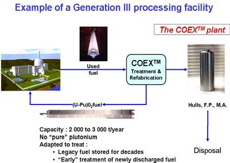

105 98


106 c) Group extraction of actinides as an alternative fuel cycle strategy to allow for the homogeneous recycling of actinides in GENERATION IV fast systems. The reference process, called GANEX, is an adaptation of the DIAMEX-SANEX flowsheet and will be tested on genuine solution in First oxalic co-precipitation of (U,Np,Pu,Am) tested in CEA Atalante facility. The GANEX process flow sheet. 99


107 In that respect, the key milestones for the three routes (COEX, DIAMEX-SANEX, GANEX) are: lab-scale process demonstration by Technical feasibility of the envisaged three processes to be assessed by 2012 and selection of technologies to be tested for industrial scale development with the construction of two pilot plants : o One dedicated to the manufacturing of the driver fuel of the GEN-IV prototype plant to be built by 2020 by CEA (possibly based on the COEX TM technology) o One dedicated to the production of fuel assemblies containing minor actinides which could be tested under irradiation in the MONJU fast reactor and in the French GEN-IV prototype reactor. In the long run, the goal is to have a technology validated for industrial scale deployment of GEN-IV fast reactors by
108 Spent fuel treatment options and application An Indian perspective P.K. Dey Bhabha Atomic Research Centre, Trombay, Mubai, India Abstract: India has opted for a three stage nuclear power programme based on a closed fuel cycle approach for the development of the nuclear energy. Currently India has a total of 16 operating power reactors comprising 14 PHWRs and 2 BWRs with a total power capacity of 3.9 GW. The energy demand is growing by leaps and bounds and the per capita energy requirement is expected to cross 5000 KWh by the middle of the century. For the next 20 years, India will have to rely mainly on thermal and hydroelectric power. However in the long run, nuclear energy can play a vital role in the future energy mix since our coal reserve is finite and hydroelectric power addition can only be moderate. Reprocessing and recycling of the fissile and fertile components back into appropriate reactor systems is an integral part of the Indian nuclear energy programme. The limited natural uranium resources will be used up in the first phase and the vast resources of thorium is expected to be employed for sustained electricity generation in the third phase. The plutonium recovered from the first phase will serve as a link between the two phases where it will be deployed in fast reactors for enhancing the fissile inventory to launch the thorium fuel cycle. The choice of the reprocessing and plutonium recycle option has endowed the nuclear power program with a variety of midcourse options in both uranium and thorium fuel cycle. This spent fuel reprocessing programme was launched way back in 1964 with the commissioning of the plant at Tromby for the reprocessing of research reactor spent fuel. This was followed by setting up of another plant in 1975 at Tarapur for the reprocessing of spent fuel from PHWRs. The next plant for the reprocessing of power reactor spent fuel was commissioned in 1998 at Kalpakkam to meet the growing requirements of the nuclear energy programme. India is about to step up its nuclear energy production and is ready to launch the second stage activities by setting up Fast Breeder Reactors. Reprocessing facilities are being augmented to meet the fuel requirements of the second stage. Process developments are in progress to meet the reprocessing challenges of the fast reactor fuel cycle. For India, the building up of fissile material inventory at a fast pace is a prerequisite for the early introduction of thorium in the power programme. To meet the challenges of a thorium fuel cycle, reprocessing of irradiated thorium for 233 U recovery was initiated almost from the beginning. After pilot scale studies in the early seventies, an engineering facility started operating in this domain for the recovery of 233 U from thoria irradiated in research reactors using Thorex process. An engineering facility for the recovery of 233 U from thoria rods irradiated in PHWRs during the initial flux flattening is expected to be in operation soon. As a predecessor to the third stage reactor for utilisation of thorium, an Advanced Heavy Water Reactor(AHWR) employing both (Th-Pu)O 2 and (Th- 233 U)O 2 fuels in one cluster is being inducted into the nuclear power programme. Reprocessing of the spent fuel from this reactor will pose many challenges and will necessitate the development of a flow sheet for the recovery of three components viz. U,Th and Pu. Currently fuel cycle studies are initiated to develop suitable flow sheets to close the AHWR fuel cycle. Introduction India is in a unique situation as far as its nuclear resources are concerned. Hence a three stage programme was formulated in the middle of the last century to exploit the full energy potential of its resources 1. The first stage utilizes the limited natural uranium resources for both power production and also for the conversion of uranium to plutonium. The Plutonium produced in the first stage will form the fuel for the second stage where it will be used in fast breeder reactors to produce power and to enhance the fissile inventory necessary for launching the third stage thorium based power reactors. Fig. 1. Shows the basic outline of the Indian nuclear energy programme. Reprocessing and recycling of both fissile and fertile components back into appropriate reactor systems is an integral part of this strategy. This programme is conceived half a century back and is valid even today. 101
109 Natural Uranium PHWR 10 GWe, 40 y Electricity Th Depleted U Pu Pu FUELLED FAST BREEDERS 530 GWe, 100 y Electricity Th 150,000 GWey Pu 233 U 233 U FUELLED BREEDERS Electricity 233 U STAGE 1 STAGE 2 STAGE 3 Fig. 1. Three Stage Indian Nuclear Energy Programme. The first stage of the nuclear power programme, comprising setting up of Pressurised Heavy Water Reactors (PHWRs) and associated fuel cycle facilities, is already in the commercial domain. Sixteen power reactors ( 2 BWRs + 14 PHWRs ) are operating and four PHWRs of 220 MWe rating are under construction. The second stage envisages the setting up of Fast Breeder Reactors (FBRs) backed by reprocessing plants and plutonium-based fuel fabrication plants. A higher power-generating base through Fast Breeder Reactors is also needed to establish the use of thorium on a large scale in the third stage of our programme. A 40 MWt Fast Breeder Test Reactor (FBTR) has been operating at the Indira Gandhi Centre for Atomic Research (IGCAR), Kalpakkam, since attaining first criticality on 18 October FBTR uses a unique and indigenously developed mixed uranium carbide-plutonium carbide fuel, which has functioned extremely well up to the current burn up of about MWd/t. The FBTR has provided valuable experience with liquid metal Fast Breeder Reactor technology and the confidence to set up a 500 MWe Prototype Fast Breeder Reactor (PFBR). The PFBR design is now ready and, with several full-scale components already manufactured by Indian industry, is well poised for start of construction. Project activities are already in progress at Kalpakkam near Chennai. The third stage will be based on the thorium-uranium-233 cycle. Uranium-233 is obtained by irradiation of thorium in PHWRs and FBRs. An Advanced Heavy Water Reactor (AHWR) is being developed at Bhabha Atomic Research Centre (BARC) to expedite transition to thorium-based systems. The reactor physics design of AHWR is tuned to generate about 75% power from thorium. In parallel with the indigenous self-reliant three-stage programme, Light Water Reactors are also being inducted to boost the nuclear power production. The ongoing construction of two 1000 MWe units at Kudankulam in technical cooperation with the Russian Federation is a step in this direction. Table 1 shows the power reactor programme. 102
110 Table 1. Power reactor programme POWER REACTORS Operating Reactors Nos x MWe Total MWe BWR 2 x PHWRs 1 x x x x 540 Reactor Types under Planning/Construction PHWRs 4 x PWR 2 x 1000 PFBR 1 x 500 AHWR 1 x In the Indian context, PHWRs are the main stay of the nuclear energy programme. The spent fuel generation from a PHWR at an average burnup of 6600 MWd/t for a total 1 GW(e).Y power is ~166 THM. For the same power output the spent fuel output form a PWR with an average burnup of MWd/t is ~33 THM. The amount of minor actinide generation is more with the PWR where as the long lived fission product generation is comparable. The unused uranium and the generated Pu are larger in the case of PHWR. Thus a recycle strategy is required to extract maximum energy form the available uranium. Pu can be best utilised in fast reactors and will produce much lesser amount of minor actinides as almost all the actinides fission under a fast neutron spectrum. Use of Pu-U MOX irradiated in a thermal spectrum will enhance the minor actinide production and hence increase the radiological hazard. The minor actinide generation is several orders less when Th is used as the fertile material. Pu along with Th can be used as a fuel on an interim basis for power production till the design optimisation of fast reactors are finalised. This has the dual advantage of power production and increasing the fissile inventory. Electricity demand in India is increasing rapidly with the industrial growth and is expected to increase by several folds in the coming decades. A reasonable target of generating about 8000 billion kwh per year by 2052 from the current level of 600 billion kwh per year is set and is to be achieved by judicious deployment of the available resources. Even though the conventional resources will continue to dominate, nuclear energy has to play a vital role in this energy mix as our conventional resources alone may not be able to sustain the energy growth. Status of Indian Fuel Reprocessing 2,3 Reprocessing started in India in the early days of the nuclear energy programme based on indigenous efforts. At present, India has three reprocessing plants to extract plutonium from spent fuel, the first Plutonium Plant at Trombay has a capacity to reprocess 60 tons of research reactor spent fuel per year, the second and third plants at Tarapur and Kalpakkam each having a capacity to reprocess 100 tons of power reactor spent fuel per year. The 103
111 reprocessing capacity is being augmented in a phased manner to cater to the needs of the different reactor systems as per the transition of the stages. Purex Process As early as 1964 India ventured into this technology based entirely on indigenous efforts which was till then available with only a select few countries. For the head end treatment, chemical dejacketting was followed by dissolution of the fuel in concentrated nitric acid under reflux conditions. The PUREX process comprised a decontamination cycle, a partition cycle and two separate parallel cycles for the purification of uranium and plutonium. The reductant used in the partitioning stage was ferrous sulphamate solution in nitric acid medium. The final purification of plutonium nitrate solution was by ion exchange. Being first of its kind, the design philosophy was completely based on direct maintenance concept. The successful operation of the plant also helped in providing plutonium for pursuing various programmes of nuclear research and development. This plant had to undergo many modifications during its lifetime and it was finally decided to decommission this plant to increase its life. The requirement to treat power reactor spent fuel necessitated the setting up of another reprocessing facility to treat zircaloy clad spent fuel. The commercially available BWR fuel chopper was adapted to suit the PHWR spent fuel. Uranous nitrate stabilised by hydrazine as the reductant for partitioning was introduced for the first time in this plant. Instead of the separate co-decontamination and partitioning cycle a combined co-decontamination cum partitioning cycle was introduced. The ion exchange purification of plutonium was replaced with a 20% TBP solvent extraction/stripping cycle to cater to the needs of higher Pu throughput. Austenitic stainless steel variety 304 L was the choice available at that point of time. Except for the head-end, which had provision for remote maintenance of in-cell equipment, the concept used for the rest of the plant was that of direct maintenance. Several campaigns of reprocessing were carried out under international safeguards also at this facility which provided valuable experience in material accounting practices to meet the international standards. This plant also provided experience in the design of appropriate packages and safe in-land transportation of spent fuels which is a vital input for locating the reprocessing facilities. Since 1975 there have been safe shipments of spent fuel involving thousands of kilometers by rail and road. With the advancements in the nuclear energy power programme, another reprocessing plant was setup at Kalpakkam to augment the capacity. Fabrication, installation and commissioning of the plant was carried out with the involvement of industries. This step was necessitated to create the necessary infrastructure to keep pace with the advancements in the nuclear power programme. Around 40 years of experience in the spent fuel reprocessing based on PUREX process has given the confidence that this technology can be successfully employed for the recovery of both U and Pu with yield exceeding 99.5%. The gaseous and liquid effluents undergo thorough processing prior to the discharge to the environment. Over the years, improved practices has brought down the environmental discharges to much lower levels than the stipulated values. The materials for reprocessing plant have to ensure resistance against intergranular corrosion in nitric acid at different concentrations and elevated temperatures. Currently the nitric acid grade stainless steel produced in India for reprocessing applications has already achieved a corrosion resistance rate as low as a value as 10 mpy 104
112 Thorex Process Most of the experience in THOREX domain has come from the recovery of low amounts of 233 U bred in irradiated ThO 2 from CIRUS research reactor. An engineering scale facility is in operation at Trombay for the processing and recovery of 233 U from CIRUS and Dhruva irradiated thorium fuel rods. The modifications felt necessary from the pilot plant have been incorporated in the design of equipment and in the choice of process flowsheets. Specially designed CALMIX mixer settlers have been chosen as contactor equipment. The scrub section has been extended sufficiently to provide for adequate scrubbing of thorium from the uranium loaded organic. The tail-end purification of 233 U is done by cation exchange process. The thorium oxalate precipitation and separation route is being installed as laboratory back-up procedure for final purification of 233 U. Further studies are required to deal with the reprocessing of irradiated ThO 2 bundles used in the initial flux flattening of PHWRs. These bundles had contributed to the power generation during its stay in the reactor and the 233 U bred had undergone fission to significant extent. The radioactivity from fission products will be considerable and the 232 U concentrations are also expected to be much higher. This will necessitate fine tuning of some of the process parameters. Fast Reactor Spent Fuel Reprocessing 4 Fast reactor spent fuel reprocessing studies are vital for the closing of fuel cycle and R&D studies were initiated almost two decades back. A pilot plant, the Lead Mini Cell (LMC), for demonstrating fast reactor fuel reprocessing had been setup for the reprocessing of spent mixed carbide fuel from fast breeder test reactor. Recently in LMC, mixed carbide fuel upto 100 GWd/t burnup with short cooling period had been successfully reprocessed for the first time. The results of the LMC reprocessing campaigns were extremely encouraging. It has given valuable inputs to undertake the design of chopper, dissolver and centrifugal extractors for an engineering scale fast reactor reprocessing plant. Lot of experience has been gained in the remote operation and maintenance of hot cell equipment using incell gadgets. The successful reprocessing of 100GWd/t burnup short cooled fuel through the PUREX process has proved the credentials of the method even for the reprocessing of fast reactor fuels. Research & Development in Fuel Cycle Activities U-Pu fuel Cycle Partitioning and Transmutation (P&T) has been in the focus for the past few decades as a means of reducing the radiological hazard. The radiological hazard is mainly confined to the spent fuel and the HLW generated during reprocessing of the spent fuel. In the initial few hundred years fission products 137 Cs and 90 Sr are the major contributors to the radiological hazard. But beyond 1000 years actinides Np, Am and Cm and long lived fission products like 129 I, 135 Cs, 99 Tc etc predominate the scenario. P&T strategy envisages the partitioning of these nuclides generally left out in the waste and transmuting them into short lived nuclides or fission products which can completely decay under 1000 years, the safe limit of the present repositories. Purex process modifications are sufficient to take care of the two most important long lived fission products viz. 99 Tc and 129 I. Iodine is converted to vapour state during dissolution and is 105
113 trapped in suitable sorbents and the dissolved 99 Tc can be separated from the loaded organic by using a suitable scrub. Process to recover the Tc from the solid residue is being explored. In the Indian context, a 0.2 M CMPO diluted in 1.2 M TBP in dodecane was employed in the development of process flow sheet for actinide partitioning from the PUREX HAW of PHWR origin 5. A 30% TBP pre-contact to the HAW was found to preserve the capacity of CMPO for the less extractable Am and Cm 6. In order to take care of the acid reflux and also to reduce the waste volume generation during back wash of Np,Pu and trivalent ions, a reagent mixture containing 0.4 M N 2 H MHCHO +0.1 M citric acid was developed 7,8. This reagent can strip all the TRU elements along with rare earths in a small volume. Studies using alternate reagents line DMDBTDMA 9, TEHDGA 10, etc. are in progress to evaluate their performance prior to finalising the flowsheet. Cs removal from the actinide depleted CMPO raffinate was tested with granulated AMP 11. Separation of Ce from Am by electro-oxidation of Ce followed by its extraction has been developed 12. Extraction chromatographic separation of 147 Pm and 90 Y were also achieved as a byproduct of this campaign 13,14. Fast Reactor Fuel Cycle Facility, an integrated facility, is proposed to be built at Kalpakkam, Tamilnadu to cater to the reload fuel requirement of Prototype Fast Breeder Reactor being setup at that centre. This facility will comprise of a spent fuel reprocessing plant, Waste management plant, fuel fabrication plant, reprocessed uranium oxide plant, core assembly plant and common services and utilities catering to all plants in this facility. The reprocessing plant is designed to reprocess the irradiated fuel subassemblies and radial blanket subassemblies from PFBR and deliver PuO 2 and U 3 O 8 powder for fuel fabrication plant and reprocessed uranium oxide to reprocessed uranium oxide plant. The reprocessing is planned in such a way that the out of core inventory of the fissile material is kept to a minimum. This reprocessing facility will also cater to the reprocessing of pellet rejects from the fabrication plants. The solid and liquid wastes generated in the reprocessing plant will be treated in the waste management plant. In processing high burn-up, short cooled fast reactor fuels, multiple recycle of Pu would pose problems in the process and in the handling of the final products due to alpha, gamma and neutron radiations arising from increasing amounts of 238 Pu, 241 Am and Cm isotopes. The radiolytic degradtion of TBP may also be severe. Under these circumstances pyroprocesses may become an alternative to aqueous reprocessing. A proliferation resistant regime is one in which all the actinide produced in the spent fuel is recycled back to the reactor with much lower decontamination from fission products. This can be best achieved by employing pyrometallurgical processes. This has resulted in renewed interest in non aqueous route especially in the molten salt electrolysis. Even though the closing of the fuel cycle has been demonstrated on a small scale, a lot of research and development activities are needed to make it a commercially viable process. In the Indian Context deployment of metallic fueled fast reactors are ideally suited to support the energy requirement. Pyro-processes are more apt for treating the high burnup fuels with short cooling. All-round efforts are in progress to develop this technology into a matured process by the time the metallic fuelled reactors become a reality 15. Fig. 2 is a schematic of the advanced fuel cycle Th- 233 U Fuel Cycle The (n,2n) reactions encountered during the irradiation of thorium lead to the formation of long lived 231 Pa and relatively short lived (68.9 yrs.) 232 U with its hard beta gamma emitting 106
114 daughter products. Thus the 233 U produced in the reactor is contaminated with 232 U and the level of contamination depends on the isotopic composition of initial thorium fuel, the burn up and the neutron spectrum encountered in the reactor. The radioactive contamination from 232 U in the separated 233 U product and from 229 Th and 228 Th in the separated thorium product will have to be taken into consideration while handling these products. 231 Pa is the main longlived actinide that needs to be assessed for its long-term environmental impact in THOREX High Level Waste. A facility named the Power Reactor Thoria Reprocessing Facility (PRTRF) is being constructed at Trombay for processing the irradiated Thoria bundles from PHWR, to separate 233 U. This facility would provide rich experience as several new technologies are being adopted in the flowsheet. The process flow sheet involves dismantling of the spent fuel bundle end plates for the first time by using a 150 Watt NdYAG LASER mounted on CNC. Individual pin from the bundle will be chopped into pieces in one stroke and fed into dissolver for leaching with nitric acid in the presence of sodium fluoride-aluminium nitrate. 233 U will then be selectively extracted using 5% TBP/NPH in CALMIX contactors and further purified by ion exchange prior to conversion to oxide. LMFBRs LMFBRs ADVANCD FUEL CYCLE Fuel Fabrication PYRO I Tc Np U+Pu U PHWRs Spent Fuel An/ Ln Separation Advanced PUREX Process HLLW Partitioning Hull Pieces FPs ADSS PYRO Value Recovery Repository Fig. 2. Schematic of Advanced Fuel Cycle. AHWR Spent Fuel Reprocessing 16,17 Advanced heavy water reactor(ahwr) designed with the dual objectives of exploiting the expertise acquired from the PHWR operation and to gain all-round experience in the thorium 107

115 fuel cycle. This reactor will serve as a predecessor to the third stage reactors which will be based on thorium- 233 U fuel cycle and will provide the much needed vital information to initiate this fuel cycle. AHWR, a hybrid reactor, is an innovative reactor design meeting the dual objective of interim utilisation of the PHWR produced Pu and introducing the available Th resources to enhance the fissile inventory. This reactor uses Th-Pu fuel bundles along with Th- 233 U fuel bundles. The arrangement of pins in the fuel cluster is shown in Fig. 3. The cluster has 54 fuel pins arranged in 3 concentric rings around a central rod. The 24 fuel pins in the outer ring have (Th Pu)O 2 as fuel and the 30 fuel pins in the inner and intermediate rings have (Th 233 U)O 2 as fuel. The innermost 12 pins have a 233 U content of 3.0 wt.% and the middle 18 pins have 3.75 wt.% 233U. The outer ring of (Th Pu)O 2 pins contain 3.25 wt.% of total plutonium, of which the lower half of the active fuel has 4.0% Pu and the upper part has 2.5% Pu. The fuel pin consists of fuel pellets confined in a Zircaloy-2 clad tube. The central rod has a tubular construction with holes for direct injection of ECCS water on the fuel rods. It also contains dysprosium capsules containing dysprosium oxide in Zirconia matrix. Fig. 3. AHWR Fuel Cluster. The AHWR fuel cycle is a closed fuel cycle, envisaging recycle of both fissile 233 U and fertile thoria back to the reactor. The currently envisaged fuel cycle time is eight years. This comprises four years for in-reactor residence time, two years for cooling, one year for reprocessing and one year for refabrication. Since the 233 U required for the reactor is to be bred in situ, the initial core and annual reload for the initial few years will consist of (Th Pu)O 2 clusters only. After reprocessing, 233 U is always associated with 232 U, whose daughter products are hard gamma emitters. The radioactivity of 232 U associated with 233 U starts increasing after separation. This poses radiation exposure problems during its transportation, handling and refabrication. Hence, it is targeted to minimize delay between separation of 233 U and its refabrication into fuel. In view of this, a co-location of the fuel cycle facility, comprising reprocessing, waste management and fuel fabrication plant with theahwr has been planned. The 233 U-based fuel needs to be fabricated in shielded facilities due to ractivity associated with 232 U. This also requires considerable enhancement of automation and remotization technologies used in fuel fabrication. The spent fuel cluster, before reprocessing, would undergo disassembly for segregation of (Th Pu)O 2 pins, (Th 233 U)O 2 pins, structural materials and burnable absorbers. The (Th 233 U)O 2 pins will require a two stream reprocessing process, i.e., separation of thorium and uranium whereas the (Th Pu)O 2 pins will 108
116 require a three stream reprocessing process, i.e., separation of thorium, uranium and plutonium. This will necessitate the integration of the well known Purex process with Thorex process in some combination. A schematic flow sheet is shown in Fig. 4 Irradiated thorium processing also needs developmental efforts for better head-end techniques for decladding and dissolution of zircaloy and stainless steel clad Thoria, corrosion resistant materials of construction, modifications in process to deal with irradiated ThO 2 -PuO 2 fuels, behaviour of 231 Pa in the process and its long term impact in waste, radiological safety in handling 233 U/ 232 U. The state of the art remote handling technology and robotics will have their maximum application because of the associated activity of 232 U daughter products. Transmutation studies with actinides and long lived fission products are being planned in the FBTR and PFBR systems. From the initial parametric studies Accelerator Driven Systems are identified as the best suited device for the transmutation of nuclides. A lot more need to be understood before designing dedicated ADS for incineration of radioactive waste on a commercial scale. In spite of all these capabilities P&T is not a substitute for geological repositories. It can only reduce the actinide burden in the HLW and is in fact a complimentary process for obtaining design and safety clearance for geological repositories. 109
117 HULLS DISMANTLING & SEGREGATION DISSOLUTION & FEED CLARIFICATION U, Pu SEPARATION FROM Th AND FISSION PRODUCTS 5%TBP FPs MOST Th SOME Pu, U Th EXTRACTION (30% TBP) HL WASTE AHWR SPENT FUEL POOL REJECTS FROM FUEL FAB. FACILITY MAIN PROCESS CYCLES Scrub U,Pu SOME Th U, Pu, Th SCRUBBING U, Pu IN-SITU/ CHEMICAL REDUCTION (U-Pu PARTITONING) U U SOLUTION STORAGE Th SOME Pu, U U, Pu Pu Th,U, Pu Th PURIFICATION (2% TBP) Pu PURIFICATION (10-20% TBP) Fig. 4. Schematic Flow Sheet for AHWR Spent Fuel Reprocessing. U U PURIFICATION (CATION EXCHANGE) U PRODUCT Pu STORAGE Th STORAGE 110
118 REFERENCES [1] ANIL KAKODKAR, "Nuclear Power in India: An Inevitable Option for Sustainable Development of a sixth Humanity", World Nuclear Association Annual Symposium, London (2002). [2] H.N. SETHNA, N. SRINIVASAN, Fuel Reprocessing Plant at Trombay, Proccedings of the Third International Conference on the Peaceful Uses of Atomic Energy, Geneva, 31 Aug 9 Sep. Vol 10, Nuclear Fuels-1. Fabrication and Reprocessing, [3] P.K. DEY AND N.K. BANSAL, Spent fuel reprocessing: A vital link in Indian nuclear power program Nuclear Engineering and Design, Volume 236, Issues 7-8, April 2006, Pages [4] R. NATARAJAN AND BALDEV RAJ, Fast Reactor Fuel Reprocessing An Indian Perspective, Proceedings of GLOBAL 2005, Paper No. IL012, Tsukuba, Japan, Oct 9-13, [5] R.R.CHITNIS, P.S.DHAMI, V.GOPALAKRISHNAN, P.K.WATTAL, A.RAMANUJAM, M.S.MURALI, J.N.MATHUR, A.K. BAURI, S. CHATTOPADHYAY, Partitioning of Actinides from High Active Waste Solution of PUREX Origin: Counter-Current Extraction Studies Using TBP and CMPO, BARC Report. BARC/200/E/031, [6] R.R.CHITNIS, P.K.WATTAL, A.RAMANUJAM, P.S.DHAMI, V.GOPALAKRISHNAN, J.N.MATHUR AND M.S.MURALI, Separation and recovery of uranium, neptunium and plutonium from high level waste using tributylphosphate : Countercurrent studies with simulate waste solution, Separation Science and Technology, 33(12),pp ,1998. [7] R.R.CHITNIS, P.K.WATTAL, A.RAMANUJAM, P.S.DHAMI, V.GOPALAKRISHNAN, A.K. BAURI AND A. BANERJEE, Recovery of actinides extracted by Truex solvent from high level waste using complexing agents: I. Batch studies, Journal of Radioanalytical and Nuclear Chemistry, 240,721(1999). [8] R.R.CHITNIS, P.K.WATTAL, A.RAMANUJAM, P.S.DHAMI, V.GOPALAKRISHNAN, A.K. BAURI AND A. BANERJEE, Recovery of actinides extracted by Truex solvent from high level waste using complexing agents: II. Countercurrent studies, Journal of Radioanalytical and Nuclear Chemistry, 240,727(1999). [9] G.R. MAHAJAN, D.R. PRABHU, V.K. MANCHANDA AND L.P. BADEKA, Substituted Malonamides as Extractants for Partitioning of Actinides from Nuclear Waste Solutions, Waste Management 18,125(1998) [10] SMITA MANOHAR, J.N.SHARMA, B.V.SHAH, P.K.WATTAL; Process Development for Bulk Separation of Trivalent Actinides and Lanthanides From Radioactive High Level Waste, Nuclear Science and Engineering (in press) [11] I.J. SINGH, P.V. ACHUTHAN, C. JANARDANAN, SAVITA JAIN, V. GOPALAKRISHNANAN AND A. RAMANUJAM, Removal of 137Cs from Actinide- Lanthanide Depleted HAW, (unpublished work). [12] C.S.KEDARI, S.S.PANDIT AND A.RAMANUJAM, Insitu electro-oxidation and liquid-liquid extraction of cerium(iv) from nitric acid medium using tributylphosphate and 2-ethylhexyl hydrogen 2-ethylhexyl phosphonate, Journal of Radioanalytical and Nuclear Chemistry, Vol. 222, Nos.1-2, , [13] A. RAMANUJAM, P.V. ACHUTHAN, P.S. DHAMI, V. GOPALAKRISHNAN, R. KANNAN, AND J.N. MATHUR, Extraction chromatographic Separation of Promethium from High Active Waste Solutions of PUREX Origin, Solvent Extraction and Ion Exchange, 13,301(1995). 111
119 [14] VENKATESH, M.; PANDEY, U.; DHAMI, P.S.; KANNAN, R.; ACHUTHAN, P.V.; CHITNIS, R.R. GOPALAKRISHNAN, V.; BANERJEE, S.; SAMUEL, G.; PILLAI, M.R.A., AND RAMANUJAM, A. Complexation studies with 90Y from a novel 90Sr- 90Y generator. Radiochem. Acta., 89, 413,2000,. [15] P.K. MOHAPATRA, R.M. SAWANT, B. VENKATARAMANI, V.K. MANCHANDA (eds.) Proceedings of DAE-BRNS Symposium on emerging Trends in separation Science and Technology (SESTEC-2006), K. Nagarajan, Pyrochemical Reprocessing of Oxide and Metal Fuels, Sept.29-Oct 1, BARC, Mumbai, India, [16] R.K. SINHA, A. KAKODKAR, Design and development of the AHWR The Indian thorium fuelled innovative nuclear reactor, Nuclear Engineering and Design 236 (2006) [17] BALDEV RAJ, P.R. VASUDEVA RAO (eds), Proceedings of 14th Annual Conference on Nuclear Fuel Cycle and 1st BRNS Conference on Nuclear Fuel Cycle (INSAC-2003), B. Battacharya, An Overview of R&D in Fuel Cycle Activities of AHWR, IT-1, December 17-19, Kalpakkam, Tamilnadu, India,
120 Spent fuel treatment options in Japan G. Uchiyama Japan Atomic Energy Agency, Ibaraki-Ken, Japan Abstract: Japan has scarce energy resources and depends on foreign resources for 81 % of its energy needs. Therefore, Japan has made efforts to utilize nuclear power as a key energy source since mid-1950's. Today, 55 nuclear power plants are in operation with total power capacity of 49 GW currently, which produce about onethird of the total electricity generation in Japan. Japan's policy of spent fuel management is to reprocess spent nuclear fuel and recycle recovered plutonium and uranium as nuclear fuel. Tokai reprocessing plant completed reprocessing service at the end of March 2006 The cumulative amount of spent fuel reprocessed in the plant was 1,116 t of spent fuel including 10 t of MOX fuel from the experimental Advanced Thermal Reactor (ATR) "FUGEN". Japan s first commercial reprocessing plant at Rokkasho-mura is scheduled to start service operations in August Although FBR is the principal reactor to use plutonium, LWR will be a major power source for some time and recycling of the fuel in LWR will be promoted. 1. INTRODUCTION 1),2), 3) Research and development, and commercialization of peaceful use of nuclear energy have been carried out since mid-1950 s. Today, nuclear energy plays an important role as a key energy source in electricity supply. From its initial stage, Japan s nuclear energy development and utilization program has consistently called for recycling of nuclear fuel. In October 2005, the Atomic Energy Commission of Japan (AEC) decided new Framework for Nuclear Energy Policy. The Framework consists of basic measures for promotion of nuclear activities, nuclear energy utilization and radiation application, research and development in these fields, international cooperation, and review of policy implementation. The framework says that Japan needs to use nuclear energy as one of the major means of electricity generation for a long term in accordance with Japan s Energy Basic Policy Law enacted in 2002 which requests three principles for future energy sources, namely, stable supply, harmonization with global environment and economical competitiveness. The framework also says that reprocessing of spent fuel and effective usage of the recovered plutonium and uranium are appropriate from the viewpoints of energy security, reduction of potential harm from radioactive waste disposal, adaptability to future uncertainty and so on, while ensuring safety and non proliferation. In Japan, 55 nuclear power plants are in operation with total power capacity of 49 GW currently, which produce about one-third of the total electricity generation in Japan. The existing nuclear power plants will be used efficiently and as long as possible, possibly 60 years as their life times. With respect to replacement of the existing nuclear power plants starting around 2030, advanced model of the current LWRs should be developed. FBRs will be commercialized by The FBR capacities will increase depending on plutonium inventory. The recovered plutonium and uranium by reprocessing of spent fuel from LWRs will be used in LWRs until around 2050, and then in FBRs. From 2010 the Government will start the deliberation of the future fuel cycle strategy to be followed after the retirement of Rokkasho Reprocessing Plant, taking into consideration the progress of the R&D of FBR fuel cycle system. 113
121 2. LWR FUEL REPROCESSING 2.1. Tokai Reprocessing Plant, JAEA The Tokai reprocessing plant, which is the first reprocessing plant in an industrial scale in Japan, is owned and operated by JAEA. The plant with a capacity of 0.7 t/d went into the hot test operation in September 1977 and was commissioned in January The service operation in the plant under contracts with Japan utilities was completed on the 31st of March Although the plant has experienced several troubles with long interruptions, the total amount of 1,116 t of spent fuels including 10 t of MOX fuel from the experimental Advanced Thermal Reactor (ATR) "FUGEN" in JAEA was reprocessed during service operation about 25 years. The major troubles encountered in the Tokai plant were due to the corrosion of process equipments such as an acid recovery evaporator and two dissolvers. Through the development of new corrosion resistant material, the modification of procedures for fabrication and welding and the development of a remote controlled device for repairing, the plant operation became satisfactory with annual processing of 50 to 70 t in From April 2006, operations at the Tokai plant were shifted to research and development efforts on the reprocessing of spent fuels including MOX fuel from the FUGEN. Operation and maintenance experiences will be provided for JNFL in order to promote the establishment of the commercial reprocessing plant Rokkasho Reprocessing Plant, JNFL Japan Nuclear Fuel Ltd. (JNFL) has started construction of a reprocessing plant with a capacity of 800 tu/year in April 1993, in Rokkasho-mura, Aomori-ken. The principal facility specification is shown in Table 1. Table 1 Principal Facility Specification of Rokkasho Reprocessing Plant Reprocessing plant Method Capacity: Spent fuel storage pool Spent fuel: Residual enrichment Cooling time Burnup PUREX 800 tu/year 4.8 tu/day (maximum) 3,000 tu (1,975 tsf, end of September 2006) less than 3.5 wt.% over 1 year before receipt over 4 years before reprocessing 55,000 MWd/tU (max.) 45,000 MWd/tU (average) The construction of fuel receiving and storage facility was completed in The facility can store 3,000 tu of spent fuel. About 640 tu of spent fuel is now stored. The water-flow testing was started at the head end building of the plant in April The testing steps are the following; chemical test, uranium test and active tests using spent fuel. The active tests are scheduled to run for 17 months, with a total of 430 tu of spent fuel to be used. The completion of tests and construction of the plant is scheduled in August JAEA will technically support them based on the contract. 114
,5),6) The feasibility study was initiated by the joint program of JAEA and")

122 3. R&D ACTIVITIES IN REPROCESSING 3.1. Progress of Feasibility Study of FBR Cycle Systems 4),5),6) The feasibility study was initiated by the joint program of JAEA and mainly Japan utilities in 1999 as shown in Figures 1 2. In the first two years, the screening of feasible candidate concepts of commercialized FBR cycle systems including reactor type, reprocessing and fuel fabrication was carried out with development targets as shown in Table 2. Figure 1 Concept of FR Cycle System. Figure 2 R&D Prospects Until Approximately

123 Table 2 Technological Goals for Feasibility Study In the Phase 2, the feasibilities of several promising FBR systems have been studied more in detail for 5 years. The most promising FBR cycle system and two subsidiary FBR cycle systems were proposed. The most promising FBR cycle system proposed in the Phase 2 consists of a sodium-cooled reactor with oxide fuel, an advanced aqueous reprocessing (NEXT process) with low decontamination factor to enhance nuclear non-proliferation and reduce the cost and a fuel fabrication with a simplified pelletizing process as shown in Figure 3. One of the subsidiary FBR cycle systems consists of a sodium-cooled reactor with metal fuel for higher breeding ratio, a reprocessing with pyroprocess (electro-refining process) and a fabrication with injection casting process as shown in Figure 4. The other system consists of a helium gas-cooled reactor with nitride fuel, an advanced aqueous reprocessing (NEXT process) and a coated particle fuel fabrication. The results of Phase 2 study are evaluated by Japanese government (MEXT, METI as well as AEC) in In the Phase 3 starting from 2006, the feasibility study is much concentrated on the most promising FBR cycle system to develop basic design and confirmation of their technological feasibility by necessary R&D in order to make an appropriate picture of commercial FBR cycle system and R&D program leading up to commercialization. The reprocessing processes to be developed in the Phase 3 are the NEXT process and the electro-refining process as follows: 116
124 Advanced Aqueous Process + Simplified Pelletizing Process (NEXT Process) Spent Fuel Direct E xtraction Dissolution Dissolution and extraction Crystallization w as perform ed in one vessel. MA Co- S eparation E xtraction Co- Uranium w as Stripping recovered U by crystallization U/TRU C oncept w ith good adaptability for developm ent targets Innovative Technologies crystallization process and centrifugal extractor Reduction o f process steps & com pact plant by adopting direct extraction. M A recovering by high perform ance chrom atography for reduction of environm entalburden NEXT Process U TRU Solution C ross section of a pellet fabricated by simplified D enitration pelletizing m ethod Fabrication Sintering Am-MOX pellet fabricated in a cell Inspection Product C oncept w ith good adaptability for developm ent targets Innovative Technologies Reduction of process steps by adjusting P u/u ratio in solution Rem ote and autom atic equipm ent Figure 3 Concept of the combination of the advanced aqueous reprocessing system and the simplified pelletizing fuel fabrication system. Metal Electrorefining Process + Casting Process Spent Fuel U/TRU Lireduction of LiReduction MOX to metal Injection C asting Electrorefining U-Pu-Zr alloy Mold Treatm ent dissolved by anode reaction TRU Recovery Inspection U U/TRU P roduct C oncept w ith potentialfor a com pact and econom icalplant for m etalfuel Innovative Technologies Large electrorefiner w ith m ultiple electrodes for m aking equipm ent com pact R eduction of environm entalburden by recovering TRU elem ents R&D Item s Developm ent of C d distillation and salt treatm ent w ith use of spent fuel Simple concept w ith sm allnum ber of m echanicalequipm ent Innovative Technologies Recycle of w aste m aterial Utilization of used m old as high-level w aste frit R &D Item s A ssuring the optim um condition to fabricate low decontam inated TRU fuel R epresentativeness of sam pling analysis Figure 4 Concept of the Combination of the Metal Electro-refining Reprocessing System and Injection Casting Fuel Fabrication System. 117
.")
125 (1) NEXT Process (New Extraction System for TRU Recovery) 7)8)9) The NEXT process consists of high efficiency dissolution, crystallization, U/Pu/Np corecovery and MA recovery with solvent extraction for trivalent f-elements Intra-group separation in CMPO-complexant system (SETFICS). The NEXT process eliminates the purification process of uranium product and plutonium product, which is one of the main processes in the conventional PUREX process, because a certain amount of FPs in recycled fuel with low decontamination can be accepted into the FBR cycle. In addition, the introduction of crystallization technology, which will recover approximately 70% of the uranium dominating the heavy metal mass in the solution of spent fuel beforehand, allows a drastic reduction of the throughput in the following processes, leading to a streamlining of installations. The SETFICS process for actinides(iii) recovery requires a concentrated salting-out reagent. Hydroxylamine nitrate, a salt-free reagent, is adopted as a salting-out reagent instead of sodium nitrate to decrease the amount of secondary waste. Some alternative technologies are also investigated; the supercritical fluid direct extraction process as the alternative for the dissolution and U/Pu/Np co-recovery, and the extraction chromatography process as the alternative for the SETFICS process. The supercritical fluid direct extraction process shown in Figure 5 has been developed in collaboration with Mitsubishi Heavy Industry Co. and Nagoya University. In the process, supercritical carbon dioxide (sf-co 2 ) is used as a diluent of TBP solvent instead of normal-dodecane. A spent fuel is firstly pulverized by a dry oxidation/reduction method (AIROX) and contacted with sf-co 2 containing TBP and nitric acid. Uranium and plutonium are selectively extracted into sf-co 2 phase with remaining FPs in solid state. The process enables to combine dissolution and codecontamination steps and eliminates wastes originated from nitric acid and diluent. Figure 5 Supercritical Direct Extraction Process. 118
126 (2) Pyroprocess (Electro-refining process) 10) Pyroprocess, electro-refining process, employs molten salts and liquid metals for treatment of spent fuel. It can recycle metal fuels from FBRs and process oxide fuels from LWRs with appropriate head end technologies reducing oxides to metals to recover uranium and plutonium for feed to FBRs. In small-scale process feasibility tests which have been carried out by CRIEPI both in collaboration with JAEA and in collaboration with the Institute for Transuranium Elements (ITU) of the EU, the electro-refining tests for U-Pu-Zr ternary alloy fuel containing MA were performed and fundamental data, such as recovery ratio of MA, were obtained. Also, tests for plutonium recovery by liquid Cd cathode were carried out using U/Pu ratio in salt as a parameter. It was confirmed that recovery of heavy metals at a concentration exceeding the design value (10 wt%) is possible and the possibility of rationalization of the system was confirmed Fundamental research activities on reprocessing in Japan The target of the fundamental research in Japan is to modify the PUREX process in the short range scope and to develop innovative reprocessing process with partitioning functions of MA and long-lived FPs in the long range scope, by applying advanced technologies in the key area of reprocessing and waste management. The reprocessing processes in the fundamental research are outlined below. (1) PARC Process 11) PARC (Partitioning Conundrum key) process has been developed by JAEA to enhance the confinement capability of long-lived nuclides in a simplified PUREX process. The process consists of four systems. (1) Iodine-129 and Carbon-14 are removed from dissolver off-gas in the head-end treatment system. (2) Technetium and neptunium are extracted by TBP with uranium and plutonium in improved co-extraction step. (3) Extracted neptunium and technetium are separated effectively from uranium and plutonium stream before U/Pu partitioning step. In this step Np(VI) is reduced selectively with normal-butyraldehyde to Np(V) in the co-presence of U(VI) and Pu(IV). (4) Americium and curium are separated from the raffinate of the co-extraction step with adsorption technology using the combination of CMPO and alkyl-btp solvents. In this process normal-butylamine compound is adopted as a salt-free solvent washing reagent. The separation efficiency of long-lived nuclide in the process was measured in chemical flow sheet experiments using spent fuels burned up to 44 GWD/tU. (2) 4-group Partitioning Process 12) The 4-group Partitioning Process has been studied in JAERI. In the process, HLW exhausted from reprocessing plant is partitioned into four groups: transuranic elements (TRU), Sr-Cs, Tc platinum group metals (PGM), and other elements. TRU is transmuted in ADSs. Sr-Cs is contained in calcined waste forms and to be disposed in a compact manner after certain period of cooling and/or utilization as a heat source or a radiation source. Tc-PGM can be utilized as catalysts or will be disposed. The other elements can be disposed as glass waste forms which no longer have intense heat sources or strong long-term radiological toxicity. To demonstrate the feasibility of the process, flow sheet experiments using real liquid waste were conducted for the preprocess, the extraction process by diisodecylphosphoric (DIDPA) for MA separation, the precipitation process through denitration for Tc and PGM separation, and the adsorption process with inorganic ion exchangers for Sr and Cs separation. 119
127 (3) ARTIST Process 13) ARTIST process (Amide-based Radio-resources Treatment with Interim Storage of Transuranics) has been studied in JAEA. The extractants called BAMA and TODGA are used for uranium separation and all TRU separation, respectively. One of the advantages of the process is to use phosphorus-free agents consisting of carbon, hydrogen, oxygen, and nitrogen (CHON principle) to reduce the waste from the process. Basic experimental data for these extractants have been accumulated so far. Basic study is also under way to separate Sr and Cs from the liquid solution after the TODGA process and to separate Am and Cm from lanthanides. (4) ERIX Process 14) ERIX process (The Electrolytic Reduction and Ion Exchange Process for reprocessing Spent FBR-MOX Fuel) was proposed by Institute of Research and Innovation (IRI). The process consists of (1) Pd removal by selective adsorption using a specific anion exchanger, (2) electrolytic reduction for the valence adjustment of the major actinides including uranium, plutonium, neptunium and some FPs such as technetium and ruthenium, (3) anion exchange separation for recovery of uranium, plutonium and neptunium using a new type of anion exchanger, AR-01, and (4)selective separation of long-lived minor actinides (Am and Cm) by extraction chromatography. Hot tests for the recovery of uranium and plutonium from a nitric solution of an irradiated MOX-fuel from which Pd had been removed by the SiPyR-N 3 column were carried out according to the main process of the ERIX flow sheet. (5) NCP Process 15) The simple reprocessing method based on precipitation using N-cyclohexyl-2- pyrrolidone (NCP) as a selective precipitant for uranium and plutonium ions from dissolved solutions of spent FBR fuels has been developed by Tokyo Institute of Technology(TITEC). The process is capable of constructing main reprocessing process using two precipitation stages. In this method, N-cyclohexyl -2-pyrrolidone (NCP) is used as a selective precipitant for uranium and plutonium. Precipitation behaviors of uranium, plutonium and other TRU with N-cyclohexyl- 2-pyrrolidone (NCP) were examined to develop a simple reprocessing process of spent nuclear fuel based only on precipitation method. Precipitation behaviors of uranium, plutonium and other TRU with NCP were examined in the fundamental experiments. (6) ORIENT Cycle 16) The conceptual recycling system named as the ORIENT (Optimization by Removing Impedimental Elements) cycle was proposed by JAEA. The concept of the ORIENT cycle is that unneeded elements for recycling should be rejected from spent nuclear fuel. Elements in FBR spent fuels were classified into 4 groups, (1) core fuel, (2) vitrified waste, (3) transmutation and (4) low level waste, according to the property of reaction with neutron, radioactivity, fuel fabrication and vitrification. As a result, actinides (U, Np, Pu, Am and Cm) and long-lived FPs are recycled as a fuel. FPs with short half lives are treated into low level waste other than vitrified waste. (7) FLUOREX Process 17) FLUOREX was proposed by Hitachi Ltd. for the LWR cycle and for a future LWR/FBR (coexistence) cycle. The FLUOREX process is a hybrid system that combines fluoride volatility and solvent extraction methods; most of the uranium in spent fuel is separated 120
128 efficiently by the fluoride volatility method and MOX is recovered by the well-established conventional PUREX process. Semi engineering scale experiments were carried out for the fluorination, conversion by pyrohydrolysis, and dissolution of Pu containing materials in order to examine the principle of the FLUOREX process. (8) Oxide Electro-winning Process 18) The oxide electro-winning process has been developed by JAEA in collaboration with Research Institute of Atomic Reactor (RIAR) in Russia. In the oxide electro-winning process, uranium and plutonium are recovered as mixed oxide. Several basic experiments were carried out to confirm the electrolysis condition using uranium, plutonium, some rare earth elements as FP simulators, and Fe, Cr as corrosion product simulators. 4. FUEL CYCLE FACILITIES OTHER THAN REPROCESSING The development of MOX fuel fabrication by JAEA started at the Plutonium Fuel Development Facility (PFDF) in To fabricate fuels for FBR and ATR, JAEA has been operating the Plutonium Fuel Fabrication Facility (PFFF) and the Plutonium Fuel Production Facility (PFPF). Corresponding to the operation of the Rokkasho reprocessing plant, a domestic MOX fuel fabrication plant for LWRs is planned for commercial operation with a capacity of around 100 t of MOX fuel per year by Concerning plutonium utilization in LWRs, the Japan utilities have planned to start the plutonium usage in 16 to 18 LWRs by However, the first program was suspended due to the falsification of the MOX fuel fabrication data several years ago. Currently, two power plants are waiting MOX fuel after having received permission of MOX fuel utilization from the licensing authorities, and several other utilities are preparing to receive permission of MOX fuel usage in LWRs. REFERENCES [1] INTERNATIONAL ATOMIC ENERGY AGENCY, Status and Trends in Spent Fuel Reprocessing, IAEA-TECDOC-1467, Vienna (2005). [2] ATOMIC ENERGY COMMISSION OF JAPAN (AEC), Framework for Nuclear Energy Policy, (2005). [3] Comprehensive Fuel Recycling for Sustainable Development of Nuclear Energy in Japan, S. SAITO, Proceedings of International Congress in Nuclear Power Plants (ICAPP 05) (2005). [4] Feasibility Study on Commercialized Fast Reactor Cycle Systems (1) Current Status of the Phase-II Study, Y. SAGAYAMA, Proceedings of GLOBAL 2005, Tsukuba, Japan, Oct 9-13, [5] Current Status of R&D for Fast Reactor Cycle Systems in Japan, T. Namba et al., Proceedings of ICAPP 2005, May 15-19, 2005, Seoul, Korea [6] Present Status and Prospects in Fuel Cycle System of Sodium-Cooled Fast Reactor, H. FUNASAKA, et al., Proceedings of.int. Conf. of Advances in Nuclear Fuel Management III (ANFM 2003), Hilton Head Island, SC, USA (2003). [7] Study on Pu behavior under UNH crystallization condition, K. YANO, et al., Proceedings of ATALANTE 2004, Nimes, France (2004). [8] Conceptual Study of Actinides Co-extraction System with Direct Extraction process Masayoshi KAMIYA, et al., Proceedings of GLOBAL 2005, Tsukuba, Japan, October 9-13,
129 [9] Direct Extraction of Uranium and Plutonium from Irradiated MOX Fuel by Super- DIREX Process, S. MIURA et al., Proceedings of GLOBAL 2005, Tsukuba, Japan, October 9-13, [10] Recovery Test of metal Product from Oxide Fuel by Electrometallurgical Pyroprocess, S. Kitawaki1, et al., Proceedings of GLOBAL 2005, Tsukuba, Japan, October 9-13, [11] PARC process as an advanced PUREX process, G. Uchiyama, et al., Proceedings. of NUCEF2001, JAERI-conf (2002). [12] A Demonstration Test of 4-GroupPartitioning Process with Real High-Level Liquid Waste, Y. Morita, et al., Proceedings of Int. Conf. ATALANTE2000, October 24-26, 2000, Avignon, France, P3-37 (2000). [13] Recent Progress of Partitioning Process in JAERI: Development of Amide-based ARTIST Process, S. Tachimori, et al., Proceedings of 7th OECD/NEA Information Exchange Mtg. on Actinide and Fission Product Partitioning and Transmutation, October 14-16, 2002, Jeju, Republic of Korea (2003). [14] Studies on the Separation of Minor Actinides from High-Level Wastes by Extraction Chromatography Using Novel Silica-Based Extraction Resins, Y.-Z. Wei et al., Nuclear Technology, 32(3), (2000). [15] Development of a Simple Reprocessing Process Using Selective Precipitant for Uranyl Ions, N. Koshino et al., Proceedings of ANS/ENS International Winter Meeting (GLOBAL 2003), New Orleans, USA, November (2003). [16] A New Recycle Concept base on the Impedimental Element Removal "ORIENT cycle"(1). T. Tsukada et al., Proceedings of 2002 Fall Meeting of the Atomic Energy Society of Japan, September 14-16th, 2002, 425 (2002) (in Japanese). [17] Adsorption of Plutonium Fluoride with Uranyl Fluoride Trap -Development of FLUOREX Process as a Progressive LWR Reprocessing System, - A. SASAHIRA et al., Proceedings of GLOBAL 2005, Tsukuba, Japan, October 9-13, [18] Results and evaluation of the Pu tests of MOX deposition at RIAR, Hirohide Kofuji1, et al., Proceedings of GLOBAL 2005, Tsukuba, Japan, October 9-13,
130 Spent nuclear fuel management system in the Russian Federation, SNF stockpile and plans for reprocessing A.V. Khaperskaya, Ev. G. Kudryavtsev Rosatom, Moscow, Russian Federation A strategic policy of the development of nuclear industry in the Russian Federation is the closure of nuclear fuel cycle, which must result in a more efficient use of natural uranium resourses and artificial fissile materials generated in nuclear reactors (RepU, plutonium, etc.), ensuring minimization of waste from fuel reprocessing and the wastes for final disposal. The main idea is to provide the reprocessing service for the major part of irradiated fuel including legacy at the radiochemical facilities both existing and under construction. Relations in the field of spent fuel management and of radioactive waste management are regulated on the basis of the Constitution of the Russian Federation as the Basic Law having the supreme legal force and direct action, federal laws of the Russian Federation, legal acts by the President of the Russian Federation and the Government of the Russian Federation, federal norms and rules for the activity in the field of atomic energy use, regulations of the state regulatory authorities as well as relevant national standards. The basic laws which directly regulate relations in the field of safety include Federal Laws: On the Use of Atomic Energy, On the Radiation Safety of the Public, On the Environmental Protection, On the Sanitary and Epidemiologic Safety of the Public. The efficient Spent Fuel Management in the Russian Federation is guided by the following criteria: Nuclear and radilogical Safety; RadWastes Minimization; Economical use / disposition of the secondary nuclear materials taking into account quality of the materials; Compliance with the IAEA Convention; Cost optimization. This approach has been supported by the major events of 2006, among which: 25 January 2006 the Russian Federation President s Initiative with the offer to develop the Global Nuclear Infrastructure with International Centres for the Nuclear Fuel Cycle Service. 6 October 2006 Approval by the Russian Government of the Federal Target Program for Russian Nuclear Industry Development. The Program includes important projects for the spent nuclear fuel and radioactive waste management system development. Governmental Approval of the I-st Stage for the Nuclear and Radiological Safety Program for 2007 with the 1800 mln rubles budget, as well as approval of the Concept for the Ensuring Nuclear and Radiological Safety for the years Federal Target Program, in which more than mln rubles envisaged gor the problematic issues of accumulated SNF and Radwaste liability, decommissioning of the out-of-date nuclear facilities, etc. 123
131 Since 2004 Federal Atomic Energy Agency (Rosatom) is in charge for the State policy and supervision of the state-owned enterprises in the sphere of nuclear energy use. Federal Atomic Energy Agency is directly subordinated to the Government of the Russian Federation. Currently Rosatom is in transition period with establishing a new State Nuclear Corporation and Joint Stock Company AtomEnergoProm. The future state-owned JSC will also incorporate JSC TVEL and JSC TENEX which cover the fresh nuclear fuel production for Russian nuclear power stations (TVEL) and conversion and enrichment service for international market (TENEX). Nowadays, all 10 Russian NPPs with total capacity of MW are the affiliations of state generating enterprise Rosenergoatom. The 31 power-generating units in operation include 15 units of VVER-type (9 units VVER-1000 and 6 VVER-440), 15 units of graphite-moderated channel reactors (11 units RBMK-1000 and 4 EGP-6) and 1 fast neutron reactor (BN-600). SNF of the Russian Reactors VVER-440, BN-600 After 3-5-year cooling in AR-pools the VVER-440 and BN-600 spent fuel is shipped on contractual basis to the RT-1 plant at PA Mayak for reprocessing. The spent fuel transportation is carried out by railroad in transportation packages. The spent fuel assemblies with defects are stored in special cans in the AR-pools. VVER-1000 The SF from VVER-1000 reactors after cooling for 3-5 years is shipped from the NPP sites to the centralized storage facility at the Мining Сhemical Сombine (MCC) site. Currently this facility with the design capacity of 6,000 tu is accumulated 4050 tu. The wet AFR facility is under reconstruction and capacity increase to 8600 tu through the construction of adjoining building and use of fuel baskets with the higher capacity. RBMK-1000 RBMK-1000 SF is currently stored in AR cooling pools and wet AFR facilities at the NPP sites. The existing free capacity of these storage facilities will provide for, at most, 5 years of power unit operation. The accumulated amount of the fuel arisings at the NPP sites have exceeded tu. In the future the long (~10 meter) assemblies will be separated into two fuel bundles in special hot cells at the NPP sites and stored in the dual-purpose metal-concrete casks, then transported to the Centralized dry storage facility at the Krasnoyarsk site (MCC). It is expected that the first stage of the facility for 8600 t SF RBMK-1000 will come into service in EGP-6 The total amount of SF from 4 units of EGP-6 reactors at Bilibino NPP is currently 164 tu (6500 FAs). There are no leaking fuel assemblies. Of the three available cooling pools existing at the NPP site two have already been filled and these are used as dry storages. 124
132 AMB Two AMB reactors of the Beloyarsk NPP were shut down in The discharged spent fuel from these reactors is stored in dry canisters in two AR-pools (190 tu in 5,000 FAs) at the reactor site; and in the cooling pool of the RT-1 plant at PA Mayak site (76 tu in 2200 FAs). The major part of the AMB fuel is considered as damaged. The basic option for AMB fuel management is connected with the removal of the fuel from cooling pools into Centralized dry storage facility at the Krasnoyarsk site. This necessitates the development of the technology for fuel transforming into safe state with the aim of subsequent transportation for extended storage. SNF of Research Reactors (RRs) In total there are 31 RRs in Russia, 23 of which are in operation, 3 are under refurbishment, 3 have been finally shut down and 3 are being decommissioned; besides, there are several dozens of critical and subcritical assemblies. In recent years the SNF of RRs has been either accumulated at interim storage facilities of the research centers or has been reprocessed at RT-1. Owing to a great variety of fuel composition and SFA designs, differences in fuel compositions and structural materials, a decision should be made for each RR, CA and SCA regarding the selection of reprocessing or long-term storage option. SNF of Nuclear Icebreaker Fleet The Russian Federation operates 7 nuclear-propelled icebreakers: Arktika (1975), Sibir (1978), Rossija (1985), Taimyr (1988), Sovetsky Soyuz (1989), Vaigach (1990), Yamal (1992) and icebreaker lighter ship Sevmorput (1988). The icebreaker Lenin retired in The nuclear icebreaker SNF is temporary stored on board of floating maintenance bases (FMB) Lepse, Lotta and Imandra and at the accumulation pad at FSUE Atomflot and then is shipped to PA Mayak. The fuel that cannot be reprocessed at PA Mayak will be unloaded from FMB storages of the Lotta and transferred in TUK-120 containers to FSUE Atomflot for the 50-year storage. On 6 October 2006, the Government of the Russian Federation approved the Federal Targeted Program for Russian Nuclear Industry Development, which provides increase of the NPP capacity in the Russian Federation from 23 GWt(e) up to about 45 GW at the year Within the period of two decades the development of nuclear industry in the Russian Federation will represent a mass construction of nuclear units based on VVER-type reactors. According to the Program the BN-800 fast reactor construction will be finished by There are also plans for construction of the BN-type commercial reactors. In parallel the industrial technology of closed fuel cycle will be established to reduce the uranium consumption. Taking into account nuclear-power complex development road map (in conformity witn the Federal Targeted Program for Russian Nuclear Industry Development), SNF accumulation rate from 600 mthm/year (VVER RBMK imported fuel) in 2006 will increase up to 1000 mthm/year (mostly VVER-1000) in 2020 with increase of the SNF 125
133 accumulation and storage problem. Existing MCC Wet AFR Facility (in operation from 1985) and MCC Dry Store (under construction) capacities might be exhausted around 2025 year. SNF accumulation t years NPP-2006 VVER-1000 RBMK-1000 Figure 1 SNF accumulation in the Russian Federation according Federel Target Program for Russian Nuclear Industry Development. SNF REPROCESSING SNF reprocessing plant RT-1 at PA Mayak is in operation since 1977 with a design capacity of 400 tons per year. The plant reprocesses SNF of WWER-440 power reactors of The Russian Federation and some foreign NPPs as well as fuels from BN-350 and BN-600, fuel from research reactors and from nuclear-propulsion reactors. Currently the amount of spent fuel received for reprocessing at RT-1 plant is considerably below the design capacity, and the actual reprocessing throughput is HM/year. The reprocessing process ( modified purex ) includes dissolution of spent fuel with a subsequent separation of plutonium and uranium from fissile products and minor actinides. RT-1 deals with the range of spent fuel compositions producing both highly enriched reprocessed uranium and low enriched reprocessed uranium that are further used to manufacture fresh nuclear fuel. The end products from SNF reprocessing are: - melt of uranil nitrate hexahydrate enriched up to 2.6 % 235 U for the fabrication of fuel for RBMK Re-enrichment is achieved by blending the purified uranyl nitrate solutions resulting from reprocessing of different spent fuel types with different uranium enrichment levels (BN, RRs, propulsion reactors fuels and VVER fuel); - uranium oxides with U235enrichment of 17 %; - neptunium dioxide (is used for production of Pu238 isotope); - plutonium dioxide (in a special packages is transferred for storage). 126
134 The first in the world semiindustrial facility for partitioning of high-level wastes was put in operation at RT-1 in August There are plans to revamp the RT-1 plant in order to improve the technical and ecological performance of spent fuel recycling at the plant which includes: Improving the process flowchart to reduce the specific volume of the liquid radioactive waste; and Construction of installations for waste management and conditioning. SNF reprocessing is accompanied with a production of RadWastes which are subjected to treatment. Current practice for liquid intermidiate level waste (ILW) and liquid high level waste (HLW) management from SNF reprocessing at RT-1 plant involves vitrification of the wastes in EP-500 ceramic melter with design capacity 500 liter of concentrated HLW per hour. Alumophosphate matrix of the radioactive glass is produced using direct evaporationcalcination-vitrification technology. Vitrified wastes are placed in steel canister and are stored in a dry vault-type storage facility. The detail description of management of RadWastes was presented in a report at the meeting of Working Group (see: IAEA-TECDOC-1103). Currently, approximately 4000 t U has been reprocessed at the Mayak plant. With the current limited reprocessing rate the problem of SNF storage increasingly gains momentum. Taking into account the factors of thermal SNF accumulation and necessity of initial Pu load into new generation fast reactors there is a necessity of construction in the Russian Federation large reprocessing plant with capacity not less than 1000 t/year in mid of 2020th. Rosatom plans the construction of the new reprocessing complex at the Mining and Chemical Combine (MCC) at Zheleznogorsk (Krasnoyarsk region) for reprocessing of spent fuel from VVER-1000 and other reactors. Starting from 2002 year in the Russian Federation radiochemical centres (Radium Institute, VNIINM and others) was initiated R&D activities for improvement of the existing reprocessing technology in order to reduce waste streams, create new technologies for longlived radionuclides management (P&T), develop new technologies for some reprocessing stages. With the purpose of new radiochemical technologies testing and demonstration Rosatom started the project of creation of the Demonstration SNF Treatment Facility at MCC site, with the key moments: R&D for innovative technologies development Initial Data and preliminary Design of the Demo facility and equipment гг. Construction of the Demo Facility гг. Start of Testing and Operation, Initial Data for the Design of Industrial Scale Facility After 2025 operation of Industrial Scale Facility. Spent fuel reprocessing checked flowsheet and its variants innovative SNF Treatment Facility at MCC are including: Separation of fittings from fuel assemblies with the subsequent cutting or thermomechanical destruction 127
 in mineral matrix type).")
135 Dissolution fuel (dissolution in nitric acid or thermochemical gas conversion of fuel to nitrates ) for concentrated solution production partitioning of SF components (several variants) HLW treatment (solidification in a uniform matrix, or immobilization separately Cs+Sr-fraction in Glass matrix type and (TRU + rare earths fraction) in mineral matrix type). Solving the issues of HLW waste management, the Russian institutes and Krasnoyarsk Kray organizations have been carrying out R&D activities aimed at searching for sites suitable for solidified HLW disposal. Such sites have been found within a distance of 4-30 km from the MCC s site in Nizhne-Kansky granitoid massif. In concept Program Nuclear and Radiological Safety underground laboratory creation in Nizhne-Kansky granitoid massif is supposed. CONCLUSION By now the technological potential and experience of SNF treatment has been gained which guarantees the safety of personnel, public and environment. The gained technical potential is based on a long-standing experience of treatment of SNF from different types of reactors. The most essential Russian Federation Priority in the area of SNF management are: Current Priority construction of Dry Storage For RBMK, AMB and VVER Spent Fuel MOX Fuel facility for BN-800 reactor. Fig2. General View of the Dry Storage Facility (For SNF From Reactors WWER-1000 and RBMK-1000, as designed). 128
Effects of Repository Conditions on Environmental-Impact Reduction by Recycling
 Effects of Repository Conditions on Environmental-Impact Reduction by Recycling Joonhong Ahn Department of Nuclear Engineering University of California, Berkeley OECD/NEA Tenth Information Exchange Meeting
Dynamic Analysis of Nuclear Energy System Strategies for Electricity and Hydrogen Production in the USA
 Dynamic Analysis of Nuclear Energy System Strategies for Electricity and Hydrogen Production in the USA L. Van Den Durpel, D. C. Wade, H. Khalil, A. Yacout Nuclear Engineering Division, Argonne National
The Thorium Fuel Cycle. An independent assessment by the UK National Nuclear Laboratory
 The Thorium Fuel Cycle An independent assessment by the UK National Nuclear Laboratory August 2010 Position Paper The Thorium Fuel Cycle An independent assessment by the UK National Nuclear Laboratory
Impact of partitioning and transmutation on nuclear waste management and the associated geological repositories
 Impact of partitioning and transmutation on nuclear waste management and the associated geological repositories Enrique M. González-Romero CIEMAT, Madrid, Spain Summary Recent Eurobarometers show that
The Future of the Nuclear Fuel Cycle
 The Future of the Nuclear Fuel Cycle Results* and Personal Observations Charles W. Forsberg Executive Director MIT Nuclear Fuel Cycle Study Department of Nuclear Science and Engineering cforsber@mit.edu
ANICCA CODE AND THE BELGIAN NUCLEAR FUEL CYCLE
 ANICCA CODE AND THE BELGIAN NUCLEAR FUEL CYCLE TECHNICAL WORKSHOP : DYNAMIC NUCLEAR FUEL CYCLE 06-08 July, 2016 Ivan Merino Rodriguez Contents ANICCA Introduction Structure General Input The Belgian Nuclear
Commercial Nuclear Fuel Leasing The Relationships to Nonproliferation and Repository Site Performance
 Commercial Nuclear Fuel Leasing The Relationships to Nonproliferation and Repository Site Performance D.L. Pentz The Pentz Consulting Company, Inc. 4062 S. Beach Dr., Freeland, WA 98249 USA R.H. Stoll
Advanced Fuel Cycle System R&D Activities at KAERI
 IFR Symposium, Tokyo Advanced Fuel Cycle System R&D Activities at KAERI - Pyroprocessing and SFR. May 28, 2014 In-Tae Kim* Nuclear Fuel Cycle Technology Development * E-mail : nitkim@kaeri.re.kr Outline
Reprocessing versus Direct Disposal of Spent CANDU Nuclear Fuel: A Possible Application of Fluoride Volatility. D. Rozon and D. Lister January 2008
 NWMO DISCUSSION PAPER Reprocessing versus Direct Disposal of Spent CANDU Nuclear Fuel: A Possible Application of Fluoride Volatility D. Rozon and D. Lister January 2008 (Final draft as discussed at the
Generation IV Reactors
 Generation IV Reactors Richard Stainsby National Nuclear Laboratory Recent Ex-Chair of the GFR System Steering Committee Euratom member of the SFR System Steering Committee What are Generation IV reactors?
Transmutation of Transuranic Elements and Long Lived Fission Products in Fusion Devices Y. Gohar
 Transmutation of Transuranic Elements and Long Lived Fission Products in Fusion Devices Y. Gohar Fusion Power Program Technology Division Argonne National Laboratory 9700 S. Cass Avenue, Argonne, IL 60439,
THE NUCLEAR FUEL CYCLE
 Getting to the Core of THE NUCLEAR FUEL CYCLE From the mining of uranium to the disposal of nuclear waste @ Getting to the Core of the Nuclear Fuel Cycle The various activities associated with the production
Advanced Fuel Cycles?
 Advanced Fuel Cycles? Paul Murray Paul.Murray@areva.com Atlanta November 2012 Anything is Possible. Is it Pratical? Used Nuclear Fuel US reactors currently discharge > 2,000 tunf/y with a total inventory
Nuclear Energy. Weston M. Stacey Callaway Regents Professor Nuclear and Radiological Engineering Program Georgia Institute of Technology
 Nuclear Energy Weston M. Stacey Callaway Regents Professor Nuclear and Radiological Engineering Program Georgia Institute of Technology NAE Symposium The Role of Alternative Energy Sources in a Comprehensive
Key Performance Indicators for the. European Sustainable Nuclear Industrial Initiative
 EUROPEAN COMMISSION DIRECTORATE-GENERAL JOINT RESEARCH CENTRE Institute for Energy and Transport SET-Plan Information System (SETIS) Key Performance Indicators for the European Sustainable Nuclear Industrial
Sustainability Features of Nuclear Fuel Cycle Options
 Sustainability 212, 4, 2377-2398; doi:1.339/su412377 Article OPEN ACCESS sustainability ISSN 271-15 www.mdpi.com/journal/sustainability Sustainability Features of Nuclear Fuel Cycle Options Stefano Passerini
European Vision in P&T. Advances in Transmutation Technology
 European Vision in P&T Advances in Transmutation Technology Prof. Dr. Hamid Aït Abderrahim SCK CEN, Boeretang 200, 2400 Mol, Belgium haitabde@sckcen.be or myrrha@sckcen.be Copyright 2010 SCK CEN 1 After
French R&D program on SFR and the
 PRESENT STATUS OF FRENCH PROGRAM ASTRID JAPAN FRANCE COOPERATION EXPECTATIONS ON MONJU MONJU ASTRID ALAIN PORRACCHIA DIRECTOR FOR INNOVATION AND INDUSTRIAL SUPPORT CEA/DEN French R&D program on SFR and
Going Underground: Safe Disposal of Nuclear Waste
 Going Underground: Safe Disposal of Nuclear Waste Burton Richter Pigott Professor in the Physical Sciences, Emeritus Stanford Energy Seminar January 23, 2012 Nuclear Energy Issues It is too expensive It
International Thorium Energy Conference 2015 (ThEC15) BARC, Mumbai, India, October 12-15, 2015
 BARC, Mumbai, India, October 12-15, 2015") International Thorium Energy Conference 2015 (ThEC15) BARC, Mumbai, India, October 12-15, 2015 Feasibility and Deployment Strategy of Water Cooled Thorium Breeder Reactors Naoyuki Takaki Department of
International Thorium Energy Conference 2015 (ThEC15) BARC, Mumbai, India, October 12-15, 2015 Feasibility and Deployment Strategy of Water Cooled Thorium Breeder Reactors Naoyuki Takaki Department of
Nuclear Power Reactors. Kaleem Ahmad
 Nuclear Power Reactors Kaleem Ahmad Outline Significance of Nuclear Energy Nuclear Fission Nuclear Fuel Cycle Nuclear Power Reactors Conclusions Kaleem Ahmad, Sustainable Energy Technologies Center Key
The European nuclear industry and research approach for innovation in nuclear energy. Dominique Hittner Framatome-ANP EPS, Paris, 3/10/2003
 The European nuclear industry and research approach for innovation in nuclear energy Dominique Hittner Framatome-ANP EPS, Paris, 3/10/2003 Contents The EPS and MIT approach The approach of the European
Closing the fuel cycle and Managing nuclear waste
 Atomic Energy & Alternative Energies Commission CEA Closing the fuel cycle and Managing nuclear waste Walid BENZARTI walid.benzarti@gmail.com Closing the fuel cycle and managing nuclear waste July 6, 2010,
Thorium for Nuclear Energy a Proliferation Risk?
 Thorium for Nuclear Energy a Proliferation Risk? Wolfgang Rosenstock and Olaf Schumann Fraunhofer-Institut für Naturwissenschaftlich- Technische Trendanalysen (INT) Euskirchen, Germany Department Nuclear
ADVANCED FUEL CYCLE SCENARIO STUDY IN THE EUROPEAN CONTEXT BY USING DIFFERENT BURNER REACTOR CONCEPTS
 IEMPT 11 (San Francisco, November 1 st -5 th 2010) ADVANCED FUEL CYCLE SCENARIO STUDY IN THE EUROPEAN CONTEXT BY USING DIFFERENT BURNER REACTOR CONCEPTS V. Romanello a, C. Sommer b, M. Salvatores a, W.
IAEA SAFETY STANDARDS for protecting people and the environment. Predisposal Management of Radioactive Waste from Nuclear Fuel Cycle Facilities
 DS447 Date: 20 February 2015 IAEA SAFETY STANDARDS for protecting people and the environment STATUS: SPESS STEP 12 For submission to CSS Predisposal Management of Radioactive Waste from Nuclear Fuel Cycle
Economics of the Fuel Cycle. Guillaume De Roo & John E. Parsons May 1, 2009
 Economics of the Fuel Cycle Guillaume De Roo & John E. Parsons May 1, 2009 Outline Part 1: The Fuel Cycle in Economic Perspective 2 strategic issues 3+ key alternative cycles Part 2: The Cost of the Fuel
D3SJ Talk. The Latest on the Thorium Cycle as a Sustainable Energy Source. Philip Bangerter. 4 May 2011
 D3SJ Talk The Latest on the Thorium Cycle as a Sustainable Energy Source Philip Bangerter 4 May 2011 About the Speaker Philip Bangerter Process Engineer of 30 years experience Mining industry Sustainability
World Transition Towards Sustainable Nuclear Fuel Cycle
 World Transition Towards Sustainable Nuclear Fuel Cycle IEMPT 11 (San Francisco, November 1 st -5 th 2010) A. Schwenk-Ferrero, V. Romanello, M. Salvatores, KIT Universität des Landes Baden-Württemberg
Studsvik Report. KVU Handling of Norwegian Spent Fuel and other Radioactive Waste. Protected
 STUDSVIK/N-14/226 Rev. 1 KVU Handling of Norwegian Spent Fuel and other Radioactive Waste Options for treatment of spent metallic uranium fuel, Task 2 Sture Nordlinder Studsvik Report Protected STUDSVIK
Sustainable Nuclear Energy technology Platform: SNETP. Deployment strategy: DS 2015
 Sustainable Nuclear Energy technology Platform: SNETP Deployment strategy: DS 2015 Task force coordinated by Marylise Caron-Charles Status on July 8, 2015 NEA workshop on Nuclear Innovation roadmap 1 Purpose
Transportation of Radioactive Materials
 Transportation of Radioactive Materials CRESP Short Course August 2009 Mark Abkowitz Department of Civil & Env Eng Vanderbilt University mark.abkowitz@vanderbilt.edu Types of Radioactive Shipments Uranium
Chapter 7: Strategic roadmap
 Chapter 7: Strategic roadmap Research is to see what everybody else has seen, and to think what nobody else has thought. ~ Albert Szent-Gyorgyi~ Overview A systematic strategic thorium-based fuel implementation
A Nuclear Characteristics Study of Inert Matrix Fuel for MA Transmutation in Thermal Spectrum
 Proceeding of the Korean Nuclear Autumn Meeting Yongpyong, Korea, Octorber 2002 A Nuclear Characteristics Study of Inert Matrix Fuel for MA Transmutation in Thermal Spectrum Jae-Yong Lim, Myung-Hyun Kim
IAEA-TECDOC-1478 Selection of decommissioning strategies: Issues and factors
 IAEA-TECDOC-1478 Selection of decommissioning strategies: Issues and factors Report by an expert group November 2005 IAEA SAFETY RELATED PUBLICATIONS IAEA SAFETY STANDARDS Under the terms of Article III
PLUTONIUM UTILIZATION IN REACTOR FUEL
 Second Moscow International Nonproliferation Conference PLUTONIUM UTILIZATION IN REACTOR FUEL A. Zrodnikov Director General State Scientific Center of the Russian Federation Institute for Physics and Power
Fusion-Fission Hybrid Systems
 Fusion-Fission Hybrid Systems Yousry Gohar Argonne National Laboratory 9700 South Cass Avenue, Argonne, IL 60439 Fusion-Fission Hybrids Workshop Gaithersburg, Maryland September 30 - October 2, 2009 Fusion-Fission
Energy from nuclear fission
 Energy from nuclear fission M. Ripani INFN Genova, Italy Joint EPS-SIF International School on Energy 2014 Plan Figures about nuclear energy worldwide Safety Reaction products Radioactive waste production
Multinational Approaches in Radioactive Waste Management
 Multinational Approaches in Radioactive Waste Management Shaheed Hossain NEFW Waste Technology Section INPRO Dialogue Forum on Nuclear Energy Innovations: Multilateral Approaches to Sustainable Nuclear
Status of Nuclear Fuel Cycle Technology Development
 Hitachi Review Vol. 55 (2006), No. 3 99 Status of Nuclear Fuel Cycle Technology Development Tetsuo Fukasawa, Dr. Eng. Shusaku Sawada Kikuo Okada Masashi Shimizu OVERVIEW: The Japan Framework for Nuclear
Importance of materials for sustainable nuclear energy
 Common EESC-EERA Event / EUSEW 2012 Brussels, 18 June 2012 Importance of materials for sustainable nuclear energy L. Malerba - SCK CEN Joint Programme Nuclear Materials SubProgramme coordinator (on behalf
Nexus of Safeguards, Security and Safety for Advanced Reactors
 Nexus of Safeguards, Security and Safety for Advanced Reactors Dr. George Flanagan Oak Ridge National Laboratory, USA Dr. Robert Bari Brookhaven National Laboratory, USA Presentation for the Global Nexus
Report to Congress: Disposition of Surplus Defense Plutonium at Savannah River Site
 Report to Congress: Disposition of Surplus Defense Plutonium at Savannah River Site February 15, 2002 National Nuclear Security Administration Office of Fissile Materials Disposition 02/15/02 Table of
The FutureS of Nuclear Energy
 The FutureS of Nuclear Energy Adrien Bidaud, Sylvain David, Olivier Méplan Groupe Physique des Réacteurs Laboratoire de Physique Subatomique et Corpusculaire IN2P3/CNRS Ecole Nationale Supérieure de Physique
IAEA SAFETY STANDARDS for protecting people and the environment. Predisposal Management of Radioactive Waste from Nuclear Fuel Cycle Facilities
 DS447 Date: September 2014 IAEA SAFETY STANDARDS for protecting people and the environment STATUS: SPESS STEP 11 MS comments incorporated Review Committee Member comments due 31 Oct Predisposal Management
Criticality Safety in Geological Disposal
 Criticality Safety in Geological Disposal RSC Radiochemistry Group, 2 December 2009, Manchester Presented by Peter Wood, RWMD Contents NDA & Geological Disposal Facility (GDF) Fissile Material Inventory
1 Introduction and object of the statement Request of advice of the BMU Consultations Assessment basis Statement...
 Note: This is a translation of the statement entitled Anforderungen an bestrahlte Brennelemente aus entsorgungstechnischer Sicht. In case of discrepancies between the English translation and the German
Nuclear Fuel cycle with AREVA. I. LEBOUCHER VP Marketing Fuel recycling September 29, 2010
 Nuclear Fuel cycle with AREVA I. LEBOUCHER VP Marketing Fuel recycling September 29, 2010 Nuclear Power gaining Public Support in Europe 2005 Poland : 26% 55% 37% 8% 2008 Poland : 39% 45% 44% 11% Source
IAEA-TECDOC-1372 Safety indicators for the safety assessment of radioactive waste disposal
 IAEA-TECDOC-1372 Safety indicators for the safety assessment of radioactive waste disposal Sixth report of the Working Group on Principles and Criteria for Radioactive Waste Disposal September 2003 The
August 24, 2011 Presentation to Colorado School of Mines
 HEAVY-METAL NUCLEAR POWER: Could Reactors Burn Radioactive Waste to Produce Electric Power and Hydrogen? Eric P. Loewen, Ph.D. President, American Nuclear Society August 24, 2011 Presentation to Colorado
Sweden s nuclear fuel cycle policy
 Sweden s nuclear fuel cycle policy Björn Skala Ministry for Foreign Affairs Enheten för nedrustning och icke-spridning (NIS), Sweden Abstract. Sweden is a long established utilizer of nuclear power for
CLOSING THE NUCLEAR FUEL CYCLE: REPROCESSING
 ENERGY AND ENERGY POLICY CLOSING THE NUCLEAR FUEL CYCLE: REPROCESSING MOHAMAD ABDALLAH HUI MIN CHANG DAVID HAMPTON ABDULLA MAHMOOD FAISAL MAHMOOD CALVIN WONG CONTENTS 1. Introduction. 2. The Appeal of
Westinghouse Holistic Approach to the Nuclear Fuel Cycle
 Westinghouse Holistic Approach to the Nuclear Fuel Cycle Dr. Thomas Congedo Director, Research and Technology Operations Westinghouse Electric Company LLC Symposium on the Future of Nuclear Energy Georgia
Outlook on France s R&D Strategy on Future Nuclear Systems
 Outlook on France s R&D Strategy on Future Nuclear Systems From Gen II to Gen IV reactors and fuel cycle Frank Carré, Claude Renault, Pascal Anzieu, Philippe Brossard and Pascal Yvon franck.carre@cea.fr
WM 06 Conference, February 26 March 2, 2006, Tucson, AZ
 Current Comparison of Advanced Fuel Cycle Options S.J. Piet, B.W. Dixon, J.J. Jacobson, C.T. Laws, G.E. Matthern, D.E. Shropshire Idaho National Laboratory 2525 N. Fremont Avenue, Idaho Falls, ID 83415
Sustainability of Nuclear Power
 Sustainability of Nuclear Power Dave Torgerson Senior Technical Advisor (emeritus) AECL Carleton Sustainable Energy Research Centre Seminar Series 2011 March 28 UNRESTRICTED / ILLIMITÉ 1 The drivers for
high-level radioactive waste in Korea include Law No "Nuclear Safety Act", Nuclear Safety Commission Regulation No. 14 "Rules on Technical Stan
 Strategic and Technical Aspects in RD&D Program Development for HLW Disposal System in Korea JeongHyoun Yoon*, JeongHwan Lee and SeungHyun Kim Radioactive Waste Disposal R&D Department, Korea Radioactive
IAEA-TECDOC-560 QUALITATIVE ACCEPTANCE CRITERIA FOR RADIOACTIVE WASTES
 IAEA-TECDOC-560 QUALITATIVE ACCEPTANCE CRITERIA FOR RADIOACTIVE WASTES TO QUALITATIVE ACCEPTANCE CRITERIA FOR RADIOACTIVE WASTES TO BE DISPOSED OF IN DEEP GEOLOGICAL FORMATIONS IAEA, VIENNA, 1990 IAEA-TECDOC-560
Joint ICTP-IAEA School on Nuclear Energy Management. 15 July - 3 August, Lecture Notes. I. Mele IAEA, Vienna, Austria
 2473-9 Joint ICTP-IAEA School on Nuclear Energy Management 15 July - 3 August, 2013 Lecture Notes I. Mele IAEA, Vienna, Austria The IAEA Nuclear Energy Management School ICTP, Trieste, 15-2 August 2013
Technology Assessment of Near-Term Open-Cycle Thorium-Fuelled Nuclear Energy Systems
 Technology Assessment of Near-Term Open-Cycle Thorium-Fuelled Nuclear Energy Systems W.J. Nuttall a*, S.F. Ashley b, R.A. Fenner b, P.D. Krishnani c, G.T. Parks b a Department of Engineering and Innovation,
Chapter 24 Issues of HLW Disposal in Japan
 Chapter 24 Issues of HLW Disposal in Japan Kenji Yamaji Abstract Concerning the disposal of high-level radioactive waste (HLW) in Japan, the Nuclear Waste Management Organization of Japan (NUMO) has been
MOX use in PWRs EDF operation experience Jean-Luc Provost Nuclear Operation Division EDF - Generation
 MOX use in PWRs EDF operation experience Jean-Luc Provost Nuclear Operation Division EDF - Generation December 2011 - Global Copyright EDF Main items 1 EDF back-end fuel cycle strategy 2 Reactor adaptation
CONTENTS. ACRONYMS... v. 1. AN ESSENTIAL ROLE FOR NUCLEAR ENERGY Meeting the Challenges of Nuclear Energy s Essential Role...
 1 2 iii CONTENTS ACRONYMS... v 1. AN ESSENTIAL ROLE FOR NUCLEAR ENERGY... 1 1.1 Meeting the Challenges of Nuclear Energy s Essential Role... 1 2. FINDINGS OF THE ROADMAP... 3 2.1 Generation IV Nuclear
Nuclear Waste Policy: A New Start? Part I: Nuclear Waste 101
 Nuclear Waste Policy: A New Start? Part I: Nuclear Waste 101 Eric Loewen, Ph.D. President American Nuclear Society 2011 Charlotte Engineering Conference November 9, 2011 Charlotte, NC Return to the Jungle
Decommissioning of Nuclear Facilities: The Work Ahead and How to Succeed
 Decommissioning of Nuclear Facilities: The Work Ahead and How to Succeed William D. Magwood, IV Director General Nuclear Energy Agency International Workshop on Decommissioning of Nuclear Power Plants
Radiochemistry Group of the Royal Society of Chemistry. The Nuclear Fuel Cycle
 Radiochemistry Group of the Royal Society of Chemistry The Nuclear Fuel Cycle (No. 7 in a series of essays on Radioactivity produced by the Royal Society of Chemistry Radiochemistry Group) Introduction
IAEA-TECDOC-1622 Status and Trends of Nuclear Technologies
 IAEA-TECDOC-1622 Status and Trends of Nuclear Technologies Report of the International Project on Innovative Nuclear Reactors and Fuel Cycles (INPRO) IAEA-TECDOC-1622 Status and Trends of Nuclear Technologies
Partitioning and Transmutation Studies at JAEA
 Partitioning and Transmutation Studies at JAEA Toshinobu Sasa J-PARC Center Japan Atomic Energy Agency Fuel Cycle with Minor Actinides - Homogeneous / Heterogeneous / Double Strata - Management of High
GENIUS: Fabrication of Gen-IV nitride fuels. Dr. Mikael Jolkkonen, Dept. of Reactor Physics, KTH, Stockholm
 GENIUS: Fabrication of Gen-IV nitride fuels Dr. Mikael Jolkkonen, Dept. of Reactor Physics, KTH, Stockholm Nitride fuels in the past The advantages of nitride fuel have long been recognised. Investigations
FUEL CYCLE OF BREST REACTORS. SOLUTION OF THE RADWASTE AND NONPROLIFERATION PROBLEMS
 FUEL CYCLE OF BREST REACTORS. SOLUTION OF THE RADWASTE AND NONPROLIFERATION PROBLEMS A.G. Glazov, A.V. Lopatkin, V.V. Orlov a, P.P. Poluektov, V.I. Volk b, V.F. Leontyev c, R.S. Karimov d a Research and
Office of Nuclear Energy Research and Development. Jay Jones Office of Nuclear Energy Nuclear Fuels Storage and Transportation Planning Project
 Office of Nuclear Energy Research and Development Jay Jones Office of Nuclear Energy Nuclear Fuels Storage and Transportation Planning Project Nuclear Energy Tribal Working Group Meeting January 27, 2016
DUCRETE: A Cost Effective Radiation Shielding Material
 Paper Summary Submitted to Spectrum 2000, Sept 24-28, 2000, Chattanooga, TN DUCRETE: A Cost Effective Radiation Shielding Material W. J. Quapp, Starmet CMI W. H. Miller, University of Missouri-Columbia
Current Status and Future Challenges of Innovative Reactors Development in Japan
 Innovation for Cool Earth Forum 2017, Tokyo, Japan, October 4-5, 2017 Current Status and Future Challenges of Innovative Reactors Development in Japan 5 October, 2017 Yutaka Sagayama Assistant to the President
IAEA-TECDOC Managing the First Nuclear Power Plant Project
 IAEA-TECDOC-1555 Managing the First Nuclear Power Plant Project May 2007 IAEA-TECDOC-1555 Managing the First Nuclear Power Plant Project May 2007 The originating Section of this publication in the IAEA
AN INVESTIGATION OF TRU RECYCLING WITH VARIOUS NEUTRON SPECTRUMS
 AN INVESTIGATION OF TRU RECYCLING WITH VARIOUS NEUTRON SPECTRUMS Yong-Nam Kim, Hong-Chul Kim, Chi-Young Han and Jong-Kyung Kim Hanyang University, South Korea Won-Seok Park Korea Atomic Energy Research
The Importance of Interim Storage in the Management of Higher Activity Radioactive Waste
 in the Management of Higher Activity Radioactive Waste February 2017 Contents 1. Purpose of the document 1 2. The lifecycle of HAW 1 3. Storage of HAW implementing Government policies 1 4. Storage of HAW
ICEM DEVELOPMENT OF THE ENVI SIMULATOR TO ESTIMATE KOREAN SNF FLOW AND ITS COST
 Proceedings of the 12 th International Conference on Environmental Remediation And Radioactive Waste Management ICEM 2009 October 11-15, 2009, Liverpool, England, UK ICEM 2009 16060 DEVELOPMENT OF THE
LONG-TERM ENVIRONMENTAL IMPACT OF UNDERGROUND DISPOSAL OF P&T WASTE. G. Volckaert, D. Mallants SCK CEN, Boeretang Mol Belgium
 LONG-TERM ENVIRONMENTAL IMPACT OF UNDERGROUND DISPOSAL OF P&T WASTE G. Volckaert, D. Mallants SCK CEN, Boeretang 200 2400 Mol Belgium R. Bush AEA-Technology L. Lambers GRS, Schwertnergasse 1 50667 Köln
The Economics of the. Back End of the Nuclear Fuel Cycle NEA. Nuclear Development Fuel pellet of uranium dioxide. Spent nuclear fuel.
 Nuclear Development 2013 The Economics of the Back End of the Nuclear Fuel Cycle Fuel pellet of uranium dioxide Spent nuclear fuel Ductile iron insert Bentonite clay Surface portion of final repository
Thorium in de Gesmolten Zout Reactor
 Thorium in de Gesmolten Zout Reactor 30-1-2015 Jan Leen Kloosterman TU-Delft Delft University of Technology Challenge the future Reactor Institute Delft Research on Energy and Health with Radiation 2 1
SMALL MODULAR REACTORS: CONTOURS OF PROLIFERATION/SECURIT Y RISKS
 SMALL MODULAR REACTORS: CONTOURS OF PROLIFERATION/SECURIT Y RISKS Sharon Squassoni Director, Proliferation Prevention Program Center for Strategic & International Studies Platts 4 th Annual Small Modular
FOURTH GENERATION REACTOR CONCEPTS
 Chapter 6 FOURTH GENERATION REACTOR CONCEPTS M. Ragheb 3/11/2014 6.1 INTRODUCTION Nuclear power plants across the globe are producing about 16 percent of the world s electricity. With the depletion of
The UK and nuclear reprocessing: beating a retreat
 The UK and nuclear reprocessing: beating a retreat Presentation given at the Carnegie International Nonproliferation Conference Washington, DC, 26-27 June 2007 by William Walker University of St Andrews
Materials for Innovative Disposition by Advanced Separation: MIDAS
 Materials for Innovative Disposition by Advanced Separation: MIDAS Neil Hyatt, University of Sheffield, UK Ewan Maddrell, National Nuclear Laboratory, UK Dirk Bosbach, Forschungszentrum Julich, Germany
MEXT Nuclear Energy R&D
 Tokyo, 1 th November 2011 MEXT Nuclear Energy R&D Masaaki NISHIJO Director, Office for Nuclear Fuel Cycles, Ministry of Education, Culture, Sports, Science and Technology (MEXT) 1 Future Nuclear Energy
Specification for Phase VII Benchmark
 Specification for Phase VII Benchmark UO 2 Fuel: Study of spent fuel compositions for long-term disposal John C. Wagner and Georgeta Radulescu (ORNL, USA) November, 2008 1. Introduction The concept of
WM2012 Conference, February 26 March 1, 2012, Phoenix, Arizona, USA
 Modular Design of Processing and Storage Facilities for Small Volumes of Low and Intermediate Level Radioactive Waste including Disused Sealed Sources - 12372 David R. Keene*, Susanta Kumar Samanta** and
DEVELOPMENT OF PYROPROCESSING AND ITS FUTURE DIRECTION
 DEVELOPMENT OF PYROPROCESSING AND ITS FUTURE DIRECTION TADASHI INOUE * and LOTHAR KOCH 1 * Central Research Institute of Electric Power Industry, CRIEPI 2-11-1, Iwato-Kita, Komae-shi, Tokyo 201-8511, Japan
Interview: The Dual Fluid Reactor
 Interview: The Dual Fluid Reactor The Public is Ready for Nuclear Power Dr. Ahmed Hussein is Professor Emeritus of physics at University of Northern British Columbia currently stationed at TRIUMF, Canada
WM2013 Conference, February 24 28, 2013, Phoenix, Arizona USA
 Waste Estimates for a Future Recycling Plant in the US Based Upon AREVA Operating Experience 13206 Genevieve Foare*, Florian Meze*, Sven Bader**, Don McGee**, Paul Murray**, and Pascal Prud homme*** *AREVA
NON-REACTOR ALTERNATIVES FOR PLUTONIUM DISPOSITION
 NON-REACTOR ALTERNATIVES FOR PLUTONIUM DISPOSITION Edwin S. Lyman Senior Scientist Union of Concerned Scientists Presentation at the AAAS Washington, DC June 10, 2014 SPENT FUEL STANDARD Spent fuel standard
RADIOACTIVE GRAPHITE MANAGEMENT AT UK MAGNOX NUCLEAR POWER STATIONS. G. HOLT British Nuclear Fuels plc, Berkeley, United Kingdom 1.
 RADIOACTIVE GRAPHITE MANAGEMENT AT UK MAGNOX NUCLEAR POWER STATIONS G. HOLT British Nuclear Fuels plc, Berkeley, United Kingdom Abstract. The UK nuclear power industry is predominantly based on gas-cooled,
International Perspective on non-heu Mo-99 Production
 International Perspective on non-heu Mo-99 Production International Symposium on HEU Minimisation Vienna 23-25 January 2012 Dr Adrian Paterson Michael Druce Australian Nuclear Science and Technology Organisation
Yucca Mountain. High-level Nuclear Waste Repository
 Yucca Mountain High-level Nuclear Waste Repository The purpose of the Yucca Mountain Site Characterization Project is to determine if Yucca Mountain, Nevada, is a suitable site for a spent nuclear fuel
Concept and technology status of HTR for industrial nuclear cogeneration
 Concept and technology status of HTR for industrial nuclear cogeneration D. Hittner AREVA NP Process heat needs from industry Steam networks In situ heating HTR, GFR 800 C VHTR > 800 C MSR 600 C SFR, LFR,
Liquid Fueled Reactors: Molten Salt Reactor Technology
 Liquid Fueled Reactors: Molten Salt Reactor Technology Dr. Jess C. Gehin Lead, Reactor Technology R&D Integration Reactor and Nuclear Systems Division gehinjc@ornl.gov, 865-576-5093 Thorium Energy Conference
Dry storage systems and aging management
 Dry storage systems and aging management H.Issard, AREVA TN, France IAEA TM 47934 LESSONS LEARNED IN SPENT FUEL MANAGEMENT Vienna, 8-10 July 2014 AREVA TN Summary Dry storage systems and AREVA Experience
Separation of Rare Metal Fission Products in Radioactive Wastes in New Directions of Their Utilization
 Separation of Rare Metal Fission Products in Radioactive Wastes in New Directions of Their Utilization Masaki OZAWA 1,2, Tatsuya SUZUKI 2, Shinich KOYAMA 1 and Yasuhiko FUJII 2 1 Japan Nuclear Cycle Development
Balancing Risks. Nuclear Energy and Climate Change. Alexander Glaser Princeton University
 Balancing Risks Nuclear Energy and Climate Change Alexander Glaser Princeton University Second Annual Great Issues in Energy Symposium: The Nuclear Option Dartmouth College, April 9, 2010 Revision 7 Nuclear
NKS Seminar on Decommissioning of Nuclear Facilities, September 14-16, 2010
 NKS Seminar on Decommissioning of Nuclear Facilities, September 14-16, 2010 Behaviour of Carbon-14 Released from Activated Steel in Repository Conditions a Key Issue in the Long-term Safety of Decommissioning