REAL-TIME RAMAN SPECTROSCOPY AND WIDE-ANGLE X-RAY DIFFRACTION DURING SINGLE-LAYER AND MULTI- LAYER BLOWN FILM EXTRUSION
|
|
|
- Morgan Thornton
- 6 years ago
- Views:
Transcription

1 Clemson University TigerPrints All Dissertations Dissertations REAL-TIME RAMAN SPECTROSCOPY AND WIDE-ANGLE X-RAY DIFFRACTION DURING SINGLE-LAYER AND MULTI- LAYER BLOWN FILM EXTRUSION Giriprasath Gururajan Clemson University, Follow this and additional works at: Part of the Chemical Engineering Commons Recommended Citation Gururajan, Giriprasath, "REAL-TIME RAMAN SPECTROSCOPY AND WIDE-ANGLE X-RAY DIFFRACTION DURING SINGLE-LAYER AND MULTI-LAYER BLOWN FILM EXTRUSION" (2008). All Dissertations This Dissertation is brought to you for free and open access by the Dissertations at TigerPrints. It has been accepted for inclusion in All Dissertations by an authorized administrator of TigerPrints. For more information, please contact
2 REAL-TIME RAMAN SPECTROSCOPY AND WIDE-ANGLE X-RAY DIFFRACTION DURING SINGLE-LAYER AND MULTI-LAYER BLOWN FILM EXTRUSION A Dissertation Presented to the Graduate School of Clemson University In Partial Fulfillment of the Requirement for the Degree Doctor of Philosophy Chemical Engineering by Giriprasath Gururajan May 2008 Accepted by: Dr. Amod A. Ogale, Committee Chair Dr. Gary C. Lickfield Dr. David A. Bruce Dr. Douglas E. Hirt
3 ABSTRACT Properties exhibited by blown films are controlled by the microstructure developed during their processing. Therefore, real-time measurement of microstructure during the blown film extrusion can help in better control and optimization of the process needed to obtain desired properties. The objectives of this research were (i) to conduct real-time microstructural measurements during single-layer and multi-layer blown film extrusion of polypropylene (PP) and low-density polyethylene (LDPE) using real-time Raman spectroscopy; (ii) to conduct real-time wide-angle X-ray diffraction (WAXD) during single-layer blown film extrusion of LDPE to obtain crystallinity and orientation values during the process; and (iii) to investigate the effect of blown film coextrusion on the microstructure of PP/LDPE bilayer films. The potential of real-time Raman spectroscopy as a rapid microstructure monitoring tool for better process control during blown film extrusion is demonstrated. Real-time polarized Raman spectroscopy was conducted to measure the orientation development during blown film extrusion of low-density polyethylene (LDPE). Polarized Raman spectra were obtained at different locations along the blown film line, starting from the molten state near the die and extending up to the solidified state near nip-rolls. The trans C-C symmetrical stretching vibration of PE at 1130 cm -1 was analyzed for films possessing uniaxial symmetry. For the given peak, the principal axis of the Raman tensor is coincident with the c-axis of the orthorhombic crystal, and was used to obtain second ( P 2 (cosθ ) ) and fourth ( P 4 (cosθ ) ) moments of the ii
4 orientation distribution function. The orientation parameters (P 2, P 4 ) were found to increase along the axial distance in the film line even past the frost-line height (FLH). The P 2 values also showed an increasing trend with crystalline evolution during extrusion consistent with past observations that molecular orientation takes place even after the blown film diameter is locked into place. It was also found that the integral ratio (I 1132 /I 1064 ), obtained from a single, ZZ-backscattered mode, can provide a reasonable estimate of molecular orientation. Although Raman spectroscopy is a convenient technique, it is not a primary measurement technique to obtain crystallinity and orientation in fibers or films. So for the first time, a real-time wide-angle X-ray diffraction (WAXD) technique was attempted during blown film extrusion. WAXD patterns were obtained at different axial positions in the film line starting from a location near the die up to the nip-roller. The composite X- ray diffraction patterns from the bubble were analyzed and quantified for crystallinity values. From the evolution of (110) and (200) peaks in the WAXD pattern, it was inferred that the crystallization process started near the frost-line height (FLH) and showed a steep increase at lower axial distance near the freeze line and then a gradual increase at higher axial distance in the film line. The differences in the profiles for crystallinity were also evident with changing processing conditions. The crystallinity results obtained using WAXD were found to be consistent with those from simultaneous real-time Raman spectroscopic measurements. Thus, for the first time, real-time WAXD technique was successfully used for measurement of microstructure during the singlelayer blown film extrusion of low density polyethylene (LDPE). iii
5 Multi-layer blown films are of significant industrial importance to make packaging films with desirable properties through combination of two or more polymers. Therefore, real-time Raman measurements were extended from single-layer blown film extrusion to multi-layer blown film extrusion. Online spectroscopic measurements were carried out to estimate crystalline growth of the individual components of a bicomponent low-density polyethylene (LDPE) and polypropylene (PP) film (LDPE/PP). The cm -1 band, observed predominantly for PE, was only slightly masked by the contribution from the PP layer. In contrast, the cm -1 band was unique for PP and unaffected by the presence of the PE layer and 1418 cm -1 band was unique for PE. These distinct peaks enabled successful deconvolution of the superimposed spectra to enable crystallinity measurements during coextrusion of LDPE/PP films. Such real-time results have not been reported earlier in the literature for multi-layer films. Finally, real-time Raman spectroscopy results were used to develop an understanding of processing-microstructure relationship for the blown film process. For bilayer films (PP/LDPE), the onset crystallization-time difference for PP and LDPE components was found to be an important parameter, which controls the orientation and morphology of the coextruded films. Although overall molecular orientation within PP and LDPE multiple layers was not affected, single-layer LDPE films displayed some row-nucleation, but not the LDPE layer in coextruded films. Also, there was a slight decrease of crystalline a-axis orientation for coextruded LDPE layer as compared to that for single-layer LDPE films. Thus, as one component of experimental research being conducted at the Center for Advanced Engineering Fibers and Films (CAEFF), this study iv
6 was successful in generating real-time experimental results during the film formation that are critical for validating modeling results being generated in companion studies. v
7 DEDICATION I dedicate this work to my beloved parents, Mrs. Rakma Gururajan and Mr. Gururajan. vi
8 ACKNOWLEDGEMENTS I would like to acknowledge the following individual who have helped me directly or indirectly for successful completion of this dissertation. First, I would like to thank Prof. Amod Ogale, my research advisor for his guidance, who has always motivated me and provided valuable support for shaping this work. Second, I would like to acknowledge Prof. Gary C Lickfield, Prof. Douglas E. Hirt, and Prof. David A Bruce for serving in my dissertation committee and also for their valuable inputs for the research. I would like to thank my group members and friends at Clemson University, Dr. Santanu Kundu, Dr. Srinivas Cherukupalli, Dr. Amit Naskar, Dr. Sungho Lee, Mr. Dan Sweeney, Dr. Haifeng Shan, Dr. Amit Sankhe, and Mr. Amar Kumbhar for their valuable technical discussions and also making my stay at Clemson memorable. I would also like to acknowledge undergraduate students with whom I had the opportunity to be a mentor and for their help in various experiments during my research. My sincere acknowledgments to Mr. Bill L Coburn and Mr. Mike Wilbanks for helping me build experimental setup for my research. I would also like to thank my family members for their moral support for successful completion of this work. My acknowledgment to the Center for Advanced Engineering Fibers and Films for its financial support through the ERC Program of the National Science Foundation. vii
9 TABLE OF CONTENTS Page TITLE PAGE...i ABSTRACT...ii DEDICATION...vi ACKNOWLEDGMENTS...vii LIST OF TABLES...xi LIST OF FIGURES...xii CHAPTER 1. INTRODUCTION Raman Spectroscopy Wide-angle X-ray diffraction Blown Film Extrusion Single-layer Blown Film Extrusion Multi-layer Blown Film Extrusion Cooling Air System During Blown Film Extrusion Polymer Structure Polypropylene Polyethylene Real-Time Microstructural Measurements during Blown Film Extrusion Single Layer Blown Film Extrusion Multi-layer Blown Film Extrusion Processing-Structure-Properties in Blown Film Extrusion Objectives References...55 viii
10 Table of Contents (Continued) Page 2. REAL-TIME MONITORING OF MOLECULAR ORIENTATION DURING LOW-DENSITY POLYETHYLENE AND ISOTACTIC POLPROPYLENE BLOWN FILM EXTRUSION: POLARIZED RAMAN SPECTROSCOPY Experimental Materials and Processing Process Measurements and Instrumentation Theory and Approach Results and Discussion Real-time Crystallinity and temperature Real-time Orientation Conclusions References REAL-TIME WIDE-ANGLE X-RAY DIFFRACTION DURING POLYETHYLENE BLOWN FILM EXTRUSION Experimental Materials and Processing Real-time Measurements Results and Discussion Offline Measurements Online X-ray diffraction Measurements Effect of take-up ratio Real-time Orientation Application of real-time X-ray diffraction Conclusions References REAL-TIME CRYSTALLINITY EVOLUTION IN LDPE/PP BICOMPONENT BLOWN FILM EXTRUSION USING RAMAN SPECTROSCOPY Experimental Materials and Processing Process Measurements and Analysis Results and Discussion ix
11 Offline Raman Measurements Real-time Raman Measurements during PE/PP Coextrusion Conclusions References EFFECT OF COEXTRUSION ON THE MICROSTUCTURE OF PP/LDPE BICOMPONENT BLOWN FILMS Experimental Results and Discussion Real-time Measurements Orientation of PP and LDPE Morphology of LDPE Conclusions References CONCLUSIONS AND RECOMMENDATIONS Conclusions Recommendations for Future Work APPENDICES A. Multilayer Blown Film Extrusion B. Real-time Raman Spectroscopy C. Scanning Electron Microscopy D. Birefringence E. Rheometry x
12 LIST OF TABLES Table Page 1.1 Multi-layer blown films and their functionality for various applications Assignments of the Raman bands of isotactic polypropylene Assignments of the Raman bands of polyethylene Representation of orientation for different sample and structural symmetry Relative Raman Intensities of 1132 cm -1 band for different I o Σα ij α pq Raman peaks of i-pp and LDPE Comparison of confocal and conventional Raman measurements on PE/PP films Processing characteristics for different processing conditions for PP/LDPE extrusion Comparison of crystalline orientation factors for single-layer and co-extruded PP and LDPE A.1 Temperature at various zones of the extruder A.2 Material with corresponding metering pump reading xi
13 LIST OF FIGURES Figure Page 1.1 Schematic showing the Raman scattering and Rayleigh scattering a) X-ray scattering obeying Bragg s law, b) X-ray diffraction by transmittance of X-ray beam through the sample A schematic of bilayer blown film extrusion process A flow-diagram of factors controlling blown film properties Single-layer blown film die Machine direction (e ) and transverse direction strain rates (e ) 1 2 in the bubble for BURs of 0.4, 1.5 and 2.0 and TUR of Multi-layer blown film die to form three-layer (A/B/A) films Schematic diagram of air-cooling system in blown film line a) single-lip air ring b) dual-lip air ring Schematic representation of semi-crystalline structure Schematic diagram of spherulitic structure of polymer Schematic diagram of row-nucleated structure of polymer The monoclinic unit cell (α) of polypropylene (PP) Schematic diagram of shish-kebab structure Raman spectrum of isotactic polypropylene film X-ray diffraction pattern of a polypropylene film with arcs of interest Normalized intensity spectrum from WAXD pattern of PP blown film Polyethylene orthorhombic unit cell...33 xii
14 List of Figures (Continued) Figure Page 1.18 Keller-Machin Type row-nucleated structure of polyethylene Raman spectrum of a polyethylene film X-ray diffraction pattern of single-layer LDPE film Normalized intensity spectrum from WAXD pattern of LDPE blown film Raman spectra for linear low-density polyethylene in the range of cm -1 along the axial distance of the blown film line Crystallinity profile for LLDPE as a function of axial distance of the blown film line ZZ polarized Raman spectra showing development of molecular orientation in polypropylene at three different locations in the fiber-spinning line Machine direction strain rates (e ) in the bubble 1 for single-layer HDPE and EVOH/HDPE bilayer coextrusion A schematic of blown film extrusion with online instruments A schematic of experimental setup for backscattering and right-angle scattering measurements Raman tensor element coincident with the chain axis of the structural unit with reference to the laboratory co-ordinates Real-time Raman spectra of LDPE at different axial locations in the line Crystallinity profile for LDPE as a function of axial distance of the blown film line Real-time polarized Raman spectra in ZZ-direction (grey line) and YY-direction (dark line) for LDPE obtained at different axial positions along the blown film line...77 xiii
15 List of Figures (Continued) Figure Page 2.7 Comparison of non-polarized (dotted-line), ZZ-polarized (light-grey line) and YY-polarized (dark line) Raman spectra of PE obtained at different axial positions along the blown film line Comparison of Raman spectra obtained from two different scattering geometries: (a) Right angle scattering (b) Back-scattering for validating uniaxial symmetry of the sample Real-time molecular orientation parameters: P 2 (diamond) and P4 (triangle) from Raman spectroscopy as function of axial distance Molecular orientation parameter, P2, plotted as a function of absolute crystallinity at corresponding axial positions in the blown film line Integral intensity ratio I 1132 /I 1064 from backscattered ZZ polarized spectra as a function of axial distance ZZ (grey line) and YY (dark line) polarized Raman spectra of PP obtained online at different positions in the film line. (The unpolarized Raman spectrum of PP is shown by dotted line for the melt state) Raman intensity ratio I ZZ (809/841) for polypropylene as a function of axial distance in the film line Photographic image of blown film extrusion with online X-ray diffraction system and Raman spectroscopic probes Generation of X-ray patterns in blown film: (a) Lay-flat blown film, (b) Grazing incidence X-ray diffraction on a hollow cylindrical blown film, and (c) Transmittance of X-ray beam through the hollow cylindrical blown film...99 xiv
16 List of Figures (Continued) Figure Page 3.3 (a) X-ray diffraction pattern a lay-flat LDPE blown film, and (b) Comparison of normalized intensity spectrum from WAXD obtained on a lay-flat LDPE blown film (grey dotted line) and grazing incidence X-ray diffraction on a cylindrical blown film (black dotted line) with planes of interest (a) X-ray diffraction pattern obtained by transmittance of X-ray beam through a hollow cylindrical blown film (b) Intensity spectrum from WAXD pattern of a hollow cylindrical blown film (solid) and lay-flat film (dotted) θ-Intensity spectra from a) Lay-flat film, b) Front-face, (11.3 cm), and c) Back face (9.1 cm) of a hollow cylindrical blown film (2.2 cm diameter). The peaks from the hollow cylindrical film matched with the peaks from a lay-flat film based on appropriate face-to-detector distance WAXD Patterns at different axial positions along the film line starting from the melt to processed final film Composite WAXD Intensity spectrum at different axial positions starting from the melt to the processed final film Mixed Gaussian-Lorentzian curve fit for composite X-ray intensity spectrum for a) Amorphous halo and b) Semi-crystalline state of the hollow cylindrical polyethylene bubble Real-time crystallinity profile from WAXD along with online temperature profile Real-time Raman spectra obtained along the axial distance during X-ray diffraction experiments in blown film Comparison of crystallinity values from real-time Raman spectroscopy (open diamonds) and online WAXD (solid triangles) Crystallinity profiles from online X-ray diffraction of LDPE at TURs of 2.5, 5.5 at a constant BUR of xv
17 List of Figures (Continued) Figure Page 3.13 Real-time azimuthal scans during LDPE blown film extrusion for a) (200) plane and b) (110) plane θ-Intensity spectra from two different diameters of hollow cylindrical blown film Experimental conditions explored in PE/PP blown film coextrusion Schematic of a) Conventional Raman spectroscopy b) Confocal Raman spectroscopy on PP/PE films Experimental setup for real-time measurements during bilayer blown film extrusion: (a) Photographic image of blown film coextrusion line with Raman probe, and (b) schematic of blown film line with online instruments Raman spectra for: (a) single-layer polypropylene, (b) single-layer polyethylene, and (c) bilayer LDPE/PP films Curve fitting for determination of crystallinity using mixed Lorentzian Gaussian function: (A) single layer PP film and (B) single layer LDPE film Curve fitting for determination of crystallinity in LDPE/PP films using mixed Lorentzian Gaussian function; (A) PP component and (B) LDPE component Measured values of crystalline peak ratio for a given component A as influenced by the presence of top layers of various thickness of component B: a) A-PP, B-LDPE; (b) A-LDPE, B-PP Real-time Raman spectra at different axial positions between die exit and nip rolls during PP/LDPE bilayer blown film extrusion xvi
18 List of Figures (Continued) Figure Page 4.9 Crystallinity values obtained from real-time Raman spectra plotted as a function of axial distance for TUR = 10, BUR = 1.5 and moderate cooling condition during PP/LDPE blown film extrusion Temperature trends for low and high cooling conditions Crystallinity values of PP and PE plotted as a function of process time for two different take up ratios: 3.3 and 10 at constant BUR and cooling conditions Crystallinity vs. process time: BUR changed from 1.5 to 2 and TUR = Velocity and Radius profiles for two different BURs during PP/LDPE blown film extrusion Machine direction (MD) and transverse direction (TD) strain rates for two different BURs and TURs during PP/LDPE blown film extrusion Radius profile superposed with temperature profile for TUR - 10, BUR & moderate cooling Real-time crystallinity profiles of PP and LDPE during PP/LDPE blown film extrusion as function of process time superposed with temperature profile for BUR = 1.5, TUR = 10 and moderate cooling Out-of-plane (Δn 13, Δn 23 ) and in-plane (Δn 12 ) birefringence values for two different TURs and a BUR=1.5 for single (open symbols) and coextruded (solid symbols) for: (a) PP and (b) LDPE WAXD pattern for the PP/LDPE film processed at a BUR of 1.5 for (a) TUR = 3.5, d (b) TUR = Morphology of LDPE single-layer films (a) Low stress (TUR=3.5) and (b) High stress (TUR=10) xvii
19 List of Figures (Continued) Figure Page 5.8 Morphology of LDPE coextruded film (a) Low stress (TUR=3.5) and (b) High stress (TUR=10) D.1 Incident light beam with respect to principal axes and optic axes of film D.2 Image of (a) Berek Compensator and (b) Crystal inside compensator E.1 Maxwell model using three parallel Maxwell dashpot-spring elements E.2 Cole-Cole plot representation for temperatures: 125 C, 150 C and 200 C for LDPE xviii
20 CHAPTER ONE INTRODUCTION 1.1. Raman Spectroscopy When an incident laser beam encounters molecules in a target film sample, the predominant mode of scattering is elastic scattering or Rayleigh scattering, where the molecule returns to the original ground state from its excited state and the photon is reemitted at the incident frequency. It is also possible for the incident photons to interact with the molecules in such a way that energy is either gained or lost so that the scattered photons are shifted in frequency. This inelastic scattering is called Raman scattering, and is illustrated in Figure 1.1, where a photon raises the energy of the molecule from the ground state to a non-stationary higher energy level. The energy difference between the incident and scattered photons is shown by the arrows of different lengths. Most molecules return to the initial ground state by emitting a photon of same energy. However, nominally one in ten million photons returns to a different vibrational energy level that may be higher or lower than that of the initial ground state. Stokes Raman scattering occurs if the excited molecules return to a higher vibrational level and emits a photon of less energy (long wavelength). Anti-stokes Raman scattering occurs if the molecules relax to a lower energy state than the ground state resulting in emission of 1
21 high energy photon (short wavelength). The relative intensity of Stokes and anti-stokes scattered light is proportional to the ratio of the populations in the ground and excited states. Excited state Excited state Energy E=hν E=hν Final state Initial state Ground state Final state Intensity (a.u) Stokes scattering Rayleigh scattering Anti-Stokes scattering ω 0 - ω vib ω 0 ω 0 + ω vib Frequency shift Figure 1.1. Schematic showing the Raman scattering and Rayleigh scattering The energy difference between the initial and final vibrational levels is the Raman shift represented in wave numbers (cm -1 ) and is given by the difference [ν= 1/ λ incident - 1/ λ scattered], where λ incident is the wavelength of laser source and λ scattered is the 2
22 wavelength of Raman scattered photons. At equilibrium, the number of molecules in the excited state is always lower than the number of molecules in the ground state. Therefore, the intensity of Stokes scattering will be higher than the anti-stokes scattering. Since the discovery of Raman scattering effect in the late 1920s, many research articles [1-14], review papers [15-17], books [18-21] and industrial patents [22-24] have been published on the application of Raman spectroscopy for polymers. Typically, the technique is used to determine the polymer type and content [1-3], polymerization reaction kinetics [4, 5], amount of pigment additives [6, 7], amount of degradation [8, 9], change in the morphology of the polymer such as crystallinity and molecular orientation [10-14], etc. A vast majority of research on Raman spectroscopy of polymers [1, 6, 7, 10-14] has involved post-mortem analysis of the polymer product. The introduction of laser excitation sources in the 1960s and charge-coupled detection devices in the 1990s enabled development of sophisticated Raman instrumentation. This includes fiber-optics coupling that not only increased the signal-tonoise ratio but also reduced the fluorescence effect. Further, data collection times have been reduced to durations as little as a few seconds. Consequently, the technique is proving to be a powerful real-time polymer process monitoring tool. Conventional manufacturing uses off-line measurements on the processed polymer to empirically modify the process to obtain the desired properties. This trial-anderror procedure is time-consuming and expensive. Therefore, there is a growing demand to characterize materials during its production by using real-time analytical tools. 3
23 Techniques such as small-angle light scattering (SALS) [25], birefringence [26, 27], wide-angle X-ray diffraction (WAXD) [28-30] and infrared dichroism (IR) [31] have been applied to polymers as a process monitoring tool in a laboratory environment. Bullwinkel et al. [25] used simultaneous online small angle light scattering (SALS) and infrared temperature measurements to study the microstructure evolution during LLDPE blown film extrusion. They related the change in average scattered intensity of the light to the crystallization process. Nagasawa et al. [26] reported the first online measurements of orientation development during blown film extrusion using birefringence. Additional studies were conducted by Ghaneh-Fard et al. [27] during the film blowing of a linear low-density polyethylene. Real-time microstructural measurement during film casting of isotactic polypropylene is reported by Lamberti et al. [31] using FTIR. These techniques cited above, however, are not conducive for rapid real-time measurements in industrial environments that involve elevated temperatures, high pressure, and humidity. For instance, SALS and birefringence techniques are very sensitive to the thickness of the polymeric sample, whereas WAXD requires long exposure times, safety precautions, and expensive instrumentation. The end-use properties of a polymer product depend on the molecular architecture of the polymer and the history of its formation. The molecular architecture is determined by factors such as molecular weight distribution (MWD) and copolymer composition, whereas properties are controlled during extrusion and fabrication by factors such as thermal and strain-rate history. Thus, Raman spectroscopy offers distinct advantages over SALS, WAXD, birefringence, and other spectroscopy (FTIR, NMR) because it is not 4
24 affected by moisture in the environment and is very amenable to fiber-optic-coupling using low-cost silica fibers. This feature allows one to analyze remotely situated samples and measurements in difficult environments without need for special sample cells in the process line. The technique requires virtually no sample preparation and is independent of sample size and shape. The implementation of real-time Raman spectroscopy to obtain information about the polymer has been adopted in various petrochemical plants [22] and polymer processing industries [23, 24] to enhance the control of production parameters. Although the potential of Raman spectroscopy for characterizing polymers has been recognized for a number of years, systematic studies addressing the use of the technique for real-time microstructure development are largely unavailable in the literature. Recently, Paradkar et al. [32] utilized real-time Raman spectroscopy for crystallinity measurements at different points along the fiber spinning line. Their study demonstrated the feasibility of using a Raman spectroscopic technique to monitor the development of crystallinity in melt spun high density polyethylene (HDPE) fibers. The real-time Raman spectra from a single HDPE fiber, obtained as a function of distance from the spinneret, were used to study the effect of process parameters including throughput, quench rate and take-up speed during fiber spinning. In a companion study, real-time Raman spectroscopy measurements during single-layer blown film extrusion process have been conducted [33, 34]. Like any vibrational spectroscopic techniques, Raman spectroscopy is not a primary measurement technique for microstructure. The integral intensities from Raman 5
25 spectra are calibrated using primary measurement techniques such as differential scanning calorimetry (DSC), density measurements, or X-ray diffraction [10] X-ray diffraction X-rays are high energy electromagnetic radiation with photon energies in the range of 0.1 kev to 100 kev. Since the wavelength of X-rays is of the same order of the size of atoms, they are ideally suited for probing the structural arrangement of molecules in polymers. An X-ray beam is produced using an X-ray tube or synchrotron radiation. X-rays formed from X-ray tubes are of low energy (10 kev), while X-rays produced using synchrotron source are very powerful requiring sophisticated instrumentation. The energy of an X-ray photon is given by E = hc/λ, where h is Planck's constant, c the speed of light and λ is the wavelength of the X-ray beam (1.54 Å for CuKα source). When X-ray photons interact with electrons in atoms of the materials, some photons will be scattered with the same energy as the incident X-ray photon (elastic scattering) and a few photons will have less energy than the incident X-ray photon (inelastic scattering) due to absorbance by the material. The elastic scattering is called the Thompson scattering, while inelastic scattering is called Compton scattering. 6
26 The scattering of an X-ray beam from a sample is based on satisfaction of Bragg s law. An incident X-ray beam interacts with the atoms that are arranged in a lattice planes (Figure 1.2a) and are scattered inphase or out-of-phase with the incident beam to form constructive and destructive interference, respectively. For a given set of lattice planes with an inter-planar distance of d, the diffraction occurs due to in-phase and constructive interference is given by 2d sin θ = n λ where λ is the wavelength of the incident X-ray beam, n is an integer and θ is the scattering angle. Figure 1.2b displays the transmittance of X-ray beam through the sample. The scattered X-ray beam is captured using a photographic plate or an intensity detector. X-ray diffraction is one of the standard techniques to analyze the crystalline structure of polymers. There are numerous research publications [35-38] on the application of X-ray diffraction technique to study the amorphous and semi-crystalline polymers and its blends. The technique is carried out as wide-angle X-ray diffraction (WAXD) or small-angle X-ray diffraction (SAXD) on fibers and films. To investigate the fraction of crystallinity in the material, orientational order and interplanar spacing (d) affected due to processing and blending with other materials, wide-angle X-ray scattering is used. Microstructural parameters such as long period (L) and crystalline thickness (L c ) are obtained using SAXS to detect any long range order (> 50 Å). 7
27 a Incident X-ray Scattered X-ray Lattice plane θ θ A θ C d B b X-ray detector Transmitted Beam Sample 2θ Incident X-ray Scattered Beam Figure 1.2 a) X-ray scattering obeying Bragg s law, b) X-ray diffraction by transmittance of X-ray beam through the sample. 8
28 1.3. Blown Film Extrusion Blown film extrusion is one of the major processes used to produce films [39], ranging from simple mono-layer films for bags and membranes to very complex multilayer structures used in specialized applications such as food and medical packaging. A typical blown film line is as shown in Figure 1.3. It consists of three units: an extruder, a die, and a take-up unit. The extruder does the job of melting the polymer and pumping it through a die. The extruder screw is driven by a motor whose speed can be adjusted to obtain the desired flow rate through the die. The molten extrudate exiting the annular die is blown as a bubble by expanding in the transverse direction (TD) by air passing through the center of the die and also pulled longitudinally in the machine direction (MD) by rollers. The bubble so formed is simultaneously cooled using quench-air that circulates along the periphery of the bubble. The solidified film is then collapsed and flattened by nip rolls and wound using the rollers in the take-up unit. Besides the melt temperature, there are three important processing parameters that can be controlled during the blown film extrusion. The blow-up ratio (BUR) is the ratio of the final bubble diameter to the die diameter, and ranges from 1.5 to 4. This transverse expansion of the bubble is primarily controlled by the inflation air pressure on the volume of the bubble. The quench air around the bubble cools the molten bubble and locks further expansion of the bubble after a certain distance above the die, which is defined as the frost-line height (FLH). The rate at which the bubble is stretched in the longitudinal 9
29 Nip roller Film bubble (MD)Z (TD)Y Freeze line z Resin Die Air Extruder Inflation air Figure 1.3 A schematic of a bilayer blown film extrusion process 10
30 (machine) direction is defined by the take-up ratio (TUR), i.e., the ratio of the velocity of the take-up roller (V f ) to the velocity of the extrudate at the exit of the die (V 0 ). Figure 1.4 illustrates the influence of various factors on properties of single-layer blown films. There are other factors such as number of layers, adhesion between layers, and viscosity ratio that influence if two or more polymers are coextruded. Since the microstructure of the film plays a dominant role in influencing the mechanical, thermal and physical properties of the films, it is important to study the microstructure development during the process and relate with process and the property of blown film. Also, the mission of the Center for Advanced Engineering Fibers and Films (CAEFF), the mission is to generate experimental data during film formation in order to integrate with the molecular and continuum level modeling efforts of the process. 11
31 Raw Material Properties Processing Conditions Equipment Molecular Weight MW distribution Density Branching Additives Single/Coextrusion Melt Temp. FLH BUR TUR Die Size Die Gap Air Ring Internal Bubble -Cooling Crystallinity & Orientation Impact Strength Optics Tear Strength Shrinkage Modulus Tensile Strength Barrier Properties Sealability Surface Tension Figure 1.4 A flow-diagram of factors controlling blown film properties Single-layer Blown Film Extrusion Single-layer blown film extrusion involves continuous extrusion of a pure or blended resin through an annular die to form films with thicknesses typically in the range of 25 to 250 µm. Figure 1.5 displays a schematic of a single-layer blown film die. The annular die has a spiral-head mandrel in order to obtain good melt distribution and uniform pressure drop so that there is minimum thickness variation in the film. Historically, it was the first continuous process used to make polyethylene films [40]. It is 12
 and polypropylene (PP) are either extruded in its virgin state or blended with other resins to form films using this process.")
![Since single-layer blown films represent the largest market for films, with a worldwide consumption of 30 million tons a year [40], a significant amount of research is still being carried out on this](/docs-images/78/77893883/images/32-2.jpg "process both from experimental [41-45] and modeling [46-51] perspectives. Figure 1.")
32 still a predominant process to make films involving high commodity resins. Thermoplastic resins such as polyethylene (LLDPE, LDPE, and HDPE) and polypropylene (PP) are either extruded in its virgin state or blended with other resins to form films using this process. Since single-layer blown films represent the largest market for films, with a worldwide consumption of 30 million tons a year [40], a significant amount of research is still being carried out on this process both from experimental [41-45] and modeling [46-51] perspectives. Figure 1.5 Single-layer blown film die [39] (Reproduced with permission from Hanser Publishers) The dynamics of film blowing process are more complex than those for the fiber spinning operation as it involves biaxial stretching of the films. Bubble kinematics and 13
33 temperature are often measured for correlation to mechanical properties of the final film [34, 52]. The velocity and bubble diameter profiles are typically obtained using video tracer and image analysis techniques and are used to solve the momentum equations [52] to obtain strain-rates in the bubble. The stress experienced by the bubble during film blowing is proportional to the strain-rates. The deformation rate equations were first derived by Pearson and Petrie [49]. They developed a simple isothermal viscous blown film model based on the assumption of a Newtonian melt during the process. The deformation rate tensor for the bubble is written as: d = d d d where d 11, d 22 and d 33 are the strain rate or deformation rate in the machine direction (MD), transverse direction (TD) and the normal direction (ND) and are expressed as QCosθ d 22 = 2πrh 1 dr r dz v dr = 2 z r dz QCosθ d 11 = 2πrh 1 dh h dz 2 dh h dz = vz QCosθ d 33 =- 2πrh where 1 h dh dz 1 dr + r dz dv = 2 z dz v= the velocity of the bubble, z= the axial distance, 14
34 r= the variable radius of the bubble, θ= the variable angle made by the bubble with the z-axis, h= the thickness variation of the bubble. Q=the volumetric flow from the extruder. At CAEFF, Srinivas et al. [34, 53, 54] conducted detailed online kinematics measurements during single-layer blown film extrusion of polyolefins. Figure 1.6 presents the variation of strain rates with change in BUR from 0.4 to 2.0, while the takeup ratio is kept constant at 3.5. The strain-rates along the TD (e 2 ) shift from negative to positive values (biaxial distribution), while the strain-rates along the machine direction (e 1 ) does not show significant variation. As compared to a BUR of 0.4, the larger bubble diameters at BURs of 1.5 and 2.0 result in thinner films, causing an increase in stresses along the transverse direction. The wide variation possible in processing conditions can lead to variations in microstructure of the film, and thence to its properties. 15
35 4 BUR = 2.0, e1 Strain rates (1/s) BUR = 2.0, e2 3 BUR = 1.5, e1 BUR = 1.5, e2 2 BUR = 0.4, e1 BUR = 0.4, e Axial distance (m) Figure 1.6 Machine direction (e 1 ) and transverse direction strain rates (e 2 ) in the bubble for BURs of 0.4, 1.5 and 2.0 and a TUR of 3.5 [34] (Reproduced with permission from Dr. Cherukupalli, Clemson University, 2005) Multi-layer Blown Film Extrusion Multi-layer blown film coextrusion involves simultaneous extrusion of several layers or resins through a single block of concentric annular rings to produce a single integral film. This is an economical way of continuously processing two or more polymers to obtain multi-functional packaging films that would otherwise be unattainable using a single polymer [55]. Figure 1.7 displays the drawing of a multi-layer blown film die. Molten polymers from the extruders are side-fed to the annular spiral mandrel die to 16
36 form films of A/B/A structure. Five-layer blown film extrusion is common in industry, but as many as 11 layers have been coextruded [56]. Typically blown film coextrusion is carried out to form multifunctional films and high-performance barrier films. Table 1.1 lists commercially important polymers used in coextruded films and their applications. The intrinsic properties of the component polymers determine the mechanical and barrier properties of the composite films. However, interactions between the individual layers, which are dependent upon miscibility of the polymer and processing conditions, are also important. Although single-layer blown film extrusion is still a dominant process to make packaging films, more film converters are opting for multi-layer blown films (7 million tons per annum) [40] in order to meet growing demand for multifunctionality for food, electronic and agricultural packaging applications. Therefore, further research needs to be carried out to understand the multi-layer blown film process and also to investigate the effect of coextruding two different polymers, so that process/product improvement can be achieved. 17
 films (Reproduced with permission from Wayne Machine & Die Company, NJ) FUNCTIONALITY OXYGEN BARRIER RIGIDITY AND ELASTICITY POLYMERS PP,")
37 Air-ring Heater A Extruder B Spiral Mandrel B Extruder A Inflation Air Figure 1.7 Multi-layer blown film die to form three layer (A/B/A) films (Reproduced with permission from Wayne Machine & Die Company, NJ) FUNCTIONALITY OXYGEN BARRIER RIGIDITY AND ELASTICITY POLYMERS PP, EVOH, PA, LCP HDPE, PP, LDPE APPLICATIONS Food packaging for long shelf life Stretch films, industrial bags HEAT SEALABILITY EVA, IONOMER, LDPE Shrink wrap films, medical packaging films Table 1.1. Multi-layer blown films and their functionality for various applications [40]. 18
38 Cooling Air System During Blown Film Extrusion The air cooling system is an important aspect of blown film extrusion process. Air from a blower is directed through the air ring mounted on the top of the die to uniformly cool the periphery of the molten bubble exiting the die. The aerodynamics of cooling operation not only affect the heat transfer from the bubble [57, 58], but also influence the stability of the bubble, process-throughput, thickness uniformity in the bubble, and therefore the physical and mechanical properties of the processed films. Two types of air rings are typically used in commercial processes: single-lip and dual-lip air ring as shown in Figure 1.8a and b, respectively. For single-lip air ring, as shown in Figure 1.8a, high flow rate of air through a single orifice causes turbulence close to the bubble surface which results in an unstable bubble. On the other hand, for dual-lip air ring system (Figure 1.8b), there are two orifices that control the flow of air to the bubble. First, the air flow is partially directed through the lower orifice to generate a laminar flow, while large volume of the air flows through the upper lip without creating turbulence. Although most of the lab-scale blown film systems use single orifice air ring, dual-lip air rings are important in manufacturing processes because they offer both stability and high production rates. It is reported [57] that in the case of blown film extrusion with single-lip air ring arrangement, the bubble is quenched immediately after the polymer melt exists the die. This causes lower deformation and stretching of the molecular chains in the bubble from single-lip as compared to dual-lip air ring 19
 single-lip air ring b) dual-lip air ring (inset shows")
39 a b Figure 1.8 Schematic diagram of air-cooling system in blown film line a) single-lip air ring b) dual-lip air ring (inset shows the air-flow through orifice in dual lip air ring) (Reproduced with permission from Future Designs Inc.) 20
40 arrangement, where most of the cooling occurs after significant stretching of the molecular chains has taken place in the region from the die to the upper lip. These differences in heat-transfer in the two air-ring arrangements influence the final film properties and so is an important aspect that needs to be investigated. An infrared pyrometer, a non-contact sensor, is typically used for measurement of surface temperature of a material during fabrication. The selection of the temperature sensor is based on the infrared absorption band of the polymer used in the process. For polymers such as polyethylene, polypropylene, vinyls and nylons, transmittance values approaches zero (at high thickness) near 3.43 μm and so they show high emissivity of For polyester (PET) and fluorocarbon, 7.92 μm wavelength should be used. Since the spectral filter allows only certain wavelength range suitable for the polymer of interest, the measurement is not affected by moisture or other influences in the environment. Most of the studies [57, 58] reported on dual-lip air ring system for blown film extrusion have dealt with the aerodynamics of cooling rather than the changes taking place in the bubble. The process dynamics and the crystallinity evolution in film blowing operation using dual-lip air ring arrangement need to be explored. 21


41 1.4. Polymer Structure Semi-crystalline polymers are modeled as having two-phases: a crystalline phase and an amorphous phase. Figure 1.9 shows the schematic of semi-crystalline structure [59] in polymers where the crystalline regions consist of chains with appropriate conformations arranged in a crystal lattice, while the amorphous regions consist of a group of random chains with thermodynamically unfavorable conformations and defects. A stack of regularly folded polymeric chains form lamellae. The crystalline and amorphous region is connected by a group of tie molecules and is called the interlamellar region. Although the amount of crystallinity in a polymer is primarily determined by its chemical structure that allows the chains to arrange itself in a crystal lattice, processing conditions also play an important role in determining the mass fraction of the crystals, size, size distribution and the orientation of the chains (crystalline and amorphous). Crystalline region (Lamella) Amorphous region Chain folds Figure 1.9 Schematic representation of semi-crystalline structure [59] (Reproduced with permission from Springer Publishers Inc.) 22
42 When crystallized from the melt, lamellae are arranged in different forms that represent the bulk morphology of the material. Under quiescent condition (without flow and pressure), spherullitic structures are formed as shown in Figure 1.10, where the lamellae grow radially in all directions from a central nucleus. The size of the spherullites is typically in the range of μm in diameter. On the other hand, if the polymeric melt is subjected to elongational flow or shear, the crystals are arranged to form shish-kebab or row-nucleated structure. Here the extended high-molecular-weight chains or fibrils act as nuclei and are arranged parallel to the stretching direction. Secondary nucleation occurs on the surface of these rows of fibrils forming folded-chain lamellar crystals that are perpendicular to the stretching direction. Figure 1.11 shows the schematic representation of row-nucleated structure characterized by rows of extended chain fibrils from which lamella grow perpendicularly. This type of morphology is an important aspect of stress-induced crystallization [60-62] during blown film process. Amorphous region Crystal nucleus Tie molecule Lamellar fibrils Figure 1.10 Schematic diagram of spherulitic structure of polymer [62] 23
43 Machine direction or draw direction Transverse direction High MW chains as fibrillar nuclei Lamella r to fibril Figure 1.11 Schematic diagram of row-nucleated structure of polymer Polypropylene Polypropylene is produced from propylene monomer (CH 2 =CH-CH 3 ) by Ziegler- Natta or metallocene catalysis polymerization. Depending on the arrangement of the methyl groups of propylene repeat unit, three different tacticities (atactic, isotactic and syndiotactic) are possible. Of the three types, isotactic polypropylene, where the methyl groups are in the same side of the chains is produced in high volume. Polypropylene exhibits polymorphism with monoclinic (α-form), hexagonal ( β- form), orthorhombic (γ-form) and a mesomorphic form (smectic). The α-form shown in 24
44 Figure 1.12 is the most stable form where the unit cell has dimensions of a=0.665 nm, b=2.096 nm, c=0.650 nm and angle β = The unit cell has four chains in the 3C 1 helical conformation with c-axis corresponding to the chain axis. The a and b axes are the growing directions of the lamella. The β and γ type of crystal structure are formed only under specific conditions [63-65] i.e., high shear or high pressure or in the presence of β-nucleating agents nm c b a nm nm Figure 1.12 The monoclinic unit cell (α) of polypropylene (PP) Two different arrangements of crystalline regions are possible in PP depending on the processing condition used. One is the spherullitic morphology (Figure 1.10) formed under quiescent crystallization condition or when the melt was subjected to very low strain and slow cooling so that relaxation of chains occurs. Second is the shish-kebab morphology [66] that is formed when the melt is subjected to shear or elongational forces. The shish-kebab morphology shown in Figure 1.13 consists of a group of 25


 Kebab Lamellae Figure 1.")
45 extended chain fibrils called the shish and lamella called the kebabs growing perpendicular to the shish. The crystallinity of polypropylene is typically in mid-range compared to LDPE and HDPE at wt %, while its density is typically in the range of g/cc. The melting point of polypropylene is relatively higher than many other polyolefins, at 160 C. Thus, it offers excellent strength, heat resistance and processability and is being used in diverse applications such as films, auto-parts, and textiles. Shish (100 nm dia.) Kebab Lamellae Figure 1.13 Schematic diagram of shish-kebab structure [66] (Reproduced with permission from John Wiley & Sons Inc.) 26
46 Crystallinity of Polypropylene from Raman Spectroscopy A typical Raman spectrum of polypropylene film is displayed in Figure The peaks of interest are highlighted with the rectangular box. The band assignment [67] for different vibration modes is shown in Table 1.2. The 809 cm -1 and 841 cm -1 represents the helical conformation of the chains present in crystalline region and the isomeric defect phase, respectively. These two bands arise from the non-helical conformation at 830 cm -1 present in melt or amorphous phase. Nielsen et al. [11] reported that the intensity sum of bands at 809 cm -1, 830 cm -1, and 841 cm -1 (I I I 841 ) is independent of chain conformation or crystallinity. Therefore, the total integral intensity under cm -1 band is invariant of the state of the polymer and therefore can be used as an internal reference standard. The crystallinity values of polypropylene (PP) were calculated by dividing the integral intensity of 809 cm -1 peak (helical chain conformation) by the total integral intensity under cm -1 band as described by Nielson et al. [11]. X c = I 809 / (I I I 841 ) The 830 cm -1 peak of the Raman spectrum was found to be very weak and does not significantly contribute for the crystallinity values. The final crystallinity values calculated from Nielsen s method [11] also correlated to DSC results as X c, Raman = 0.9 X c, DSC. 27
47 cm cm - 1 Counts Raman shift (cm -1 ) Figure 1.14 Raman spectrum of isotactic polypropylene film Table 1.2 Assignments of the Raman bands of isotactic polypropylene [67] Wavenumber (cm -1 ) 809 Vibrational band r ( CH 2 ), ν ( C-C) 841 r ( CH 2 ) 972 r ( CH 3 ), ν ( C-C) 998 r ( CH 3 ) 1151 ν(c-c), δ( CH ) 1168 r ( CH3), ν( C-C), ω( C-C) 1220 ν(c-c), ω( CH), τ( CH2) 1435 δ(ch 2 ) 1458 δ(ch 2 ) ν = stretching, r = rocking, τ = twisting, ω = wagging, δ = bending (s = symmetric, as = asymmetric) 28

48 X-ray diffraction of Polypropylene Figure 1.15 displays a wide-angle X-ray diffractogram from a single-layer polypropylene film. The pattern consists of dark amorphous regions overlaid with the crystalline arcs and rings corresponding to different diffraction planes of the crystals. The distribution and the thickness of the arcs in the pattern correspond to orientation of a specific plane and crystal sizes respectively. The arcs of interest for polypropylene are (110), (040) and (130) that are observed at diffraction angles of 14.5, 17 and 18, respectively. (130) (PP) (111) + (131) + (041) (PP) (040) (PP) (110) (PP) Figure 1.15 X-ray diffraction pattern of a polypropylene film with arcs of interest 29
49 Figure 1.16 displays the 2θ-intensity spectrum from the WAXD pattern of PP film with its characteristic crystalline peaks and amorphous halo. The 2θ-intensity spectrum of the WAXD pattern is obtained after appropriate background subtraction and Fraser s corrections. To calculate crystallinity using the 2θ-intensity spectrum, the integral area under the crystalline peaks (I c ) and amorphous regions (I a ) are estimated and the crystalline fraction is determined using the ratio of the crystalline peaks and the total integral area i.e., X c =I c / (I c + I a ). This determination of crystallinity is achieved by deconvolution of the peaks by integrated intensity from the WAXD spectrum. ity Arbitrary Intens θ A Figure 1.16 Normalized intensity spectrum from WAXD pattern of PP blown film 30
50 In polymers, the crystals have preferential orientation that depends on the processing conditions used. The WAXD patterns show circular patterns if there is random orientation in the sample while the patterns display demarcated arcs either at the meridian or the equator if there is preferrential orientation in the sample. The arcs in film or fiber samples are quantified for orientation values along different crystallographic axes using the Hermans orientation factors, defined for a uniaxial orientation assumption as [35]: f = 0.5 (3 <cos 2 ϕ> - 1) where <cos 2 ϕ> is the average value of the cosine squared of the angle ϕ between the film machine direction and a crystallographic axis. The orientation factor f is zero for a random orientation, and 1.0 and -0.5 for a perfectly oriented sample parallel and perpendicular to the machine direction, respectively. For isotactic polypropylene, as there is no reflection associated with (001) planes (c-axis) [35] in the α phase, the f c is calculated from the diffraction intensities from (110) and (040) planes based on the unit cell geometry [68] : <cos 2 Φ c > = <cos 2 Φ 110 > <cos 2 Φ 040 > where <cos 2 Φ 110 > and <cos 2 Φ 040 > were obtained from azimuthal intensity measurements on the (040) and (110) reflections, respectively. The value of f b can be computed from the 31
51 intensity distribution in the (040) reflection, while f a, describing the orientation of a nonprincipal crystallographic axis (a ) defined perpendicular to the b- and c-axes, can be estimated using the equation: f a + f b + f c =0 (with f a substituted for f a ). The principal a- axis for i-pp monoclinic crystal makes an angle of 99.3 to the c-axis as was shown in Figure Polyethylene Polyethylene is a polymer consisting of long chains of ethylene (-CH 2 -CH 2 -) as repeat unit. Polyethylene can be produced by polymerization of ethylene using either free-radical polymerization, anionic polymerization, or cationic polymerization on a single-site catalyst. Each of these methods results in different types of polyethylene: LDPE, LLDPE, HDPE and UHMWDPE [69]. Low-density polyethylene (LDPE) is produced by high-pressure ( 3000 bar) freeradical polymerization. The high degree of branches with long molecular chains gives LDPE excellent flow properties making it easier to process compared to other polyethylenes [69]. The crystal structure in polyethylene is orthorhombic with two chains per unit cell. The unit-cell dimensions [69] are a=0.741 nm, b=0.495 nm and c=0.255 nm. Figure 1.17 displays the unit cell of a polyethylene crystal with two repeat unit passes of zig-zag chains. The dominant arrangement of the crystals of PE is the row-nucleated structure as shown in Figure 1.18, which occurs when the polymer is crystallized from the melt under 32
52 stress. The Keller-Machin model has been widely used to explain the morphology of polyethylene blown films [70, 71] and fibers [28] Front view Top view c b b a a Figure 1.17 Polyethylene orthorhombic unit cell At low stress, twisted lamellae are formed with b-axis perpendicular to MD, while a-axis is partially oriented in the MD (Keller-Machin Type I morphology). At high stress, untwisted lamellae grow radially outward from the high MW fibrils with c-axis oriented in the MD (Keller-Machin Type II morphology) and b-axis perpendicular to MD. Figure 1.18 shows the row-nucleated crystalline structure of polyethylene grown at low and high stress of the melt. The extent of row-nucleation depends on the applied stress from the processing condition. At very low stress, lamellae are disordered and the row-nucleated 33

53 structure is less distinct while at intermediate and high stresses, a perfect row-nucleated structure is formed. The density of LDPE ranges from to g/cm 3 and its crystallinity is typically less than 40 wt %. This results in excellent transparency, good sealability, low tensile strength and high ductility of the films. LDPE is used in high-volume film applications such as industrial plastic bags and film wrap. (MD) Twisted lamellae Fibril (TD) Fibril Straight lamellae c Low stress c a b High stress b Figure 1.18 Keller-Machin Type row-nucleated structure of polyethylene [28] (Reproduced with permission from John Wiley & Sons Inc.) 34
54 Crystallinity of Polyethylene from Raman Spectroscopy Figure 1.19 presents a typical Raman spectrum of a polyethylene film in the cm -1 region [10]. The band assignment for different vibrational modes [72] in the spectral range of interest is shown in Table 1.3. The spectrum consists of information about the three phases in polyethylene: an orthorhombic crystalline phase (α c ), a melt like amorphous phase (α a ) and an intermediate disordered phase of anisotropic nature (α b ), where chains are oriented without any lateral order [10, 73]. Their contents are determined from the integral intensities of the characteristic bands, the weight of the orthorhombic crystalline component being proportional to that at CH 2 wagging band at 1418 cm -1. To determine the crystalline content, the integral intensity of the 1418 cm -1 band is normalized using a standard reference band [10]. The CH 2 twisting region near 1300 cm -1, which is invariant with the state of the polymer, was used as a reference band. The calculated integral intensity ratio of the final film samples I 1418/1300 were calibrated to crystallinity values based on primary measurement techniques, such as DSC and WAXS, according to the procedure of Strobl and Hagedorn [10]. 35
55 τ(ch 2 ) ω(ch 2 ) Raman counts Raman shift, cm -1 Figure 1.19 Raman spectrum of a polyethylene film Table 1.3: Assignments of the Raman bands of polyethylene [72] Wavenumber (cm -1 ) Vibrational band 1060 ν s (C-C) 1080 ν s (C-C) 1130 ν as (C-C) 1170 r(ch 2 ) 1296 τ(ch 2 ) 1310 τ(ch 2 ) 1370 ω(ch 2 ) 1418 ω(ch 2 ) 1440 δ(ch 2 ) Xr(CH 2 ) ν = stretching, r = rocking, τ = twisting, ω = wagging, δ = bending (s = symmetric, as = asymmetric) 36
, (200) and (020) peaks at diffraction angles of 21.6, 23.8 and 36.2, respectively.")
56 X-ray diffraction of Polyethylene Figure 1.20 presents the WAXD pattern for single-layer PE blown film. The prominent crystallographic planes of interest in polyethylene are the (110), (200) and (020) peaks at diffraction angles of 21.6, 23.8 and 36.2, respectively. The two intense peaks at (110) and (200) shown in the intensity spectrum (Figure 1.21) are used to calculate the orthorhombic crystalline content [35]. The <cos 2 ϕ> values from the azimuthal intensity distributions of (200) and (020) are used to calculate Herman s orientation parameters: f a and f b, respectively. For the orthorhombic cell, the value of f c could be obtained using the equation: f a + f b + f c = 0 (110) (020) (200) Figure 1.20 X-ray diffraction pattern of single-layer LDPE film 37
57 0.4 (110) 0.3 Intensity (a.u) amorphous (200) 0.0 A θ Figure 1.21 Normalized intensity spectrum from WAXD pattern of LDPE blown film 1.5. Real-Time Measurements during Blown Film Extrusion As discussed earlier, Raman spectroscopy is a portable and much simpler technique as compared to other techniques for real-time microstructural measurements. It may provide a practical platform for large-scale and high speed industrial film fabrication settings, typically as tall as 15 m with line-speeds as high as 60 m/min [39]. In the 38
58 following sub-sections, the application of Raman spectroscopy for real-time microstructural measurements during film blowing operation is presented Single-layer Blown Film Extrusion Real-Time Raman Spectroscopy Studies conducted by Srinivas et al. [34] presented the first real-time Raman measurements along the blown film line. Real-time Raman spectra along the axial distance are displayed in Figures 1.22, for one set of processing conditions. The spectrum at the die exit is that for a melt, and consists of three broad bands at 1080, 1305, and 1440 cm -1, all for the amorphous melt. As the polymer melt cools down, the crystallization causes the intensity of C-C stretching vibrations at 1060 and 1130 cm -1 to increase at the expense of an amorphous peak at 1080 cm -1. Also, the broad amorphous CH 2 twisting vibration at 1300 cm -1 splits into a narrow crystalline band at 1296 cm -1 and a broad amorphous band at 1305 cm -1. Finally, the CH 2 bending vibration (1440 cm -1 ) in the amorphous region is transformed into three bands (1418, 1440, and 1460 cm -1 ), of which the CH 2 wagging vibration at 1418 cm -1 is used to estimate the orthorhombic crystalline content of PE [10]. Figure 1.22 also shows that as the polymer travels from a location below the frost line to that above, the intensity of 1418 cm -1 peak steadily increases as a consequence of 39
59 crystallization. As the melt is subjected to an under-cooling, nucleation occurs followed by crystallization. Ultimately, these processes slow down as the bubble temperature decreases to ambient. Thus, real-time Raman spectroscopy enabled measurement of phase transformation during the film process m m 0.20 m m (frost-line) m Figure 1.22 Raman spectra for linear low-density polyethylene in the range of cm -1 along the axial distance of the blown film line [34] (Reproduced with permission from Dr. Cherukupalli, Clemson University, 2005) 40
60 The crystallinity profile, presented in Figure 1.23, shows a steep initial increase immediately after the frost-line, but then plateaus at higher axial distance. A real-time temperature profile, obtained using an IRCON Infrared pyrometer, shows a plateau at 104 C as a consequence of the exothermic heat of crystallization. C ry s tallinity (m as s frac tion) Frost-line height Nip-roller 20 Final Film (Offline) Temperature ( C) Axial distance (m) Figure 1.23 Crystallinity profile for LLDPE as a function of axial distance of the blown film line [34] (Reproduced with permission from Dr. Cherukupalli, Clemson University, 2005) 41
61 The development of crystallinity was reported to be significantly different when plotted as a function of time as compared to that along the axial distance. The process time is defined as the time taken for a particle exiting the die to reach a particular location along the film line. They reported an increase in the crystallization growth rate with an increase in TUR is an indication of flow enhanced crystallization. [71, 74, 75] Another important aspect of microstructure that affects the mechanical properties of the films is the two-dimensional order in the film i.e., orientation of the molecular chains which is influenced by processing conditions [39]. Techniques such as wide-angle X-ray diffraction (WAXD), birefringence, fluorescence polarization, infrared spectroscopy (IR), nuclear magnetic resonance spectroscopy (NMR), and Raman spectroscopy are typically used to characterize molecular orientation in polymer samples [35, 76-79]. X-ray diffraction provides crystalline orientation values in the sample whereas birefringence gives information on the overall molecular orientation. Vibrational spectroscopic techniques such as infrared (IR) and Raman spectroscopy can measure the orientation information of crystalline and the amorphous phases individually. Of these, Raman spectroscopy offers distinct advantages[19] over other spectroscopic techniques because it is portable and amenable to fiber optics. The technique requires little sample preparation and is not influenced by humidity in the environment. Although more complex than IR spectroscopy from both an experimental and theoretical point of view, Raman spectroscopy enables determination of higher moments ( P 4 (cosθ ) ) of the orientation distribution function. 42
62 Several studies have reported on the use of offline polarized Raman spectroscopy to estimate orientation in films [12, 14, 80, 81] and fibers [13, 82]. The detailed procedure for determining the orientation of the polymer specimens by polarized Raman spectroscopy was presented by Bower [83]. Later studies [12, 14, 80, 81] proposed approaches to simplify the experimental complexities. Jarvis et al. [12] characterized the biaxial orientation in poly (ethylene terephthalate) (PET) films assuming cylindrical symmetry of principal Raman tensors (a 1 =a 2 =-0.18) for the benzene ring vibration (C=C stretch) at 1616 cm -1. Studies by Pigeon et al. [14], Citra et al. [13], and Maxfield et al. [81] have reported a detailed experimental procedure for characterizing the uniaxial orientation in polyethylene fibers and films. They noted that the principal components of the Raman tensor for specific vibrations of polyethylene are not cylindrical (a 1 a 2 ) due to the planar zigzag structure of the molecular chains. A complete list of assignment of Raman lines for a polyethylene chain present in the crystalline and amorphous phases along with vibration modes and space group geometries is given by Bentley and Hendra [72]. The 1130 cm -1 band in polyethylene corresponds to the stretching vibration of the C-C symmetrical bond of alltrans conformation of the chain and has been used in literature studies [13, 14, 81] to measure orientation parameters of PE samples. Most of the past studies [13, 14, 17, 81, 84] on polarized Raman spectroscopy of films characterized processed samples. The use of polarized Raman spectroscopy for real-time orientation measurements was first reported by Paradkar et al. [85] during fiber spinning of isotactic polypropylene. They used the ratio of Raman bands at 841/809 cm -1 43
63 which is sensitive to the molecular anisotropy in PP, to estimate a semi-quantitative molecular orientation in the spin line for different throughput and draw ratios. Figure 1.24 displays the real-time ZZ polarized Raman spectra for PP obtained at three different positions along the spin line. The ratio of 841/809 cm -1 was reported to decrease as the polymer travels from a position near the die to the position near the draw roll. The values for the intensity ratios of the Raman bands for different take-up speeds were reported to linearly correlate with its birefringence values. It is noted, however that the use of real-time polarized Raman spectroscopy has not been reported in literature studies for measuring molecular orientation development during blown film extrusion. 44
64 Before feed rolls s Near feed rolls Between feed and draw rolls Figure 1.24 ZZ polarized Raman spectra showing development of molecular orientation in polypropylene at three different locations in the fiber-spinning line. [85] (Reproduced with permission from Society for Applied Spectroscopy) 45
65 Real-time Wide-Angle X-ray Diffraction Measurements Although X-ray diffraction has been applied to characterize microstructure in both film and fiber, most of the studies on film are carried out as ex situ or offline. The use of an in situ X-ray diffraction technique has been primarily limited to fiber spinning operations and there are several publications [28-30, 86, 87] dating prior to 1970 till recent years. The pioneering work on online WAXD measurements during melt spinning of HDPE, LLDPE, PP and poly(1-butene) has been carried out by Katayama et al. (1968) [86] and Spruiell and co-workers (1970) [28, 29]. They combined temperature, diameter, velocity measurements along with structural measurements to understand flow-induced phenomenon during the process. Their study [28, 29] also reported orientation in polyethylene fibers at high and low take up speeds and investigated the formation of spherullitic, twisted and straight row-nucleated lamellar structure in PE. These studies used an X-ray source with a fixed beam line and moved the extruder to study the microstructure development along the axial distance in spinline. Later studies [87-89] used synchrotron X-ray sources that reduced the accumulation time for the X-ray pattern from 30 mins to time as low as 30 seconds. Recent studies by Lopes et al. [90] at CAEFF conducted online X-ray diffraction (WAXD and SAXS) during melt spinning of isotactic polypropylene and the results were used to validate the experimental fiber spinning model developed by McHugh et al.[91]. Their study was carried out on a fiber bundle, complemented with diameter, velocity and temperature data on single fibers. 46
66 It is well known that vibrational spectroscopic techniques such Raman spectroscopy and FTIR are not primary measurement techniques [19]. The integral intensities from Raman spectra are usually calibrated using primary measurement techniques such as differential scanning calorimetry (DSC), density measurements or X- ray diffraction [10]. Therefore, simultaneous measurement of crystallinity using online WAXD and Raman spectroscopy will validate the data from vibrational spectroscopic technique on different states of the polymer. Similar simultaneous measurements using WAXD and Raman spectroscopy during polypropylene fiber spinning have been conducted by Panadana et al. [92] and a linear correlation between crystallinities calculated using online Raman spectroscopy and online WAXD was reported. Unlike fiber-spinning, where the WAXD is performed on a single or bundle of filaments [28, 92], bubble geometry (hollow cylinder) adds to the complexity of real-time WAXD measurements during film blowing. The use of high intensity X-ray sources, such as synchrotron radiation, can reduce data collection time during continuous processing, but the equipment is typically not easily accessible. The application of online X-ray diffraction technique (lab-source X-ray) for real-time microstructural measurements during single-layer blown film extrusion need to be explored. 47
67 Multi-layer Blown Film Extrusion Real-time Measurements As discussed in previous sections, a large number of past research studies have focused on relating processing parameters with kinematics and film properties in singlelayer blown films [25, 52]. The online microstructural development in single component fibers [30] and blown films [25, 27, 34] for different polyolefins, as a function of processing parameters, has been well studied. In contrast, only a few studies have been reported in the literature that addresses real-time measurements during the multi-layer blown film process [93]. For multi-layer blown film coextrusion, the process dynamics are different than single-layer blown film extrusion. Here, the layer which freezes first determines the location of maximum strain-rate. As noted earlier, the strain-rate is dependent on the change in velocity with distance. Therefore, after the first layer freezes, there is no change in velocity of the molten second layer. This can cause a decrease in orientation of the molecular chains in the second layer. Typically, literature studies have reported the end use properties such as barrier [94], peel strength [95], optical [96] and mechanical strength [94, 97, 98], for multi-layer films. The kinematics and microstructural studies on multi-layer blown films are limited [93]. Morris [93] studied the effect of interaction of different polymers on bubble kinematics, temperature and film properties and suggested that film properties are 48
68 significantly changed as compared to single-layer film, even with the presence of small amount of a second polymer. Figure 1.25 shows the strain-rate experienced by the bubble in the machine direction (MD) in single-layer HDPE and coextruded HDPE/EVOH blown films. The maximum strain-rate for HDPE/EVOH bilayer film occurs at higher temperature (after solidification of EVOH) compared to single layer HDPE film. This could cause significant relaxation of the molecular chains in HDPE layer during coextrusion. His study reported significant reduction in yield strength and tear strength of the HDPE layer compared to single layer HDPE films processed under similar condition. He reported that the additive rule, typically used for predicting the properties of the multi-layer films, may not apply to all types of coextruded blown films. Figure 1.25 Machine direction strain rates (e 1 ) in the bubble for single-layer HDPE and EVOH/HDPE bilayer coextrusion [93]. [Reproduced with permission from Society of Plastics Engineers] 49
69 In recent years, multi-layer blown film extrusion is being increasingly utilized to make functional packaging films with the desired properties [40]. Systematic experimental studies addressing real-time microstructure development during coextrusion of different polymers are largely unavailable in the literature. Therefore, fundamental research is needed to understand the microstructure and process dynamics in the complex multi-layer blown film extrusion process Processing-Structure-Properties in Blown Film Extrusion Several researchers have reported on processing-structure-property correlation in single-layer blown films. The effect of processing parameters (TUR, BUR and FLH) on the tensile properties of single-layer HDPE and LDPE films was reported by Gupta et al [42]. Campbell et al.[52] correlated the tensile and impact properties of single-layer LLDPE blown films with strain and strain-rates experienced by the bubble during its formation and reported on the importance of strain-rate during crystallization for the final-film properties. Studies by Han et al.[99] and Choi [100] reported that orientation factors of PE films are correlated only with stresses calculated at the FLH and did not consider the crystalline and orientation development after the FLH. However, studies by Srinivas [33, 34] monitored the real-time microstructural development in LLDPE blown film past the FLH and concluded that crystallization half-time as a valuable parameter for formulation 50
70 of processing-structure-property relations. The crystalline a- and c-axis orientation of LLDPE and i-pp films, respectively, was reported to increase with decreasing crystallization halftime. The transverse direction tensile modulus and tear strengths for LLDPE films also increased with decreasing half-time.[33] One of the first studies reported in the literature on multi-layer blown films was carried out by Schrenk et al.[101, 102] in the early 1970s. Their study [101, 102] predicted layer distribution (thickness) in polystyrene/poly (methyl methacrylate) (PS/PMMA) multi-layer films using simple Newtonian flow equations and confirmed using electron microscopy images. Similar studies were conducted by Han et al. [ ] in late 1970s and reported the effect of rhelogical parameters of LDPE and EVA polymers on the layer distribution by measuring the pressure-drop in the die, when different combinations of LDPE and EVA were coextuded. In the 1980s, there were several publications [ ] and industrial patents [110, 111] that dealt with the design aspects of multi-layer blown film die with large interest in increasing the number of layers (upto 10 layers) in the multi-layer film [110, 111] Later studies report on the adhesion between layers [95], flow instabilities at the interface [112, 113], properties [94, 114] of the multi-layer films. Two types of interaction are reported to occur at the interface of polymers that influence the adhesion between layers in coextruded films. One is mechanical locking between the two components to form strong interfacial bonds. Factors such as process time, glass transition temperature and compatibility of polymers determines this type of bonding. 51
71 Another factor is chemical interactions at the interface such as covalent, ionic or hydrogen bonding. An important phenomenon that occurs during coextrusion of polymers is the interfacial instability which causes non-uniform layer distributions and unpredictable film properties. The primary cause of this type of instability is the viscosity ratio which increases the shear stress at the interface. The optical properties of the multi-layer film were reported [45, 96] to be affected by the interfacial instabilities. Zhang and Ajji [114] characterized microstructure in LDPE/PET blown films using offline techniques such as birefringence and FTIR. Their study reported the structural changes (orientation and crystallinity) in the PET and LDPE layers for changing TUR, BUR, and FLH. The use of tie-layer resin (ethylene co-glycidyl methacrylate) between PET/LDPE layers did not significantly change the structure of the layers, but merely improved the adhesion between layers. They have also reported similar studies on PP/LLDPE multi-layer blown films [68]. Most of the studies reported in the literature characterized the multi-layer blown films using offline techniques. Because the microstructure of the film influences the mechanical and physical properties of the blown films, the real-time microstructure measurements help to understand the effect of coextruding two different polymers on the microstructure and properties. 52
72 1.7. Objectives The primary objectives of this research were to: 1. Study the crystallinity and orientation development during blown film extrusion of a low-density polyethylene (LDPE) using real-time Raman spectroscopy; 2. Perform simultaneous real-time wide-angle X-ray diffraction and Raman spectroscopy measurements for crystallinity evolution during polyethylene blown film extrusion; 3. Conduct real-time Raman spectroscopy experiments to measure crystallinity of individual components, low-density polyethylene (LDPE) and polypropylene (PP), during LDPE/PP bilayer blown film coextrusion; and 4. To investigate the effect of coextrusion on the microstructure of the bicomponents films. The remaining dissertation is organized as follows. Chapter 2 describes the protocol and the results from real-time orientation measurements conducted during single-layer blown film extrusion of low-density polyethylene using online polarized Raman spectroscopy. In Chapter 3, the feasibility of real-time wide-angle X-ray diffraction (WAXD) for blown film extrusion is established for the first-time, and a comparison of crystallinity profiles from real-time WAXD and Raman spectroscopy techniques is reported. In Chapter 4, the real-time Raman spectroscopic measurements on single-layer blown film are extended to bilayer blown film coextrusion of polyethylene 53
73 (LDPE) and polypropylene (PP). In Chapter 5, the crystallization-time difference between the components measured using online Raman spectroscopy is used to investigate the effect of coextrusion on the microstructure and morphology of the components in PP/LDPE bilayer blown film. Finally, Chapter 6 summarizes the conclusions drawn from this study, and provides recommendations for further studies. 54
74 1.8. References 1. van Overbeke E, Devaux J, Legras R, Carter JT, McGrail PT, and Carlier V. Applied Spectroscopy 2001;55(11): Edwards HGM, Johnson AF, Lewis IR, Ward NJ, and Wheelwright S. Journal of Raman Spectroscopy 1993;24(8): Tanto B, Guha S, Martin CM, Scherf U, and Winokur MJ. Macromolecules 2004;37(25): De Santis A. Polymer 2005;46(14): Parnell S, Min K, and Cakmak M. Polymer 2003;44(18): Cappitelli F, Vicini S, Piaggio P, Abbruscato P, Princi E, Casadevall A, Nosanchuk JD, and Zanardini E. Macromolecular Bioscience 2005;5(1): Zieba-Palus J and Borusiewicz R. Journal of Molecular Structure 2006;792: Williams KPJ and Klenerman D. Journal of Raman Spectroscopy 1992;23(4): Oldak D, Kaczmarek H, Buffeteau T, and Sourisseau C. Journal of Materials Science 2005;40(16): Strobl GR and Hagedorn W. Journal of Polymer Science Part B-Polymer Physics 1978;16(7): Nielsen AS, Batchelder DN, and Pyrz R. Polymer 2002;43(9): Jarvis DA, Hutchinson IJ, Bower DI, and Ward IM. Polymer 1980;21(1): Citra MJ, Chase DB, Ikeda RM, and Gardner KH. Macromolecules 1995;28(11): Pigeon M, Prudhomme RE, and Pezolet M. Macromolecules 1991;24(20): Everall N and King B. Macromolecular Symposia 1999;141: Larsen RA. Raman spectroscopy of polymers. In: Craver CDC, Charles E., Jr, editor. Applied Polymer Science Oxford, UK, pp
75 17. Tanaka M and Young RJ. Journal of Materials Science 2006;41(3): Pelletier MJ. Analytical applications of Raman spectroscopy. Oxford ; Malden, MA: Blackwell Science, Lewis IR and Edwards HGM. Handbook of Raman spectroscopy : from the research laboratory to the process line. New York ; Basel: Marcel Dekker, Bower DI and Maddams WF. The Vibrational Spectroscopy of Polymers. New York: Cambridge University Press, Siessler HW and Holland-Moritz K. Infrared and Raman spectroscopy of polymers. NYC: Marcel Dekker Inc., Marrow DG, Cochran AM, and Roger ST. US Patent , Marrow DG, David A.; Veariel, Thomas R. US Patent , Leugers MAS, Alison Kathleen; Weston, John W.; Sun, Zahn. Patent WO , Bullwinkel MD, Campbell GA, Rasmussen DH, Krexa J, and Brancewitz CJ. International Polymer Processing 2001;16(1): Nagasawa Toshio MT, Hoshino Sadao. Appl Polym Symp 1973;20: GhanehFard A, Carreau PJ, and Lafleur PG. International Polymer Processing 1997;12(2): Dees JR and Spruiell JE. Journal of Applied Polymer Science 1974;18(4): Spruiell JE and White JL. Polymer Engineering and Science 1975;15(9): Hsiao BS, Barton R, and Quintana J. Journal of Applied Polymer Science 1996;62(12): Lamberti G and Brucato V. Journal of Polymer Science Part B-Polymer Physics 2003;41(9): Paradkar RP, Sakhalkar SS, He X, and Ellison MS. Journal of Applied Polymer Science 2003;88(2): Cherukupalli SS, Gottlieb SE, and Ogale AA. Journal of Applied Polymer Science 2005;98(4):
76 34. Cherukupalli SS and Ogale AA. Polymer Engineering and Science 2004;44(8): Alexander LE. X-ray diffraction methods in polymer science. Huntington, N.Y.: Krieger Pub. Co., Lu JJ, Sue HJ, and Rieker TP. Journal of Materials Science 2000;35(20): Lahrouni A and Arman J. European Polymer Journal 1995;31(4): Furukawa T, Sato H, Kita Y, Matsukawa K, Yamaguchi H, Ochiai S, Siesler HW, and Ozaki Y. Polymer Journal 2006;38(11): Kanai T and Campbell GA. Film processing. Cincinnati, Ohio: Hanser/Gardner Publications, Abdel-Bary E. Handbook of Plastic Films. Shawbury, U.K: Rapra Technology, Ajji A, Zhang X, and Elkoun S. Polymer 2005;46(11): Gupta A, Simpson DM, and Harrison IR. Journal of Applied Polymer Science 1993;50(12): Kissin YV. Journal of Polymer Science Part B-Polymer Physics 1992;30(10): Krishnaswamy RK and Lamborn MJ. Polymer Engineering and Science 2000;40(11): Patel R, Ratta V, Saavedra P, and Li J. Journal of Plastic Film & Sheeting 2005;21(3): Henrichsen LK and McHugh AJ. International Polymer Processing 2007;22(2): Henrichsen LK, McHugh AJ, Cherukupalli SS, and Ogale AA. Plastics Rubber and Composites 2004;33(9-10): Cao BS and Campbell GA. Aiche Journal 1990;36(3): Petrie CJS. Polymer Engineering and Science 1975;15(10): Pirkle JC and Braatz RD. Polymer Engineering and Science 2003;43(2):
77 51. Zatloukal M and Vlcek J. Journal of Non-Newtonian Fluid Mechanics 2004;123(2-3): Campbell GA and Babel AK. Macromolecular Symposia 1996;101: Cherukupalli SS, Gottlieb SE, and Ogale AA. Journal of Applied Polymer Science 2005;98(4): Cherukupalli SS and Ogale AA. Plastics Rubber and Composites 2004;33(9-10): Halter H and Caspar G. Kunststoffe-German Plastics 1983; 73(10): Colvin R. Modern Plastics 1999; 76(8): Sidiropoulos V and Vlachopoulos J. Polymer Engineering and Science 2000; 40(7): Sidiropoulos V and Vlachopoulos J. International Polymer Processing 2001; 16(1): Sawyer L and Grubb D. Polymer Microscopy, Second ed. London, UK: Chapman & Hall, Southern JH. Polymer Engineering and Science 1976; 16(3): Henrichsen LK and McHugh AJ. International Polymer Processing 2007;22(2): Kumar A and Gupta RK. Fundamentals of polymers. New York: McGraw-Hill, Broda J. Journal of Applied Polymer Science 2003;90(14): Bruckner S, Phillips PJ, Mezghani K, and Meille SV. Macromolecular Rapid Communications 1997;18(1): Obadal M, Cermak R, and Stoklasa K. Macromolecular Rapid Communications 2005;26(15): Pennings AJ. Journal of Polymer Science Part C-Polymer Symposium 1977(59): debaez MA, Hendra PJ, and Judkins M. Spectrochimica Acta Part a-molecular and Biomolecular Spectroscopy 1995;51(12):
78 68. Zhang XM and Ajji A. Polymer 2005;46(10): Peacock AJ. Handbook of polyethylene : structures, properties, and applications. New York: Marcel Dekker, Keller A and MJ Machin. Journal of Macromolecular Science, Physics B 1967;1(1). 71. Keller A and Kolnaar JWH. Orientational Phenomena in Polymers: Springer Berlin / Heidelberg, Bentley PA and Hendra PJ. Spectrochimica Acta Part a-molecular and Biomolecular Spectroscopy 1995;51(12): Clas SD, Heyding RD, Mcfaddin DC, Russell KE, Scammellbullock MV, Kelusky EC, and Stcyr D. Journal of Polymer Science Part B-Polymer Physics 1988;26(6): Kolnaar JWH, Keller A, Seifert S, Zschunke C, and Zachmann HG. Polymer 1995;36(20): Mchugh AJ. Polymer Engineering and Science 1982;22(1): Strobel JM and Nam S. Journal of Applied Polymer Science 1991;42(1): Schartel B, Wachtendorf V, Grell M, Bradley DDC, and Hennecke M. Physical Review B 1999;60(1): Zhang XM, Elkoun S, Ajji A, and Huneault MA. Polymer 2004;45(1): Schmack G, Schreiber R, Veeman WS, Hofmann H, and Beyreuther R. Journal of Applied Polymer Science 1997;66(2): Kip BJ, Vangurp M, Vanheel SPC, and Meier RJ. Journal of Raman Spectroscopy 1993;24(8): Maxfield J, Stein RS, and Chen MC. Journal of Polymer Science Part B-Polymer Physics 1978;16(1): Lu S, Russell AE, and Hendra PJ. Journal of Materials Science 1998;33(19): Bower DI. J Polym Sci Pol Phys Ed 1972;10:
79 84. Voyiatzis G, Petekidis G, Vlassopoulos D, Kamitsos EI, and Bruggeman A. Macromolecules 1996; Paradkar RP, Sakhalkar SS, He XJ, and Ellison MS. Applied Spectroscopy 2001;55(5): Katayama K, Amano T, and Nakamura K. Kolloid-Zeitschrift and Zeitschrift Fur Polymere 1968;226(2): Samon JM, Schultz JM, Wu J, Hsiao B, Yeh F, and Kolb R. Journal of Polymer Science Part B-Polymer Physics 1999;37(12): Samon JM, Schultz JM, Hsiao BS, Khot S, and Johnson HR. Polymer 2001;42(4): Wu G, Li HW, Wu YQ, and Cuculo JA. Polymer 2002;43(18): Lopes PE. Ph.D. Dissertation, Clemson University, McHugh AJ and Doufas AK. Composites Part a-applied Science and Manufacturing 2001;32(8): Pandana DV Mater's Thesis, Clemson University, Morris BA. Journal of Plastic Film & Sheeting 1999;15(1): Huang CH, Wu JS, and Huang CC. Polymer Journal 2004;36(5): Poon BC, Chum SP, Hiltner A, and Baer E. Polymer 2004;45(3): Zimmerman D. The effect of tie-layers on optical properties of coextruded multilayer films. ANTEC - Society of Plastics Engineers, vol. 2: Society of Plastics Engineers, pp Elkoun S, Huneault MA, McCormick K, Puterbaugh F, and Kale L. Polymer Engineering and Science 2005;45(9): Martin O, Schwach E, Averous L, and Couturier Y. Starch-Starke 2001;53(8): Kwack TH and Han CD. Journal of Applied Polymer Science 1988;35(2): Choi KJ, Spruiell JE, and White JL. Journal of Polymer Science Part B-Polymer Physics 1982;20(1):
80 101. Schrenk WJ and Alfrey T. Spe Journal 1973;29(6): Schrenk WJ and Alfrey T. Spe Journal 1973;29(7): Han CD and Shetty R. Polymer Engineering and Science 1976;16(10): Han CD and Shetty R. Polymer Engineering and Science 1978;18(3): Han CD and Shetty R. Polymer Engineering and Science 1978;18(3): Hensen F, Hessenbruch R, and Bongaerts H. Kunststoffe-German Plastics 1981;71(9): Hessenbruch R. Kunststoffe-German Plastics 1987;77(5): Prall GM. Tappi Journal 1985;68(2): Snyder MR. Modern Plastics 1995;72(4): Mavridis H. US Patent, , Galloway, DE, Lind KD, Kittel, DJ, Walburn, GH, US Patent, , Valette R, Laure R, Demay Y, and Agassant JF. International Polymer Processing 2004;19(2): Zatloukal M and De Witte J. Plastics Rubber and Composites 2006;35(4): Zhang XM, Ajji A, and Jean-Marie V. Polymer 2001;42(19):
81 CHAPTER TWO REAL-TIME MONITORING OF MOLECULAR ORIENTATION DURING LDPE AND i-pp BLOWN FILM EXTRUSION: POLARIZED RAMAN SPECTROSCOPY In this chapter, exploratory experiments were planned and performed to use realtime polarized Raman spectroscopy to measure molecular orientation development during blown film extrusion. Two polymers were investigated: a low-density polyethylene (LDPE) and an isotactic polypropylene (i-pp). Polarized and non-polarized Raman spectra, along with temperature data, were obtained at different locations along the blown film line, starting from the molten state near the die and extending upto the solidified state near the nip-rolls. The second ( P 2 (cosθ ) ) and fourth ( P 4 (cosθ ) ) moments of the orientation distribution function (denoted as P 2 and P 4, respectively) were quantitatively determined from the polarized scattering intensities of the band at 1130 cm Experimental Materials and Processing Figure 2.1 shows a schematic of the blown film extrusion process that was used in this study. Low-density polyethylene (LDPE, Dow 640I) had a density of 0.92 g/cc 62
82 and a melt-flow index (MFI) of 1 g/10 min, whereas isotactic polypropylene (PP Dow INSPiRE 114) had a density of 0.9 g/cc and a MFI of 0.5 g/10 min. The polymers were extruded using a lab-scale 19 mm, 24:1 L/D ratio extruder (Alex James & Associates, Greenville, SC) equipped with a cross-head die (Wayne Machine Co., NJ) of 50 mm diameter, 0.64 mm gap and a single-lip air ring supplying air at a nominal velocity of 20 m/s. Roller Bubble MD (Z) TD (Y) Polarized Raman probe Freeze-line Infrared Pyrometer Air-ring Die Air Figure 2.1 A schematic of blown film extrusion with online instruments 63
83 The die temperatures were 195 C and 230 C for LDPE and PP, respectively, and the polymer mass flow rate of approximately 36 g/min was maintained throughout the experiment. The detailed procedure for extrusion is presented in Appendix A. In the most general configuration, when blown films are stretched to different extents in the machine direction (MD) and transverse direction (TD), orientation parameters in biaxial systems are not tractable using Raman spectroscopy because there are 16 unknowns but only 9 Raman intensity equations [1]. However, if the bubble is stretched primarily in one direction, a satisfactory estimate of orientation can be obtained for uniaxial symmetry with no preferred alignment of the structural units about the chain axis [2, 3]. Therefore, the bubble was extended uniaxially at a take-up ratio (TUR) of 7 and a blow-up ratio (BUR) of 0.4, which led to a thickness ratio of 0.4 for the processed film. This resulted in an essentially uniaxial extensional flow within the film and led to uniaxial symmetry of the sample (as measured by birefringence). 64
84 2.1.2 Process Measurements and Instrumentation Real-time Raman spectroscopy consisted of a Renishaw system 100 with a near infrared 785 nm-diode laser coupled to custom-built polarized and non-polarized probes. At the maximum laser power, the polarized probes delivered approximately 5 mw of polarized radiation at the sample. The non-polarized Renishaw Raman probe delivered 10 mw near-infrared laser beam on the film through a 90 µm diameter excitation cable. The scattered Raman signal from the film was collected through a 200 µm diameter collection fiber. The instrument was calibrated using a standard cyclohexane prior to the real-time experiments. The probes are set on a XYZ micrometer stage which can be moved axially along the film line to obtain spectra at 12 different z-positions starting from the melt and extending up to the nip rolls approximately 2m above. All spectra were obtained in backscattering (BS) and right-angle scattering (RAS) modes over a spectral range of cm -1 with an integration time of 120 s. At least three replicate measurements were performed per location. For the offline right-angle scattering measurements, a second polarized probe was coupled to the existing set-up at 90 to the excitation probe to act as a collection probe. Figure 2.2 displays a schematic of the setup for back-scattering (BS) and right-angle scattering (RAS) measurements. To minimize polarization scrambling by the thick sample, the incident beam was focused close to the film edge and the scattered light was collected after passing through a thin layer of the sample. A good focus can be visually 65
85 judged when the laser sparkles on the film. The collection time was approximately 1 hr for RAS measurements and 120s for backscattering measurements. A thin aluminum foil was placed behind the film to effectively capture the Raman scattering. The experiments were conducted in a darkened environment to improve signal-to-noise ratio in the Raman spectra and to avoid saturation of the charged-couple device (CCD) detector resulting in unwanted peaks. Data acquisition of the spectra was performed using Renishaw WiRE v 1.3 β software and GRAMS/32 software was used for data processing and analysis. Raman spectra were quantified for crystallinity values following a protocol illustrated in Chapter 1 and Appendix B. Real-time temperature measurements were also performed using an IRCON Infrared pyrometer (Modline 340, Niles, IL). Z Y 45 Polarizer/Analyzer X Right-angle probe Polarizer/Analyzer Film Backscattering probe Figure 2.2 A schematic of experimental setup for backscattering and right-angle scattering measurements 66
86 Wide-angle X-ray diffraction patterns on the processed blown films were obtained from a Rigaku 2-D diffractometer (Rigaku/ MSC) using Cu-Kα radiation with conditions of 40 KV and 30 μa. All of the WAXD data were taken in the transmission mode. The collected patterns were then analyzed using POLAR software to compute the Hermans uniaxial orientation factor (f c = 0.5 (3 cos 2 θ -1)) of the crystallographic c-axis of the polyethylene orthorhombic unit-cell. The cos 2 θ is the average value of the cosine squared of the angle θ between the film machine direction and the crystallographic c-axis. Birefringence was measured using an optical microscope (BX-60F5, Olympus Optical Co. Ltd., Japan) fitted with cross-polarizers and U-TCB Berek compensator using the method described by Stein[4]. The detailed experimental procedures are reported in Appendix D. In-plane (Δn ZY ) birefringence values indicate MD orientation with respect to TD orientation, whereas out-of-plane (Δn ZX, Δn YX ) birefringence values indicate MD and TD orientation with respect to ND. 2.2 Theory and Approach Figure 2.3 shows the system of axes OXYZ fixed in the sample. The laboratory axes, X, Y and Z, represent the normal direction (ND), transverse direction (TD) and machine direction (MD), respectively. To simplify the orientational analysis, the structural unit, represented by a rectangular co-ordinate system (Oxyz) was considered to 67
87 possess orthorhombic symmetry. The structural unit is defined by the Euler angles θ, φ, and ψ as shown in Figure 2.3, where θ and φ are the polar and azimuthal angles, respectively. The Euler angle ψ represents rotation of the structural unit about the Oz axis. z Z (MD) α 3 Ψ Raman tensor Film θ x y Structural unit Y (TD) Φ X (ND) Figure 2.3 Raman tensor element coincident with the chain axis of the structural unit (Oxyz) (shown separately for visualization) is shown with reference to the laboratory co-ordinates OXYZ using Euler angles (θ,φ,ψ) 68
88 The scattered Raman intensity I s is given by [1]: I s = I o Σ (Σ l i l j α ij ) 2, where I o is the intensity of the incident laser beam, while l i and l j are the direction cosines of the plane-polarized incident and scattered light, respectively, with reference to the laboratory axes (OXYZ) and α ij represents the Raman tensor of the structural unit. The expression I s is denoted by the form I o Σα ij α pq, where α ij α pq was expressed as linear combinations of the principal components of the Raman polarizability tensor (α 11, α 22, and α 33 ) and the Euler angles defining the orientation of the principal axes (Oz) of the Raman tensor with respect to OXYZ [2, 3, 5]. For the most general case, there are 16 unknowns (N o α 2 3, a 1, a 2 and 13 values of P lmn ) but only 9 equations and therefore cannot be solved. However, if the principal axes of the tensor [α] 2 are coincident with the axes fixed in the structural unit, the intensity equation can be simplified as: I s = I o Σα ij α pq = 4π 2 N o Σ M lmn A lmn ijpq where, N o is the number of structural units that contribute to the scattered Raman intensity, A lmn ijpq represents the distribution of orientations of the Raman tensor and is a quadratic sum of expressions involving α 11, α 22, and α 33 terms, while the term, M lmn represents the distribution of orientations of the structural unit and contains the expansion coefficients of the orientation distribution function (ODF), P l (cosθ ). 69
89 Table 2.1 lists the simple cases when considering the four combinations of sample symmetry and symmetry of the structural which fall within the orthorhombic symmetry of the sample and unit. [1] Table 2.1 Representation of orientation for different sample and structural symmetry Sample Representation No. of Unknowns Number of Equations Biaxial Orientation Uniaxial Orientation General Biaxial Orientation Two axes of the structural unit with respect to two axes of the specimen Single axis of the structural unit with respect to two axes of the specimen General Uniaxial Orientation Two axes of the structural unit with respect to single axis of the specimen Single axis of the structural unit with respect to single axis of the specimen P 000, P 200, P 400, P 202, P 402, P 404, P 220, P 420, P 440, P 222, P 422, P 442, P 424, P 444 N o α 2 3, a 1, a 2 (16) P 000, P 200, P 400, P 202, P 402, P 404, N o α 2 3, a 1, a 2 (8) P 000, P 200, P 400, P 220, P 420, P 440, N o α 3 2, a 1, a 2 (8) P 000, P 200, P 400, N o α 3 2, a 1, a 2 (5) 9 Equations 9 Equations 9 Equations 5 Equations 70
90 For a uniaxial specimen [1, 3, 5], with no preferred orientation of the structural unit (Oxyz) about its c-axis (the structural unit is not aligned in equal probability in every direction) and the Raman tensor axes is coincident with the structural unit axes, the expression Σα ij α pq is represented as Σ α ij α pq = 4π 2 ijpq N o Σ l M l00 A l00 A l00 ijpq represents the distribution of orientations of the Raman tensor and is a quadratic sum of expressions involving α 11, α 22, and α 33 terms, while the term 1 1 2l + 1 M 2 l00 = 4π 2 2 P l (cos θ ). P l (cosθ ) is the l th coefficient (l=0, 2, 4, 6 ) of the ODF defining the structural unit with respect to OXYZ. Therefore, for a sample possessing uniaxial symmetry and the Raman tensor coincident with the c-axis of structural unit, the set of five nonlinear algebraic equations for the Raman scattering intensity are given by [2, 3, 6], I o Σ α 22 2 = b [f 1 (a 1,a 2 )/15 + P 2 * f 2 (a 1,a 2 )/ P 4 * f 3 (a 1,a 2 )/280] I o Σ α 33 2 = b [f 1 (a 1,a 2 )/15-2P 2 * f 2 (a 1,a 2 )/21 + P 4 * f 3 (a 1,a 2 )/35] I o Σ α 21 2 = b [f 4 (a 1,a 2 )/15 - P 2 * f 5 (a 1,a 2 )/21 + P 4 * f 6 (a 1,a 2 )/280] I o Σ α 32 2 = b [f 4 (a 1,a 2 )/15 - P 2 * f 5 (a 1,a 2 )/42 - P 4 * f 6 (a 1,a 2 )/70] I o Σ α 22 α 33 = b [f 7 (a 1,a 2 )/15 - P 2 * f 8 (a 1,a 2 )/42 + P 4 * f 9 (a 1,a 2 )/70] 71
91 where b = I 0 N 0 α 2 33, a 1 =α 11 /α 33, a 2 =α 22 /α 33, P 2 = P 2 (cosθ ), P 4 = P 4 (cosθ ), and f i (a 1,a 2 ) is a quadratic expression of a 1 and a 2. The intensity values that were measured directly using the back-scattering (BS) geometries were I 180 ZZ (0), I 180 YY (0), I 180 ZY (0), I 180 YZ (0), I 180 ZZ (45), I YY (45), I ZY (45), I 180 YZ (45). The right-angle scattering (RAS) modes were I 90 YX (0), I ZZ (0), I ZX (0) and I 90 YZ (0), where the first and second subscripts of intensities represent the polarizer and analyzer direction, respectively. The intensity values are related to intensity expressions, I o Σα 2 22, I o Σα 2 33, I o Σα 2 21, and I o Σα 2 32, I o Σα 22 α 33 [6]. The measured intensities need to be corrected for differences in focus, fluorescence, effect of polarization on the power delivered to the sample, CCD response, and fiber optic efficiency [6]. Thus, a set of 12 spectra recorded in different geometries and polarizations are needed for the calculation of the orientation parameters. For our real-time experimental set-up, only four back-scattering Raman measurements could be recorded because RAS measurements proved to be impractical due to lateral bubble movement and hardware limitations. However, previous studies [2, 3] on HDPE have reported that if the ratios of the principal components of the Raman tensor (a 1, a 2 ) are known apriori from right-angle and back-scattering measurements, the number of unknowns are reduced to three (b, P 2, P 4 ) and the system reduces to three equations that can be solved from back-scattering spectra only. This method assumes that the Raman tensor does not change with crystallinity or orientation. The vibrational band at 1132 cm -1, which has tensor axes coincident with the structural unit, was used to solve 72
92 intensity equations to estimate the molecular orientation parameters for polyethylene films. 2.3 Results and Discussion Real-Time Crystallinity and Temperature Figure 2.4 displays a series of Raman spectra of LDPE obtained using nonpolarized Raman probe. As the polymer travels from a location below the freeze line to that above, the 1418 cm -1 peak intensity steadily increases as a consequence of the crystallization. As the melt is subjected to cooling, nucleation occurs followed by crystallization growth, which slows when the bubble temperature decreases to ambient. The calculated crystallinity profile based on the Strobl and Hagedorn method is presented in Figure 2.5. Since, there was gradual cooling of the bubble during the process, the profile shows a steep increase of crystallinity initially, immediately after the frost line height and shows a gradual increase of crystallinity at higher axial distance. Real-time temperature profile obtained using an IRCON Infrared pyrometer (Modline 340, Niles, IL) shows a plateau at 98 C as a consequence of the exothermic heat of crystallization. 73
93 Final Film (offline) cm cm cm 53 cm Crystallization onset 30 cm Melt Raman shift (cm -1 ) Figure 2.4 Real-time Raman spectra of LDPE at different axial locations in the film line 74
94 Crystallinity (wt %) Crystallinity FLH Temperature Axial Distance (cm) Final film (Offline) Nip-Rolls Temperature ( C) Figure 2.5 Crystallinity profile for LDPE as a function of axial distance of the blown film line. (Curves represent trends) Real-Time Orientation Figure 2.6 displays a series of polarized Raman spectra obtained at different axial locations in the film line starting from the position near the die extending up to the niproller. For comparison purposes, the spectra were normalized with respect to the CH 2 twisting band at 1296 cm -1. In the ZZ spectra, the C-C all-trans conformation band at 75
95 1132 cm -1 increases in intensity while the 1080 cm -1 gauche conformation band decreases along the axial distance, indicating an increasing trans content with orientation in the bubble. The differences in ZZ and YY polarized spectra indicate transformations taking place in the bubble from an isotropic to non-isotropic state during processing. Figure 2.7 present overlaid spectra at four different locations from polarized (ZZ and YY) and nonpolarized Raman probes. In the melt, as expected ZZ-, YY- polarized Raman spectra and non-polarized Raman spectrum match closely indicating the near-isotropic molten state. At higher axial distances, the C-C stretching vibration at 1132 cm -1 that is coincident with the chain axis (c-axis) is of interest. The I ZZ (1132 cm -1 ) intensifies as compared to I YY (1132 cm -1 ) with the evolution of orientation in the Z direction. A similar change in depolarization ratio (I ZZ /I YY ) of the 1132 cm -1 peak with increase in chain axis orientation due to deformation has been reported in previous studies by Maxfield et al.[7] on LDPE films and Thierry et al. on extruded HDPE rods [8]. The significant advantage of conducting real-time Raman spectroscopy is the ability to obtain orientation measurements starting all the way from the molten state up to the solidified state of the polymer. 76
96 Processed film (offline) 100 cm 76 cm 53 cm 41 cm 1132 cm cm Melt Raman shift (cm -1 ) Figure 2.6 Real-time polarized Raman spectra in ZZ-direction (grey line) and YYdirection (dark line) for LDPE obtained at different axial positions along the blown film line (Spectra normalized with respect to the intensity of 1300 cm -1 band) 77
97 Processed film (offline) 76 cm 1132 cm cm Melt Raman Shift (cm -1 ) Figure 2.7 Comparison of non-polarized (dotted-line), ZZ-polarized (light-grey line) and YY-polarized (dark line) Raman spectra of PE obtained at different axial positions along the blown film line 78
98 A comparison of Raman spectra obtained from four different polarization and scattering geometries are presented in Figure 2.8. The intensities I ZY (0) and I YZ (0) for back-scattering, and I YZ (0) and I ZX (0) for right-angle-scattering were observed to be equivalent, which confirms the uniaxial symmetry of the specimens studied as also observed previously by Citra et al. [3] and Lesko et al. [6]. This uniaxial symmetry in the sample is further supported by birefringence values of the polyethylene film in different planes which were found to be Δn ZY Δn ZX (0.0025) and Δn YX 0 (0.0001). This indicates that the overall molecular orientation is preferentially in the machine direction with MD- TD plane similar to MD-ND plane but different from TD-ND plane. 79
99 I 90 ZX (1132) I 90 YZ (1132) a Right-angle-scattering ZX I 180 YZ (1132) I 180 ZY (1132) Back scattering b YZ 1132 cm Raman Shift (cm -1 ) Figure 2.8 Comparison of Raman spectra obtained from two different scattering geometries: Right angle scattering (b) Back-scattering for validating uniaxial symmetry of the sample As discussed earlier, to estimate real-time molecular orientation factors (P 2 and P 4 ) and principal Raman tensor components (β, a 1, a 2 ) along the axial distance of the film line, the simplified approach of assuming invariant Raman tensor ratios (a 1 and a 2 ) was used as suggested in the previous studies on polyethylene [2, 3]. The a 1 and a 2 values 80
100 determined from a set of 12 spectra on the processed blown films were used to obtain real-time P 2, P 4 and β parameters using 3 real-time back-scattering results. The estimated Raman tensor ratios (a 1 and a 2 ) for the 1132 cm -1 vibration mode of the processed films were transferred to molecular chains present in different states of the polymer during microstructural evolution. Using the relative intensities listed in Table 2.2, non-linear equations (three from real-time data and five offline data) were solved using Maple 9.5. The equations yield multiple solutions depending on the choice of initial conditions. Therefore, based on the understanding of the molecular structure and Raman vibration modes of the system under consideration, the restrictions for parameters: β, P 2, and P 4 were set at 0 to 100, -0.5 to 1.0, and, to 1.0, respectively [2, 3]. The solutions that are physically unreasonable values were discarded during the calculations. Based on the 1130 cm -1 band, the Raman tensor ratios, a 1 (α 11 /α 33 ) and a 2 (α 22 /α 33 ) were -1.4 and 0.8, respectively. The sign and relative magnitude of these values are consistent with those reported in the literature [2, 3] (-0.54 for a 1 and 0.31 for a 2 for HDPE) and the difference in a 1 and a 2 values is attributed to the non-cylindrical nature of Raman tensor in polyethylene because of its planar zigzag structure. 81
101 Table 2.2. Relative Raman Intensities of 1132 cm -1 band for different I o Σα ij α pq Axial dist. (cm) 2 I o Σ α 33 2 I o Σ α 22 2 I o Σ α 32 2 I o Σ α 21 I o Σ α 22 α Final Film From the real-time back-scattering intensity data at different locations, the molecular orientation factors P 2 and P 4 were obtained, and are presented in Figure 2.9. The figure shows that the orientation factor P 2 are close to zero near the frost-line height (FLH), increase steadily with the axial distance, and then plateau near the nip rolls. The P 2 values calculated near the nip rolls are comparable with those calculated from offline Raman measurements on the processed blown films. The large initial increase in orientation factor P 2 during crystallization can be attributed to oriented nucleation and crystallization growth processes. This is supported by the online temperature profile, which is superimposed on the orientation profile. We note that some orientation also takes place even as the temperature plateaus. Thus, even after the bubble shape is locked into place, reorganization of the chain orientation continues in the stretching direction. A similar trend for overall molecular orientation as a function of axial distance was observed in birefringence studies [9, 10], which reported that the overall molecular orientation is significantly influenced by the crystallization process. 82
102 Orientation Parameter (P2, P4) α 11 / α 33 =-1.4 α 11 / α 33 =0.8 FLH Axial Distance (cm) P 2 (offline) P 4 (offline) Nip-roller Temperature ( C) Figure 2.9 Real-time molecular orientation parameters: P 2 (diamond) and P 4 (triangle) from Raman spectroscopy as function of axial distance (lines represents the trends). The large symbols are values from offline Raman measurements on the processed films. The online temperature profile is superposed with real-time orientation data (solid curves represent trends). 83
103 Figure 2.9 also presents P 4 values, which represent the width of the orientation distribution function [5, 11]. These values were found to increase initially but stay constant higher up in the film line. The increase in the P 4 value along with that of P 2 may indicate the contribution from oriented amorphous chains during the phase transformation, since all-trans C-C band has contribution from crystalline and amorphous regions. The increase may also be caused by counteracting effects of orientation and relaxation of the molecular chains. The values for P 4 fall within the range of the most probable ones estimated by Bower [5]: 35P P 2-7)/18 P 4 (5P 2 +7)/12. Next, Figure 2.10 displays the change of molecular orientation with crystallinity. Initially the orientation increases significantly with crystallinity, but plateaus as the equilibrium crystallinity values are approached. This result can be explained on the basis of Keller s theory [12] according to which the non-isothermal crystallization process acts in consolidating the molecular chain orientation that is caused by the applied stresses. 84
104 0.5 Orientation Parameters (P2) Nip-roller Crystallinity ( wt %) P 2 (Offline Raman) P 2 (f c, WAXD) (Offline) Figure 2.10 Molecular orientation parameter, P 2, plotted as a function of absolute crystallinity at corresponding axial positions in the blown film line (solid curve represents trend) The Herman s orientation factor (f c ) for the final solidified films were obtained from offline WAXD measurements, and are shown in Figure 2.10 for comparison. These f c values were smaller than those obtained from Raman measurements. The difference in these values may arise not only from the sensitivity of the Raman measurements to polarization scrambling (multiple reflections and refractions), sample geometry 85
105 (thickness, translucency), instrumental factors (objective lens) [2, 6, 13] but also from different interactions that the incident radiations (X-rays vs. laser beam) have with the crystalline phase, which itself possess a range of perfection. Such quantitative differences in orientation values from spectroscopic (FTIR) and X-ray diffraction measurements have also been reported in a recent literature study [14]. A reasonable estimate of the molecular orientation in LDPE can also be obtained from the ZZ backscattered Raman spectrum. Pigeon et al. [2] reported an increase in intensity ratio I 1132 /I 1064 with the increase in orientation factors P 2 and P 4. Also, Lu and coworkers[15] concluded that an increase in modulus of high density linear polyethylene is associated with an increase in intensity ratio I 1132 /I The symmetrical C-C stretching band at 1132 cm -1 have A g + B 1g symmetry mode which intensifies parallel to the stretching direction (ZZ) [3], while the asymmetrical C-C stretching band at 1064 cm -1 have B 2g + B 3g symmetry mode that intensifies only for cross-polarization (ZY). As presented in Figure 2.11, the integral intensity ratio I 1132 /I 1064 from backscattered ZZ polarized spectra was found to increase with the axial distance indicating an increase in chain axis orientation in the machine direction. The trend is consistent with that observed in Figure
106 3 2.5 Processed film (offline Raman) 2 I1132/I Nip-Rolls Axial Distance (cm) Figure 2.11 Integral intensity ratio I 1132 /I 1064 from backscattered ZZ polarized spectra as a function of axial distance (dotted curve represents the trend) Real-time polarized Raman spectroscopy was also conducted during blown film extrusion of polypropylene. A semi-quantitative estimate of molecular orientation was obtained. Figure 2.12 shows a series of ZZ and YY polarized Raman spectra for PP along the film line. The relative intensities of 809 cm -1 and 841 cm -1 have been reported 87
107 809 cm cm -1 Final Film (offline) 54 cm YY 31 cm ZZ Melt Raman shift cm -1 Figure 2.12 ZZ (grey line) and YY (dark line) polarized Raman spectra of PP obtained online at different positions in the film line. (The unpolarized Raman spectrum of PP is shown by dotted line for the melt state) 88
108 to change with an increase in the chain-axis orientation in the machine direction [16]. As can be noted from the spectra, in the melt, the 809 cm -1 band is absent or weak indicating the random orientation of the chain axis in the amorphous melt. The differences in ZZ and YY polarized spectra indicate transformations taking place in the bubble from an isotropic to non-isotropic state during processing. The rocking vibrations at 809 cm -1 and 841 cm -1 that are coincident with the chain axis (c-axis) is of interest here. In the melt, as expected, the peaks in ZZ and YY polarized Raman spectra match closely with the peaks in unpolarized Raman spectra (dotted line), indicating the near-isotropic molten state. However, at higher axial distances along the film line, the I ZZ (809/841) intensifies as compared to I YY (809/841) with the evolution of molecular chain orientation in the Z direction. Figure 2.13 presents the change in intensity ratio I ZZ (809/841) from the backscattered ZZ polarized spectra indicating an increase in chain axis orientation due to an extensional flow field. The increase is consistent with previous studies [16] reported in the literature. 89
109 Final film (Offline) 1 I (809/841) Axial Distance (cm) Nip-rolls Figure 2.13 Raman intensity ratio I ZZ (809/841) for polypropylene as a function of axial distance in the film line 90
110 2.4 Conclusions Real-time polarized Raman spectroscopy was successfully performed during single-layer blown film extrusion of LDPE and PP for certain combinations of experimental conditions. Quantitative estimate of molecular orientation of LDPE are presented for the first time. The experimental difficulties involved in the measurements were overcome by using the invariance of Raman tensor components during phase transformation and conducting measurements on the bubble subjected to uniaxial extension. As expected, the orientation parameters, P 2 and P 4, increased with the crystalline development. The difference in P 2 values measured from Raman measurements and WAXD techniques is noted. The increase in molecular orientation parameters (P 2 & P 4 ) even after the bubble shape is locked into place (at the frost-line height) indicates that reorganization of the chain orientation continues far above the frost line height during the process. 91
111 2.5 References 1. Bower DI. J Polym Sci Pol Phys Ed 1972;10: Pigeon M, Prudhomme RE, and Pezolet M. Macromolecules 1991;24(20): Citra MJ, Chase DB, Ikeda RM, and Gardner KH. Macromolecules 1995;28(11): Stein RS. Journal of Polymer Science 1957; Bower DI. Journal of Polymer Science Part B-Polymer Physics 1981;19(1): Lesko CCC, Rabolt JF, Ikeda RM, Chase B, and Kennedy A. Journal of Molecular Structure 2000;521: Maxfield J, Stein RS, and Chen MC. Journal of Polymer Science Part B-Polymer Physics 1978;16(1): Lefevre T, Rousseau ME, and Pezolet M. Applied Spectroscopy 2006;60(8): GhanehFard A, Carreau PJ, and Lafleur PG. International Polymer Processing 1997;12(2): Ito H, Suzuki KI, Kikutani T, KANG HJ, and Kanai T. Proceedings of society of plastics engineers, vol. 50: Society of Plastics Engineers, Frisk S, Ikeda RM, Chase DB, Kennedy A, and Rabolt JF. Macromolecules 2004;37(16): Keller A and Kolnaar JWH. Orientational Phenomena in Polymers: Springer Berlin / Heidelberg, Tanaka M and Young RJ. Journal of Materials Science 2006;41(3):
112 14. Ajji A, Zhang X, and Elkoun S. Polymer 2005;46(11): Lu S, Russell AE, and Hendra PJ. Journal of Materials Science 1998;33(19): Paradkar RP, Sakhalkar SS, He XJ, and Ellison MS. Applied Spectroscopy 2001;55(5):
113 CHAPTER THREE REAL-TIME WIDE-ANGLE X-RAY DIFFRACTION DURING POLYETHYLENE BLOWN FILM EXTRUSION In this chapter, real-time wide-angle X-ray diffraction (WAXD) measurements during blown film extrusion of low-density polyethylene (LDPE) are reported. WAXD patterns were obtained at different axial positions in the blown film line starting from a location near the die and extending up to the nip-roller. The X-ray diffraction patterns from the bubble were analyzed for crystalline growth along the bubble. Simultaneous real-time Raman spectroscopy was also conducted to compare crystallinity values obtained from these two different techniques. 3.1 Experimental Materials and Processing Low-density polyethylene (LDPE, Dow 640I, 0.92 g/cc) with a melt-flow index (MFI) of 1 g/10 min was processed into blown films using a lab-scale extruder (19 mm, 24:1 L/D, Alex James & Associates, Greenville, SC) equipped with a die of 25.4 mm diameter and 0.25 mm gap (Haake Inc, AZ). A die temperature of 210 C and a throughput of 20 g/min were maintained during the experiment. The films were 94
114 processed using a single-lip air ring adjusted to supply air at a velocity of 12 m/s as measured with an air velocity transducer (TSI model 8455, St. Paul, MN). Of the various combinations of processing parameters, a blow-up ratio (BUR) of 0.6 and a take-up ratio (TUR) of 5.5 were chosen for the real-time measurements based on the stability of the bubble. In addition, control blown film samples were also formed, one with a diameter of 2.2 cm (small) and another with a diameter of 8 cm (large), for offline X-ray diffraction experiments Real-time Measurements A custom-built X-ray diffraction system (Rigaku/ MSC) shown in Figure 3.1 was used throughout this study. It consisted of X-ray generator, beam-collimator, and imageplate detector stationed on a motor-driven Z-platform. The platform can be moved axially from a distance of one meter up to a distance of 5 meters above the ground with a resolution of 1 mm. During the experiment, the extruder with the blown film die was raised above the ground using a bench and the take-up roller was stationed at a position more than 5 meters from the ground, so that it did not interfere with the online X-ray diffraction system. Wide-angle X-ray diffraction patterns were obtained from a Rigaku 2-D diffractometer (Rigaku/ MSC) using Cu-Kα radiation with conditions of 45 KV and 0.67 ma. The incident X-ray beam was collimated to a beam size of 0.5 mm diameter and was focused on the bubble surface using a video-camera arrangement. An image plate 95


115 Raman probe Image-plate detector X-ray gun Bubble Air-ring Figure 3.1 Photographic image of blown film extrusion with online X-ray diffraction system and Raman spectroscopic probes 96
116 (Fujifilm, BAS-IP MS2325) was used to collect the diffracted X-rays from the sample. A Mitsubishi RV-E2 robot with a CR-E116 controller interfaced with the computer enable automatic control of exposure, scanning, erasing and reloading of the image plate during the experiment. All of the WAXD data were obtained in transmission mode with an exposure time of 30 min and two repetitions. During the experiment, the lateral movement of the bubble was constrained so that it was stable and the X-ray beam was focused on the longitudinal axis of the bubble. The patterns collected at different axial distances during the film blowing were corrected for air-scattering background using POLAR software (STAR Inc., SUNY, NY) and analyzed using GRAMS/32 software (Galactic Inc., Salem, N.H). Further, in order to compare the real-time X-ray diffraction results with those obtained by a different technique, simultaneous real-time Raman spectroscopic measurements were conducted following the procedure presented in Chapter 1. The online Raman spectroscopy system consisted of Raman probe connected to a chargedcoupled device (CCD) detector (Renishaw Raman system 100, Gloucestershire, UK). The adjustable platform for X-ray diffraction measurements also holds other instruments such as the Raman spectroscopic probes and the infrared pyrometer as shown in Figure
117 3.2. Results and Discussion Offline Measurements Prior to online X-ray diffraction measurements, offline control studies were conducted on the processed blown films to explore the nature of the X-ray diffraction pattern for different geometries of the film. Figure 3.2 shows a schematic of three different methods for obtaining an X-ray diffraction pattern on a blown film: (a) Transmittance of X-ray beam through a lay-flat blown film; (b) Grazing incidence of X- ray beam on a hollow cylindrical blown film (simulating the film bubble); and (c) Transmittance of X-ray beam through the hollow cylindrical blown film, where the beam is transmitted through the front-face (the face immediately encountered by the X-ray beam) and the back-face (the face encountered by the X-ray beam before reaching the image-plate detector) with air between them. 98
118 a Image- plate detector Film Image-plate detector 2θ X-ray b 2θ X-ray Bubble c Image-plate detector Back-face Bubble Front-face 2θ 2θ X-ray From blown film die Figure 3.2. Generation of X-ray patterns in blown film: (a) Lay-flat blown film; (b) Grazing incidence X-ray diffraction on a hollow cylindrical blown film; and (c) Transmittance of X-ray beam through the hollow cylindrical blown film. 99
119 The normalized 2θ (theta) intensity spectra obtained from the diffraction pattern for a grazing-incidence on a hollow cylindrical blown film and a lay-flat film (flattened after grazing-incidence experiment) are presented in Figure 3.3. The prominent crystallographic planes of interest in polyethylene are the (110) and (200) peaks at diffraction angles of 21.6 and 23.8, respectively, and are used to calculate the orthorhombic crystalline content[1]. The WAXD intensity spectrum obtained from the grazing incidence of an X-ray beam on the hollow cylindrical geometry is not different from the spectrum obtained for the lay-flat film. However, the use of grazing incidence X-ray diffraction during the real-time measurements is impractical because of the lateral movement of the bubble during continuous processing. 100
 WAXD (Lay-flat film) (110) b Intensity (a.u) 0.2 0.1 (200) 0.0 10 20 30")
120 (110) a (200) WAXD (Grazing Incidence) WAXD (Lay-flat film) (110) b Intensity (a.u) (200) θ Figure 3.3. (a) X-ray diffraction pattern a lay-flat LDPE blown film, and (b) Comparison of normalized intensity spectrum from WAXD obtained on a lay-flat LDPE blown film (grey dotted line) and grazing incidence X-ray diffraction on a cylindrical blown film (black dotted line) with planes of interest. 101
121 Figure 3.4 presents the X-ray diffraction pattern along with the 2θ spectrum generated by the transmittance of the X-ray beam through the cylindrical blown film. A composite diffraction pattern is formed on the image-plate detector that consists of the response from the front and back faces, at a high and low angle, respectively, caused by the differences in distance between a given face and the image-plate detector. The spectrum obtained using the lay-flat film is overlaid with the spectrum from the cylindrical blown film for comparison. As expected, the intensity of diffracted X-ray beam was slightly lower for the front-face compared to that of the back-face. This is attributed to scattering of diffracted X-ray beam by the back-face in its path from the front-face to the image-plate detector. However, the secondary scattering of the scattered X-ray from the front-face was not detected because it is expected at an angle that is beyond the range of the image-plate detector. 102
 X-ray diffraction pattern obtained by transmittance of X-ray beam through a hollow cylindrical blown film, (b) Intensity spectrum from WAXD pattern of a hollow cylindrical blown film (solid) and")
122 Front-face a (110) Backface (200) Intensity (a.u) (110) Backface Cylindrical bubble geometry (200) (110) Lay-flat film (200) Front-face b θ Figure 3.4. (a) X-ray diffraction pattern obtained by transmittance of X-ray beam through a hollow cylindrical blown film, (b) Intensity spectrum from WAXD pattern of a hollow cylindrical blown film (solid) and lay-flat film (dotted) 103
123 With the appropriate choice of the face-to-detector distance, the spectrum from a given face of the cylindrical blown film can be matched with its spectrum from the layflat geometry. For the X-ray system used in this study, the sample-to-detector distance was 11.3 cm. The hollow cylindrical blown film, 2.2 cm diameter, was mounted such that the front face was at a sample-to-detector distance of 11.3 cm. Figure 3.5 presents a comparison of the X-ray spectrum obtained on the lay-flat film to the spectrum obtained on the hollow cylindrical film. The known sample-to-detector distance of 11.3 cm leads to a match of the diffraction peaks from the front-face (Figure 3.5b) to the diffraction peaks from the lay-flat film (Figure 3.5a). On the other hand, a sample-to-detector distance of 9.1 cm, calculated from the diameter (2.2 cm) of the cylindrical blown film, leads to a match between the diffraction peaks from the back-face (Figure 3.5c) and the peaks from the lay-flat film. 104
124 c (110) Sample-detector distance 9.1 cm (110) (200) (200) Intensity (a.u) b (110) (200) (110) Sample-detector distance 11.3 cm (200) (110) 150 (200) 100 a Lay-flat film θ Figure 3.5 2θ-Intensity spectra from a) Lay-flat film, b) Front-face, (11.3 cm), and c) Back face (9.1 cm) of a hollow cylindrical blown film (2.2 cm diameter). The peaks from the hollow cylindrical film matched with the peaks from a lay-flat film based on appropriate face-to-detector distance. 105
125 Online X-ray diffraction measurements Two-dimensional WAXD images for LDPE bubble obtained at various axial distances along the line are presented in Figure 3.6. The pattern formed on the imageplate is a composite pattern due to scattering from front and back faces of the bubble. Since the bubble diameter during the experiment was smaller compared to the controlled samples for the processing condition studied, the (200) peak of the front-face of the bubble overlaps the (110) peak of the back-face of the bubble. Below the frost-line height (i.e., axial distance <50 cm), the WAXD pattern exhibit an isotropic amorphous halo as expected for the melt state of the polymer. At a distance of 51 cm, close to the FLH, the crystalline (110) and (200) reflections start to appear in the pattern, indicating the onset of crystallization. At higher axial distances (>76 cm), the crystalline reflections become stronger, indicating an increase in the crystal population. The patterns also show the existence of preferred orientation of the crystalline structure in the bubble. The (110) reflections intensifies in the equatorial direction, and the (200) reflections appears on the meridian. Simultaneously, the amorphous halo decreases. 106
 (110) (110) (200 + 110)")
 ( 110) (200 + 110)")


126 Melt 51 cm 76 cm (200) ( ) (110) (110) ( ) cm 203 cm Final Film (offline) ( 110) ( ) (200) Figure 3.6. WAXD Patterns at different axial positions along the film line starting from the melt to processed final film
127 The 2θ intensity spectra from the WAXD patterns obtained at various axial locations in the blown film line are presented in Figure 3.7. As expected, the WAXD spectrum for the melt exhibits a diffuse amorphous halo and lacks any defined peaks. As the polymer travels past the freeze line, the (110) and (200) crystalline peaks increase in intensity at the expense of the amorphous halo due to crystallization. 108
128 Final Film (offline) 203 cm 152 cm 102 cm Amorphous (200) Intensity (a.u) 76 cm (110) (200) + (110) (110) 51 cm (110)+ (200) Melt θ Figure 3.7 Composite WAXD Intensity spectrum at different axial positions starting from the melt to the processed final film (after nip-roller) 109
129 From the composite WAXD spectra, the peak position, peak height, peak width, and integrated intensity for each diffraction arc and amorphous background can be extracted. The deconvolution of the peaks was carried out using a mixed Gaussian- Lorentzian (G-L) function. The center, width of the peak, and the percentage Lorentzian function in the mixed Gaussian-Lorentzian fit that were estimated on the amorphous spectrum (from the melt) were later used to calculate the amorphous content of the composite intensity spectrum obtained at other locations in the film line. The mixed G-L fit performed on the composite X-ray diffraction spectra of amorphous (molten) and semi-crystalline states of the LDPE bubble are presented in Figures 3.8a and 3.8b, respectively. The crystalline content was determined by fitting all of the crystalline peaks obtained for the front and back faces of the bubble. The crystalline fraction in the bubble was estimated using X c = I c /(I c + I a ), where I c is the area under crystalline peaks and I a is the area under the amorphous halo [2]. The crystallinity value of 39 ± 2 wt % measured for the processed blown film using cylindrical geometry of the bubble was consistent with a value of 40 ± 2 wt % measured for the same sample with a lay-flat geometry. These results indicate that a suitable deconvolution procedure may be used to analyze the composite spectra. 110
130 a Intensity (a.u) Center Width θ (110) b Intensity (a.u) Amorphous halo ( ) (200) Figure 3.8 Mixed Gaussian-Lorentzian curve fit for composite X-ray intensity spectrum for a) Amorphous halo and b) Semi-crystalline state of the hollow cylindrical polyethylene bubble. 2θ 111
131 The development of crystallinity as a function of axial distance is presented in Figure 3.9. The crystallinity profile from online WAXD measurements displays a sigmoidal shape. The crystalline growth starts near the frost-line height, steeply increases at lower axial distances, and then plateaus at higher axial distances near the nip-rolls. Crystallinity content as low as 2 wt % was successfully detected by real-time WAXD technique. Real-time temperature measurements were also performed using an IRCON Infrared pyrometer (Modline 340, Niles, IL), and the profile is shown on the secondary axis in Figure 3.9. The temperature profile shows a plateau at 98 C as a consequence of the exothermic heat of crystallization. 112
132 Final Film (lay flat) Final Film (cylinder) 200 Crystallinity (weight %) FLH Crystallinity Temperature Temperature ( C) Axial Distance (cm) 0 Figure 3.9. Real-time crystallinity profile (solid line represents the trend) from WAXD along with online temperature profile (secondary axis) The Raman spectra obtained simultaneously with X-ray diffraction measurements at different axial locations in the film line is presented in Figure The characteristics features of the spectra are as described in Chapter
133 Final Film (offline) 152 cm 1296 cm cm 1418 cm -1 Intensit y ( a.u) 76 cm Axial distance 51 cm Crystallization onset Melt Raman shift (cm -1 ) Figure 3.10 Real-time Raman spectra obtained along the axial distance during X-ray diffraction experiments in blown film 114
134 Next, in Figure 3.11, a comparison of real-time crystallinity measurements from WAXD and Raman spectroscopy is presented. The crystalline content from the Raman spectrum was calculated by calibrating the ratio of integral intensities from 1418 cm -1 and 1300 cm -1 bands with the crystallinity obtained from differential scanning calorimetry [3]. The two techniques probe microscopic material structure over different length scales, from individual molecular bonds to large-scale domains. They also differ in the information they provide on different phases within a single material (e.g., amorphous and crystalline) and can be used to select complementary sampling volumes due to their different penetration depths within one material. The crystallinity profiles from the two different techniques are consistent (within ± 3 wt %). The crystallinity curves from the present study also show good agreement with trends reported in previous experimental studies[4-6]. 115
135 Crystallinity (weight %) Final Film (WAXD) Final Film (DSC calibrated Raman Spectrum) Axial Distance (cm) Figure 3.11 Comparison of crystallinity values from real-time Raman spectroscopy (open diamonds) and online WAXD (solid triangles) Effect of take-up ratio To investigate the non-isothermal crystalline growth rate, the evolution of crystallinity was plotted as a function of process-time rather than axial distance. In Figure 3.12, process-time is defined as the time taken for a particle exiting the die to 116
136 reach a particular location along the film line. The figure displays crystallinity profiles as a function of process-time for TURs of 2.5 and 5.5 and at a BUR of 0.6. The curves indicate that the crystallization process starts as the extrudate reaches the FLH, increases along the film line, and finally plateaus. The increase in the crystallization growth rate with an increase in TUR is an indication of stress-induced crystallization[7, 8]. The increase in TUR causes an increase in stress along the machine direction due to faster cooling on the thin film, which results in increased crystallization-rate. tallinity (wt %) Crys TUR=5.5 TUR=2.5 Nip rolls Final Films (Offline) Process-time (s) Figure 3.12 Crystallinity profiles from online X-ray diffraction of LDPE at TURs of 2.5, 5.5 at a constant BUR of 0.6 (Curves represent trends) 117
137 Real-time Orientation The WAXD patterns were also analyzed for Herman s uniaxial orientation parameters along the axial distance. The patterns typically displayed distributed arcs of (110) and (200) at lower axial distances. The arcs tend to become much more defined and sharper at higher axial distances. The a-axis plane (200) concentrated near the meridian, while the (110) plane showed an arced pattern with maxima off the equator. The intensity is plotted as a function of azimuthal angle for various axial distances in Figure 3.13 a and b. The (200) peak has a maximum about 0, while the (110) plane showed a maximum at about 25 from the equator. The peaks tend to become narrower at higher axial distances. The orientation parameter calculated from the patterns indicate the formation of row-nucleated lamellar orientation of Keller-Machin I type where the a-axis is oriented along the machine direction and b- and c- axes randomly oriented about the a- axis. The orientation parameter f a increases from a value close to 0 to 0.01 with axial distance with increase in a-axis orientation, while the f c value increases from 0 to
138 1 f a = cm 150 cm final film Normalized Intensity (a.u) f a =0.099 Axial distance Azimuthal Angle ( ) 1 f c =0.003 Normalized Intensity (a.u) 0.8 Axial distance f c = cm 150 cm Final Film Azimuthal Angle ( ) Figure 3.13 Real-time azimuthal scans during LDPE blown film extrusion for a) (200) plane and b) (110) plane 119
139 3.3. Application of real-time X-ray diffraction Finally, Figure 3.14 presents a comparison of an offline spectrum obtained from a large-diameter cylindrical film to that obtained from a small-diameter blown film shown earlier (Figure 3.7). It is evident that the diffraction peaks generated by the two faces of the large cylindrical blown film are separate. Therefore, for a large-diameter cylindrical bubble, typically obtained from a pilot-scale blown film extrusion, the response from one of the faces of the bubble can be used to analyze for crystallinity (38 wt %) without the need to analyze a composite spectrum. The consistency of crystallinity data from WAXD and Raman spectroscopy indicates that any one of these techniques may be used in a pilot-scale blown film line for the purpose of real-time microstructural measurements. 120
140 200 small diameter blown film large diameter blown film 150 (110) (110) (110) Intensity (a.u) (200) (200) (200) θ Figure θ-Intensity spectra from two different diameters of hollow cylindrical blown film. 121
141 3.4. Conclusions The feasibility of using wide-angle X-ray diffraction for real-time crystallinity measurements during the blown film extrusion of low-density polyethylene was established. From the evolution of (110) and (200) peaks, it was evident that the crystallization process starts near the frost-line height (FLH), shows a steep growth immediately past the FLH, and then plateaus at higher axial distances near the nip-rolls. The real-time crystallinity profiles obtained from WAXD were consistent with those measured using online Raman spectroscopy. 122
142 3.5. References 1. Alexander LE. X-ray diffraction methods in polymer science. Huntington, N.Y.: Krieger Pub. Co., Aggarwal S and Tilley G. Journal of Polymer Science, 1955; Strobl GR and Hagedorn W. Journal of Polymer Science Part B-Polymer Physics 1978;16(7): Cherukupalli SS and Ogale AA. Polymer Engineering and Science 2004;44(8): Kanai T and White JL. Polymer Engineering and Science 1984;24(15): Bullwinkel MD, Campbell GA, Rasmussen DH, Krexa J, and Brancewitz CJ. International Polymer Processing 2001;16(1): Kolnaar JWH, Keller A, Seifert S, Zschunke C, and Zachmann HG. Polymer 1995;36(20): Mchugh AJ. Polymer Engineering and Science 1982;22(1):
143 CHAPTER FOUR REAL-TIME CRYSTALLINITY EVOLUTION IN LDPE/PP BICOMPONENT BLOWN FILM EXTRUSION USING RAMAN SPECTROSCOPY Multilayer blown film extrusion involves simultaneous extrusion of two or more polymers through an annular die to form a homogeneous layered structure. It is a desirable technique to make packaging films with superior properties. Therefore, it is important to conduct a systematic understanding of microstructure development in multilayer blown film extrusion as it affects the properties of the films. In this chapter, real-time Raman spectroscopic measurement of crystallinity of the individual components: LDPE and i-pp of a bilayer film (LDPE/PP) during blown-film extrusion is reported. The possibilities and limitations of real-time Raman spectroscopy during LDPE/PP coextrusion are discussed. 4.1 Experimental Materials and Processing The pilot-scale bicomponent blown film coextrusion unit consisted of customdesigned 25 mm blown film extruder (Haake, 24:1 L/D ratio) and a 19 mm extruder (Alex James Associates, Greenville, SC, 24:1 L/D ) connected to a 50 mm cross-head 124
144 annular die (Wayne Machine Die Co., Totowa, NJ) with a mm die gap. Low density polyethylene resin, Dow 640 I (density of 0.92 g/cc, and a melt flow index of 2.0 g/10 min) and isotactic polypropylene resin, Dow INSPiRE 112 (density of 0.91 g/cc, and a melt flow index of 1.0 g/10 min) were coextruded to produce LDPE (inner)/pp (outer) bilayer films. The gear pumps in the extruders ensured a constant total mass flow rate of 36 gm/min (50 wt% each) during the process. The mass flow-rates of the components from the extruders were measured each time before the start of the experiment. The die temperature was maintained at 240 C. The cooling air-flow rate measured using an air velocity transducer (TSI model 8455, St. Paul, MN) near the die exit was 20 m/s. The detailed procedure for extrusion is described in Appendix A. Figure 4.1 presents different combinations of processing parameters in the blown film line. First, the BUR, defined as the ratio of the final bubble-radius to the die-radius, was kept constant at 1.5 and the TUR, defined as the ratio of take-up speed to the velocity of the polymer at the die exit, were 3.3 and 10. Second, the TUR was kept constant at 10 and the BURs were 1.5 and 2. Third, the bubble was subjected to uniaxial stretching with a TUR of 17 and a BUR of 0.8.The total thickness of the processed films as measured using Nikon Digimicro micrometer (Model MFC-101, Melville, NY) were microns. 125
145 TUR (Take-up ratio) X Intermediate Unstable Stable BUR (Blow -up ratio) * Intermediate Δ Unstable Stable Instrument limit Figure 4.1 Experimental conditions explored in PE/PP blown film coextrusion Process Measurements and Analysis Offline measurements Offline conventional Raman measurements were performed using a Renishaw Raman 200 connected to a non-polarized Raman probe (38 mw) fitted with a 20 X objective. Single layer PP and PE blown films of different thicknesses (13 μm, 26 μm & 126
146 45 μm) were used for this experiment. The layers were tightly stacked in a metal frame. The films were marked at three different locations and the laser beam was focused within the marks. The accumulation time for each spectrum was 120 s. Offline confocal Raman and conventional Raman measurements were also carried out on the processed LDPE/PP (50 wt% each) bilayer blown films. The schematic is shown in Figure 4.2. Confocal Raman microspectroscopy allows one to probe within the sample without interference from other areas in the path of the incident laser beam. This is achieved by an aperture which discards the signal from out-of-focus laser while allowing the scatter from a point within the sample. For confocal measurements, a Renishaw Raman microspectrometer 100 equipped with a 26 mw He-Ne laser of 785 nm wavelength was used. Using a 100 X magnifying objective and by adjusting the pinhole aperture (10 μm) and the CCD detector area (5 x 574 pixels), a depth resolution of 2 μm can be obtained along the optical axis. Raman spectra of the components, LDPE and PP without influence from one another could be obtained by focusing the laser on the surface of the films. The spectra were acquired at an accumulation time of 120 s. 127
147 Laser Detector Detector Laser PP PE microns PP PE Conventional Raman Spectroscopy Confocal Raman Spectroscopy Figure 4.2 Schematic of a) Conventional Raman spectroscopy b) Confocal Raman spectroscopy on PP/PE films The analysis of the acquired spectrum was performed using GRAMS/32 software (Galactic Inc., Salem, NH), the peaks were deconvoluted and the area under the peaks was obtained by a curve-fitting procedure using a mixed Gaussian-Lorentzian function. The curve-fitting procedure was repeated for 3 times and an average of the integral intensities was calculated. DSC measurements for calculation of crystallinities of PP and PE were carried out on a Perkin-Elmer Pyris 1 DSC instrument. The thermal scanning involving a heating and a cooling cycle was performed in the temperature range from 50 C to 190 C at a rate of 10 C/min. A minimum of 7 samples were tested. Crystallinity values of PP and PE were 128
148 estimated from their respective enthalpies of fusion values (ΔH f ) obtained from the samples (50 wt% each) and using the enthalpy of fusion values of perfect crystalline samples: 138 J/g for PP [1] and 288 J/g of PE [2]. For crystallinity calculation in PP from the Raman spectrum, the integral intensity of 809 cm -1 peak was divided by the total integral intensity under cm -1 band as described by Nielsen et al.[3]. The final crystallinity values calculated from Nielsen s method [3] also correlated to DSC results as X c, Raman = 0.9 X c, DSC. The crystallinity values were 32 % for LDPE and 53 % for i-pp in all processed films. For PE, total integral area under 1296 cm -1 and 1305 cm -1 peaks were used as the reference and the ratio of integral intensity at 1418 cm -1 and cm -1 bands was calibrated with the crystallinity obtained from DSC measurements on the processed films [4] and subsequently used for calculation of crystallinity at different locations during online measurements Real-time Measurements Figure 4.3 shows the experimental setup for real-time measurements during bilayer blown film extrusion. The online Raman system consisted of an unpolarized nonobjective Inphotonics probe coupled to a Renishaw Raman system 200. The probe delivered a 130 mw He-Ne laser beam on the film at 785 nm through a 90 μm excitation cable and the Raman scattered light from the film were collected through a 200 μm 129
 Photographic image of blown film coextrusion line with Raman probe, and (b) schematic of blown")
149 ROLLER a BUBBLE LDPE / PP RAMAN PROBE EXTRUDER AIR-RING DIE Top-view b Extruder A Videocamera Raman probe Extruder B Infrared pyrometer Figure 4.3 Experimental setup for real-time measurements during bilayer blown film extrusion: (a) Photographic image of blown film coextrusion line with Raman probe, and (b) schematic of blown film line with online instruments. 130
150 collection fiber. The device was mounted on a y-z micrometer stage and was moved axially (z-direction) to obtain spectra at 12 different z-positions in the film line, starting from the melt up to the nip rolls. A minimum of 3 spectra were obtained from each location. The spectrum at each point was recorded using Renishaw WiRE 1.3 β data acquisition software covering a spectral range of cm -1 for an accumulation time of 300 s in the static capture mode (Appendix B). The bubble surface temperature was also measured along the film line at every 2.5 cm interval using an IRCON modline 340 camera with a 3.43 μm IR frequency filter suitable for polyolefin films. The resolution of the instrument was ± 2 C. The IR camera was placed at distance approximately 42 cm to minimize the spot size ( 0.3 mm) in the target. Five temperature readings at each location were measured and an average is reported. 131
151 4.2. Results and Discussion Offline Raman measurements Figure 4.4 represents a typical Raman spectrum of a single-layer polyethylene (LDPE) film, a single-layer polypropylene (PP) film and a bicomponent LDPE/PP blown film. As seen in Figure 4.4a, the CH 2 rocking and C-C stretching peaks ( cm -1 ) used for crystallinity measurement in PP are characteristic of the helical structure present in PP [19] and are not present in polyethylene. Also, as shown in the blocks in Figure 4.4b, the methylene-bending peak at 1418 cm -1, used for calculation of orthorhombic content in PE, is characteristic only of PE. Figure 4.4c represents the superimposed spectrum obtained from a bilayer LDPE/PP film with contribution from the components PE and PP. The cm -1 peak, it turns out, is present in both PE and PP. However, its intensity is reported to be very weak in PP compared with that in PE [5, 6]. Recent studies by Quintana and coworkers on PP/PE blends [5] and Markwort et al.[6] on heterogeneous polymer systems using Raman spectroscopy, and reported the cm -1 band as characteristic of PE and only slightly influenced by the PP component in PP/PE blends. Figure 4.4c displays the spectrum obtained from a bilayer LDPE/PP film with contributions from both components; the spectrum appears generally consistent with that reported for the LDPE/PP blends.[5, 6] Table 4.1 [7, 8] lists some of the important crystalline peaks observed in a Raman spectrum of polypropylene and polyethylene films with their corresponding vibration modes and characteristic intensities. 132
152 c BILAYER LDPE / PP CH2 twisting Raman Counts (a.u) b SINGLE LAYER CH2 bending a CH 2 rocking + C-C stretching CH 2 rocking 1 SINGLE LAYER PP 809 & & Raman shift cm -1 Figure 4.4 Raman spectra for: (a) single-layer polypropylene, (b) single-layer polyethylene, and (c) bilayer LDPE/PP films 133
153 Table 4.1 Raman peaks of i-pp and LDPE Raman shift (cm -1 ) PP PE 809 νch 2 + νc-c + νc-ch (vs) _ 841 rch 2 + νc-ch 3 (vs) _ 972 rch 3 + νc-c chain (s) _ 1062 _ ν s (C-C) (m) 1130 _ ν as (C-C) (m) 1152 ν (C-C) + νc-ch 3 + δ CH + _ rch 3 (vs) 1220 tch 2 + δ CH + νc-c (s) _ 1296 ω(ch 2 ) + δ CH weak (vw) tch 2 (vvs) 1307 ω(ch 2 ) + t CH 2 weak (vw) tch 2 (w) 1330 δ CH + t CH 2 (vs) _ 1418 _ ωch 2 (w) 1435 δ CH 3 asym (w) _ 1440 _ δch 2 (vs) 1460 δ CH 3 asym + δ(ch 2 ) (vs) 2 X rch 2 (m) (ν = stretching, r = rocking, t = twisting, ω = wagging, δ = bending, v = very, s = sharp, w = weak, m = medium) Prior to the real-time Raman measurements, offline Raman measurements were performed using conventional Raman and confocal Raman spectroscopy to determine the masking effect of PP layer upon PE layer and vice versa. Figures 4.5 and 4.6 show the curve fitting procedure followed for single layer PP and LDPE films and bicomponent LDPE/PP films, respectively. The crystallinity obtained from the DSC measurements was 32% for LDPE and 53% for i-pp in all processed films. 134
154 Figure 4.5 Curve fitting for determination of crystallinity using mixed Lorentzian Gaussian function: (A) single layer PP film and (B) single layer LDPE film 135
155 Figure 4.6 Curve fitting for determination of crystallinity in LDPE/PP films using mixed Lorentzian Gaussian function; (A) PP component and (B) LDPE component Figure 4.7a displays the integral intensity ratio I 809/ I ( ) of the bottom PP layer when PE films were stacked over it. As shown, the apparent integral intensity ratio I 809/ I ( ) of PP were not significantly affected by the presence of top PE layer. The PP layer could be probed through the top PE layer upto a total thickness of 180 μm. 136
156 Figure 4.7b displays the effect of PP on top of PE layer. As observed, the integral intensity ratio, I 1418/1296 of PE is not significantly affected by the presence of PP layer upto a thickness of 45 μm. However, the integral intensity I 1418/1296 start to drop from the actual values when the PP layer thickness was increased to 90 μm. This is likely due to the opacity of the PP film with high % haze compared to PE [9, 10], which causes the intensity of the weak 1418 cm -1 peak (crystallinity peak) of bottom PE layer to diminish as compared with strong 1296 cm -1 peak. LDPE film, being optically transparent, allowed higher penetration of the beam through its layers than PP film. Thus the optical clarity [11] of the material plays a major role in determining the intensity of Raman scattered light to the detector and henceforth on the masking effect of PP on PE. 137
157 Only A A/ 45 μm B A/ 135 μm B (a) 0.50 I (809/( ) Thickness of PE layers (microns) Only A 0.16 A / 26 μm B A / 45 μm B A / 90 μm B (b) I (1418/1296) Thickness of PP layers (microns) Figure 4.7 Measured values of crystalline peak ratio for a given component A as influenced by the presence of top layers of various thickness of component B: a) A-PP, B-LDPE; (b) A-LDPE, B-PP 138
158 In a complementary study, confocal Raman spectroscopy was performed on the processed LDPE/PP blown films. Raman spectra obtained through optical sectioning of the individual layers of PP and PE was compared with superimposed Raman spectra obtained using the non-confocal online Raman probe. The results are presented in Table 4.2 for films obtained under four different processing conditions. The crystalline intensity ratio of I 1418 / I 1296 calculated from the Raman spectra of the component PE by confocal Raman spectroscopy can be compared with the intensity ratio (I 1418 / I 1296 ) obtained from the superimposed Raman spectra of PE-on-PP and PP-on-PE films. Table 4.2: Comparison of confocal and conventional Raman measurements on PE/PP films Condition BUR TUR Total Thickness (μm) PE (I 1418 /1296 ) (CONFOCAL) PP/PE (I 1418 / 1296 ) (CONVENTIONAL) PE/PP I( 1418 / 1296 ) (CONVENTIONAL) ± ± ± ± ± ± ± ± ± ± ± ±
159 The data reveals that the characteristic intensity ratios of the components: PE (I 1418 / 1296 ) and PP (I 809/ ( ) ) are not significantly different from the intensity ratios obtained from the superposed Raman spectra of PP/PE or PE/PP films, indicating that the interaction of Raman spectrum from PP and PE layers does not significantly affect their crystalline intensity ratios. The difference in the depth of probe compared to the previous offline Raman experiments (20X objective probe) can be attributed to the objective and small air-gap that might have reduced the optical volume of illumination on the sample, when several single-layer films were stacked during the Raman experiments. It becomes evident from this study that the presence of ~50 μm of PP on PE or vice versa does not significantly change their integral intensity ratio values used for calculation of their respective crystallinity. Since, the cm -1 band and 1418 cm -1 are unique to PP and PE, respectively, and the integral area of the cm -1 reference band of PE remains constant irrespective of the state of the polymer, the integral intensity ratios I 1418 / 1296 and I 809/ ( ) can be used as a very good approximation to probe the crystalline growth in real-time during blown film coextrusion of LDPE and PP, respectively. It is also important to note that in a typical film blowing process, the layers are transparent in the melt state and the films produced are less than 50 μm thick. In addition, the crystallization starts close to the freeze-line height, the point after which the film thickness becomes nearly constant. Therefore, based on our confocal and conventional Raman spectroscopy measurements on PP/PE film, the technique can be a used to estimate crystallinity during PE and PP coextrusion if the thickness of the outer layer is about μm. 140
160 Real-Time Raman Measurements during PE/PP Coextrusion Figure 4.8 displays a series of real-time Raman spectra obtained for the bilayer blown film line for a take-up ratio of 1.5 and a blow-up ratio of 10. The Raman spectra in the melt are devoid of any characteristic crystalline peaks. The broad bands from PP and PE indicate the amorphous nature of the melt. Near the freeze-line height, a characteristic peak appears at 809 cm -1, indicating the onset of crystallization of PP. Farther up in the line, the peak 1418 cm -1 appears indicating the onset of crystallization of PE component. The development of structure with axial distance is evident from the increase in intensity of the characteristic bands for crystallinity, i.e., increase of 809 cm -1 relative to 841 cm -1 for PP and development of 1418 cm -1 for PE. The transformation taking place in PE can also be confirmed from the emergence of a crystalline peak at 1130 cm -1. The crystallinity peaks of PP and PE gradually become intense along the axial direction and saturate at some distance in the film line when the bubble temperature drops. 141
161 Final film (Offline) cm Counts 40 cm Crystallization of PE Crystallization of PP 19 cm 10 cm (Melt) 809 & 841 Raman shift cm Figure 4.8 Real-time Raman spectra at different axial positions between die exit and nip rolls during PP/LDPE bilayer blown film extrusion 142
162 Figure 4.9 displays the crystallinity of the components plotted as function of axial distance in the film line for TUR = 10 and BUR = 1.5. The profile for PP shows a steep increase initially and then equilibrates at some distance in the film line; a similar trend is also observed for PE but farther up in the line Polypropylene 250 ) Crystallinity (% mass Polyethylene Temperature ( C) 10.0 FLH Distance (m) Figure 4.9 Crystallinity values obtained from real-time Raman spectra plotted as a function of axial distance for TUR = 10, BUR = 1.5 and moderate cooling condition during PP/LDPE blown film extrusion. Real-time temperature data presented on the right axis (Solid and dashed curves represent trends) 0 143
163 The temperature profile presented in Figure 4.9 for PE/PP blown film coextrusion showed a peculiar behavior. The trend showed two plateaus due to the exothermic heat of crystallization, first due to PP ( 122 C) and second due to crystallization of PE ( 99 C). The crystallinity profile plotted along with the temperature profile is consistent with this observation. As shown in Figure 4.10 these double plateaus were more prominent for low and moderate cooling air flow and less so at high cooling. However, this trend was not observed during blown film coextrusion of HDPE and EVOH in the study reported by Morris et al.[12], which may be attributed to the processing conditions used during the studies Temperature ( C)200 BUR - 1.5, TUR - 10, LOW COOLING BUR -1.5, TUR - 10, HIGH COOLING Distance (m) Figure 4.10 Temperature trends for low and high cooling conditions (Curves represent trends) 144
164 Figure 4.11 shows the crystallinity values of the components, PP and PE plotted against process time [13, 14], defined as the time taken by a particle or a mark on the bubble to travel from the die exit to the nip-rolls (measured from video-tracer technique). Polypropylene crystallizes first showing a sharp increase initially and then plateaus, while polyethylene starts to crystallize later and shows a similar trend. The effect of the take-up speed can be seen for the bubble stretched equally in the transverse direction (TD), BUR = 1.5 and differently in the machine direction (MD), TUR of 3.3 and 10. The steepness of the curve for high TUR is more than the slope of the curve for the bubble, which was subjected to less TUR, indicating higher crystalline growth rate at high speed for the components, PP and PE. The increase in the crystallization growth rate of the components with an increase in TUR is an indication of stress-induced crystallization where the increase of oriented fibrils acts as nuclei to accelerate the crystal growth [15, 16]. The significance of crystallization growth rate of the components on its morphology and orientation will be discussed in the next chapter. 145
165 60.00 TUR = 10, BUR = 1.5 (PP) Final Films (PP) ) TUR = 3.3, BUR = 1.5 (PP) Crystallinity (% mass fraction TUR = 10, BUR = 1.5 (PE) TUR = 3.3, BUR = 1.5 (PE) Final Films (PE) Nip-rolls Time (s) Figure 4.11 Crystallinity values of PP and PE plotted as a function of process time for two different take up ratios: 3.3 and 10 at constant BUR and cooling conditions (curves represent trends). 146
166 The effect of BUR on the crystallization growth rates of components PE and PP are presented in Figure The crystalline growth of the component PP at a higher bubble pressure was faster initially compared to film blown at low pressure, but the crystalline growth rate were not significantly different at a later time for both the conditions. However, for the component PE, the increase in bubble pressure did not show a significant increase in the crystallization growth rate of the component. This may be attributed to the fact that the two bubble pressures were not widely different. Crystallinity (mass fraction %) PP BUR=1.5, TUR=10 (PP) BUR=1.5, TUR=10 (PE) BUR=2, TUR=10 (PP) BUR=2, TUR=10 (PE) LDPE Time (s) Figure 4.12 Crystallinity against process time: BUR varied from 1.5 to 2 and TUR constant at 10. (Solid curves represent trends) 147
167 4.3. Conclusions Raman spectroscopy was shown to be a promising technique for real-time monitoring of crystalline growth of individual components in bicomponent LDPE/PP blown films. The technique using unpolarized and non-confocal probes was found to be valid for PE/PP bilayer films in which the components show good optical clarity and have layer thickness about μm. The offline conventional and confocal Raman measurements indicated that the cm -1 crystalline bands of PP are unaffected by the presence of PE and the use of cm -1 for the calculation of crystallinity of PE as a good approximation in PP/PE film. The crystallinity profile was consistent with the observation of double plateau in PE/PP blown films. The crystalline growth of PP and PE components increased as the take-up speed was increased. 148
168 4.4. References 1. Yuksekkalayci C, Yilmazer U, and Orbey N. Polymer Engineering and Science 1999;39(7): Paradkar RP, Sakhalkar SS, He X, and Ellison MS. Journal of Applied Polymer Science 2003;88(2): Nielsen AS, Batchelder DN, and Pyrz R. Polymer 2002;43(9): Strobl GR and Hagedorn W. Journal of Polymer Science Part B-Polymer Physics 1978;16(7): Quintana SL, Schmidt P, Dybal J, Kratochvil J, Pastor JM, and Merino JC. Polymer 2002;43(19): Markwort L, Kip B, Dasilva E, and Roussel B. Applied Spectroscopy 1995;49(10): debaez MA, Hendra PJ, and Judkins M. Spectrochimica Acta Part a-molecular and Biomolecular Spectroscopy 1995;51(12): Maxfield J, Stein RS, and Chen MC. Journal of Polymer Science Part B-Polymer Physics 1978;16(1): Bheda JH and Spruiell JE. Polymer Engineering and Science 1986;26(11): Stehling FC, Speed CS, and Westerman L. Macromolecules 1981;14(3): MacDonald AM, Vaughan AS, and Wyeth P. Applied Spectroscopy 2003;57(12): Morris BA. Journal of Plastic Film & Sheeting 1999;15(1): Cherukupalli SS and Ogale AA. Polymer Engineering and Science 2004;44(8): Dees JR and Spruiell JE. Journal of Applied Polymer Science 1974;18(4):
169 15. Kolnaar JWH, Keller A, Seifert S, Zschunke C, and Zachmann HG. Polymer 1995;36(20): Mchugh AJ. Polymer Engineering and Science 1982;22(1):
170 CHAPTER FIVE EFFECT OF COEXTRUSION ON THE MICROSTRUCTURE OF PP/LDPE BICOMPONENT BLOWN FILMS During the film blowing process, polymer molecular characteristics couple with processing conditions to produce the film morphology that ultimately determines the enduse properties. In Chapter 4, Raman spectroscopy was established as a powerful tool for estimation of microstructure development during the production of multi-layer films that are of paramount importance in industrial applications. In this chapter, the crystallinity in individual components that was measured using Raman spectroscopy is utilized to understand the complex multilayer blown film extrusion process. The objective of the present work was to investigate the effect of blown film coextrusion process on the molecular orientation and crystalline morphology of the components in LDPE/PP bilayer blown films Experimental Low density polyethylene (LDPE 640 I, Dow Chemical Co.) and isotactic polypropylene (PP INSPiRE 112, Dow Chemical Co.) were used throughout this study. The lab-scale bilayer blown film coextrusion unit consisted of a 25 mm and a 19 mm extruder (Alex James Associates, Greenville, SC) connected to a 50 mm cross-head die 151
171 (Wayne Machine Die Co., Totowa, NJ) with a mm die gap. LDPE (inner)/pp (outer) (50 wt% each) bilayer films were formed at a constant total mass flow rate of 36 gm/min maintained using a gear-pump. For LDPE, zone temperatures: 100 C, 140 C, 160 C and 195 C and for PP, zone temperatures: 120 C, 160 C, 195 C, 220 C were maintained. The die temperature was kept at 240 C. First, the take-up ratios were 3.5 and 10 while the blow-up ratio (BUR) was constant at 1.5. Second, the blow-up ratios were 1.5 and 2.0 while the take-up ratio was constant at 10. Third, the bubble was subjected to uniaxial stretching with a TUR of 17 and a BUR of 0.8. Cooling was carried out using a single-lip air ring with an ambient air at the rate of 20 m/s. Although, the two polymers are not compatible [1] (poor interfacial interaction), no efforts were made to improve interfacial adhesion through a tie layer resin since the objective of this fundamental study was to observe the effects of the coextrusion process on the individual layers. The conditions used for the components in the bilayer blown films were applied to produce LDPE/LDPE and PP/PP blown films. The procedure is as presented in Appendix A. The microstructure of single component and bicomponent films were analyzed using online and offline characterization techniques. Online Raman measurements were carried out using an unpolarized Inphotonics probe coupled to a Renishaw Raman system 200. The probe delivered a 130 mw nearinfrared laser beam on the film at 785 nm through a 90 μm diameter excitation cable and the Raman scattered light from the film were collected through a 200 μm diameter collection fiber. The device was mounted on a y-z micrometer stage and was moved axially (z-direction) to obtain spectra at 12 different z-positions along the film line, 152
172 starting from the melt upto the nip rolls. A minimum of 3 spectra were obtained from each location. The spectrum at each point was recorded using Renishaw WiRE 1.3 β data acquisition software covering a spectral range of cm -1 for an accumulation time of 300s in the static capture mode. Chapter 4 reported the use of real-time Raman spectroscopy to measure the crystallinity development of the components during the coextrusion of PP and LDPE. Though the online experiments were carried on PP (outer)/ldpe (inner) blown film extrusion, the study can also extended to PP (inner)/ldpe (outer) blown films. The online temperature profile was obtained using an IRCON IR camera (3.43 μm) and velocity and radius profiles were measured using a video-tracer technique. The process-time (t proc ) is defined as the time it takes for a mark to travel from the die-exit to the nip-rolls. Field emission scanning electron microscope (FESEM Hitachi S 4800) was used to observe the morphology of the films. The LDPE and PP samples were chemically etched in accordance with literature procedure[2]. First the samples were etched for approximately 30 min in a solution containing 0.7 wt % KMnO 4 dissolved in 2:1 (v/v) of H PO and H SO The etched samples were then washed with hydrogen peroxide, distilled water, and acetone. The details are described in Appendix C. Wide-angle X-ray diffraction patterns were measured using the Rigaku 2-D diffractometer in the transmission mode with the films stacked to obtain a constant thickness of approximately 150 μm. The exposure time per image was set to 30 mins. The collected patterns were analyzed for crystalline orientation using POLAR software 153
173 after careful background subtraction. The crystalline pole orientation parameter for different crystallographic axes was calculated using Herman s orientation factor: f = 0.5 (3<cos 2 ϕ > -1) defined for uniaxial orientation samples. For polyethylene, reflections from (200) and (020) were used to calculate herman s orientation factors, f a and fb, respectively [3]. The (110) of PE could not be used for calculating the orientation parameter in the bilayer films because the (111), (131), and (041) peaks of PP have some overlap with the (110) peak. Therefore, the (020) peak which appears at a higher 2θ was used for calculation of b-axis orientation. A comparison of orientation values obtained with the use of (110) and (020) on a control LDPE film was not significantly different. Using (110), the f a =0.286, fb =-0.35, f c =0.063 and using the (020) arc for b-axis for the same sample gave f =0.286, f a b =-0.40, f c = Reflections from planes (110) and (040) were used to obtain the crystalline orientation parameters for PP [4]. For the bilayer films, three repetitions of X-ray measurements were carried out. Since, the variability of orientation factors from multiple X-ray measurements was less than 10 %, only a single measurement was made on the single layer films of PP and LDPE. Birefringence measurements were carried out on the components after peeling the bilayer films. The peeling did not result in stretching of the film since the failure was completely adhesive. In order to arrive at complete picture of orientation in the film, Inplane (Δn 12 ) and out-of-plane (Δn13, Δn23 ) birefringence values were measured using an optical microscope BX-60F5 (Olympus Optical Co. Ltd., Japan) fitted with crosspolarizers and U-TCB Berek compensator (Olympus Optical Co. Ltd., Japan) using the method described by Stein[5]. The details are discussed in Appendix D. Rheological 154
174 measurements of the polymers were carried out using ARES rheometer for calculation of relaxation time. The procedure and analysis are as shown in Appendix E Results and Discussion Real-Time Measurements Figure 5.1 shows the radius and velocity profiles for two different processing conditions where the BUR was changed. The profiles shows a general trend as in any blown film process starting with a steep increase in radius and velocity near the die and then leading to a plateau after solidification (frost-line height). The slope of the curves varied depending on the bubble pressure and the take-up speed. The increase in the slope of radius profile was noted with the increase in BUR from 1.5 to Velocity (m/s) BUR - 1.5, TUR - 10 (Velocity, m/s) BUR - 2, TUR - 10 (Velocity, m/s) Radius (m) 0.02 BUR - 1.5, TUR - 10 (Radius, m) 0.01 BUR - 2, TUR - 10 (Radius, m) Distance (m) Figure 5.1 Velocity and Radius profiles for two different BURs during bilayer PP/LDPE blown film extrusion
175 The machine direction (MD) and transverse direction (TD) strain-rates obtained from the velocity and radius profiles are presented in Figure 5.2. At the same blow-up ratio of 1.5, an increase in the take-up speed causes an increase in the MD strain rates. However, the TD strain-rates did not change significantly. With increasing bubble pressure (at constant take-up speed), the TD strain rates increased whereas the MD strain rates decreased. in ra te (1 /s) St ra TUR - 10, BUR -1.5 (MD) TUR - 10, BUR -1.5 (TD) TUR - 3.5, BUR -1.5 (MD) TUR -3.5, BUR (TD) T UR - 10., BUR - 2 (MD) TUR- 10, BUR - 2 (TD) Distance (m) Figure 5.2 Machine direction (MD) and transverse direction (TD) strain rates for two different BURs and TURs during PP/LDPE blown film extrusion showing the effect of BUR and TUR. 156
176 Figure 5.3 displays a representative temperature profile along the film line for a TUR of 10 and BUR of 1.5. The temperature trend shows a steep decrease initially and then the first plateau at 122 C, caused by the exothermic heat of crystallization of PP. Another plateau is observed at 99 C, caused by the heat of crystallization of LDPE. When the radius profile is superimposed on the temperature profile (Figure 5.3), it becomes evident that the freeze-line height (FZH) in bicomponent blown film is controlled by the layer which solidifies first (PP in this case). This is consistent with observations reported in the literature for EVOH/HDPE blown films [6]. Temperature ( C) Radius (m) Temperature ( C) Frost -line Radius (m) Distance (m) Figure 5.3 Radius profile superimposed with temperature profile for TUR of 10, BUR of 1.5 and moderate cooling (Temperature profile is a trend) 157
177 Real-time Raman spectroscopy enabled measurement of crystallinity profiles of the components during the process[7]. Figure 5.4 displays the real-time crystallinity profiles as function of the process time. PP crystallizes first (T c 122 C) with a steep increase in crystallinity followed by a plateau along the film-line. PE displays a similar trend but at a later time. The temperature profile obtained from the film-line, also displayed in Figure 5.4, shows two intermediate plateaus. The first temperature plateau is clearly due to heat of crystallization of PP, whereas the second is due to crystallization of LDPE. 158
178 Crystallinity (%) Crystallization-time difference Polypropylene Polyethylene Temperature Process Time (s) Nip-rolls 250 Final Film Final Film Temperature ( C) Figure 5.4 Real-time crystallinity profiles of PP and LDPE during PP/LDPE blown film extrusion as function of process time superposed with temperature profile for BUR = 1.5, TUR = 10 and moderate cooling (curves represent trends) 159
179 The process-time difference between the onset of crystallization of PP and LDPE components was measured and is presented in Table 5.1 for various TURs at a constant BUR. The strain-rates obtained in the film-line are also presented in the Table 5.1. At a constant BUR, a three-fold increase of TUR resulted in two-fold increase of strain-rates in the machine direction while the TD strain rate remained constant. Table 5.1. Processing characteristics for different processing conditions for PP/LDPE extrusion Crystallization-time BUR TUR MD strain rate (s -1 ) TD strain rate (s -1 ) difference* (s) Orientation of the PP and LDPE Figure 5.5 displays the out-of plane (Δn 13, Δn 23 ) and in-plane (Δn 12 ) birefringence values for single layer and coextruded PP and LDPE for two different TURs and a constant BUR. The out-of-plane birefringences: Δn 13, Δn 23 are indication of molecular orientation in machine and transverse direction respectively while the in-plane 160
180 birefringence (Δn 12 ) is indication of film anisotropy. It can be noted from Δn 12 values that none of the films showed equibiaxiality (Δn 12 =0) as would be expected for the processing condition studied. Also, PP films showed high birefringence values (high anisotropy) as compared to LDPE films indicating the higher orientation of the molecular chains in the draw direction in PP. With an increase in the TUR at a constant BUR, both PP and LDPE showed an increase in the machine direction orientation at the expense of that in the transverse direction. However, a comparison of the birefringence of PP from coextruded and single layer films did not show a significant difference. A similar trend was observed for LDPE. Thus, the birefringence values indicated that the overall molecular orientation of the films was not significantly affected during coextrusion of LDPE and PP. 161
181 a 8 6 Δn 13 3 b Δn x TUR 3.5 Δn 12 Δn TUR Δn x Δn 13 Δn 23 0 Δn TUR Figure 5.5 Out-of-plane (Δn 13, Δn 23 ) and in-plane (Δn 12 ) birefringence values for two different TURs and a BUR=1.5 for single (open symbols) and coextruded (solid symbols) for: (a) PP and (b) LDPE. Line represent trend. 162
182 Figures 5.6 a and b present a representative wide-angle X-ray diffractogram of bilayer film of PP/LDPE for two different TURs. The arcs (observed due to preferred crystalline orientation) of interest are (040) and (110) for PP and (020) and (200) for PE. 163
 TUR = 3.")
183 a (130) (PP) (110) (PP) (040) (PP) b (020) (PE) (200) (PE) Figure 5.6. WAXD pattern for the PP/LDPE film processed at a BUR of 1.5 for (a) TUR = 3.5, and (b) TUR =
184 Table 5.2 presents a comparison of the Herman s orientation factor for PP and PE obtained by single-layer and coextrusion processes. It is noted that the Herman s orientation factor is zero for a random orientation, 1 for a perfectly machine orientation, and -0.5 for a perfectly transverse orientation. For PP, the c-axis (f c ) tends to orient towards the machine direction with the increase of take-up speed while b-axis (f b ) aligned slightly perpendicular to MD. A comparison of c-axis orientation of coextruded PP and single-layer PP did not show any significant difference. 165
185 Table 5.2 Comparison of crystalline orientation factors for single-layer and coextruded PP and LDPE. 166 TUR f c (c-axis) Single PP Coextruded PP Single PE Coextruded PE f b f c f b f a f b f a (b-axis) (c-axis) (b-axis) (a-axis) (b-axis) (a-axis) f b (b-axis) ± ± ± ± ± ± ± ± 0.01
186 For LDPE, the a-axis tends to align in the machine direction with an increase in the take-up speed, while b-axis aligns perpendicular to the machine direction following the Keller-Machin I type mechanism at low and intermediate stresses [8]. However, a comparison of a-axis orientation factor for LDPE indicates small but significant differences between single and coextruded LDPE. The differences were not very large in this case because the relaxation time of LDPE at the temperature gradient of interest (122 C-90 C) was large compared to that of the crystallization-time difference observed for the present conditions. This effect may be significant for other processing conditions and other polymers such as LLDPE, which relaxes much faster compared to LDPE [9]. Thus, x-ray measurements indicated that for LDPE, the coextruded films show partial relaxation compared to single-layer films processed under similar condition. This was reflected in a small, but definite, change in the a-axis orientation factor Morphology of LDPE Figure 5.7 shows the SEM micrographs obtained from single-layer LDPE films in the MD-TD plane for the films subjected to different conditions. At low stress (TUR=3.5), the film showed random lamellar morphology (Figure 5.7a). However, at a high stress (TUR=10), the film showed some row-nucleated crystalline arrangement (Figure 5.7b). 167


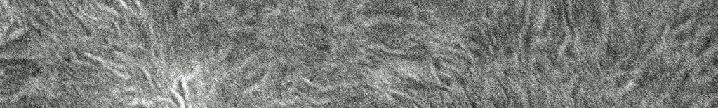


187 a MD TD b MD TD Figure 5.7 Morphology of LDPE single-layer films (a) Low stress (TUR=3.5) and (b) High stress (TUR=10) 168
188 Figure 5.8 presents the morphology of the LDPE layer of coextruded films processed under identical conditions. The effect of coextrusion on the orientation can be noted from the morphology of the films in MD-TD plane. As seen in Figures 5.8a and b, for the coextruded films, there is a lack of preferred alignment of lamellae in the plane. Figure 5.8a shows the random lamellar arrangement for the film subjected to low stress. However, at high stress, we observe only a partial alignment of lamella with the b-axis of the lamellae tending to align perpendicular to MD, as shown in Figure 5.8b. 169


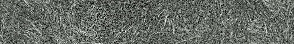


189 a MD TD b MD TD Figure 5.8 Morphology of LDPE coextruded film (a) Low stress (TUR=3.5) and (b) High stress (TUR=10) 170
190 The kinematics of bicomponent blown film process are fairly complex[6]. After the first layer freezes, the stresses are borne by the solidified layer (PP in the present case), while LDPE is still in the molten state. The molecular chains in molten LDPE tend to relax, and the extent depends on the crystallization time-difference between the two components. The longest or terminal relaxation time of LDPE measured by stressrelaxation experiments are 9s, 23s and 43s for temperatures of 150 C, 125 C and 90 C, respectively. The relaxation time of LDPE was also verified by dynamic frequency sweep experiments (Cole-Cole plot)[9] were 0.55 s, 5 s and 11 s for temperatures 200 C, 150 C and 125 C respectively. Thus, the difference in microstructure can be a consequence of the low stress on molten LDPE layer after the freeze-line height (FLH), where the PP layer starts to crystallize (122 C). Such low stress in LDPE layer could possibly cause the high molecular weight chains, which serve as fibrillar nuclei for row-nucleated structure, to relax during the process before the onset of LDPE crystallization. It is known that the maximum stress occurs near the frost-line and the extent of stress-induced crystallization is determined by the number of long chains that get extended during the onset of crystallization. The difference in the morphology of LDPE observed for the single (Figure 5.7b) and coextruded (Figure 5.8b) films can be attributed to the crystallization-time difference between the onset of crystallization of PP and LDPE and the relaxation of LDPE. The crystallization-time difference at high stress was ~ 3.2 s. Although smaller than the relaxation times (23-43s) in the temperature range of interest (125 C-99 C), partial 171
191 relaxation of chains can still occur for long-chain fibrils, which will reduce the extent of row-nucleation. These results are consistent with observations reported in the literature[6] that an individual polymer can behave differently in a multi-component film versus that as a single-layer film. The differences in the morphology and orientation of the LDPE indicate that the simple rule of additivity cannot be used to predict properties in PP/LDPE blown film. The effect of coextrusion on the microstructure of polypropylene (PP) and lowdensity polyethylene (LDPE) bilayer films (PP/LDPE) was investigated by the use of Raman spectroscopy. The onset crystallization-time difference for PP vs LDPE components is an important parameter that controls the orientation and morphology of the coextruded films. Although, the overall molecular orientation of PP and LDPE multiple layers was not affected, single-layer LDPE films displayed some row-nucleation of crystals, but not the LDPE layer in coextruded films. Also, there was a slight decrease of crystalline a-axis orientation for coextruded LDPE layer relative to that for single-layer LDPE films Conclusions It was found that the crystallization-time difference for the onset of crystallization of PP and LDPE plays an important role in determining the orientation and morphology of the components during PP/LDPE bilayer blown film extrusion. Raman spectroscopy enabled measurement of this crystallization-time difference during PP/LDPE bilayer film 172
192 extrusion. WAXD and SEM results indicated that the LDPE layer is affected during PP/LDPE coextrusion and does not form significant row-structures even at high stresses relative to that observed for single-layer LDPE films. These changes can be attributed to the existence of crystallization-time difference between the components during coextrusion. Therefore, the rheological behavior and crystallization of the various components can have a profound effect on the microstructure and properties of the multilayer films relative to that observed for single layer films. 173
193 5.4. References 1. Kimberly A, Jeffrey S, Patrick B, and Frank S. Science 2000; Olley RH and Bassett DC. Polymer 1982;23(12): Dees JR and Spruiell JE. Journal of Applied Polymer Science 1974;18(4): Nadella HP, Henson HM, Spruiell JE, and White JL. Journal of Applied Polymer Science 1977;21(11): Stein RS. Journal of Polymer Science 1957; Morris BA. Journal of Plastic Film & Sheeting 1999;15(1): Gururajan G and Ogale AA. Plastics Rubber and Composites 2005;34(5-6): Keller A and Kolnaar JWH. Orientational Phenomena in Polymers: Springer Berlin / Heidelberg, Zhang XM, Elkoun S, Ajji A, and Huneault MA. Polymer 2004;45(1):
194 CHAPTER SIX CONCLUSIONS AND RECOMMENDATIONS This chapter summarizes major conclusions drawn from this dissertation. First, conclusions are drawn based on research results presented in Chapters 2, 3, 4 and 5, and then recommendations are provided for future studies Conclusions In Chapter 2, the use of real-time polarized Raman spectroscopy to measure molecular orientation development during blown film extrusion of a low-density polyethylene (LDPE) and polypropylene (PP) was established. Polarized and nonpolarized Raman spectra along with temperature profiles were obtained at different locations along the blown film line, starting from the molten state near the die and extending up to the solidified state near nip-rolls. The experimental difficulties involved in the measurements were overcome by assuming invariant Raman tensor components during phase transformation and conducting measurements on the bubble subjected to uniaxial extension. The second and fourth coefficients of the orientation distribution function (P 2 and P 4, respectively) were quantitatively determined from the polarized scattering intensities of the band at 1130 cm -1. The orientation parameters, P 2 and P 4 increased with the crystalline development. The difference in P 2 values measured from 175
195 Raman measurements and WAXD techniques was noted. The increase in orientation of the chains even after even after the bubble shape is locked into place indicated that reorganization of the chain orientation continues far above the frost line height. The potential of real-time Raman spectroscopy as a rapid microstructure monitoring tool for better process control during blown film extrusion was established. Although Raman spectroscopy is a convenient technique, it is not a primary measurement technique to obtain crystallinity and orientation. Therefore, for the first time, real-time wide-angle X-ray diffraction (WAXD) was attempted during blown film extrusion. In Chapter 3, the feasibility of using wide-angle X-ray diffraction for real-time crystallinity measurements during the blown film extrusion of low-density polyethylene was established. From the evolution of (110) and (200) peaks, it was evident that the crystallization process starts near the frost-line height (FLH), shows a steep growth immediately past the FLH, and then plateaus at higher axial distances near the nip-rolls. From simultaneous Raman spectroscopy and WAXD measurements, it was concluded that the real-time crystallinity profiles obtained from the two independent techniques were consistent. Multi-layer blown films are of significant industrial importance to make packaging films of superior properties. Therefore, real-time Raman measurements were extended from single-layer blown film extrusion to multi-layer blown film extrusion. In Chapter 4, real-time Raman spectroscopic measurement of crystallinity of the individual components, LDPE and i-pp, of a bilayer film (LDPE/PP) during blown-film extrusion was reported. The possibilities and limitations of real-time Raman spectroscopy during 176
196 LDPE/PP coextrusion are discussed. Raman spectroscopy was shown to be a promising technique for real-time monitoring of crystalline growth of individual components in bicomponent LDPE/PP blown films. The technique using unpolarized probes was found to be valid for PE/PP bilayer films in which the components show good optical clarity and have layer thicknesses of approximately μm. The offline conventional and confocal Raman measurements indicated that the cm -1 crystalline bands of PP are unaffected by the presence of PE and the use of cm -1 does not significantly affect the calculation of crystallinity of PE in PP/PE films. The crystallinity profile was consistent with the observation of a double plateau in PE/PP blown films. The crystalline growth of PP and PE components increased as the take-up speed was increased. Finally, in Chapter 5, the crystallinity development in individual components measured using Raman spectroscopy was utilized to understand the complex multilayer blown film extrusion process. The effect of the blown film coextrusion process on the molecular orientation and crystalline morphology of the components in LDPE/PP bilayer blown films was investigated. It was found that the crystallization-time difference for the onset of crystallization of PP and LDPE plays an important role in determining the orientation and morphology of the components during PP/LDPE bilayer blown film extrusion. Raman spectroscopy enabled measurement of this crystallization-time difference during PP/LDPE bilayer film extrusion. WAXD and SEM results indicated that the LDPE layer is affected during PP/LDPE coextrusion and does not form significant row-structures even at high stresses relative to that observed for single-layer LDPE films. These changes can be attributed to the existence of crystallization-time 177
197 difference between the components during coextrusion. It was concluded that the rheological behavior and crystallization of the various components can have a profound effect on the microstructure and properties of the multilayer films relative to that observed for single layer films. Thus, the dissertation investigated real-time Raman spectroscopy and real-time wide-angle X-ray diffraction techniques for crystallinity and orientation measurements during blown film extrusion of polyolefins Recommendations for Future Work In Chapter 2, the orientation measurements were obtained using polarized Raman spectroscopy. The Raman tensor ratios were assumed to be invariant, i.e., they do not change with crystallinity and orientation. Therefore, the tensor elements obtained on the processed film were used to obtain orientation parameters at other axial distances in this study. Although this simplified approach captured the important structural transformation occurring during the film blowing, a complete set of 12 spectra can be recorded in different polarization geometries to accurately estimate the tensor ratios at each position in the film line. The experimental difficulties for conducting right-angle scattering measurements, which occur due to motion of the bubble, can be addressed using (i) a state-of-the-art motion control system, and (ii) Raman probes attached with video camera arrangements that can be custom-built for the application. 178
198 In Chapter 3, real-time wide-angle X-ray diffraction measurements were successfully utilized to measure crystallinity during polyethylene blown film extrusion. This primary measurement technique validated crystallinity data from Raman spectroscopy. The diameter of the bubble during real-time X-ray diffraction measurements was limited to the gap in the platform that holds the X-ray gun and the image-plate. Consequently, only small diameter bubble could be investigated real-time. It was reported that the offline measurements can be conducted on bigger bubble diameters. However, to conduct such measurements on a high BUR bubble, the experimental setup needs to be changed. The orientation and crystallinity measurements can then be extended for biaxial orientation. In Chapter 4, the real-time crystallinity evolution of the individual components, PP and LDPE, was reported. The unique characteristic crystalline peaks of PP and LDPE enabled such measurements without influence of one layer over the other. The significance of such measurements was reported in Chapter 5. The measurements can be extended to coextrusion of other polyolefins such as HDPE and LLDPE to understand the effect of coextruding different polymers. The technique can also be extended for three component blown films. The utilization of real-time Raman spectroscopy for polymers other than polyolefins would be great commercial because most multilayer blown film coextrusion involves using a tie-layer resin. It will be interesting to explore the effect of tie-layer resin on the microstructural changes during the multilayer film process. One of the important objectives of conducting real-time measurements was to help in the development of process models. The experimental verification of single-layer 179
199 blown film extrusion process model has been carried out at the Center for Advanced Engineering Fibers and Films (CAEFF). In the future, the real-time data on multilayer blown film extrusion can be used to develop and validate a process-model for the complex multilayer blown film extrusion. 180
200 APPENDICES 181
201 Appendix A Multilayer Blown Film Extrusion The following information is the procedure for extrusion of single and bilayer films using the equipment in the Laboratory located in Rhodes, Room 302. I. Initial Setup a. Begin by turning on the power supply of the extruder. i. This can be done by turning on the circuit breakers. b. Turn on the water hoses to cool the extruder hoppers. c. From there, turn on the heaters in each of the extruder zones, pumps and die. i. There will be different temperature ( o C) requirements at various zones, depending on the material processed; these are approximate temperatures. See Table A.1 for details. ii. If extruding a mixture, set the process condition to those of the polymer with the highest required values. Table A.1: Temperature at various zones of the extruder. Material Zone 1 Zone 2 Zone 3 Zone 4 Zone 5 Zone 6 Pump Die i-pp LDPE d. Turn on the air blower, and keep the air influx at the ring e. Allow the heaters at the various zones to come to temperature. II. Procedure 1. The polymer pellets are filled into the extruder hoppers. 2. Turn on the pumps and set the flow rate to a value of 3. NOTE: Anything above this may damage the pumps; Ensure that the amperage meter for the pumps is below 3 amps at all times. 3. Gradually bring up the pump speed to a higher flow rate. a. Each polymer will require a different flow rate due to their viscous nature. See Table A.2 for details. Table A.2 : Material with Corresponding Metering Pump Reading Material Pump Values Isotactic Polypropylene 44.4 Low Density Polyethylene
202 4. Set the automated controller to ensure that the extruder provides sufficient material to the pump to maintain a constant flow rate. a. If there is a substantial decrease in pump pressure, this may be caused by the polymer melting in the hopper. b. To overcome this problem, use a long brass blunt ended object to force the melted polymer into the extruder. c. If this continues to occur, turn down the temperature in the zones closest to the hopper, and increase the water flow rate. 5. As the pumps push the melted polymer through the die, clean off the die 6. Turn on the compressed air valve, and allow a stream of air to enter using the knob located below the die. a. It will be important to control and measure the amount of air entering, since this leads to bubble formation leading to the blow-up ratio (BUR), so record this values. 7. Take the polymer exiting the extruding die and pull up which should force it into the shape of a film. 8. Continue to pull on the film until it is of sufficient length to place in the nip roller. a. Before placing the film into the nip rollers, thread the film between two stationary bars that will maintain the film in place. 9. Turn on the nip roller. a. Set to a rotational speed of about 30 rpm. This will be used to calculate the take-up ratio (TUR). 10. Allow the film to be pulled up using the rollers. a. If notable creases are contained within the films, clean the inside of the die using a sharp thin brass tool. b. Be careful that the film does not stick to the rollers; if this occurs, stop the roller and cut the film. Remove the film caught in the roller, and repeat the process beginning with Step 7, but this time, pull in film as it leave the rollers to avoid the and sticking. 11. Collect the film at the tail end of the rollers. 12. Place in plastic container bags, and store for testing. 183
203 Appendix B Real-Time Raman Spectroscopy I. Initial Set-up 1. Raman system: 1. The real-time Raman system is custom-built Renishaw Raman system 100 with 200 mw near-infrared diode laser source. 2. The spectrometer can be coupled to non-polarized Inphotonics Ramanprobe (Norwood, MA), polarized Renishaw Raman probes (XY and XX) II. Operation and Data-processing 1. Switch ON, the spectrometer, laser source and the computer. 2. Connect the Raman probes to the Raman spectrometer. 3. Wait for at least 10 mins till the full-power of laser source is reached. 4. Check the laser power and wavelength using a laser power-meter 5. Click on the Renishaw Wire icon. 6. Do the x-calibration test by going to system check from collect menu. 7. Set appropriate tracks for the probes. Check 1 for external probe and check 3 for Renishaw probe. 8. Collect a spectrum of cyclohexane for calibration. Check for the peak at 800 cm -1. If it doesn t center at 800 cm -1, then go to experimental setup in collect menu and do offset correction for the difference (±). Collect the spectrum again and check the peak. 9. Set the experimental condition and stabilize the bubble at appropriate BUR and TUR. 10. Place the Raman probe on the XY micrometer stage that was on Z- platform. Turn OFF the light in the room. Focus the laser beam on the bubble. If the laser is focused is well, a bright sparkle on the sample can be noticed. 11. Set the accumulation time and click collect in the experimental set-up menu. 12. Click on save icon to store the spectrum in desired location in computer. 13. Collect at least three spectrum at each axial location. 14. Open the spectrum for analysis 15. First go to arithmetic and then smooth the spectrum using binomial function. 16. Second, fix the baseline for the spectrum. In the arithmetic menu, go to the baseline and check multipoint. 184
204 17. Save the processed spectrum with a new name. 18. Open the file and zoom on the peak and do curve fitting by clicking on arithmetic menu. 19. Right-click on the mouse to see the mix Gaussian-Lorentzian function. 20. After iteration is finished, note the center, area, height and % Lorentzian in the fit. III. Shut down 1. Exit the Renishaw WiRE program. 2. Switch the computer Off. 3. Turn off the spectrometer and the laser source. IV. Precautions during operation 1. Do not bend or step-up on the optic-fiber cables of the Raman probes. 2. Do not look at the laser with direct eye. 185
205 Appendix C Scanning Electron Microscopy I. Initial set-up: 1. Apparatus: The Hitachi S-4800 Field Emission Scanning Electron Microscope (CFE-SEM) is located at Electron Microscopy facility at Advanced Materials Research Laboratory, Clemson, SC 2. Collect the following items before experiment: II. Permanganic Etching A. Hot-plate and a stirrer. B. Glass beakers -500 ml C. Permanent marker D. Potassium permanganate (KMnO 4 ), Acetone, Orthophosphoric acid (H 3 PO 4,100 ml), Sulphuric acid (H 2 SO 4, 100 ml), Hydrogen peroxide (H 2 O 2, 100 ml), distilled water (300 ml), Acetone (200 ml) E. Liquid nitrogen in flask. F. Dry-ice. 1. Blown film samples are marked with machine and transverse directions and cryogenically fractured. 2. First, dissolve 0.7 wt % KMnO 4 in 2:1 (vol. ratio) of H 2 SO 4 and H 3 PO 4 and stir the solution at room temperature for approximately 1 hr. (Extreme Caution: Do not pour H 2 SO 4 and H 3 PO 4 mixture over KMnO 4 ) 3. The cut film samples are treated with the solution for mins. 4. The samples are taken out of the beaker. 5. The samples are washed with a mixture of 2 volume of H 2 SO 4 and 7 volumes of water kept in a dry-ice bath for 10 minutes. 6. The solution is decanted and washed with H 2 O 2, then using distilled water and finally with acetone. They are dried for 12 hrs. 7. The etched film samples are ready for microscopy. III. Scanning electron microscopy 1. First, the films are mounted on the sample-holder in the appropriate direction for SEM and coated with platinum using Hummer 6.2 Sputtering system in the Electron Microscopy lab. Follow the step-by-step instructions provided beside the machine. 2. The sample-holder is tightened to the arm and the chamber is closed. Wait for the chamber to reach vacuum (the light flash stops). 186
206 3. The arm can now be taken inside the instrument chamber by opening the chamber door. Then it is placed on the instrument mount. 4. The sample movement can be controlled using the joy-stick provided in the system. 5. Start with low magnification to locate the appropriate directions and collect images at the desired magnification. IV. Precautions 1. Do not pour H 2 SO 4 and H 3 PO 4 mixture over KMnO Wait for the chamber to reach the required vacuum. Do not move the arm inside instrument before vacuum is reached. 3. Do not sputter coat the films for more than 90 secs minutes. The coating could mask the morphological features of the sample. 187
207 Appendix D Birefringence (Berek-Compensator Method) 1. Theory Deformation during the film blowing process produces biaxial orientation. For biaxial films, the three principal refractive indices (α, β, γ) are different in each direction (1,2 and 3) because of the anisotropy caused by the orientation of the polymer chains in the film. Birefringence is a measure of optical retardation of light passing through different planes of the film. This is dependent on the difference in the refractive indices in the plane of the film and its thickness. In order to arrive at complete picture of molecular orientation in the film, In-plane (Δn 12 ) and out-of-plane (Δn 13, Δn 23 ) birefringence values are measured using an optical microscope BX-60F5 (Olympus Optical Co. Ltd., Japan) fitted with cross-polarizers and U-TCB Berek compensator (Olympus Optical Co. Ltd., Japan) using the method described by Stein 1. 1 φ Film α MD Light Beam to Analyzer Out -of -plane 3 Δ Light Beam θ γ n 13 from d polarizer Thickness 2 In -plane β Δ n 12 Figure D.1. Incident light beam with respect to principal axes and optic axes of film [1] Figure D.1 presents the birefringence through the film. The out-of-plane birefringences: Δn 13, Δn 23 are indication of molecular orientation in machine and transverse direction respectively while the in-plane birefringence (Δn 12 ) is indication of film anisotropy. Inplane (Δn 12 =β-α) birefringence can be obtained directly by measuring retardation through the film. 188


208 For the case of out-of-plane birefringences, R.S.Stein derived the following equation that relates birefringence with the retardation of the film with out-of-plane birefringence: Δn 13 =γ-α = R λ0 d 0 Also, Δn 23 =Δn 13 -Δn 12 0 sin Rφ (1 n 2 sin φ / n where λ0 is the wavelength of the light used in vacuum, d 0 is the thickness of the film, n is the average index of refraction for the film obtained from a refractometer or literature. R 0 is the retardation of the film for normal incidence, expressed in units of number of waves, and R φ is the retardation of the film tilted through the angle Φ. The retardation is measured using a UTB compensator. The film should be placed on a tilting stage to rotate the sample to incline with respect to the incident beam φ ) 1/ 2 2. Procedure 2.1. The arrangement of the compensator is as shown in Figure D.2a. The crystal inside the compensator is mounted on a frame in the way shown in Figure D.2b. At 0 of the compensator, the optic axis of the crystal is aligned with the light coming from the polarizer. a b Figure D.2 a. Berek Compensator b. Crystal inside compensator (Reproduced with permission from Prof. Michael W. Davidson, The Florida State University) 189
RAMAN STRUCTURAL STUDY OF OLEFIN BLENDS
 RAMAN STRUCTURAL STUDY OF OLEFIN BLENDS Authors: Yu.V. Zavgorodnev, E.A. Sagitova, G.Yu. Nikolaeva, K.A. Prokhorov, P.P. Pashinin, L.A. Novokshonova, T.M. Ushakova, E.E. Starchak, E.M. Antipov DOI: 10.12684/alt.1.79
Calcium Carbonate in Blown HDPE Film
 Calcium Carbonate in Blown HDPE Film New Developments to Increase Productivity and Profitability by Gil Morieras - Marketing Manager Polyolefines (Omya) and Dr. Gerard Schaeffer (GS Technology) Many interesting
A study of plastic plateau disappearance in stress-strain curve of annealed polypropylene films during stretching
 The 2012 World Congress on Advances in Civil, Environmental, and Materials Research (ACEM 12) Seoul, Korea, August 26-30, 2012 A study of plastic plateau disappearance in stress-strain curve of annealed
Effect of Processing Parameters on Polypropylene Film Properties
 Vol.2, Issue.5, Sep.-Oct. 2012 pp-3056-3060 ISSN: 2249-6645 Effect of Processing Parameters on Polypropylene Film Properties Ikilem Gocek 1, Sabit Adanur 2 1 (Department of Textile Engineering, Istanbul
CHAPTER V. Microporous Membranes of Polyoxymethylene from a Melt-Extrusion Process: (I) Effects of Resin Variables and Extrusion Conditions
 Effects of Resin Variables and Extrusion Conditions") 172 CHAPTER V Microporous Membranes of Polyoxymethylene from a Melt-Extrusion Process: (I) Effects of Resin Variables and Extrusion Conditions ABSTRACT A two part study utilizing polyoxymethylene (POM)
172 CHAPTER V Microporous Membranes of Polyoxymethylene from a Melt-Extrusion Process: (I) Effects of Resin Variables and Extrusion Conditions ABSTRACT A two part study utilizing polyoxymethylene (POM)
Effect of Material Properties and Processing Conditions on PP Film Casting
 Effect of Material Properties and Processing Conditions on PP Film Casting Kenneth Aniunoh and Graham Harrison Department of Chemical and Biomolecular Engineering and Center for Advanced Engineering Fibers
Influence of extrusion coating processing conditions on structure and tensile properties of some polyethylene grades
 ANNUAL TRANSACTIONS OF THE NORDIC RHEOLOGY SOCIETY, VOL. 1, 22 Influence of extrusion coating processing conditions on structure and tensile properties of some polyethylene grades Nils Toft and Mikael
9/28/2013 9:26 PM. Chapter 3. The structure of crystalline solids. Dr. Mohammad Abuhaiba, PE
 Chapter 3 The structure of crystalline solids 1 2 Why study the structure of crystalline solids? Properties of some materials are directly related to their crystal structure. Significant property differences
An Experimental and Numerical Study of the Film Casting Process
 Clemson University TigerPrints All Dissertations Dissertations 12-2007 An Experimental and Numerical Study of the Film Casting Process Kenneth Aniunoh Clemson University, kaniuno@clemson.edu Follow this
COMPARISON OF CAST FILM AND BLOWN FILM 9 - LAYER BARRIER FILM
 COMPARISON OF CAST FILM AND BLOWN FILM 9 - LAYER BARRIER FILM Gerhard Winkler Windmöller & Hölscher / Germany ABSTRACT Above-average growth rates in the field of cast film production and stretch film,
Ionic Aggregates in Zn- and Na-neutralized Poly(ethylene-ran-methacrylic acid)
") University of Pennsylvania ScholarlyCommons Departmental Papers (MSE) Department of Materials Science & Engineering December 2005 Ionic Aggregates in Zn- and Na-neutralized Poly(ethylene-ran-methacrylic
University of Pennsylvania ScholarlyCommons Departmental Papers (MSE) Department of Materials Science & Engineering December 2005 Ionic Aggregates in Zn- and Na-neutralized Poly(ethylene-ran-methacrylic
Experiment 2b X-Ray Diffraction* Optical Diffraction Experiments
 * Experiment 2b X-Ray Diffraction* Adapted from Teaching General Chemistry: A Materials Science Companion by A. B. Ellis et al.: ACS, Washington, DC (1993). Introduction Inorganic chemists, physicists,
Measurement of Residual Stress by X-ray Diffraction
 Measurement of Residual Stress by X-ray Diffraction C-563 Overview Definitions Origin Methods of determination of residual stresses Method of X-ray diffraction (details) References End Stress and Strain
9/16/ :30 PM. Chapter 3. The structure of crystalline solids. Mohammad Suliman Abuhaiba, Ph.D., PE
 Chapter 3 The structure of crystalline solids 1 Mohammad Suliman Abuhaiba, Ph.D., PE 2 Home Work Assignments HW 1 2, 7, 12, 17, 22, 29, 34, 39, 44, 48, 53, 58, 63 Due Sunday 17/9/2015 3 Why study the structure
Tie layer technology for multilayer coextrusion of single-use biopharma bags
 Engineering Conferences International ECI Digital Archives Single-use Technologies II: Bridging Polymer Science to Biotechnology Applications Proceedings 5-8-2017 Tie layer technology for multilayer coextrusion
EXTRUSION OF ELASTOMER FILM, EFFECTS OF ELASTOMER DESIGN ON CHILL ROLL STICKING
 EXTRUSION OF ELASTOMER FILM, EFFECTS OF ELASTOMER DESIGN ON CHILL ROLL STICKING Mary Ann Jones, Todd Hogan, and Sarah Gassner, The Dow Chemical Company, Midland, MI Abstract Sticking of plastic webs to
Laser Welding of Engineering Plastics
 Laser Welding of Engineering Plastics Technical Information Further information on individual products: www.ultramid.de www.ultradur-lux.basf.com www.ultrason.de www.plasticsportal.eu/ultraform 2 LASER
Carbon nanostructures. (http://www.mf.mpg.de/de/abteilungen/schuetz/index.php?lang=en&content=researchtopics&type=specific&name=h2storage)
") Carbon nanostructures (http://www.mf.mpg.de/de/abteilungen/schuetz/index.php?lang=en&content=researchtopics&type=specific&name=h2storage) 1 Crystal Structures Crystalline Material: atoms arrange into a
Carbon nanostructures (http://www.mf.mpg.de/de/abteilungen/schuetz/index.php?lang=en&content=researchtopics&type=specific&name=h2storage) 1 Crystal Structures Crystalline Material: atoms arrange into a
Local buckling of slender aluminium sections exposed to fire. Residual stresses in welded square hollow sections of alloy 5083-H111
 Netherlands Institute for Metals Research Eindhoven University of Technology TNO Built Environment and Geosciences Report no. 8 Local buckling of slender aluminium sections exposed to fire Residual stresses
Extrusion. Key Issues to Address. Lecture 2. Process. Process Variants. Process Analysis. Problem Solving
 Extrusion Lecture 2 Chapter 4 Key Issues to Address Process Process Variants Process Analysis Problem Solving S.V. Atre 1 Extrusion Material is forced to flow through a die orifice to provide long continuous
Chapter 14 Polymers CHAPTER 7 POLYMERIC MATERIALS. Ancient Polymer History. Rubber balls used by Incas Noah used pitch (a natural polymer) for the ark
 for the ark") Chapter 14 Polymers What is a polymer? Polymers are organic materials made of very large molecules containing hundreds of thousands of unit molecules called mers linked in a chain-like structure (repeated
Chapter 14 Polymers What is a polymer? Polymers are organic materials made of very large molecules containing hundreds of thousands of unit molecules called mers linked in a chain-like structure (repeated
METHOD TO EVALUATE BIAXIAL STRETCH RATIOS IN STRETCH BLOW MOLDING
 METHOD TO EVALUATE BIAXIAL STRETCH RATIOS IN STRETCH BLOW MOLDING Masoud Allahkarami 1, 2, Sudheer Bandla 2, and Jay C. Hanan 1 1 Mechanical and Aerospace Engineering, Oklahoma State University, Tulsa,
Chapter 5. Differential Scanning Calorimetry
 Chapter 5. Differential Scanning Calorimetry 5.1 Introduction The discussion in Chapter 2 clearly illustrates the fact that the crystallization process and the resulting morphology in polymers are largely
The Raman effect, discovered in 1928 by C.V. Raman in his
 Refined Raman Spectroscopy Bringing New Insight into INDUSTRIAL PROCESSES Sophie Morel and Fran Adar Fiber probes and ease of use make Raman spectroscopy systems attractive for monitoring process control
Polyethylene & Polypropylene in Flexible Barrier Packaging
 2009 Consumer Packaging Solutions for Barrier Performance Course Polyethylene & Polypropylene in Flexible Barrier Packaging Presented by: Kelly R. Frey Extrusion Coating Technical Service Chevron Phillips
Endex Foam Extrusion General Information Guide
 Endex International Innovation for the Future Endex Foam Extrusion General Information Guide Section 01 - Foam Extrusion Foam extrusion, in simple terms, consists of mixing a chemical foaming agent with
4. Model of Crystallites (Morphology)
") 4. Model of Crystallites (Morphology) 4. Model of Crystallites (Morphology) Packing: arrangement of chain in crystals 1) Fringed micelle model 2) Folded chain model: - single crystal - spherulite - unit
4. Model of Crystallites (Morphology) 4. Model of Crystallites (Morphology) Packing: arrangement of chain in crystals 1) Fringed micelle model 2) Folded chain model: - single crystal - spherulite - unit
Polypropylene or polypropene (PP) is a thermoplastic polymer, made from the monomer propylene (propene):
 is a thermoplastic polymer, made from the monomer propylene (propene):") Polypropylene (PP) Technical University of Gabrovo Milena Koleva General General Polypropylene or polypropene (PP) is a thermoplastic polymer, made from the monomer propylene (propene): Its molecular mass
Polypropylene (PP) Technical University of Gabrovo Milena Koleva General General Polypropylene or polypropene (PP) is a thermoplastic polymer, made from the monomer propylene (propene): Its molecular mass
Flow-Induced Crystallization of Isotactic Polypropylene and Random Polyethylene- Polypropylene Copolymers
 University of Nebraska - Lincoln DigitalCommons@University of Nebraska - Lincoln Mechanical (and Materials) Engineering -- Dissertations, Theses, and Student Research Mechanical & Materials Engineering,
BLOW MOULDING. Blow moulding is a process used to produce hollow objects from thermoplastic.
 1 BLOW MOULDING Blow moulding is a process used to produce hollow objects from thermoplastic. The basic blow moulding process has two fundamental phases. First, a parison (or a preform) of hot plastic
 www.reedychemicalfoam.com FOAMS 2016 Kinetic Nucleators maximize cell distribution in foam extrusion September 14-15, 2016 2 1. Why Use Chemical Foam? 2. CFA types 3. Modern CFA Expectations 4. Nucleation
PLMSE 406 Practice Test A polymer chain in the melt or in the rubbery state has an average end-to-end distance that is proportional to
 PLMSE 406 Practice Test 2 1. A polymer chain in the melt or in the rubbery state has an average end-to-end distance that is proportional to a. N b. N 0.75 c. N 0.6 d. N 0.5 e. N 0.33 where N is the number
Orientation / Texture Polyethylene films
 Application Note PT-002 Orientation / Texture Polyethylene films Polyethylene (PE) film is one of the most commonly used polymeric products and orientation measurements of this material are of great interest.
Chain Folding PRIMARY CILIUM SECONDARY CILIUM. (c) PRIMARY CILIA. Figure by MIT OCW.
 PRIMARY CILIA. Figure by MIT OCW.") Chain Folding PRIMARY CILIUM (a) (b) SECONDARY CILIUM (c) PRIMARY CILIA Figure by MI OCW. Chain Folding Perfect vs Irregular Perfect Folding (Regular Adjacent) Irregular Folding (Switchboard) (Keller,
Chain Folding PRIMARY CILIUM (a) (b) SECONDARY CILIUM (c) PRIMARY CILIA Figure by MI OCW. Chain Folding Perfect vs Irregular Perfect Folding (Regular Adjacent) Irregular Folding (Switchboard) (Keller,
Transmission Electron Microscopy (TEM) Prof.Dr.Figen KAYA
 Prof.Dr.Figen KAYA") Transmission Electron Microscopy (TEM) Prof.Dr.Figen KAYA Transmission Electron Microscope A transmission electron microscope, similar to a transmission light microscope, has the following components along
Transmission Electron Microscopy (TEM) Prof.Dr.Figen KAYA Transmission Electron Microscope A transmission electron microscope, similar to a transmission light microscope, has the following components along
Rheological Studies on Radiation Modified Polyethylene Resins. Song Cheng* and Ed Phillips
 Rheological Studies on Radiation Modified Polyethylene Resins Song Cheng* and Ed Phillips Sterigenics Advanced Applications, 7695 Formula Place, San Diego, CA 92121-2418 * Corresponding author. Email address:
11.3 The analysis of electron diffraction patterns
 11.3 The analysis of electron diffraction patterns 277 diameter) Ewald reflecting sphere, the extension of the reciprocal lattice nodes and the slight buckling of the thin foil specimens all of which serve
Physical structure of matter. Monochromatization of molybdenum X-rays X-ray Physics. What you need:
 X-ray Physics Physical structure of matter Monochromatization of molybdenum X-rays What you can learn about Bremsstrahlung Characteristic radiation Energy levels Absorption Absorption edges Interference
Blown Film Processes. Bubble in the Real World. Blown Film Properties. The Ultimate Quality Control Tool
 2009 Flexible Packaging Summit Consumer Packaging Solutions for Barrier Performance Course Blown Film Processes and Troubleshooting The Ultimate Quality Control Tool Presented by: Paul Waller President
Thin Film Characterizations Using XRD The Cases of VO2 and NbTiN
 Thin Film Characterizations Using XRD The Cases of VO2 and NbTiN A thesis submitted in partial fulfillment of the requirement for the degree of Bachelor of Arts / Science in Physics from The College of
ELONGATIONAL FLOW IN MULTIPLE SCREW EXTRUDERS
 ELONGATIONAL FLOW IN MULTIPLE SCREW EXTRUDERS J. E. Loukus and A. C. Halonen M. Gupta GS Engineering Plastic Flow, LLC Houghton, MI 4993 Houghton, MI 4993 Abstract Flows of a low-density polyethylene in
Module 8: Composite Testing Lecture 36: Quality Assessment and Physical Properties. Introduction. The Lecture Contains
 Introduction In the previous lecture we have introduced the needs, background and societies for mechanical testing of composites. In this lecture and subsequent lectures we will see principles for the
UNIT V -CRYSTAL STRUCTURE
 UNIT V -CRYSTAL STRUCTURE Solids are of two types: Amorphous and crystalline. In amorphous solids, there is no order in the arrangement of their constituent atoms (molecules). Hence no definite structure
Micophotometric Control of Particles and Inhomogeneities in Flowing Polymer Melts during Extrusion Processing
 M.Stephan, S.Große: Micophotometric Control of Particles and Inhomogeneities in Flowing Polymer Melts during Extrusion Processing Workshop January, 28 th -29 th 2005, Dresden Particulate Heterogeneities
Earth & Planetary Science Applications of X-Ray Diffraction: Advances Available for Research with our New Systems
 Earth & Planetary Science Applications of X-Ray Diffraction: Advances Available for Research with our New Systems James R. Connolly Dept. of Earth & Planetary Sciences University of New Mexico 401/501
A MODEL FOR RESIDUAL STRESS AND PART WARPAGE PREDICTION IN MATERIAL EXTRUSION WITH APPLICATION TO POLYPROPYLENE. Atlanta, GA 30332
 Solid Freeform Fabrication 2016: Proceedings of the 26th 27th Annual International Solid Freeform Fabrication Symposium An Additive Manufacturing Conference A MODEL FOR RESIDUAL STRESS AND PART WARPAGE
1 Polymer Processing. 1.1 Introduction
 1 Polymer Processing 1.1 Introduction Polymeric materials often called plastics in popular usage are ubiquitous in modern life. Applications range from film to textile fibers to complex electronic interconnects
EXPERIMENTAL INVESTIGATION ON COOLING RATE FOR CENTRIFUGAL CASTING Kirti Kanaujiya, Yugesh Mani Tiwari Department of Mechanical Engineering
 ISSN 2320-9135 1 International Journal of Advance Research, IJOAR.org Volume 3, Issue 9, September 2015, Online: ISSN 2320-9135 EXPERIMENTAL INVESTIGATION ON COOLING RATE FOR CENTRIFUGAL CASTING Kirti
G. M. Mcnally, C. M. Small, W. R. Murphy, G. Garrett. To cite this version: HAL Id: hal https://hal.archives-ouvertes.
 The Effect of Polymer Properties on the Mechanical Behavior and Morphological Characteristics of Cast Polyethylene Film for Stretch and Cling Film Applications G. M. Mcnally, C. M. Small, W. R. Murphy,
Characterization of Materials Using X-Ray Diffraction Powder Diffraction
 Praktikum III, Fall Term 09 Experiment P1/P2; 23.10.2009 Characterization of Materials Using X-Ray Diffraction Powder Diffraction Authors: Michael Schwarzenberger (michschw@student.ethz.ch) Philippe Knüsel
MICROWAVE MEASUREMENTS OF NYLON-12 POWDER AGEING FOR ADDITIVE MANUFACTURING. N. Clark 1, F. Lacan and A. Porch
 Solid Freeform Fabrication 207: Proceedings of the 28th Annual International Solid Freeform Fabrication Symposium An Additive Manufacturing Conference Reviewed Paper MICROWAVE MEASUREMENTS OF NYLON-2 POWDER
Cavitation during tensile deformation of isothermally crystallized polypropylene and high-density polyethylene
 Colloid Polym Sci (2013) 291:773 787 DOI 10.1007/s00396-012-2789-5 ORIGINAL CONTRIBUTION Cavitation during tensile deformation of isothermally crystallized polypropylene and high-density polyethylene Andrzej
S. Lanceros-Mendez 1. Universidade do Minho, Campus de Azurém, Guimarães, Portugal
 Extrusion of poly(vinylidene fluoride) filaments: Effect of the processing conditions and conductive inner core on the electroactive phase content and mechanical properties A. Ferreira 1, P. Costa 1, H.
New results on losses correlation with structure
 New results on losses correlation with structure E. Coillet, V. Martinez, C. Martinet, A. Mermet Institut Lumière Matière Lyon, France M. Granata, V. Dolique, C. Michel, B. Sassolas, G. Cagnoli, Laboratoire
2. Definition of Environmental Stress Cracking (ESC)
") 2. Definition of Environmental Stress Cracking (ESC) Environmental stress cracking (ESC) in plastics means the failure at about room temperature due to continuously acting external and/or internal stresses
2. Definition of Environmental Stress Cracking (ESC) Environmental stress cracking (ESC) in plastics means the failure at about room temperature due to continuously acting external and/or internal stresses
Ceramic and glass technology
 29 Glass Properties Glass is an inorganic, nonmetallic material which cools to a rigid solid without crystallization. Glassy, or noncrystalline, materials do not solidify in the same sense as do those
a. 50% fine pearlite, 12.5% bainite, 37.5% martensite. 590 C for 5 seconds, 350 C for 50 seconds, cool to room temperature.
 Final Exam Wednesday, March 21, noon to 3:00 pm (160 points total) 1. TTT Diagrams A U.S. steel producer has four quench baths, used to quench plates of eutectoid steel to 700 C, 590 C, 350 C, and 22 C
How to Analyze Polymers Using X-ray Diffraction
 How to Analyze Polymers Using X-ray Diffraction Polymers An Introduction This tutorial will cover the following topics How to recognize different types of polymers Crystalline, semi-crystalline and amorphous
Introduction of L-MODU TM as a modifier for BOPP films
 Introduction of L-MODU TM as a modifier for BOPP films Performance Materials Laboratories 1 / 16 What is L-MODU TM...? Rigid Soft melting point (ºC) 150 100 PP WAX PE WAX APAO IPP Low Crystallinity HDPE
Polymer Materials Science
 Budapest University of Technology and Economics Department of Polymer Engineering Polymer Materials Science BMEGEPT9107, 2+0+0, 3 Credits 2. Morphological Structure of Polymers Lecturer: Prof. Dr. László
THE EFFECT OF PHTHALOCYANINE PIGMENT ON THE MICROSTRUCTURAL AND MECHANICAL PERFORMANCE OF PROPYLENE- ETHYLENE BLOCK COPOLYMER
 THE EFFECT OF PHTHALOCYANINE PIGMENT ON THE MICROSTRUCTURAL AND MECHANICAL PERFORMANCE OF PROPYLENE- ETHYLENE BLOCK COPOLYMER Major, I.F.M and McNally, G.M. Polymer Processing Research Centre, Queen s
Application Note. Raman Spectroscopy Analysis of Crystalline Polymorphs for Pharmaceutical Development
 Raman Applications in the Pharmaceutical Industry Impurity Analysis (Identification of micro impurities - sizes less than 1 µm) Evaluation of Synthetized Compounds (Structural analysis in combination with
Application Note. Introduction. Analysis of crystal polymorphism by Raman Spectroscopy for Medicine Development
 Application Note Analysis of crystal polymorphism by Raman Spectroscopy for Medicine Introduction Crystal polymorphism is a phenomenon where Raman applications in the pharmaceutical Industry compounds
Analysis of strongly absorbing chromophores by UV-visible ATR spectroscopy
 Technical Note: AN 915 Rev. B Analysis of strongly absorbing chromophores by UV-visible ATR spectroscopy Walter M. Doyle and Lani Tran This paper illustrates the potential of the attenuated total reflectance
Fundamentals of Crystalline State and Crystal Lattice p. 1 Crystalline State p. 2 Crystal Lattice and Unit Cell p. 4 Shape of the Unit Cell p.
 Fundamentals of Crystalline State and Crystal Lattice p. 1 Crystalline State p. 2 Crystal Lattice and Unit Cell p. 4 Shape of the Unit Cell p. 7 Crystallographic Planes, Directions, and Indices p. 8 Crystallographic
Three-dimensionally Packed Nano-helical Phase. in Chiral Block Copolymers
 Three-dimensionally Packed Nano-helical Phase in Chiral Block Copolymers Rong-Ming Ho, Yeo-Wan Chiang, Chi-Chun Tsai, Chu-Chieh Lin, Bao-Tsan Ko, Bor-Han Huang Supporting Information Table S1 Table S2
Polymers. Historical Classification
 Polymers The term polymer implies many "mers" or the building blocks...similar to the unit cell in metals. A polymer is a chemical compound or mixture of compounds formed by a process called polymerization,
THERMAL AGEING PERFORMANCE OF POLYOLEFINS UNDER DIFFERENT TEMPERATURES
 THERMAL AGEING PERFORMANCE OF POLYOLEFINS UNDER DIFFERENT TEMPERATURES Huang Wu, Yuming Lai, Ye (Jessica) Huang, Sharon Wu, Stacy Pesek, and Stefan Ultsch The Dow Chemical Company, Midland, MI Abstract
Fs- Using Ultrafast Lasers to Add New Functionality to Glass
 An IMI Video Reproduction of Invited Lectures from the 17th University Glass Conference Fs- Using Ultrafast Lasers to Add New Functionality to Glass Denise M. Krol University of California, Davis 17th
Olefin Block Copolymers in Health and Hygiene
 Olefin Block Copolymers in Health and Hygiene Ron Weeks The Dow Chemical Company Trademark of The Dow Chemical Company Trademark of The Dow Chemical Company 1 Breakthrough Performance & Cost Olefin block
3. Anisotropic blurring by dislocations
 Dynamical Simulation of EBSD Patterns of Imperfect Crystals 1 G. Nolze 1, A. Winkelmann 2 1 Federal Institute for Materials Research and Testing (BAM), Berlin, Germany 2 Max-Planck- Institute of Microstructure
Diffraction Basics. The qualitative basics:
 The qualitative basics: Diffraction Basics Coherent scattering around atomic scattering centers occurs when x-rays interact with material In materials with a crystalline structure, x-rays scattered in
Silver Diffusion Bonding and Layer Transfer of Lithium Niobate to Silicon
 Chapter 5 Silver Diffusion Bonding and Layer Transfer of Lithium Niobate to Silicon 5.1 Introduction In this chapter, we discuss a method of metallic bonding between two deposited silver layers. A diffusion
Experiment 7: Characterization of uncrosslinked natural rubber from rubber tree latex and of crosslinked natural rubber.
 Experiment 7: Characterization of uncrosslinked natural rubber from rubber tree latex and of crosslinked natural rubber. Aim: To study the stress-strain properties (and effects of time and temperature)
7-2E. Photonic crystals
 7-2E. Photonic crystals Purdue Univ, Prof. Shalaev, http://cobweb.ecn.purdue.edu/~shalaev/ Univ Central Florida, CREOL, Prof Kik, http://sharepoint.optics.ucf.edu/kik/ose6938i/handouts/forms/allitems.aspx
New Cu-based Bulk Metallic Glasses with High Strength of 2000 MPa
 Materials Science Forum Online: 2004-03-15 ISSN: 1662-9752, Vols. 449-452, pp 945-948 doi:10.4028/www.scientific.net/msf.449-452.945 2004 Trans Tech Publications, Switzerland New Cu-based Bulk Metallic
Introduction to Dynamic Mechanical Testing for Rubbers and Elastomers. Mackenzie Geiger Applications Scientist September 6, 2017
 Introduction to Dynamic Mechanical Testing for Rubbers and Elastomers Mackenzie Geiger Applications Scientist September 6, 2017 Is DMA Thermal Analysis or Rheology? Definitions Thermal Analysis measurement
A vapor (or gas) needs a completely enclosed container to have a definite volume; it will readily take on any shape imposed.
 needs a completely enclosed container to have a definite volume; it will readily take on any shape imposed.") Overview: Amorphous and crystalline solid states. States of matter. General description. A vapor (or gas) needs a completely enclosed container to have a definite volume; it will readily take on any shape
Overview: Amorphous and crystalline solid states. States of matter. General description. A vapor (or gas) needs a completely enclosed container to have a definite volume; it will readily take on any shape
CRYSTALLIZATION KINETICS OF SYNDIOTACTIC POLYPROPYLENE STUDIED BY TIME-DEPENDENT LIGHT ATTENUATION *
 Chinese Journal of Polymer Science Vol. 6, No., (008), 153 160 Chinese Journal of Polymer Science 008 World Scientific CRYSTALLIZATION KINETICS OF SYNDIOTACTIC POLYPROPYLENE STUDIED BY TIME-DEPENDENT LIGHT
Polymer MS/PhD Qualifying Exam
 Polymer MS/PhD Qualifying Exam FALL 2012 Time = 3 h Closed Books/Notes Use ONE blue book for each part. PART-1: General Polymer Chemistry 1. Write the structural repeat units for the following polymers:
THE MEASUREMENT OF SUBSURFACE RESIDUAL STRESS AND COLD WORK DISTRIBUTIONS IN NICKEL BASE ALLOYS
 THE MEASUREMENT OF SUBSURFACE RESIDUAL STRESS AND COLD WORK DISTRIBUTIONS IN NICKEL BASE ALLOYS Paul S. Prevéy Lambda Research, Inc. ABSTRACT A method of determining the diffraction peak width accurately
Orientation of a Chiral Srnectic C Elastomer by Mechanical Fields
 Polymers for Advanced Technologies Volume 5, pp. 231-235 Orientation of a Chiral Srnectic C Elastomer by Mechanical Fields Klaus Semmler and Heino Finkelmann Institut fur Makromolekulare Chemie und Freiburger
Correlating the scattered intensities of P3HT and PCBM to the current. densities of polymer solar cells
 Supplementary Information for Correlating the scattered intensities of P3HT and PCBM to the current densities of polymer solar cells Enrique D. Gomez*, Katherine P. Barteau, He Wang, Michael F. Toney,
Polymer Crystallization
 G. Reiter J.-U. Sommer (Eds.) Polymer Crystallization Observations, Concepts and Interpretations Springer Table of Contents 1 Introduction Jens-Uwe Sommer and Günter Reiter 1 2 Polymer Crystallization
Mechanical behavior of crystalline materials- Comprehensive Behaviour
 Mechanical behavior of crystalline materials- Comprehensive Behaviour In the previous lecture we have considered the behavior of engineering materials under uniaxial tensile loading. In this lecture we
New Evaluation Methods for Pressure Sensitive Adhesive (PSA) Tapes Used in the Semiconductor Industry
 Tapes Used in the Semiconductor Industry") New Evaluation Methods for Pressure Sensitive Adhesive (PSA) Tapes Used in the Semiconductor Industry by Tomoyuki Aogaki *, Hidefumi Miyagi * and Yoshihisa Kano * We propose new evaluation methods for
New Evaluation Methods for Pressure Sensitive Adhesive (PSA) Tapes Used in the Semiconductor Industry by Tomoyuki Aogaki *, Hidefumi Miyagi * and Yoshihisa Kano * We propose new evaluation methods for
Quiz on Monday covering: -symmetry operations -notations of axes, vectors, and face notation -Miller indices
 OTHER ANNOUNCEMENTS Quiz on Monday covering: -symmetry operations -notations of axes, vectors, and face notation -Miller indices 2 nd Draft of References due Monday Field Trip Saturday 10/4 and Sunday
Fundamentals of Crystalline State p. 1 Introduction p. 1 Crystalline state p. 2 Crystal lattice and crystal structure p. 4 Shape of the unit cell p.
 Preface p. xvii Fundamentals of Crystalline State p. 1 Introduction p. 1 Crystalline state p. 2 Crystal lattice and crystal structure p. 4 Shape of the unit cell p. 6 Content of the unit cell p. 7 Asymmetric
Micro Laser Assisted Machining (µ-lam) of Semiconductors and Ceramics. Machining Direction
 of Semiconductors and Ceramics. Machining Direction") Micro Laser Assisted Machining (µ-lam) of Semiconductors and Ceramics John Patten, Director, Manufacturing Research Center Western Michigan University Machining Direction IR laser Machining Direction Work
Micro Laser Assisted Machining (µ-lam) of Semiconductors and Ceramics John Patten, Director, Manufacturing Research Center Western Michigan University Machining Direction IR laser Machining Direction Work
Thin Film Scattering: Epitaxial Layers
 Thin Film Scattering: Epitaxial Layers 6th Annual SSRL Workshop on Synchrotron X-ray Scattering Techniques in Materials and Environmental Sciences: Theory and Application May 29-31, 2012 Thin films. Epitaxial
DETERMINING THE RESIDUAL QUALITY OF PE PIPES USING THE STRAIN HARDENING TEST
 Proceedings of the 18th Plastic Pipes Conference DETERMINING THE RESIDUAL QUALITY OF PE PIPES USING THE STRAIN HARDENING TEST Ernst van der Stok Kiwa Technology Apeldoorn, the Netherlands Frans Scholten
X-ray Diffraction Analysis of Polymers Expanding Materials Characterization Capabilities Using the ICDD Powder Diffraction File TM
 X-ray Diffraction Analysis of Polymers Expanding Materials Characterization Capabilities Using the ICDD Powder Diffraction File TM Tom Blanton Stacy Gates, Soorya Kabekkodu, Justin Blanton, Cyrus Crowder
DESIGN OF EXPERIMENT TO OPTIMIZE ABSORBER IN RESIN WELDING PARAMETERS
 DESIGN OF EXPERIMENT TO OPTIMIZE ABSORBER IN RESIN WELDING PARAMETERS Michelle M. Burrell, William H. Cawley and Joseph P. Verespy GENTEX Corporation Carbondale, PA 18407-0315, USA Abstract Through Transmission
A Novel Extrusion Microns Embossing Method of Polymer Film
 Modern Mechanical Engineering, 2012, 2, 35-40 http://dx.doi.org/10.4236/mme.2012.22005 Published Online May 2012 (http://www.scirp.org/journal/mme) A Novel Extrusion Microns Embossing Method of Polymer
Bio5325 Fall Crystal Vocabulary
 Crystals and Crystallization Bio5325 Fall 2007 Crystal Vocabulary Mosaicity (mosaic spread) Protein crystals are imperfect, consisting of a mosaic of domains that are slightly misaligned. As a result,
Diffraction: Powder Method
 Diffraction: Powder Method Diffraction Methods Diffraction can occur whenever Bragg s law λ = d sin θ is satisfied. With monochromatic x-rays and arbitrary setting of a single crystal in a beam generally
Testing and Analysis
 Testing and Analysis Fatigue and Failure Testing of Elastomers for Analysis By Kurt Miller, Introduction Elastomeric materials in engineering applications experience complicated strains and stresses. They
Supplementary Figure 1 Scanning electron micrograph (SEM) of a groove-structured silicon substrate. The micropillars are ca. 10 μm wide, 20 μm high
 of a groove-structured silicon substrate. The micropillars are ca. 10 μm wide, 20 μm high") Supplementary Figure 1 Scanning electron micrograph (SEM) of a groove-structured silicon substrate. The micropillars are ca. 10 μm wide, 20 μm high and own the gap of 10 μm. Supplementary Figure 2 Strictly
Supplementary Figure 1 Scanning electron micrograph (SEM) of a groove-structured silicon substrate. The micropillars are ca. 10 μm wide, 20 μm high and own the gap of 10 μm. Supplementary Figure 2 Strictly
3. Residual Stresses
 3. Residual Stresses 3. Residual Stresses 22 Figure 3.1 br-ei-3-1e.cdr weld Various Reasons of Residual Stress Development grinding disk less residual stresses, and it will never be stress-free! The emergence
MatSE 259 Exam 4 Review Session
 MatSE 259 Exam 4 Review Session 1. Same exam format and protocol as the previous three 2. If your score for any of the previous exams needs to be updated in the school records (entered wrong SID, left