Long Carbon Europe Sections and Merchant Bars. Car parks in steel
|
|
|
- Alaina Holt
- 5 years ago
- Views:
Transcription

1 Long Carbon Europe Sections and Merchant Bars Car parks in steel

2 Economical Sustainable Safe
3 Contents 1. Car park design 2 2. Car park layout 7 3. Suitable car park steel structures Corrosion and fire protection of steel structures Durability of steel structures 25 Technical support & finishing 28 Your partner 29 1

4

5 1. CAR PARK DESIGN 1.1 Introduction Advantages of steel structures Architectural design 5 3
 Cost of construction The")


6 1.1 Introduction 1. Car park design In the construction of multi-storey car parks, the idea of profitability is essential and covers a number of aspects. Steel construction makes it possible to: l reduce construction costs l optimise the occupation of the car park l improve return on investment by gaining floor area (in m 2 ) Cost of construction The average construction cost of a multistorey car park is about euro per parking space ( /p). Using very economical construction methods, this figure can be reduced to /p. The local conditions, the extent of the additional installations, improved comfort and aesthetic aspects can increase these amounts up to /p. Optimising the occupation A profitable multi-storey car park must have a high occupation rate. This can only be achieved with high quality building materials and ease of use in mind. Increased storey heights, wide ramps, slim columns and high quality fittings increase the user s comfort and safety. Profitability analysis All costs connected with the construction and operation of the car park until the end of its useful life must be taken into account. They include the building costs, the time of construction, the operating costs and the parking fees. Profitability analyses show that steel framed structures are by far the most economical. Mainly the high degree of prefabrication allows very short construction times, thus resulting in early return on invest. Short notice changes in stated needs and requirements to the building as well as variable operational life spans tend to reduce the flexibility during the design phase. It is therefore essential to give the greatest attention to the adaptability of the structure. Steel structures in car parks are flexible and allow to easily adapt the size of the building to new needs without generally disturbing the operations within. Provided an appropriate design, steel structures can also be dismantled after a given period of time for reconstruction at a new site. Furthermore, it is appropriate to examine in each case the economical impact of ancillary services, such as petrol stations with servicing and car wash facilities, newspaper kiosks, etc. These additional features contribute to the attractiveness of the project and generate additional income, thus improving overall profitability.


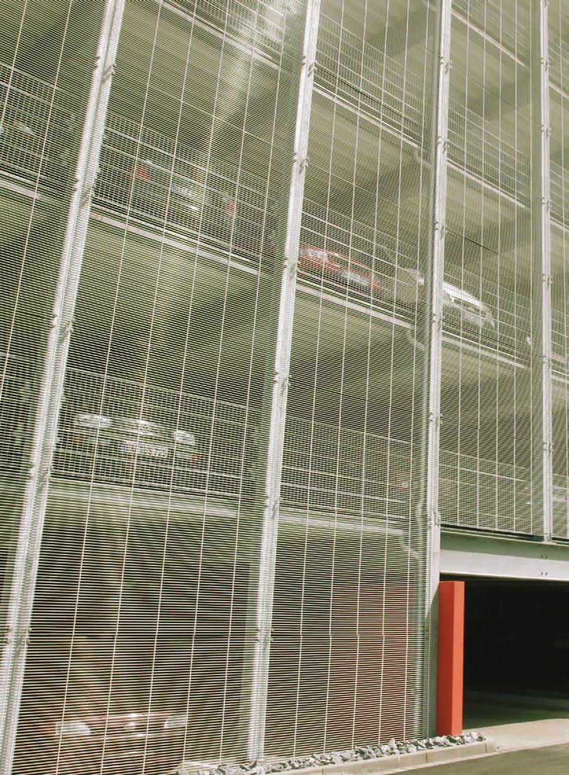
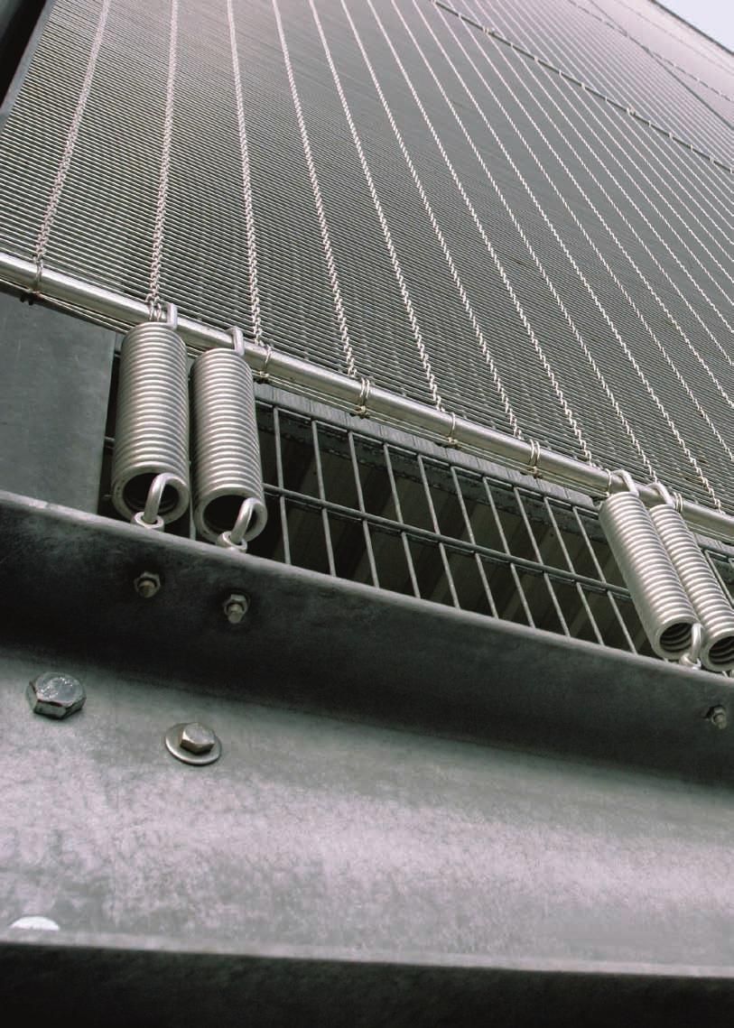
7 1.2 Advantages of steel structures 1.3 Architectural design The advantages of steel structures, namely: l reduced weight of the structure l insensitivity to settlements l elastic deformation behaviour l hinged simple supports result in simplified flat foundations. They also may make deep foundations unnecessary. In case very weak subsoils require deep foundations for controlling the settlements, the design of lightweight steel structures leads to reduced pile lengths. It is a good procedure to wait with the tender until the type of bearing structure is fixed in order to take full advantage of the reduced costs of foundations associated with light steel structures. When designing the façade of a multistorey car park, a major part of the outside walls should remain open (pic ). The design of the façade is used by the architect to make the building fit perfectly in the urban landscape. The use of oblique strips, inclined panels, glazed or perforated units etc. help to break the monotony of prefabricated buildings. Many practical examples of multi-storey car parks are proof of a successful integration of the building in the surrounding environment. When defining the layout of a car park, it is good practice to keep the access lanes as short as possible and to reduce the area occupied by the ramps as much as possible. 5

8

9 2. CAR PARK layout 2.1 How to optimise car park layout? How to optimize parking space? Which loads are applicable in car park design? 12 7
 and the period of occupation (intermittent or continuous).")
10 2.1 How to optimise car park layout? 2. Car park layout The ramp arrangement depends on the type of car park. In this respect, a distinction is made between the duration of occupation (continuous, short or long stay parking) and the period of occupation (intermittent or continuous). The ramps are located inside or outside the building and can be curved or straight. Helical ramps allow faster traffic than straight ramps. The parking access lanes must run along the parking spaces. Distances in the exit direction should be as short as possible. The ramp slope must be less than 15%, ideally below 12%. The slopes of external ramps should be even lower unless appropriate anti-icing measures are taken in winter. A small slope results of course in longer ramps and greater required surface area. On the other hand, wider ramps with gentle slopes add to the comfort of use, an important factor to be considered during design. Car parks with a low overall height and with low storey heights make it possible to shorten the ramps. Another way of reducing ramp lengths while maintaining reasonable slopes is to use the Humy system in which adjacent parking aisles are offset in height by half a storey (fig ).
11 2. Car park layout When the floors are arranged vertically without overlap, this system requires a minimum width of 31 m. For each of the ramp types illustrated (fig ), table shows the required space and the distances for entry and exit routes of a 4-storey building designed according to the Humy system. 72,50 5,00 5,00 52,50 5,00 5,00 5,00 5,00 5,50 10,00 5,50 31,00 72,50 5,00 10,00 7,50 45,00 5,00 5,00 5,00 5,50 10,00 5,50 31,00 2,50 Another project of the same capacity and intermittent occupation shows the performance of an arrangement with external helical ramps. Here, larger area requirements and a more complex construction have however to be taken into account. A: entry and exit ramps adjacent, at the ends of the building, one-way traffic 70,00 7,50 55,00 7,50 5,00 B: ramps at the ends of the building with traffic in both directions 72,50 5,00 22,50 5,00 10,00 5,00 20,00 5,00 5,00 5,50 10,00 5,50 31,00 5,00 5,50 10,00 5,50 5,00 31,00 2,50 2,50 C: entry and exit traffic separated, exit route shortened D: entry and exit traffic mixed, exit route shortened ~20,00 7,50 70,00 55,00 7,50 ~20,00 4,70 21,40 3,50 5,00 5,50 10,00 5,50 31,00 5,00 E: helical ramps on the outside of the building Ramp arrangement Total area of each level [m 2 ] Number of spaces per level Floor area per parking space [m 2 ] Entry [m] Distances Exit [m] A , B , C , D , E , Humy system without and with overlap of half-storeys Ramp arrangement Comparison of entry and exit distances for the ramp arrangements acc. to figure (car park with 4 levels or 8 half-levels) 9


12 2. Car park layout When designing the ramps, it must be ensured that they provide sufficient ground clearance and free height at their top and bottom. Figure shows two ways of dealing with the change of slope. Up to a slope of 12%, the transitions can be made without rounding or intermediate slope n 3 = 0 % R = 20,00 m Generally, the ramp width corresponds to the width of two parking spaces in case of one-way traffic or three spaces with twoway traffic. When the lanes are one-way, it is best to organise traffic for left-hand bends which allow improved visibility for the driver. n 1 = 0 % R = 20,00 m n 2 = 12 % 1 f = 2R t2 = 0,036 m n 2 - n t = R = 1,20 m 2 A: rounded 6 % n 3 = 0 % n 2 = 12 % n 1 + n 2 = 6 % 2 n 1 = 0 % > 4,00 m B: with intermediate slope Ramp slope transitions
13 2.2 How to optimise parking space? 2. Car park layout Ü L B X 1,750 X 2,300 (2,500) Y 4,70 5,00 Y 5,16 3,50 5,16 13,82 2,30 5,48 4,50 5,48 15,46 2, Although cars come in many shapes and sizes, it is possible to arrive at a statistical determination of the space occupied by a typical car. All the basic dimensions of parking spaces, lanes and ramps are fixed on the basis of the car dimensions shown in figure For parking spaces set at various angles against the traffic lanes, the required car park widths are shown in figure A B 2,50 2, When the spaces are set at right angles to the lanes (fig ), they are 5 m long and either 2,30 m or 2,50 m wide, depending on whether the lane has a width of 6,50 m or 5,50 m. The clear span of the steel beams between columns varies from 16,50 m to 15,50 m. 5,00 5,50 5,00 5,00 6,50 5,00 15,50 16,50 90 C 90 D Projection Angle of Width of Area required of width spaces building per parking space of space [ ] [m] [m] [m 2 ] [%] A 45 3,253 13,82 22, B 60 2,656 15,46 20, C 90 2,500 15,50 19, D 90 2,300 16,50 18, Table shows that by arranging the parking spaces at an angle of 45 against the traffic lanes, the width of the building can be reduced to 14 m. If sufficient surface area is available, it is however preferable to arrange the spaces at right angles to the lanes. By doing so, unusable lost space along the lanes and outside walls is minimized. The minimum free height (2,10 m) and the depth of the floor decks add up to the height between the storeys which must be connected by the ramps. 11


. 2.3.")
14 2.3 Which loads are applicable in car park design? 2. Car park layout According to the standard EN :2001, the floor decks must be designed to support a uniform load of 2,5 kn/m 2. For an area up to 12,5 m 2 per parking space, this corresponds to a weight of 3,13 tons, which is significantly heavier than the maximum usual weight for touring cars (1 to 2 tons) In view of their strength and elastic behaviour, car parks in steel are ideally suited for use in seismic areas. (pic ) Mechanical car park, Turkey

15 QVC Düsseldorf Car Park 13
16

17 3. SUITABLE CAR PARK STEEL STRUCTURES 3.1 Columns Floor beams 17 15
.")

18 3.1 Columns 3. Suitable car park steel structures The steel bearing structure consists of vertical columns and horizontal beams, usually connected by bolting (pic ). The horizontal forces due to wind and breaking of cars are transferred horizontally through the floor slabs to the vertical wind bracings or shear walls (e.g. stiff staircases). In multi-storey car parks, the outer columns are spaced at intervals corresponding to the width of one or more parking spaces (units of 2,30 m to 2,50 m). Where the spacing between two columns exceeds 5 m, secondary beams are foreseen between the columns. Ideally, the distance between columns should correspond to the one of the main girders in order to avoid secondary beams, thus optimising the weight of the steel structure. An optical delimitation of the parking spaces is obtained when the distance between columns coincides with the border width of each parking space. In underground car parks, the position of the columns normally depends on the grid of the framework of the building above. In this case, it is important to limit the cross-section of the columns to the strict minimum by using hot-rolled sections or composite columns, which are ideal for this type of construction. For the column sections, it is recommended to choose the steel grade S355 in order both to save weight and to reduce the size of the columns. In large-scale structures, it may be advantageous to choose the high-strength steel S460 featuring a 30% higher yield strength than grade S355. For hot-rolled H-beams over 260 mm in height, steels with a yield strength up to 460 MPa are produced within ArcelorMittal using the particularly economic Quenching and Self-Tempering (QST) rolling process. These steels are commercialized under the brand name of HISTAR Simple beam-column connection using bolted angles Composite steel beam with studs welded in place before erection Design example of a composite floor beam with a construction height of 60 cm.

19 3.2 Floor beams 3. Suitable car park steel structures The choice of the floor beams depends on their span, the type of concrete deck, and the available construction height. The various deck types consist either of cast-in-place concrete, composite or prefabricated concrete slabs. Rolled steel sections in S355 steel with non composite, prefabricated slabs Rolled steel sections in S355 steel with composite slab, poured on site (grade C25/30) l Cast-in-place concrete slabs can be made using temporary formwork or permanent formwork made of prefabricated concrete planks or metal deck. l When using traditional, temporary formwork, the spacing between the steel beams may be freely selected according to the thickness of the concrete slab. However, for economic reasons, this spacing should not exceed 5 m and, in any case, it is a good idea to take advantage of the effect of connecting the rolled steel sections with the reinforced concrete floor. Besides, it is always advisable to take advantage of the composite action between the concrete slab and the steel beam via metal studs welded on the upper flange of the H-section (pic ). Thanks to the composite effect, either savings of about 20% in the steel consumption can be achieved (table 3.2.2) or the construction height can be reduced. Span Steel section spacing l = 16,00 m b = 2,50 m Excess load Q = 2,5 kn/m 2 Slab thickness 100 mm 140 mm G = 7,00 kn/m Q = 6,25 kn/m Ed = 1,35*7,00 + 1,5*6,25 = 18,825 kn/m M = Ed*16 /8 = 602,4 knm G = 9,25 kn/m Q = 6,25 kn/m Ed = 1,35*9,25 + 1,5*6,25 = 21,86 kn/m M = Ed*16 2 /8 = 700 knm Section IPE 500 IPE 400 Gauge M pl.y.rd = 2194*355/(1,1*1000) = 708 knm > 602 knm 100 mm mm = 600 mm The neutral axis lies within the slab: z c = (A a f y /g a )/(b eff 0,85 f ck /g c ) = 77 mm < 140 mm M pl.y.rd = F a *(h a /2+h p +h c -z c /2) = 822 knm > 700 knm 140 mm mm = 540 mm To limit the final deformation, the floor steel sections are given a camber corresponding to a load of G + max 1.3Q b eff 0,85 f ck / c h c +h p h c z c F c h p h a /2 h a h a /2 F a f y / a 17


20 l Self-supporting metal decks from ArcelorMittal Construction in combination with cast-in place concrete avoid investing in the erection of formwork supporting frames, thereby shortening construction time. Depending on the type, the metal decks act solely as formwork or in composite action. Self-supporting metal decks are used for spans up to 3,33 m. In some markets, special metal decks allowing spans up to 5 m without support during the construction phase, are available. In order to limit cracks over the main girders, reinforcing bars have to be foreseen. l Prefabricated concrete planks have thicknesses between 5 to 8 cm and can incorporate the lower reinforcement layer of the concrete deck. Cast-in-place concrete and the upper layer of reinforcement are added on top. Unsupported spans up to 5 m are possible with this system. In case of longer spans, temporary supports may be necessary during construction. l Construction time can be further reduced by using pre-fabricated concrete slabs. These are made in the factory to very tight tolerances and assembled on site using the same lifting machinery as for the erection of the steel structure. Frictional linking of the prefabricated slabs can be provided by fixing with prestressed, high-strength bolts to the upper flange of the steel beams. This method requires very precise construction work. In case of composite action between the prefabricated concrete slabs and the steel beam via metal studs, cope cuts have to be foreseen in the slab at the locations of the studs (pic ). Particular attention has to be paid to the filling of the joints with special mortar. In the case of temporary car parks, non-composite design is usually chosen in combination with beams in high-strength S460 steel. In order to avoid lateral torsional buckling and to transfer horizontal loads, the prefabricated slabs are fixed to the upper flange of the beams. The joints between the slabs are sealed with a permanently elastic material (fig ). Independently from the floor type, the steel beams are typically precambered in the workshop in order to compensate for the deformation resulting from the application of the dead load (weight of the concrete slab and the steel beam) and part of the life load (usually <30%) (pic ). The amount of precamber is determined during static calculation and depends on the inertia of the statical system and the loads. In the unpropped condition, the deflection is calculated considering the statical properties of the steel section only. In the propped condition, the statical properties of the composite section are considered. Here, it is clear that the main girders are supported during the construction phase; thus the deflection from dead load is reduced. S355 steels are usually chosen for the girders. However, savings in material and costs can be achieved by using light-weight IPE sections in high strength S460 steel. In case of restricted construction heights, steel sections with smaller height but slightly heavier weight can be selected Composite action by sealing the joints with special mortar Hilgers system Composite steel sections with camber before placement of the metal decks

21 3.Suitable car park steel structures Span Steel section spacing Prefabricated slab thickness 16,00 m 5,00 m 120 mm Life load 2,50 kn/m 2 Beams in S460 steel can also be used in composite floors. Tables and show the influence of steel grades and composite or non composite design for a span of 16 m. on the construction height and the weight. Grade of steel S235 S355 S460 Section IPE 750x196 IPE 750x147 IPE 600 Height of section (mm) Height ratio 1,02 1,00 0,8 Linear weight of section (kg/m) Linear weight ratio 1,33 1,00 0, Span Steel section spacing Prefabricated slab thickness 16,00 m 5,00 m 140 mm Life load 2,50 kn/m 2 Grade of steel S235 S355 S460 Section IPE 600 IPE 550 IPE 500 Height of section (mm) Height ratio 1,09 1,00 0,91 Linear weight of section (kg/m) Linear weight ratio 1,15 1,00 0, Studs welded through the metal deck on site Comparison between different steel grades for a non composite floor system Comparison between different steel grades for a composite floor system 19
22

23 4. CORROSION AND FIRE PROTECTION OF STEEL STRUCTURES 4.1 Corrosion protection Fire protection/application of the Natural Fire Concept 22 21

 and if effective and permanent ventilation is guaranteed. Nowadays, corrosion protection of steel car park structures is usually achieved by hotdip galvanization.")
24 4.1 Corrosion protection 4.2 Fire protection Application of the Natural Fire Concept According to the regulations of most European countries, there are no fireresistance requirements for steel structures of open multi-storey car parks. A car park is considered open if each storey has openings equal to one third of the total surface area of the outer walls of this level (fig ) and if effective and permanent ventilation is guaranteed. Nowadays, corrosion protection of steel car park structures is usually achieved by hotdip galvanization. During this process, rust and mill scale are removed from the surface of the beam in a pickling bath before immersion during 5-10 minutes in the bath of liquid zinc at 450 C. Typically, a μm thick zinc layer is formed which will protect the steel surface against atmospheric corrosion. In case of severe climatic conditions, an additional paint can be applied on top of the zinc layer. This so-called DUPLEX system minimises maintenance costs and substantially increases the duration of protection against corrosion. The development of new paints has also led to a considerable improvement in corrosion protection. l one or two intermediary coat layers, (thickness 2 x 40 or 1 x 80 μm) l two finishing coat layers (thickness 2 x 60 μm) Apart from the final coat layer, painting is performed in the workshop. After erection, damaged areas are repaired and the final coat layer is applied on site. For more details on the galvanisation process, the brochure, Corrosion protection of rolled steel sections using hot dip galvanisation is available on the website For the countries where there are fire resistance requirements, fire engineering is considered as an alternative to the conventional ISO fire approach which requires passive protection of the steel elements. The data on which the Natural Fire Concept is based (fire load, rate of heat development, number of vehicles involved) have been determined in numerous tests carried out in several countries. Also, statistics from the last decades show that the propagation of fire from a single vehicle has rarely involved more than 3 adjacent vehicles. During real tests (pic ), localised maximum steel temperatures slightly above 700 C were recorded for a short period of time in the unprotected columns and beams. These temperatures did not lead to the collapse or even deformation of the structure (pic ). As a conclusion, fire engineering allows to build unprotected steel structures in open car parks. Experience shows that usual paints provide protection lasting from 10 to 20 years, depending on the atmospheric conditions. At the end of this period, it is usually sufficient to renew the finishing coat, whereby the use of a new colour can be considered to change the outside appearance of the building Unlike open car parks, closed or underground car parks are subject to more stringent fire resistance requirements. Corrosion protection by paints consists of cleaning the surface of the steel section and applying several layers of compatible coats. A typical surface treatment reads as follows: l shot blasting of the surface, degree of purity SA 2.5 l primer 15 to 25 μm


25 4. Corrosion and fire protection of steel structures HE 120 A Roof steel section IPE 400 AA HE 160 B 2780 Here, in order to guarantee the one or two hours ISO fire-resistance, the columns and beams are generally constructed using the composite anti-fire (AF) system in which the chambers between the flanges of the H-sections are filled with reinforced concrete (pic ). These composite columns and beams transmit the loads by the combined action of steel and concrete Floor steel section IPE 500 AA In addition to its load carrying capability, the concrete plays here a role in fire resistance as it protects the encased steel from a rapid rise in temperature. Moreover, this system features good behaviour in case of vehicle impact, thanks to the external location of the steel flanges. A detailed description and software for designing the composite AF columns and beams can be obtained from thel Commercial Sections division of ArcelorMittal and its sales offices Under certain conditions (mechanical ventilation and active fire-fighting measures), the application of the Natural Fire Concept enables passive protection to be omitted for the steel beams of closed or underground car parks Detail of an open multi-storey car park Real fire test carried out on an unprotected steel car park structure, Vernon (France) Steel structure after the fire test, Vernon (France) Detail of floor beams without passive protection in an underground car park 23

26

27 5. DURABILITY OF STEEL STRUCTURES 25

28 The environmental policy of the ArcelorMittal Group aims at sustainable development in view of a long-term balance between environment, social well-being and economy. The long product mills of ArcelorMittal operate according to the requirements of the environmental management system as defined in EN ISO 14001:1996. Most of ArcelorMittal s long product mills use the electric arc process for the steel production. This new technology uses mostly recycled scrap as the base material and allows operating with low primary energy consumption and limited emissions. Steel structures built with our H-sections make it possible to: l reduce the quantity of construction materials by using high-strength steels, l limit transportation thanks to the lower weight of the structural elements, l save construction time by making use of prefabrication, l reduce waste and other nuisances at the job site by using dry assembly methods, l design structures that can be dismantled and reused for other purposes, l increase the usable floor area by favouring high strength S355 or S460 steels, l meet environmental requirements by using recyclable products made from recycled scrap.

29 5. Durability of steel structures Car park Bouillon, Luxembourg 27
30 Technical support & finishing Technical support We are happy to provide you with free technical advice to optimise the use of our products and solutions in your projects and to answer your questions about the use of sections and merchant bars. This technical advice covers the design of structural elements, construction details, surface protection, fire safety, metallurgy and welding. Our specialists are ready to support your initiatives anywhere in the world. To facilitate the design of your projects, we also offer software and technical documentation that you can consult or download from our website: Finishing As a complement to the technical capacities of our partners, we are equipped with high-performance finishing tools and offer a wide range of services, such as: l drilling l flame cutting l T cut-outs l notching l cambering l curving l straightening l cold sawing to exact length l welding and fitting of studs l shot and sand blasting l surface treatment Building & Construction Support At ArcelorMittal we also have a team of multi-product professionals specialising in the construction market: the Building and Construction Support (BCS) division. A complete range of products and solutions dedicated to construction in all its forms: structures, façades, roofing, etc. is available from the website Pictures of QVC Düsseldorf, Düren and Rheda-Wiedenbrück car parks, courtesy of Vollack Management GmbH & Co. KG (Karlsruhe, Germany).
31 Your partner ArcelorMittal Commercial Sections 66, rue de Luxembourg L-4221 Esch-sur-Alzette Luxembourg Tel.: Fax: We operate in more than 60 countries on all five continents. Please have a look at our website under About us to find our local agency in your country. Although every care has been taken during the production of this brochure, we regret that we cannot accept any liability in respect of any incorrect information it may contain or any damages which may arise through the misinterpretation of its contents.
32 ArcelorMittal Commercial Sections 66, rue de Luxembourg L-4221 Esch-sur-Alzette LUXEMBOURG Tel.: Fax:
ArcelorMittal Europe - Long Products Sections and Merchant Bars. Office Building ArcelorMittal in Esch Alzette
 ArcelorMittal Europe - Long Products Sections and Merchant Bars Office Building ArcelorMittal in Esch Alzette Location the country, at the heart of the iron and steel region. It has good access to the
Newton Group CANADACAR SYSTEM. Basic Construction of the CANADACAR System. CANADACAR Module Format
 Basic Construction of the CANADACAR System The CANADACAR System is a prefabricated, engineered and constructed freestanding parking garage structure that utilizes superior technology combining pre-cast
STEEL STRUCTURAL SYSTEMS
 STEEL STRUCTURAL SYSTEMS Steel elements are of two basic types: Structural steel shapes are formed into their final shapes by hot-rolling. This method produces such common elements as wide flange sections,
Angelina Predesign charts
 Angelina Predesign charts The predesign charts allow the designer to get a quick and easy answer concerning the right section to use in his project. The charts are made for non-composite and composite
A-BEAM W Erection Manual 2
 2 BEAM W Revision 6/2017 Finland 3 TABLE OF CONTENTS 1 ERECTION INSTRUCTIONS... 4 1.1 A-BEAM W... 4 1.2 Codes and standards to be followed during erection... 4 1.3 Documents to be followed in erection
Hollowcore Floors. The ideal structural floor solution for all building types in all sectors.
 Hollowcore Floors Hollowcore Floors The ideal structural floor solution for all building types in all sectors. 2 3 System Overview Prestressed hollowcore units form part of the comprehensive range of precast
Introduction. Structures may be classified on the basis of materials used for construction, as follows: Steel structures. Aluminium structures
 Steel Structures 1 Introduction Structures may be classified on the basis of materials used for construction, as follows: Steel structures Aluminium structures Concrete structures Composite structures
Pro-Con Structural Study of Alternate Floor Systems
 Andrew Covely Structural Dr. Linda Hanagan The Helena New York City, NY October 27, 2004 Pictures courtesy of Fox & Fowle Architects Pro-Con Structural Study of Alternate Floor Systems Executive Summary
FORMDECK. constructions. constructions
 FORMDECK constructions constructions Introduction Formdeck300 (FD300) is a very efficient and durable permanent metal tray formwork, reinforcement and ceiling system used for suspended concrete slab construction.
Comparative Study of R.C.C and Steel Concrete Composite Structures
 RESEARCH ARTICLE OPEN ACCESS Comparative Study of R.C.C and Steel Concrete Composite Structures Shweta A. Wagh*, Dr. U. P. Waghe** *(Post Graduate Student in Structural Engineering, Y.C.C.E, Nagpur 441
The most economical solutions can be obtained by using our load span tables, and where applicable dimensioning software for roof optimisation.
 Roof Decking: RD60 Firth Steels manufacture and supply various types of structural roof deck profiles, each characterised by the depth of each profile which lends itself in its design to various characteristics
CHAPTER 1 INTRODUCTION
 CHAPTER 1 INTRODUCTION 1.0. GENERAL Modern civilization relies upon the continuing performance of civil engineering infrastructure ranging from industrial building to power station and bridges. For the
Structural Steel Products UK & Ireland. Multideck Technical Handbook
 Structural Steel Products UK & Ireland Multideck Technical Handbook 2 Structural Steel Products Multideck Multideck Structural Steel Products 3 4 Structural Steel Products Multideck Contents Multideck
Sustainably produced hot-rolled sections in sustainable buildings
 Sustainably produced hot-rolled sections in sustainable buildings Lucien Weber, MSc 1 Charles Werner, MSc 2 1 Arcelor Europrofil. 66, rue de Luxembourg. 4221 Esch-sur-Alzette.Luxembourg Phone:+352 5313
Multideck 146. Contents
 Contents Specification and Design 55 Load Tables 57 Fire Performance 60 Sound Attenuation 63 Concrete Volume Savings composite steel deck is optimised to minimise the concrete volumes on longer spans providing
Anchor bolts ASTM F1554, Gr. 36 Wide flange beams ASTM A992, Fy = 50 ksi Misc. structural steel ASTM A36, Fy = 36 ksi
 STRUCTURAL NOTES MATERIAL STRENGTHS Structural Steel Reinforcing Steel Concrete Masonry Structural Lumber Anchor bolts ASTM F1554, Gr. 36 Wide flange beams ASTM A992, Fy = 50 ksi Misc. structural steel
VARIOUS TYPES OF SLABS
 VARIOUS TYPES OF SLABS 1 CHOICE OF TYPE OF SLAB FLOOR The choice of type of slab for a particular floor depends on many factors. Economy of construction is obviously an important consideration, but this
THE FORENSIC MEDICAL CENTER
 THE FORENSIC MEDICAL CENTER Image courtesy of Gaudreau, Inc. TECHNICAL REPORT #2 OCTOBER 26, 2007 KEENAN YOHE STRUCTURAL OPTION DR. MEMARI FACULTY ADVISOR EXECUTIVE SUMMARY Image courtesy of Gaudreau,
Installing DELTABEAM. Installation of DELTABEAM. Deliveries. Storage on-site
 Installing DELTABEAM Installation of DELTABEAM These DELTABEAM installation instructions are intended to complement the project s erection plan. Peikko s technical support can help with the erection plan
A-BEAM S Erection Manual 2
 2 A-BEAM S Revision 6/2017 Finland 3 TABLE OF CONTENTS 1 ERECTION INSTRUCTIONS... 4 1.1 A-BEAM S... 4 1.2 Codes and standards to be followed during erection work... 4 1.3 Structural plans to be followed
The Structural Redesign of Boyds Bear Country and its Related Systems. Boyds Bear Country, Pigeon Forge, Tennessee
 The Structural Redesign of Boyds Bear Country and its Related Systems Included in this Presentation: Background and Existing System Proposal Problem / Solution Structural System Redesigns Pre-cast Concrete
SOLOBLOC HINGED LIFT ASSISTED, SINGLE PERSON OPERATION HSE COMPLIANT CPH8 MULTIPLE LEAF
 HINGED LIFT ASSISTED, SINGLE PERSON OPERATION HSE COMPLIANT CPH8 MULTIPLE LEAF All Solobloc units are post galvanised in excess of BS EN 1461. Post Galvanised coating thickness is available in 3 grades
BEARING METAL STUD FRAMING
 L-1 Section 05410 Long Form Specification LOAD BEARING METAL STUD FRAMING This section includes axially loaded steel studs, with unique slotted top channels, usually of 0.91, 1.2 and 1.5 mm (16, 18, or
SPECIFICATION FOR REINFORCED SOIL WALL
 SPECIFICATION FOR REINFORCED SOIL WALL 1.0 EXTENT OF WORK The work shall consist of Reinforced Soil walls built in accordance with this specification and in conformity with the lines, levels and details
SECTION PLATE CONNECTED WOOD TRUSSES
 SECTION 06173 PLATE CONNECTED WOOD TRUSSES PART 1 GENERAL 1.01 SUMMARY A. Section Includes: 1. Shop fabricated wood trusses for roof and floor framing. 2. Bridging, bracing, and anchorage. B. Related Sections:
Technical Manual. The difference is.
 Technical Manual The difference is www.rlsd.com innovation, commitment, support. 2 www.rlsd.com For a service with a difference, choose Richard Lees Steel Decking, the UK specialist steel decking company
The difference is Guidance for the preparation of Deck Manufacturing Schedules
 The difference is Guidance for the preparation of Deck Manufacturing Schedules innovation, commitment, support. 2 Guidance for the preparation of Deck Manufacturing Schedules Minimum Requirements for Schedule
Exterior Wall Solutions Building Shell
 A strong, water tight and thermally insulated building shell will ensure the buildings sustainability of usage over time. The Exterior Shell is the most important factor of protection to ensure that the
Reinforced concrete double walls
 Reinforced concrete double walls HOW YOUR BUILDING WORKS TAKES PLACE FASTER WHILE YOUR COSTS REMAIN LOW DOUBLE WALLS Strength in building technology The Kerkstoel reinforced double walls consist of two
Features and Benefits
 KingFlor KF40 Features and Benefits Fielders KF40 is a revolutionary steel formwork solution suitable for concrete slabs in all types of construction. KF40 combines the performance of a traditional flat
PASSAIC COUNTY TECHNICAL INSTITUTE CCA 1422 NEW S.T.E.M. BUILDING 2017
 SECTION 053100 STEEL DECKING PART 1 - GENERAL 1.1 RELATED DOCUMENTS A. Drawings and general provisions of the Contract, including General and Supplementary Conditions and Division 01 Specification Sections,
Sabah Shawkat Cabinet of Structural Engineering 2017
 3.1-1 Continuous beams Every building, whether it is large or small, must have a structural system capable of carrying all kinds of loads - vertical, horizontal, temperature, etc. In principle, the entire
Level 6 Graduate Diploma in Engineering Structural analysis
 9210-111 Level 6 Graduate Diploma in Engineering Structural analysis Sample Paper You should have the following for this examination one answer book non-programmable calculator pen, pencil, ruler, drawing
Metal Decking Specialists
 Metal Decking Specialists Technical Design. Manual Manufacture. and Guidance Installation. Notes Contents Introduction 03 Introduction 04 SMD Product Selector Technical and Design Support 05 How can SMD
Crossroads at Westfields Building II
 Crossroads at Westfields Building II Chantilly, Va STEPHEN LUMPP Structural option Faculty Consultant: Dr. Andres Lepage Technical Report 2 EXECUTIVE SUMMARY This report is a study of alternate floor systems
Reinforced concrete double walls
 Reinforced concrete double walls Build faster, pay less. Strength in building technology Uses The Kerkstoel reinforced double walls consist of two slabs of reinforced concrete joined to each other by lattice
Cantilever Racking. Cantilever Racking
 Cantilever Racking Cantilever Racking Cantilever raking is specially designed to store long or varying length items, such as metal beams, pipes, moulding, wooden boards, metal and plastic sheets among
SECTION COLD-FORMED METAL FRAMING
 SECTION 05 40 00 COLD-FORMED METAL FRAMING SPEC WRITER NOTE: Delete between //---// if not applicable to project. Also delete any other item or paragraph not applicable in the section and renumber the
Prestressed Hollowcore Slabs PRECAST CONCRETE SOLUTIONS.
 PRECAST CONCRETE SOLUTIONS Prestressed Hollowcore Slabs HOLLOWCORE: THE CONCEPT Hollowcore slabs are prestressed concrete elements that have a constant cross section. They are manufactured using high tensile
Union County Vocational - Technical Schools Scotch Plains, New Jersey
 SECTION 092216 - NON-STRUCTURAL METAL FRAMING PART 1 - GENERAL 1.1 RELATED DOCUMENTS A. Drawings and general provisions of the Contract, including General and Supplementary Conditions and Division 01 Specification
Technical Report #2. Matthew R Peyton
 Technical Report #2 This Document is Technical Report #2 for 5th year senior thesis in the Architectural Engineering Departments at The Pennsylvania State University. This Report is to prepare a study
3.4.2 DESIGN CONSIDERATIONS
 3.4.2 DESIGN CONSIDERATIONS Formwork Where Flatdeck sheet is used as formwork, the profile provides resistance to wet concrete (G) and construction loads (Q). Maximum formwork spans given in Section 3.4.4.1
Austral Deck Design for Construction Loading. Permanent formwork and Span capability
 Austral Deck Design for Construction Loading Permanent formwork and Span capability Introduction The purpose of this document is to demonstrate the process of designing Austral Deck as formwork complying
Demidec. cornish concrete products Demidec Flooring and Permanent Formwork
 Demidec cornish concrete products Demidec Flooring and Permanent Formwork Demidec What is Demidec? Demidec is a thin precast concrete plate, typically 60mm deep, although this can vary depending on the
ABS Pre-Fab Building S ystem
 INTRODUCTION Accumech Building System P. Ltd. provides best quality profiled Roofing, Ceiling and Pre-engineered Building System. The demand in the market and due to our services and goodwill in the market,
COMPOSITE BRIDGES WITH PRECAST CONCRETE SLABS
 COMPOSITE BRIDGES WITH PRECAST CONCRETE SLABS P. SCHAUMANN Univ.-Prof. Dr.-Ing. J. UPMEYER Dipl.-Ing. University of Hanover Institute for Steel Construction Appelstraße 9A 30167 Hanover / Germany Tel.:
HOLORIB /SUPERHOLORIB
 A Tata Steel Enterprise HOLORIB /SUPERHOLORIB Composite profiles made of steel sheathing, reinforcement and fire protection 2 STEEL. COMPOSITE. HOLORIB / SUPERHOLORIB. COMPOSITE FLOOR DECK HOLORIB and
SECTION COMPOSITE METAL DECKING
 PART 1 GENERAL 1.1 DESCRIPTION SECTION 05 36 00 1. Use this section only for NCA projects. 2. Delete between // ---- // if not applicable to project. Also delete any other item or paragraph not applicable
SECTION ORNAMENTAL WELDED STEEL FENCING
 SECTION 032300 ORNAMENTAL WELDED STEEL FENCING PART 1 - GENERAL 1.1 RELATED DOCUMENTS A. Drawings and general provisions of the Contract, including General and Supplementary Conditions and Division 01
SECTION STEEL DECKING
 SECTION 05 31 00 STEEL DECKING SPEC WRITER NOTE: 1. Delete text between // // not applicable to project. Edit remaining text to suit project. 2. Refer to Section 05 36 00, COMPOSITE METAL DECKING for floor
Brochure All Solutions at a Glance. All Solutions. All Solutions at a Glance. v2013/10en
 Brochure All Solutions at a Glance All Solutions All Solutions at a Glance v2013/10en Scaffolding, formwork, and shoring There s always a solution 02 The product range at Scafom-rux is extensive, very
Contents. 01 Introduction Key Design Factors. 03 Floor Systems. 04 Special Floor Systems Beam Connections.
 Best Practice in Steel Construction - Commercial Buildings Contents The Steel Construction Institute (SCI) develops and promotes the effective use of steel in construction. It is an independent, membership
SPECIFICATION FOR TUBULAR STEEL LIGHTING COLUMN. Reference is made in this Specification to the following:
 SPECIFICATION FOR TUBULAR STEEL LIGHTING COLUMN 1. SCOPE This specification covers the design, fabrication and testing of tubular section, galvanised steel friction fit jointed street light columns of
STEEL DESIGNERS MANUAL
 STEEL DESIGNERS MANUAL SIXTH EDITION The Steel Construction Institute Edited by Buick Davison Department of Civil & Structural Engineering, The University of Sheffield Graham W. Owens Director, The Steel
Section 713. BRIDGE REHABILITATION STEEL
 713.01 Section 713. BRIDGE REHABILITATION STEEL 713.01. Description. This work consists of repairing and replacing portions of structural steel bridges. A redundant structure consists of supporting elements
SECTION COLD-FORMED METAL TRUSSES
 SECTION 054400 COLD-FORMED METAL TRUSSES PART 1 - GENERAL 1.1 RELATED DOCUMENTS A. Drawings and general provisions of the Contract, including General and Supplementary Conditions and Division 01 Specification
Lattice Plate Flooring
 Lattice Plate Flooring Introduction Pekso Precast manufacturers and supplies a range of precast concrete structural building products ranging from foundations and flooring systems that includes Lattice
SECTION METAL STAIRS
 SECTION 05510 METAL STAIRS PART 1 GENERAL 1.01 SECTION INCLUDES A. Stairs with concrete treads. B. Stairs with metal treads. C. Structural steel stair framing and supports. D. Handrails and guards. 1.02
Features and Benefits
 KingFlor KF57 Features and Benefits Fielders KF57 is a steel formwork solution suitable for composite concrete slabs in concrete and steel framed construction. KF57 is a light, easy to use, steel decking
HOLLOW CORE FLOORS SPEED AND STRENGTH
 HOLLOW CORE FLOORS SPEED AND STRENGTH CONTENTS 2 3 4 5 7 8 9 10 12 13 14 INTRODUCTION PRECAST CONCRETE FLOORS T HE A DVANTAGES BISON HOLLOW CORE FLOORS BEARINGS FALSE CEILINGS AND SOFFIT FIXINGS BISON
INSTALLATION. General. Important Note. Design. Transport
 General The roof trusses you are about to install have been manufactured to precise engineering standards. To ensure that the trusses perform as designed, it is essential that they be handled, erected
Structural Products. Multideck 50-V3 Galvanised Steel Floor Decking System
 Structural Products & Systems Multideck Multideck 50-V3 Galvanised Steel Floor Decking System Meadowhall Extension, Sheffield UK. Image courtesy of MSW (UK) Ltd. 2 Introduction Structural Products & Systems,
Do you want more performant safety barriers?
 Do you want more performant safety barriers? 3 ArcelorMittal Flat Carbon Europe : committed to safety, sustainability and competitiveness 5 ArcelorMittal s High Strength Low Alloy (HSLA) steels increase
SECTION 15 STRUCTURAL STEEL
 SECTION 15 STRUCTURAL STEEL 1 GENERAL 1.1 SCOPE Outline description This section applies to the provision, fabrication, treatment, erection and connection of structural steelwork. 1.2 CROSS REFERENCES
Temecula Medical Center Temecula, CA
 Temecula Medical Center Temecula, CA Technical Assignment #2 Sean F. Beville The Pennsylvania State University Architectural Engineering Structural Option Senior Thesis Project Student Advisor: Thomas
Steel fibres Structural applications
 WireSolutions Steel fibres Structural applications TAB-Slab TAB-Structural TAB-Deck TAB-Raft ArcelorMittal & WireSolutions Transforming tomorrow ArcelorMittal ArcelorMittal is the world leader in the steel
Structural Technical Report #2 Pro/Con Study of Alternate Floor Systems
 Christopher McCune Structural Option Eight Tower Bridge Faculty Advisor: Dr. Hanagan October 31 st, 2005 Structural Technical Report #2 Pro/Con Study of Alternate Floor Systems Executive Summary This technical
SECTION (formerly 05425) PRE-ENGINEERED, PRE-FABRICATED COLD-FORMED STEEL ROOF & FLOOR TRUSSES
 PRE-ENGINEERED, PRE-FABRICATED COLD-FORMED STEEL ROOF & FLOOR TRUSSES") SECTION 05 44 00 (formerly 05425) PRE-ENGINEERED, PRE-FABRICATED COLD-FORMED STEEL ROOF & FLOOR TRUSSES PART 1 GENERAL 1.1 SUMMARY A. Section includes pre-engineered, pre-fabricated cold-formed steel framing
SECTION 05 44 00 (formerly 05425) PRE-ENGINEERED, PRE-FABRICATED COLD-FORMED STEEL ROOF & FLOOR TRUSSES PART 1 GENERAL 1.1 SUMMARY A. Section includes pre-engineered, pre-fabricated cold-formed steel framing
DIVISION 5 - STRUCTURAL STEEL AND IRON WORK
 DIVISION 5 - STRUCTURAL STEEL AND IRON WORK SECTION 05100 STRUCTURAL METAL FRAMING PART 1.00 GENERAL 1.01 SCOPE OF WORK A. Work Included: 1. 2. Structural steel complete in place. Steel joists complete
Contents. Tables. Notation xii Latin upper case letters Latin lower case letters Greek upper case letters Greek lower case letters. Foreword.
 Tables x Notation xii Latin upper case letters Latin lower case letters Greek upper case letters Greek lower case letters xii xiv xvi xvi Foreword xviii 1 Introduction 1 1.1 Aims of the Manual 1 1.2 Eurocode
Structural Comparison between Pan Joist Concrete and Steel Frame Systems for UMCP Student Housing Building B
 Structural Comparison between Pan Joist Concrete and Steel Frame Systems for UMCP Student Housing Executive Summary The proposed thesis will include an investigation of two different alternative structural
K. ASTM F436- Standard Specification for Hardened Steel Washers; 2011.
 DIVISION 05 METALS 05 12 00 STRUCTURAL STEEL FRAMING PART 1 GENERAL 1.1 SECTION INCLUDES A. Structural steel framing members, support members. 1.2 RELATED REQUIREMENTS A. Section 05 50 00 - Metal Fabrications:
Concrete Design Guide
 Number 7 38 TheStructuralEngineer Technical July 2015 Post-tensioned slabs Concrete Design Guide No. 7: Design of post-tensioned slabs This series is produced by The Concrete Centre to enable designers
DECK DAMAGE AND PENETRATIONS
 DECK DAMAGE AND PENETRATIONS Prepared By Richard B. Heagler, P.E. SDI CONSULTANT Copyright 1987 (Rev. 2000) All rights reserved P.O. Box 25 Fox River Grove, IL 60021 Phone: (847) 458-4647 Fax: (847) 458-4648
Schöck Isokorb type KS
 Schöck Isokorb type Schöck Isokorb type Fig. 1: Schöck Isokorb type Schöck Isokorb type Suitable for cantilevered steel balconies and canopies. It transfers negative moments and positive shear forces.
DICTATOR Lift Shaft System
 DICTATOR Lift Shaft System The Modular Lift Shaft System, also for Retrofitting Certified According to EN 1090 A lift is becoming more and more important for daily life, not only in newly constructed buildings
SECTION FABRICATED ENGINEERED STRUCTURES. A. Pre-engineered, shop-fabricated structural steel building with formed purlin framing.
 PART 1 GENERAL 1.1 RELATED DOCUMENTS SECTION 13 34 00 FABRICATED ENGINEERED STRUCTURES A. Drawings and general provisions of the Contract, including General and Supplementary Conditions and Division 1
SECTION PRE-ENGINEERED COLD-FORMED METAL ROOF AND FLOOR TRUSSES
 SECTION 05440- PRE-ENGINEERED COLD-FORMED METAL ROOF AND FLOOR TRUSSES PART 1 GENERAL 1.01 SUMMARY A. Section includes pre-engineered, pre-fabricated cold formed steel framing elements. Work includes:
INFLUENCES OF ADVANCED COMPOSITE MATERIALS ON STRUCTURAL CONCEPTS FOR BRIDGES AND BUILDINGS. Introduction. Bridges
 INFLUENCES OF ADVANCED COMPOSITE MATERIALS ON STRUCTURAL CONCEPTS FOR BRIDGES AND BUILDINGS Prof. Dr. Thomas Keller Swiss Federal Institute of Technology, Lausanne, Switzerland Introduction The consideration
Miller Collective Safety at Height Solutions EPIC ULTRA Barrier System EPIC Post-N-Barrier System EPIC Basic Barrier System
 For over 65 years the Miller brand has been synonymous with personal fall protection products and services. As the global leader in safety at height solutions, Honeywell Safety Products introduces a new
WYDZIAtUARCHiTE TORY WELDED STEEL CONSTRUCTIONS IN POLAND IN 1934.
 0 1 D L J 0 T EZ K A WYDZIAtUARCHiTE TORY P_p li t P r. h r,,;, i ijtgg n ^ s k i e j /g? WELDED STEEL CONSTRUCTIONS IN POLAND IN 1934. BY STEFAN BRYfcA, C.E., D.ENO. (PROFESSOR AT THE TECHNICAL COLLEGE
Concrete Framing Systems - Walls and Columns
 Concrete Framing Systems - Walls and Columns Casting a Concrete Wall Wall Footing Reinforcing Wall Forms Pouring Concrete Finishing the Concrete Controlling Cracking Insulating Concrete Forms (ICF) Tilt-Up
WITH ROLLED SECTIONS. Sections
 BRIDGES WITH ROLLED SECTIONS Sections Bridges with rolled sections There are numerous partners involved when planning the construction of a new bridge. These include: - the decision-making bodies, - the
Kaleida Health Global Heart and Vascular Institute University at Buffalo CTRC/Incubator. Buffalo, New York. Technical Report #2
 University at Buffalo CTRC/Incubator Buffalo, New York William McDevitt October 27, 2010 Table of Contents Executive Summary...3 Introduction...4 Structural System Overview...5 Foundation...5 Floor System...5
SECTION COMPOSITE METAL DECKING
 PART 1 GENERAL 1.1 DESCRIPTION: SECTION 05 36 00 COMPOSITE METAL DECKING SPEC WRITER NOTE: Delete between // // if not applicable to project. Also delete any other item or paragraph not applicable in the
SECTION PRE-ENGINEERED METAL BUILDING
 SECTION 13121 PRE-ENGINEERED METAL BUILDING PART 1 GENERAL 1.01 SCOPE OF WORK A. Furnish all labor, materials, equipment and incidentals required to design, fabricate, deliver to project site, and erect
A key consideration when specifying a composite steel deck floor is durability and more specifically, the life to first maintenance (LTFM).
.") SMD Structural Floor and Roof Solutions Technical Guidance Sheet Durability of Steel Deck Composite Floors Introduction SMD (Structural Metal Decks Ltd), have supplied and installed millions of square
SMD Structural Floor and Roof Solutions Technical Guidance Sheet Durability of Steel Deck Composite Floors Introduction SMD (Structural Metal Decks Ltd), have supplied and installed millions of square
Recommendations for additional fire protection of structural elements
 ANNEX 6 Recommendations for additional fire protection of structural elements 1 Scope This Annex contains a series of recommendations applicable to structural concrete structures which, for general fire
Trench Sheeting CONSTRUCTION
 Trench Sheeting CONSTRUCTION Trench Sheeting Introduction DESIGNED TO SUPPORT Tata Steel Construction Products are a leading manufacturer of trench sheeting in the UK. All sheets are exclusively manufactured
Comparative Study on Analysis and Cost of R.C.C. and Steel-Composite Structure
 Comparative Study on Analysis and Cost of R.C.C. and Steel-Composite Structure Renavikar Aniket V. 1, Suryawanshi Yogesh 2 1 Dept. of Civil Engineering ICOER Wagholi Pune 2 Professor, Department of Civil
DESIGN OF HIGH-RISE MODULAR OPEN BUILDINGS
 O&SB2010 Open and Sustainable Building Chica, Elguezabal, Meno & Amundarain (Eds.) 2010, Labein -TECNALIA. ISBN 978-84-88734-06-8 DESIGN OF HIGH-RISE MODULAR OEN BUILDINGS Lawson, Mark R SCI rofessor of
Advantages. - They are quick, clean and. sizes, floor types and construction systems mean the mezzanines can be adapted to meet specific client needs.
 Mezzanine Floors Mezzanine floors enable the working height of a space to be utilised to its full potential by doubling or tripling the surface area. They can be designed as storage areas, changing rooms
1. Base plates, setting plates and anchor rods for columns. 8. Lintels if connected to structural steel columns.
 PAGE 051200-1 SECTION 051200 PART 1 - GENERAL 1.1 RELATED DOCUMENTS A. Drawings and general provisions of the Contract, including General and Supplementary Conditions and Division 01 Specification sections,
Analysis 2 Pre-fabricated Metal Stud Crete Panels-Structural Breadth
 Analysis 2 Pre-fabricated -Structural Breadth Background The current façade design calls for stick built 3-5/8 masonry on a 7-5/8 metal stud back-up with exterior sheathing board, 1 cavity board insulation
one structural behavior, systems, and design ARCHITECTURAL STRUCTURES: FORM, BEHAVIOR, AND DESIGN DR. ANNE NICHOLS SUMMER 2015 lecture
 ARCHITECTURAL STRUCTURES: FORM, BEHAVIOR, AND DESIGN DR. ANNE NICHOLS SUMMER 2015 lecture one structural behavior, systems, and design Introduction 1 www.greatbuildings.com Syllabus & Student Understandings
ARCHITECTURAL SPECIFICATIONS
 ARCHITECTURAL SPECIFICATIONS I. GENERAL 1. System Description: 1.1 Size The raised access floor system shall consist of 600mm x 600mm x 3mm modular steel cement panels/ cementitious panels / cement filled
AREMA 2008 Annual Conference. LOW PROFILE RAILROAD BRIDGE Steve K. Jacobsen, PE NNW, Inc. Rochester, Minnesota
 AREMA 2008 Annual Conference LOW PROFILE RAILROAD BRIDGE Steve K. Jacobsen, PE NNW, Inc. Rochester, Minnesota 55904 507-281-5188 Steve K. Jacobsen, PE 2 LOW PROFILE RAILROAD BRIDGE Steve K. Jacobsen, PE
TRITEC light Steel Panel Formwork
 TRITEC light Steel Panel Formwork Perfection made in Germany Various practical illustrations of TRITEC Panel Combinations Guaranteed the largest possible range of sizes with the least possible amount of
Jonathan R. Torch Technical Report 2 Columbia University. Technical Report 2. Pro-Con Structural Study of Alternate Floor Systems
 Technical Report 2 Pro-Con Structural Study of Alternate Floor Systems Columbia University Broadway & 120 th Street, New York, NY Jonathan R. Torch Pennsylvania State University Architectural Engineering
A. Product Data: For each type of cold-formed steel framing product and accessory.
 SECTION 05400 - COLD-FORMED METAL FRAMING PART 1 - GENERAL 1.1 SUMMARY A. Section Includes: 1. Exterior non-load-bearing wall framing. 1.2 ACTION SUBMITTALS A. Product Data: For each type of cold-formed