Venice Biennale 2013 Sandbag Installation
|
|
|
- Everett Johnston
- 6 years ago
- Views:
Transcription
1 Venice Biennale 2013 Sandbag Installation Details of sandbag wall load testing and construction proposals Project number: March 2013 Sheraton House Cambridge CB3 0AX Tel

2 Contents Introduction Project Team Project Evolution Summary of Structural Design Recommendations Description of Sandbag Wall Testing Results from Sandbag Wall Testing Discussion of Results Structural Design Recommendations Appendices Appendix A Engineering sketches Appendix B Photos from Test Panel Build Process Appendix C Photos from Test Panel Load Testing Appendix D Results from Test Panel Load Testing Report Authors Simon Smith Smith and Wallwork Michael Ramage University of Cambridge Report Revision History Author Description Date Ref Simon Smith First issue 15/03/ SaW_Venice Biennale_Sandbag Wall Load Testing_March 2013 Page 2
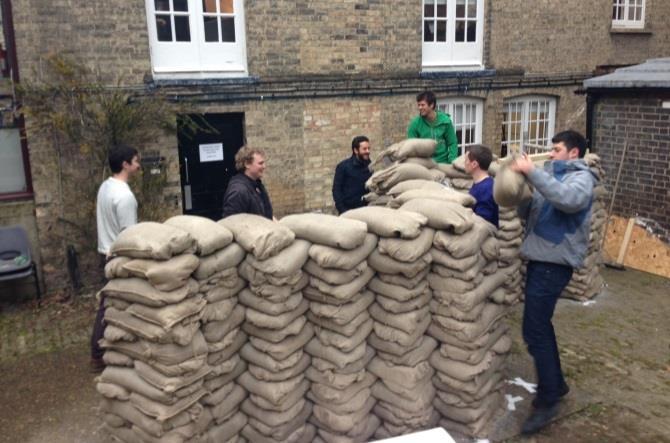
3 Introduction This report has been compiled to provide information on the results of sandbag wall load testing and construction proposals for a sandbag installation conceived by Roz Barr Architects for the Venice Biennale The structural stability of the sandbag walls is discussed and options are proposed to achieve a structurally safe and robust installation. The report will cover the evolution of the design, load testing carried out at Cambridge University and construction proposals. Project Team The project is led by Roz Barr Architects. The structural design of the sandbag walls is a joint venture between the architecture department at Cambridge University and engineering consultant, Smith and Wallwork. The construction of the sandbag test panel was carried out by the Architecture Masters Degree students at Cambridge University. The construction of the final sandbag installation will be carried out by an Italian contractor in collaboration with Roz Barr Architects. Architect and Lead Designer: Roz Barr and Emma Tubbs, Roz Barr Architects Structural Engineer: Simon Smith, Smith and Wallwork Structural Engineer: Michael Ramage and Emily So, University of Cambridge Structural Testing and Construction: Architecture Masters Degree students at Cambridge University Project Evolution The project was conceived by Roz Barr Architects who had previously designed and constructed a successful sandbag installation in central London as part of the 2012 London Festival of Architecture. The plans for the Venice Biennale 2013 sandbag installation differ from the London project; it uses a sandbag floor and 2.5m tall sandbag walls to create a courtyard space approximately 51m x 13m. Some 17,000 sandbags will be required to complete the installation. From an early stage the importance of the stability of the sandbag walls was recognised and the design was influenced by this consideration; hence the saw-tooth profile of the main walls on plan. From the experience gained at the 2012 London Festival of Architecture it was known that a test panel build would prove useful in terms of providing data on buildability and structural stability. SaW_Venice Biennale_Sandbag Wall Load Testing_March 2013 Page 3
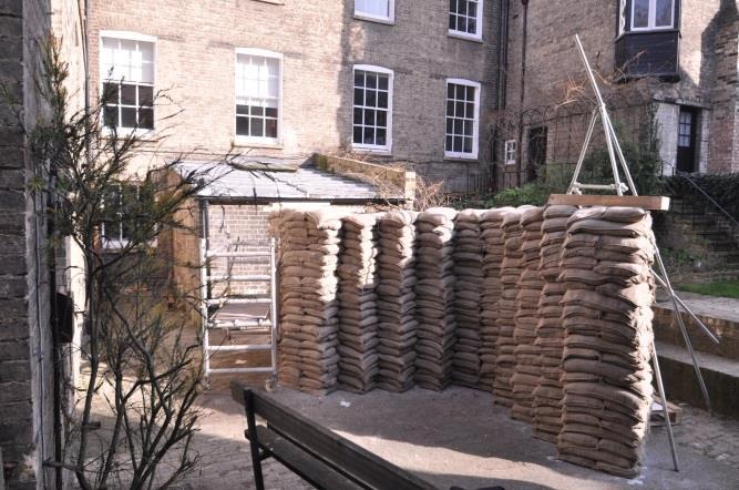
4 Summary of Structural Design Recommendations The sandbag wall load testing carried out at Cambridge University has provided extensive structural performance data. This data allows a structural design to be completed for the proposed Venice Biennale installation. It is proposed that the sandbag walls are designed to resist a horizontal loading of 3.0kN/m in areas of potential crowd loading (ie entry and exit points) and 1.5kN/m in all other areas. For the purposes of design this load would be applied at 1.1m above ground level. The minimum factor of safety against collapse should be 2.0. Using these design loads and the data from the load test completed it will be necessary to provide reinforcement to certain areas of the sandbag wall; adjacent the openings and in the flat walls at each end of the installation. The reinforcement proposed is a form of vertical pre-stressing similar to that trialled during the load tests. A metal bar is concealed in the depth of the wall or pier and is fixed to a baseplate and top plate. A pre-stress of 0.85kN is introduced and maintained using a head spring or regular pre-stress visits. Details of this pre-stressing can be seen in appendix A and further information associated with the reinforcement can be found in this report in the section titled Structural Design Recommendations. Description of Sandbag Wall Testing A sandbag wall test panel was built at Cambridge University Architecture Department during March The test panel layout was chosen to incorporate the saw-tooth profile of the main walls and comprised three wall panels and four piers that formed a test sample that was 2.0m tall and 5.1m x 1.8m on plan constructed from approximately 400 sandbags. On completion of the test panel construction it was evident that the massive nature of the wall and the saw-tooth profile provided a structure that was extremely robust within the central portion. Initial horizontal push tests detected almost no movement in these central portions and it was decided to concentrate all testing at the wall ends, in particular to test the piers that formed the wall ends. A series of load tests were devised including monitoring and recording of structural behaviour. The tests carried out on the panel included static, dynamic and push-over scenarios. Monitoring comprised recording loads applied, horizontal deflection and recovery and accelerometers were place on top of the wall to record data during the dynamic load tests. SaW_Venice Biennale_Sandbag Wall Load Testing_March 2013 Page 4

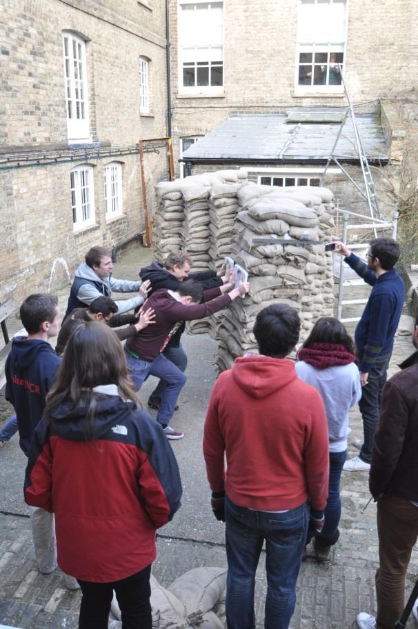
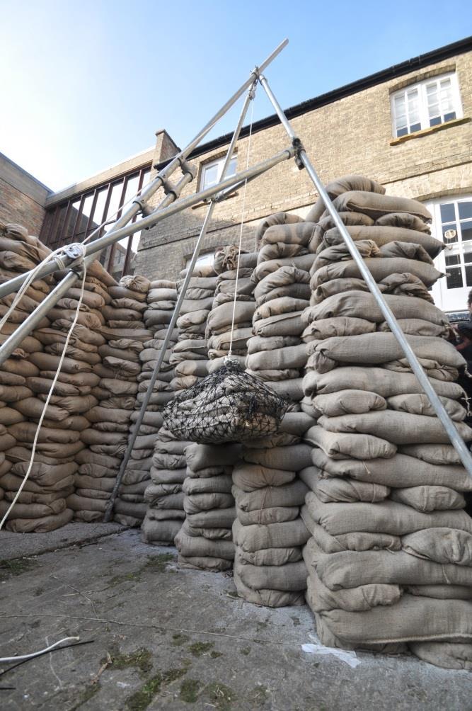
5 Static load test location unreinforced pier Dynamic load test location unreinforced Static load test location reinforced pier Accelerometer locations Static load tests: Involved testing an unreinforced wall end/pier. Horizontal loads were applied incrementally, increasing in magnitude to 120kg at 135cm above ground level. Between load increments the wall was allowed to recover to enable recording of any plastic deflection. Deflections were recorded. No failures occurred. Dynamic load tests: Involved a 50kg pendulum test to an end wall panel. The test was designed to follow BS EN 12600:2002 as close as possible. Pendulum heights of 65cm and 115cm above ground level were investigated. Pendulum back swings varied from 40cm to 200cm from the face of the wall. Deflections and accelerations were recorded. No failures occurred. Abuse load tests: 3no. students scaled the wall simultaneously and stood on the wall. Push-over tests: Both wall ends/piers were pushed over, one unreinforced and one pre-stressed (approximately 85kg) with strapping. Loads were applied 135cm above ground level and recorded at failure. Each hessian sandbag was filled with typically 24kg of building sand and when placed in the wall formed a brick of typically 600x300x90mm. Photos from the test panel build process can be seen in appendix B. SaW_Venice Biennale_Sandbag Wall Load Testing_March 2013 Page 5
6 Results from Sandbag Wall Testing Data from the load testing can be found in appendix D and photos of the load testing can be seen in appendix C. During both the static and dynamic testing the sandbag wall remained stable albeit with some permanent deflection recorded during both tests. Failures were only encountered in the push-over tests. Static load test on unreinforced pier: An elastic deflection of 38mm (measured at 175cm above ground) under a 1.2kN load (applied at 135cm above ground) was recorded. On release of the load recovery was 30mm giving a permanent deflection of 8mm. As can be seen from the plot of the deflections against load below the relationship begins linear moving to exponential at the 1kN load stage. 40 Static Load Test - Unreinforced Pier Elastic deflection (175cm) Plastic deflection (175cm) Elastic deflection (121cm) Plastic deflection (121cm) Trend line (175cm) Trend Line (121cm) Push-over test to unreinforced pier: The pier failed at 2kN load applied 135cm above ground. As can be seen from the photos in appendix C the pier failed approximately 80cm above ground accompanied by a partial collapse of the adjoining wall panel. Push-over test to reinforced pier: The pier failed at 3kN load applied 135cm above ground. As can be seen from the photos in appendix C the pier failed approximately 60cm above ground accompanied by a partial collapse of the adjoining wall panel (albeit not as much as with the unreinforced pier). The pre-stressing strap failed in tension at the point of push-over. The failure occurred at a point of damage to the strap. SaW_Venice Biennale_Sandbag Wall Load Testing_March 2013 Page 6
7 Dynamic load test to unreinforced wall panel: In both pendulum tests the deflections measured, both elastic and plastic, were negligible (less than 5mm). The accelerations experienced by the wall ranged from zero up to 0.7g and can be seen in the graphs below. The sampling rate was 0.1sec cm High Pendulum Wall Accelerations End of wall accelerations Central wall accelerations The duration of the test was 5 minutes and 30 seconds and the lag shown between each location represents approximately 8 seconds cm High Pendulum Wall Accelerations End of wall accelerations Central wall accelerations The duration of the test was 5 minutes and 30 seconds and the lag shown between each location represents approximately 8 seconds. SaW_Venice Biennale_Sandbag Wall Load Testing_March 2013 Page 7

8 Other: During the tests it was possible to observe a potential weakness in the wall. At the pier locations the bond pattern introduced a clear vertical joint that ran the full height of the wall for half its depth. Under horizontal loading this joint was seen to open up. The robustness of the wall could be increased if the wall was reinforced here, either through a revised bond pattern or barbed wire reinforcement. Image highlights points at which joint opening-up was observed under load testing Discussion of Test Results The load testing provided considerable data from which it is possible to gain a fuller understanding of the way in which the sandbag wall responds to various load conditions. The discussions here are limited to the wall ends or piers as the central sections of the sandbag wall were observed to be extremely robust and not thought to require any further discussion. Unreinforced pier (static load and push-over test results): From both the static load test and push-over test it is clear that the pier does not exhibit full rigid body behaviour (at higher loads) and that its strength is influenced by the adjoining wall panel. This is evident from non-linear deflection behaviour, the failure at 800mm above ground and the wedge shape failure of the adjacent wall panel (see photos in appendix C). Furthermore the theoretical push-over moment of a 0.6x0.6x2m tall sandbag pier with a mass of 1100kg (ie 46no. 24kg sandbags) acting as a rigid body is 3.3kNm. This represents a push-over load of 2.5kN which is 25% higher than the 2kN experienced in the test. SaW_Venice Biennale_Sandbag Wall Load Testing_March 2013 Page 8
9 Deflection (mm) Using the static load deflection curves it is possible to predict the failure of the unreinforced pier as can be seen in the graph below. Assuming a tipping point of 300mm horizontal deflection at pier mig-height (ie when the centre of mass of the pier rotates outside of the pier footprint) the predicted force to achieve push-over is 195kg applied at 135cm above ground. This can be compared to the 200kg load observed in the test. The extrapolation of the load deflection lines was undertaken in MS Excel using 3 rd order polynomial functions Prediction of failure load of unreinforced pier deflection at 175cm deflection at 121cm Load (kg) The failure of the unreinforced pier at 2kN is not acceptable when considering the regulation loads and the deflections experienced at this magnitude of load. For crowd loading regulations will require up to 3kN/m applied at 1.1m above ground (equivalent to stadia balustrade loading) which on a 0.6m wide pier equates to 1.8kN. Crowd loading has been used due to the potential for increased pedestrian traffic at points of entry and exit. According to the tests carried out this would give a factor of safety of 1.35 for the unreinforced pier which is not acceptable and a factor of safety of at least 2.0 will be required by the authorities. By extending the wall height to 2.5m (as per the project proposals) the push-over load is increased to 2.5kN and factor of safety to 1.7 although this is a slight simplification of what would happen in reality. Reinforced pier (push-over test results): From push-over test it is clear that the reinforced pier is tending to rigid body behaviour and that its strength is only slightly influenced by the adjoining wall panel. This is evident from the failure being SaW_Venice Biennale_Sandbag Wall Load Testing_March 2013 Page 9
10 lower down at 600mm above ground and the failure of the adjacent wall panel being limited to only a few sandbags (see photos in appendix C). The failure of the pre-stress strap during the push-over test indicates that the pre-stress load increased during the deformation of the pier. The final pre-stress design solution should take this in to consideration. The reinforced pier failed above the theoretical push-over load of 2.5kN. With a failure load of 3kN the factor of safety against push-over is 2.0 which is adequate. By extending the wall height to 2.5m (as per the project proposals) in the push-over load is increased to 3.75kN and factor of safety to 2.5 although this is a slight simplification of what would happen in reality. Dynamic load test to unreinforced wall panel: The wall performed extremely robustly during the pendulum tests. Both elastic and plastic deflections were negligible and dissipation of the impact energy in the wall was excellent, as can be seen by back analysis of the estimated force exerted during the maximum pendulum swing. These forces are estimated to be 10kN (115cm height) and 15kN (65cm height) and when viewed against the deflections experienced and compared to the static load tests results the sandbag wall energy adsorption properties are significant. The dynamic load test also reinforced our empirical observations that the central portion of the sawtooth profile wall was highly stable as an unreinforced sandbag structure. Again the difference in magnitude of the accelerations measured at the two points in the test panel (typically a factor 5 to 10 difference) provides measured evidence of this. Structural Design Recommendations The following recommendations are made in order to achieve a structurally stable sandbag wall installation to the saw-tooth wall profile: 1. The saw-tooth end walls should be designed to crowd horizontal loading of 3kN/m at 1.1m above floor level. 2. The saw-tooth wall profile requires pier reinforcement at opening points, ie at wall ends. This will provide adequate stability against push-over for a wall height of 2m or 2.5m. 3. The reinforcement could be formed in a number of ways. If pre-stressing is adopted then a minimum pre-stress force of 0.85kN is required. 4. The pre-stress force may dissipate over time and therefore a detail should be developed that maintains a constant force (ie spring head) or a detail that is adjusted on a regular basis. 5. The baseplate to the reinforcement would benefit from extending it under the sandbag floor and/or adjacent wall sandbags. 6. The joint opening up observed during load tests should be eliminated through revising the bond pattern or introducing local barbed wired bed joint reinforcement. SaW_Venice Biennale_Sandbag Wall Load Testing_March 2013 Page 10
11 The following recommendations are made in order to achieve a structurally stable sandbag wall installation to the flat end walls: 7. The flat end walls should be designed to horizontal loading of 1.5kN/m at 1.1m above floor level. 8. The flat end walls require reinforcement at 1.2m centres throughout their length. This will provide adequate stability against push-over for a wall height of 2m or 2.5m. 9. The reinforcement could be formed in a number of ways. If pre-stressing is adopted then a minimum pre-stress force of 0.85kN is required. 10. The pre-stress force may dissipate over time and therefore a detail should be developed that maintains a constant force (ie spring head) or a detail that is adjusted on a regular basis. 11. The baseplate to the reinforcement would benefit from extending it under the sandbag floor. Details of the proposed sandbag wall reinforcement can be seen in appendix A. Roz Barr Architects will specify the construction details to ensure that this detail is applied during the construction process. The insertion of the pre-stress detail within each end of wall pier section will offer greater stability of the structure and the 2.5m wall. The stability of all sandbag walls built will also rely on a well-constructed installation. The tolerances achieved during construction should be closely monitored so that vertically plumb walls are achieved. Closely controlling the sandbag filling process so that each bag is filled with the same amount of sand is essential. The test panel build process has indicated that for the bags used, the ideal fill weight of sand is around 24kg to 25kg. SaW_Venice Biennale_Sandbag Wall Load Testing_March 2013 Page 11
12 Appendices Appendix A Engineering sketches Appendix B Photos from Test Panel Build Process Appendix C Photos from Test Panel Load Testing Appendix D Results from Test Panel Load Testing SaW_Venice Biennale_Sandbag Wall Load Testing_March 2013 Page 12
13 Appendix A Engineering Sketches Sketch showing sandbag wall reinforcement proposals SaW_Venice Biennale_Sandbag Wall Load Testing_March 2013 Page 13
14 Appendix A Engineering Sketches Sketch showing early thoughts SaW_Venice Biennale_Sandbag Wall Load Testing_March 2013 Page 14


15 Appendix B Photos from test panel build process SaW_Venice Biennale_Sandbag Wall Load Testing_March 2013 Page 15


16 Appendix C Photos from test panel load testing SaW_Venice Biennale_Sandbag Wall Load Testing_March 2013 Page 16


17 Appendix C Photos from test panel load testing SaW_Venice Biennale_Sandbag Wall Load Testing_March 2013 Page 17


18 Appendix C Photos from test panel load testing SaW_Venice Biennale_Sandbag Wall Load Testing_March 2013 Page 18
19 Appendix D Results from test panel load testing SaW_Venice Biennale_Sandbag Wall Load Testing_March 2013 Page 19
20 Appendix D Results from test panel load testing SaW_Venice Biennale_Sandbag Wall Load Testing_March 2013 Page 20
All- Glass Staircase, Notting Hill, London
 All- Glass Staircase, Notting Hill, London Wilfried Laufs, Werner Sobek Ingenieure, Stuttgart, Germany To bring direct day- light into a domestic housing staircase area in London, an all- glass staircase
Base isolation. Philippe Bisch IOSIS, EGIS group. EUROCODE 8 Background and Applications
 EUROCODE 8 Background and Applications Dissemination of information for training Lisbon, 10-11 February 2011 1 Base isolation Philippe Bisch IOSIS, EGIS group EUROCODE 8 Background and Applications BASE
Seismic Damage-Resistant System for Multi-Storey Modular Light Steel Framed Buildings
 Seismic Damage-Resistant System for Multi-Storey Modular Light Steel Framed Buildings John Jing 1 and G. Charles Clifton 2 1. Structural Engineer, BSc., BE Civil (Hons.) and PhD (Civil), Harrison Grierson
Level 6 Graduate Diploma in Engineering Structural analysis
 9210-111 Level 6 Graduate Diploma in Engineering Structural analysis Sample Paper You should have the following for this examination one answer book non-programmable calculator pen, pencil, ruler, drawing
Seismic Rehabilitation of Selby Condominium Complex, Montreal (Quebec), Canada
, Canada") Seismic Rehabilitation of Selby Condominium Complex, Montreal (Quebec), Canada M. Zarrabi & R. Bartosh BCA Consultants, Montreal, Quebec, Canada A. Pall Pall Dynamics Limited, Montreal, Canada SUMMARY
Seismic Rehabilitation of Selby Condominium Complex, Montreal (Quebec), Canada M. Zarrabi & R. Bartosh BCA Consultants, Montreal, Quebec, Canada A. Pall Pall Dynamics Limited, Montreal, Canada SUMMARY
Unit 48: Structural Behaviour and Detailing for Construction. Limit State Design
 2.1 Introduction Limit State Design Limit state design of an engineering structure must ensure that (1) under the worst loadings the structure is safe, and (2) during normal working conditions the deformation
Client Report : A design method for use with 6mm diameter Thor Helical twistfix wires used as retrofitted bedjoint reinforcement
 Client Report : A design method for use with 6mm diameter Thor Helical twistfix wires used as retrofitted bedjoint reinforcement Client report number 214151 Prepared for : Dave Chadwick 19 th November
EARTHQUAKE RESPONSE ANALYSIS OF MID-STORY BUILDINGS ISOLATED WITH VARIOUS SEISMIC ISOLATION TECHNIQUES
 EARTHQUAKE RESPONSE ANALYSIS OF MID-STORY BUILDINGS ISOLATED WITH VARIOUS SEISMIC ISOLATION TECHNIQUES N. Torunbalci 1 and G. Ozpalanlar 2 1 Assoc. Professor Dr., Dept. of Structural Engineering, Faculty
Pushover Analysis Of RCC Building With Soft Storey At Different Levels.
 Pushover Analysis Of RCC Building With Soft Storey At Different Levels. Achyut S. Naphade 1, Prof. G. R. Patil 2 1 (M.E. (Structure) Student, Department of Civil Engineering Rajarshi Shahu College of Engineering,
PERFORMANCE STUDY OF RETROFITTED GRAVITY LOAD DESIGNED WALL FRAME STRUCTURES (SC-140)
") PERFORMANCE STUDY OF RETROFITTED GRAVITY LOAD DESIGNED WALL FRAME STRUCTURES (SC-140) *A. Ahmed 1, K. H. Tan 1 1 Department of Civil and Environmental Engineering National University of Singapore, Singapore,
PERFORMANCE STUDY OF RETROFITTED GRAVITY LOAD DESIGNED WALL FRAME STRUCTURES (SC-140) *A. Ahmed 1, K. H. Tan 1 1 Department of Civil and Environmental Engineering National University of Singapore, Singapore,
Chapter. Masonry Design
 Chapter Masonry Design The masonry design section contains modules for the analysis of reinforced masonry beams subjected to pure bending and unreinforced masonry walls subjected to axial compression and
Assistant Professor, Applied Mechanics Department, Government College of Engineering, Amravati, India 2
 [Akhare et al., 3(5): May, 1] ISSN: 77-955 Scientific Journal Impact Factor: 3.9 (ISRA), Impact Factor: 1.5 IJESRT INTERNATIONAL JOURNAL OF ENGINEERING SCIENCES & RESEARCH TECHNOLOGY Seismic Performance
CHAPTER 5 FINITE ELEMENT MODELING
 CHAPTER 5 FINITE ELEMENT MODELING 5.1 INTRODUCTION Masonry is a composite material with the building brick units and the mortar as the joining material, which are bonded together. Guinea [2000] 51 reported
AN ANALYSIS OF MEMBRANE ACTION IN ONE-WAY CONCRETE MEMBERS EXTERNALLY BONDED WITH FRP
 The 12th International Symposium on Fiber Reinforced Polymers for Reinforced Concrete Structures (FRPRCS-12) & The 5th Asia-Pacific Conference on Fiber Reinforced Polymers in Structures (APFIS-2015) Joint
S. Gandhi *1, Syed Rizwan 2
 2017 IJSRSET Volume 3 Issue 3 Print ISSN: 2395-1990 Online ISSN : 2394-4099 Themed Section: Engineering and Technology Analysis and Design of Tall Building (G+21) Using ETABS S. Gandhi *1, Syed Rizwan
NON-LINEAR STATIC PUSHOVER ANALYSIS FOR MULTI-STORED BUILDING BY USING ETABS
 NON-LINEAR STATIC PUSHOVER ANALYSIS FOR MULTI-STORED BUILDING BY USING ETABS Polupalli Victor Paul 1, K Sampath Kumar 2 1 PG Student, Dept of Civil Engineering, Nova College of Engineering & Technology,
Modelling of Long-Term Loading Tests on Reinforced Concrete Beams N. Reybrouck; P. Criel; R. Caspeele; and L. Taerwe
 CONCREEP 10 745 Modelling of Long-Term Loading Tests on Reinforced Concrete Beams N. Reybrouck; P. Criel; R. Caspeele; and L. Taerwe Magnel Laboratory for Concrete Research, Department of Structural Engineering,
EXPERIMENTAL INVESTIGATION ON NON-ENGINEERED MASONRY HOUSES IN LOW TO MODERATE SEISMICITY AREAS
 The 4 th World Conference on Earthquake Engineering October 2-7, 28, Beijing, China EXPERIMENTAL INVESTIGATION ON NON-ENGINEERED MASONRY HOUSES IN LOW TO MODERATE SEISMICITY AREAS ABSTRACT : H. Degée,
The concept of statical determinacy
 Appendix 3 The concept of statical determinacy 140 A3.1 Introduction It has been shown that the conditions for equilibrium of a set of coplanar forces can be summarised in the three equations of equilibrium
ESECMASE - SHEAR TEST METHOD FOR MASONRY WALLS WITH REALISTIC BOUNDARY CONDITIONS
 ESECMASE - SHEAR TEST METHOD FOR MASONRY WALLS WITH REALISTIC BOUNDARY CONDITIONS E. FEHLING Professor of Civil Engineering Institute of Structural Engineering Chair of Structural Concrete University of
Modelling of post-tensioned precast reinforced concrete frame structures with rocking beam-column connections
 Modelling of post-tensioned precast reinforced concrete frame structures with rocking beam-column connections H.A. Spieth, A.J. Carr, A.G. Murahidy, D. Arnolds, M. Davies, J.B. Mander University of Canterbury,
BOUNDARY CONDITIONS OF SHEAR WALLS IN MULTI-STOREY MASONRY STRUCTURES UNDER HORIZONTAL LOADINGS
 BOUNDARY CONDITIONS OF SHEAR WALLS IN MULTI-STOREY MASONRY STRUCTURES UNDER HORIZONTAL LOADINGS K. ZILCH Professor, Institute of Building Materials and Structures Chair of Concrete Structures Technische
Blast resistant design and limits of the response of a structure to an external explosion
 Structures Under Shock and Impact XII 229 Blast resistant design and limits of the response of a structure to an external explosion D. Makovička 1 & D. Makovička Jr 2 1 Czech Technical University in Prague,
PRELIMINARY FINITE ELEMENT ANALYSIS OF A MASONRY ARCH BRIDGE WITH NEAR-SURFACE REINFORCEMENT. Stephen.W.Garrity 1 and Irina L.
 PRELIMINARY FINITE ELEMENT ANALYSIS OF A MASONRY ARCH BRIDGE WITH NEAR-SURFACE REINFORCEMENT Stephen.W.Garrity 1 and Irina L.Toropova 1 ABSTRACT A three-dimensional finite element analysis of a typical
A new approach for the Seismic Isolation Methods for Ancient Statues Displayed in Base Isolated Museums
 A new approach for the Seismic Isolation Methods for Ancient Statues Displayed in Base Isolated Museums C.A Castiglioni, A. Kanyilmaz Politecnico di Milano, Italy SUMMARY: In order to protect the precious
General Structural Concerns
 1/28 General Structural Concerns Functionality / Stiffness deformations Stability equilibrium Strength material behaviour 2/28 Stability Loads act on structure tend to destabilise structure also tend to
PREDICTION OF SEISMIC TORSIONAL EFFECTS IN TALL SYMMETRIC BUILDINGS
 PREDICTION OF SEISMIC TORSIONAL EFFECTS IN TALL SYMMETRIC BUILDINGS C. Justine Jose, T. P. Somasundaran & V. Mustafa Civil Engineering Department, National Institute of Technology Calicut, Kozhikode, Kerala-673601,
0306 SEISMIC LOADS GENERAL
 0306 SEISMIC LOADS 0306.1 GENERAL Every structure, and portion thereof, including nonstructural components such as architectural, mechanical, and electrical components, shall be designed and constructed
CHAPTER III DYNAMIC BEHAVIOR OF A LABORATORY SPECIMEN
 CHAPTER III DYNAMIC BEHAVIOR OF A LABORATORY SPECIMEN To address the vibration response of a long span deck floor system, an experiment using a specimen that resembles the conditions found in the in-situ
COMPARISON OF A REINFORCED CONCRETE BUILDING STRENGTHRND WITH VARIOUS METHODS
 COMPARISON OF A REINFORCED CONCRETE BUILDING STRENGTHRND WITH VARIOUS METHODS Farnaz ALINOORI 1 and Kadir GÜLER 2 ABSTRACT The earthquake performance of a school building having three stories which has
To have a clear idea about what really happened and to prevent the
 Failure Analysis on Skunk-Arm of Electrical Tower Failure Analysis on Skunk-Arm of Electrical Tower ABSTRACT Ahmad Rivai 1, Md Radzai Said 2 1, 2 Faculty of Mechanical Engineering, Universiti Teknikal
Fig [1] clamp metal wire BENCH TOP. Fig. 7.2
![Fig [1] clamp metal wire BENCH TOP. Fig. 7.2](/thumbs/81/82881722.jpg "Fig [1] clamp metal wire BENCH TOP. Fig. 7.2") 1 (a) Fig. 7.1 shows a length of tape under tension. pull B pull Fig. 7.1 (i) Explain why the tape is most likely to break at point B.... [1] (ii) Explain what is meant by the statement: the tape has gone
1 (a) Fig. 7.1 shows a length of tape under tension. pull B pull Fig. 7.1 (i) Explain why the tape is most likely to break at point B.... [1] (ii) Explain what is meant by the statement: the tape has gone
Earthquake Design of Flexible Soil Retaining Structures
 Earthquake Design of Flexible Soil Retaining Structures J.H. Wood John Wood Consulting, Lower Hutt 207 NZSEE Conference ABSTRACT: Many soil retaining wall structures are restrained from outward sliding
SEISMIC DESIGN OF STRUCTURE
 SEISMIC DESIGN OF STRUCTURE PART I TERMINOLOGY EXPLANATION Chapter 1 Earthquake Faults Epicenter Focal Depth Focus Focal Distance Epicenter Distance Tectonic Earthquake Volcanic Earthquake Collapse Earthquake
BRACED FRAME USING ASYMMETRICAL FRICTION CONNECTIONS (AFC)
") 8 th International Conference on Behaviour of Steel Structures in Seismic Areas Shanghai, China, July 1-3, 2015 BRACED FRAME USING ASYMMETRICAL FRICTION CONNECTIONS (AFC) J. Chanchi Golondrino*, R. Xie,
8 th International Conference on Behaviour of Steel Structures in Seismic Areas Shanghai, China, July 1-3, 2015 BRACED FRAME USING ASYMMETRICAL FRICTION CONNECTIONS (AFC) J. Chanchi Golondrino*, R. Xie,
Beam-column joint tests with grade 500E reinforcing
 Beam-column joint tests with grade 500E reinforcing L.M. Megget & N.J. Brooke Department of Civil & Environmental Engineering, University of Auckland, New Zealand. R.C. Fenwick Visitor, Department of Civil
International Journal of Scientific & Engineering Research, Volume 7, Issue 10, October ISSN Pushover Analysis of RC Building
 International Journal of Scientific & Engineering Research, Volume 7, Issue 10, October-2016 88 Pushover Analysis of RC Building Dona Mary Daniel, Shemin T. John Abstract In this study the seismic response
COMPARATIVE ANALYSIS OF SEISMIC ISOLATED SYSTEMS IN BRIDGES
 COMPARATIVE ANALYSIS OF SEISMIC ISOLATED SYSTEMS IN BRIDGES APPLICATION TO A STUDY CASE João Tiago Ferreira Marques de Abreu Abstract This paper represents the resume of a study where is evaluated the
BEHAVIOUR OF REINFORCED CONCRETE STRUCTURES IN FIRE
 BEHAVIOUR OF REINFORCED CONCRETE STRUCTURES IN FIRE ZHAOHUI HUANG, IAN W. BURGESS and ROGER J. PLANK 3 ABSTRACT In the past two decades, a significant amount of research has been conducted into the performance
Rail Track Analysis Wizard
 Rail Track Analysis Wizard M I D A S I T 111-1 01 Rail Track Analysis Wizard The Rail Track Analysis Wizard builds a model that is used for checking the additional stresses and the displacements due to
Figure 1: Construction of arch unit using pre-cast individual voussoir concrete blocks (Taylor et al, 2007)
") CONSTRUCTION OF TIEVENAMEENA BRIDGE USING A FLEXI-ARCH SYSTEM A.GUPTA 2, S.E.TAYLOR 1, J KIRKPATRICK 2, AE LONG 1 and I HOGG 2, 1 School of Planning, Architecture and Civil Engineering, Queen s University
CONSTRUCTION OF TIEVENAMEENA BRIDGE USING A FLEXI-ARCH SYSTEM A.GUPTA 2, S.E.TAYLOR 1, J KIRKPATRICK 2, AE LONG 1 and I HOGG 2, 1 School of Planning, Architecture and Civil Engineering, Queen s University
EXPERIMENTAL STUDY REGARDING THE BEHAVIOR OF GLUE LAMINATED BEAMS DOUBLE REINFORCED WITH RECTANGULAR METAL PIPES (RMP)
") Bulletin of the Transilvania University of Braşov CIBv 2014 Vol. 7 (56) Special Issue No. 1-2014 EXPERIMENTAL STUDY REGARDING THE BEHAVIOR OF GLUE LAMINATED BEAMS DOUBLE REINFORCED WITH RECTANGULAR METAL
Bulletin of the Transilvania University of Braşov CIBv 2014 Vol. 7 (56) Special Issue No. 1-2014 EXPERIMENTAL STUDY REGARDING THE BEHAVIOR OF GLUE LAMINATED BEAMS DOUBLE REINFORCED WITH RECTANGULAR METAL
GEO-SLOPE International Ltd, Calgary, Alberta, Canada Tie-back Wall
 1 Introduction Tie-back Wall This example simulates the sequential construction of a sheet-pile shoring wall tied back with pre-stressed anchors. The purpose is to demonstrate the steps involved in modeling
THE BEHAVIOUR OF LIGHTWEIGHT COMPOSITE FLOOR TRUSSES IN FIRE
 THE BEHAVIOUR OF LIGHTWEIGHT COMPOSITE FLOOR TRUSSES IN FIRE S.K. Choi, I.W. Burgess Department of Civil and Structural Engineering, University of Sheffield, Sheffield S1 3JD, UK R.J. Plank School of Architecture,
Structural Performance of 8-inch NRG Concrete Masonry Units. Report Compiled for: Niagara Regional Group. Date: January 28, 2013
 Structural Performance of 8-inch NRG Concrete Masonry Units Report Compiled for: Niagara Regional Group Date: January 28, 2013 Report Prepared by: Dr. Shawn Gross, Associate Professor Dr. David Dinehart,
Seismic Evaluation of the Historic East-Memorial Building Retrofitted with Friction Dampers, Ottawa, Canada
 Seismic Evaluation of the Historic East-Memorial Building Retrofitted with Friction Dampers, Ottawa, Canada S. Jabbour & D.J. Carson Parsons Brinckerhoff Halsall Inc. SUMMARY: A seismic evaluation under
EVALUATION OF THE NEED FOR WEAK BEAM-STRONG COLUMN DESIGN IN DUAL FRAME-WALL STRUCTURES
 EVALUATION OF THE NEED FOR WEAK BEAM-STRONG COLUMN DESIGN IN DUAL FRAME-WALL STRUCTURES Rita BENTO And Mário LOPES SUMMARY According to Capacity Design principles, in multi-storey frames it is considered
Comparison of Sway Analysis of RC Frames using Cracked Moment of Inertia
 Comparison of Sway Analysis of RC Frames using Cracked Moment of Inertia M. Sabbir U. Chowdhury 1 and Tahsin Reza Hossain Abstract Sway of reinforced concrete (RC) frames subjected to lateral load is an
CONSIDERATIONS ON THE SLIP DEMAND OF SHEAR CONNECTORS IN COMPOSITE STEEL-CONCRETE BEAMS WITH SOLID SLABS
 CONSIDERATIONS ON THE SLIP DEMAND OF SHEAR CONNECTORS IN COMPOSITE STEEL-CONCRETE BEAMS WITH SOLID SLABS A. Zona 1 and G. Ranzi, * 1 School of Architecture and Design, University of Camerino, Ascoli Piceno,
SIMPLE INVESTIGATIONS OF TENSILE MEMBRANE ACTION IN COMPOSITE SLABS IN FIRE
 SIMPLE INVESTIGATIONS OF TENSILE MEMBRANE ACTION IN COMPOSITE SLABS IN FIRE By Ahmed Allam 1, Ian Burgess 1 and Roger Plank 1 Department of Civil and Structural Engineering, University of Sheffield, UK
Effect of Diaphragm Openings in Multi-storeyed RC framed buildings using Pushover analysis
 Effect of Diaphragm Openings in Multi-storeyed RC framed buildings using Pushover analysis P.P. Vinod Kumar 1, Dr. V.D. Gundakalle 2 1 M.Tech Student, Civil Engineering, KLEMSSCET - Belagavi, Karnataka,
Analysis of Reinforced Concrete. Workshop Prague, March 30-31, 31, 2007 COST Action C26
 Analysis of Reinforced Concrete Structures Subjected to Blast Loading S. Karapinar,, I. Sanri,, G. Altay Workshop Prague, March 30-31, 31, 2007 COST Action C26 Aim of the Study Analyze the structures under
The need to design for robustness in fire. Ian Burgess
 The need to design for robustness in fire Ian Burgess Robustness a working definition The ability of a structure to avoid disproportionate collapse when subject to a localised failure Hence: Only structural
International Journal of Intellectual Advancements and Research in Engineering Computations
 www.ijiarec.com ISSN:2348-2079 Volume-5 Issue-1 International Journal of Intellectual Advancements and Research in Engineering Computations Pushover analysis on rc frames with and without shear wall Parishith
Masonry Wall Bracing. A Simplified Approach To Bracing Masonry Walls Under Construction. Masonry Bracing Task Force.
 Masonry Wall Bracing A Simplified Approach To Bracing Masonry Walls Under Construction Produced by the Masonry Wall Bracing A Simplified Approach to Bracing Masonry Walls Under Construction Produced by
SEISMIC STRENGTHENING AND REPAIR OF REINFORCED CONCRETE SHEAR WALLS
 SEISMIC STRENGTHENING AND REPAIR OF REINFORCED CONCRETE SHEAR WALLS Josh LOMBARD 1, David T LAU 2, Jag L HUMAR 3, Simon FOO 4 And M S CHEUNG 5 SUMMARY This paper presents the results obtained in a feasibility
Performance based Displacement Limits for Reinforced Concrete Columns under Flexure
 Performance based Displacement Limits for Reinforced Concrete Columns under Flexure Ahmet Yakut, Taylan Solmaz Earthquake Engineering Research Center, Middle East Technical University, Ankara,Turkey SUMMARY:
THE PERFORMANCE OF CONCRETE GROUND FLOOR SLAB REINFORCEMENT TO CONTROL SHRINKAGE CRACKING. D H Chisholm 1
 THE PERFORMANCE OF CONCRETE GROUND FLOOR SLAB REINFORCEMENT TO CONTROL SHRINKAGE CRACKING D H Chisholm 1 ABSTRACT In a typical residential concrete floor slab, the cast in strip footings on the slab perimeter
Page 1 of 46 Exam 1. Exam 1 Past Exam Problems without Solutions NAME: Given Formulae: Law of Cosines: C. Law of Sines:
 NAME: EXAM 1 PAST PROBLEMS WITHOUT SOLUTIONS 100 points Tuesday, September 26, 2017, 7pm to 9:30 You are allowed to use a calculator and drawing equipment, only. Formulae provided 2.5 hour time limit This
A Study into the Earthquake Resistance of Circular Adobe Buildings using Static Tilt Tests
 Australian Earthquake Engineering Society 2010 Conference, Perth, Western Australia A Study into the Earthquake Resistance of Circular Adobe Buildings using Static Tilt Tests W. Jinwuth 1, B. Samali 2,
Design of a Beam Structure for Failure Prevention at Critical Loading Conditions
 International Academic Institute for Science and Technology International Academic Journal of Innovative Research Vol. 3, No. 10, 2016, pp. 32-44. ISSN 2454-390X International Academic Journal of Innovative
Using friction dampers for improving earthquake response of self-variable stiffness RC framed buildings
 Using friction dampers for improving earthquake response of self-variable stiffness RC framed buildings I. Iskhakov & Y. Ribakov Department of Civil Engineering, Ariel University Center of Samaria, Israel
INFLUENCE OF BNWF SOIL MODELLING ON DYNAMIC BEHAVIOUR OF PILE FOUNDATION FOR RC FRAME WITH STRUCTURAL WALL
 ICOVP, 3 th International Conference on Vibration Problems 29 th November 2 nd December, 27, Indian Institute of Technology Guwahati, INDIA INFLUENCE OF BNWF SOIL MODELLING ON DYNAMIC BEHAVIOUR OF PILE
GEO-SLOPE International Ltd, Calgary, Alberta, Canada Tie-back Wall
 1 Introduction Tie-back Wall This example simulates the sequential construction of a sheet-pile shoring wall tied back with pre-stressed anchors. The purpose is to demonstrate the steps involved in modeling
Analysis of Buried Arch Structures; Performance Versus Prediction
 Analysis of Buried Arch Structures; Performance Versus Prediction D.A. Jenkins: Reinforced Earth Pty Ltd, Somersby, NSW, Australia Synopsis: The Reinforced Earth Group introduced the TechSpan arch system
Abstract. 1 Introduction
 Ultimate deformation capacity of reinforced concrete slabs under blast load J.C.A.M. van Doormaal, J. Weeheijm TNO PrinsMaurits Laboratory, P.O. Box 45, 2280 AA Rijswijk, The Netherlands Abstract In this
Non-Linear Pushover Analysis of Flatslab Building by using Sap2000
 ANALELE UNIVERSITĂłII EFTIMIE MURGU REŞIłA ANUL XIX, NR. 1, 2012, ISSN 1453-7397 K. Soni Priya, T. Durgabhavani, K. Mounika, M. Nageswari, P. Poluraju Non-Linear Pushover Analysis of Flatslab Building
Displacement Based Assessment and Improvement of a Typical New Zealand Building by an Average Engineer
 Displacement Based Assessment and Improvement of a Typical New Zealand Building by an Average Engineer M.L. Grant LGE Consulting, Masterton 2016 NZSEE Conference ABSTRACT: The Radiohouse building is a
AN EXAMINATION OF DAMAGES OF REINFORCED CONCRETE CONSOLED BUILDINGS IN TURKEY DUE TO 17 AUGUST 1999 KOCAELI EARTHQUAKE
 13th World Conference on Earthquake Engineering Vancouver, B.C., Canada August 1-6, 2004 Paper No. 2644 AN EXAMINATION OF DAMAGES OF REINFORCED CONCRETE CONSOLED BUILDINGS IN TURKEY DUE TO 17 AUGUST 1999
Seismic Performance of Multistorey Building with Soft Storey at Different Level with RC Shear Wall
 Research Article International Journal of Current Engineering and Technology E-ISSN 2277 4106, P-ISSN 2347-5161 2014 INPRESSCO, All Rights Reserved Available at http://inpressco.com/category/ijcet Seismic
NEW COMPOSITE CONSTRUCTION OF HYBRID BEAMS COMBINING STEEL INVERTED T-SECTION AND RC FLANGE
 NEW COMPOSITE CONSTRUCTION OF HYBRID BEAMS COMBINING STEEL INVERTED T-SECTION AND RC FLANGE Alex Remennikov 1, Marcus Roche 2 ABSTRACT: Steel and concrete composite beams are typically formed by shear
Vertical Incremental Dynamic Analysis for Assessing Progressive Collapse Resistance and Failure Modes of Structures
 The 4th International Workshop on Reliable Engineering Computing (REC 2010) Vertical Incremental Dynamic Analysis for Assessing Progressive Collapse Resistance and Failure Modes of Structures Dagang Lu,
Introduction to Structural Analysis TYPES OF STRUCTURES LOADS AND
 AND Introduction to Structural Analysis TYPES OF STRUCTURES LOADS INTRODUCTION What is the role of structural analysis in structural engineering projects? Structural engineering is the science and art
UNIVERSITY OF BOLTON SCHOOL OF ENGINEERING. BEng (Hons) CIVIL ENGINEERING
 CIVIL ENGINEERING") TW7 UNIVERSITY OF BOLTON SCHOOL OF ENGINEERING BEng (Hons) CIVIL ENGINEERING SEMESTER 2 EXAMINATION 2015/2016 ADVANCED STRUCTURAL ANALYSIS & DESIGN MODULE NO. CIE6001 Date: Thursday 19 th May 2016 Time:
TW7 UNIVERSITY OF BOLTON SCHOOL OF ENGINEERING BEng (Hons) CIVIL ENGINEERING SEMESTER 2 EXAMINATION 2015/2016 ADVANCED STRUCTURAL ANALYSIS & DESIGN MODULE NO. CIE6001 Date: Thursday 19 th May 2016 Time:
A Comparative Study on Non-Linear Analysis of Frame with and without Structural Wall System
 A Comparative Study on Non-Linear Analysis of Frame with and without Structural Wall System Dr.Binu Sukumar #1, A.Hemamathi *2, S.Kokila #3 C.Hanish #4 #1 Professor &Head, Department of Civil Engineering,
Typical set up for Plate Load test assembly
 Major disadvantages of field tests are Laborious Time consuming Heavy equipment to be carried to field Short duration behavior Plate Load Test Sand Bags Platform for loading Dial Gauge Testing Plate Foundation
Improving the Seismic Response of a Reinforced Concrete Building Using Buckling Restrained Braces
 Bauhaus Summer School in Forecast Engineering: From Past Design to Future Decision 22 August 2 September 2016, Weimar, Germany Improving the Seismic Response of a Reinforced Concrete Building Using Buckling
Outline of Presentation. Behavior of Laterally Loaded Piles in A Mechanically Stabilized Earth (MSE) Wall
 Wall") Behavior of Laterally Loaded Piles in A Mechanically Stabilized Earth (MSE) Wall Jie Han, Ph.D., PE, F.ASCE Glenn L. Parker Professor of Geotechnical Engineering The University of Kansas, USA Outline of
Behavior of Laterally Loaded Piles in A Mechanically Stabilized Earth (MSE) Wall Jie Han, Ph.D., PE, F.ASCE Glenn L. Parker Professor of Geotechnical Engineering The University of Kansas, USA Outline of
25 Design Solutions and Seismic Requirements for GRC Projects in New Zealand
 25 Design Solutions and Seismic Requirements for GRC Projects in New Zealand Michael Newby Holmes Consulting Group, New Zealand Introduction New Zealand is a relatively young country located in a highly
Analysis of Effects of Axial Shortening of Steel Columns in Frame Structure
 , 22-24 October, 2014, San Francisco, USA Analysis of Effects of Axial Shortening of Steel Columns in Frame Structure Saima Ali Abstract Steel columns in frame structure always carry heavy upcoming compressive
DIN EN : (E)
") DIN EN 1999-1-1:2014-03 (E) Eurocode 9: Design of aluminium structures - Part 1-1: General structural rules Contents Page Foreword to EN 1999-1-1:2007... 7!Foreword to EN 1999-1-1:2007/A1:2009... 7 #Foreword
DIN EN 1999-1-1:2014-03 (E) Eurocode 9: Design of aluminium structures - Part 1-1: General structural rules Contents Page Foreword to EN 1999-1-1:2007... 7!Foreword to EN 1999-1-1:2007/A1:2009... 7 #Foreword
 VALLIAMMAI ENGINEERING COLLEGE DEPARTMENT OF CIVIL ENGINEERING SUBJECT CODE: CE6701 SUBJECT NAME: STRUCTURAL DYNAMICS AND EARTHQUAKE ENGINEERING YEAR : IV SEM : VII QUESTION BANK (As per Anna University
7 LOCAL BUCKLING OF STEEL CLASS 4 SECTION BEAMS
 Jan Hricák, jan.hricak@fsv.cvut.cz WG3 - Michal Jandera, michal.jandera@fsv.cvut.cz WG2 František Wald, wald@fsv.cvut.cz 7 LOCAL BUCKLING OF STEEL CLASS 4 SECTION BEAMS Summary A significant progress in
Seismic Performance of Hollow-core Flooring: the Significance of Negative Bending Moments
 Seismic Performance of Hollow-core Flooring: the Significance of Negative Bending Moments L.J. Woods University of Canterbury and Holmes Consulting Group, New Zealand. R.C. Fenwick University of Canterbury,
Kiran K. Shetty & Krishnamoorthy Department of Civil Engineering, Manipal Institute of Technology, Manipal , Karnataka, India
 Electronic Journal of Structural Engineering 12(1) 212 Response of space frame structure resting on non-linear rubber base isolation system Kiran K. Shetty & Krishnamoorthy Department of Civil Engineering,
NONLINEAR DYNAMIC RESPONSE OF DISSIPATIVE DEVICES FOR SEISMIC RESISTANT STEEL FRAMES: EXPERIMENTAL BEHAVIOUR AND NUMERICAL SIMULATION
 COMPDYN 211 III ECCOMAS Thematic Conference on Computational Methods in Structural Dynamics and Earthquake Engineering M. Papadrakakis, M. Fragiadakis, V. Plevris (eds.) Corfu, Greece, 25 28 May 211 NONLINEAR
Modelling of RC moment resisting frames with precast-prestressed flooring system
 Modelling of RC moment resisting frames with precast-prestressed flooring system B.H.H. Peng, R.P. Dhakal, R.C. Fenwick & A.J. Carr Department of Civil Engineering, University of Canterbury, Christchurch.
Stability of a Mechanically Stabilized Earth Wall
 Stability of a Mechanically Stabilized Earth Wall GEO-SLOPE International Ltd. www.geo-slope.com 1400, 633-6th Ave SW, Calgary, AB, Canada T2P 2Y5 Main: +1 403 269 2002 Fax: +1 403 266 4851 Introduction
Load capacity of slender reinforced concrete walls governed by flexural cracking strength of concrete
 Magazine of Concrete Research, 2000, 52, No. 3, June, 169±175 Load capacity of slender reinforced concrete walls governed by flexural cracking strength of concrete J. G. Sanjayan Monash University This
Progressive Collapse Assessment of RC Structures under Instantaneous and Gradual Removal of Columns
 Progressive Collapse Assessment of RC Structures under Instantaneous and Gradual Removal of Columns A.R. Rahai, M. Banazadeh, M.R. Seify Asghshahr & H. Kazem Department of Civil Engineering, Amirkabir
Tests of R/C Beam-Column Joint with Variant Boundary Conditions and Irregular Details on Anchorage of Beam Bars
 October 1-17, 8, Beijing, China Tests of R/C Beam-Column Joint with Variant Boundary Conditions and Irregular Details on Anchorage of Beam Bars F. Kusuhara 1 and H. Shiohara 1 Assistant Professor, Dept.
Nonlinear Finite Element Modeling & Simulation
 Full-Scale Structural and Nonstructural Building System Performance during Earthquakes & Post-Earthquake Fire A Joint Venture between Academe, Industry and Government Nonlinear Finite Element Modeling
Introduction of an innovative base isolation system for seismic protection of HV components based on a combination of wire ropes and viscous dampers
 Earthquake Resistant Engineering Structures X 147 Introduction of an innovative base isolation system for seismic protection of HV components based on a combination of wire ropes and viscous dampers M.
TEST REPORT. Lucideon Reference: (QT44718/2/RK)/Ref. 8
/Ref. 8") TEST REPORT Lucideon Reference: 173446 (QT44718/2/RK)/Ref. 8 101 Project Title: Client: For the Attention of: Author(s): Balustrade Testing of FH Brundle's Elegance Romeo Balcony Rail in Accordance with
TEST REPORT Lucideon Reference: 173446 (QT44718/2/RK)/Ref. 8 101 Project Title: Client: For the Attention of: Author(s): Balustrade Testing of FH Brundle's Elegance Romeo Balcony Rail in Accordance with
STRUCTURAL CALCULATIONS
 STRUCTURAL CALCULATIONS FOR JULIET BALCONY BALUSTRADES USING 21.5mm LAMINATED GLASS SYSTEM BY Balcony Systems Solutions Ltd Unit 6 Systems House Eastbourne Road Blindley Heath Lingfield Surrey RH7 6JP
CAUSES OF ELONGATION IN REINFORCED CONCRETE BEAMS SUBJECTED TO CYCLIC LOADING
 CAUSES OF ELONGATION IN REINFORCED CONCRETE BEAMS SUBJECTED TO CYCLIC LOADING By Brian PENG 1, Rajesh DHAKAL 2, Richard C. FENWICK 3 ABSTRACT: Elongation in the plastic hinge regions of reinforced concrete
Behavior and Strength of Slab-Edge Beam-Column Connections under Shear Force and Moment
 Behavior and Strength of Slab-Edge Beam-Column Connections under Shear Force and Moment Omar M. Ben-Sasi Abstract A total of fourteen slab-edge beam-column connection specimens were tested gradually to
Full-Scale Bending Tests of Strongwell s SE28 Fiberglass-Reinforced Polymer Poles
 Test Report: Full-Scale Bending Tests of Strongwell s SE28 Fiberglass-Reinforced Polymer Poles Submitted to: May 23 EDM International, Inc. i Table of Contents 1. INTRODUCTION... 3 2. POLE PREPARATION...
Sustainable bridges - the development of a flexible concrete arch system
 Sustainable bridges - the development of a flexible concrete arch system S E Taylor, A Gupta, J Kirkpatrick, A E Long and I Hogg Abstract This paper describes the further development of a novel flexible
Seismic Performance Of R C Flat-Slab Building Structural Systems
 Research Paper Volume 2 Issue 9 May 2015 International Journal of Informative & Futuristic Research ISSN (Online): 2347-1697 Seismic Performance Of R C Flat-Slab Building Paper ID IJIFR/ V2/ E9/ 027 Page