Full-Scale Bending Tests of Strongwell s SE28 Fiberglass-Reinforced Polymer Poles
|
|
|
- Willis Simpson
- 6 years ago
- Views:
Transcription

1 Test Report: Full-Scale Bending Tests of Strongwell s SE28 Fiberglass-Reinforced Polymer Poles Submitted to: May 23 EDM International, Inc. i
2 Table of Contents 1. INTRODUCTION POLE PREPARATION TEST SETUPS BENDING LOAD TESTING Test Procedure Test Data Test Results Summary... 5 APPENDIX A Test Data APPENDIX B Test Photographs List of Figures Figure 4-1 Bending Test Setup List of Tables Table 4-1 Summary of Test Results ii
3 REPORT ON FULL-SCALE TESTING OF STRONGWELL S SE28 FRP POLES Prepared for: Strongwell, Bristol, VA Prepared by: EDM International, Inc., Fort Collins, CO 1. INTRODUCTION EDM International, Inc. (EDM) is the recognized leader in providing pole testing services to the electric utility industry. During the past two decades, EDM has tested more poles than any other institution in North America. Strongwell contracted with EDM to conduct independent testing for the purposes of assessing the bending strength of its 8ft SE28 pole. The tests were designed to determine the ultimate capacity of the pole under pure bending load, which is one of the primary load applications for utility pole structures. The testing was conducted at EDM s laboratory and test facility in Fort Collins, CO, between April 7 through 1, POLE PREPARATION Ten 8-SE28 poles were manufactured by Strongwell and shipped to EDM s test facility for the express purpose of conducting destructive bending tests on them. All of the poles were single piece with a constant taper from tip to butt. The SE28 pole has a 12- sided polygonal geometry with alternating flats having a constant and variable width from tip to butt. 3. TEST SETUPS EDM s test facility is equipped with a pole holding fixture, loading system, electronic load and deflection measuring sensors, and a computerized data acquisition system. Figure 4.1 is a schematic of the pole test setup used for the bending load tests. 4. BENDING LOAD TESTING 4.1 Test Procedure For testing, the principles established in ASTM D136 were followed. The pole was clamped in a horizontal cantilever arrangement with the load cable attached approximately two feet from the pole tip (refer to Fig. 3.1). Load was applied at a constant rate of deformation. Loading and deflection data were captured and recorded electronically multiple times each second up through the time of failure. Deflection measurements were taken near the pole tip and at two points below the groundline. The below groundline measurements were used to calculate the magnitude of base 3
4 rotation that resulted from the stretching of the anchor straps. Five of the poles were tested with their constant width flat on the compression and tension faces and the other five poles were tested with their variable width faces on the compression and tension faces. Winch Load Cell Winch Track Deflection Point 1 Pole Support TEST SETUP Plan View Test Pole Deflection Point 2 Test Frame Deflection Point 3 Figure 4-1 Bending Test Setup 4.2 Test Data Data sheets for each individual load test are included in Appendix A. Graphs of the load vs. deflection data are provided immediately following each data sheet. Note, the tip deflections used for this purpose have been adjusted to compensate for the measured base rotations. Other test data include digital still images that were taken of the test setup and following each test. The still images are provided in Appendix B. 4.3 Test Results The purpose of these tests was to quantify the bending strength and stiffness characteristics of this SE28 pole. For each pole tested, maximum bending stress values were calculated for both the point of failure and the groundline based on the 4
5 maximum load realized during the test and the section properties of the pole as established by Strongwell. Modulus of Elasticity values was also calculated for each pole tested. These were generated by first fitting a linear regression line to each loaddeflection data set. The slopes of these lines were then used to calculate an effective pole deflection under a given load and compared to the deflection results of the pole as modeled in PLS-POLE with an assumed MOE. Lastly, the ratio of the two results was multiplied by the assumed MOE value to obtain an estimated MOE value for the pole as tested. A summary of the test results for all ten tests is provided in Table Summary All of the ten poles tested were of a single design (SE28) and length (8 ft) and are marketed as having a 2812 lb tip load capacity. The pole cross section is a 12-sided polygon with varying widths on alternating sides. Five of the poles were tested by orienting them with their constant width sides on the compression/tension faces and five of the poles were tested with their variable width sides on the compression/tension faces. Results from both sets of tests show that the pole is significantly stronger than the 2812 lb rated strength. The average of the breaking loads for the set of five constant width flats was 3969 lbs with the weakest one breaking at 388 lbs. The average of the breaking loads for the set of five variable width flats was 3796 lbs with the weakest one breaking at 3612 lbs. The COV s for the constant- and variable-sided test sets was 3.5% and 4.3% respectively, which demonstrates good quality control in the manufacturing process. The MOE values averaged 4518 and 4296 ksi for these same two data sets with COVs of 3.6% for both. 5
6 Table 4-1 Summary of Test Results Test # Test Elev Max Load Projected 2812# Stress MOE Break Tip Load Break (ksi) 1 C ,395 29, C ,567 27, C ,619 27, C ,82 27, C ,678 26, Ave StdDev COV 3.5% 3.5% 3.6% 5%LEL % LTL V ,488 26, V ,727 24, V ,912 26, V ,519 24, V ,99 24, Ave StdDev COV 4.3% 4.1% 3.6% 5%LEL %LTL Note Projected 2812# values are calculated based on the MOE values shown in the table. 6
7 APPENDIX A TEST DATA Following are the data sheets from the individual load tests accompanied by plots of the load vs. deflection relationships for these tests. The second graph in each series is the same as the first, except that both ends have been truncated to eliminate the nonlinearities associated with both test start up and buckling failure. Linear trend lines and their equations are shown on these graphs. The slopes of these trend lines were used in conjunction with results from PLS-POLE modeling to establish the moduli of elasticity values that are included in the Summary of Test Results, Table
8 Strongwell FRP Pole Destructive Bending Tests Sheet No. 1 Date 7-Apr-3 Time 11:15 Static Bending Test Test No. 1 Length 8 Flat C C= Constant, V= Variable Actual Pole Length 8. (ft) Distance- Butt to G.L (ft) Distance Tip to Load Point 2. (ft) Distance G.L. to Failure Point.67 (ft) G.L. Diameter (flat-to-flat) (in) Failure Point (flat-to-flat) (in) Maximum Failure 419 (lbs) Defl. Pt. Defl. (in) Distance Tip to Defl. Pt (in) Distance between Butt Defl Pts 2 & (in) 2.68 Adjusted Horizontal 2812# (in) 3.79 Deflection Point 1 Location Diameter (f-f) Results Moment (ft-lbs) S (in3) Stress (psi) Tip GL 285, ,395 GL Break 282, ,424 Break Butt Comments: Pole #1 Buckling Failure 8
9 Test #1 - CF Load (lbs) Adjusted Tip Deflection (in.) Test #1 y = 18.69x
10 Strongwell FRP Pole Destructive Bending Tests Sheet No. 2 Date 7-Apr-3 Time 12:3 Static Bending Test Test No. 2 Length 8 Flat C C= Constant, V= Variable Actual Pole Length 8.8 (ft) Distance- Butt to G.L (ft) Distance Tip to Load Point 2.17 (ft) Distance G.L. to Failure Point -.54 (ft) G.L. Diameter (flat-to-flat) (in) Failure Point (flat-to-flat) (in) Maximum Failure 3943 (lbs) Defl. Pt. Defl. (in) Distance Tip to Defl. Pt (in) Distance between Butt Defl Pts 2 & (in) 2.91 Adjusted Horizontal 2812# (in) Deflection Point 1 Location Diameter (f-f) Results Moment (ft-lbs) S (in3) Stress (psi) Tip GL 268, ,567 GL Break 27, ,545 Break Butt Comments: Pole #13 Buckling Failure 1
11 Load (lbs) 45 5 Test #2 - CF Adjusted Tip Deflection (in.) Test #2 y = x
12 Strongwell FRP Pole Destructive Bending Tests Sheet No. 3 Date 7-Apr-3 Time 14:3 Static Bending Test Test No. 3 Length 8 Flat C C= Constant, V= Variable Actual Pole Length 8.4 (ft) Distance- Butt to G.L (ft) Distance Tip to Load Point 2.17 (ft) Distance G.L. to Failure Point 7.5 (ft) G.L. Diameter (flat-to-flat) 22.9 (in) Failure Point (flat-to-flat) 2.7 (in) Maximum Failure 3943 (lbs) Defl. Pt. Defl. (in) Distance Tip to Defl. Pt (in) Distance between Butt Defl Pts 2 & (in) 2.68 Adjusted Horizontal 2812# (in) 3.7 Deflection Point 1 Location Diameter (f-f) Results Moment (ft-lbs) S (in3) Stress (psi) Tip GL 264, ,619 GL Break 234, ,781 Break 2.7 Butt Comments: Pole #3 Buckling Failure 12
13 Test #3 - CF Load (lbs) Adjusted Tip Deflection (in.) Test #3 y = x
14 Strongwell FRP Pole Destructive Bending Tests Sheet No. 4 Date 7-Apr-3 Time 16:45 Static Bending Test Test No. 4 Length 8 Flat C C= Constant, V= Variable Actual Pole Length 8. (ft) Distance- Butt to G.L (ft) Distance Tip to Load Point 2. (ft) Distance G.L. to Failure Point 5.8 (ft) G.L. Diameter (flat-to-flat) (in) Failure Point (flat-to-flat) (in) Maximum Failure 3963 (lbs) Defl. Pt. Defl. (in) Distance Tip to Defl. Pt (in) Distance between Butt Defl Pts 2 & (in) 2.52 Adjusted Horizontal 2812# (in) 3.68 Deflection Point 1 Location Diameter (f-f) Results Moment (ft-lbs) S (in3) Stress (psi) Tip GL 269, ,82 GL Break 249, ,97 Break Butt Comments: Pole #6 Buckling Failure 14
15 Test #4 - CF Load (lbs) Adjusted Tip Deflection (in.) Test #4 y = x
16 Strongwell FRP Pole Destructive Bending Tests Sheet No. 1 Date 1-Apr-3 Time 9:35 Static Bending Test Test No. 5 Length 8 Flat C C= Constant, V= Variable Actual Pole Length 8.8 (ft) Distance- Butt to G.L (ft) Distance Tip to Load Point 2.4 (ft) Distance G.L. to Failure Point 4.67 (ft) G.L. Diameter (flat-to-flat) (in) Failure Point (flat-to-flat) 21.4 (in) Maximum Failure 388 (lbs) Defl. Pt. Defl. (in) Distance Tip to Defl. Pt (in) Distance between Butt Defl Pts 2 & (in) 2.66 Adjusted Horizontal 2812# (in) 3.67 Deflection Point 1 Location Diameter (f-f) Results Moment (ft-lbs) S (in3) Stress (psi) Tip GL 259, ,678 GL Break 241, ,829 Break 21.4 Butt Comments: Pole #8 Buckling Failure 16
17 Test #5 - CF Load (lbs) Adjusted Tip Deflection (in.) Test #5 5 y = 18.3x
18 Strongwell FRP Pole Destructive Bending Tests Sheet No. 5 Date 8-Apr-3 Time 11:2 Static Bending Test Test No. 7 Length 8 Flat V C= Constant, V= Variable Actual Pole Length 8.4 (ft) Distance- Butt to G.L (ft) Distance Tip to Load Point 2.25 (ft) Distance G.L. to Failure Point.83 (ft) G.L. Diameter (flat-to-flat) 21.6 (in) Failure Point (flat-to-flat) 2.92 (in) Maximum Failure 42 (lbs) Defl. Pt. Defl. (in) Distance Tip to Defl. Pt (in) Distance between Butt Defl Pts 2 & (in) 2.72 Adjusted Horizontal 2812# (in) Deflection Point 1 Location Diameter (f-f) Results Moment (ft-lbs) S (in3) Stress (psi) Tip GL 27, ,488 GL Break 267, ,534 Break 2.92 Butt Comments: Pole #7 Buckling Failure 18
19 Test #7 - VF Load (lbs) Adjusted Tip Deflection (in.) Test #7 5 y = x
20 Strongwell FRP Pole Destructive Bending Tests Sheet No. 6 Date.8-Apr-3 Time 13:2 Static Bending Test Test No. 8 Length 8 Flat V C= Constant, V= Variable Actual Pole Length 8. (ft) Distance- Butt to G.L (ft) Distance Tip to Load Point 2.46 (ft) Distance G.L. to Failure Point 6.5 (ft) G.L. Diameter (flat-to-flat) 21.6 (in) Failure Point (flat-to-flat) 2.1 (in) Maximum Failure 3746 (lbs) Defl. Pt. Defl. (in) Distance Tip to Defl. Pt (in) Distance between Butt Defl Pts 2 & (in) Adjusted Horizontal 2812# (in) Deflection Point 1 Location Diameter (f-f) Results Moment (ft-lbs) S (in3) Stress (psi) Tip GL 252, ,727 GL Break 228, ,999 Break 2.1 Butt Comments: Pole #4 Buckling Failure 2
21 Test #8 - VF Load (lbs) Adjusted Tip Deflection (in.) Test #8 5 y = x
22 Strongwell FRP Pole Destructive Bending Tests Sheet No. 7 Date 8-Apr-3 Time 16:2 Static Bending Test Test No. 9 Length 8 Flat V C= Constant, V= Variable Actual Pole Length 8.8 (ft) Distance- Butt to G.L (ft) Distance Tip to Load Point 2.38 (ft) Distance G.L. to Failure Point 2.5 (ft) G.L. Diameter (flat-to-flat) 21.4 (in) Failure Point (flat-to-flat) 2.63 (in) Maximum Failure 3923 (lbs) Defl. Pt. Defl. (in) Distance Tip to Defl. Pt (in) Distance between Butt Defl Pts 2 & (in) 2.72 Adjusted Horizontal 2812# (in) Deflection Point 1 Location Diameter (f-f) Results Moment (ft-lbs) S (in3) Stress (psi) Tip GL 264, ,912 GL Break 254, ,4 Break 2.63 Butt Comments: Pole #2 Buckling Failure 22
23 Test #9 - VF Load (lbs) Adjusted Tip Deflection (in.) Test #9 5 y = 17.94x
24 Strongwell FRP Pole Destructive Bending Tests Sheet No. 8 Date 8-Apr-3 Time 18:3 Static Bending Test Test No. 1 Length 8 Flat V C= Constant, V= Variable Actual Pole Length 8.6 (ft) Distance- Butt to G.L (ft) Distance Tip to Load Point 2.12 (ft) Distance G.L. to Failure Point.5 (ft) G.L. Diameter (flat-to-flat) 21.5 (in) Failure Point (flat-to-flat) 2.97 (in) Maximum Failure 3698 (lbs) Defl. Pt. Defl. (in) Distance Tip to Defl. Pt (in) Distance between Butt Defl Pts 2 & (in) 2.62 Adjusted Horizontal 2812# (in) 3.96 Deflection Point 1 Location Diameter (f-f) Results Moment (ft-lbs) S (in3) Stress (psi) Tip GL 25, ,519 GL Break 248, ,546 Break 2.97 Butt Comments: Pole #1 Buckling Failure 24
25 Test #1 - VF Load (lbs) Adjusted Tip Deflection (in.) Test #1 5 y = x
26 Strongwell FRP Pole Destructive Bending Tests Sheet No. 11 Date 1-Apr-3 Time 11:15 Static Bending Test Test No. 11 Length 8 Flat V C= Constant, V= Variable Actual Pole Length 8.8 (ft) Distance- Butt to G.L. 1.8 (ft) Distance Tip to Load Point 1.98 (ft) Distance G.L. to Failure Point 6.5 (ft) G.L. Diameter (flat-to-flat) 21.6 (in) Failure Point (flat-to-flat) 2.1 (in) Maximum Failure 3612 (lbs) Defl. Pt. Defl. (in) Distance Tip to Defl. Pt (in) Distance between Butt Defl Pts 2 & (in) 2.42 Adjusted Horizontal 2812# (in) 3.6 Deflection Point 1 Location Diameter (f-f) Results Moment (ft-lbs) S (in3) Stress (psi) Tip GL 245, ,99 GL Break 222, ,274 Break 2.1 Butt Comments: Pole #1 Buckling Failure 26
27 Test #11 - VF Load (lbs) Adjusted Tip Deflection (in.) Test #11 5 y = x


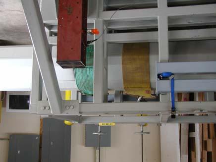


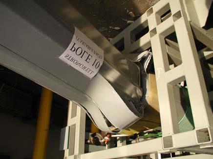
28 APPENDIX B TEST PHOTOGRAPHS Test Setup Test Setup Pole under load Test Setup Test Setup Test Setup Test Setup 28


29 Failure Test #5 Failure Test #7 Failure Test #3 Failure Test #4 Failure Test #1 Failure Test #2 29


30 Failure Test #1 Failure Test #11 Failure Test #8 Failure Test #9 3
Full-Scale Cyclic Bending Test of Strongwell s SE28 FRP Pole
 Test Report: Full-Scale Cyclic Bending Test of Strongwell s SE28 FRP Pole Submitted to: May 2003 EDM International, Inc. i Table of Contents 1.0 INTRODUCTION... 3 2.0 POLE PREPARATION... 3 3.0 TEST SETUPS...
Buckling Strength Tests of Strongwell s SE28 Fiberglass-Reinforced Polymer Poles
 Test Report: Buckling Strength Tests of Strongwell s SE28 Fiberglass-Reinforced Polymer Poles Submitted to: May 2003 EDM International, Inc. Table of Contents 1.0 INTRODUCTION... 3 2.0 POLE PREPARATION...
CHAPTER III DYNAMIC BEHAVIOR OF A LABORATORY SPECIMEN
 CHAPTER III DYNAMIC BEHAVIOR OF A LABORATORY SPECIMEN To address the vibration response of a long span deck floor system, an experiment using a specimen that resembles the conditions found in the in-situ
Page 1 of 46 Exam 1. Exam 1 Past Exam Problems without Solutions NAME: Given Formulae: Law of Cosines: C. Law of Sines:
 NAME: EXAM 1 PAST PROBLEMS WITHOUT SOLUTIONS 100 points Tuesday, September 26, 2017, 7pm to 9:30 You are allowed to use a calculator and drawing equipment, only. Formulae provided 2.5 hour time limit This
Metal-plate connections loaded in combined bending and tension
 Metal-plate connections loaded in combined bending and tension Ronald W. Wolfe Abstract This study evaluates the load capacity of metal-plate connections under combined bending and axial loads and shows
research report Estimating the Response of Cold-Formed Steel Frame Shear Walls RESEARCH REPORT RP REVISION 2006
 research report Estimating the Response of Cold-Formed Steel Frame Shear Walls RESEARCH REPORT RP03-7 2003 REVISION 2006 American Iron and Steel Institute Estimating the Response of Cold-Formed Steel Frame
Stay Tuned! Practical Cable Stayed Bridge Design
 midas Civil Stay Tuned! Practical Cable Stayed Bridge Design 2017 Francesco Incelli I. Introduction II. Modeling of the cable-stayed bridge a. Bridge wizard b. Girder Cross Section III. Nonlinear Effect
EXPERIMENTAL INVESTIGATION OF WOOD NAILER TOP CHORD ATTACHMENTS FOR OPEN WEB STEEL JOISTS
 EXPERIMENTAL INVESTIGATION OF WOOD NAILER TOP CHORD ATTACHMENTS FOR OPEN WEB STEEL JOISTS Michael J. Martignetti 1, Shawn P. Gross 2, Sameer S. Fares 3, David W. Dinehart 4, Joseph R. Yost 5 ABSTRACT:
FINITE ELEMENT ANALYSIS OF REINFORCED CONCRETE BRIDGE PIER COLUMNS SUBJECTED TO SEISMIS LOADING
 FINITE ELEMENT ANALYSIS OF REINFORCED CONCRETE BRIDGE PIER COLUMNS SUBJECTED TO SEISMIS LOADING By Benjamin M. Schlick University of Massachusetts Amherst Department of Civil and Environmental Engineering
Structural Performance of 8-inch NRG Concrete Masonry Units. Report Compiled for: Niagara Regional Group. Date: January 28, 2013
 Structural Performance of 8-inch NRG Concrete Masonry Units Report Compiled for: Niagara Regional Group Date: January 28, 2013 Report Prepared by: Dr. Shawn Gross, Associate Professor Dr. David Dinehart,
How Beams Work, I. Statics and Strength of Materials
 How Beams Work, I Statics and Strength of Materials HOW BEAMS WORK Beams work by transferring transverse loads along their length to their supports primarily by resisting a force called internal bending
Reproducible evaluation of material properties. Static Testing Material response to constant loading
 Material Testing Material Testing Reproducible evaluation of material properties Static Testing Material response to constant loading Dynamic Testing Material response to varying loading conditions, including
How to Design a Singly Reinforced Concrete Beam
 Time Required: 45 minutes Materials: -Engineering Paper -Calculator -Pencil -Straight Edge Design For Flexural Limit State How to Design a Singly Reinforced Concrete Beam Goal: ΦMn > Mu Strength Reduction
Reproducible evaluation of material properties. Static Testing Material response to constant loading
 Material Testing Material Testing Reproducible evaluation of material properties Static Testing Material response to constant loading Dynamic Testing Material response to varying loading conditions, including
Pole Groundline Reinforcement System for Transmission and Distribution Poles
 Laminated Wood Systems, Inc. Pole Groundline Reinforcement System for Transmission and Distribution Poles Laminated Wood Systems, Inc. 800-949-3526 The patented PoleEnforcer proves that all steel is NOT
SHEAR AND BUCKLING STRENGTHENING OF STEEL BRIDGE GIRDER USING SMALL-DIAMETER CFRP STRANDS
 20 th International Conference on Composite Materials Copenhagen, 19-24 th July 2015 SHEAR AND BUCKLING STRENGTHENING OF STEEL BRIDGE GIRDER USING SMALL-DIAMETER CFRP STRANDS Hamid Kazem 1, Sami Rizkalla
SEISMIC REHABILITATION OF REINFORCED CONCRETE BRIDGE COLUMNS IN MODERATE EARTHQUAKE REGIONS USING FRP COMPOSITES
 13 th World Conference on Earthquake Engineering Vancouver, B.C., Canada August 1-6, 24 Paper No. 58 SEISMIC REHABILITATION OF REINFORCED CONCRETE BRIDGE COLUMNS IN MODERATE EARTHQUAKE REGIONS USING FRP
ADAPT PT7 TUTORIAL FOR BEAM FRAME 1
 ADAPT PT7 TUTORIAL FOR BEAM FRAME 1 Technical Note Structural Concrete Software System TN189_PT7_tutorial_beam_frame 012705 1 BEAM FRAME The objective of this tutorial is to demonstrate the step-by-step
Todd F. Shupe Associate Professor School of Renewable Natural Resources Louisiana State University AgCenter Baton Rouge, LA 70803
 FINITE ELEMENT ANALYSES OF WOOD LAMINATED COMPOSITE POLES 1 Cheng Piao Postdoctoral Research Associate USDA Forest Service Forest Products Laboratory Madison, WI 53726 Todd F. Shupe Associate Professor
FRP Specifications. Section Fiberglass Reinforced Polymer (FRP) Baffle Wall Panel Products and Fabrications REVISED 11.
 Baffle Wall Panel Products and Fabrications REVISED 11.") FRP Specifications Section 06 70 00 Fiberglass Reinforced Polymer (FRP) Baffle Wall Panel Products and Fabrications REVISED 11.2016 BRISTOL FACILITY 400 Commonwealth Ave., P. O. Box 580, Bristol, VA 24203-0580
FRP Specifications Section 06 70 00 Fiberglass Reinforced Polymer (FRP) Baffle Wall Panel Products and Fabrications REVISED 11.2016 BRISTOL FACILITY 400 Commonwealth Ave., P. O. Box 580, Bristol, VA 24203-0580
GREEN THREAD Piping Systems
 Bulletin No. A1300 February 15, 2006 SMITH FIBERCAST GREEN THREAD Piping Systems PRODUCT GREEN THREAD pipe is filament wound using an amine cured epoxy resin and fiberglass and has a resin-rich liner reinforced
RStandard Pole Design Guide
 RStandard Pole Design Guide General Methodologies and Procedures for Structure Design using RStandard Modular Composite Poles and PLS-Pole Rev. Description Date Compiled By A Issue for External Customer
Introduction. Crossarm Design
 SUBJECT BCTC 287kV H-Frame Crossarm Finite Element Analysis Report AUTHOR Jeremy Mostoller DATE August 4, 2008 Introduction This report details the analysis and optimization of the glass fiber reinforced
477 kcmil, 3M Brand Composite Conductor Mechanical Properties, Volume 1 Tensile and Stress-Strain Tests
 477 kcmil, 3M Brand Composite Conductor Mechanical Properties, Volume 1 Tensile and Stress-Strain Tests Minnesota Mining and Manufacturing (3M) Company Purchase Order 0000227040 NEETRAC Project Number:
PanelMSR An on-line stiffness tester for engineered wood panels
 PanelMSR An on-line stiffness tester for engineered wood panels Lister, Peter F. 1, Lau, Kenneth K. 2 ABSTRACT CAE Machinery Ltd. has developed a non-destructive on-line tester for measuring panel bending
QUIZ 2 Allotted Time: 3 hours
 ARCHITECTURE 324/624: INTRODUCTION TO STRUCTURAL DESIGN PAGE 1 Name print QUIZ 2 Allotted Time: 3 hours On my honor as a student, I pledge the following: I will neither give nor receive unauthorized assistance
BEAMS: COMPOSITE BEAMS; STRESS CONCENTRATIONS
 BEAMS: COMPOSITE BEAMS; STRESS CONCENTRATIONS Slide No. 1 Bending of In the previous discussion, we have considered only those beams that are fabricated from a single material such as steel. However, in
Merrimack and Suwannee ACSS/TW/HS285 Conductor Stress-Strain Tests. Southwire Company
 Merrimack and Suwannee ACSS/TW/HS285 Conductor Stress-Strain Tests Southwire Company NEETRAC Project Number: 05-204 November, 2005 A Research Center of the Georgia Institute of Technology Requested by:
Client Project Job # Wall Loc. SBWall Report deg 120 pcf 950 psf deg 0.0 ft. 6.0 ft 6.0 ft 2.0 ft. W16x50.
 SBWall Report Soils Data Soil Friction Angle, phi Soil Unit Weight, gamma Soil Surcharge (uniform), qs Passive Resistance, FSp Passive Wedge Width, PW*B Backfill Slope Angle, beta Ignore Passive Resistance,
Part 4 MECHANICAL PROPERTIES
 Part 4 MECHANICAL PROPERTIES Fiber Composite Materials M. S. Ahmadi 192 TENSILE PROPERTIES Tensile properties, such as tensile strength, tensile modulus, and Poisson s ratio of flat composite laminates,
CHAPTER 4. 1:6-Scale Frame: Stiffness and Modal Testing 4.1 OVERVIEW
 CHAPTER 4 1:6-Scale Frame: Stiffness and Modal Testing 4.1 OVERVIEW A 1:6-scale steel moment frame was designed for shaking-table experiments described in Chapter 5 based on Drain-2DX (DRAIN) analyses.
ADAPT PT7 TUTORIAL FOR ONE-WAY SLAB 1
 Structural Concrete Software System TN187_PT7_tutorial_one_way_slab 012705 ADAPT PT7 TUTORIAL FOR ONE-WAY SLAB 1 1. ONE-WAY SLAB SUPPORTED ON BEAMS The objective of this tutorial is to demonstrate the
FRP Specifications. Section Fiberglass Reinforced Polymer (FRP) Hollow Core Building Panels Products and Fabrications REVISED 11.
 Hollow Core Building Panels Products and Fabrications REVISED 11.") FRP Specifications Section 06 70 00 Fiberglass Reinforced Polymer (FRP) Hollow Core Building Panels Products and Fabrications REVISED 11.2016 BRISTOL FACILITY 400 Commonwealth Ave., P. O. Box 580, Bristol,
FRP Specifications Section 06 70 00 Fiberglass Reinforced Polymer (FRP) Hollow Core Building Panels Products and Fabrications REVISED 11.2016 BRISTOL FACILITY 400 Commonwealth Ave., P. O. Box 580, Bristol,
SPECIFICATIONS FOR THE CONSTRUCTION OF NEW PASSENGER EQUIPMENT CARS PREFACE
 SPECIFICATIONS FOR THE CONSTRUCTION OF NEW PASSENGER EQUIPMENT CARS Standard ADOPTED 1939; ADVANCED TO STANDARD, 1945. PREFACE The specifications have been prepared on the basis that they will be used
Introduction to Substation Design TADP 542
 Introduction to Substation Design TADP 542 Substation Structures- Introduction Instructor: Dr. Yenumula Prasad Transmission & Distribution Program Substation Structures Reference Substation Structure Design
Ductile FRP Strengthening Systems
 Ductile FRP Strengthening Systems Hybridization allows strengthening of reinforced concrete beams without drawbacks typical of fiber-reinforced polymer systems BY NABIL F. GRACE, WAEL F. RAGHEB, AND GEORGE
FULL-SCALE SHEAR WALL TESTS FOR FORCE TRANSFER AROUND OPENINGS. T Skaggs Borjen Yeh APA The Engineered Wood Association U.S.A.
 CIB-W18/43-15-5 INTERNATIONAL COUNCIL FOR RESEARCH AND INNOVATION IN BUILDING AND CONSTRUCTION WORKING COMMISSION W18 - TIMBER STRUCTURES FULL-SCALE SHEAR WALL TESTS FOR FORCE TRANSFER AROUND OPENINGS
Characteristic values of pultruded fibre composite sections for structural design
 Southern Cross University epublications@scu 23rd Australasian Conference on the Mechanics of Structures and Materials 2014 Characteristic values of pultruded fibre composite sections for structural design
DURABILITY PERFORMANCE OF EPOXY INJECTED REINFORCED CONCRETE BEAMS WITH AND WITHOUT FRP FABRICS
 DURABILITY PERFORMANCE OF EPOXY INJECTED REINFORCED CONCRETE BEAMS WITH AND WITHOUT FRP FABRICS Prof. John J. Myers Associate Professor CIES / Department of Civil, Arch., & Env. Engineering University
BUCKLING ANALYSIS OF PULTRUDED GFRP HOLLOW BOX BEAM
 BUCKLING ANALYSIS OF PULTRUDED GFRP HOLLOW BOX BEAM Donna CHEN Ph.D. Candidate University of Calgary, Department of Civil Engineering 2500 University Drive NW, Calgary, Alberta, T2N 1N4, Canada dsmchen@ucalgary.ca
2005 AWPA Annual Meeting New Orleans, LA May Nelson G. Bingel III. Chair - ANSI O5 Principal - NESC
 2005 AWPA Annual Meeting New Orleans, LA May 15-18 ANSI - NESC Update Nelson G. Bingel III Chair - ANSI O5 Principal - NESC ANSI O5 - Material NESC - Safety WOOD QUALITY CLASS LOADS FIBER STRESS POLE DIMENSIONS
JPods, LLC. Cost Estimate. Structural Support Systems. for 12/08/06 SHEET N 1 OF 16 CALC N
 1 OF 16 12/08/06 Cost Estimate of Structural Support Systems for JPods, LLC 2 OF 16 TABLE OF CONTENTS SUBJECT: PAGE 1. Purpose.. 3 2. Methodology. 3. 3. Assumptions. 4 4. Input Data... 5 5. Loading Combinations
Mechanical Springs Shigley Ch 10 Lecture 21
 Mechanical Springs Shigley Ch 10 Lecture 21 Why do we need springs? Flexibility of structure Storing and releasing of energy Mechanical Springs Standard spring types: Wire springs -Helical springs of round
MECHANICAL PROPERTIES AND TESTS. Materials Science
 MECHANICAL PROPERTIES AND TESTS Materials Science Stress Stress is a measure of the intensity of the internal forces acting within a deformable body. Mathematically, it is a measure of the average force
Chlorine Contact Basin at Keegan s Bayou WWTP, Houston, TX
 Glass Steel, InC. 1 FIBERGLASS BAFFLE WALL SYSTEMS Chlorine Contact Basin at Keegan s Bayou WWTP, Houston, TX Glass Steel, Inc. PO Box 7155 The Woodlands, TX 77387-7155 18468 FM 1314 Conroe, TX 77302 (281)
Test Results: HC Beam for the Knickerbocker Bridge AEWC Report Project 671 September 2009
 Test Results: HC Beam for the Knickerbocker Bridge September 2009 Submitted by: Thomas Snape Robert Lindyberg, Ph.D., P.E. The AEWC Advanced Structures & Composites Center conducts all testing in accordance
TEST REPORT. Rendered to: COLLINS LIMITED, LLC. For:
 TEST REPORT Rendered to: COLLINS LIMITED, LLC For: 48 in Rook Post Mount and Structural Post Assembly Report No: Report Date: 03/11/10 130 Derry Court York, PA 17406-8405 phone: 717-764-7700 fax: 717-764-4129
Engineered Design of Structural Insulated Panels (SIPs)
") PDHonline Course S244 (11 PDH) Engineered Design of Structural Insulated Panels (SIPs) Instructor: Mike J. Nelson, P.E., S.E 2012 PDH Online PDH Center 5272 Meadow Estates Drive Fairfax, VA 22030-6658
PDHonline Course S244 (11 PDH) Engineered Design of Structural Insulated Panels (SIPs) Instructor: Mike J. Nelson, P.E., S.E 2012 PDH Online PDH Center 5272 Meadow Estates Drive Fairfax, VA 22030-6658
Lateral Design of Mid- Rise Wood Structures
 Lateral Design of Mid- Rise Wood Structures Presented by Ricky McLain, MS, PE, SE Technical Director WoodWorks Texas Workshops December, 2016 Insert picture of me graduating college Follow the load Following
Appendix D.1. Redundancy Analysis of Composite Spread Box Girder Superstructures under Vertical Loads
 Appendix D.1 Redundancy Analysis of Composite Spread Box Girder Superstructures under Vertical Loads By Jian Yang, Feng Miao and Michel Ghosn Contents 1. Introduction...1 2. Structural Modeling...3 2.1
M.S. Comprehensive Examination: Design
 UNIVERSITY OF CALIFORNIA, BERKELEY Dept. of Civil and Environmental Engineering Spring Semester 2017 M.S. Comprehensive Examination: Design Consider the shown frame and the cross-section of the column
E APPENDIX. The following problems are intended for solution using finite element. Problems for Computer Solution E.1 CHAPTER 3
 E APPENDIX Problems for Computer Solution The following problems are intended for solution using finite element analysis software. In general, the problems associated with Chapters 3, 4, and 9 can be solved
On the Structural Responses of Simply Supported PFRP Channel Beams under Three-point Loading
 International Journal of Civil & Environmental Engineering IJCEE-IJENS Vol: 11 No: 4 13 On the Structural Responses of Simply Supported PFRP Channel Beams under Three-point Loading Jaksada Thumrongvut
Testing and Evaluation of CFS L-headers
 Missouri University of Science and Technology Scholars' Mine International Specialty Conference on Cold- Formed Steel Structures (2008) - 19th International Specialty Conference on Cold-Formed Steel Structures
Erector Connector Meadow Burke Company In- Plane Performance
 Lehigh University Lehigh Preserve ATLSS Reports Civil and Environmental Engineering 1-1-2007 Erector Connector Meadow Burke Company In- Plane Performance Clay Naito Follow this and additional works at:
Allowable Loads for Round Timber Poles
 UNIVERSITY OF ALASKA FAIRBANKS Allowable Loads for Round Timber Poles HCM-00752 UNIVERSITY OF ALASKA FAIRBANKS The following publication is a major upgrade of information for calculating and understanding
Basic quantities of earthquake engineering. Strength Stiffness - Ductility
 Basic quantities of earthquake engineering Strength Stiffness - Ductility 1 Stength is the ability to withstand applied forces. For example a concrete element is weak in tension but strong in compression.
3. Multi Span beam simply supported at multiple locations (All deck products listed)
") July 31, 2012 398 East Dania Beach Blvd. Suite 338 Dania Beach, FL 33004 954.399.8478 PH 954.744.4738 FX contact@buildingdrops.com Manufacturer: 1604 Athens Highway Gainesville, GA 30507 Report: PER 2144
July 31, 2012 398 East Dania Beach Blvd. Suite 338 Dania Beach, FL 33004 954.399.8478 PH 954.744.4738 FX contact@buildingdrops.com Manufacturer: 1604 Athens Highway Gainesville, GA 30507 Report: PER 2144
FAILURE OF PULTRUDED GRP ANGLE-LEG JUNCTIONS IN TENSION
 FAILURE OF PULTRUDED GRP ANGLE-LEG JUNCTIONS IN TENSION G.J. Turvey* and P. Wang** * Engineering Department, Lancaster University, Bailrigg, Lancaster, LA1 4YR, UK g.turvey@lancaster.ac.uk ** Schlumberger,
Exploratory Investigation of Failure Mechanisms in Transition Regions between Solid Laminates and X-cor Truss Sandwich
 Exploratory Investigation of Failure Mechanisms in Transition Regions between Solid Laminates and X-cor Truss Sandwich Abstract T. Kevin O Brien* Isabelle L. Paris** NASA Langley Research Center Hampton,
Centricast CL-1520 Pipe Product Data
 Centricast CL-1520 Pipe Product Data Product Name 14/15 CHEMICAL INDUSTRIAL Applications Acids Salts Oxidizing Agents Chloride Water Materials and Construction All pipe is manufactured with glass fabrics
Interaction Testing Report. 24 SF Units with Synteen Geogrids. Stone Strong Systems Lincoln, Nebraska
 Interaction Testing Report 24 SF Units with Synteen Geogrids Stone Strong Systems Lincoln, Nebraska Prepared for: Stone Strong Systems 1620 South 70th Street Suite 105 Lincoln, Nebraska 68506 September
four design methods & beams APPLIED ACHITECTURAL STRUCTURES: DR. ANNE NICHOLS SPRING 2018 lecture STRUCTURAL ANALYSIS AND SYSTEMS ARCH 631
 APPLIED ACHITECTURAL STRUCTURES: STRUCTURAL ANALYSIS AND SYSTEMS DR. ANNE NICHOLS SPRING 2018 lecture four design methods & beams Forum, Pompeii Methods & Beams 1 Allowable Stress Design historical method
ADAPT-PT 2010 Tutorial Idealization of Design Strip in ADAPT-PT
 ADAPT-PT 2010 Tutorial Idealization of Design Strip in ADAPT-PT Update: April 2010 Copyright ADAPT Corporation all rights reserved ADAPT-PT 2010-Tutorial- 1 Main Toolbar Menu Bar View Toolbar Structure
ENGINEERING SPECIFICATIONS
 ENGINEERING SPECIFICATIONS REINFORCED CONCRETE FILL Units 800 Series Factored Moment Capacities with1, 2 and 4 rebar Bending Stiffness with1, 2 and 4 rebar Factored Shear Capacities See tables 1, 4 and
MECHANICAL BRIDGING AND BRIDGING ANCHORAGE OF LOAD BEARING COLD-FORMED STEEL STUDS. Paul E. Lackey, EIT Nabil A. Rahman, Ph.D.
 INTRODUCTION MECHANICAL BRIDGING AND BRIDGING ANCHORAGE OF LOAD BEARING COLD-FORMED STEEL STUDS Paul E. Lackey, EIT Nabil A. Rahman, Ph.D., PE Gary Bennett The purpose of this technical note is to provide
MECHANICAL CHARACTERIZATION OF SANDWICH STRUCTURE COMPRISED OF GLASS FIBER REINFORCED CORE: PART 2
 Composites in Construction 2005 Third International Conference Lyon, France, July 11 13, 2005 MECHANICAL CHARACTERIZATION OF SANDWICH STRUCTURE COMPRISED OF GLASS FIBER REINFORCED CORE: PART 2 S.V. Rocca
UNION STATION EXPANSION AND RESTORATION
 UNION STATION EXPANSION AND RESTORATION WASHINGTON DC TECHNICAL REPORT III: LATERAL SYSTEM ANALYSIS Prepared By: Joseph W. Wilcher III Prepared For: M.K. Parfitt November 21, 2008 TABLE OF CONTENTS Addendum...
A Guide for the Interpretation of Structural Design Options for Residential Concrete Structures
 CFA Technical Note: 008-2010 A Guide for the Interpretation of Structural Design Options for Residential Concrete Structures CFA Technical This CFA Technical Note is intended to serve as a guide to assist
Modjeski and Masters, Inc. Consulting Engineers 04/18/06 St. Croix River Bridge 3D Analysis Report Introduction
 Introduction This memo presents a summary of a three dimensional (3D) analysis of the Organic concept for the proposed St. Croix River bridge project. The Organic concept has several attributes that are
Structural Engineering, Mechanics, and Materials. Preliminary Exam - Structural Design
 Fall Semester 2018 Preliminary Exam - Structural Design A small building is located in downtown Berkeley. The structural system, either structural steel or reinforced concrete, comprises gravity framing
COMPARISON OF MULTISTORY WALL RESULTS BETWEEN ADAPT-EDGE 1 AND ETABS 2 CONCRETE FRAME WITH SHEARWALLS
 Your Partner in Structural Concrete Design TN500_EDGE_Etabs_Comp_06132016 COMPARISON OF MULTISTORY WALL RESULTS BETWEEN ADAPT-EDGE 1 AND ETABS 2 CONCRETE FRAME WITH SHEARWALLS INTRODUCTION This Technical
Behavior of Concrete/Cold Formed Steel Composite Beams: Experimental Development of a Novel Structural System
 International Journal of Concrete Structures and Materials Vol.7, No.1, pp.51 59, March 2013 DOI 10.1007/s40069-013-0031-6 ISSN 1976-0485 / eissn 2234-1315 Behavior of Concrete/Cold Formed Steel Composite
Sheetpile Wall Report
 16 ft cut Sheetpile Wall Report Project Information Designed By: LAA Organization: 16 ft cut Date: 05/09/2012 Project: Job #: 4952-6 Client: Support condition = Cantilever Unit system = English (ft, lb,
Deflection Assessment of an FRP-Reinforced Concrete Bridge. By Danielle K. Stone, Andrea Prota, and Antonio Nanni
 Deflection Assessment of an FRP-Reinforced Concrete Bridge By Danielle K. Stone, Andrea Prota, and Antonio Nanni Synopsis: Serviceability of FRP-reinforced concrete structures remains a highly relevant
Marina Bay Sands Hotel Arch 631 Kayla Brittany Maria Michelle
 Marina Bay Sands Hotel Arch 631 Kayla Brittany Maria Michelle Overall Information Location: Singapore Date of Completion: 2010 Cost: $5.7 billion Architect: Moshe Safdie Executive Architect: Aedas, Pte
MECHANICAL PROPERTIES OF MATERIALS
 MECHANICAL PROPERTIES OF MATERIALS Stress-Strain Relationships Hardness Effect of Temperature on Properties Fluid Properties Viscoelastic Behavior of Polymers Mechanical Properties in Design and Manufacturing
Learning Objectives. Copyright Materials. This presentation is protected by US and International Copyright laws. Reproduction,
 The Wood Products Council is a Registered Provider with The American Institute of Architects Continuing Education Systems (AIA/CES). Credit(s) earned on completion of this program will be reported to AIA/CES
Safety in a Second Guardrail Testing
 BMT Fleet Technology Limited 21017.DB01 (Rev. DRAFT01) Safety in a Second Guardrail Testing Reference: 7830.FR (Issue 02) Date: 19 March 2012 BMT Fleet Technology Limited accepts no liability for any errors
Application of Tensioned CFRP Strip Method to an Existing Bridge
 SP-230 66 Application of Tensioned CFRP Strip Method to an Existing Bridge by A. Tateishi, A. Kobayashi, Y. Hamada, T. Takahashi, and H. Yasumori Synop nopsis: s: Tensioned carbon fiber reinforced polymer
THE USE OF CARBON FIBER REINFORCED ALUMINUM TO STIFFEN A PORTALEDGE STRUCTURE
 The University of Akron IdeaExchange@UAkron Honors Research Projects The Dr. Gary B. and Pamela S. Williams Honors College Spring 2015 THE USE OF CARBON FIBER REINFORCED ALUMINUM TO STIFFEN A PORTALEDGE
COMPOSITES & POLYCON American Composites Manufacturers Association January 15-17, 2009 Tampa, FL USA. Abstract. Introduction.
 American Composites Manufacturers Association January 15-17, 2009 Tampa, FL USA Behavior of Natural-Fiber/Thermoplastic Sheet Piling Daniel Alvarez-Valencia, Habib J. Dagher, Roberto A. Lopez-Anido, William
(laboratory) (fall semester)
 (fall semester)") Civil Engineering Courses-1 CIV 211/Surveying Prerequisite: MAT 127 An introduction to the theory and applications of modern surveying processes. Students use optical and digital land surveying instruments
Civil Engineering Courses-1 CIV 211/Surveying Prerequisite: MAT 127 An introduction to the theory and applications of modern surveying processes. Students use optical and digital land surveying instruments
CH. 9 WOOD CONSTRUCTION
 CH. 9 WOOD CONSTRUCTION PROPERTIES OF STRUCTURAL LUMBER Grading Load carrying capacity effected by: - Size and number of knots, splits & other defects - Direction of grain - Specific gravity of wood Grading
EFFECT OF VENEER JOINT REINFORCEMENT ON BRICK TIE EMBEDMENT
 EFFECT OF VENEER JOINT REINFORCEMENT ON BRICK TIE EMBEDMENT William McEwen, 1 Ari Wibowo, 2 Perry Adebar, 2 and Donald Anderson 2 ABSTRACT Some building codes require single wire joint reinforcement in
Axial load-bending moment diagrams of GFRP reinforced columns and GFRP encased square columns
 University of Wollongong Research Online Faculty of Engineering and Information Sciences - Papers: Part A Faculty of Engineering and Information Sciences 2017 Axial load-bending moment diagrams of GFRP
Effect of Paperboard Stress-Strain Characteristics on Strength of Singlewall Corrugated Fiberboard:
 United States Department of Agriculture Forest Service Forest Products Laboratory Research Paper FPL 401 Effect of Paperboard Stress-Strain Characteristics on Strength of Singlewall Corrugated Fiberboard:
four design methods & beams Allowable Stress Design Limit State Design Allowable Stress Design
 APPLIED ARCHITECTURAL STRUCTURES: STRUCTURAL ANALYSIS AND SYSTES DR. ANNE NICHOLS FALL 013 lecture four Allowable Stress Design historical method a.k.a. working stress, stress design stresses stay in ELASTIC
LOAD TESTS ON 2-SPAN REINFORCED CONCRETE BEAMS STRENGTHENED WITH FIBRE REINFORCED POLYMER
 LOAD TESTS ON 2-SPAN REINFORCED CONCRETE BEAMS STRENGTHENED WITH FIBRE REINFORCED POLYMER Lander Vasseur 1, Stijn Matthys 2, Luc Taerwe 3 Department of Structural Engineering, Ghent University, Magnel
ADAPT-PTRC 2016 Getting Started Tutorial ADAPT-PT mode
 ADAPT-PTRC 2016 Getting Started Tutorial ADAPT-PT mode Update: August 2016 Copyright ADAPT Corporation all rights reserved ADAPT-PT/RC 2016-Tutorial- 1 This ADAPT-PTRC 2016 Getting Started Tutorial is
STRUCTURAL EDGE ENGINEERING, PLLC
 JEREMY PARRISH Registered Professional Engineer In Partners with STRUCTURAL EDGE ENGINEERING, PLLC STRUCTURAL EDGE ENGINEERING, PLLC HINES PARK BUILDING A NAMPA, ID SE PROJECT NO: SE16-177 PREPARED FOR:
STRESS-RIBBON BRIDGES STIFFENED BY ARCHES OR CABLES
 2nd Int. PhD Symposium in Civil Engineering 1998 Budapest STRESS-RIBBON BRIDGES STIFFENED BY ARCHES OR CABLES Tomas Kulhavy Technical University of Brno, Department of Concrete and Masonry Structures Udolni
BROADSPAN. LVL Design Brochure. Design properties for LVL header and beam applications in the U.S. for residential floor and roof systems
 BROADSPAN LVL Design Brochure Design properties for LVL header and beam applications in the U.S. for residential floor and roof systems LVL Design Brochure Product Line You ve probably been building with
Earthquake Design of Flexible Soil Retaining Structures
 Earthquake Design of Flexible Soil Retaining Structures J.H. Wood John Wood Consulting, Lower Hutt 207 NZSEE Conference ABSTRACT: Many soil retaining wall structures are restrained from outward sliding
CH 6: Fatigue Failure Resulting from Variable Loading
 CH 6: Fatigue Failure Resulting from Variable Loading Some machine elements are subjected to statics loads and for such elements, statics failure theories are used to predict failure (yielding or fracture).
In-Plane and Out-of-Plane Performance of the MINI-MC Flange Connector
 Lehigh University Lehigh Preserve ATLSS Reports Civil and Environmental Engineering 7-1-2009 In-Plane and Out-of-Plane Performance of the MINI-MC Flange Connector Clay Naito Ruirui Ren Follow this and
Project ULA 120D Snow-0 Seis-IV
 ULA Geometry Module Specification Sub-Array Configuration ULA Totals # Rows: 4 Column N-S Length (in): 6 # SubArrays: N-S Dim (in): 40 N-S Spacing (in): 0.25 # Columns: 5 Array E-W Dimension (in): 326
Behavior of Continuous Span Purlin Systems
 Missouri University of Science and Technology Scholars' Mine International Specialty Conference on Cold- Formed Steel Structures (1988) - 9th International Specialty Conference on Cold-Formed Steel Structures
CAPACITY OF ANCHOR BOLTS IN CONCRETE MASONRY
 13 th International Brick and Block Masonry Conference Amsterdam, July 4-7, 2004 CAPACITY OF ANCHOR BOLTS IN CONCRETE MASONRY W. Mark McGinley 1 Scott Singleton 2, Jeff Greenwald 3 and Jason Thompson 4
Technical Notes 39A - Testing for Engineered Brick Masonry - Determination of Allowable Design Stresses [July/Aug. 1981] (Reissued December 1987)
![Technical Notes 39A - Testing for Engineered Brick Masonry - Determination of Allowable Design Stresses [July/Aug. 1981] (Reissued December 1987)](/thumbs/75/72632512.jpg "Technical Notes 39A - Testing for Engineered Brick Masonry - Determination of Allowable Design Stresses [July/Aug. 1981] (Reissued December 1987)") Technical Notes 39A - Testing for Engineered Brick Masonry - Determination of Allowable Design Stresses [July/Aug. 1981] (Reissued December 1987) INTRODUCTION Prior to the development of a rational design
Technical Notes 39A - Testing for Engineered Brick Masonry - Determination of Allowable Design Stresses [July/Aug. 1981] (Reissued December 1987) INTRODUCTION Prior to the development of a rational design