Kiva Fireplace GAS BURNING INSTALLATION MANUAL
|
|
|
- Gervais Thomas
- 6 years ago
- Views:
Transcription

 KIVA FIREBOX A pre cast firebox consisting of real hand laid firebrick and lightweight concrete.")
 B VENT CHIMNEY Lightweight 6 type B Vent chimney is used for venting the fireplace.")
1 Kiva Fireplace GAS BURNING INSTALLATION MANUAL Frame Models: Orno Santa Fe Navajo Zuni Keep these instructions for future use. C This fireplace is to be installed ONLY by a construction industry licensed contractor. Any permits and construction industry inspections required for installation should be obtained by this contractor. B The Adobelite Fireplace System consists of: A) KIVA FIREBOX A pre cast firebox consisting of real hand laid firebrick and lightweight concrete. B) EXTERIOR FIREPLACE FRAME A tubular steel and diamond mesh frame. The frame is finished with stucco after installation. A C) B VENT CHIMNEY Lightweight 6 type B Vent chimney is used for venting the fireplace. D D) GAS LOG SYSTEM Electronic Ignition Gas Log Burning System is operated by a wall switch or remote. E) FIREBOX PEDESTAL Concrete blocks are used to elevate the firebox. E NOTE: All warnings are outlined in this manual and must be adhered to by the installer and the buyer. Failure to do so will nullify the manufacturer s warranty, and may cause serious fire hazard. RV
2 WARNINGS AND GENERAL SAFETY PRECAUTIONS IMPORTANT: THESE INSTRUCTIONS MUST BE LEFT WITH HOMEOWNER ALL WARNINGS OUTLINED IN THIS MANUAL MUST BE STRICTLY ADHERED TO BY THE INSTALLER AND HOMEOWNER. FAILURE TO FOLLOW these installation instructions will VOID THE WARRANTY and may cause a serious FIRE HAZARD. This fireplace is to be installed ONLY by a construction industry licensed contractor. Any permits and construction industry inspections required for installation should be obtained by this contractor. Fully READ and UNDERSTAND all instructions carefully before beginning installation. DO NOT modify your fireplace in any way. Any modification will void the warranty and create a potential fire hazard. Before burning your first fire, fully read the Homeowners Operation Manual. Combustion Air Intake of fireplace must be kept clear of debris at all times. Do not store or use flammable liquids or aerosols near this fireplace. Never leave the fireplace burning while unattended. Children should never be left unattended while the fireplace is in use. WARNING: Only use approved chimney and termination systems outlined in this manual. WARNING: This fireplace is NOT designed for wall termination. Fireplace must be vented vertically. 2
3 TABLE OF CONTENTS Warning and Safety Precautions Listing Data Plate / Location Pre Installation Requirements..5 Firebox Dimensions.5,6 Chimney Requirements.6 Gas Requirements Electrical Requirements...8 Fireplace Layout.8,9 Fireplace Pedestal Firebox Installation.. 10 Firebox Assembly Door Frame Anchor Plate Chimney Installation 12 Installing the Chimney Pipe Outside Air Kit Installation Kiva Frame Installation Finishing the Fireplace...17 Lava Rock / Gas Log Setup Operation and Trouble Shooting Adobelite Kiva Fireplace Options..20 3


4 LISTING DATA PLATE / LOCATION The Adobelite Kiva Fireplace is a factory built fireplace tested to U.L Locate the Listing Data Plate inside the manifold by opening the hinged access door at the bottom of the door frame. Record the model, size, and serial number listed on the data plate below. MODEL TYPE / SIZE SERIAL NUMBER FIG. 1 LISTING DATA PLATE LOCATION PLEASE FILL IN THE FOLLOWING INFORMATION FOR FUTURE REFERENCE Model Type / Size: Date Purchased: Date Installed: Frame Style: Dealership Purchased at: Serial Number: Dealership Phone #: Chimney Pipe Brand: Chimney Pipe Size (Inner/Outer): Notes: 4


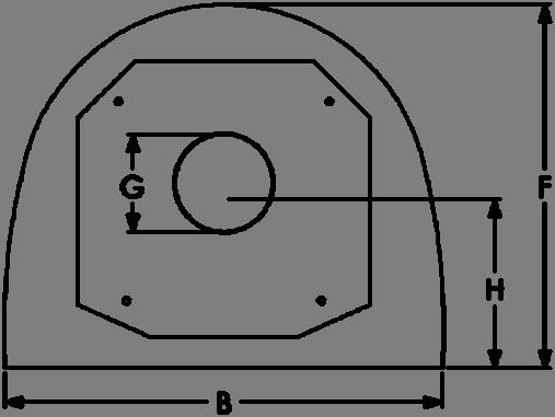

5 PRE INSTALLATION REQUIREMENTS 1 KIVA18 FIREBOX DIMENSIONS: TOP VIEW CLEARANCES TO COMBUSTIBLES SIDES/BACK 1 FACE All framing along firebox face must be non combustible CHIMNEY 1 A B C D E F G H KIVA / / / 2 6 MIN / 2 KIVA24 FIREBOX DIMENSIONS: TOP VIEW CLEARANCES TO COMBUSTIBLES SIDES/BACK 1 FACE All framing along firebox face must be non combustible CHIMNEY 1 A B C D E F G H KIVA / / / 2 6 MIN / 2 5


6 KIVA30 FIREBOX DIMENSIONS: TOP VIEW CLEARANCES TO COMBUSTIBLES SIDES/BACK 1 FACE All framing along firebox face must be non combustible CHIMNEY 1 A B C D E F G H KIVA / / / MIN / 2 Fireplace installation must be in compliance with local building codes. Before installing the fireplace, consult the local construction industry to ensure that you are in compliance with all applicable codes, including permits and inspections. WARNING: THE FIREBOX MUST BE FINISHED WITH THE ADOBELITE KIVA METAL FRAME OR OTHER NON COMBUSTIBLE MATERIALS. CLEARANCES TO COMBSTIBLE MATERIALS AND FRAMING MUST BE MAINTAINED. CHIMNEY REQUIREMENTS GAS BURNING For minimum chimney sizes and types see table below. Certified equivalents tested and listed to UL Test Procedure 103, and ULC S604 may also be used if minimum chimney diameter is adhered to. Chimney Type and Sizes Minimum Clearance I.D. Chase Size KIVA 18 6 I.D. / 6 3 / 4 O.D. B Vent 1 9 x 9 minimum KIVA 24 6 I.D. / 6 3 / 4 O.D. B Vent 1 9 x 9 minimum KIVA 30 6 I.D. / 6 3 / 4 O.D. B Vent 1 9 x 9 minimum TABLE 1. chimney requirements WARNING! B Vent Chimney should never be used when solid fuels are to be burned! 6
7 GAS REQUIREMENTS: IMPORTANT: All gas connections and gas piping must be installed by a construction industry licensed contractor. Any permits and construction industry inspections required for installation should be obtained by this contractor. BTU REQUIREMENTS The Adobelite Gas Log system requires 1 / 2 gas supply line capable of supplying an input BTU of 48,000 for Natural Gas, and 39,700 for Liquid Propane. KEY VALVE Before the Adobelite firebox is installed, gas lines should be run into the area where the fireplace will be installed. A Keyed Gas Shutoff Valve is required in an accessible location within 3 of the fireplace. Use figure A, in the charts below to locate the minimum distance from the corner where the Keyed Gas Shutoff Valve can be placed to insure it will not be behind the Adobelite Frame when installed. It should also be at a minimum height of 1 8. STUB OUT The 1 / 2 gas stub out should be located at a height of 6 from the floor and a distance from the corner specified by B in the charts below. It should extend no more than 2 to 3 from the wall and be capped off until it is hooked up to the fireplace. 18 FIREBOX MODELS MODEL A (min.) B Key Valve / Switch Stub Out Ornito Santa Fe FIREBOX MODELS MODEL A (min.) B Key Valve / Switch Stub Out Orno Santa Fe Navajo Zuni FIREBOX MODELS MODEL A (min.) B Key Valve / Switch Stub Out Orno Santa Fe Navajo Zuni / 2 GAS SUPPLY LINE KEYED GAS SHUTOFF VALVE A 1 / 2 GAS STUB-OUT FIG. 1 GAS SHUTOFF AND STUB OUT 6 B ELECTRICAL BOX AND SWITCH A MILLI-VOLT WIRES 7
8 ELECTRICAL REQUIREMENTS: WARNING: LOW VOLTAGE AND 110 VAC VOLTAGE CANNOT SHARE THE SAME ELECTRICAL BOX This fireplace comes equipped with a 3 volt electronic ignition gas control system. This system includes a two D cell battery pack prewired to the gas system controls, which will provide reliable operation of the system even in the event of a power outage. Battery polarity must be correct or module damage will occur. An optional 3 volt AC transformer is available from Adobelite or your dealer for operation using 110V AC. The optional transformer and the included battery pack CANNOT both be hooked up to the control module at the same time or damage will occur. Remove batteries from the battery pack before connecting the optional transformer, and unplug the transformer before installing the batteries. ELECTRICAL BOX AND SWITCH Install an Electrical Box and Wall Switch at the desired location. Refer to FIG. 1 on page 7 to locate the minimum distance from the corner that the Switch should be located. 8 Feet of 20 AWG Milli volt wire is included prewired to the gas system controls, which is to be connected to the switch terminals. LAYOUT (FIG. 4, FIG. 5) CARPET Carpet and padding will need to be removed up to the hearth line. See FIG. 4 and FIG. 5 below. Begin the layout by drawing a center line at 45 degrees for a corner installation, or perpendicular to the wall for a flat wall installation. Next, draw the baseline (dimension D refer to FIG. 4 below and FIG. 5 on page 8) perpendicular to the center line. The base line will be aligned with the front edge of the Firebox Base and the Firebox Pedestal. CORNER LAYOUT 18 FIREBOX MODELS MODEL A B C D Frame at Ceiling Frame at Hearth Hearth Baseline Ornito Santa Fe FIREBOX MODELS MODEL A B C D Frame at Ceiling Frame at Hearth Hearth Baseline Orno Santa Fe Navajo Zuni BASE LINE 30 FIREBOX MODELS MODEL A B C D Frame at Ceiling Frame at Hearth Hearth Baseline Orno Santa Fe Navajo Zuni FIG. 4 CORNER LAYOUT CENTER LINE
9 FIREBOX PEDESTAL: Standard Hearth Height of 18 (Note: Concrete Blocks are not included with the Adobelite Fireplace Kit and must be purchased separately) Concrete Masonry Units (C.M.U) are used to construct the Firebox Pedestal. The overall height of the pedestal should be 12. A combination of two 8 x8 x16 and two 4 x8 x16 CMU can be stacked (as shown in FIG 6), or any other combination of concrete blocks can also be used as long as the overall height is 12. BASE LINE 1) Two columns of CMU s should be positioned with the front edge of the blocks against the Firebox Base Line. Refer to Block Spacing dimension (H) in positioning the width of the block pedestal. The blocks should be equally spaced from the center line. 2) Adhere the concrete blocks to each other and to the concrete slab as they are assembled using mortar or a construction adhesive such as Liquid Nails or F26. FIG. 5 FLAT WALL LAYOUT 24 FIREBOX MODELS MODEL A B C D Width at Ceiling Width at Firebox Width of Hearth Baseline Orno Santa Fe Navajo Zuni CENTER LINE E Depth at Ceiling F Depth at Firebox G Depth of Hearth For Hearth Height below 18 Concrete Floor When working on a concrete floor, the base section (shown in step 1, page 9) can be set directly on the floor if desired, for a 5 hearth height. 30 FIREBOX MODELS MODEL A B C D Width at Ceiling Width at Firebox Width of Hearth Baseline Orno Santa Fe Navajo Zuni E Depth at Ceiling F Depth at Firebox G Depth of Hearth Wood Floor The hearth height can also be lowered to 11 for a wood floor. If you plan to lower the firebox pedestal lower than 8, you must use a heat barrier consisting of: 1) a layer of 1 ¼ thick split firebrick, 2) a 16 gauge steel barrier (the same size as the base, and 3) another layer of 1 ¼ firebrick. The steel barrier should be sandwiched in between the firebrick. Only adjust the base pedestal height if: 1) you ordered a custom frame at that height, or 2) you feel comfortable performing the necessary modifications to the frame. 4 x 8 x 16 Concrete Block 8 x 8 x 16 Concrete Block 18 Firebox 24 Firebox 30 Firebox H Block Spacing H 12 Total Height WARNING: ONLY NON COMBUSTIBLE MATERIAL MAY BE USED FOR THE FIREBOX PEDESTAL! FIG. 6 FIREBOX PEDESTAL BASE LINE 9


 MANIFOLD AND GAS SYSTEM Apply a 1 wide layer of refractory mortar to the upper face")


10 FIREBOX ASSEMBLY 2 1) BASE Spread a thin layer of concrete mortar or construction adhesive on the top of the firebox pedestal. Place the firebox base on the pedestal. Using the layout sketch, align the front of the base with the firebox base line and center the firebox along the center line. Make sure the Base is level. 2) LOWER BACK Apply a 5 wide thin layer of the included refractory mortar to the outside top edge of the base where the Lower Back will rest. Place the Lower Back in place and rotate the piece slightly back and forth to squish the mortar into place. Align the back and sides of the Lower Back and Base. 3) UPPER BACK (MODELS KIVA24 AND KIVA30 ONLY) Following the above procedure, spread a layer of refractory mortar and place the Upper Back section on top of the Lower Back. Again, align the back and sides of the pieces. 4) MANIFOLD AND GAS SYSTEM Apply a 1 wide layer of refractory mortar to the upper face of the fireplace base. Position the Manifold so that the face of the Manifold is against the face of the base, and the L Bracket (that supplies combustion air) is resting on the firebrick surface of the Base. The Burn Pan and Kiva Grate will rest on the Base towards the back. Using the supplied ¼ x 3 lag bolts, bolt the manifold to the Base. The heads of the bolts will pass through the face of the manifold and tighten against the back of the manifold. Do Not Over tighten the Bolts! Using your finger, apply refractory mortar to all the seams where the manifold touches the Base Base Burn Pan and Kiva Grate 4 L Bracket 2 Lower Back 3 Upper Back ¼ dia. x 3 lag bolts 6 4 Manifold and Gas System 5) FRONT ARCH Apply refractory mortar to the front edges of the Lower and Upper Back pieces and to the top of the Front Arch section. Place the Front Arch into place and attach using four 1 / 4 x 6 Lag Bolts. Avoid placing any weight onto the Manifold before the bolts are attached. 6) TOP Now install the top section of the fireplace. Again, spread a thin layer of refractory mortar where the pieces will meet, and align the 5 5 Front Arch 6 Bolts 10 6 Top


")
11 FIREBOX ASSEMBLY (CONTINUED): 7) DOOR FRAME The Door Frame allows an Adobelite Screen Door or Glass Door to be used with the fireplace. Begin by attaching the Door Frame to the Manifold. Position the Door Frame on top of the Manifold and allow a 1 / 2 space between the 1 / 2 Angle Iron on the top of the Access Door and the Door Frame. Use two 1 1 / 4 x #8 self drilling (black head) screws to secure the Door Frame to the Manifold. Front Arch 7 5 Black Head Phillips Screws 1 / 2 Space Plumb the Door Frame vertically, then secure the Door Frame to the Front Arch using two 5 (black head) wood screws. 7 Access Door Finally, the Ball Catch (FIG. 7B) needs to be installed to the door frame. Begin by drilling a 1 deep x 3 / 4 dia. hole through the mounting tab and into the Front Arch. Slide the Ball Catch up into the hole and secure it to the mounting tab on the Door Frame with the two provided brass screws. 7A Door Frame 1 / 2 Angle Iron Front Arch 3 / 4 x 1 Hole 8 Anchor Plate / Damper ¼ dia. x 3 lag bolts 8 Mounting Tab Ball Catch 7 Screws 7B Ball Catch 8) B VENT ANCHOR PLATE Apply a thin layer of refractory mortar to the top of firebox where the Anchor Plate will sit. Align the back edge of the Anchor Plate opening with opening in the firebox top section. Secure the Anchor Plate using four ¼ dia. x 3 long lag bolts. 11

 with the female end of the locking lug (upper piece of pipe).")


12 CHIMNEY INSTALLATION 3 WARNING: A MINIMUM OF 1 AIR CLEARANCE MUST BE MAINTAINED BETWEEN ALL CHIMNEY COMPONENTS AND COMBSTIBLE MATERIALS. ALL INSTRUCTIONS PROVIDED BY CHIMNEY MANUFACTURERS MUST BE STRICTLY ADHERED TO. FAILURE TO PROPERLY FOLLOW ALL CLEARANCES AND INSTRUCTIONS MAY RESULT IN A SERIOUS FIRE CAUSING INJURY OR DEATH! Each section of B Vent chimney consists of an inner and outer flue pipe. As the flue sections are assembled, the upper flue section will slip to the inside of the section below. To join two sections of chimney pipe together, line up the male end slot (lower piece of pipe) with the female end of the locking lug (upper piece of pipe). Push the two sections together, and then rotate the upper piece clockwise to securely lock the two pieces together. If the chimney is pulled upward it will not separate from the pipe below if it is properly locked. Except where the first section of pipe joins to the Anchor Plate (see FIG 10), screws are not necessary to join the chimney pipe. If desired, 1 / 4 sheet metal screws may be used to secure the outer sections of chimney. Do not penetrate the inner liner! 10) STARTER ELBOW Begin the chimney installation by inserting the inside liner of the starter elbow to the inside of the Anchor Plate collar. The outside section of pipe will fit to the outside of the Anchor Plate collar. Align the inner Starter Elbow so that it points directly back away from the Firebox face. Then, secure the elbow to the Anchor Plate collar using the supplied #6 x 1 / 2 self drilling hex head screws. Do not penetrate the inner chimney liner. 11) SPACER SECTIONS Attach one or more straight sections of chimney pipe together to offset the chimney into the desired area. Refer to the Layout Charts on pages 8 and 9 to make sure the chimney is offset enough to clear the top of the Kiva Frame. A 18 section of chimney is typical for most installations. ANCHOR PLATE COLLAR 10 FIG. 10 STARTER ELBOW 11 FIG. 11 STRAIGHT SECTIONS CH LATERAL CHIMNEY SLOPE If the chimney system contains lateral (horizontal) sections, they must maintain a minimum upwards slope of 1 / 4 rise for every horizontal foot. Minimum slope of 1/4 rise per foot of run required 12

 over the Return Elbow. Then, twist lock the remaining Straight Chimney sections into place. 1 MIN. AIR SPACE TO COMBUSTIBLES!")


 FIRESTOP SPACERS Firestop Spacers are required at each point where the chimney FIG. 13 FIRESTOP SPACERS FIG.")

13 CHIMNEY INSTALLATION (CONTINUED): WARNING: CHIMNEY PIPE MUST TERMINATE VERTICALLY! IF CHIMNEY PIPE IS RUN THROUGH AN EXTERIOR WALL, A RETURN ELBOW MUST BE USED TO RETURN THE CHIMNEY TO VERTICAL, AND THE TERMINATION CAP MUST EXTEND 2 ABOVE ANY WALLS WITHIN 8 FEET! NO! YES 12) STRAIGHT CHIMNEY SECTIONS Before running the straight chimney through the roof, slide the Firestop Spacer (shown in FIG. 13) over the Return Elbow. Then, twist lock the remaining Straight Chimney sections into place. 1 MIN. AIR SPACE TO COMBUSTIBLES! 9 9 Locate and mark the center of where the chimney will pass through the ceiling or wall. Cut and frame a 9 x 9 hole for the chimney to pass through. A 1 min airspace must be maintained between the chimney pipe and all combustible materials. Chimney Enclosures: A framed enclosure is required any where the chimney passes through an occupied area. Refer to Chimney Chase Requirements on page 14 for more information. 12 Pipe strapping should be used to secure the return elbow to two studs. This will stabilize the chimney pipe and carry the weight of the straight vertical pipe ) FIRESTOP SPACERS Firestop Spacers are required at each point where the chimney FIG. 13 FIRESTOP SPACERS FIG. 12 STRAIGHT CHIMNEY penetrates a floor ceiling joist space. Attach Firestop Spacer to joist using wood screws. If the chimney pipe passes through a framed opening into an attic space, the Firestop must be placed in the attic floor. When the pipe passes through a framed opening into living space above, the Firestop must be placed onto the ceiling from below. Firestops are required when passing through a wall. Firestops may be fabricated from sheet metal, provided that the required 1 clearance is maintained and acceptable to Local Building Authorities. Refer to local building codes and restrictions for variations in Firestop spacer requirements. 13
.")


. The chase should be constructed with a minimum open clear space of 9 x9 and a minimum of 1 air space from the pipe to all combustibles.")
, a ½ plywood or wafer board should cap the chase in which a minimum diameter circle of 2 larger than the pipe diameter should be removed.")
14 CHIMNEY INSTALLATION (CONTINUED): 14) TERMINATION HEIGHT REQUIREMENTS The termination height of the chimney is determined by the roof pitch, and also the distance from adjacent walls or obstructions. The chimney must extend a minimum of 1 foot above the roof (refer to FIG and FIG below). If the chimney is within 8 of any walls or obstructions, the chimney must extend a minimum of 2 above the obstruction. FIG TERMINATION HEIGHT 8 or less 2 MIN H Pitch of Roof Is X/12 12 X HEIGHT REQUIREMENTS ROOF PITCH H (Min.) Flat to 6/ /12 to 7/ /12 to 8/ /12 to 9/ /12 to 10/ /12 to 11/ /12 to 12/ /12 to 16/ /12 to 18/ /12 to 20/ /12 to 21/ CHIMNEY CHASE REQUIREMENTS If the chimney pipe passes through any living space, an enclosure/chase must be constructed. An optional enclosed chimney chase may be constructed to conceal exposed chimney above the roof line, and is recommended if the chimney is run on the exterior of a wall (particularly in cold climates). The chase should be constructed with a minimum open clear space of 9 x9 and a minimum of 1 air space from the pipe to all combustibles. Framing should be constructed of 2 x 4 lumber or heavier. Fire blocking is required between the joists in which the flue will be installed. 2 MIN. When an exterior roof chase is constructed (see FIG. 15), a ½ plywood or wafer board should cap the chase in which a minimum diameter circle of 2 larger than the pipe diameter should be removed. The chimney must terminate at least 2 0 above the parapet, adjacent wall, or any other obstruction within 8. 1 MIN. PARAPIT WALL OR OBSTRUCTION 15) CHIMNEY ROOF FLASHING Slide the Chimney Roof Flashing down over the last section of straight chimney. Make sure that the 1 clearances are maintained and then nail the flashing down to the roof or chase. The roofing material (asphalt paper, shingles, etc.) should overlap the top or uphill side of the flashing. Use a non hardening sealant to seal the edges of where the flashing meets the roof. FIG CHIMNEY CHASE 15 WARNING: DO NOT SEAL VENTILATION OPENINGS ON THE ROOF FLASHING WITH INSULATION OR OTHER MATERIALS! IMPORTANT: If an exposed portion of chimney is greater than 5 above the roof line, use support wires to keep chimney secure. The support wires may be attached to the outer pipe of the chimney with screws but must not penetrate the inner flue pipe. 14 FIG. 15 CHIMNEY ROOF FLASHING

 TERMINATION CAP Finally, connect the Termination Cap to the last straight chimney section by twist locking the")
 INSPECTION Perform a final inspection to insure all joints are secure, chimney is properly supported,")
, use a hole saw to cut a hole completely through the exterior wall.")

. Cut a 4 hole located on a vertical face of the chimney chase and attach the Outside Air Vent. FIG.")


 GAS SYSTEM CONNECTIONS: IMPORTANT: All gas connections and gas piping must be")

15 CHIMNEY INSTALLATION (CONTINUED): 16) STORM COLLAR Slide the Storm Collar down around the outside chimney pipe. Using nonhardening weather proof sealant/caulk to make a waterproof seal, seal the Storm Collar against the chimney pipe and the flashing. 17) TERMINATION CAP Finally, connect the Termination Cap to the last straight chimney section by twist locking the Termination Cap clockwise CAULK 18) INSPECTION Perform a final inspection to insure all joints are secure, chimney is properly supported, and that the 1 clearance to combus OUTSIDE AIR KIT INSTALLATION: 20) OUTSIDE AIR VENT If the fireplace is located against an exterior wall (FIG 20.1), use a hole saw to cut a hole completely through the exterior wall. Use the layout charts (Pages 5 6) to make sure that the Adobelite Kiva Frame will cover the hole and Outside Air Vent. The center of the hole should be located about 8 from the bottom of the wall. If the fireplace is not located on an exterior wall, the outside air can be brought down from the chimney chase (FIG 20.2). Cut a 4 hole located on a vertical face of the chimney chase and attach the Outside Air Vent. FIG. 16 STORM COLLAR AND TERMINATION CAP WARNING: FOR PROPER OPERATION THIS FIREPLACE REQUIRES THE OUTSIDE AIR KIT TO BE INSTALLED. The Outside Air Kit is used to provide outside combustion air to the firebox, therefore not FIG OUTSIDE AIR VENT (EXTERIOR WALL) 21) ALUMINUM FLEX DUCT Using Metal Tape, secure the Aluminum Flex Duct to the Outside Air Vent and to the open end of the Manifold. 4 HOLE FIG. 21 ALUMINUM FLEX DUCT ½ Gas Inlet FIG OUTSIDE AIR VENT (CHIMNEY CHASE) GAS SYSTEM CONNECTIONS: IMPORTANT: All gas connections and gas piping must be installed by a construction industry licensed plumber or gas fitter. Check all gas connections for leaks. It is possible that connection may have loosened during shipping! Connect the ½ gas inlet on manifold (FIG. 21) to the keyed gas shutoff valve and test for any gas leaks. Connect the brown 20 AWG wires from the left end of the manifold to the wall switch (see Page 8 for specifications). Open the keyed gas shutoff valve and ignite the fireplace by flipping the wall switch. It is normal for the fireplace to take longer to light at this stage as the air trapped in the line will need to bleed out. Refer to Operating Instructions for more information. 4 HOLE 21 20


.")

16 KIVA FRAME INSTALLATION: 4 WARNING: Use care and wear gloves when handling the frame and diamond lath pieces. Cut edges of the diamond lath mesh are very sharp! WARNING: THE FIREBOX MUST BE FINISHED WITH THE ADOBELITE KIVA METAL FRAME OR OTHER NON COMBUSTIBLE MATERIALS. CLEARANCES TO COMBSTIBLE MATERIALS AND FRAMING MUST BE MAINTAINED. ATTACH LATH TO MANIFOLD (FIG. 22) Before placing the Kiva frame around the firebox, Lath needs to be attached to the front of the manifold. Cut a strip of lath 24 x 27. Fold the 24 side in half and place a sharp crease at the bend. Open the piece up and place the bent edge 1 down from the top of the manifold. Using the #6 x 1 / 2 self drilling phillips washer head screws, attach the lath every 3. Finally bend the bottom section of the lath up to meet the top section so they can both pass through the opening of the Kiva frame. ATTACH LATH FROM FIREBOX TO FRAME (FIG. 23) Begin by placing the Kiva Frame into position in front of the Firebox. Measure from the frame to the corner or flatwall to make sure the frame equal distance on both sides. Bring the folded lath that was attached to the Manifold (FIG. 22) through the opening in the Kiva Frame. Attach the folded section of lath to the Kiva Frame using #6 x 1 / 2 Hex Head Self Drilling Screws. Any loose sections of lath can also be attached by fishing bailing wire through the pieces and tightening. #6 x 1 / 2 Phillips Washer Head Self Drilling Screws FIG. 22 MANIFOLD LATH 1 5 / 8 Washer Head Screws Cut Lath #6 x 1 / 2 Hex Head Self Drilling Screws Diamond Lath Mesh Next, cut several strips of diamond lath mesh 16 wide. Place the lath strips against the inside Front Arch even with the Door Frame (FIG. 23). Using 1 5 / 8 washer head screws, attach the lath to the Front Arch every 4. Cut strips in the opening lath from the outside edge up to the opening bar. Fold the strips back onto the frame. Attach the lath strips to the frame using #6 x 1 / 2 self drilling hex head screws, or with bailing wire. ATTACH KIVA FRAME TO WALLS AND CEILING Using #8x 1 5 / 8 Phillips washer head pointed screws, attach the lath from the frame to the walls and the ceiling. Screws should attach the lath about every 4. Some of the screws will only go into the sheetrock and not the studs. Fold the lath back onto the Kiva Frame and attach to the metal tubing using self drilling screws, or tie the lath down with bailing wire so that it is secure. Any gaps in the lath can be filled in with by cutting strips of lath and attaching to the Kiva Frame and walls / ceiling. FIG. 23 ATTACH LATH STRIPS 1 5 / 8 Washer Head Screws FIG. 24 ATTACH KIVA FRAME TO WALLS 16
17 FINISHING THE FIREPLACE 5 3 COAT PLASTER FINISH The fireplace can be finished with any indoor plaster system. Typically a 3 coat system is used. The first coat should be a cement based product with fiberglass and sand. This will provide a solid base for the other coats. The first coat can be mixed slightly on the dry side to help it bond to the Kiva Frame wire mesh. Allow the first coat to dry completely before applying the 2nd coat. The 2nd coat should contain fiberglass, and may or may not contain sand and cement. Many indoor plasters are gypsum based. Apply the 2nd coat using a trowel, and then smooth out the plaster using water and a float (or sponge). When complete the 2nd coat will be fairly smooth but will have a grainy of stucco finish. Allow one full week or more for the first two coats to completely dry before applying the final coat of plaster. The final coat does not contain fiberglass and is generally applied with a hard trowel to give a smooth appearance, but can be also be finished any way desired. SEALING THE PLASTER The plaster can be sealed which will help keep the plaster from discoloring, and also make the fireplace easier to clean. Many types of sealers are available, such as: wax sealers, which will give the plaster a shiny (almost wet look), and masonry and grout sealers, which are available in matte and gloss finishes. Check with your plaster supplier for options. PAINTING THE PLASTER Once the plaster is completely dry, the fireplace can be painted if desired. Adobelite recommends using a latex based primer and paint. If the fireplace has been burned in, clean any soot buildup along the opening of the fireplace using a mild dish detergent and water before painting. 17


18 CERAMIC LOG INSTALLATION LAVA ROCK Spread the supplied lava rock onto the bottom of the firebox. The lava rock should form an even layer across the base covering all the wires and tubing to the burn pan, but not the burn pan itself. GLOWING EMBERS Tear the supplied Glowing Embers into dime sized pieces. Place the pieces all around the burner holes on top of the burner pan making sure not to cover the burn holes where the gas will come out of. See FIG 25. LOG PLACEMENT Refer to figures below for proper placement of Ceramic Logs. The logs should sit in between the large burn holes of the Burn Pan. See FIG 26. FIG. 25 GLOWING EMBERS FIG. 26 CERAMIC LOG PLACEMENT Burn Pan Burn Holes
 Go to a phone outside your home and call your gas supplier. If you can t reach your gas supplier, call the Fire Department.")

. 2. Flip the Wall Switch to the on position.")


19 OPERATING AND TROUBLESHOOTING 6 OPERATING THE FIREPLACE IMPORTANT: WHAT TO DO IF YOU SMELL GAS. 1) Shut off gas to fireplace. 2) Extinguish and flame. 3) Go to a phone outside your home and call your gas supplier. If you can t reach your gas supplier, call the Fire Department. The Adobelite Gas Fireplace uses an electronic/intermittent pilot system. When the wall switch is flipped to the on position, the control system sends a spark and ignites the pilot light. Once the heat sensing rod at the pilot heats up, the main burner turns on and ignites. When the wall switch is turned off both the main burner and pilot light will turn off. 1. Fully open the Keyed Gas Shutoff Valve located on the wall (shown on Page 7). 2. Flip the Wall Switch to the on position. You may hear a clicking sound as the igniter lights the pilot flame. If this is the first time operating the fireplace it may take several seconds for the air in the gas line to bleed out before the pilot ignites. 3. When done using the fireplace, flip the wall switch to the off position. It is not necessary to close the Keyed Gas Shutoff Valve when you are not using the fireplace. TROUBLE SHOOTING SYMPTOMS POSSIBLE CAUSE SOLUTION Pilot does not make a clicking sound, and will not ignite Pilot makes a clicking sound, but won t ignite Fireplace will ignite and burn for a few seconds, cycle off, and re ignite Soot on Logs Batteries need replacing Wall switch faulty Air trapped in gas line Keyed Gas Valve Closed Pilot Sensor Rod not getting enough flame Burner holes covered by glowing embers or logs Air Mixer Closed Replace 2 D cell Batteries located in access door (See FIG 7A, pg. 11) Check wall switch Bleed Gas Lines Open Keyed Gas Valve Gently bend Sensor Rod towards Pilot Hood so it is in direct contact with flame (See FIG 27 ) Adjust glowing embers and logs so they do not block burner holes Open Air Mixer by turning Air Mixer Nut counter clockwise (See FIG 28) Pilot Hood Burner Holes Air Mixer Nut Igniter Rod Air Intake Holes Sensor Rod Back of Burn Pan FIG. 27 PILOT SENSOR ROD FIG. 28 AIR MIXER 19


 Sidewall Banco")


20 ADOBELITE KIVA FIREPLACE OPTIONS: 7 Glass Door and Screen Door Tempered Glass, Ceramic Glass, and Screen Doors are available from your dealer. All doors our hand made, and snap into place using the provided door frame for a clean, elegant look. GLASS DOOR SCREEN DOOR Nicho (Set of 2) Sidewall Banco Nichos can be added to any of the Adobelite Kiva Frames. Inside measurements before plaster are: 12 wide x 12 tall x 5 deep. Sidewall Bancos are 15 3 / 4 tall x 15 3 / 4 deep (before plaster) to match the height of the Adobelite Kiva Frame hearth extension and are available in lengths of 2 to 10. Specify left or rights side when ordering. Wood Storage Bin The Wood Storage Bin has an interior size of 24 wide x 12 high x 16 deep. It fits in the center of the hearth extension or the Sidewall Banco 20
FIREPLACE INSERT ENCLOSURE INSTALLATION INSTRUCTIONS
 FIREPLACE INSERT ENCLOSURE INSTALLATION INSTRUCTIONS ENCLOSURE MODEL 90566400 FOR INSERT MODEL 5660NA And ENCLOSURE MODEL 90566000 FOR INSERT MODEL 5660 STANDARD KEEP THESE INSTRUCTIONS FOR FUTURE USE
P36-10 / P36E-10 Gas Fireplace. 11 W.C. (2.74 kpa) 10 W.C. (2.49 kpa) 6.4 W.C. (1.59 kpa) 22,000 BTU/h (6.44 kw) 28,500 BTU/h (8.
 10 W.C. (2.49 kpa) 6.4 W.C. (1.59 kpa) 22,000 BTU/h (6.44 kw) 28,500 BTU/h (8.") Model P36-NG10 P36-LP10 P36E-NG10 P36E-LP10 Fuel Type Natural Gas Propane Natural Gas Propane Gas Fireplaces P36-10 / P36E-10 Gas Fireplace Minimum Supply Pressure 5 W.C. (1.25 kpa) 12 W.C. (3.00 kpa)
Model P36-NG10 P36-LP10 P36E-NG10 P36E-LP10 Fuel Type Natural Gas Propane Natural Gas Propane Gas Fireplaces P36-10 / P36E-10 Gas Fireplace Minimum Supply Pressure 5 W.C. (1.25 kpa) 12 W.C. (3.00 kpa)
ROOF MOUNT KIT OWNERS MANUAL
 ROOF MOUNT KIT OWNERS MANUAL Made in the USA by: Primus Wind Power, Inc. 938 Quail St. Lakewood, CO 80215 Phone: (303) 242-5820 www.primuswindpower.com AIR is a trademark of Primus Wind Power, Inc. ROOF
Modern Rumford. MR 48 fireplaces
 Modern Rumford MR 48 fireplaces Construction Guidelines For MR-48-1 Kit System Cellar Building, Suite 300 1124 NW Couch Street Portland, OR 97209 Ph. 503-227-0547 Fax 503-227-0548 info@mobergfireplaces.com
ROOF MOUNT KIT OWNERS MANUAL
 ROOF MOUNT KIT OWNERS MANUAL Made in the USA by: Southwest Windpower, Inc. 1801 W. Route 66 Flagstaff, Arizona 86001 Phone: (928) 779-9463 Fax: (928) 779-1485 E-mail: info@windenergy.com Web: www.windenergy.com
Gas Fireplaces. P33-10/P33E-10 Gas Fireplace P33 DIMENSIONS WITH VIGNETTE FACEPLATE CLEARANCES WITH VIGNETTE FACEPLATE
 Model P33-NG10 P33-LP10 P33E-NG10 P33E-LP10 Fuel Type Natural Gas Propane Natural Gas Propane Minimum Supply Pressure 5 W.C. (1.25 kpa) 11 W.C. (2.74 kpa) 5 W.C. (1.25 kpa) 11 W.C. (2.74 kpa) Manifold
Installation Instructions
 Installation Instructions SAVE THESE INSTRUCTIONS Please read this entire manual before you install and use your room heater. Failure to follow instructions may result in property damage, bodily injury,
FEATURES AND SPECIFICATIONS...2 Installation Choices...2
 TABLE OF CONTENTS Page IMPORTANT INFORMATION FEATURES AND SPECIFICATIONS...2 Installation Choices...2 LIGHTWEIGHT BLOCK-IN INSTALLATION PREPARATION FOR INSTALLATION - LIGHTWEIGHT BLOCK-IN...3 LIGHTWEIGHT
APPLICATION AND LISTING
 DURALINER (SDL) 6"-8" DIAMETER (ROUND & OVAL) INSTALLATION INSTRUCTIONS MH14420 CMH1329 THESE INSTALLATION AND OPERATION INSTRUCTIONS COVER DURALINER MASONRY RELINING SYSTEM A MAJOR CAUSE OF CHIMNEY RELATED
Gas Fireplaces. P36D-10 Gas Fireplace. Unit Dimensions With Vignette Faceplate. *** Important: Framing height requires consideration of the hearth
 28-15/16 (735mm) Model P36D-NG10 P36D-LP10 Fuel Type Natural Gas Propane Gas Fireplaces Minimum Supply Pressure Manifold Pressure - High Manifold Pressure - Low 5 W.C. (1.25 kpa) 3.8 W.C. (0.95 kpa) 1.1
Regency Horizon HZ30E Gas Fireplace
 Specifications: Framing Dimensions: Model HZ3E-NG HZ3E-LP Fuel Type Natural Gas Propane Gas Minimum Supply Pressure Manifold Pressure - High Approved Venting Systems Flex Vent Systems: Rigid Pipe Vent
B41XTCE Gas Fireplace
 B1XTCE Gas Fireplace Model B1XTCE-NG1 B1XTCE-LP1 Fuel Type Natural Gas Propane Minimum Supply Pressure 5 W.C./C.E. (1.5 kpa) 11 W.C./C.E. (.7 kpa) Manifold Pressure - High 3.5 W.C./C.E. (.7 kpa) 1 W.C./C.E.
P36 - P36D Zero Clearance Direct Vent Gas Fireplace. 12 W.C. (3.00 kpa) 11 W.C. (2.74 kpa) 2.9 W.C. (0.72 kpa) 15,000 BTU/h (3.
 11 W.C. (2.74 kpa) 2.9 W.C. (0.72 kpa) 15,000 BTU/h (3.") P36 - P36D Zero Clearance Direct Vent Gas Fireplace Model P36-NG4 P36-LP4 P36D-NG1 P36D-LP1 Fuel Type Natural Gas Propane Natural Gas Propane Minimum Supply Pressure 5 W.C. (1.25 kpa) 12 W.C. (3. kpa)
P36 - P36D Zero Clearance Direct Vent Gas Fireplace Model P36-NG4 P36-LP4 P36D-NG1 P36D-LP1 Fuel Type Natural Gas Propane Natural Gas Propane Minimum Supply Pressure 5 W.C. (1.25 kpa) 12 W.C. (3. kpa)
Installation Instructions. Air-Cooled Chimney for Isokern Fireplaces
 Installation Instructions Air-Cooled Chimney for Isokern Fireplaces A MAJOR CAUSE OF VENT RELATED FIRES IS FAILURE TO MAINTAIN REQUIRED CLEARANCES (AIR SPACES) TO COMBUSTIBLE MATERIALS. IT IS OF THE UTMOST
Installation Instructions
 Installation Instructions Flue Gas System Basic Kit GA-K - Chimney Flue Gas System for GB125 Oil Condensing Boiler For trained and certified installers Please read carefully prior to installation. 6 720
Gas Fireplaces. P33 Zero Clearance Direct Vent Gas Fireplace. *** Important: Framing height requires consideration of the hearth
 P33 Zero Clearance Direct Vent Gas Fireplace P33 WITH THE FLUSH OR BAY FRONT Model P33-NG4 P33-LP4 Fuel Type Natural Gas Propane Minimum Supply Pressure 5 W.C. (1.25 kpa) 12 W.C. (3.00 kpa) Manifold Pressure
RECOMMENDED STANDARDS for the INSTALLATION of WOODBURNING STOVES
 RECOMMENDED STANDARDS for the INSTALLATION of WOODBURNING STOVES Prepared By Office of State Fire Marshal Maine Office of Energy Resources 52 State House Station 55 Capital Street Augusta, ME 04333 Augusta,
B36XTCE Gas Fireplace
 Model B3XTCE-NG1 B3XTCE-LP1 Fuel Type Natural Gas Propane Minimum Supply Pressure 5 W.C./C.E. (1.5 kpa) 11 W.C./C.E. (.7 kpa) Manifold Pressure - High 3.5 W.C./C.E. (.7 kpa) 1 W.C./C.E. (.9 kpa) Manifold
Design No. HI/BP PERIMETER FIRE BARRIER SYSTEM Hilti, Inc. ASTM E 2307 Table 1
 FIRESTOP JOINT SPRAY CFS-SP WB SILICONE JOINT SPRAY CFS-SP SIL F-RATING 2-HR. 2-HR. T-RATING -HR. -HR. APPLICATION THICKNESS PERIMETER FIRE BARRIER SYSTEM Hilti, Inc. ASTM E 2307 Table /8" WET FILM (/6"
SAFETY PRECAUTIONS. Do not operate your stove if you smell smoke coming from it. Turn it off, monitor it, and call your dealer.
 SAFETY PRECAUTIONS Do not operate your stove if you smell smoke coming from it. Turn it off, monitor it, and call your dealer. Never use gasoline, gasoline-type lantern fuel, kerosene, charcoal lighter
Chimney Lining Systems
 R Chimney Lining Systems Gas or Propane Fired Appliances Table of Contents 1. General Instructions and Warnings U.L. and Manufacturers Specifi cations...2 2. Types of Liner Systems...3 3. FLEXJET Installation
The Ashland Project. Total Area: 1,778 Sq.Ft. 3 Bedroom, 2 Bath, 2 Car Garage
 The Ashland Project Total Area: 1,778 Sq.Ft. 3 Bedroom, 2 Bath, 2 Car Garage The garage and bedroom extend from the front of this three bedroom home, drawing you visually into the entryway. Brick and stucco
Block-In Fireplace Masonry Fireplace 36 ELITE-BI INSTALLATION MANUAL. Listed Tested to: U.L. 127 and portions of U.L & November,
 TM Factory-Built Chimney with Chimney Adapter Chase Framing Chase Framing Block-In Facing Block-In Fireplace Placement Blower Block-In Hearth Block-In Fireplace Masonry Fireplace Listed Tested to: U.L.
P36 / P36E Gas Fireplace. 11 W.C. (2.74 kpa) 10 W.C. (2.49 kpa) 6.4 W.C. (1.59 kpa) 22,000 BTU/h (6.44 kw) 28,500 BTU/h (8.35 kw)
 10 W.C. (2.49 kpa) 6.4 W.C. (1.59 kpa) 22,000 BTU/h (6.44 kw) 28,500 BTU/h (8.35 kw)") P36 / P36E Gas Fireplace Model P36-NG10 P36-LP10 P36E-NG10 P36E-LP10 Fuel Type Natural Gas Propane Natural Gas Propane Minimum Supply Pressure 5 W.C. (1.25 kpa) 12 W.C. (3.00 kpa) 5 W.C. (1.25 kpa) 11
P36 / P36E Gas Fireplace Model P36-NG10 P36-LP10 P36E-NG10 P36E-LP10 Fuel Type Natural Gas Propane Natural Gas Propane Minimum Supply Pressure 5 W.C. (1.25 kpa) 12 W.C. (3.00 kpa) 5 W.C. (1.25 kpa) 11
SI T T FST
 SI 440-600-700-700T-780-780T-900-1100 Freestanding TAPER TOP Open Fire - Wood Burner Installation Instructions Note: FLUE SYSTEMS Casing. Flue System may require to be Doubled Lined to Comply. Ref ASNZS:2918:2001
 female pipe. A Wall Support must be installed just above the tee and at least every 8 feet thereafter. If the pipe is to be run through a roof overhang then a Flashing, Storm Collar and Vertical Rain Cap
Installation Instructions. Air-Cooled, All-Fuel Chimney for Fireplaces. DuraChimney ii
 Installation Instructions Air-Cooled, All-Fuel Chimney for Fireplaces DuraChimney ii A MAJOR CAUSE OF VENT RELATED FIRES IS FAILURE TO MAINTAIN REQUIRED CLEARANCES (AIR SPACES) TO COMBUSTIBLE MATERIALS.
PORTRAIT WARNING HOT GLASS WILL CAUSE BURNS. DO NOT TOUCH GLASS UNTIL COOLED. NEVER ALLOW CHILDREN TO TOUCH GLASS. 569 Ledge Front
 PORTRAIT 569 Ledge Front CSA approved for use with Valor Models 530I Heaters ONLY INSTALLATION INSTRUCTIONS! WARNING HOT GLASS WILL CAUSE BURNS. DO NOT TOUCH GLASS UNTIL COOLED. NEVER ALLOW CHILDREN TO
A. ASTM C190 - Test Method for Tensile Strength of Hydraulic Cement Mortars
 SECTION 04850 (04 40 00) MSI PRECAST STONE VENEER SYSTEM PART 1 GENERAL 1.1 SECTION INCLUDES A. MSI Precast Stone Veneer for exterior and interior vertical surfaces. 1.2 RELATED SECTIONS Specifier Notes:
Heat-Kit System Modular Contraflow Masonry Heater Core Assembly Manual
 Revised January 11, 2011 Heat-Kit System Modular Contraflow Masonry Heater Core Assembly Manual HK-22no 22 Firebox RR 5 Shawville Québec J0X 2Y0 Voice 819.647.5092 Fax 819.647.6082 email mheat@heatkit.com
Contemporary Collection
 HZ5E Gas Fireplace Model HZE-NG HZ5E-LP Fuel Type Natural Gas Propane Gas Minimum Supply Pressure 5 W.C.(1.5 kpa) 1 W.C. (.9 kpa) Manifold Pressure - High 3.5 W.C. (.7 kpa) 1 W.C. (.9 kpa) Manifold Pressure
Mounting Screw. Channel Filler. Light Angle Adjustable Screw. LED Board Vertical stud and blocking Locking Nose. Driver.
 The Knife Edge Cove is a modular lighting system consisting of two parts: 1- An aluminum fixture housing extrusion 2- Drop-in lighting modules The fixture will provide a continuous knife edge architectural
GENERAL MECHANICAL SYSTEM REQUIREMENTS
 CHAPTER 13 GENERAL MECHANICAL SYSTEM REQUIREMENTS SECTION M1301 GENERAL M1301.1 Scope. The provisionsof thischapter shall governthe installation of mechanical systems not specifically covered in other
De Montfort Mark 7 Incinerator (Flatpack)
") De Montfort Mark 7 Incinerator (Flatpack) Introduction This design is specially for those occasions when a large number of incinerators are to be built at one location and transported to the places where
De Montfort Mark 7 Incinerator (Flatpack) Introduction This design is specially for those occasions when a large number of incinerators are to be built at one location and transported to the places where
Technical and Dimensional Data. Saf-T Vent SC
 Technical and Dimensional Data Saf-T Vent SC 3"/5" & 4"/7" Concentric Reduced Clearance Double Wall for Special Gas Vent and/or Sealed Combustion Systems Copyright 2003 Saf-T Vent is a registered trademark
1 PVC or ABS drain with strainer
 Patents Pending ProBase II Single-Slope Shower Base and Kit CONTENTS 1. General Information...1 2. Materials...1 3. Planning...2 4. Preparation...3 5. Layout...3 6. Install Base and Shims...4 7. Install
Modular CABANA Kit 16 x 16 (6x6) Lumber: Western Red CEDAR #1 (Cabinet) Shingles: 5X / 16" long / 1/2" thick or 16 oz. copper
 Lumber: Western Red CEDAR #1 (Cabinet) Shingles: 5X / 16 long / 1/2 thick or 16 oz. copper") Lumber: Western Red CEDAR #1 (Cabinet) Shingles: 5X / 16" long / 1/2" thick or 16 oz. copper Modular CABANA Kit 16 x 16 (6x6) Hipped Roof & Build-in Transoms Entry Key Lock Set (bright brass or dark bronze)
Lumber: Western Red CEDAR #1 (Cabinet) Shingles: 5X / 16" long / 1/2" thick or 16 oz. copper Modular CABANA Kit 16 x 16 (6x6) Hipped Roof & Build-in Transoms Entry Key Lock Set (bright brass or dark bronze)
METATEK POWER HOUSE CONSTRUCTION BUILDER S GUIDE CHECKLIST
 BUILDER S GUIDE & CHECKLIST 1 Table of Contents OVERVIEW... 2 CONSTRUCTION GUIDELINES... 2 DO NOT MODIFY LIST... 3 OPTIONAL LIST... 3 BUILDING DRAWINGS... 4 CHECKLIST... 4 MATERIALS LIST... 15 MATERIALS
150MM FREE STANDING WOOD FIRE FLUE KIT MKIII INSTALLATION INSTRUCTIONS
 150MM FREE STANDING WOOD FIRE FLUE KIT MKIII INSTALLATION INSTRUCTIONS WARNING: THIS FLUE KIT HAS BEEN MANUFACTURED IN ACCORDANCE WITH AS/NZS 2918:2001 AND TESTED TO APPENDIX F. TO ENSURE SAFETY THIS FLUE
150MM FREE STANDING WOOD FIRE FLUE KIT MKIII INSTALLATION INSTRUCTIONS
 150MM FREE STANDING WOOD FIRE FLUE KIT MKIII INSTALLATION INSTRUCTIONS WARNING: THIS FLUE KIT HAS BEEN MANUFACTURED IN ACCORDANCE WITH AS/NZS 2918:2001 AND TESTED TO APPENDIX F. TO ENSURE SAFETY THIS FLUE
150MM FREE STANDING WOOD FIRE FLUE KIT MKIII INSTALLATION INSTRUCTIONS
 ULEB 150MM FREE STANDING WOOD FIRE FLUE KIT MKIII INSTALLATION INSTRUCTIONS WARNING: THIS FLUE KIT HAS BEEN MANUFACTURED IN ACCORDANCE WITH AS/NZS 2918:2001 AND TESTED TO APPENDIX F. TO ENSURE SAFETY THIS
CHIMNEYS AND FIREPLACES
 CHAPTER 10 CHIMNEYS AND FIREPLACES SECTION R1001 MASONRY FIREPLACES R1001.1 General. Masonry fireplaces shall be constructed in accordance with this section and the applicable provisions of Chapters 3
APPLICATION FOR FINISHED BASEMENT PERMIT
 APPLICATION FOR FINISHED BASEMENT PERMIT REAL ESTATE TAX I.D. #: - - _ - _ 7607 W College Drive Ph: (708) 361-1804 Fax: (708) 923-7112 building@palosheights.org APPLICANTS: COMPLETE ALL ITEMS AND SUBMIT
Installation Manual Installation and Fireplace Setup
 Installation Manual Installation and Fireplace Setup INSTALLER: Leave this manual with party responsible for use and operation. OWNER: Retain this manual for future reference. NOTICE: DO NOT discard this
FORMWORK 66 x 40 x 24 Lithic Freestanding or Alcove Box Bathtub Installation Guidelines. STYLE No. CAUTION: BATHTUB IS EXTREMELY HEAVY
 STYLE No. STYLE No. FMBT6L (With Left Drain) FMBT6R (With Right Drain) CAUTION: BATHTUB IS EXTREMELY HEAVY PACKAGED WEIGHT... 1200 LBS [544.3 KG] DRY WEIGHT... 1050 LBS [476.3 KG] FILLED WEIGHT... 1750
TABLE OF CONTENTS. 1.0 INTRODUCTION 1.1 Greenstone Structural Engineered Panels 1.2 Drawing and Element Numbers
 version 2.5 updated as of 08.04.2017 2 TABLE OF CONTENTS 1.0 INTRODUCTION 1.1 Greenstone Structural Engineered Panels 1.2 Drawing and Element Numbers 2.0 ASSEMBLY 2.1 Sequence of Assembly 2.2 Preparation
30mm Height Linear Drain Shower Trays
 Installation Instructions 30mm Height Linear Drain Shower Trays 9. Parts Supplied Description Qty Shower Tray Parts Supplied (Fitting Kit) Description Qty Description Qty Shower Drain Base Fix-KST Adhesive
1850 x 40/50mm Raised Shower Tray Kit
 Installation Instructions 850 x 40/50mm Raised Shower Tray Kit Parts Supplied Description Qty Shower Tray Shower Tray Extension Parts Required (Fitting Kit) Materials Required Description Qty Description
CHIMNEYS AND FIREPLACES
 SECTION R1001 MASONRY FIREPLACES R1001.1 General. Masonry fireplaces shall be constructed in accordance with this section and the applicable provisions of Chapters 3 and 4. R1001.2 Footings and foundations.
Multi-Piece Shower with Trench Drain
 INSTALLATION INSTRUCTIONS Multi-Piece Shower with Trench Drain (For models requiring cut-out in floor) 1062 This packet includes installation instructions for the Bestbath products shown below. (These
Installation Manual Installation and Fireplace Setup
 Installation Manual Installation and Fireplace Setup INSTALLER: Leave this manual with party responsible for use and operation. OWNER: Retain this manual for future reference. NOTICE: DO NOT discard this
ENGLISH INSTALLATION INSTRUCTION MANUAL. N550 Bakers Oven. CERTIFIED for USA & CANADA SAFETY TESTED to UL & ULC-S
 ENGLISH INSTALLATION INSTRUCTION MANUAL Nectre Big Bakers Oven Operating Manual N550 Bakers Oven CERTIFIED for USA & CANADA SAFETY TESTED to UL 1482-2011 & ULC-S627-2000 CA O se re e re m efore r se r
ThermaSteel Corporation ASSEMBLY MANUAL
 ThermaSteel Corporation ASSEMBLY MANUAL TABLE OF CONTENTS 1- INTRODUCTION 1.1 THERMASTEEL TM WALL PANELS 1.2 Drawing and Element Numbers 2- ASSEMBLY 2.1 Sequence of Assembly 2.2 Preparation of Foundation
PLEASE READ ENTIRE INSTRUCTION MANUAL BEFORE PROCEEDING!
 INSTALLATION GUIDE This guide is intended to aide in the installation of Dura-Trench systems. There are many different applications and situations for the use of this product and the installation procedures
Multi-Piece Shower with Trench Drain
 INSTALLATION INSTRUCTIONS Multi-Piece Shower with Trench Drain (For models with standard pan) 105 This packet includes installation instructions for the Bestbath products shown below. (These instructions
H50. DYNAMIC BARRIER Bench Fume Hood. Fume Hoods. Installation Instructions. 48"- 60"- 72"- 96" long
 Installation Instructions Supreme Air DYNAMIC BARRIER Bench Fume Hood H50 S T Y L E Fume Hoods 48"- 60"- 72"- 96" long Publication No. IIH50-SA 06/01 Part Number: IMAN-H50 Kewaunee Scientific Corporation
Installation Manual Installation and Fireplace Setup
 Installation Manual Installation and Fireplace Setup INSTALLER: Leave this manual with party responsible for use and operation. OWNER: Retain this manual for future reference. NOTICE: DO NOT discard this
INSTALLATION GUIDE PLEASE READ ENTIRE INSTRUCTION MANUAL BEFORE PROCEEDING!
 DURA - TRENCH INSTALLATION GUIDE This guide is intended to aide in the installation of Dura-Trench systems. There are many different applications and situations for the use of this product and the installation
Installation Instructions. PolyPro Double-Wall Flex Gas Vent System for Category II & IV Gas-Burning Appliances. PolyPro Flex
 Installation Instructions PolyPro Double-Wall Flex Gas Vent System for Category II & IV Gas-Burning Appliances PolyPro Flex A MAJOR CAUSE OF VENT RELATED FIRES IS FAILURE TO MAINTAIN REQUIRED CLEARANCES
H07 H09. BENCH FUME HOOD with Combination Sash. Fume Hoods. Installation Instructions. 48"- 60"- 72"- 96" long
 Installation Instructions Supreme Air BENCH FUME HOOD with Combination Sash H07 H09 S T Y L E Fume Hoods 48"- 60"- 72"- 96" long Publication No. IIH07-SA 07/06 Part Number: IMAN-H07 FUME HOOD END PANEL
Chimney and Fireplace Inspection Report
 Chimney and Fireplace Inspection Report 91406 Inspection prepared for: Mr. and Mrs. Client Inspector: Greg Butler 27943 Seco Canyon Road, 560, Santa Clarita, CA 91350 NOTICE TO THIRD PARTIES: This report
Installation Manual Installation and Fireplace Setup
 Installation Manual Installation and Fireplace Setup INSTALLER: Leave this manual with party responsible for use and operation. OWNER: Retain this manual for future reference. This fireplace uses SL1100
6x5. Assembly Manual CAUTION. Sharp Edges PATENTS ARE PENDING. Building Dimensions. Approximate Size. Storage Area. Interior Dimensions
 Assembly Manual 6x5 PATENTS ARE PENDING Building Dimensions Approximate Size Storage Area Exterior Dimensions Interior Dimensions Roof Edge to Roof Edge Wall to Wall Sq. Ft. Cu. Ft. Width Depth Height
Nortrax Section David Manchester Road, Ottawa NON-STRUCTURAL METAL FRAMING 16 May 2014 Page 1
 16 May 2014 Page 1 PART 1 GENERAL 1.1 DESCRIPTION This section specifies steel studs wall systems, shaft wall systems, ceiling or soffit suspended or furred framing, wall furring, fasteners, and accessories
1 Exam Prep Application and Finishing of Gypsum Board GA Tabs and Highlights
 1 Exam Prep Application and Finishing of Gypsum Board GA-216-2013 Tabs and s These 1 Exam Prep Tabs are based on the Gypsum Association GA-216-2013 Application and Finishing of Gypsum Panel Products. Each
GENERAL MECHANICAL SYSTEM REQUIREMENTS
 CHAPTER 13 GENERAL MECHANICAL SYSTEM REQUIREMENTS SECTION M1301 GENERAL M1301.1 Scope. The provisions of this chapter shall govern the installation of mechanical systems not specifically covered in other
C.R. LAURENCE CO., INC. Intelli-Track SPS. Phase One - Installation Instructions
 Tools and Supplies: C.R. LAURENCE CO., INC. Intelli-Track SPS Phase One - Installation Instructions Ratchet Wrench with 4" Extension 9/16" Open-End Wrench (two required for suspension mounting) 9/16" Hex
PATENTS ARE PENDING. Building Dimensions. Exterior Dimensions Roof Edge to Roof Edge
 Assembly Manual 8x5 PATENTS ARE PENDING Approximate Size 7980303 Storage Area Building Dimensions Exterior Dimensions Roof Edge to Roof Edge Interior Dimensions Wall to Wall Sq. Ft. Cu. Ft. Width Depth
1 Exam Prep Application and Finishing of Gypsum Board GA Tabs and Highlights
 1 Exam Prep Application and Finishing of Gypsum Board GA-216-2016 Tabs and s These 1 Exam Prep Tabs are based on the Gypsum Association GA-216-2016 Application and Finishing of Gypsum Panel Products. Each
DIVISION: SPECIALTIES SECTION: MANUFACTURED FIREPLACES REPORT HOLDER: FIRE ROCK PRODUCTS LLC
 0 Most Widely Accepted and Trusted ICC ES Evaluation Report ICC ES 000 (800) 423 6587 (562) 699 0543 www.icc es.org ESR 2599 Reissued 04/2018 This report is subject to renewal 04/2020. DIVISION: 10 00
BioPrism Solid Surface
 Please read all instructions before installing products. STORAGE & HANDLING: Check for damage that may have occurred during transit. Keep receptor flat on pallet, as it was shipped, until ready to install.
SECTION NON-STRUCTURAL METAL FRAMING
 SECTION 09 22 16 PART 1 - GENERAL 1.1 DESCRIPTION A. This section specifies steel studs wall systems, shaft wall systems, ceiling or soffit suspended or furred framing, wall furring, fasteners, and accessories
adjustable fusion shower pan surface mounted on subfloor installation guide
 a a) Wall b) Tile c) Adjustable Shower Pan d) Liquid Membrane e) Crack Isolation Tape f) Cement Board g) Subfloor h) Joists b d c f h g e adjustable fusion shower pan surface mounted on subfloor www.trendingaccessibility.com
Infinity - Century Combination Installation Instructions Gelcoat & Solid Surface Bathware
 Tools and materials you might need for proper installation: Level Caulking gun Drill Scissors Jig saw or router Wood file or 180 grid sand paper 100% silicone caulking Clamps Galvanized screws (8) 1 bolts
Installation Manual Installation and Fireplace Setup
 Installation Manual Installation and Fireplace Setup INSTALLER: Leave this manual with party responsible for use and operation. OWNER: Retain this manual for future reference. This fireplace uses SL1100
PATENTS ARE PENDING. Building Dimensions. Exterior Dimensions Roof Edge to Roof Edge
 Assembly Manual 8x9 PATENTS ARE PENDING Approximate Size 7640303 Storage Area Building Dimensions Exterior Dimensions Roof Edge to Roof Edge Interior Dimensions Wall to Wall Sq. Ft. Cu. Ft. Width Depth
Universal Elevator Mount Owners Manual
 REQUIRED TOOLS AND MATERIALS: 2 Capable Adults Universal Elevator Mount Owners Manual 1-00-spalding Carpenter s Level 15 Tape Measure Pencil Adult Assembly Required. This manual, accompanied by sales receipt,
Installation GUIde Please read these instructions before proceeding
 Installation GUIde Please read these instructions before proceeding Installing your Earthfire is a relatively straight forward job, but there are several key aspects that may seem arbitrary to the general
Installation Manual Installation and Fireplace Setup
 Installation Manual Installation and Fireplace Setup INSTALLER: Leave this manual with party responsible for use and operation. OWNER: Retain this manual for future reference. NOTICE: DO NOT discard this
Installation Manual Installation and Fireplace Setup
 Installation Manual Installation and Fireplace Setup INSTALLER: Leave this manual with party responsible for use and operation. OWNER: Retain this manual for future reference. NOTICE: DO NOT discard this
Architect & Builder s Guide. ORTAL Heating Systems Ltd.
 Architect & Builder s Guide ORTAL Heating Systems Ltd. Welcome to ORTAL and ORTAL USA. ORTAL, providing heating solutions for over 25 years, is well known for its wide selection of modern gas fireplaces,
Installation Manual Installation and Fireplace Setup
 Installation Manual Installation and Fireplace Setup INSTALLER: Leave this manual with party responsible for use and operation. OWNER: Retain this manual for future reference. This fireplace uses SL1100
FreeStyle Linear Drain with Full Mortar Bed Adapter Kit
 FreeStyle Linear Drain with Full Mortar Bed Adapter Kit U.S. Patent No. 8,474,068 Patents Pending: Canada & EP Publication No. 2354339 Discard Linear Drain installation instructions and refer to these
Multi-Piece Shower with Trench Drain
 INSTALLATION INSTRUCTIONS Multi-Piece Shower with Trench Drain (For models requiring mud set) 1069 This packet includes installation instructions for the Bestbath products shown below. (These instructions
Standard practice for installing cellulose building insulation
 TECHNICAL BULLETIN Standard practice for installing cellulose building insulation Cellulose insulation can be installed in attics, walls, ceilings, floors, and other building assemblies using a variety
Builder's Manual for Ortal Fireplaces
 your life. your fire. Builder's Manual for Ortal Fireplaces Table of Contents 1. Introduction 2 2. Checklist 3 3. Model Firebox Clearances 4 4. General Guidelines 5 5. Heat Release and Air Intake 7 A.
Low-Profile Multi-Piece Shower with blue, high-density polyurethane bottom
 INSTALLATION INSTRUCTIONS Low-Profile Multi-Piece Shower with blue, high-density polyurethane bottom 1050 This packet includes installation instructions for the Bestbath products shown below. (These instructions
DuraLiner. Insulated, double-wall masonry relining. UL 1777, ULC S635, and ULC S640.
 DuraLiner Insulated, double-wall masonry relining. UL 1777, ULC S635, and ULC S640. Specifications pplications DuraLiner is a high-temperature, insulated double-wall masonry relining system for use with
Thin Architectural Splitface Block Veneer Specification Guide
 Thin Architectural Splitface Veneer System with AccuTab Technology R Thin Architectural Splitface Block Veneer Specification Guide Section 04711: Manufactured Concrete Veneer Use this specification guide
TYPICAL ROOF CONDITION LAYOUT
 FIXED POINTS TYPICAL ROOF CONDITION LAYOUT 15 17 9 16 29 12 14 11 3 7 35 20 6 23 30 31 24 13 18 Typical Roof Condition Layout... 1 Low Eave Isometric View - Fixed/ Floating... 2 Low Eave Section - Fixed/
SECTION WALL AND DOOR PROTECTION
 PART 1 - GENERAL 1.1 DESCRIPTION: SECTION 10 26 00 WALL AND DOOR PROTECTION SPEC WRITER NOTE: Delete between // // if not applicable to project. Also delete any other item or paragraph not applicable to
Installation Manual Installation and Fireplace Setup
 Installation Manual Installation and Fireplace Setup INSTALLER: Leave this manual with party responsible for use and operation. OWNER: Retain this manual for future reference. This fireplace uses SL1100
Summit Stone. Summit Stone. Summit Stone. Standard Outdoor Fireplace Installation Guidelines. Summit Stone Standard Outdoor Fireplace
 1 2 www. w.co coun tymateri rials. s.co m Summit Stone Standard Outdoor Fireplace Installation Guidelines Standard Outdoor Fireplace Installation Guidelines Concrete Pad Preparation Before beginning any
SECTION Coiling Doors and Grilles Model 4320
 SECTION Coiling Doors and Grilles Model 4320 PART 1 GENERAL 1.1 SECTION INCLUDES A. Rolling Steel Grilles B. Guides and Framing 1.2 RELATED SECTIONS A. Section 04810 - Unit Masonry Assemblies: Prepared
PelletVent Cornvent. Installation Instructions. C o m p l e t e V e n t i n g S o l u t i o n s f o r t h e H e a r t h I n d u s t r y
 Installation Instructions Venting System For Pellet and Corn Stoves PelletVent Cornvent C o m p l e t e V e n t i n g S o l u t i o n s f o r t h e H e a r t h I n d u s t r y A MAJOR CAUSE OF VENT RELATED
B. American Society for Testing and Materials: 1. ASTM F708 - Standard Practice for Design and Installation of Rigid Pipe Hangers.
 SECTION 230529 - HANGERS AND SUPPORTS PART 1 GENERAL 1.1 SUMMARY A. Section Includes: 1. Pipe hangers and supports. 2. Hanger rods. 3. Inserts. 4. Flashing. 5. Sleeves. 6. Mechanical sleeve seals. 7. Firestopping
SYSTEM 600 BILL CHANGER INSTALLATION INSTRUCTIONS Congratulations...
 www.standardchange.com 1-800-968-6955 Technical Phone Support is from 8:00AM to 7:30PM E.S.T., Monday-Friday Walk-in Service is from 8:00AM to 4:30PM E.S.T., Monday-Friday Parts Department is from 8:00AM
NATIONAL GYPSUM COMPANY 2-Hour Area Separation Wall System
 0 00/NGC NATIONAL GYPSUM COMPANY -Hour Wall System The -Hour is a -hour fire wall consisting of in. (0. mm) light-gauge steel H-Studs that secure two layers of in. (. mm) shaftliner panels friction-fit
Duct Wrap Flexible Wraps
 Design No. 3MU/ 60-01 December 23, 2010 VENTILATION DUCT PROTECTION 3M Company 3M Fire Barrier Duct Wraps: 615 and 615+ 3M Fire Barrier Sealants: Water-Tight 1000-NS Silicone, Water-Tight 1003-SL Silicone
ErgoFocus: Installation and User Manual. 1. Technical Data PRE-Installation Operation 11. Keep for future use
 ErgoFocus: Installation and User Manual 1. Technical Data 2 2. PRE-Installation 3 3. INSTALLATION 5 4. Operation 11 5. TestING 13 Keep for future use Oblica 200 Argyle St Fitzroy VIC 3065 03 9416 0400