FLORIDA DEPARTMENT OF TRANSPORTATION MAINTENANCE RATING PROGRAM HANDBOOK
|
|
|
- Morris Jackson
- 6 years ago
- Views:
Transcription
1 FLORIDA DEPARTMENT OF TRANSPORTATION MAINTENANCE RATING PROGRAM HANDBOOK DATA COLLECTION FOR MAINTENANCE RATING PROGRAM Prepared by Office of Maintenance 2016 Edition I Additional copies of this handbook may be obtained from: Office of Maintenance or Maps and Publications Office 605 Suwannee Street Mail Station 12 Tallahassee, Florida or Phone: (850)
2
3 ACKNOWLEDGMENTS The development of this program was conducted by the Office of Maintenance, Florida Department of Transportation, in cooperation with Maintenance representatives from all Districts within the State. Acknowledgment to: Maintenance Levels-of-Service Guidelines, National Cooperative Highway Research Program Report 223, Transportation Research Board, National Research Council, Washington, D.C., June 1980, for guidelines in developing our Maintenance Rating Program and in providing some verbiage in this manual. Any ongoing revisions are the result of continuous review by a team established by the District Maintenance Engineers for that purpose. The team consists of a representative from each district. Our thanks and appreciation goes to those members for many long hours of meetings, research and study in the continuing development and refinement to this program.
4 TABLE OF CONTENTS ABSTRACT... 1 TERMINOLOGY... 2 INTRODUCTION... 4 SURVEY SAMPLE SELECTION... 4 SURVEY SAMPLE LIST/CODING FORM... 5 SURVEY FREQUENCY... 5 DATA COLLECTION... 6 CREW ORGANIZATION AND RESPONSIBILITIES... 6 EQUIPMENT AND SUPPLIES... 6 GENERAL NOTES... 7 CODING SHEET... 8 GENERAL INFORMATION... 9 CODING INSTRUCTIONS... 9 ELEMENTS/CHARACTERISTICS MAINTENANCE RATING PROGRAM STANDARDS ROADWAY ROADSIDE TRAFFIC SERVICES DRAINAGE VEGETATION AND AESTHETICS CLEAR ZONE VEGETATION CRITERIA 117 CRITICAL ELEMENT CONSISTENCY CHECK FORM DATA ENTRY OUTPUT REPORT 140
5 ABSTRACT The information contained in this handbook defines a method of conducting a visual and mechanical evaluation of routine highway maintenance conditions. The purpose of this evaluation is to provide information that should be used to schedule and prioritize routine maintenance activities and provide uniform maintenance conditions that meet established Departmental objectives. General program requirements are outlined in the Maintenance Rating Program procedure, Topic No This handbook is, primarily, for the use of personnel responsible for conducting the Maintenance Rating Program Survey. Training for conducting the survey was provided to initiate the program and additional training will be provided as required. The survey is being conducted on all types of highway facilities. The type of maintenance required determines the classification of a particular facility. The current facility type classifications are as follows: 1. Rural Limited Access 2. Rural Arterial 3. Urban Limited Access 4. Urban Arterial Each of the highway facility types is divided into 5 elements: 1. Roadway 2. Roadside 3. Traffic Services 4. Drainage 5. Vegetation/Aesthetics Further divisions of these elements include those features that are characteristic to an individual element. For example, the Roadside element is composed of the following characteristics: A. Unpaved Shoulder B. Front Slope C. Slope Pavement D. Sidewalk E. Fence The field worksheet/data processing input coding forms list all characteristics that are to be evaluated in the survey. A sample form is included in the CODING SHEET section of this manual. 1
6 TERMINOLOGY FACILITY TYPE - Classification is determined by the type of maintenance applied to the facility (rural or urban) and the access to and from the facility (Limited Access or Arterial). MAINTENANCE ELEMENT - A part of the highway system that requires maintenance (e.g., roadway, traffic services, aesthetics). CHARACTERISTIC - A part or parts of a maintenance element that, combined with other characteristics, compose the maintenance element (e.g., Roadside is composed of: unpaved shoulder, front slope, slope pavement, sidewalk and fence). MAINTENANCE CONDITION - That condition of an element characteristic that requires routine maintenance to prevent deficiencies or that need to be repaired or corrected. LEVEL-OF-MAINTENANCE - That point or level of a maintenance condition in relation to a desired level of maintenance. EDGE OF PAVEMENT Is the outside edge of pavement (travel way or paved shoulder) where it meets the curb or unpaved shoulder. FUNCTION AS INTENDED Characteristics that meet the desired maintenance conditions as determined by the applicable Design Standards, or Maintenance Rating Program guidelines. QUALIFIED STATUS For team leaders,, a qualified team leader is a person who is responsible to perform the MRP survey for the Department s sample points. A team leader must attend the annual MRP training and successfully complete the consistency sample points, a quality control check by the District, and a quality assurance review performed by the Office of Maintenance. 2
7 TEMPORARY STATUS - The following requirements are for obtaining temporary MRP team leader qualifications until the next annual training becomes available: Professional Engineer with demonstrated operational field experience, or three years of operational field experience, or a minimum of one year experience as a registered member of an MRP team. Submit in writing for review and approval to the Office of Maintenance, a resume documenting your educational back ground and operational field experience Successful completion of a written qualification examination with a minimum score of 90%. Successfully completing a 10 point QC /QAR review according to Procedure # ACRONYMS MRP - Maintenance Rating Program. SLD s Straight Line Diagrams. RPM s Raised Pavement Markers. DMI Distance Measuring Instrument. R-O-W Right of Way. MUTCD Manual on Uniform Traffic Control Devices RCI Roadway Characteristics Inventory. 3
8 INTRODUCTION The Department is responsible for maintaining the highways in a safe and comfortable condition for the users and for protecting the public investment in these facilities. Field supervisors are assisted in maintaining desired conditions by recommended levels of service prepared by maintenance engineers for various highway elements (roadway, roadside, traffic services, drainage, and vegetation). These desired maintenance conditions are neither a minimum or a maximum condition but rather a level of service influenced by a number of considerations, such as safety, protection of public investment, comfort, economics, environmental impact, aesthetics and not least, money constraints on available resources (personnel, equipment and materials). The decision of which elements should be maintained at a desired level of service and which should be allowed to regress were, generally, made informally by maintenance personnel (e.g., field supervisors). Consequently, because of these many and complicated factors, inconsistent decisions were made that result in unintended lower levels of maintenance. Because of these inconsistencies and resulting lower levels of maintenance, a systematic and formal method of making policy decisions for desired levels of maintenance was developed. This method, now called the Maintenance Rating Program, was implemented in April This program considers of those factors talked about previously and allows different levels of service for varying maintenance elements and highway classifications. This handbook does not address the steps involved in the development of the program. Instead, it is produced as guidelines for those responsible for gathering the data needed to implement and maintain the program. This edition of the handbook still does not address every situation or answer every question encountered in conducting the survey or maintaining the MRP, but, as experience is gained, it will be applied to these instructions for further expansion and refinement. Classroom and on-the-job training will supplement this handbook in the continuance of the program. SURVEY SAMPLE SELECTION The Maintenance Rating Program uses the Department's data processing system to store information collected. This data is grouped and compared to desired levels or conditions of maintenance. Data processing is also used to produce those samples of highways to be surveyed. These samples are selected from the Department's Roadway Characteristics Inventory, by listing all facilities by length and classification (e.g. Urban Limited Access) and then applying a random number generator program to produce locations to be surveyed. Versatility of the random number generator allows selection by facility type, by county, by maintenance area (yard), by district or on a statewide level. A sample sheet listing the district, maintenance area, county section and subsection, location by mile and other pertinent information is explained in the SURVEY SAMPLE LIST section of this handbook. The complete list contains the number of samples required for each facility type based upon the available mileage. 4
9 SURVEY SAMPLE LIST/CODING FORM The Survey Sample List (a sample copy is provided at the end of this section) is a computer printout listing the maintenance area, facility type number, county section and subsection, state road number and location of sample by milepost. The number of samples for each Maintenance Area will normally be 30 per facility type or a minimum of 3 samples per available mile. If the mileage for any facility type is less than 3, no samples will be generated for evaluation. Alternate samples are provided for use when a primary sample is unacceptable for evaluation. This is explained later in this section of the handbook. The maintenance area number is the FLORIDA DEPARTMENT OF TRANSPORTATION designation and is three digits of 1 thru 9. The next column on the list is the facility type number. The county section number is the FDOT county numbering system of five digits between and The state road number is then listed for each sample. The next column on the list is the mile point at the CENTER of the selected sample. SURVEY FREQUENCY A listing of samples required to be surveyed will be provided to each District by the Office of Maintenance on the following frequency: Scheduled Sample Period - The District will be responsible for completing the survey of those samples in the District not later than the last working day of the scheduled period. The District will assure that all data is verified as correct and entered in the appropriate place in the Department's data processing system no later than the last day of the rating period. It is recommended that the data collected be entered into the data processing system on a regular basis. The computer file will provide a safe storage place with means of quick retrieval, if necessary. Statistically, partial data cannot be used until all samples have been completed and entered, however, interim and preliminary reports may be required for planning, current status or interpolated information. As Required - Occasionally, a survey of a particular section of roadway (e.g., a roadway adjacent or leading to a popular tourist attraction) will be requested. Other occasions will require surveys for a particular facility type (e.g., URBAN LIMITED ACCESS), by individual section, by a grouping of sections, by county, by maintenance area or any combination of facility types by sections, counties, maintenance areas, districts or statewide. In most instances, priorities and completion dates will be assigned to these additional requests, possibly requiring some adjustment to existing and other workloads. 5
10 DATA COLLECTION The data must be collected accurately and completely to maintain credibility of the program and because ratings may be used by other sections and divisions within the Department, other State of Florida Agencies, and possibly by other states and federal agencies. CREW ORGANIZATION AND RESPONSIBILITIES A Maintenance Rating Program survey team will be composed of a minimum of two persons. Each district will be responsible for implementing and maintaining the Maintenance Rating Program. It is mandatory that the MRP survey team's first responsibility be the safety of the pedestrian and motoring public and themselves. On occasions, it may be necessary to schedule the survey of those samples with high traffic density during low traffic periods to provide proper safety. It may become necessary to request a safety crew (flag persons, cones, signs, flashing directional arrow) from the maintenance area in which the survey is taking place. The survey team shall walk together, facing traffic, as they evaluate each sample. Facing traffic is for safety of the survey team, and walking together to prevent missing items that might be overlooked by one person and to permit accurate measurements. EQUIPMENT AND SUPPLIES The following is a list of equipment and supplies for the efficient and safe collection of the survey data: Copy of Maintenance Rating Program Handbook FDOT approved safety vest Flashing warning lights for vehicles Vehicle with installed Distance Measuring Instrument (DMI) (calibrated before each rating period) Current copy of Straight-line diagram maps for those sections to be sampled Maintenance Rating Program coding sheets Writing device (pencil or pen) Sample point marking material (e.g., paint, reflective tape) Measuring wheel Measuring tape Straightedge (4 ft to 8 ft) (metal or wood) Leveling device (carpenter's level or string level) String line Hand held optical level 6
11 Mandatory Items Optional Items Probing device (rod, or screw driver) Legal size writing clipboard Pocket type calculator Paper clips Metal pry bar Small box to hold supplies and coding forms Appropriate size box for measuring litter Other publication (e.g., Design Standards, Uniform Traffic Control Devices) (MUTCD) Roadway Characteristics Inventory (RCI) printouts: Location of outfall ditches Location of landscaped areas Location of highway lighting (Maintained by the Department) NOTE: Some items on the above list are necessary for proper collection of the data. Other items or supplies that will make collection of the survey data safer or more efficient may be included. Current Straight line Diagrams should be available from the District Planning Section or the District Maintenance Office for each maintenance area. GENERAL NOTES: Any feature or characteristic that is included in your RCI shall be rated under the MRP criteria. If necessary, verify inventoried limits with your respective MMS/RCI Manager. Rate all sample points from right-of-way to right-of-way, with the exception of rest areas, weight stations, service plazas, welcome centers, and inspection stations. If the sample point falls within the gore limits of a rest area, weight station, inspection station, etc. project the right-of-way limits across the ramp and rate for normal maintenance criteria. A sample is 1/10 mile or 528 feet in length. 7
12 SAMPLE EVALUATION POINTS CODING SHEET NOTES on columns to the right of coding area: XXX in the first column: Indicates this as an asset maintenance shared sample point. The number in the first column: Indicates sample counter observation number. *: Indicates this as an alternate sample point. Column with the number 500: Indicates the roadway section, subsection number. C: Indicates a sample point where construction was completed within the last year. REC# column: Indicates the record number in the data base. 8
13 CODING SHEETS GENERAL INFORMATION There are several versions of the coding sheets used to record survey data but the Random Sample Program produces a combination SAMPLE LIST and CODING SHEET. The top section of the sheet is for survey team names. The body of the form is used to list the characteristics being surveyed and whether or not they meet the Maintenance Rating Program Standards. When entering information on the field coding sheets, place a dash line in those columns under characteristics that are not present in the section being surveyed. Pencil entries are recommended so that a rating may be changed if it does not meet desired nighttime conditions. Block type numbers and letters should be used for coding rather than those of a cursive, fancy or rounded type. Keep the sheet clean, neat and clear of stray marks and figures in any coding fields since this data may be entered into the computer by those not familiar with the survey or the coding sheets. CODING INSTRUCTIONS (PRECODED FORM) SURVEY TEAM - These spaces are for the team member s names conducting the survey. This information is not entered into the computer, but must be on the coding sheet since these sheets should be considered as "source" documents that could be used for auditing purposes. DATE OF SURVEY - (card columns 1 thru 8) - This field is used to record the date the actual daytime survey was accomplished for a sample. COST CENTER NO. - (card columns 9 thru 11) - This number is a FDOT cost center number and should be the maintenance area number in which the survey is being taken. This number is precoded. FACILITY TYPE - (card column 12) - This column is precoded and is the facility type (1 through 4) of the sample being surveyed. Facility type number assignments are as follows: 1 for RURAL LIMITED ACCESS, 2 for RURAL ARTERIAL, 3 for URBAN LIMITED ACCESS and 4 for URBAN ARTERIAL. A brief explanation of each FACILITY TYPE is listed below: 9
14 RURAL LIMITED ACCESS - Interstate, toll and other limited access roadways that have adjacent property unimproved, agricultural, low-density population, industrial and light commercial development. RURAL ARTERIAL - All other rural roadways not covered above that have adjacent property unimproved, agricultural, low density population, industrial and light commercial development. URBAN LIMITED ACCESS - Interstate, toll and other limited access roadways that have adjacent property of high-density population, industrial and heavy commercial development. URBAN ARTERIAL - All other urban roadways not covered above that have adjacent property of high-density population, industrial and heavy commercial development. The above definitions are used to classify the type of maintenance for all roadways currently maintained by the FDOT. COUNTY SECTION NO. - (card columns 14 thru 18) - This field is precoded and is the county and section number as assigned by the FDOT's Office of Planning. It is the same as used on straight-line diagrams and other official FDOT identifications of roadways. STATE ROAD NO. - (card columns 20 thru 24) - This number indicates the state road number of the section on which the sample is to be surveyed. U.S. Highway number designations are not listed. This number is precoded beginning at the left and leaves unused columns blank. MILE POST STATION - (card columns 26 thru 28) - This number is precoded on the Random Sample Selection List. A sample is 1/10 mile or 528 feet in length. The milepost location is the mid-point of the sample. The survey should be conducted in opposite directions along the roadway(s) for 264 feet from the designated center point and includes all area within the FDOT's right of way or authorized boundaries. SUB-SECTION NUMBER - This number, if greater than 000, is shown as three digits in the right margin of the Random Sample Selection List. This number is not to be coded. It is provided for proper location of those roadways that have been assigned a unique identification. RECENTLY COMPLETED CONSTRUCTION PROJECTS: - The system will automatically identify all random sample selections that fall inside the limits of any construction project completed within the last year to date. The Maintenance Rating Program Team will evaluate the sample for all characteristics. 10
15 ELEMENTS/CHARACTERISTICS - The remaining portion of the form lists each element and its associated characteristics. Each characteristic should be coded: Y=YES-meets desired conditions, N=NO-does not meet desired conditions or use a dash line when the characteristic is not present in the sample. The MRP team shall be responsible for locating and marking the sample midpoint and limits. The sample points must be marked and surveyed by the MRP team based on existing conditions at the time they are being marked. Each sample shall be marked in a manner (e.g., paints, reflective tapes) so it can be located at night or by verification teams, auditors or others that may be required to evaluate the samples. The beginning and end of the sample shall be marked on the outside lane of multi-lane roadways. The marking should remain in place for the scheduled sample period. The vehicle assigned is required to have Distance Measuring Equipment installed to assure accurate location of the selected center point. The team shall use a current straight-line diagram to determine the SLD milepost of the nearest roadway feature (bridge, intersection, side road) and use this known location as a reference to locate the selected point. ACTUAL FIELD CONDITIONS WILL OVERRIDE OBVIOUS SLD ERRORS. Most DMI's will measure stations or miles ascending or descending and will allow programming of a desired station or milepost. If the DMI becomes inoperative or unavailable due to vehicle maintenance, then the replacement vehicle must be equipped with DMI as well. The Random Sample Program (Mainframe) should automatically exclude bridges. If any portion of a sample falls on a bridge, the team should select the end (abutment) of the bridge nearest the sample milepost and begin the evaluation from that end of the bridge. Should a sample mid-point fall on a bridge, the team should select an alternate point, of the same facility type, provided on the Survey Sample List and notify the Office of Maintenance of this situation. Notification should include County-Section and subsection and mile point of the sample. Many multi-lane or median divided facilities are constructed with individual travel way bridges. When a portion of a sample falls on a facility of this type it will be necessary to consider all bridges for the proper begin or end bridge point (use abutment) since some structure locations may be staggered or one may be longer than the other. PROJECTS UNDER CONSTRUCTION - The Random Sample Program currently does not eliminate projects let to bid or under construction. Roads under construction that affect two or more characteristics throughout the sample should not be surveyed. The survey team should evaluate one of the available alternate samples of the same facility type. Samples that have a characteristic under construction (e.g., guardrail, minor shoulder repair, turnout/turn storage installation, intersection upgrade, utility work*) may be surveyed but omit the portion(s) of the characteristic(s) that is/are affected by the construction. Samples may be evaluated up to 528 ft. before construction or from 528 ft. after actual construction *(Utility cuts to install buried pipeline, cables and so forth.) 11
16 Note: Listed below are six characteristics that should be evaluated for all samples. ROADWAY (BOTH TYPES) 1. Pothole 2. Depression TRAFFIC SERVICES 3. Raised Pavement Markers 4. Striping VEGETATION/AESTHETIC 5. Tree Trimming 6. Litter Removal Further, there are characteristics that should be evaluated only for a particular pavement type: ROADWAY (RIGID) 1. Joint/Cracking ROADWAY (FLEXIBLE) 2. Edge Raveling (Not with curb & gutter, or paved shoulders) 3. Shoving As a check, the total of any RIGID ROADWAY characteristic PLUS the total of any FLEXIBLE ROADWAY characteristic should be equal to or greater than the total number of points surveyed. To further assure that the mandatory data is coded, a review of coding forms prior to entering the data into the computer should be made. 12
17 FLORIDA DEPARTMENT OF TRANSPORTATION MAINTENANCE RATING PROGRAM STANDARDS ROADWAY THE FOLLOWING CHARACTERISTICS MEET THE DESIRED MAINTENANCE CONDITIONS WHEN: FLEXIBLE POTHOLE: FLEXIBLE EDGE RAVELING: FLEXIBLE SHOVING: FLEXIBLE DEPRESSION/BUMP: No defect is greater than 1/2 square foot in area and no single measurement 1-1/2 inches or greater in depth. No pervious base is exposed in any hole. 90% of the total roadway edge is free of raveling. No continuous section of edge raveling 4 inches or wider exceeds 25 feet in length. The shoved area does not exceed a cumulative 25 square feet. No deviation exceeds 1/2 inch for any area greater than 1 square foot. No single measurement shall exceed 2 inches. FLEXIBLE PAVED SHOULDER/TURNOUT: Rate flexible paved shoulder for pothole, edge raveling and depression/bump. Rate flexible turnout for pothole only. RIGID POTHOLE: RIGID DEPRESSION/ BUMP: RIGID JOINT/ CRACKING: RIGID PAVED SHOULDER/TURNOUT: No defect is greater than 1/2 square foot in area and no single measurement 1-1/2 inches or greater in depth. No pervious base is exposed in any hole. No deviation exceeds 1/2 inch for any area greater than 1 square foot. No single measurement shall exceed 2 inches. 85% of the length of transverse and longitudinal joint material appears to function as intended or 90% of the roadway slabs have no unsealed cracks wider than 1/8 inch. Rate rigid paved shoulder for pothole, depression/bump and joint/cracking. Rigid turnout rated for potholes and cracking only. 13
 When a railroad crossing falls within the sample point, the following shall apply: The area to rate shall be 3 feet outside the rails of a railroad crossing.")


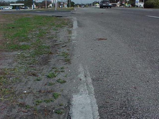
18 NOTES: 1) All pavement characteristics are to be rated as last constructed. (Rigid pavement overlaid with asphalt should be rated under the flexible pavement characteristic). 2) When a railroad crossing falls within the sample point, the following shall apply: The area to rate shall be 3 feet outside the rails of a railroad crossing. Do not rate any area between the rails. 3) In non-curb and gutter sections, all paved areas adjacent to the travel way are evaluated as paved shoulders. For MRP purposes do not rate tapers on paved shoulders. Within curb and gutter sections, all pavement is evaluated as roadway pavement. This includes bus turnouts. Edge widening less than 2 feet in width from the travel lane edge does not meet desired conditions for paved shoulders unless specified in the Department s Straight-line Diagrams. The paved area to the right in this photo is a bus turnout. The pavement in a bus turnout should be evaluated as roadway pavement. This edge widening is less than 2 feet wide therefore, does not meet MRP standards for paved shoulders (unless specified in the Straight-line Diagrams). 14


19 Asphalt bus turnout on rural roadway. This should be rated as roadway pavement, also rate for edge raveling. (Note: Rate only the edge of pavement parallel to the travel lanes for raveling) Rate bike path within the curb & gutter as roadway pavement. 15

20 FLEXIBLE ROADWAY FLEXIBLE POTHOLE: No defect is greater than 1/2 square foot in area and no single measurement 1-1/2 inches or greater in depth. No pervious base is exposed in any hole. Flexible Pothole Potholes are normally bowl-shaped holes in the pavement that usually form in low areas, such as wheel paths and utility trenches. They are caused by pavement weaknesses, which may result from poor quality materials, thin pavement surface, poor drainage on the pavement surface or within the base, or a loss of load support by either the base or sub grade. Evaluation: Measure the size of the pothole. To measure the size of a pothole, place a straightedge across the defective area and determine if the defective area is deeper than that listed in the standard. To determine the area of a defect, measure the area as a square or rectangle. Use of a straightedge and a marker to outline the area may be helpful. In a non-curb and gutter section, do not rate the first 4 inches from the actual edge of pavement for pothole criteria (see edge raveling). Flexible pothole does not meet MRP standards when any of the following exist: 1) If BOTH depth and area are greater than the standard limits. 2) If pervious base is exposed in any hole. Measure the area and the depth of the pothole. 16
21 FLEXIBLE EDGE RAVELING: 90% of the total roadway edge is free of raveling. No continuous section of edge raveling 4 inches or wider exceeds 25 feet in length. Flexible Edge Raveling Edge raveling is the progressive separation of aggregate particles in a pavement from the surface downward or from the edges inward. Evaluation: Determine if edge raveling exists within the sample by reviewing the edge of pavement. If the pavement edge is missing or separated 4 inches or more from the edge of pavement, then edge raveling exists. Measure the length of the edge raveling that is 4 inches or wider. Two lane roadway samples with no paved shoulders can have a maximum pavement edge of 1,056 feet (528 ft. length X 2 roadway edges). A divided roadway with no paved shoulders can have a maximum pavement edge of 2,112 feet (528 ft. length X 4 roadway edges). Measurements are made from the actual edge of pavement. At least 90% of the total roadway edge should be free of raveling or this characteristic does not meet the desired maintenance conditions. Roadway edge raveling should not be evaluated when paved shoulders, any type of curb, curb and gutter, or any permanent construction is installed that will protect the pavement edge. Flexible edge raveling does not meet MRP standards when any of the following exist: 1) The roadway contains edge raveling at least 4 inches wide and 25 continuous feet in length. 2) More than 10% of the total roadway edge has edge raveling. ROADWAY EDGE RAVELING TABLE No of Pavement Edges Total Length (ft) 90% (ft) 10% (ft)


22 A roadway without paved shoulders would be rated for edge ravel. Rate edge raveling at crossovers where pavement without paved shoulders ties into paved shoulders. 18


23 FLEXIBLE SHOVING: The shoved area does not exceed a cumulative 25 square feet. Flexible Shoving - Flexible shoving is the lateral or longitudinal movement of flexible roadway surface most often caused by the acceleration or deceleration of vehicular traffic. Severe movement will result in cracking or breaking of the riding surface exposing the underlying roadway course or the base material. Evaluation: Measure the length and width of the shoved area. If more than 25 square feet of roadway, in a sample, is displaced by pushing or shoving, then this characteristic does not meet the desired maintenance condition. Base failure and rutting are not to be considered as shoving but can cause shoving. Flexible Shoving does not meet MRP standards when any of the following exist: 1) More than 25 cumulative square feet of roadway, in a sample, is displaced by pushing or shoving. These are pictures of shoving. Measure the length and width to determine the shoving area. If the shoving area is more than 25 cumulative square feet, then this would not meet conditions for shoving. 19


24 FLEXIBLE DEPRESSION/BUMP: No deviation exceeds more than 1/2 inch for any area greater than 1 square foot. No single measurement shall exceed 2 inches. Flexible Depression/Bump - A pavement depression or bump is a deviation from design grade. It may be an area close to or caused by an inlet, manhole or underground utility installation. Evaluation: To determine if there is a depression or bump within the sample area, survey the roadway pavement. Many depressions or bumps are located near inlets, manholes or underground utility installations. Vehicles traversing the sample can give an indication if a depression or bump is present. Include parking lanes and bus turnouts in the evaluation. If there is an indication of a depression or bump within the sample area, measure the area. If the area is greater than the standard, then measure the height or depth of the depression or bump. If the height or depth and area are greater than the standard, then this characteristic does not meet desired maintenance conditions. Flexible depression/bump does not meet MRP standards when any of the following exist: 1) A deviation from design grade greater than 1/2 inch for any area greater than 1 square foot. 2) Concrete and/or asphalt spills which exceed 1/2 inch and 1 square foot. 3) Any single measurement of a depression or bump exceeding 2 inches. Concrete spill, rate as a bump. Depression at a water valve in pavement. 20


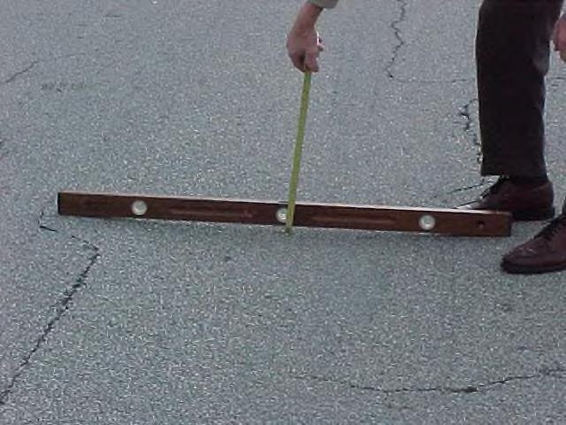
25 Depression next to a curb inlet. Measuring the depth of a depression. Measuring the depth of a depression. Measuring the depth of a depression. 21

26 FLEXIBLE PAVED SHOULDER/TURNOUT NOTE: Many roadways have combinations of paved and unpaved shoulder widths. The measurements for evaluation of the PAVED SHOULDER characteristic are different than those for ROADWAY. The methods for measuring or evaluating will be the same as for ROADWAY. Paved shoulder evaluation includes edge widening. Edge widening less than 2 feet in width from the travel lane edge does not meet desired conditions for paved shoulders unless noted on the Department s Straight-line Diagrams. FLEXIBLE PAVED SHOULDER/TURNOUT: Rate flexible paved shoulder for pothole, edge raveling and depression/bump. Rate flexible turnout for pothole only. FLEXIBLE PAVED SHOULDER: Pothole No defect is greater than 1/2 square foot in area and no single measurement 1-1/2 inches or greater in depth. No pervious base is exposed in any hole. Flexible pothole does not meet MRP standards when any of the following exist: 1) If BOTH depth and area are in the standard limits or greater. 2) If pervious base is exposed in any pothole. NOTE: For MRP purpose, evaluate all asphalt from adjacent to the paved shoulder to the face of guardrail (when present) as part of the paved shoulder. Pothole in paved shoulder. Measurements should be taken to determine if this meets MRP Standards. For MRP purpose, evaluate asphalt from edge of travel lane to face of guardrail as paved shoulder. 22
 If more than 25% of the shoulder edge contains edge raveling.")
27 Edge Raveling 75% of the total shoulder edge is free of raveling. No continuous section of edge raveling 4 inches or wider exceeds 50 feet in length. Edge raveling does not meet MRP standards when any of the following exist: 1) If more than 25% of the shoulder edge contains edge raveling. 2) If there are more than 50 continuous feet of edge raveling 4 inches or wider. Edge raveling on paved shoulder. Measurements should be taken to determine if this meets MRP Standards. PAVED SHOULDER EDGE RAVELING TABLE No. of Pavement Edges Total Length (ft.) 75% (ft.) 25% (ft.)
 A deviation from design grade greater than 1 inch for any area greater than 1 square foot.")
28 Depression/Bump No deviation exceeds 1 inch for any area greater than 1 square foot. No single measurement shall exceed 3 inches. Depression/Bump does not meet MRP standards when any of the following exist: 1) A deviation from design grade greater than 1 inch for any area greater than 1 square foot. 2) Concrete and/or asphalt spills which exceed 1 inch and 1 square foot. 3) Any single measurement of a depression or bump exceeding 3 inches. NOTE: The encroachment of soil build-up on paved shoulders should be rated under the UNPAVED SHOULDER characteristic. Measure deviations on paved shoulders to determine if they meet MRP standards. 24
 should extend out 5 feet from the edge of the pavement or to the limits of paved shoulders.")
29 FLEXIBLE TURNOUT: Pothole No defect is greater than 1/2 square foot in area and no single measurement 1-1/2 inches or greater in depth. No pervious base is exposed in any hole. Flexible Turnout Paved aprons in highway section turnouts (no curb and gutter) should extend out 5 feet from the edge of the pavement or to the limits of paved shoulders. Turnouts in paved shoulder sections should be rated as paved shoulders. If there is no requirement for a paved apron as specified in the Design Standards, rural turnout construction (less than 20 trips/day), rate as non-paved shoulder. The area outside the apron on an unpaved turnout should be rated as shoulder and front slope, if present. Paved aprons in curb and gutter section turnouts may be of rigid or flexible construction. Evaluation of urban flared turnouts shall include the area from the back of curb to the front end of the sidewalk as turnout. DO NOT evaluate dedicated streets and roads (normally should have a street sign) for paved aprons. Unpaved turnouts in curb and gutter sections shall be rated as curb and sidewalk edging. Flexible turnout does not meet MRP standards when any of the following exist: 1) If BOTH depth and area are greater than the standard limits. 2) Any exposed pervious base. This is an example of a turnout in a paved shoulder section. This should be rated as paved shoulder only. 25
30 26
31 27

32 RIGID ROADWAY NOTE: The methodology used for evaluating potholes and depression/bump will be the same for both flexible and rigid pavements. This picture of rigid pavement with an asphalt utility/expansion joint/patch. This area should be rated for rigid and flexible pavement. Pavement characteristics should be rated as last constructed. 28


33 RIGID POTHOLE: No defect is greater than 1/2 square foot in area and no single measurement 1-1/2 inches or greater in depth. No pervious base is exposed in any hole. Rigid Pothole Potholes are normally bowl-shaped holes in the pavement that usually form in low areas, such as wheel paths and utility trenches. They are caused by pavement weaknesses, which may result from poor quality materials, thin pavement surface, poor drainage on the pavement surface or within the base, or a loss of load support by either the base or sub grade. Evaluation: Measure the size of the pothole. Place a straightedge across the defective area and determine if any single measurement of the defective area is 1½ inches or deeper. To determine the area of a defect, measure the area as a square or rectangle. Use of a straightedge and a marker to outline the area may be helpful. Rigid pothole does not meet MRP standards when any of the following exist: 1) If BOTH depth and area are greater than the standard limits 2) If pervious base is exposed in any hole. These are pictures of defects in rigid pavement. Calculate the area to determine if it is greater than 1/2 square foot and measure the depth of the defect. If BOTH depth and area are greater than the standard limits the areas do not meet MRP standards. 29
34 RIGID DEPRESSION/ BUMP: No deviation exceeds 1/2 inch for any area greater than 1 square foot. No single measurement shall exceed 2 inches. Rigid Depression/Bump A pavement depression or bump is a deviation from design grade. It may be an area close to or caused by an inlet, manhole or underground utility installation. This characteristic also includes parking lanes. Evaluation: To measure the size of a depression or bump, first measure the area. If the area of the depressed or elevated area is less than 1 square foot, then no further measurements are necessary because it is not rated as a depression /bump unless a single measurement exceeds 2 inches. If the area is greater than 1 square foot, then measure the depression by putting a straightedge across the depression and measuring the distances from the straightedge to the lowest area in the depression. If this distance exceeds 1/2 inch, then the area does not meet desired maintenance conditions. A Rigid Depression/Bump does not meet MRP standards when any of the following exist: 1) A depression more than 1/2 inch exists with an area greater than 1 square foot. 2) A bump 1/2 inch or greater exists with an area greater than 1 square foot. 3) Any depression or bump greater than 2 inches. 30


35 RIGID JOINT/ CRACKING: RIGID JOINT: 85% of the length of transverse and longitudinal joint material appears to function as intended. Rigid Joints - Joints are placed in rigid pavement to control cracking and to allow for year-round contraction and expansion. Joints should be sealed to restrict the intrusion of water and incompressible into the joint. Sealed joints extend the life of the rigid pavement. Evaluation: To determine if this characteristic meets MRP standards, you must first calculate the total length of transverse and longitudinal joints in the sample. This can be accomplished by computation or actual measurement. Transverse joints are generally about 20 feet apart but an on-site verification should be done. Count the number of transverse joints and multiply by the width of the road. Count the number of longitudinal joints and multiply by the length of the joints. To obtain the total length of joint material, add the length of transverse and longitudinal joints together. Generally, it is easier to multiply the total joint length to be evaluated by 0.15 (15%) to determine what length is allowed below the desired maintenance condition and then measure those joints that do not function as intended. A cumulative length greater than 15% of the total does not meet the desired maintenance condition. On multi-lane divided sections, with paved shoulders, BOTH the paved median shoulder and paved outside shoulder joints are to be evaluated. DO NOT rate the longitudinal joint between the rigid pavement and asphalt shoulder if it was never sealed. Rigid Joints do not meet MRP standards when the following exist: 1) More than 15% of the total transverse and longitudinal joint length is missing. Transverse joints Longitudinal joint This picture shows two traverse joints and a slab that has two unsealed cracks. Do not rate the longitudinal joint between the rigid pavement and the asphalt shoulder if it was never sealed. 31


36 RIGID CRACKING: 90% of the roadway slabs have no unsealed cracks wider than 1/8 inch. Rigid Cracking A slab is defined as that area within the existing control joints. Do not include the control joints in the evaluation. Evaluation: Determine the total number of slabs within the evaluation area. Then determine the number of slabs that have unsealed cracks wider than 1/8 inch. Divide the number of slabs with unsealed cracks wider than 1/8 inch by the total number of slabs within the evaluation area to determine the percentage of slabs with unsealed cracks wider than 1/8 inch. If this percentage is more than 10%, then this characteristic does not meet desired conditions. Rigid Cracking does not meet MRP standards when the following exist: 1) More than 10% of the slabs have unsealed cracks greater than 1/8 inch. These pictures show an unsealed crack wider than 1/8 inch in rigid pavement. 32
37 RIGID PAVED SHOULDER/TURNOUT NOTE: Rate rigid shoulder for pothole, depression/bump and joint/cracking. Rate rigid turnout for potholes and cracking only. RIGID PAVED SHOULDER: Rate rigid paved shoulder for pothole, depression/bump and joint/cracking. Pothole: No defect is greater than 1/2 square foot in area, and no single measurement 1-1/2 inches or greater in depth. No pervious base is exposed in any hole. Rigid Paved Shoulder does not meet MRP standards for Pothole when any of the following exist: 1) If pervious base is exposed in any hole. 2) If BOTH depth and area are greater than the standard limits. Depression/Bump: No deviation exceeds 1 inch for any area greater than 1 square foot. No single measurement shall exceed 3 inches. Rigid Paved Shoulder does not meet MRP standards for Depression/Bump when any of the following exist: 1) A deviation from design grade greater than 1 inch for any area greater than 1 square foot. 2) A single measurement greater than 3 inches above or below the design grade. Joint: 75% of the joints appear to function as intended by restricting the intrusion of water and incompressible. Rigid Paved Shoulder does not meet MRP standards for Joints when any of the following exist: 1) More than 25% of the joints do not function as intended. Cracking: 80% of the paved shoulder cumulative areas have no unsealed cracks wider than 3/4 inch. Rigid Paved Shoulder does not meet MRP standards for Cracking when any of the following exist: 1) More than 20% of the slabs have unsealed cracks greater than 3/4 inch. 33
 If BOTH depth and area are greater than the standard limits.")
38 RIGID TURNOUT: Pothole: Rate rigid paved turnout for potholes and cracking only. No defect is greater than 1/2 square foot in area and no single measurement 1-1/2 inches or greater in depth. No pervious base is exposed in any hole. Rigid Turnout does not meet MRP standards for Pothole when any of the following exist: 1) If BOTH depth and area are greater than the standard limits. 2) If pervious base is exposed in any hole. Cracking: 80% of rigid paved turnout cumulative area has no unsealed cracks wider than 3/4 inch. Rigid Turnout does not meet MRP standards for Cracking when any of the following exist: 1) More than 20% of the cumulative turnout area has unsealed cracks wider than 3/4 inch. These are urban flared turnouts. The area from the back of curb to the front of the sidewalk is to be rated as turnout. 34
39 FLORIDA DEPARTMENT OF TRANSPORTATION MAINTENANCE RATING PROGRAM STANDARDS ROADSIDE THE FOLLOWING CHARACTERISTICS MEET THE DESIRED MAINTENANCE CONDITIONS WHEN: UNPAVED SHOULDER: No deviation exists across the shoulder width greater than 5 inches above or below the design template. No shoulder build-up exceeds 2 inches anywhere across the design template for a continuous 25 feet. No shoulder drop-off exceeds 3 inches deep within 1 foot of the pavement edge for a continuous 25 feet. No encroachment 12 inches or greater of sand, soil, grasses, or debris on to the outside paved shoulder for 25 continuous feet. No washboard areas exist having a total differential greater than 5 inches from the low spot to the high spot. FRONT SLOPE: No deviations exist greater than 6 inches in depth or height. SLOPE PAVEMENT: No single area of missing, settled or misaligned areas exist greater than 10 square feet. SIDEWALK: 99.5% of sidewalk area is free of vertical misalignments greater than 1/4 inch or horizontal cracks greater than 3/4 inch, and no visible hazards. FENCE: No unrestrained entry is allowed. 35
40 ROADSIDE UNPAVED SHOULDER: No deviation exists across the shoulder width greater than 5 inches above or below the design template. No shoulder build-up exceeds 2 inches across the design template for a continuous 25 feet. No shoulder drop-off exceeds 3 inches deep within 1 foot of the pavement edge for a continuous 25 feet. No encroachment 12 inches or greater of sand, soil, grasses, or debris on to the outside paved shoulder for 25 continuous feet. No washboard areas exist having a total differential greater than 5 inches from the low spot to the high spot. Unpaved Shoulder - Generally, shoulders are designed to drop at 3/4 inch per foot from the pavement edge except in super elevated curves. Evaluation: To measure a shoulder drop-off, place a straightedge on the pavement and measure down. If the straight-line diagrams (SLD s) do not indicate an unpaved shoulder in conjunction with a paved shoulder, the first two feet adjacent to the paved shoulder should be rated as unpaved shoulder. This applies to the inside and outside paved shoulder. Unpaved shoulder does not meet desired maintenance conditions when any of the following exist: 1) Any shoulder drop-off, within one foot of the pavement edge, exceeds 3 inches in depth for 25 continuous feet. 2) Any deviation of shoulder elevation, including the radius at paved turnouts, is greater than 5 inches above or below the design template. 3) Any shoulder build-up exceeds 2 inches across the design template for 25 continuous feet. 4) Any encroachment 12 inches or greater of sand, soil, grasses, or debris on to the outside paved shoulder for 25 continuous feet. 5) Any washboard areas having a total differential greater than 5 inches from the low spot to the high spot. NOTE: Utility strips will be evaluated using the CURB/SIDEWALK EDGING characteristic Miscellaneous asphalt outside the paved shoulder limits should be rated as un-paved shoulder and/or front slope. 36
41 SHOULDER DIAGRAM AND CHART ¼ in. per ft. Y Back Slope Front Ditch Bottom Shoulder Width (feet) X Drop from Edge of Pavement (inches) Y NOTE: A straight edge placed on the pavement can be used to measure drop-offs within the first 1 foot of pavement edge. A level should be used for other measurements across the soil shoulder width. 37


42 Shoulder drop-off. Paved shoulder with soil shoulder. See SLD for dimensions. Drop-off behind curb. Since this road has curb & gutter this would be evaluated under curb & sidewalk edging. High shoulder 2 inches or more for 25 continuous feet does not meet MRP Standards. Shoulder drop off greater than 5 inches does not meet MRP Standards. This is an example of a soil shoulder that meets MRP standards. 38 Encroachment of soil and grasses on to the outside paved shoulder. Measurements should be taken to determine if this meets conditions. standards.


43 These pictures are examples of a roadway with a paved shoulder. If the SLD s do not indicate an unpaved shoulder in conjunction with a paved shoulder, the first two feet adjacent to the paved shoulder should be rated as unpaved shoulder. 25 feet 12 inches The asphalt is broken with a deviation greater than 5 inches and would not meet desired maintenance conditions for unpaved shoulder Measure encroachment on to the paved shoulder, if it is one foot or greater for more than 25 continuous feet then it would not meet desired maintenance conditions. 39

44 This is an example of a straight line diagram (SLD) that shows paved shoulders and lawn shoulders. In this case FLEXIBLE PAVED SHOULDER/TURNOUT and UNPAVED SHOULDER characteristic should be rated. 40


45 FRONT SLOPE: No deviations exist greater than 6 inches in depth or height. Front slope Front slopes provide a gradual and contoured transition from the shoulder edge to the roadside ditch or toe of slope in a fill section. Evaluation Survey the sample point for deviations which may include ruts, washouts and/or buildups. Any deviation greater than 6 inches does not meet desired maintenance conditions. When rating front slope washouts in a turnout area, project the roadway toe of front slope across the turnout. Do not rate beyond the toe of slope for washouts in a turnout. Front slopes are evaluated from the shoulder edge to the roadside ditch bottom, to edge of slope in a fill section or to the limits of the rightof-way. Front slope does not meet MRP standards when any of the following exist: 1) Any deviation greater than 6 inches in depth or height. These are examples of front slope deviations greater than 6 inches. These conditions do not meet MRP standards. 41


46 This is a washout in front of a headwall greater than 6 inches in depth. This would not meet MRP maintenance standards. The asphalt under the guardrail has washed out. The guardrail meets desired maintenance standards, however, unpaved shoulder or front slope would not meet desired MRP standards. 42
 greater than 10 square feet does not meet desired maintenance conditions")
 There is missing slope pavement greater than 10 square feet.")
47 SLOPE PAVEMENT: No single area of missing, settled or misaligned areas exist greater than 10 square feet. Slope Pavement Any single area of missing, settled or misaligned area of paved slope (includes any paved slope treatment) greater than 10 square feet does not meet desired maintenance conditions (This includes sand cement riprap). Evaluation: Review the existing slope pavement within the sample area. Measure any missing, settled or misaligned areas. Slope Pavement does not meet MRP standards when any of the following exist: 1) There is missing slope pavement greater than 10 square feet. 2) There is settled slope pavement greater than 10 square feet. 3) There is misaligned slope pavement greater than 10 square feet. This is an example of rip-rap slope pavement. This is an example of concrete slope pavement. 43
48 SIDEWALK: 99.5% of sidewalk area is free of vertical misalignments greater than 1/4 inch, horizontal cracks greater than 3/4 inch, or spalled areas greater than ½ inch in depth, and no visible hazards. Sidewalk Sidewalk is constructed of various materials and is subject to misalignments caused by growing tree roots, settling or deterioration. This measurement includes the normal sidewalk joint and the sidewalk to curb joint. Sidewalk should be projected across an urban flared paved turnout and that area evaluated as sidewalk. Any bike path located outside the roadway pavement area will be evaluated as sidewalk. Paved utility strips are evaluated as sidewalk if they are intended to be used as sidewalk. Sidewalk shall not be evaluated across dedicated streets. Spalled areas greater than 1/2 inch in depth do not meet desired conditions. Uniform deviation from original grade that has vertical misalignments or cracks greater than 1/4 inch do not meet desired maintenance conditions. Changes in level up to 1/2 inch may be beveled with a slope that complies with Fig. 7. For purposes of evaluating this characteristic, one linear foot of misalignment or cracking not meeting desired conditions equals one square foot of sidewalk area. Do not exceed one linear foot of cracking in a one square foot area. Unsealed joints greater than 3/4 inch do not meet desired maintenance conditions. For MRP purposes, no rigid objects protruding from concrete greater than ¼ inch in height, or any single misalignment, or deviations greater than 1½ inches. For MRP purposes if an entire slab is missing in a continuous section of sidewalk, multiply the length of the missing section by the width to get the area missing. For example, if a 5 ft. section of sidewalk 5 ft. wide is missing the area would be 25 sq. ft. If the area missing combined with the total area of cracking is greater than that allowed for the standard then sidewalk does not meet MRP standards. Evaluation: Measure the length of sidewalk and multiply by the width of sidewalk to determine the total area. Then multiply the total area by to determine the maximum area that can have vertical misalignments greater than 1/4 inch or horizontal cracks greater than 3/4 inch. Measure any rigid objects protruding from concrete sidewalk greater than ¼ inch in height, also measure for single misalignment, or deviations greater than 1½ inches. SIDEWALK TABLE Width Area 99.5% (ft.) (sq.ft) (sq.ft) Total Length (ft) 0.5% (sq.ft) Sidewalk does not meet MRP standards when the following exist: 1) More than 0.5% of the sidewalk area has vertical misalignments greater than 1/4 inch, horizontal cracks greater than 3/4 inch, or spalled areas greater than ½ inch in depth. 2) Any rigid objects protruding from concrete greater than ¼ inch in height, or any single misalignment, or deviations greater than 1½ inches. 44


49 Sidewalk cracking. Measure each horizontal crack greater than 3/4 inch wide. For MRP purposes, each linear foot of horizontal crack greater than 3/4 inch equals 1 sq. ft. of crack area. Vertical misalignments greater than 1/4 inch equals 1 sq. ft. of crack area. Sidewalk cracking. Measure each horizontal crack greater than 3/4 inch wide. For MRP purposes, each linear foot of horizontal crack greater than 3/4 inch equals 1 sq. ft. of crack area. Any single vertical misalignment measured greater than 1 1/2 inch would not meet desired maintenance conditions. These pictures are examples of utility strips that have been paved with brick and concrete. For MRP purposes these areas should be rated as sidewalk. 45


50 This is an urban flared turnout. The sidewalk should be projected across the turnout and evaluated as sidewalk. In this case turnout would not be evaluated. Rigid objects protruding from concrete greater than ¼ inch in height. 46
51 ADA Wooden sidewalks/boardwalks: All wooden/sidewalks/boardwalks within the right-of-way, maintained by the department, shall be included in the sidewalk evaluation. Evaluation: The evaluation shall include inspection of support pilings/posts, X bracing (if installed), hardware (nuts, bolts, washers, and fasteners), spindles (if installed), handrails (wood or pipe), and surface deck boards. Wood sidewalks / boardwalks do not meet MRP standards when the following exists; 1) Any significant visible signs of damage or deterioration of support piling, post. X or cross bracing. 2) Any missing hardware. 3) Handrails and supports not secure. 4) All spindles shall be in place and function as intended. 5) No missing surface deck boards, no more than 0.5% of the surface deck boards are loose, have vertical misalignments or horizontal cracks greater than ¾ inch. 6) Any rigid objects protruding from the surface greater than ¼ inch in height, or any single misalignment, or deviations greater than 1½ inches. 47


52 Wood sidewalk / boardwalk Spindles or pickets on handrail Pipe handrail Wood with pipe handrail Support piling / post with bracing. Deterioration of supports. Surface deck boards with misalignments. 48
53 FENCE: No unrestrained entry is allowed. Fence - Fences are constructed on limited access facilities and restricted areas to discourage people, animals and vehicles from entering the right-of-way at unauthorized locations. Evaluation: Inspect the fence within the sample area. Any unauthorized opening in the fence line within the Department s right-of-way that allows unrestrained access causes this characteristic not to meet the desired maintenance conditions. Unrestrained access is defined as less than 2/3 (67%) of its original height as measured from natural ground to the top of the fence fabric or any opening in the fence fabric greater than 2 square feet. Gates may be located in fenced areas. All gates should be closed and locked to prevent people, animals and vehicles from entering the right-of-way at unauthorized locations. For MRP purposes two posts in a row missing, broken, or fence fabric is not attached does not meet desired maintenance conditions. MRP defines fence post as broken when it is cracked into pieces, splintered or fractured. A broken fence post is considered missing. A minimum of one continuous strand of barb wire must be in placed at the top of the fence to meet desired maintenance conditions. Rate fence across an outfall ditch as installed. Washouts under the fence are not rated in the FENCE characteristic. If any part of the fence can be reached, then that portion of the fence should be evaluated. If after a reasonable effort, no portion of the fence can be inspected, do not rate FENCE. The coding sheet will be coded as ---. Fences are to be evaluated according to the Design Standard that the fence was installed. Fence does not meet MRP standards when any of the following exist: 1) If there is an opening in the fence greater than 1/3 of its original height as measured from the natural ground, to the top of the fence fabric. 2) If there is an opening in the fence fabric greater than 2 square feet. 3) Any open or unlocked gate in the Department owned fence within the sample point. 4) Any open space greater than 6 inches between gates or posts. 5) Two fence posts in a row are missing or broken within the sample. 6) Any two consecutive fence posts where the fabric is not attached. 7) Less than one continuous strand of barb wire is in place at the top of the fence. 49


54 Fence fabric should be attached securly to two consecutive fence post. Fence posts should be in place and functioning as intended. If two consecutive fence posts are missing or broken this would not meet MRP standards This fence has been cut and is open. This does not meet MRP standards. This fence has been damaged and is not the correct height. This does not meet MRP standards. Measure the height of the fence from natural ground to the top of the fence fabric. 50


55 Measure the height of the fence from natural ground to the top of the fence fabric. Both strands of barb wire are missing along top of fence, this would not meet desired maintenance conditions. Misaligned gates, measure opening to ensure it is not greater than 6 inch opening. 51
56 FLORIDA DEPARTMENT OF TRANSPORTATION MAINTENANCE RATING PROGRAM STANDARDS TRAFFIC SERVICES THE FOLLOWING CHARACTERISTICS MEET THE DESIRED MAINTENANCE CONDITIONS WHEN: RAISED PAVEMENT MARKERS: STRIPING: PAVEMENT SYMBOLS: GUARDRAIL: SIGNS LESS THAN OR EQUAL TO 30 SQ. FT.: SIGNS GREATER THAN 30 SQ. FT.: OBJECT MARKERS & DELINEATORS: 70% of the required markers are functional (reflective). No more than 100 feet of continuous centerline or lane line is without a reflective marker. 90% of the length and width of each line functions as intended. 70% of existing symbols function as intended. Each single run functions as intended. 95% of the signs are functioning as intended. 85% of the signs are functioning as intended. 80% of the markers are functioning as intended. LIGHTING: 90% of the total luminaries of the combined sign and highway lighting are functioning as intended. NOTE: Nighttime reflectivity checks are required for the following characteristics if day time conditions are met: Raised pavement markers (RPM s) Striping Pavement symbols Signs Object markers/delineators. Conduct nighttime reflectivity checks using low beam headlights only. Ride the same roadway in both directions to check reflectivity. The nighttime reflectivity check should be conducted when the pavement is dry. Nighttime checks are required for the lighting if day time conditions are met. Attenuators are not rated for MRP, any deficiencies observed should be reported to the maintaining agencies. 52
57 TRAFFIC SERVICES RAISED PAVEMENT MARKERS: 70% of the required markers are functional (reflective). No more than 100 feet of continuous centerline or lane line is without a reflective marker. Raised Pavement Marker Raised pavement markers are reflective white, amber or red. Some markers are designed with a reflector on one side only. Raised pavement markers are effective aids for night driving, especially on wet pavement. They are required on ALL FDOT highways to delineate centerline, some curbs, traffic islands and for the transition of roadway or lane width changes. Evaluation: Daytime Check to make sure the correct number of markers are installed. Count all the markers that should be present. Then count the number of missing markers. Determine the percentage of markers missing by dividing the number missing by the total number that should be present. Nighttime Raised Pavement Marker shall be visible and reflective at night with low beam headlights. Determine if the markers are reflective at night for a distance of 528 feet. Two lane roadways shall be evaluated from both directions. No more than 100 feet of continuous centerline or lane line should be without a reflective marker. If RPM s are required on edge lines, they should be rated. At least 70% of the required markers should be functional (reflective) at a distance of 528 feet. Refer to the Design Standards for Raised Pavement Marker placement. Designed breaks in pavement lines (crossovers, intersections) shall not be included in the 100 feet. Raised Pavement Markers do not meet MRP standards when any of the following exist: 1) If more than 30% of the required raised pavement markers are missing. 2) If more than 30% of the required markers are not functional (reflective) at a distance of 528 feet. 3) If more than 100 continuous feet of centerline or lane line is without a reflective marker. 4) If the raised pavement markers are installed incorrectly (Index 17352). 53
58 STRIPING: 90% of the length and width of each line is reflective and functions as intended. Striping Pavement striping is a 6 inch wide centerline; skip line or edge line. Evaluation: Daylight and nighttime inspections shall be done. Each line is evaluated independently. Solid lines - Determine the length and width of each solid line in the sample point. A minimum of 5.4 inches of each line width should be present, visible and reflective at night with low beam headlights. Determine if the lines are reflective at night for a distance of 160 feet. Due to changes in design standards, striping may have been installed at certain locations on some roadways where no striping is installed at similar locations on other roadways. Do not evaluate striping at locations where it has not been installed. Skip lines Determine the length and width of each skip line in the sample point. A minimum of 5.4 inches of each line width should be present, visible and reflective at night with low beam headlights. Only evaluate the stripe and not the skip. Contrast lines - Black lines are used for contrast only and should not be evaluated for reflectivity. They are rated for length and width only, if present and maintained. Refer to Design Standards for Interchange markings and special marking areas. Striping does not meet MRP standards when any of the following exist: 1) If more that 10% of the length of any line is less than 5.4 inches wide during daylight inspection. 2) If more than 10 % of the length and width of any line is not visible for a distance of 160 feet at night. 3) If more than 10% of the length of any line is missing. 4) If more than 10% of the length of any line is covered by soil, grass, or debris, staining, or skid marks. 54
59 55


60 Striping on a typical four lane divided highway. These pictures show painted yellow and white edge lines installed on a newly constructed or resurfaced roadway. Evaluate according to the striping characteristic. 56


61 Worn out edge line does not meet MRP standards. Worn out edge line does not meet MRP standards Worn out striping in an urban area does not meet MRP standards. Edge line obscured by soil or other debris does not meet MRP standards 57


62 Edge line does not meet MRP standards Edge line obscured by grass does not meet MRP standards. Existing white edge line on an urban curb & gutter section. This meets MRP standards. No white edge line on this urban curb & gutter section. This also meets MRP standards. 58


 If more than 30% of cumulative symbol area is not reflective for a distance of 160 feet using low beam headlights during nighttime observation.")
63 PAVEMENT SYMBOL: 70% of existing symbols function as intended. Pavement Symbol - Pavement symbols are used to communicate certain meanings at specific locations. Included in this characteristic are gore area markings, shoulder markings, word and symbol markings, stop bars, all crosswalk lines within the R/W, parking space markings (does not include edge lines that delineate parking), curb markings, painted medians, radius markings, turning guidelines and others. Evaluation: Determine the total square footage of all symbols within the sample point. Symbols that appear to be abandoned should be verified as such with the area engineer and not be evaluated if determined to be abandoned. Curb markings and crosswalks on connecting side streets are not to be evaluated for nighttime reflectivity. The Design Standards or the MMS Handbook can be referenced to determine the square footage of symbols. Pavement Symbols do not meet MRP standards when any of the following exist: 1) If more than 30% of the cumulative symbol area is not functioning as intended during daylight observation. 2) If more than 30% of cumulative symbol area is not reflective for a distance of 160 feet using low beam headlights during nighttime observation. 3) If symbols are not installed according to the Design Standards. Pavement symbols in good condition, meets MRP standards. Pavement symbols in good condition, meets MRP standards. These pictures are examples of worn out symbols. If more than 30% of the cumulative symbol area is not functioning as intended then this would not meet MRP standards. 59


64 Worn and faded pavement symbol, may not meet MRP standards. These skip lines are an example of radius markings. Interstate Exit marking symbol. Painted curb markings are rated as symbols. Do not rate curb markings for nighttime reflectivity. Symbols Perpendicular lines marking parking spaces are rated as symbols. This is an example of a crosswalk symbol. 60
65 GUARDRAIL: Each single run functions as intended. Guardrail - Guardrail is installed to guide a vehicle away from various hazards in and adjacent to the travel way and, in most cases, where fill slopes exceed 3:1. This characteristic also includes evaluation of cable rail and handrail. Refer to the Design Standards. The function of the bearing plate is to transfer load from the cable to the end anchorage. Bearing plates shall be galvanized, properly oriented, and restrained from turning by acceptable method. The cable on the end anchorage assembly shall be taut with no more than one (1) inch of movement in the cable. Evaluation: Determine the general condition of the guardrail. Check the guardrail height. Check for damaged rail, missing or damaged posts or blocks, connecting hardware and end sections. Check to make sure guardrail is lapped correctly. If there is less than 25 feet of guardrail in a sample, then 50% or more of the guardrail must meet the height requirement for this sample point to meet maintenance conditions. All other guardrail criteria shall be rated no matter what the length. Consideration should be given to what Design Standards were used during original construction of guardrail. A previous minor collision may not prevent a guardrail system from functioning as designed and would not cause failure. Installations may vary from roadway to roadway because of design standard changes and should be evaluated using the appropriate design standard. For MRP purposes do not rate miscellaneous asphalt under guardrail as part of the guardrail. If the miscellaneous asphalt under the guardrail has washed out it should be evaluated as either unpaved shoulder or front slope. Each single run of guardrail does not meet MRP standards when any of the following exist: 1) Any missing posts, offset blocks, panels or connection hardware. 2) Nuts threaded more than 1 inch to the anchor plate on end treatment cables and anchor rods (measurements should be checked with end treatment cable taut). 3) Any section that is 3 inches above or 1 inch below the desired elevation for 25 continuous feet. 4) The backup plate does not fit snugly behind the rail. There should be some point of contact. 5) The bearing plate is not secured to prevent rotation 6) End anchorage cable is not drawn taut; with more than 1 inch deflection 7) Damaged end sections. 8) The rail has been penetrated. 9) More than 10% of the guardrail blocks are twisted. 10) More than 10% of the wooden posts or blocks are rotten or deteriorated. 11) Any panel lapped incorrectly. 61


66 Buried end guardrail section. Guardrail shall be evaluated according to the index it was installed under. This may meet MRP standards. This guardrail section is low and should be measured to determine if it meets MRP standards. This guardrail section may not meet MRP standards, because the height above the ground is incorrect. This is a rotten and deteriorated guardrail offset block. It does not meet MRP standards if more than 10% of the blocks are rotten and deteriorated. This guardrail section has been penetrated due to a crash. This does not meet MRP standards. 62 Penetrated guardrail does not meet MRP standards.


67 This end section has been hit and does not meet MRP standards. This damaged end section does not meet MRP standards. The bearing plate must be secured to prevent rotation Guardrail offset blocks are not aligned properly. This condition does not meet MRP standards if more than 10% are twisted. A guardrail block is considered twisted if there is a gap between the top edge of the block and the guardrail. This guardrail has been damaged by a crash. Several posts are damaged. This does not meet MRP standards. 63


68 The offset blocks in these pictures are not aligned properly. If more than 10% of the blocks in a guardrail run are twisted it would not meet MRP standards. This guardrail section has several problems. The offset block is deteriorated and the rail is lapped incorrectly. This does not meet MRP standards. This guardrail section is lapped incorrectly. If hit by a vehicle, the rail would not function as designed. This does not meet MRP standards. This guardrail has been hit by a vehicle. The posts have been knocked out of alignment and may not function as designed. This guardrail does not meet MRP standards. This guardrail has been hit and several posts are missing. This guardrail does not meet MRP standards. 64


69 This guardrail has minor damage to the rail and a missing offset block. This would not meet MRP standards. This is an approach end guardrail end section. Check to make sure all connecting hardware is in place. The asphalt under the guardrail has washed out. The guardrail meets desired maintenance conditions, however, unpaved shoulder or front slope would not meet MRP standards. Damaged guardrail end section. This site does not meet MRP standards. 65


 Loose cable, incorrect weave or installation. 3) Damaged end sections.")

70 Cable Rail Cable Rail is installed to guide a vehicle away from various hazards in medians and adjacent to the travel way. Evaluation: Determine the general condition of the cable rail. Check the cable rail to ensure the cables are tensioned and weaved correctly (brifen). Check for damage cable, missing hardware, or damaged posts, and end treatment. Each single run of cable rail does not meet MRP standards when any of the following exist: 1) Any missing posts, cables or connection hardware. 2) Loose cable, incorrect weave or installation. 3) Damaged end sections. CASS Cable Safety System: C-shaped posts Installed in a sleeve driven into asphalt or set in concrete foundation. 3 cables in a slot at the Top of the post separated by plastic spacers. SAFENCE Post installation is similar to CASS but with 4 cables. End anchor for SAFENCE behind guardrail. BRIFFEN USA end anchor. 66


71 BRIFFEN USA Post installed in a reinforced Ring set in concrete foundation. 4 cables are placed as follows: #1 in a slot on the top of post, #2 thru 4 are interwoven between all posts on pegs located on the sides of each post. The first 15 posts adjacent to the end terminal do not have top cable / rope slot. The top cable weaves on either side of posts until the first line post with a slot. BRIFFEN USA end anchor.. GIBRALTAR Post installation similar to the CASS and SAFENCE. 3 cables are placed in molded hairpin slots or J bolts installed along the sides of the posts. 67


72 GIBRALTAR end anchor. This meets MRP standards. Damaged GIBRALTAR end anchor. This does not meet MRP standards. Loose cables on GIBRALTAR would not meet MRP standards. Misaligned cable would not meet desired maintenance conditions. 68


 One or more anchor bolts, nuts, or neoprene/resilient pads are missing on the base plate.")
 If fence is attached to the handrail, the fence must be in place and securely fastened to the handrail.")
73 Handrail Handrail is installed to protect pedestrians from drop-offs adjacent to sidewalk. Evaluation: Visually determine the general condition of the handrail within the sample. Check for bent or misaligned handrail as well as missing, cracked, or broken hardware, neoprene/resilient pads or obvious missing sections. Fence attached to the handrail must be in place and securely fastened to meet desired maintenance conditions. Each single run of handrail does not meet MRP standards when any of the following exist: 1) The handrail is not secured in place, bent or misaligned and does not function as intended. 2) One or more anchor bolts, nuts, or neoprene/resilient pads are missing on the base plate. 3) Missing, cracked, or broken hardware. 4) If fence is attached to the handrail, the fence must be in place and securely fastened to the handrail. 5) It is obvious that handrail was installed but is now missing. Handrail meets desired maintenance conditions. Missing handrail, this does not meet MRP standards. Picket railing protecting drop-off next to sidewalk. Picket railing missing steel sleeve at expansion joint. This does not meet MRP standards. 69


74 Handrail meets desired maintenance conditions. Cracked or broken hardware would not meet desired maintenance conditions. Broken welds will not meet desired maintenance conditions. 70
75 SIGNS LESS THAN OR EQUAL TO 30 SQ. FT. 95% of the signs are functioning as intended. SIGNS GREATER THAN 30 SQ. FT. 85% of the signs are functioning as intended. Signs - Signs are used to convey information to the motorist so they can travel safely and efficiently on the highway. According to the Manual on Uniform Traffic Control Devices, Placement of a traffic control device should be within the road user s view so that maximum visual acuity is provided. To aid in conveying the proper meaning, the traffic control device should be appropriately positioned with respect to the location, object, or situation to which it applies. The location and legibility of the traffic control device should be such that a road user has adequate time to make the proper response in both day and night conditions. Evaluation: Determine the number of signs within the sample point. Inspect the signs and determine the number of signs that do not meet desired MRP conditions. Divide the number of signs that meet MRP conditions by the total number of signs in the sample point. Multiply by 100 to get the percentage of signs that function as intended. If the percent is less than the standard, then the signs do not meet MRP standards. Determine what Design Standards were used during original construction and installation of signs when evaluating for MRP. Signs shielded by barrier wall or guardrail do not require breakaway support. For the purposes of evaluating individual sign installations, the following criteria shall apply: Sign Height: 1. Roads with curb and gutter: 7 feet minimum height measured from top of curb to bottom of sign (measure from sidewalk, if present). 2. Roads without curb and gutter: 5 feet minimum height measured from edge of driving lane to bottom of sign. 3. Limited access ramps: 6 feet minimum height measured from edge of driving lane to bottom of sign. 4. Limited access medians: 7 feet minimum height measured from edge of driving lane to bottom of sign. 5. Limited access roads: 7 feet minimum height measured from edge of driving lane to bottom of sign. 71

76 Sign Lateral Clearance: 1. Rural roads and limited access ramps: 12 feet minimum offset from edge of driving lane and where 12 feet cannot be met. 6 feet minimum from edge of paved shoulder to edge of sign. 2. Limited access mainline: 30 feet minimum offset from edge of mainline driving lane to edge of sign. 3. Roads with curb and gutter: 2 feet minimum offset from face of curb to edge of sign. 4. Signs behind guardrail: 2 feet minimum from the face of the rail to the edge of sign. Sign Tolerances: 1. Height Tolerance: A. 3 inch tolerance for all signs except signs over sidewalk. B. 12 inch tolerance for Type 1 and III object markers. 2. Lateral Clearance Tolerance: A. 3 inches in curb and gutter sections and behind the guardrail. B. 6 inches on limited access ramps and arterial roads. C. 12 inches on limited access mainline. The Department s Design Standards contain information on installation and placement of signs. Consideration should be given to what Design Standards were used during original construction and installation of signs. The evaluation of signs greater than 30 sq. ft. includes all over-lane signs with the exception of overhead school signs and county/city signs on signal cables. Do not rate county/city signs on signal cables. The US 17 route marker would be rated as a sign >30 sq.ft. because it is an over-lane sign. 72
77 Many cities and counties and some state and federal agencies install traffic signs and devices adjacent to or on FDOT right-of-way. Warning, Regulatory and Information signs and devices installed and maintained by FDOT are normally identified (front and back) as property of the Florida Department of Transportation and should have an installation date painted on or attached to the sign. Evaluate only FDOT signs and devices. NOTES: 1) Highway signs shall be evaluated using two characteristics: Ground signs greater than 30 square feet (including all over-lane signs). Ground signs 30 square feet or less. 2) MRP definition of a secondary sign: A secondary sign is mounted below a primary sign and its message is not related to the primary sign message. Example: A Do Not Block Intersection sign mounted with a no u-turn sign below it. 3) The height to the bottom of a secondary sign mounted below another sign may be one foot less than the appropriate height except where signs are over sidewalks (a route marking assembly consisting of a route marker with an auxiliary plate is treated as a single sign). 4) Do not rate overhead school signs or county/city signs on signal cables. 5) Do not rate logo signs. 6) Do not rate wildflower signs. 7) For purposes of these guidelines, a turn lane will be considered a driving lane. Merge, rest area, signs on islands and exit gore signs shall be evaluated according to the Design Standards. 8) If it is obvious the minimum lateral clearance cannot be met, the sign shall be considered to meet acceptable maintenance conditions. The presence of sidewalk by itself shall not be considered a reason a sign cannot meet the minimum lateral clearance. 9) A sign less than 30 square feet mounted to a sign greater than 30 square feet is evaluated as part of the sign greater than 30 square feet. 10) For MRP purposes, two post installations with round aluminum tubing less than or equal to 3-1/2 inches meets maintenance conditions. 11) Signs in the median, as outlined in the Design Standards are not evaluated for lateral clearance. 12) Do not rate slip bases for shims. 73
78 Signs do not meet desired maintenance conditions when any of the following exist: NOTE: See above for all tolerances. 1) Sign installations including panels and posts leaning more than 1 inch per foot. 2) There is missing connecting hardware, nuts and bolts. 3) Sign panels are attached to columns below a fuse cut. 4) Bottom of sign panel is installed more than 2 inches above or below the fuse cut. 5) Aluminum C clamps are used to attach a sign panel to a post. 6) Cantilever signs are not installed according to the Design Standards ) Brackets are installed improperly. 9) Sign rotation causes the sign message to become unreadable. (Note: In urban areas, NO PARKING signs may be rated 30 to 40 toward traffic). 10) Signs fail to convey the intended message due to lack of reflectivity, fading or surface accumulations. (Note: All signs shall be reflectorized or illuminated to show the same shape and color in day and night conditions). 11) Height and offset of mile markers are not installed according to the Design Standards. (Note: For MRP purposes, a height tolerance of up to 3 inches and an offset tolerance of up to 12 inches are permitted). 12) Aluminum posts greater than 3-1/2 inches in diameter are not installed on a slip base or breakaway support and are not shielded by barrier wall or guardrail. 13) A slip base or breakaway support is covered with soil. 14) A slip base or breakaway support more than 4 inches above the finished ground as measured at the center. 15) A single post installation is prohibited by the Design Standards. 16) Single post installations of a sign or sign cluster wider than 60 inches unless specifically allowed by the Design Standard Index 11860, or District Design Office. 17) A sign on a slip base is installed without a concrete footing. 18) The edge of a sign panel is installed less than 2 feet from the face of guardrail. 19) The height and lateral offset of a sign panel is not installed according to the Design Standards. 20) Damage to a sign column that compromises its function. 21) U-channel steel posts heavier than 3 pounds per foot have no breakaway support. 22) U-channel steel post with a non-standard installation where the posts is on the wrong side of breakaway. 23) Steel post support stubs protrude more than 4 inches above the ground. 74

79 Miscellaneous Sign Information This sign assembly has three (3) messages, but for MRP purposes it should be rated as one sign 75


80 Evaluate only FDOT signs. This sign has the proper label indicating when it was installed and that it is the property of FDOT. Signs should not lean more than 1 inch per foot. Measuring a sign that is leaning more than1 inch per foot. Using a 2ft. level this sign does not meet desired MRP standards. Cantilevered signs must be installed according to the design standard index Incorrect bracket installation. 76 This sign column has been damaged and does not meet desired MRP standards.


81 Slip base more than 4 inches above the ground. This does not meet MRP standards. Slip base more than 4 inches above the ground. This does not meet MRP standards. Measuring a sign post. This post is 4 inches and should be installed with a concrete foundation and breakaway assembly. This sign installation does not meet MRP standards. This sign foundation is non-standard and, if it measures more than 4 inches above the surface it does not meet MRP standards. This sign installation is leaning more than 1 inch per foot and does not meet MRP standards. Do not rate wildflower signs. 77


82 Do not rate logo signs. This breakaway device is covered and does not meet MRP standards. This steel flanged channel post is installed greater than 4 inches above the ground and does not meet MRP standards. 78


83 Fuse cut Signs installed below the fuse cut do not meet MRP standards. This steel flanged channel post is installed greater than 4 inches above the ground and is a non-standard installation does not meet MRP standards. This sign was installed using C clamps and does not meet MRP standards. 79


84 Rate cantilevered signs according to the Design Index used for installation. Rate ground mounted signs according to Design Index used for installation. This sign is in good condition but cannot be seen because of a palm tree. The sign meets MRP standards, however tree trimming would not meet MRP standards. This is a flashing school sign. This sign is not rated in MRP because it is maintained by others. 80
85 OBJECT MARKERS AND DELINEATORS: 80% of the markers are functioning as intended. Object Markers - According to the MUTCD, Object markers are used to mark obstructions within or adjacent to the roadway. Section 2C.63 Type 1 object markers are 18 inches by 18 inches. Type 2 object markers are 6 inches by 12 inches. Type 3 object markers are 12 inches by 36 inches Delineators - The MUTCD states, Delineators are particularly beneficial at locations where the alignment might be confusing or unexpected, such as at lane reduction transitions and curves. Delineators are effective guidance devices at night and during adverse weather. An important advantage of delineators in certain locations is that they remain visible when the roadway is wet or snow covered. Reflective elements for delineators shall have a minimum dimension of 3 inches. Evaluation: For MRP purposes, Type 2 Object Markers and Delineators are used to mark Department maintained objects or to delineate roadway alignment. This characteristic will include clear or amber button type reflectors installed on guardrail and barrier wall systems, button or combination button and reflective sheeting markers used at crossovers and other applications where object or guide marking is used. Delineators shall be installed with the TOP of the marker approximately 4 feet above the near pavement elevation. When used for marking objects in the roadway or 8 feet or less from the shoulder or curb, the mounting height to the bottom of the object marker should normally be 4 feet above the surface of the nearest travel lane. When used to mark the objects more than 8 feet from the shoulder or curb, the mounting height to the bottom of the object marker may be 4 feet above the ground. Except for post mounted delineators on entrance and exit ramps at interchanges all post mounted object markers and delineators installed within plus or minus 1 foot (height and lateral offset) shall meet desired maintenance conditions. Post mounted delineators on ramps (see Design Standards) shall be installed at a uniform distance from the travel lane with a tolerance of 3 inches. The height shall be uniform with a tolerance of 3 inches. Rate all post-mounted markers except those installed to prohibit unauthorized traffic movements (offtracking, median crossing, shoulder parking, etc.). Rate post-mounted delineators at major/minor intersections, if installed. The horizontal placement of post-mounted delineators at crossovers shall be 6 feet with a tolerance of plus or minus 1 foot-6 inches in accordance with Index This index shows the edge of pavement as the standard reference point. If curb and gutter is present measure from the top face of the curb. If no curb is present measure from the edge of pavement. Both day and night observations should have at least 80% of the required markers present, at the recommended height and offset and functioning as intended to meet desired maintenance conditions. 81


86 Post-mounted delineators at median crossovers and major and minor roads shall be installed according to Design Standards. Yellow delineators should be located on sides facing the crossover and green delineators should be located on sides facing away from the crossover. All connecting hardware, nuts and bolts should be installed. Delineators shall not be used as Type 2 object markers (see MUTCD). Each run of guardrail shall have reflectors according to the Design Standards. Object Markers and Delineators do not meet MRP standards when more than 20% of the following exist: 1) The horizontal placement of post-mounted delineators at crossovers are installed more than plus or minus 1 foot-6 inches from the edge of pavement or top face of curb. 2) If in the roadway or 8 feet or less from the shoulder or back of curb the marker is not installed 4 feet plus or minus 1 foot above the edge of the nearest travel lane. 3) If the bottom of the marker is not installed 4 feet plus or minus 1 foot above the ground when marking objects more than 8 feet from the shoulder or back of curb. 4) Markers are not offset 4 feet plus or minus 3 inches from the shoulder break and installed at a uniform height on interchange ramps as shown in the Design Standards. 5) Markers or delineators lean more than 1 inch per foot of post length. 6) Required markers are missing. 7) Required markers are not reflective at night. 8) Reflectors are not installed as shown in the Design Standards. 9) Color of post-mounted delineators are installed facing the wrong way. 10) Missing connecting hardware, nuts and bolts. Object markers are used to mark obstructions within or adjacent to the roadway. These object markers are marking a manhole, head- wall and U- end wall. This object marker is for fiber optic cable. It would not be rated since this is not a Department maintained object. 82


87 These post-mounted delineators would not be rated because they are being used to prohibit unauthorized traffic movements. Do not rate post-mounted markers installed to prohibit unauthorized traffic movements (off- tracking, median crossing, shoulder parking, etc.) This object marker was installed but is not needed because the headwall is behind guardrail. Since the object marker is installed, it will be rated. The object marker is installed 2 feet 6 inches from the ground to the bottom of the marker. It should be installed no less than 4 feet plus or minus 1 foot from the ground to the bottom of the marker. This marker does not meet MRP standards. These post mounted delineators are installed on a ramp according to Design Standards. This post mounted delineator is leaning more than 1 inch per foot and does not meet MRP standards. 83

.")

88 Post mounted delineators are installed according to the Design Standards. The index shows the edge of pavement as the standard reference point. If curb and gutter is present measure from the top face of. At a curb without a gutter or traffic separator, the face is the edge of pavement (picture on right). This is a rural crossover with a post mounted delineator installed. According to Design Standards the delineator should be installed 6 ft. from the edge of pavement to the delineator. MRP has a tolerance of 1 ft. 6 inches. This delineator is installed 8 ft. 6 inches from the edge of pavement. This installation does not meet MRP standards. 84


89 Paddle type, high visibility flexible delineators Type 1 (9 button) object marker 85
90 Design Standards shows the proper placement of delineator posts for median cross-overs and intersections. The horizontal placement of post-mounted delineators at crossovers shall be installed within plus or minus 1 foot 6 inches in accordance with the Design Standards. The index shows the edge of pavement as the standard reference point. 86


91 LIGHTING: 90% of the total luminaries of the combined sign and highway lights are functioning as intended. Sign Lighting - Illumination of overhead roadway signs may be by means of: a light illuminating the message through translucent material, a source that illuminates the entire face of the sign or some other source such as illuminated tubing or incandescent panels that make the message visible at night. Sign illumination that is present but not functioning should be verified as officially out of service. The area engineer can provide this information. Highway Lighting - All highway lighting Owned by the Department (DOT forces or contract maintenance) is to be included in the survey. The daytime evaluation should be for missing or damaged poles and missing or damaged luminaries. ANY electrical inspection plate, access panel cover or pull box cover that is not properly secured in place will also cause this characteristic not to meet the desired maintenance conditions. If this characteristic meets the desired daytime conditions, then a nighttime evaluation shall be made. Evaluation: Determine the total number of luminaries in the sample point. By inspection, determine the number of luminaries that do not meet desired maintenance conditions. Subtract that number from the total number of luminaries. This is the number of luminaries in the sample that meet MRP conditions. Divide this number by the total number of luminaries then multiply by 100 to get the percent of luminaries that meet desired maintenance conditions. If this percentage is equal to greater than the standard, then the point meets conditions for lighting. Lighting does not meet MRP standards when any of the following exist: 1) Any electrical inspection plate, access panel cover, or pull box cover are not properly secured in place. 2) Any exposed electrical wire. 3) If more than 10% of the total luminaries are missing, damaged, or not functioning. 4) If more than 10% of the poles are damaged or missing. Any electrical inspection plate, access panel cover or pull box cover that is not properly secured in place will cause this characteristic not to meet the desired maintenance conditions. The light poles shown above are missing the access panel cover and, therefore, do not meet MRP standards. 87


92 This would not meet conditions as properly secured. Inspection cover missing screws this would not meet conditions as properly secured. Under deck lighting Standard roadway lighting. Count the number of luminaries within the sample. Under deck lighting should be included in the evaluation of lighting. 88

93 Overhead sign lighting 89
94 FLORIDA DEPARTMENT OF TRANSPORTATION MAINTENANCE RATING PROGRAM STANDARDS DRAINAGE THE FOLLOWING CHARACTERISTICS MEET THE DESIRED MAINTENANCE CONDITIONS WHEN: SIDE/CROSS DRAIN: ROADSIDE/MEDIAN DITCH: OUTFALL DITCH: INLETS: MISC. DRAINAGE STRUCTURE: 60% of the cross-section of each pipe is free of obstructions and functions as intended. The ditch bottom elevation shall not vary from the ditch design elevation more than 1/4 of the difference between the edge of pavement elevation and the ditch design elevation. The ditch bottom elevation shall not vary from the ditch design elevation more than 1/3 of the difference between natural ground and the ditch design flow line. 85% of the opening is not obstructed. 90% of each structure functions as intended. ROADWAY SWEEPING: Material accumulation is not greater than 3/4 inch deep for more than 1 continuous foot in the traveled way or shall not exceed 1 1/2 inches in depth for more than 1 continuous foot in any gutter. NOTE: Please report any suspected Illicit Discharge found during inspections to the respective District National Pollutant Discharge Elimination System (N.P.D.E.S.) coordinator: District 1 (863) District 2 (386) District 3 (850) District 4 Broward (954) Palm Beach (561) Treasure Coast (772) District 5 (386) District 6 (305) District 7 (813) Turnpike (954)
95 DRAINAGE SIDE/CROSS DRAIN: 60% of the cross section of each pipe is free of obstructions and functions as intended. Side Drain Side drains normally occur under turnouts. Cross Drain Cross drains will normally run under a roadway(s) at a perpendicular angle and begin or end in an open roadside ditch. Drains crossing under a roadway that connect to an inlet at both ends shall not be rated. If a box culvert of any length or width falls within a sample, evaluate as normal and rate the culvert as a cross drain Evaluation: Determine the diameter of each pipe. A table is provided listing most diameters of pipe used on the FDOT s roadways and includes a measurement to assist in determining whether a pipe is obstructed more than the desired maintenance condition. The measurement will be taken at the deepest point of obstruction within the limits of the pipe including mitered ends. The percent of open area desired for SIDE/CROSS DRAIN is listed at the top of the table. Determine the pipe diameter, select the diameter in the table and move to the right along that line until under the desired percent open area and read that figure. EXAMPLE: Given an 18 inch diameter SIDE DRAIN pipe, move to the right under 60% open area and read 11 inches. Measure the open area of the pipe being surveyed. If the measurement is less than the table value 11 inches, then less than 60% of this pipe area is open and does not meet the desired maintenance condition. Grates on pipe end sections must be the correct size and in place to meet maintenance conditions. Grates that are broken will not meet maintenance conditions. In place is defined as properly seated in design cradle and cannot be unseated by normal pedestrian or vehicular traffic. For MRP evaluation purposes, a cross drain must have at least one end open within the sample point. NOTE: If the type of structure is not associated with a side/cross drain, then it is rated as a misc. drainage structure and any grating present is rated with, or under misc. drainage using the inlet characteristic for rating. If the structure is associated with a side/cross drain you would rate the grate with the side/cross drain section. If the steel grate is missing from a U type concrete end walls and the end wall is designed to cradle a steel grate, (has a channel in the concrete, or bolts are/or were present) then it would not meet conditions. The reinforced concrete slab around mitered end pipes should be in good condition. Three or more cracks in the concrete slab greater than 1/2 inch in width and 1 foot in length and/or more than 33% of the concrete structure/slab is crushed or broken does not meet maintenance conditions. NOTE: Elliptical pipe must be unobstructed more than 40% for both rise and span. 91
 The grates are not the correct type. 3) The grates are not the correct size.")
 The concrete structure around a MES has three or more cracks greater than 1/2 inch in width and 1 foot in")

96 Side/Cross Drain does not meet MRP standards when the following exist: 1) More than 40% of the cross section of the pipe is obstructed. 2) The grates are not the correct type. 3) The grates are not the correct size. 4) The grates are broken. 5) The grates are not in place. 6) The concrete structure around a MES has three or more cracks greater than 1/2 inch in width and 1 foot in length. 7) If more than 33% of the concrete structure/slab is crushed or broken around a Mitered End Section. Side drain pipe with 3 or more cracks > ½ in. wide 1 ft. in length. This does not meet MRP standards. Side drain pipe with damaged concrete. This does not meet MRP standards. 92
97 SIDE/CROSS DRAIN & MISC. DRAINAGE DESIRED % OPEN Elliptical Pipe Elliptical Pipe Round 60% 60% Pipe* 60% Rise Span Rise Span (inches) (inches) (inches) (inches) (inches) (inches) *Based on inside diameter % Rounded to nearest inch. 93


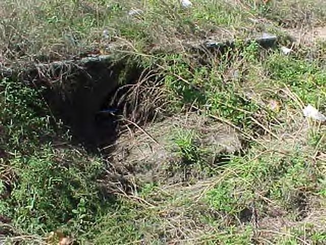
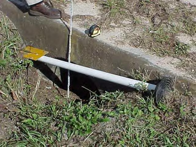
98 Side drain pipe under turnout. Side drain pipe with grates. Side drain Side drain Cross drain Cross drain 94


99 Cross drain Cross drain These two pictures show a typical side drain pipe in a roadside ditch. Determine the cross section of the pipe that is not obstructed and functions as intended. If more than 40% of the pipe cross section is obstructed or does not function as intended, then CROSS/SIDE DRAIN does not meet desired maintenance conditions. This is a side drain pipe with grates. This meets MRP standards. This is a side drain pipe with missing and damaged grates. This does not meet MRP standards. 95


100 Side drain pipe with damaged concrete. Repaired grate. Epoxy bolt. Meets MRP. Broken bolt, grate bent. Does not meet MRP Broken welds on grate. Does not meet MRP Broken bolt, grate bent. Does not meet MRP Grate meets MRP 96
101 ROADSIDE /MEDIAN DITCH: The ditch bottom elevation shall not vary from the ditch design elevation more than 1/4 of the difference between the edge of pavement elevation and the ditch design elevation. Roadside/Median Ditch (Non-Paved) In general, a standard roadside ditch (not to include ditch paving) is designed to a minimum depth below the roadway; although, there will occur special ditches or exceptions on some older roadways. A roadside ditch must have a front slope and at least a 6 inch back slope to be considered a ditch. Some roadside canals serve as roadside ditches and have a flat berm on one or both sides. For purposes of this survey, these flat areas will be considered to be front/back slopes. Generally, if the side drain or cross drain does not meet desired maintenance conditions due to siltation buildup, then the ditch will also not meet desired maintenance conditions. Evaluation: Determine if the ditch has a front slope and at least a 6 inch back slope. If it does, then you would rate the sample for roadside/median ditch. Observation of the ditches throughout the section should provide insight as to the original design of the ditches. If all ditches are the same elevation and provide proper drainage, then they are probably functioning as intended. A check of construction plans will provide an answer when a field determination is not possible. The elevation of the outside edge of roadway (not paved shoulder) will be used to determine the depth of the ditch. A surveyor s handheld level and folding rule or string line level can be used to make measurements along the sample. The construction plans or structures in and adjacent to the ditch can be used to determine the design flow line. Roadside/Median Ditch does not meet MRP standards when any of the following exist: 1) The ditch bottom elevation varies more than 1/4 of the difference between the edge of pavement elevation and the ditch design elevation. 2) There are erosions, washouts, or buildups that adversely affect the flow of water. 97

102 The bottom existing ditch elevation does not meet MRP standards. Roadside ditch with side drain pipe 98


103 OUTFALL DITCH: The ditch bottom elevation shall not vary from the ditch design elevation more than 1/3 of the difference between natural ground and the design flow line. Only those areas listed in the RCI as outfall will be evaluated. Outfall Ditch Initial observation of the ditch system, as a whole, can provide an answer as to whether actual measurements of the ditch bottom elevation shall be made. If the ditch grade appears to be higher than constructed, then actual measurements should be made. Structures included in and adjacent to the ditch or construction plans can be used to determine design flow line. After determination of designed ditch elevation, a distance from that elevation to natural ground can be calculated. If any part of the existing ditch grade is above the bottom of the calculated distance, then this characteristic does not meet the desired maintenance condition. Evaluation: Piped outfall ditches will be evaluated using the SIDE/CROSS DRAIN characteristic. The 60% of the cross sectional area shall be unobstructed criteria will apply. Paved outfall ditches will be evaluated using the criteria from miscellaneous drainage structure (rate as outfall only). Outfall Ditch does not meet MRP standards when any of the following exist: 1) The ditch bottom elevation varies more than 1/3 of the difference between natural ground and the design flow line. If the ditch bottom elevation of an outfall ditch is more than 1/3 of the difference between natural ground and the design flow line the outfall ditch does not meet MRP standards. This outfall ditch appears to meet MRP standards. 99
104 INLETS: 85% of the opening area is not obstructed. Inlets This characteristic includes all inlets and enclosed junction boxes (manholes). Inlets may be found in curbs, ditches with or without ditch paving, in valley gutters and at other locations that are designed to collect water runoff. Evaluation: Measure the opening to determine the area. When any inlet structure is unslotted then the grate is the collection area to be measured. Grates and manhole covers must be the correct size and in place to meet maintenance conditions. Grates and manhole covers that are broken will not meet conditions. In place is defined as properly seated in design cradle and cannot be unseated by normal pedestrian or vehicular traffic. Inlets with exposed steel, or surface damage 1/2 square foot or more, or any deformation of the inlet that creates a hazard, will also cause this characteristic not to meet desired conditions. The concrete apron, if present, around ditch bottom inlets should be in good condition. Concrete apron around inlets that has three (3) or more cracks greater than 1/2 inch in width and 1 foot in length or more than 33% of the concrete apron is crushed or broken does not meet desired conditions. Gutter grates or gutter cover plates on slotted curb inlets are installed as cleaning or maintenance access and are not to be considered as part of the opening area. Refer to the Design Standards to determine if the area around the inlet was designed as part of the inlet. If it was, then include it with the inlet evaluation, not as miscellaneous drainage. Inlets do not meet MRP standards when any of the following exist: 1) More than 15% of the opening area is obstructed. 2) The grate is broken. 3) Grates and manhole covers are not the correct size and are not in place. 4) Exposed steel or any deformation of the inlet that creates a hazard. 5) Surface damage 1/2 square foot or more. 6) Concrete apron with three or more cracks greater than 1/2 inch in width and 1 foot in length. 7) If more than 33% of the concrete apron is crushed or broken around inlets. 100


105 OPEN AREA Measure the opening to determine the area. 85% of the opening area must be unobstructed to meet the inlet characteristic. Grass covering inlet grate. Determine the percentage of opening area obstructed. If more than the standard, it would not meet MRP standards. Ditch bottom inlet in good condition. This meets MRP standards. 101


106 Exposed steel in this curb inlet. This does not meet MRP standards for inlets. This is an obstructed inlet grate. If the Opening is obstructed more than 85%, then it would not meet MRP standard for inlets. Soil buildup at curb inlet. Determine the percentage of opening area obstructed and compare to the standard. These inlet grates are installed backwards. This would not meet MRP standards. The inlet grate on the left is the wrong size. This would not meet MRP standards. 102


107 This inlet grate is not seated correctly in the design cradle. This does not meet MRP This manhole cover is seated correctly in the design cradle. This meets MRP standards. Inlet grate out of cradle. Does not meet MRP standards. Blocked inlet grate. Does not meet MRP standards. If more than 15% of the inlet grating is blocked then it would not meet MRP standards 103


108 MISCELLANEOUS DRAINAGE STRUCTURE: 90% of each structure functions as intended. Miscellaneous Drainage Structure This characteristic includes ditch paving, shoulder gutter, flumes, spillways, trench drains, French drains, edge drains, piped slope drains and other miscellaneous drainage structures that are used to enhance or control the flow of runoff or storm drain water, but does not include curb and gutter, retention/detention ponds or siltation devices. A piped slope drain that is connected to a side/cross drain is evaluated as side/cross drain. U-type end walls are not to be evaluated as miscellaneous drainage unless they have baffles or some installed method of slowing the water velocity. Edge drains shall have galvanized hardware cloth installed according to Design Standards. All miscellaneous drainage and inlets that are in RCI will be evaluated. This could involve locations outside the normal right-of-way limits. Evaluation: To meet the desired maintenance condition, each structure must function at no less than 90% (90% of the length and 90% of the depth). The miscellaneous drainage structure does not meet desired conditions, when it has deteriorations, erosions, washouts or buildups which adversely affect the natural flow of water. Siltation or other debris built up in valley gutter shall be evaluated under roadway sweeping. Rate grates which are part of a dedicated miscellaneous drain for miscellaneous drainage except inlet grates. Miscellaneous drainage structures do not meet MRP standards when any of the following exist: 1) More than 10% of the structure (length and depth) does not function as intended. 2) There is edge drain with no hardware cloth on the end of the pipe. 3) Deteriorations, erosions, washouts or buildups adversely affect the natural flow of water. 4) Missing or damaged grates for dedicated miscellaneous drainage structures. Soil buildup in a miscellaneous drainage structure. This does not meet MRP standards for miscellaneous drainage. This type F curb has been damaged. Type F curb is not rated in MRP. 104


109 These pictures are of edge drains. The edge drain hardware cloth must be in place and functioning as intended to meet MRP standards. These edge drains do not meet MRP standards. Trench drain in driveway and above shoulder gutter should be rated as miscellaneous drainage. This is a miscellaneous drain with baffles from a roadway drop inlet. It was designed for grate which is missing and this does not meet MRP standards for miscellaneous drainage. 105


110 ROADWAY SWEEPING: Material accumulation is not greater than 3/4 inch deep for more than 1 continuous foot in the travel way or shall not exceed 1 1/2 inches in depth for more than 1 continuous foot in all curb and gutter, and paved shoulder on urban limited access. Roadway Sweeping This characteristic applies to: all urban limited access roadways and paved shoulders on urban limited access roadways. It also applies to all curb and gutter, valley gutter, barrier wall and intersections of State Roads. Do not rate curb inlet throats for sweeping. In areas with curb and gutter and sidewalk, rate sweeping around the returns to the back of the sidewalk. In areas with curb and gutter and no sidewalk, do not rate sweeping around the returns. Items evaluated as litter will not be included in the sweeping evaluation. Evaluation: Review urban limited access roadways, and paved shoulders on urban limited access roadways, all curb and gutter, all valley gutter, all barrier wall and all intersections of State Roads to determine the debris buildup. Measure the depth and length of any buildup. If the debris buildup is more than allowed by the standard, it does not meet desired maintenance conditions. Roadway Sweeping does not meet MRP standards when any of the following exist: 1) The accumulation of material is greater than 3/4 inch deep for more than 1 continuous foot in the travel way. 2) The material accumulation exceeds 1 ½ inches in depth for more than 1 continuous foot in any curb and gutter, or paved shoulder urban limited access. 3) Material accumulation exceeds 3/4 inch deep at marked pedestrian crossings and curb ramps. These pictures show an example of sand buildup in an area with curb and gutter and sidewalk. Sweeping should be rated around the returns to the back of the sidewalk. 106


111 These photos depict valley gutter which should be rated for roadway sweeping. Material accumulation exceeds 3/4 inch deep at marked pedestrian crossings and would not MRP standards. 107
112 FLORIDA DEPARTMENT OF TRANSPORTATION MAINTENANCE RATING PROGRAM STANDARDS VEGETATION AND AESTHETICS THE FOLLOWING CHARACTERISTICS MEET THE DESIRED MAINTENANCE CONDITIONS WHEN: ROADSIDE MOWING: No more than 1% of vegetation exceeds (varies) inches high. This excludes allowable seed stalks and decorative flowers allowed to remain for aesthetics. RURAL LIMITED ACCESS RURAL ARTERIAL URBAN LIMITED ACCESS URBAN ARTERIAL 5 inches 18 inches 5 inches 12 inches 5 inches 12 inches 9 inches maximum SLOPE MOWING: LANDSCAPING: No more than 2% of vegetation exceeds 24 inches high. This excludes allowable seed stalks and decorative flowers allowed to remain for aesthetics. The area shall be evaluated in accordance with A Guide for Roadside Vegetation Management as a minimum. 90% of landscape vegetation is maintained in a healthy, attractive condition. TREE TRIMMING: No encroachment of trees, tree limbs or vegetation in or over travel way or clear zone, lower than 14-1/2 feet or lower than 8-1/2 feet over sidewalks. No vegetation shall violate the horizontal clearance as defined by this standard. CURB/SIDEWALK EDGE: No encroachment of vegetation or debris onto the curb or sidewalk for more than 6 inches for more than 10 continuous feet. No deviation of soil of more than 4 inches above or 2 inches below the top of curb or sidewalk for more than 10 continuous feet. LITTER REMOVAL: The volume of litter does not exceed 3 cubic feet per acre excluding all travel way pavement. No unauthorized graffiti/stickers within the state right-of-way on state owned property. No litter hazards are present in the roadway or on the paved shoulder TURF CONDITION: Turf in the mowing area is 75% free of undesired vegetation. Unwanted vegetation found growing on or out of Mechanically Stabilized Earth (MSE) and Sound Wall greater than 6 inches in length and in 8 separate locations, and / or no more than 7.5 square feet of unwanted vegetation for any 50 square foot area of paved shoulder, pavement joints, concrete traffic separators, curb/asphalt joints and under guardrail. No vegetation exists causing damage or displacement to the evaluated asset structure. Vegetation damage is defined as defects both greater than 0.5 square feet in area and deeper than 1.5 inches when measured. Vegetation displacement is defined as vertical, horizontal, or lateral movement in an MSE / Sound Wall of more than 1 inch or in a Pavement Structure of more than 2 inches. 108
113 VEGETATION AND AESTHETICS ROADSIDE MOWING: No more than 1% of vegetation exceeds (varies) inches high. This excludes allowable seed stalks and decorative flowers allowed to remain for aesthetics. FACILITY TYPE CLASSIFICATION DESIRED HEIGHT 1 Rural Limited Access 5 inches 18 inches 2 Rural Arterial 5 inches 12 inches 3 Urban Limited Access 5 inches 12 inches 4 Urban Arterial 9 inches maximum Roadside Mowing This characteristic is the control of planted or natural grasses and vegetation for protection of soil shoulders and slopes, safety and aesthetics purposes. Evaluation: Calculate the mowing area in the sample point. Determine the area of vegetation above the standard height by measuring with a rule or stick marked at the appropriate heights. Calculate the area of the vegetation that does not meet the standards. Determine the percentage of vegetation that does not meet the standard by dividing the area of vegetation that does not meet the standards by the total mowing area in the sample and multiplying by 100. If more than 1% of vegetation, EXCLUDING allowable seed stalks and decorative flowers which have been allowed to remain for aesthetics, exceeds the appropriate measurement as listed in the standard, then this characteristic does not meet the desired maintenance condition. Allowable seed stalks are defined as any vegetation not listed as undesirable in turf condition standard. Except for turf mowed by adjoining property owner, turf mowed at less than 5 inches on Facility Types 1, 2 and 3 does not meet desired maintenance conditions. Do not evaluate mowing areas where wet conditions prevent mowing. Do not evaluate mowing in areas of natural occurring or designated wildflower planting areas. Mowing should be evaluated by roadway (one pass) and outside the planted or natural area of wildflowers. Roadside Mowing does not meet MRP standards when any of the following exist: 1) More than 1% of the vegetation varies from the standard height. 2) The turf is mowed less than 5 inches on facility types 1, 2 and 3, except turf mowed by adjoining property owner. 109

114 This is a Facility Type 4 (Urban Arterial). The desired roadside mowing height is 9 inches maximum. If the height of vegetation exceeds 9 inches, calculate the area. If more than 1% of the vegetation is over 9 inches high, then this does not meet MRP standards for Roadside Mowing. 110
115 SLOPE MOWING: No more than 2% of vegetation is less than 5 inches or more than 24 inches in height. This excludes allowable seed stalks and decorative flowers allowed to remain for aesthetics. The area shall be maintained in accordance A Guide for Roadside Vegetation Management as a minimum. Slope Mowing This characteristic is the control of planted or natural grasses and vegetation for protection of soil slopes, safety and aesthetic purposes. Evaluation: Only evaluate the slope mowing areas as shown in the FDOT A Guide for Roadside Vegetation Management. Measurements should be made throughout the sample. Slope mowing shall not be evaluated if vegetation has been planted to eliminate the need for slope mowing. Allowable is defined as any vegetation not listed as undesirable in turf condition standard. Except for turf mowed by adjoining property owner, turf mowed at less than 5 inches, on all facility types does not meet desired maintenance conditions. Determine the slope mowing area in the sample point (steeper than 3 feet horizontal to a 1 foot vertical measurement). Calculate the area of vegetation that does not meet the standard. Determine the percentage of vegetation that does not meet the standard by dividing the area of vegetation that does not meet standards by the total slope mowing area in the sample and multiplying by 100. Slope Mowing does not meet MRP standards when the following exist: 1) More than 2% of the vegetation is less than 5 inches in height except for turf mowed by an adjoining property owner. 2) More than 2% of the vegetation is more than 24 inches in height, except allowable seed stalks and decorative flowers allowed to remain for aesthetics. 111
116 112

 cause this characteristic not to meet the")
117 LANDSCAPING: 90% of landscape vegetation is maintained in a healthy, attractive condition. NOTE: Rate all landscaping in the sample point located within the limits of the right of way. Landscaping Landscaping is defined as those areas that have been changed by the placing of ornamental bushes, shrubs, flowers or plants that require maintenance such as weeding, mulching, trimming, pruning, replacing, fertilizing, insect spraying or edging. Evaluation: Inspect the landscaped areas. Determine if the plants are being maintained in a healthy attractive condition. Landscaped areas that appear unhealthy or unattractive due to apparent lack of maintenance (presence of weeds, dead or dying plants or overgrown appearance) cause this characteristic not to meet the desired maintenance condition. For MRP purposes, the presence of weeds in more than 10% of the landscaped area is considered undesirable. Rate trees in all landscape areas for tree trimming. Landscaping does not meet MRP standards when any of the following exist: 1) If more than 10% of the landscaping areas appear unhealthy or unattractive due to the apparent lack of maintenance (presence of weeds, dead or dying plants or overgrown appearance). 2) Any landscaping is within the limits of the clear sight window as per Design Standard Index 546. This is an example of landscaping that does not meet MRP standards. Example of bold trees included in a landscape area. Rate the area with bushes and mulch under landscape, and rate the bold trees under tree trimming criteria. 113
118 TREE TRIMMING: No encroachment of trees, tree limbs or vegetation in or over the travel way or clear zone lower than 14-1/2 feet or lower than 8-1/2 feet over sidewalks. No vegetation violates the horizontal clearance as defined by this standard. Note: For MRP purposes see the Design Standards for the tree trimming clear zone limits. Tree Trimming This characteristic is the encroachment control of trees or tree limbs within the right-of-way. Evaluation: All samples are to be evaluated for tree trimming. Dead or dying trees within the right-of-way that could fall in the clear zone, across the right-of way fence, or present a hazard to vehicles, adjacent property owners or pedestrians does not meet desired conditions. For MRP purposes, trees to be evaluated should have a diameter greater than 4 inches as measured 6 inches above the ground. Also evaluated for tree trimming, are tree limbs greater than 1 inch in diameter greater than 3 feet above the ground. In areas with curb and gutter, there should be no vegetation over the roadway lower than 14-1/2 feet from the face of curb to the face of curb. In areas without curb and gutter, there should be no tree or trees limbs over the roadway and shoulder lower than 14-1/2 feet. In cases where guardrail is present, there should be no vegetation over the roadway and shoulder lower than 14-1/2 feet from the face of guardrail. In areas with sidewalk, there should be no encroachment of trees, tree limbs or vegetation over the sidewalk lower than 8-1/2 feet. In an area with a bike path, there should be no encroachment of trees, or tree limbs over the bike path lower than 8-1/2 feet. Rate trees in all landscape areas for tree trimming. Tree trimming does not meet MRP standards when any of the following exist: 1) In curb and gutter areas, vegetation is lower than 14-1/2 feet over the roadway from the face of curb to the face of curb. 2) In areas without curb and gutter, vegetation over the roadway and shoulder is lower than 14-1/2 feet. 3) In areas with guardrail, trees or tree limbs are lower than 14-1/2 feet from face of guardrail. 4) Vegetation encroachment of trees, tree limbs or vegetation over the sidewalk is lower than 8-1/2 feet. 5) Dead or dying trees within the right-of-way that could fall in the clear zone, across the right-of-way fence or present a hazard to vehicles, adjacent property owners or pedestrians. 6) Trees and/or vegetation that obscure the message of a sign. 7) Encroachment of trees, tree limbs or vegetation over a bike path lower than 8-1/2 feet. 114


119 Trees, tree limbs or vegetation should be no lower than 8-1/2 feet over sidewalk. This does not meet MRP standards. This tree limb appears lower than 8-1/2 feet over the sidewalk. This does not meet MRP standards. Examples of trees over roadway if measured lower than 14-1/2 feet it would not meet MRP standards. Bold landscape areas should be rated under the tree trimming characteristic. 115
120 CLEAR ZONE VEGETATION CRITERIA Note: The cross hatched areas shown above represent areas to be evaluated for horizontal clear zone violations. Violation of clear zone includes the evaluation of trees that have a diameter greater than 4 inches as measured 6 inches above the ground. It also includes the evaluation of tree limbs greater than 1 inch in diameter greater than 3 feet above the ground. 1. Vegetation shall not block signs 2. Sidewalk to be clear of vegetation. 3. In areas with shoulder gutter and no soil shoulder behind it, the back of the shoulder gutter is to be considered the shoulder point. 116
121 CURB/SIDEWALK EDGE: No encroachment of vegetation or debris for more than 6 inches onto the curb or sidewalk for more than 10 continuous feet. No deviation of soil more than 4 inches above or 2 inches below the top of curb or sidewalk for more than 10 continuous feet. Curb/Sidewalk Edging Curb and sidewalk edging, including median curb is performed for safety and aesthetic reasons. Encroachment of vegetation or debris on the sidewalk could cause a hazard. Evaluation: Review the curb and sidewalk areas within the sample point. Only evaluate sidewalks within the right-of-way and 2 feet behind all curbs. Edging may be accomplished by mechanical control (cutting or trimming by machine) or chemical control. Dead or dying vegetation at a curb or sidewalk edge is an indication that a chemical control program is being used. In this case, an evaluation must be made to determine if the soil remaining, after the vegetation is gone, will still cause an encroachment. This evaluation also includes vegetation growing over the sidewalk more than 6 inches for more than 10 continuous feet. A utility strip is generally considered to be that unpaved area between the back of a curb and a sidewalk. In areas with curb and gutter and sidewalk, rate curb/sidewalk edging around the returns to the back of the sidewalk. In areas with curb and gutter and no sidewalk, do not rate curb/sidewalk edging around the returns. In curb and gutter sections, unpaved turnouts will be evaluated by this characteristic. For MRP purposes in evaluating this characteristic, continuous encroachment may not necessarily be solid encroachment. Any bike paths located outside the roadway pavement area will be included in the evaluation for curb/sidewalk edging. For MRP purposes, do not rate areas outside the right-of-way. 117
 Any encroachment of vegetation more than 6 inches over the curb or sidewalk for 10 continuous feet.")
122 Curb/Sidewalk Edging does not meet MRP standards when any of the following exist: 1) Any encroachment of vegetation or debris for more than 6 inches onto the curb or sidewalk for more than 10 continuous feet. 2) Any encroachment of vegetation more than 6 inches over the curb or sidewalk for 10 continuous feet. 3) Any deviation of soil of more than 4 inches above the top of curb or sidewalk for more than10 continuous feet. 4) Any deviation of soil more than 2 inches below the top of curb or sidewalk for more than 10 continuous feet. 5) Any defect (not covered by another characteristic) within the clear zone or to the front edge of sidewalk, whichever is greater, and more than 1/2 square foot in area with a depth of 6 inches or greater. 6) Any encroachment of vegetation or debris for more than 6 inches onto a bike path for more than 10 continuous feet. 7) Any deviation of soil more than 4 inches above the bike path for more than 10 continuous feet. 8) Any deviation of soil more than 2 inches below the bike path for more than 10 continuous feet. This is an example of a sidewalk that meets MRP standards for curb/sidewalk edging. 118


123 This vegetation is encroaching onto the sidewalk more than 6 inches for a continuous 10 feet. This does not meet MRP standards for curb/ sidewalk edging. This vegetation is encroaching the curb more than 6 inches for more than 10 feet. This does not meet MRP standards for curb/sidewalk edging. This vegetation encroachment on the sidewalk does not meet MRP standards for curb/sidewalk edging. This is a soil buildup greater than 4 inches in the utility strip. It is built up more than 10 continuous feet and, therefore, does not meet MRP standards. 119
124 LITTER REMOVAL: The volume of litter does not exceed 3 cubic feet per acre excluding all travel way pavement. No unauthorized graffiti/stickers within the state right-of-way on state owned property. No litter hazards are present in the roadway or on the paved shoulder. Litter Removal Removal of litter and graffiti from roadway and roadside areas is performed for aesthetic and safety reasons. It is desired to present a pleasing appearance to the motoring and pedestrian traffic, but is more important to provide safety. Litter in roadway and on paved shoulders presents an increased possibility of hazards to the traveling public. Litter or debris may consist of varied sizes of bottles, cans, paper, tires, tire pieces, lumber, building materials, furniture, household items, dead animals, livestock, vehicle parts, metal junk, fallen trees, tree limbs greater than 1 inch in diameter, brush, campaign and advertising signs, and other debris. Evaluation: The evaluation area for litter includes the mowing areas, parking areas, paved shoulders, crossovers, all medians, sidewalks, bike paths, driveways, traffic separators, gutters, travel way, and drainage structures. The evaluation area for unauthorized graffiti and/or stickers is all surfaces on state owned property within the right-of-way. Calculation: Determine the number of acres in the mowing area within the sample point. Calculate the number of cubic feet of litter within the right-of-way of the sample point. If the volume of litter exceeds 3 cubic feet per acre, then the sample point does not meet MRP standards for Litter Removal. In areas without mowing or areas with less than 1/3 of an acre of mowing limits, litter should not exceed 1 cubic foot. (The travel way pavement includes through lanes, turn lanes and bi-directional lanes). Do not include the volume of litter in the portion of the right-of-way that is continually under water. Litter in the travel way or on the paved shoulder has the potential of being a hazard. For MRP purposes; a hazard is defined as the following: In the travel way or on the paved shoulders any object greater than 1/2 square foot in area and exceeds 1/2 inch in height. Any rigid protrusions above the ground greater than 4 inches in height located in the clear zone. Note: If the hazard is in the roadway it should be called into the local maintaining maintenance unit, if it can be removed safely from the roadway by the rating team, the object should be placed in a safer location, and rate the characteristic N for not meeting. Items (leaves, bagged trash, tree-trimming residue) that appear to be those which will be picked up during the normal waste collection process will not be considered as litter. Litter Removal does not meet MRP standards when any of the following exist: 1. There is more than 3 cubic feet of litter per acre within the right-of-way of the sample point. 2. Any object in the roadway, paved shoulder, or sidewalk greater than 1/2 sq. ft. in area, and exceeds 1/2 inch in height. 3. Any rigid protrusions above the ground greater than 4 inches in height on located in the clear zone. 4. Any form of unauthorized graffiti and/or stickers on any state owned surface within the right-of-way. 120


125 Litter Litter Area. Determine the number of acres in the mowing area within the sample point. Calculate the cubic feet of litter within the right-of-way of the sample point. If there is more than 3 cubic feet of litter per acre, then this does not meet desired MRP standards. Any litter that creates a hazard to motorists or pedestrians does not meet desired MRP standards. 121 Litter


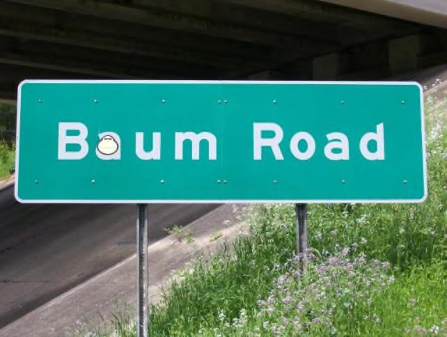

126 Sticker placed on structure this would not meet desired MRP standards. Sticker placed on guardrail this would not meet desired MRP standards. Spray paint graffiti on sign panel this would not meet desired MRP standards. The sticker on this sign would not meet desired MRP standards. Graffiti on wall, this would not meet desired MRP standards. 122
127 TURF CONDITION: Turf in the mowing area is 75% free of undesired vegetation. Unwanted vegetation found growing on or out of Mechanically Stabilized Earth (MSE) and Sound Wall greater than 6 inches in length and in 8 separate locations, and / or no more than 7.5 square feet of unwanted vegetation for any 50 square foot area of paved shoulder, pavement Joints, concrete traffic separators, curb/asphalt joints and under guardrail. No vegetation exists causing damage or displacement to the evaluated asset structure. Vegetation damage is defined as defects both greater than 0.5 square feet in area and deeper than 1.5 inches when measured. Vegetation displacement is defined as vertical, horizontal, or lateral movement in an MSE / Sound Wall of more than 1 inch or in a Pavement Structure of more than 2 inches. Turf Condition Turf is grass or other vegetation considered desirable for the particular roadside location. Properly maintained and desired vegetation provides a pleasing appearance but, primarily, it presents less chance of shoulder and slope defects (ruts, washouts, wash boarding), thereby, providing a safe recovery area for motoring traffic. Unwanted Vegetation This characteristic is the encroachment untreated, unwanted vegetation growing within the right-of-way on MSE, sound walls, paved shoulders, concrete traffic separators, curb/asphalt joints and miscellaneous pavement under guardrail, cable rail, and barrier wall. Evaluation: Determine the mowing area within the sample point. Turf condition will normally be evaluated within the established mowing limits. Occasionally, mowing limits are changed and areas are left to regenerate. These areas, in the first stages of regeneration, will appear to be within mowing limits and probably will contain undesirable vegetation. Rate all MSE, sound walls, paved shoulders, and miscellaneous pavement under guardrail (to include cable rail, traffic separators, and barrier wall) within the sample point. Each MSE and/or sound wall within the sample point shall have no more than 8 separate locations on the wall with untreated vegetation growing greater than 6 inches in length or height. No unwanted, untreated vegetation is growing out of the paved shoulders for 85% more than 7.5 square feet of any 50 square foot area. No unwanted, untreated vegetation is growing on to, or out of miscellaneous pavement under guardrail, cable rail, traffic separators, perimeter, and/or barrier walls, for 85% more than 7.5 square feet of any 50 square foot area. Measure the length of any cracks, joints, and square foot area with untreated vegetation growing out of the pavement in any 50 square foot area. There should not be more than 7.5 square feet of untreated unwanted vegetation growing on the paved shoulder, concrete traffic separators, curb/asphalt joints and/or miscellaneous pavement under guardrail, cable rail, traffic separators, perimeter, and/or barrier walls, for any 50 square foot area. For purposes of evaluating this characteristic, one linear foot of untreated unwanted vegetation growing in pavement cracks should be calculated as one square foot not meeting desired conditions. No vegetation exists causing damage or displacement to the evaluated asset structure. Vegetation damage is defined as defects both greater than 0.5 square feet in area and deeper than 1.5 inches when measured. Vegetation displacement is defined as vertical, horizontal, or lateral movement in an MSE / Sound Wall of more than 1 inch or in a Pavement Structure of more than 2 inches. NOTE: Do not evaluate vegetation designed to grow on or cover sound walls. 123
128 When mowing limits have been extended due to adjoining property improvement or new development, a transition period (one rating period) is required to establish desirable turf conditions. Considerations should be given when these situations are encountered Turf in the mowing area should be 75% free of the following undesired vegetation alone or in combination: 1. Cogon grass 6. Ragweed 11. Sandspur 2. Vaseygrass 7. Castor Bean 12. Spanish Needle 3. Johnsongrass 8. Maiden Cane 13. Crowsfoot 4. Broomsedge 9. Rhodesgrass 14. Tropical Soda Apple 5. Dogfennel 10. Goosegrass Bare ground is defined as any single area (5 square feet) 95% free of vegetation. Purposely stabilized areas (lime rock, shell, etc.) shall not be considered as bare ground and not included in the turf evaluation. Turf grasses that appear to be dead may actually be dormant and shall be considered to meet desired maintenance conditions, if in dormant stage. Calculate the mowing area. Determine the area of undesirable vegetation within the mowing area. Divide the undesirable vegetation area by the total mowing area and multiply by 100. If the resulting percentage is greater than 25%, then the sample does not meet desired maintenance conditions for Turf Condition. Turf condition does not meet MRP standards when any of the following exist: 1) If more than 25% of the undesirable vegetation is present within the mowing limits of the sample. 2) If more than 50 cumulative square feet of bare ground is present in the turf evaluation area. Unwanted Vegetation does not meet MRP standards when any of the following exist: 1) When any MSE, and/or sound wall has 8 separate locations with untreated vegetation growing greater than 6 inches in height or length. 2) Paved shoulder areas with more than 7.5 square feet of untreated vegetation growing in a 50 square foot area. 3) Miscellaneous pavement under guardrail, cable rail, and/or barrier wall has more than 7.5 square feet of untreated vegetation growing in a 50 square foot area. 4) No vegetation exists causing damage or displacement to the evaluated asset structure. 124


129 UNDESIRABLE VEGETATION Cogon grass / Imperata cylindrica Vaseygrass / Paspalum urvillei Johnsongrass / Sorghum halpense Johnsongrass Dogfennel / Eupatorium capillifolium 125


130 UNDESIRABLE VEGETATION Ragweed / Ambrosia artemisiifolia Ragweed Castor bean / Ricinus communis Castor bean 126


131 UNDESIRABLE VEGETATION Broomsedge / Andropogon virginicus Maidencane / Panicum hemitomon Rhodesgrass / Chloris gayana Rhodesgrass 127


132 UNDESIRABLE VEGETATION Goosegrass / Eleusine indica Goosegrass Goosegrass. 128


")

133 UNDESIRABLE VEGETATION Sandspur / Cenchrus incertus Sandspur Spanish Needle / Bidens bipinnata or pilosa (typ) Spanish Needle Spanish Needle without flower Spanish Needle with flower 129


134 UNDESIRABLE VEGETATION Crowfootgrass / Dactyloctenium aegyptium Tropical Soda Apple / Solanum viarum 130


135 UNDESIRABLE VEGETATION An example of good turf conditions. Dog Fennel and Ragweed in the turf. Calculate the percentage of undesirables in the mowing area. If more than the standard, then it does not meet MRP standards. 131


136 UNDESIRABLE VEGETATION Spanish Needle in the mowing area. Spanish Needle in median. Spanish Needle in median. Measure the area of bare ground. If more than 50 cumulative square feet of bare ground is present within the mowing limits of the sample then the turf does not meet MRP standards. 132


137 UNDESIRABLE VEGETATION Example of vegetation growing on an MSE wall. Example of Vegetation growing on paved shoulder and under guardrail. Examples of unwanted vegetation growing out of cracks in pavement. 133
138 DATA ENTRY This section describes the steps necessary to key in the sample scores which will be included in the final report. A valid FDOT user identification and password is required. In addition, access must be granted to the user by the Office of Maintenance in Tallahassee. 134
 will be displayed. Press the ENTER key to continue.")

139 Logon to TSO using an FDOT assigned user identification (userid) and password. If your Logon is successful, three asterisks (***) will be displayed. Press the ENTER key to continue. The Master Application Menu will be displayed. User response: Press PF3 to get to a READY Prompt. At the READY prompt, type MAINT and press the ENTER key. The following broadcast message screen will be displayed. User response: Press the ENTER key. 135
 and press")
 and press")
140 The Maintenance Menus will be displayed. User response: Choose option 14 (MRP MENU) and press the ENTER key. The MRP Menu will be displayed. User response: Choose option 3 (MRPEDIT) and press the ENTER key. 136

141 The MRP Edit Main Menu will be displayed. User response: Select option 1 and press ENTER to begin edit process. The data entry panel will be displayed. User response: Key in data from field coding sheet. Use TAB key to move cursor. 137
ATTACHMENT 50-1: PERFORMANCE AND MEASUREMENT TABLE
 1) PAVEMENT 1.1 Ride quality All roadways have a smooth surface course (including bridge deck approaches, covers, gratings, frames and boxes). 24 hours 28 days 6 months a. Measurement of International
APPENDIX C INLETS. The application and types of storm drainage inlets are presented in detail in this Appendix.
 Storm Drainage 13-C-1 APPENDIX C INLETS 1.0 Introduction The application and types of storm drainage inlets are presented in detail in this Appendix. 2.0 Inlet Locations Inlets are required at locations
Road Maintenance Visual Guide: Introduction
 Road Maintenance Visual Guide: Introduction The One Network Road Classification (ONRC) was born from the opportunity for a better and more transparent way to plan and invest in maintaining and operating
Pavement Surface Evaluation and Rating. Manual RATING RATING RATING PASER RATING. Concrete Roads
 PASER MANUAL FOR CONCRETE ROADS PAVEMENT ENGINEERING SERVICES PASER RATING SUNFLOWER VILLAGE HOMES ASSOCIATION 45800 HANFORD ROAD CANTON, MICHIGAN SME Project Number: 074170.00 July 1, 2016 Pavement Surface
Roadway Surfaces and Traffic Control Elements
 Roadway Surfaces and Traffic Control Elements Lines of Business: General Liability, Public Officials Liability www.tridentinsurance.net Risk Control Strategy/Key Issues: To establish and document a program
CHAPTER B TABLE OF CONTENTS
 July 2006 Page B-1 CHAPTER B TABLE OF CONTENTS B.00 Introduction B.01 Definitions B.02 Maintenance Levels B.03 Definition of Traveled Way B.04 Policy for Performing Roadbed Maintenance Work B.05 Surface
OKLAHOMA DEPARTMENT OF TRANSPORTATION SPECIAL PROVISION FOR PAVEMENT AND BRIDGE DECK SMOOTHNESS
 430-2QA(a-i) 09 OKLAHOMA DEPARTMENT OF TRANSPORTATION SPECIAL PROVISION FOR PAVEMENT AND BRIDGE DECK SMOOTHNESS These Special Provisions amend and where in conflict, supersede applicable sections of the
SECTION 14 - RESTORATION OF SURFACES TABLE OF CONTENTS
 SECTION 14 - RESTORATION OF SURFACES TABLE OF CONTENTS Section Page SECTION 14 RESTORATION OF SURFACES... 14.1 14-1 GENERAL... 14.1 14-2 PRIVATE ROADS... 14.1 14-3 STREETS AND PARKING LOTS... 14.1 14-3.01
MODULE 10 Road Ranger Work Zones
 MODULE 10 Road Ranger Work Zones Module 10 1 Purpose of the Course To train personnel who may be required to assist motorists and emergency personnel within the highway right-of-way, as part of their Road
Construction Requirements for Installation of Utilities in the Public Right-of-way of McPherson County, Kansas October 2011
 Construction Requirements for Installation of Utilities in the Public Right-of-way of McPherson County, Kansas October 2011 General Provisions and Specifications - These provisions and specifications shall
SECTION 26 - COLD PLANE ASPHALT CONCRETE PAVEMENT TABLE OF CONTENTS
 SECTION 26 - COLD PLANE ASPHALT CONCRETE PAVEMENT TABLE OF CONTENTS Section Page 26-1 GENERAL... 26.1 26-2 PAVEMENT KEYCUTTING... 26.1 26-3 PAVEMENT PLANING... 26.2 26-4 PLANED PAVEMENT CONFORMS... 26.3
Computer-Aided Maintenance Management
 52 TRANSPORTATION RESEARCH RECORD 1276 Computer-Aided Maintenance Management JOHN P. ZANIEWSKI AND MICHAEL J. WILES A maintenance management system (MMS) allows managers to organize and control maintenance
Maintenance Assessment Program (MAP) Manual. Produced By South Carolina Department of Transportation
 Manual. Produced By South Carolina Department of Transportation") Maintenance Assessment Program (MAP) Manual Produced By South Carolina Department of Transportation March 1, 2014 South Carolina Maintenance Assessment Program Manual CHAPTER 1... 3 Introduction... 3 CHAPTER
Maintenance Assessment Program (MAP) Manual Produced By South Carolina Department of Transportation March 1, 2014 South Carolina Maintenance Assessment Program Manual CHAPTER 1... 3 Introduction... 3 CHAPTER
Streets Evaluation Manual
 Streets Evaluation Manual 1 Contents Introduction 2 Asphalt Pavement Distress 3 Evaluation 4 Surface Defects 4 Surface Deformation 6 Cracks 7 Patches and Potholes 11 Rating Pavement Surface Condition 12
Implementing a Pavement Management System PASER Based City of Omaha, NE
 Implementing a Pavement Management System PASER Based City of Omaha, NE Introductions JESS HASTINGS, PE Project Manager 10 Years of Experience TIM O BRYAN, PE Senior Project Manager 30 Years of Experience
CONTINUOUSLY REINFORCED CONCRETE AND UNPAVED ROADS CONDITION SURVEY FIELD MANUAL PUBLICATION 343 APRIL 2017 PUB 343 (4-17)
") CONTINUOUSLY REINFORCED CONCRETE AND UNPAVED ROADS CONDITION SURVEY FIELD MANUAL PUBLICATION 343 APRIL 2017 PREPARED BY: BUREAU OF MAINTENANCE AND OPERATIONS ASSET MANAGEMENT DIVISION P.O. Box 3437 HARRISBURG,
CONTINUOUSLY REINFORCED CONCRETE AND UNPAVED ROADS CONDITION SURVEY FIELD MANUAL PUBLICATION 343 APRIL 2017 PREPARED BY: BUREAU OF MAINTENANCE AND OPERATIONS ASSET MANAGEMENT DIVISION P.O. Box 3437 HARRISBURG,
SECTION GENERAL EXCAVATION
 02210-1 of 11 SECTION 02210 GENERAL EXCAVATION 02210.01 GENERAL A. Description 1. General excavation shall include but not necessarily be limited to, excavation and grading for general site work, roadways,
Jobs & Transportation Ramping it Up Roadway and Traffic Dan Groh, P.E.
 Jobs & Transportation Ramping it Up Roadway and Traffic Dan Groh, P.E. Ohio DOT Work Zone Process Review Ohio DOT Work Zone Process Review This review was conducted by the Ohio Department of Transportation
Curb Ramps [ 4.7.3] [ 4.7.2; 4.8.2; 4.1.6(3)(a)] [ 4.3.7] ADA Accessibility Survey Instructions Curb Ramps Page 1 of 6
![Curb Ramps [ 4.7.3] [ 4.7.2; 4.8.2; 4.1.6(3)(a)] [ 4.3.7] ADA Accessibility Survey Instructions Curb Ramps Page 1 of 6](/thumbs/73/68272859.jpg "Curb Ramps [ 4.7.3] [ 4.7.2; 4.8.2; 4.1.6(3)(a)] [ 4.3.7] ADA Accessibility Survey Instructions Curb Ramps Page 1 of 6") : Curb Ramps 1 [ 4.7.3] Only measure the width of the ramp section of the curb ramp (labeled ramp to the right). The ramp section of a curb ramp is also known as the ramp run. If the curb ramp has flared
: Curb Ramps 1 [ 4.7.3] Only measure the width of the ramp section of the curb ramp (labeled ramp to the right). The ramp section of a curb ramp is also known as the ramp run. If the curb ramp has flared
LOCATION AND DESIGN DIVISION
 VIRGINIA DEPARTMENT OF TRANSPORTATION LOCATION AND DESIGN DIVISION INSTRUCTIONAL AND INFORMATIONAL MEMORANDUM GENERAL SUBJECT: Design Exceptions / Waivers SPECIFIC SUBJECT: Design Exception Request Form
EXCELLENCE IN CONCRETE PAVEMENT AWARDS NOMINATION FORM
 EXCELLENCE IN CONCRETE PAVEMENT AWARDS NOMINATION FORM Completed forms are due in the NCPA office no later than Tuesday, October 23, 2018 for projects substantially complete in 2018. (Please feel free
CHAPTER 4 GRADE SEPARATIONS AND INTERCHANGES
 CHAPTER 4 GRADE SEPARATIONS AND INTERCHANGES 4.0 INTRODUCTION The ability to accommodate high volumes of intersecting traffic safely and efficiently through the arrangement of one or more interconnecting
SECTION 13 - EXISTING FACILITIES TABLE OF CONTENTS
 SECTION 13 - EXISTING FACILITIES TABLE OF CONTENTS Section Page 13-1 GENERAL... 13.1 13-1.01 Preservation of Property... 13.1 13-1.02 Overloading, Pavement Protection & Repair... 13.1 13-2 REMOVING EXISTING
CHAPTER 3 SCOPE SUMMARY
 CHAPTER 3 SCOPE SUMMARY GENERAL The SDDOT is an active member of AASHTO to share common national design standards for the state highway system. The AASHTO Task Force on Geometric Design has completed the
Measures for Highway Maintenance Quality Assurance
 Measures for Highway Maintenance Quality Assurance Teresa M. Adams Professor, Civil and Environmental Engineering Director, Midwest Regional University Transportation Center Janille Smith Graduate Research
IGGA Guide Specification: Conventional Diamond Grinding of City Streets Introduction
 IGGA Guide Specification: Conventional Diamond Grinding of City Streets Introduction This standard developed, by the International Grooving and Grinding Association (IGGA), specifies the procedures for
GENERAL NOTES ROADWAY CONSTRUCTION RD0001-1A ISSUED:2017 REVISED: --
 ROADWAY CONSTRUCTION NOTES 1. ALL RIGHT-OF-WAY OTHER THAN ROADWAY AREAS SHALL BE SODDED. ALL SLOPE STEEPER THAN 6:1 SHALL REQUIRE SODDING. THE CITY RESERVES THE RIGHT TO REQUIRE SODDING IN SPECIAL AREAS
603 - ASPHALT PAVEMENT SMOOTHNESS SECTION 603 ASPHALT PAVEMENT SMOOTHNESS
 SECTION 603 ASPHALT PAVEMENT SMOOTHNESS 603.1 DESCRIPTION Determine the smoothness of the pavement surface and correct the deficiencies as specified in the Contract Documents. For the purposes of this
GEOMETRIC DESIGN CRITERIA for Non-freeway Resurfacing, Restoration, and Rehabilitation Projects
 GEOMETRIC DESIGN CRITERIA for Non-freeway Resurfacing, Restoration, and Rehabilitation Projects SEPTEMBER 1989 Arkansas State Highway and Transportation Department GEOMETRIC DESIGN CRITERIA for Non-freeway
Field Guide on. Safe Maintenance and. Work Zone Operations
 Field Guide on Installation and Removal of Temporary Traffic Control for Safe Maintenance and Work Zone Operations August 2008 Introduction This field guide provides field personnel with introductory guidance
B HOT MIX, HOT LAID ASPHALTIC CONCRETE OPSS 313
 B 313-1 OPSS 313 313-1.1 GENERAL HL,, Mixture, and/or Mix, is hot mixed, hot laid asphaltic concrete, used for pavement construction and other uses. 1. HL 1 This dense graded surface course mix is used
CHECKLIST FOR STREETS, INLETS, AND STORM SEWER DESIGN
 CHECKLIST FOR STREETS, INLETS, I. STREET CLASSIFICATION AND DESIGN CRITERIA A. Determine drainage classification for the roadway section using Table 7-1 or Table 7-2. B. Determine the allowable flow depth
Chapter 7. Street Drainage. 7.0 Introduction. 7.1 Function of Streets in the Drainage System. 7.2 Street Classification
 7. Introduction This chapter summarizes methods to evaluate runoff conveyance in various street cross sections and curb types in the Town of Castle Rock and identifies acceptable upper limits of street
SECTION 14 - RESTORATION OF SURFACES TABLE OF CONTENTS
 SECTION 14 - RESTORATION OF SURFACES TABLE OF CONTENTS Section Page 14-1 GENERAL... 14.1 14-2 PRIVATE ROADS... 14.1 14-3 STREETS AND PARKING LOTS... 14.1 14-3.01 Aggregate Base... 14.1 14-3.02 Asphalt
SIDEWALK CONSTRUCTION AND REPAIR
 SIDEWALK CONSTRUCTION AND REPAIR Q: Why all the concern over sidewalks? A: Sidewalks are the avenues and streets of pedestrian traffic. Residents should maintain the sidewalks as best as they can. The
IGGA Guide Specification: Conventional Diamond Grinding for Pavement Preservation Introduction
 IGGA Guide Specification: Conventional Diamond Grinding for Pavement Preservation Introduction This standard developed, by the International Grooving and Grinding Association (IGGA), specifies the procedures
SECTION 6. ROAD CONSTRUCTION STANDARDS
 SECTION 6. ROAD CONSTRUCTION STANDARDS Construction of new roads or reconstruction of existing roads proposed for dedication to the County shall conform to the standards set forth in this section. Roads
CITY OF ANN ARBOR, MICHIGAN Public Services Area/Project Management Unit 301 E. Huron Street P.O. Box 8647, Ann Arbor, Michigan 48107
 CITY OF ANN ARBOR, MICHIGAN Public Services Area/Project Management Unit 301 E. Huron Street P.O. Box 8647, Ann Arbor, Michigan 48107 Web: www.a2gov.org Printed on recycled paper May 17, 2016 Subject:
SUBDIVISION SECTION STREET DESIGN MANUAL
 CITY OF ANAHEIM SUBDIVISION SECTION STREET DESIGN MANUAL A. INTRODUCTION : POLICY STATEMENT B. STREET CLASSIFICATION C. STREET STANDARDS REQUIREMENTS Requirements Approval of Street Improvement Plans Widening
B510-5 REMOVAL-PAVEMENT WORK OPSS 510. CDED B Removal CDED B Reclaim Asphalt Pavement
 B510-5 OPSS 510 510-5.1 GENERAL This section is for Pavement Work removal tender items. The work covered by these tender items includes the removal and disposal of materials. 510-5.2 REFERENCES CDED B510-0
City of Regina Standard Construction Specification SECTION 2350 PLACEMENT OF ASPHALTIC CONCRETE SURFACE 1.0 GENERAL. 1.1 Scope
 1.0 GENERAL 1.1 Scope 2.0 PRODUCTS 1.1.1 The work shall consist of placing asphaltic concrete to a compacted thickness conforming to the lines, grades, and cross-sections as shown on the plan or as designated
CHAPTER 12 INSTALLATION OF UTILITIES AND OTHER SYSTEMS TABLE OF CONTENTS
 CHAPTER 12 INSTALLATION OF UTILITIES AND OTHER SYSTEMS TABLE OF CONTENTS Section Title Page 12.1 General... 12-1 12.2 Design Standards... 12-1 12.2.1 General Requirements...12-1 12.2.2 Minimum Depth...12-1
SECTION 503 TEMPORARY PAVEMENT RESTORATION
 SECTION 503 TEMPORARY PAVEMENT RESTORATION 503-1 DESCRIPTION: This work consists of furnishing, placing, compacting, and maintaining a temporary pavement surface suitable for driving in accordance with
STATE OF OHIO DEPARTMENT OF TRANSPORTATION SUPPLEMENTAL SPECIFICATION 806 ASPHALT CONCRETE WITH JOINT DENSITY FOR MULTI-LANE HIGHWAYS.
 STATE OF OHIO DEPARTMENT OF TRANSPORTATION SUPPLEMENTAL SPECIFICATION 806 ASPHALT CONCRETE WITH JOINT DENSITY FOR MULTI-LANE HIGHWAYS March 2, 2015 806.01 Description 806.02 JMF Field Adjustments 806.03
21 PAVEMENTS General Administrative Requirements Standards Personnel Certification
 21 PAVEMENTS 21.1 General The Design-Builder shall conduct all Work necessary to meet the requirements associated with all Project pavements. The permanent pavement structure for all Project roadways is
ENGINEERING DESIGN & IMPROVEMENT STANDARDS
 ENGINEERING DESIGN & IMPROVEMENT STANDARDS 2016 Prepared by: Engineering Division For latest edition of these Improvement Standards, refer to City of Visalia website at: www.visalia.city/engineeringdocuments
HAWAII DEPARTMENT OF TRANSPORATION HIGHWAYS DIVISION PAVEMENT PREVENTIVE MAINTENANCE GUIDELINES JUNE 2003
 HAWAII DEPARTMENT OF TRANSPORATION HIGHWAYS DIVISION PAVEMENT PREVENTIVE MAINTENANCE GUIDELINES JUNE 2003 Reviewed and accepted by FHWA on September 29, 2003 Note: Guidelines was revised on to correct
Maintenance, Construction & Secondary Roads. Terry Gibson, PE Chief Engineer February 20, 2013
 Maintenance, Construction & Secondary Roads Terry Gibson, PE Chief Engineer February 20, 2013 State versus local responsibility Division structure Allocations Flexibility in funding Implications of not
SECTION ASPHALT PAVING AND SURFACING
 SECTION 02500 ASPHALT PAVING AND SURFACING PART 1 - GENERAL 1.01 WORK INCLUDED A. Traffic control as required to divert vehicular and pedestrian traffic around construction. B. Spreading and compacting
PCC Pavement Rideability
 Supplemental Technical Specification for PCC Pavement Rideability SCDOT Designation: SC-M-502 (04/16) 1. SCOPE 1.1. The Resident Construction Engineer (RCE) will evaluate Portland cement concrete (PCC)
SECTION IV. PIPELINE EXCAVATION AND BACKFILL
 SECTION IV. PIPELINE EXCAVATION AND BACKFILL A. Description of Work B. Surface Types C. Backfill D. Surface Restoration A. DESCRIPTION OF WORK 1. Extent: Excavation of trenches for pipelines shall include
Construction Cost Estimation Preparation Manual for Preliminary Design (English Units)
") 10/16/2014 Construction Cost Estimation Preparation Manual for Preliminary Design (English Units) July 2002 Prepared by Construction Cost Estimating Unit Program Support Services 10/16/2014 Table of Contents
10/16/2014 Construction Cost Estimation Preparation Manual for Preliminary Design (English Units) July 2002 Prepared by Construction Cost Estimating Unit Program Support Services 10/16/2014 Table of Contents
CONSTRUCTION SURVEY. Construction survey includes personnel, equipment, and supplies required for, but not limited to, the following:
 CONSTRUCTION SURVEY PART 1 - GENERAL 1.01 SECTION INCLUDES Construction survey includes personnel, equipment, and supplies required for, but not limited to, the following: A. Construction Survey: 1. Project
NYSDOT TRANSPORTATION MAINTENANCE DIVISION PAVING PROJECT QUALITY ASSURANCE ASSESSMENT Rating Guidelines (Revision #1)
") NYSDOT TRANSPORTATION MAINTENANCE DIVISION PAVING PROJECT QUALITY ASSURANCE ASSESSMENT Rating Guidelines (Revision #1) INTRODUCTION The condition assessment is intended to be performed from a customer
NYSDOT TRANSPORTATION MAINTENANCE DIVISION PAVING PROJECT QUALITY ASSURANCE ASSESSMENT Rating Guidelines (Revision #1) INTRODUCTION The condition assessment is intended to be performed from a customer
B510-5 REMOVAL-PAVEMENT WORK OPSS 510. CDED B Removal CDED B Reclaim Asphalt Pavement
 B510-5 OPSS 510 510-5.1 GENERAL This section is for Pavement Work removal tender items. The work covered by these tender items includes the removal and disposal of materials. 510-5.2 REFERENCES CDED B510-0
COUNTY OF YUBA DEPARTMENT OF PUBLIC WORKS IMPROVEMENT STANDARDS
 COUNTY OF YUBA DEPARTMENT OF PUBLIC WORKS IMPROVEMENT STANDARDS TABLE OF CONTENTS SECTION 1 PURPOSE AND DEFINITIONS 1.1 PURPOSE:... 1 1.2 DEFINITIONS:... 1 SECTION 2 GENERAL REQUIREMENTS 2.1 PLANS BY AN
CHAPTER 2. Restricted Residential ½ Street** Design Speed 25 MPH 25 MPH 25 MPH 25 MPH 40 MPH 50 MPH 55 MPH
 CHAPTER 2 201 ROADS 201.1 General This section is to assist the designer in determining what is needed for the design of roads in public rights-of-way. For these standards, the terms used are: Restricted
SECTION 1 GENERAL NOTES
 ISSUE DATE NOVEMBER 1st, 2011 SECTION 1 Page List Page Number Page Title COVER COVER GN-01 PAGE 1 GN-02 PAGE 2 GN-03 PAGE 3 GN-04 PAGE 4 GN-05 PAGE 5 GN-06 PAGE 6 GN-07 PAGE 7 : 1. (CCU) STANDARD SPECIFICATIONS
SECTION TRAFFIC REGULATIONS
 PART 1 GENERAL 1.1 DESCRIPTION A. Traffic Control permits, notifications, mobilization, temporary signs, barriers, lights, flagging personnel, striping, markings, and demobilization and removal. 1.2 RELATED
Mobile Work Zones. Traffic Control in Short Duration / Guidelines for M0WING ZONE AHEAD WORK ROAD SHOULDER WORK RIGHT LANE CLOSED AHEAD SIGNAL AHEAD
 M0WING ZONE ROAD WORK AHEAD SHOULDER WORK RIGHT LANE CLOSED AHEAD SIGNAL WORK AHEAD Guidelines for Traffic Control in Short Duration / Mobile Work Zones Guidelines for Traffic Control in Short Duration
SECTION 9000 MAINTENANCE SERVICES
 SECTION 9000 MAINTENANCE SERVICES 9000 MAINTENANCE SERVICES... 1 9001 LEGISLATIVE AUTHORITY... 1 9002 GENERAL MAINTENANCE... 1 9003 PEDESTRIAN OVERPASSES... 1 9003.1 GENERAL MAINTENANCE... 1 9003.2 WINTER
CHAPTER 11 - RESTORATION OF SURFACE IMPROVEMENTS
 CHAPTER 11 - RESTORATION OF SURFACE IMPROVEMENTS 11.1 GENERAL The Developer/Contractor shall be responsible for the protection and the restoration or replacement of any improvements existing on public
MICHIGAN DEPARTMENT OF TRANSPORTATION SPECIAL PROVISION FOR MATERIALS AND WORKMANSHIP PAVEMENT WARRANTY
 MICHIGAN DEPARTMENT OF TRANSPORTATION SPECIAL PROVISION FOR MATERIALS AND WORKMANSHIP PAVEMENT WARRANTY CFS:EMC 1 of 8 APPR:KPK:CJB:06-13-17 FHWA:APPR:06-14-17 a. Description. The materials and workmanship
EXISTING ROADWAY CONDITION ASSESSMENT REPORT (ERCAR) SAMPLE OUTLINE
 SAMPLE OUTLINE") EXISTING ROADWAY CONDITION ASSESSMENT REPORT (ERCAR) SAMPLE OUTLINE The Existing Roadway Condition Assessment Report (ERCAR) should include the evaluation of all elements against new construction criteria.
EXISTING ROADWAY CONDITION ASSESSMENT REPORT (ERCAR) SAMPLE OUTLINE The Existing Roadway Condition Assessment Report (ERCAR) should include the evaluation of all elements against new construction criteria.
Performance Audit: Pavement Condition Measures October 2008
 Performance Audit: Pavement Condition Measures October 2008 City Auditor City of Lawrence, Kansas October 2, 2008 Members of the City Commission The city measures the condition of streets and uses the
550 Surface Treatments
 Table of Contents 550 Surface Treatments... 550-1 550.1 Introduction... 550-1 551 Crack Sealing... 550-1 551.1 Project Selection... 550-1 551.2 Design Considerations... 550-1 552 Chip Sealing... 550-2
Section 505. CHIP SEALS
 Section 505. CHIP SEALS 505.01. Description. This work consists of preparing the pavement surface and providing and placing a single chip seal, double chip seal, or shoulder chip seal. 505.02. Materials.
Chapter 1. General Design Information. Section 1.02 Structure Selection and Geometry. Introduction
 Chapter 1 Bridge Design Manual General Design Information Section 1.02 Selection and Geometry Introduction Selection or Rehabilitation Report This section of the design manual provides guidance on the
COUNTY OF ALBEMARLE. Community Development Department 401 McIntire Road, Room 227 Charlottesville, Virginia (434)
") COUNTY OF ALBEMARLE ZONING INFORMATION PACKET (For building permits for a structure on a property with a site plan) Community Development Department 401 McIntire Road, Room 227 Charlottesville, Virginia
COUNTY OF ALBEMARLE ZONING INFORMATION PACKET (For building permits for a structure on a property with a site plan) Community Development Department 401 McIntire Road, Room 227 Charlottesville, Virginia
SECTION CURB RAMPS AND OTHER MINOR CONCRETE FACILITIES. Part 1 - General Work Included Related Requirements...
 SECTION 02530 CURB RAMPS AND OTHER MINOR CONCRETE FACILITIES CONTENTS: Part 1 - General... 1 1.01 Work Included... 1 1.02 Related Requirements... 1 1.03 Inspection And Tests... 1 1.04 Quality Assurance...
Engineering Design Services for Safety Improvements along CR 476 from the Hernando County Line to US 301 (SR 35) Sumter County, Florida
 Sumter County, Florida") Engineering Design Services for Safety Improvements along CR 476 from the Hernando County Line to US 301 (SR 35) Sumter County, Florida November 7, 2014 SUBMITTED BY: Dewberry Bowyer-Singleton 520 South
Engineering Design Services for Safety Improvements along CR 476 from the Hernando County Line to US 301 (SR 35) Sumter County, Florida November 7, 2014 SUBMITTED BY: Dewberry Bowyer-Singleton 520 South
District No.: Applicant: Type of Work:
 Fee: Permit No.: District No.: Applicant: Type of Work: FOR DEPARTMENT USE ONLY APPLICATION AND ANNUAL PERMIT FOR TELECOMMUNICATION OCCUPANCY OF NEVADA DEPARTMENT OF TRANSPORTATION RIGHT-OF-WAY (Under
Section 502. HMA CRACK TREATMENT
 502.01 Section 502. HMA CRACK TREATMENT 502.01. Description. This work consists of treating cracks in Hot Mix Asphalt (HMA) surfaces using either a saw or rout and seal process or an overband process.
CUYAHOGA COUNTY ENGINEER
 CUYAHOGA COUNTY ENGINEER DRAINAGE MANUAL Supplement to O.D.O.T. LOCATION and DESIGN MANUAL, Volume 2, Drainage Design, Section 1000 and 1100 May 28, 2010 Revisions to the July 29, 2009 edition are noted
Project Initiation Form
 Meeting Date: The Project Initiation Form should be completed in conjunction with the Level 2 Screening Form. Process Leads and/or Planners should complete the Project Initiation Form to document coordination
SPECIAL PROVISIONS - SP2014 BOOK Page 1 October 8, 2013
 SPECIAL PROVISIONS - SP2014 BOOK Page 1 S-1 (2104) REMOVE AND REPLACE BITUMINOUS PAVEMENT (ADA) Always include SP2014-119 (PLANT MIXED ASPHALT PAVEMENT) or SP2014-121 (PLANT MIXED ASPHALT PAVEMENT FOR
CITY OF DES PLAINES-CONCRETE PROGRAM SIDEWALK, CURB AND DRIVEWAY GUIDELINES
 CITY OF DES PLAINES-CONCRETE PROGRAM SIDEWALK, CURB AND DRIVEWAY GUIDELINES SUMMARY AND INTENT OF PROJECT The City of Des Plaines Curb and Sidewalk Program is intended to repair hazardous sidewalk and
36 JASPER THPMAS ROAD CRAWFORDVILLE, FL.
 N ARRAN RD. N US 319 CRAWFORDVILLE HWY SR 61 SHADEVILLE RD. WAKULLA HARVEY MILL ROAD US 319 PREBLE-RISH INC CIVIL SURVEYING SITE PLANNING 36 JASPER THPMAS ROAD CRAWFORDVILLE, FL. 32327 GENERAL NOTES: 1.
Appendix B. Pavement Guidelines for Treatment of High Stress Locations
 Appendix B Pavement Guidelines for Treatment of High Stress Locations PAVEMENT GUIDELINES FOR TREATMENT OF HIGH STRESS LOCATIONS BACKGROUND: These guidelines are intended to be used to reduce or eliminate
Department of Building and Zoning Approaches and Sidewalks for ONE AND TWO FAMILY CONSTRUCTION
 Department of Building and Zoning Approaches and Sidewalks for ONE AND TWO FAMILY CONSTRUCTION GENERAL ITEMS SUBGRADE Prior to pouring concrete all subgrades must be wetted and compacted. All formwork
EXCAVATION WORK IN PUBLIC RIGHT-OF-WAY GENERAL NOTES
 CITY OF SANTA MONICA Department of Public Works Civil Engineering Division 1685 Main, Room 116 Santa Monica, CA 90401 Tel: (310) 458-2240 or (310) 458-8737 EXCAVATION WORK IN PUBLIC RIGHT-OF-WAY GENERAL
SECTION TRENCHING
 SECTION 31 23 17 TRENCHING PART 1 GENERAL 1.1 SUMMARY A. Section Includes: 1. Excavating trenches for utilities and utility structures. 2. Bedding. 3. Backfilling and compacting to subgrade elevations.
B-PERMIT PLAN CHECK MANUAL
 B-PERMIT PLAN CHECK MANUAL 11. PLAN SHEETS AND NOTES Preformatted B-Permit plans sheets can be downloaded from the internet on the Bureau of Engineering s website. The Plan sheets can be found under the
(D) Surface Slope Bituminous patch in front of the truncated domes must not exceed 5% measured perpendicular to the flow line or edge of roadway.
 Surface Slope Bituminous patch in front of the truncated domes must not exceed 5% measured perpendicular to the flow line or edge of roadway.") Last Revision by CO Special Provisions: 09/14/18 Page 1 S-1 (2104) REMOVE AND REPLACE BITUMINOUS PAVEMENT (ADA) Always include SP2018-143 ((2360) PLANT MIXED ASPHALT PAVEMENT (MSCR)) when using this writeup.
Last Revision by CO Special Provisions: 09/14/18 Page 1 S-1 (2104) REMOVE AND REPLACE BITUMINOUS PAVEMENT (ADA) Always include SP2018-143 ((2360) PLANT MIXED ASPHALT PAVEMENT (MSCR)) when using this writeup.
Appendix A General Conditions to Utility Cut Permanent Restoration
 Appendix A General Conditions to Utility Cut Permanent Restoration Abilities and Experience Appendix A General Conditions to Utility Cut Permanent Restoration All Contractors retained by the utility must
Chapter 8. Inlets. 8.0 Introduction. 8.1 General
 . Introduction This chapter provides criteria and design guides for evaluating and designing storm sewer inlets in the City of Centennial. The review of all planning submittals will be based on the criteria
Pavement Distress Categories
 Pavement Distress Identification Asphalt Pavements Raymond Ong, Purdue University William Flora, INDOT Planning Joyce Stone, INDOT Pavement Engineering Samy Noureldin, INDOT Research Pavement Distress
MAINTENANCE MANAGEMENT SYSTEM
 Approved: Effective: November 15, 2017 Review: October 29, 2017 Office: Maintenance Topic No.: 325-010-001-l Department of Transportation MAINTENANCE MANAGEMENT SYSTEM PURPOSE: To provide a management
Welcome!! Temporary Traffic Control During Maintenance and Short Duration Activities. Training Course 1-1
 Welcome!! Temporary Traffic Control During Maintenance and Short Duration Activities Training Course 1-1 About This Course This material is based upon work supported by the Federal Highway Administration
Plan Preparation Guide. Chapter 2. Typical Sections - Pavement Design
 Plan Preparation Guide Chapter 2 Typical Sections - Pavement Design Section Description Page 1 Typical Sections 2-1 2 Secondary ( C projects) Typical Sections 2-3 3 Base Course 2-4 4 Full Depth Asphalt
Traffic Management Guide to Concrete Overlay Solutions. Dale S. Harrington P.E. Representing CP Tech Center
 Traffic Management Guide to Concrete Overlay Solutions December 5, 2014 ACPA Annual Meeting Dale S. Harrington P.E. Representing CP Tech Center Traffic Management- Concrete Overlays Traffic Management
BASE CONSTRUCTION MATERIALS A Aggregate
 BASE CONSTRUCTION 2211 AGGREGATE BASE 2211.1 DESCRIPTION This work consists of placing aggregate base. 2211.2 MATERIALS A Aggregate... 3138 Provide the class of aggregate as required by the contract. 2211.3
c h a p t e r 4 d e s i g n e x a m p l e s f o r s a n m a t e o c o u n t y A typical residential street intersection
 LOW-DENSITY RESIDENTIAL STREETS: Stormwater Curb Extensions A typical residential street intersection This residential street example illustrates how stormwater curb extensions can be easily retrofitted
CITY OF WILSON. Public Services Engineering. Backfilling, Compaction, & Patching Policy on Existing Pavements
 CITY OF WILSON Public Services Engineering Backfilling, Compaction, & Patching Policy on Existing Pavements INTRODUCTION The City of Wilson recognizes that proper backfilling, compaction, and patching
Portable Changeable Message signs have a wide variety of
 Part 6F (devices) Minnesota MUTCD 2005 with 2007 09 Revisions Part 6F (devices) Federal MUTCD 2009 Part 6F (devices) MN MUTCD Rearranged Sections 6F.55 Portable Changeable Message Signs Portable Changeable
Section 13. Guidelines for the Design of Ground Mounted Sign Supports
 Section 13 BDC11MR-04 13.1 Introduction Highway signs fall into two main categories, which are subdivided as follows: 1. Overhead Signs a. Sign Bridge Structures (GO) b. Sign Cantilever Structures (GO)
ITEM 6 CONCRETE CURBS, GUTTERS, AND SIDEWALKS
 ITEM 6 CONCRETE CURBS, GUTTERS, AND SIDEWALKS 6.1 DESCRIPTION This work shall consist of constructing curbs, gutters, sidewalks, ramps, local depressions and driveways of the form and dimensions shown
York County Engineering Department Roadway Inspection Requirements
 York County Engineering Department Roadway Inspection Requirements The following is a list, in order, of the roadway inspections that are required to be passed by York County before a subdivision can receive
Section XXV Preconstruction Assessments and Damage Mitigation Procedures
 Section XXV Preconstruction Assessments and Damage Mitigation Procedures A. Introduction - In recent years, HRSD has received an increasing number of complaints from residents and locality staff regarding
SECTION TRENCHING & BACKFILLING
 SECTION 02225 - TRENCHING & BACKFILLING 1.0 GENERAL 1.1 Work included in this Section includes trenching and backfilling for underground pipelines and related structures only. 1.2 Reference Specifications