Campus-Wide Cooling Plant Load Analysis & Thermal Energy Storage (TES) System Concept Engineering Study
|
|
|
- Scot Logan
- 6 years ago
- Views:
Transcription


1 North Orange County Community College District Campus-Wide Cooling Plant Load Analysis & Thermal Energy Storage (TES) System Concept Engineering Study Fullerton College Final September 8, 2017
2 Table of Contents 1 EXECUTIVE SUMMARY EXISTING COOLING PLANT ANALYSIS Mini Plant Lot Existing Conditions Existing Distribution Flow Analysis / 500 Chiller Plants Existing Conditions Existing Distribution Flow Analysis Wilshire Chiller Plant Existing Conditions Existing Distribution Flow Analysis CAMPUS PLANNED GROWTH Future Block Level Cooling Load Analysis Future Distribution Flow Analysis Phase I Analysis Phase II Analysis Future Electrical Load Impact THERMAL ENERGY STORAGE (TES) STUDY Concept 1 Full Storage TES Concept (On-Peak & Mid-Peak) Concept 2 Full Storage TES Concept (On-Peak) Concept 3 Partial Storage TES Concept (On-Peak, Mid-Peak, & Off-Peak) TES Life Cycle Cost Analysis Energy Analysis Tools Utility Rates and Escalation Rates Concepts Analyzed Installation and Maintenance Costs, Life Expectancy Summary of Findings Benefit of a Thermal Energy Storage System Energy Incentives Associated with TES System Final Report Page 1
3 4.7 Proposed Future Chiller Plant / TES Concepts Expansion of Central Plant without TES system Concept 1 Full Storage TES Concept (On-Peak & Mid-Peak) Concept 2 Full Storage TES Concept (On-Peak) Concept 3 Partial Storage TES Concept (On-Peak, Mid-Peak, & Off-Peak) ENGINEERING COST ESTIMATES Engineers Opinion of Cost Base Case Expansion of Central Plant without TES system Concept 1 Full Storage TES Concept (On-Peak & Mid-Peak) Concept 2 Full Storage TES Concept (On-Peak) Concept 3 Partial Storage TES Concept (On-Peak, Mid-Peak, & Off-Peak) Existing Central Plant Replacement Cost RECOMMENDATIONS Appendix A CHW Analysis Appendix B - Photos Appendix C Utility Rates Final Report Page 2

4 1 EXECUTIVE SUMMARY BSE Engineering is pleased to submit the results of this campus-wide cooling plant load analysis & thermal energy storage (TES) system concept engineering study. The purpose of this study is to analyze and validate the adequacy of the existing cooling plants, analyze and determine the future cooling needs of the campus based on the proposed build out as indicated in the Campus Master Plan, evaluate TES concepts, sizes, and impact on campus, and provide an engineering cost estimate to assist the campus with project and capital planning. Based on this engineering study, the existing chiller plants serving the existing campus buildings do not have adequate spare capacity to meet the required cooling needs for the master planned campus facilities. Additionally, in the current chiller plant configurations there is limited spare capacity and there is no redundancy on the chillers to allow for scheduled maintenance and repairs. For example, the central plant in Lot 3 has a total capacity of 1200-tons with a total building connected load of 1,536-tons (78% diversity). The existing total installed cooling capacity will not be able to support the projected growth, as depicted in the Fullerton College Facilities Master Plan as shown below. Additional cooling capacities will be required either in the form of adding new chillers to the existing central plants or a combination of adding new chillers along with some Thermal Energy Storage (TES) capacity. Figure 1 - Fullerton College Facilities Master Plan Final Report Page 3


5 An engineering flow analysis of the existing chilled water piping discovered that some of the existing underground chilled water pipes are undersized and need to be replaced. In order to develop a resilient chilled water infrastructure system, this report recommends the creation of a chilled water loop around the campus and identifies the need to add approximately 3,000 linear feet of trenching for approximately 6,000 linear feet of chilled water piping (3000 feet of supply and 3000 feet of return). This study recommends the consolidation of all cooling plants into a single location at Mini Plant Lot 3 with a TES tank located near the plant. To determine the best possible solution for sizing of the TES tank and for increasing the cooling capacity requirements of the chiller plant at Lot 3, BSE analyzed three TES options and conducted a Life Cycle Cost Analysis (LCCA) comparing these options to a base case of adding chiller capacity to meet the required cooling load. The concept options studies were: 1. Concept 1 Full Storage TES (On-Peak & Mid-Peak) a. This option would provide cooling for all campus buildings during both On-Peak (Noon to 6 pm) and Mid-Peak (6 pm to 11 pm & 8 am to Noon) hours. 2. Concept 2 Full Storage TES (On-Peak) a. This option would provide cooling for all campus buildings only during the On- Peak (Noon to 6 pm) hours. 3. Concept 3 Partial Storage TES (On-Peak, Mid-Peak & Off-Peak) a. This option would provide cooling for all campus buildings using a combination of TES and chiller. Chillers will operate 24/7 to either charge the TES tank or to assist the TES tank in meeting the campus loads. Concept 2 Full TES sized to satisfy the On-Peak cooling loads had the best simple pay back at 4.3 years, with savings of $4,694,777 when compared to a non-tes traditional chiller plant. Final Report Page 4

6 BSE understands the challenges facing the District as it relates to making major infrastructure changes to the existing chiller plants and the much needed underground piping infrastructure. To assist with the planning and implementation of this work, BSE has developed a preliminary phased implementation plan based on our review of the project schedule showing the proposed buildout to 2023 as follows: 1. Instructional Building/M&O Building Increase Chiller Capacity to the Mini Plant Lot 3 (To be Completed by 4 th Quarter of 2019) Address the chiller capacity shortage in the Mini Plant Lot 3 by adding a new 600-ton chiller and associated cooling tower. Adding a new 600-ton chiller to the existing 1200-ton plant will provide the capacity needed to add the new Instructional Building and the M&O Building, as well as, providing the needed spare capacity. The chilled water supply and return piping for Instructional Building and M&O will be terminated within a concrete utility vault with isolation valves ready for connection to the proposed buildings. 2. Buildings 300 / 500 Replace Undersized Chilled Water Piping & Extend Piping (To be Completed by 1 st Quarter of 2021) Remove the existing undersized chilled water supply and return from the Mini Plant Lot 3 to Building 300 with piping provisions to serve Building 500 and the proposed Welcome Center. The chilled water supply and return piping for buildings 500 and Welcome Center will be terminated within a concrete utility vault with isolation valves. Chiller in Building 500 shall be removed and associated underground piping from Building 1100 shall be abandoned in place. Provide 10 CHW supply & return (2,500 LF) as highlighted in red Figure 2 - Buildings 300 / 500 Replace Undersized Chilled Water Piping & Extend Piping Final Report Page 5
 tank.")
7 3. TES & Chilled Water Piping Loop (Upon Approved Funding) Implement the recommendations of Concept 2 by extending the chilled water piping to the Fine Arts Building, therefore completing the campus chilled water loop, and installing the recommended 932,000 gallon (70-5 ID x 32-0 water depth) tank. The chilled water supply and return piping for the proposed Performing Arts Building and existing Wilshire Buildings will be terminated within a concrete utility vault with isolation valves ready for extension. Install 10 CHW supply & return completing CHW loop (1,000 LF) highlighted in red Figure 3 - TES & Chilled Water Piping Loop 4. Wilshire Buildings (6 Months Prior to Construction of New Buildings) Extend the chilled water piping from the main campus to the Wilshire Buildings to serve the new Performing Arts Complex, including the second Instructional Building and all other existing buildings. Additional architectural studies will have to be completed in order to determine the best way to route the chilled water piping across Chapman Ave. Install 8 CHW supply & return (2,500 LF) highlighted in red Figure 4 - Wilshire Buildings Final Report Page 6
8 As a general recommendation for all upcoming HVAC retrofit or replacement projects, it is critical for the campus to address some of the existing deficiencies associated with the installed cooling coils and the low delta T condition impacting the chiller plant operations. The recommended TES Concept 2 assumes a central plant delta T of 22-degrees. The existing Mini Plant Lot 3 central plant is designed at a 12-degree delta T. In order for the new central plant and TES system to operate most efficiently, the existing chilled water coils at each existing building will need to be replaced with new coils that are designed at a minimum 20-degree delta T. Increasing the delta T at the existing buildings will also reduce the chilled water flow, which will help reduce excessive pipe velocities and improve the life expectancy of the chilled water loop. Fullerton College would be eligible to participate in the Permanent Load Shifting Program (PLS) with Southern California Edison utility company. PLS incentives include eligibility for reimbursements of up to $875 per kilowatt of shifted cooling load or 50% of the total TES system equipment and installation costs (up to $1.5 million), whichever is less. Based on our current understanding, PLS incentives expire at the end of 2017, however, SCE is still accepting new project reservations provided the installation is completed within 18 months of the approval date. For the purposes of this study, given the uncertainty of the availability of these incentives in the next program cycle, no capital cost reductions are considered in the life cycle cost analysis. The incentives will only make TES installation more attractive and shorten the simple payback periods. Final Report Page 7
9 There are a total of twenty (20) existing buildings on campus that are being analyzed in this study as shown in Table 1. Per the Campus Master Plan, it is estimated that five (5) additional new buildings will be added to the campus-wide chilled water system as indicated in Table 2. Table 1 Existing Buildings Building Number Building Name Cooling Load 1 [Tons] Chilled Water Delta T 1 [Degrees F] Chilled Water Flow Rate 1 [GPM] 100 Administration College Center / Food Services Business & Computer Info South Science Applied Arts / Humanities North Science Technology & Engineering Library Learning Resource Center 182 DX DX 840 Disability Support Service / Mailroom 30 DX DX 900 Technology & Engineering Fine Arts / Art Gallery Music Physical Education Theater Arts Classroom Office Building Student Services / TV Wilshire Auditorium W100 Wilshire Continuing Ed W200 Wilshire Continuing Ed W300 Wilshire Continuing Ed Footnotes: 1. Existing data based on research of available engineering drawings and site investigations. Final Report Page 8
10 Table 2 Planned Future Buildings Future Building Name Planned Square Footage [ASF] Estimated Cooling Load [Tons] Estimate Chilled Water Flow Rate [GPM] Instructional Building 47, Maintenance and Operation Building 13, Welcome Center 29, Performing Arts Complex 25, Instructional Building South of Chapman 35, Total: 151, Footnotes: 1. Estimated Cooling Load based on 233 square foot/ton. 2. Estimated Cooling Load based on 285 square foot/ton. 3. Estimated Cooling Load based on 190 square foot/ton. 4. Estimated Flow Rate based on 18 Delta T. The Child Development Center Complex and Horticulture/Vocational Science Building Complex located at the north end of Fullerton College campus were not considered in the campus-wide cooling plant analysis or TES study. These buildings were excluded based on the distance from the main campus and existing central plants. There is no existing chilled water infrastructure linking the northern part of campus to the main campus chilled water loop. Final Report Page 9
11 2 EXISTING COOLING PLANT ANALYSIS Fullerton College campus is currently being supplied chilled water by four chilled water plants, Mini Plant Lot 3, 1100 / 500 Chiller Plants, and Wilshire Chiller Plant. Mini Plant Lot 3 serves Buildings 200, 400, 600, 700, 900, 1000, 1200, and The 1100 / 500 Chiller Plants serves Buildings 100, 300, 500, 1100, and Lastly, the Wilshire Chiller Plant serves Buildings 2000, 2100, W100, W200, and W300. Refer to Table 3 for details on the existing chiller plants. Table 3 - Existing Chiller Plants Chiller Plant # of # of Total Total Chillers Towers GPM Tonnage Delta T [Deg. F] Total Plant Load [Tons] Existing Diversity Mini Plant Lot ,536 78% Bldg % 1 Bldg % 1 Wilshire % Footnotes: 1. Diversity is based on total load of all buildings associated with building 1100 / 500 Chiller Plants. However, building 1100 chiller plant and building 500 chiller plant can run simultaneously, with building 500 chiller plant supporting building 500 and 1100 chiller plant support the remaining buildings thus increasing the diversity. The existing chilled water distribution piping system was analyzed for size, flow conditions, and velocities at distinct points. Refer to Figure 5 and Existing CHW Flow Diagram and Existing CHW Distribution Plan in Appendix A for detailed information. Figure 5 - Existing CHW Flow Diagram Final Report Page 10
12 It has been assumed that the underground CHW distribution piping is ASTM scheduled 40 PVC pipe. Typically, with schedule 40 PVC piping, it is recommended limiting the pipe flow velocities to maximum 8 feet per second. In our experience, exceeding the recommended velocities will erode the PVC pipes prematurely. Refer to Table 4 for existing flow conditions that exceed the recommended velocity. Table 4 - Existing Flow Conditions Location Point (on Flow Diagram) Nominal Pipe size [in] Cooling Flow [GPM] A B C D E F G Cooling Velocity [ft/s] Based on the as-built drawings available and information from campus personnel, all of the existing chillers and cooling towers located on Fullerton College campus were approximately installed around the year 2007, which makes them approximately 10 years old. Per Table 3 - Median Service Life in the 2015 ASHRAE Handbook HVAC Applications as seen in Figure 6, centrifugal chillers have a median service life of approximately 25 years and metal cooling towers have a median service life of approximately 22 years. Therefore, the chillers and cooling towers are approximately halfway through their expected life usefulness. The chillers installed outdoors are expected to have a slightly shorter service life due to being exposed to weather. Figure ASHRAE Handbook - HVAC Applications Median Service Life 2.1 Mini Plant Lot 3 Mini Plant Lot 3 chiller plant has a total cooling capacity of 1200-tons and consists of two 600-ton dual centrifugal compressor chillers and three 400-ton induced draft cooling towers. Final Report Page 11
13 Mini Plant Lot 3 chiller plant provides approximately 57% of the current chilled water cooling capacity for the campus based on building block loads in tons. As seen in Table 3, the existing diversity of Mini Plant Lot 3 is 78%, which indicates that the existing plant is at its peak capacity Existing Conditions The Mini Plant Lot 3 is located on the Northside of campus in parking lot 3. The plant is located in an enclosure with a partial roof. The chillers are located outside underneath a weather cover. The following was observed (refer to photos in Appendix B): 1. The inside walls of the cooling towers appear to have started to erode. Rust is not yet visible, but will most likely develop in the near future. 2. Condenser water return piping and valve actuator at cooling tower #2 (CT-2) is starting to erode. 3. It appeared that chiller #2 (CH-2) has a leak below the unit. 4. Existing cooling tower capacity is undersized Recommendations 1. Perform a retro-commissioning on the existing plant 2. Provide cooling towers that are properly sized Existing Distribution Flow Analysis There are currently eight buildings served by the chilled water distribution piping associated with Mini Plant Lot 3, with an estimated total cooling load of 1,536-tons. Refer to Table 5 for information on existing building loads and associated chilled water flow. Final Report Page 12
14 Table 5 - Mini Plant Lot 3 Existing Building Loads Building # 200 Building Category Dining / Offices / Conference Existing [ASF] Total Outside [GSF] Delta T 1 Flow 1 [GPM] Cooling Load 1 [Tons] SF/Ton 1 28,292 41, Labs 39,176 64, Classroom / Offices Classroom / Offices Classroom / Offices Classroom / Offices Office / Mech / Gym Classroom / Offices 16,051 23, ,539 74, ,886 31, ,656 39, ,801 98, ,587 48, Total: 274, , , Footnotes: 1. Existing data based on research of available engineering drawings and site investigations. According to our calculations, there are three points on the Existing CHW Flow Diagram that exceeds the recommended velocities. These points are A, B, and C as identified on Table 4. Point A occurs at the 10-inch main distribution in between the central plant and building 1400, point B occurs at the 8-inch main distribution in between buildings 1200 and 600, and point C occurs at the 3-inch branch serving building / 500 Chiller Plants Building 1100 chiller plant has a total cooling capacity of 350-tons and consists of two 175-ton single centrifugal compressor chillers and one 350-ton induced draft cooling tower. Building 500 chiller plant has a total cooling capacity of 300-tons and consists of one 300-ton dual centrifugal compressor chiller and one 350-ton induced draft cooling tower / 500 chiller plants provides approximately 31% of the current chilled water cooling capacity for the campus based on building block loads in tons. As seen in Table 3, the existing diversities of Building 1100 plant Building 500 plant are 77% and 66% respectfully, which indicates that the existing plants are at their peak capacities. Final Report Page 13
15 The two chiller plants are connected by a 6-inch chilled water supply/return line that ties the chilled water distribution together. In the existing configuration, the two chiller plants cannot simultaneously serve the same loop. It is our understanding that typically, only one chiller plant operates at a time. However, if both chillers are to operate simultaneously, then the 1100 chiller plant supports buildings 100, 300, 1100, and 1300 and the 500 chiller plant supports the 500 building Existing Conditions The building 1100 chiller plant is located in the basement of building 1100 with the cooling tower located on the roof. The building 500 chiller plant is located in the basement of building 500 with the cooling tower located on the roof. The following was observed (refer to photos in Appendix B): 1. It was observed that chiller # (CH ) evaporator and condenser shells casing is cracking. 2. The BTU meter is not operating correctly for CH During the site visit, CH-500 display panel was not functioning. Recommendations 3. Fix CH-500 BTU meter. 4. Repair CH-500 display panel Existing Distribution Flow Analysis There are currently five buildings on the chilled water distribution associated with the 1100 / 500 Chiller Plants, with an estimated total cooling load of 454-tons. Refer to Table 6 for information on existing building loads and associated chilled water flow. Final Report Page 14
16 Table / 500 Chiller Plants Existing Building Loads Building # Partial 100 Building Category General Administrative Existing [ASF] Total Outside [GSF] Delta T 1 Flow 1 [GPM] Cooling Load 1 [Tons] SF/Ton 1 1,986 N/A Office 16,624 27, Classroom / Offices Classroom / Offices Classroom / Offices Theater / Support 14,612 22, ,228 32, ,278 32, ,658 40, Total: 101, , , Footnotes: 1. Existing data based on research of available engineering drawings and site investigations. According to our calculations, there are four points on the Existing CHW Flow Diagram that exceeds the recommended velocities. These points are D, E, F and G as identified on Table 4. Point D occurs at the 6-inch main distribution coming out of building 500 chiller plant, point E occurs at the 6-inch main distribution coming out of building 1100 chiller plant, point F occurs at the 6-inch main line connecting the 500 chiller plant and the 1100 chiller plant, and point G occurs at the 6-inch main distribution in between the 1100 chiller plant and building Wilshire Chiller Plant The Wilshire Chiller Plant has a total cooling capacity of 250-tons and consists of one 250-ton dual centrifugal compressor chiller and one 250-ton induced draft cooling tower. The Wilshire Chiller Plant provides approximately 12% of the current chilled water cooling capacity for the campus based on building block loads in tons. As seen in Table 3, the existing diversity of the Wilshire Chiller Plant is 85%, which indicates that the existing plant has very little spare cooling capacity Existing Conditions The Wilshire plant is located on the Southside of campus south of Chapman Ave. The plant is located in an enclosure with no roof. The chiller is located outside underneath a weather cover. Final Report Page 15
17 The following was observed (refer to photos in Appendix B): 1. It was observed that chiller #2100 (CH-2100) evaporator and condenser shells casing is cracking. 2. Insulation around shut-off valve for CH-2100 has started to fall off. 3. The primary and secondary pumps (PP , PP , SP , SP ) are leaking. 4. The inside walls of the cooling tower #2100 (CT-2100) has started to rust. 5. It appeared that chiller #2 (CH-2) has a leak below the unit. Recommendations 5. Replace insulation around shut-off valve. 6. Replace rusted side panel for CT Existing Distribution Flow Analysis There are currently five buildings on the chilled water distribution associated with the Wilshire Chiller Plant, with an estimated total cooling load of 295-tons. Refer to Table 7 for information on existing building loads and associated chilled water flow. Final Report Page 16
18 Table 7 - Wilshire Chiller Plant Existing Building Loads Building # Building Category Existing [ASF] Total Outside [GSF] Delta T 1 Flow 1 [GPM] Cooling Load 1 [Tons] SF/Ton Labs 25,139 39, Dining / Offices / Conference 8,804 13, W100 Classroom 6,000 7, W200 Classroom 10,960 13, W300 Classroom 3,680 4, Total: 54,583 78, Footnotes: 1. Existing data based on research of available engineering drawings and site investigations. According to our calculations, there are no points on the Existing CHW Flow Diagram that exceeds the recommended velocities. Existing piping appears to be sized adequately for existing chilled water flow. Final Report Page 17
19 3 CAMPUS PLANNED GROWTH In conjunction with our assessment, the Fullerton College provided the Facility Master Plan outlining anticipated projects, improvements, buildings scheduled for demolition, and the campus future needs. An estimated 151,428 square feet of conditioned floor area is projected to be added to the campus, while an estimated 73,061 square feet of conditioned floor area is to be removed from campus. Additionally, 62,245 square feet of existing conditioned floor area at buildings 800 and 840 is being converted from DX equipment to chilled water, which was not considered in the Facility Master Plan. This study is broken up into two phases of campus growth. Phase I includes the analysis of the addition of the first three future proposed buildings, which include the Maintenance and Operation (M&O) building, the Instructional building, and Instructional building South of Chapman. Phase II is the analysis of the remaining future proposed campus growth with the addition of the Welcome Center building, the Performing Arts Complex, converting buildings 800 and 840 from direct expansion (DX) equipment to chilled water equipment, as well as the demolition of the existing buildings 1100, 1300, 2000, and partial building Future Block Level Cooling Load Analysis A total of 853-tons of new building loads is estimated to be added to the campus chilled water system. An estimated 400-tons of building load is to be removed from the chilled water system. Refer to Table 8 for Phase I estimated building loads being added, Table 9 for Phase II estimated building loads being added, and Table 10 for Phase II estimated building loads being removed. It is estimated that Phase I will add 403-tons of new building loads with no building load being removed. It is estimated that Phase II will add 450-tons of new building loads and remove 400-tons. A net total of 453-tons of cooling load to be added to the campus. The estimated building cooling load is determined by multiplying the assignable square feet (ASF) by the average SF/ton of existing buildings per building category. Final Report Page 18
20 Table 8 - Phase I Estimated Building Loads added Building Name Instructional Building Building Category Area [ASF] Total Outside Area [GSF] Delta T Flow [GPM] Cooling Load [Tons] SF/Ton Classroom 47,900 72, M&O Building Office 13,200 22, Instructional Building South of Chapman Classroom 35,200 54, Phase I Total: 96, , Footnotes: 1. Estimated Cooling Load based on 233 square foot/ton. 2. Estimated Cooling Load based on 285 square foot/ton. Table 9 - Phase II Estimated Building Loads added Building Name Building Category Area [ASF] Total Outside Area [GSF] Delta T Flow [GPM] Cooling Load [Tons] SF/Ton 800 Library 54, , Office 7, , Welcome Center Office 29,470 44, Performing Theater / Arts Complex I Support 25,658 40, Phase II Total: 117, , Phase I and II Total: 213, , , Footnotes: 1. Existing data based on research of available engineering drawings and site investigations. 2. Estimated Cooling Load based on 285 square foot/ton. 3. Estimated Cooling Load based on 190 square foot/ton. 4. Existing DX equipment to chilled water. Final Report Page 19
21 Table 10 - Phase II Estimated Building Loads Removed Building # Partial Building Category General Administrative Classroom / Office Theater / Support Area [ASF] Total Outside [GSF] Delta T Flow [GPM] Cooling Load [Tons] SF/Ton -1, ,278-32, ,658-40, Labs -25,139-39, Total: -73, , Phase I and II Net Total: 140, , Table 11 - Total Estimated Campus Chilled Water Load Chiller Plant / Phase Area [ASF] Total Outside [GSF] Cooling Load [Tons] SF/Ton Existing Mini Plant Lot 3 274, ,702 1, Existing 1100 / 500 Plant 101, , Existing Wilshire Plant 54,583 78, Future Phase I and II 140, , Future Campus Total: 571, ,010 2, Future Distribution Flow Analysis As done for the existing distribution flow analysis, the future chilled water distribution piping system was analyzed for size, flow conditions, and velocities at distinct points. Refer to Figure 7 and Figure 8 and CHW Flow Diagram Phase I, Flow Diagram Phase II, and Future CHW Piping Distribution Plan in Appendix A for detailed information. Final Report Page 20
22 Figure 7 - CHW Flow Diagram - Phase I Figure 8 - CHW Flow Diagram - Phase II It has been assumed that the underground CHW distribution piping is ASTM scheduled 40 PVC pipe. Typically, with schedule 40 PVC piping, it is recommended limiting the pipe flow velocities to maximum 8 feet per second. In our experience, exceeding the recommended velocities will erode the PVC pipes prematurely Phase I Analysis In phase I, the Maintenance & Operating building and the Instructional building are added to the Mini Plant Lot 3 chiller plant and chilled water distribution. Per Table 8, an estimated 62 gallons/minute is to be added for the M&O building and an estimated 274 gallons/minute is to be added for the instructional building. According to our calculations, there are nine points on the CHW Flow Diagram Phase I that exceeds the recommended velocities. These points are A through I as identified on Table 12. Points B through G have no changed from the existing flow analysis. The chilled water velocity at point A has increased form 8.73 ft/s to 9.76 ft/s. Points H and I are two new points that have developed with the addition of the Phase I buildings. Point H occurs at the main 12 distribution piping in between Mini Plant Lot 3 and the new M&O building. Point I occurs at the 10 distribution piping in between building 1400 and the new Instructional building. Final Report Page 21
23 Table 12 - Phase I Flow Conditions Location Point (on Flow Diagram) Nominal Pipe size [in] Cooling Flow [GPM] Cooling Velocity [ft/s] A B C D E F G H I Instructional building south of Chapman is not in close vicinity to any of the existing chilled water distribution piping, so it is no included in the Phase I flow analysis. However, it is recommended that DX equipment is designed and installed at this building with future provisions to add a chilled water coil. The intent being that this building can be added to the main chilled water distribution piping during Phase II. Per Table 8, an estimated 201 gallons/minute of chilled water would be required to meet the building cooling load Phase II Analysis In Phase II, the remaining future proposed buildings are added to the campus, buildings 800 and 840 and the Instructional building South of Chapman are converted from DX equipment to chilled water, and buildings 1100, 1300, 2000, and partial 100 are demolished. During Phase II of Fullerton College campus growth, it is assumed that the chiller plants are consolidated into a single chiller plant located in Lot 3 and a chilled water distribution loop is developed. Refer to the CHW Flow Diagram Phase II in appendix A. According to our calculations, there are five points on the CHW Flow Diagram Phase II that exceeds the recommended velocities. These points are A, C, H, J, and K as identified on Table 13. With the chilled water loop, point A velocity has decrease slightly since Phase I from 9.76 ft/s to 9.57 ft/s. Point B and I no longer exceeds the recommended velocity of 8 ft/s. The velocity at point C has not change since the existing flow analysis. Points D through G no longer exits since buildings 1100 and 1300 have been demolished. The chilled water velocity at point H has increased since Phase I from 8.06 ft/s to ft/s. Points J and K are two new points that have developed with the addition of the Phase II buildings and chilled water loop. Point J occurs at the main 12 distribution piping right after new M&O building. Point K occurs at the 12 distribution piping coming out of the Mini Plant Lot 3 chiller plant. Final Report Page 22
24 Table 13 - Phase II Flow Conditions Location Point (on Flow Diagram) Nominal Pipe size [in] Cooling Flow [GPM] Cooling Velocity [ft/s] A B C D E F G H I J K Footnotes: 1. Piping removed from Flow Diagram during Phase II 2. No longer exceeds recommended velocity of 8 feet per second. 3.3 Future Electrical Load Impact Based on the information received from the District documenting the existing site utilities, as prepared by PSOMAS, there may be an existing spare conduit (SP-5) connecting the main electrical service entry point (labeled Boiler House 1700) and the Mini Plant Lot 3. This conduit could be used to extend power to the new chiller plant for the proposed 600-ton chiller. BSE is waiting of further clarification on the size of the conduit prior to finalizing this section of the report. Alternatively, if the spare conduit is not available as shown, then there is an existing 5 inch conduit serving the existing equipment which can be used to supply power to both the existing and the new chiller equipment. It is recommended that a temporary emergency generator be used during the implementation phase of the chiller plant expansion to allow for the continuous operation of the existing chiller plant during all occupied hours. Final Report Page 23
25 4 THERMAL ENERGY STORAGE (TES) STUDY Two full storage TES and one partial storage TES concept was considered in this study. A full storage TES system is one that is sized based on design peak day and allows the central plants chillers and cooling towers to turn completely off for a certain period of time. Typically, the chiller plant associated with a full storage TES system will turn off during the utility company s on-peak and mid-peak hours. A partial storage TES system is one that is sized based on design peak day and minimizes the chiller plant size by operating 24/7 at a constant rate. All three concepts are based on thermal stratification thermal storage technology. During the TES charging period, the chiller plant supplies chilled water to the TES tank at low-level and the TES tank returns a portion of the warmer chilled water from the top of the tank. During the TES discharging period, the TES tank supplies chilled water to the campus building load and chilled water return is returned to the top of the tank. Specially designed internal diffusers are used to create a fully stratified system. The following equation is used to properly size a TES tank: where V = TES tank volume, ft 3 VV = XX12,000 Btu/ton hours CC PP tt x SG(62.4 lb/ft 3 )eff X = amount of thermal capacity required, ton-h CC PP = specific heat of water, 1 Btu/llll mm tt = temperature difference, assumed to be 18 SG = specific gravity eff = storage efficiency, assumed to be 0.9 Equation 1 - TES Tank Sizing To obtain the estimated future campus hourly chilled water load [tons], a campus model was created using Energy Pro version 7.1 as published by Energy Soft. LLC. The model includes all buildings in Phase II to obtain the future campus load profile. Each building was inputted as a block load in the model. The estimated future hourly chilled water load profile is used to determine the amount of thermal capacity [ton-hours] that is required. Final Report Page 24
26 4.1 Concept 1 Full Storage TES Concept (On-Peak & Mid-Peak) The first proposed TES system concept is to provide a full storage TES tank that is sized to allow the central plant, with the exception of the chilled water distribution pumps, to completely turn off during Southern California Edison s (SCE) On-Peak and Mid-peak periods. These periods occur from 8:00 a.m. to 11:00 p.m. According to our calculations, the amount of thermal capacity required is 19,647 ton-hours as highlighted in Table 14 below. Figure 9 below illustrates the campus chilled water load profile as well as the required chiller output to meet the campus load. Final Report Page 25
27 Table 14 - TES Concept 1 - Peak Day Full-Storage TES Sizing Calculation Time of Day Campus Hourly CHW Load [Tons] Chilled Water TES System Chiller Output [Tons] TES Charge [Ton-hours] 1:00 AM :00 AM :00 AM :00 AM :00 AM :00 AM :00 AM :00 AM :00 AM :00 AM :00 AM :00 PM :00 PM :00 PM :00 PM :00 PM :00 PM :00 PM :00 PM :00 PM :00 PM :00 PM :00 PM :00 AM Total Final Report Page 26

28 Figure 9 - TES Concept 1 In order to meet the campus future load with TES Concept 1, the central plant would be required to double in capacity from 1,200-tons to 2,400-tons. Per Equation 1, the TES Concept 1 requires a chilled water thermal energy storage tank with a net total volume of 233,229 ft 3 or 1.75 million gallons. 4.2 Concept 2 Full Storage TES Concept (On-Peak) The second proposed TES system concept is to provide a full storage TES tank that is sized to allow the central plant, with the exception of the chilled water distribution pumps, to completely turn off during SCE s On-Peak time period only. This time period occur from noon to 6:00 p.m. According to our calculations, the amount of thermal capacity required is 10,481 ton-hours as highlighted in Table 15 below. Figure 10 below illustrates the campus chilled water load profile as well as the required chiller output to meet the campus load. Final Report Page 27
29 Table 15 - TES Concept 2 - Peak Day Full-Storage TES Sizing Calculation Time of Day Campus Hourly CHW Load [Tons] Chilled Water TES System Chiller Output [Tons] TES Charge [Ton-hours] 1:00 AM :00 AM :00 AM :00 AM :00 AM :00 AM :00 AM :00 AM :00 AM :00 AM :00 AM :00 PM :00 PM :00 PM :00 PM :00 PM :00 PM :00 PM :00 PM :00 PM :00 PM :00 PM :00 PM :00 AM Total Final Report Page 28
30 Figure 10 - TES Concept 2 In order to meet the campus future load with TES Concept 2, the existing 1,200-ton central plant can be re-purposed to operate with a TES system, by increasing the central delta T from 12-deg F. to 18-Deg F. Per Equation 1, the TES Concept 2 requires a chilled water thermal energy storage tank with a net total volume of 124,420 ft 3 or 930,725 gallons. 4.3 Concept 3 Partial Storage TES Concept (On-Peak, Mid-Peak, & Off-Peak) The third proposed TES system concept is to provide a partial storage TES tank that is sized to allow for the smallest possible chilled water central plant, which is designed to run throughout the entire day. The central plant is intended to operate at a constant rate during SCE s On-Peak, Mid-Peak, and Off-Peak Hours. According to our calculations, the amount of thermal capacity required is 6,908 ton-hours as highlighted in Table 16 below. Figure 11 below illustrates the campus chilled water load profile as well as the required chiller output to meet the campus load. Final Report Page 29
31 Table 16 - TES Concept 3 - Peak Day Full-Storage TES Sizing Calculation Time of Day Campus Hourly CHW Load [Tons] Chilled Water TES System Chiller Output [Tons] TES Charge [Ton-hours] 1:00 AM :00 AM :00 AM :00 AM :00 AM :00 AM :00 AM :00 AM :00 AM :00 AM :00 AM :00 PM :00 PM :00 PM :00 PM :00 PM :00 PM :00 PM :00 PM :00 PM :00 PM :00 PM :00 PM :00 AM Total Final Report Page 30

32 Figure 11 - TES Concept 3 In order to meet the campus future load with TES Concept 3, the existing 1,200-ton central plant can be re-purposed to operate with a TES system, by increasing the central delta T from 12-deg F. to 18-Deg F and operating the central plant at part load conditions. Per Equation 1, the TES Concept 3 requires a chilled water thermal energy storage tank with a net total volume of 82,001 ft 3 or 613,407 gallons. 4.4 TES Life Cycle Cost Analysis A quantitative and qualitative study was conducted with the objective of performing a life cycle cost analysis of Phase II campus growth comparing the following proposed concepts: Base Case Expansion of Central Chiller Plant with no TES System Concept 1 Expansion of Central Chiller Plant with a Full Storage TES S(On-Peak & Mid-Peak) Concept 2 Expansion of Central Chiller Plant with a Full Storage TES System (On- Peak) Concept 3 Expansion of Central Chiller Plant with a Partial Storage TES System Final Report Page 31
33 4.4.1 Energy Analysis Tools The Fullerton College campus buildings and TES systems were modeled using Energy Pro version 7.1 as published by Energy Soft. LLC. Energy Pro is a comprehensive energy-analysis program used to perform the energy analysis and life cycle cost analysis in this study. The study period is carried for 20 years starting January of The study assumed a real discount rate of 3% and DOE/FEMP escalation rates based on the Western United States region Utility Rates and Escalation Rates Southern California Edison provided historical electric utility data for Fullerton College. The current rate structure that serves the main campus is a Time of Use (TOU) rate structure, specifically TOU-8 Option B. Since this life cycle cost analysis is comparing TES systems, it is assumed that the campus will update their electric utility service to SCE s TOU-8 Option A, which is a rate structure available for customers who participates in the Permanent Load Shifting program. The base case was modeled using the existing TOU-8 Option B rate schedule. Refer to Appendix C for SCE s rate schedules. Based on SCE s current TOU-8 Option A rate structure, the following usage charges have been assumed: Summer Season (12:00 a.m. on June 1 through 12:00 a.m. on October 1 of each year) o On-Peak (Noon to 6:00 p.m.) - $ /kWh o Mid-Peak (8:00 a.m. to noon and 6:00 p.m. to 11:00 p.m.) - $ /kWh o Off-Peak (All other hours) - $ /kWh Winter Season (12:00 a.m. on October 1 through 12:00 a.m. on June 1 of each year) o On-Peak N/A o Mid-Peak (8:00 a.m. to 9:00 p.m.) - $ /kWh o Off-Peak (All other hours) - $ /kWh Facilities Related Demand Charge - $18.34/kW This analysis should be viewed as a comparative analysis comparting the three alternate TES systems with the goal of selecting the system with the lowest total cost of ownership. Final Report Page 32
34 4.4.3 Concepts Analyzed Base Case Expansion of Central Chiller Plant with no TES System Designing Your Sustainable Future The base case was modeled without the installation of a TES system. In order to meet the estimated campus future chilled water load, the existing campus plant has to be increased in size Installation and Maintenance Costs, Life Expectancy Refer to Engineering Cost Estimates in section 5 for a breakdown of cost. Base Case Installation cost $3,881,914 Annual recurring maintenance cost $63,208 Non annual recurring maintenance cost (Every 5 years) $60,000 Existing central plant replacement cost $1,893,814 Centrifugal Chiller life expectancy 25 years Metal Cooling Tower life expectancy 22 years Pumps life expectancy 20 years Concept 1 Installation cost $8,528,366 Annual recurring maintenance cost $63,208 Non annual recurring maintenance cost (Every 5 years) $60,000 Existing central plant replacement cost $1,893,814 Centrifugal Chiller life expectancy 25 years Metal Cooling Tower life expectancy 22 years Pumps life expectancy 20 years Concept 2 Installation cost $5,858,138 Annual recurring maintenance cost $65,000 Non annual recurring maintenance cost (Every 5 years) $45,000 Existing central plant replacement cost $1,893,814 Centrifugal Chiller life expectancy 25 years Metal Cooling Tower life expectancy 22 years Pumps life expectancy 20 years Concept 3 Final Report Page 33
35 Installation cost $4,951,597 Annual recurring maintenance cost $75,000 Non annual recurring maintenance cost (Every 5 years) $40,000 Existing central plant replacement cost $1,893,814 Centrifugal Chiller life expectancy 25 years Metal Cooling Tower life expectancy 22 years Pumps life expectancy 20 years Designing Your Sustainable Future Summary of Findings Base Case Electric Annual Consumption 17,402,969 kwh Life Cycle Cost Total $34,135,536 Concept 1 Electric Annual Consumption 14,162,387 kwh Life Cycle Cost Total $31,447,738 Net saving compared to base case $2,687,798 Simple payback 9.3 years Concept 2 Electric Annual Consumption 14,333,097 kwh Life Cycle Cost Total $29,440,760 Net saving compared to base case $4,694,777 Simple payback 4.3 years Concept 3 Electric Annual Consumption 13,804,970 kwh Life Cycle Cost Total $32,440,760 Net saving compared to base case $1,764,850 Simple payback 4.9 years Final Report Page 34

36 Final Report Page 35
37 4.5 Benefit of a Thermal Energy Storage System The purpose of a thermal energy storage system is to produce and store chilled water during the off-peak electrical demand period and then distribute the chilled water from the thermal storage tank to the campus during the peak electrical demand period. The following benefits are to be considered by NOCCCD: Reduced Costs A TES system reduces energy and operation costs by reducing the peak electric demand, participating in Southern California Edison Permanent Load Shifting Program, and reduces electric usage by shifting the electric power consumption from daytime to nighttime. Future Campus Growth As Fullerton Campus grows, so does the campus cooling loads. A TES system can be designed to meet the future cooling loads, which will avoid capital expenses of adding new chillers, cooling towers, and pumps. Increased Cooling Plant Efficiency The energy performance of the chillers can be increased with a TES system because the chillers would be designed at a higher delta T, they would be operating at lower wet bulbtemperatures, and the chillers would be operating nearer to the design point more of the time. The cooling towers also can benefit from a TES system because of free-cooling cycle applications. With the lower wet bulb nighttime temperatures, the TES system allows the tower free-cooling cycle to produce more cooling capacity. Lower Pump Horsepower The high delta T used in TES systems reduces the flow requirements. As a result, smaller pumps are required to distribute the chilled water and saving the district money by reducing pump consumption. Smaller Chilled Water Pipes A TES system designed at a higher delta T reduces the flow requirements, which allows for smaller chilled water pipes to be utilized. This is very important for a campus with increasing cooling loads because the existing chilled water piping has the potential to be re-used with a higher designed delta T system. Money saved by re-using the existing chilled water distribution system and by installing smaller piping and insulation were required. Final Report Page 36
38 High Reliability Adding a TES system increases the cooling plant reliability because the campus will no longer depend on instantaneous production of chilled water. If a chiller goes down temporarily and needs to be repaired, chilled water can still be distributed from the tank, while the chiller is being serviced. Lower Maintenance Cost TES systems generally use smaller chillers, cooling towers, and pumps than conventional systems, which has the potential to help reduce the maintenance costs associated with a chilled water plant. Any maintenance required on the plant can be done during the day because the chillers will not be operating during the peak electric demand period. Use as a Fire Suppression Reservoir A chilled water TES tank can be considered as a reservoir that can be used as a fire suppression source if approved by fire marshal. Special nozzles can be installed on the exterior of the tank for fire hose quick connects. There is potential insurance premium deduction when a TES tank is installed on a college campus. 4.6 Energy Incentives Associated with TES System Fullerton College would be eligible to participate in the Permanent Load Shifting Program (PLS) with Southern California Edison utility company. PLS incentives include eligibility for reimbursements of up to $875 per kilowatt of shifted cooling load or 50% of the total TES system equipment and installation costs (up to $1.5 million), whichever is less. Based on our current understanding, PLS incentives expire at the end of 2017, however, SCE is still accepting new project reservations provided the installation is completed within 18 months of the approval date. For the purposes of this study, given the uncertainty of the availability of these incentives in the next program cycle, no capital cost reductions are considered in the life cycle cost analysis. The incentives will only make TES installation more attractive and shorten the simple payback periods. The following are eligibility requirements to participate in the Permanent Load Shifting Program: Bundled Service, Direct Access, Community Choice Aggregation customers Billed on Time of Use (TOU) rate schedule Have an installed interval data recording or Edison SmartConnect meter, where interval data features have been enabled Final Report Page 37
39 Committed to shift on-peak cooling load to off-peak periods for 60 consecutive months Prepared to monitor and record Thermal Energy storage data and submit annual reports to SCE The TES system must meet the following requirements: Commercially available with a proven track record Equipped to shift cooling load to off-peak periods Fully automated, providing integrated operation of the TES and site normal cooling system Installed 18 months of SCE approval of reservation of your incentive New, with the exception of refurbished TES tanks Installed at the Customer premises Installed and functioning for a minimum of five years Meet current building codes for existing and new construction Have a five-year warranty that covers replacement of equipment for manufacturer defects or breakdown of the equipment with proper usage of the system. Participation in SCE s PLS program also makes Fullerton College eligible to participate in TOU- 8 Option A rates schedule. Eligible systems of the PLS program must account for a minimum 15 percent of Fullerton College s annual peak demand. The benefit of TOU-8 Option A rate schedule is that there are no Time-Related Demand Charges. 4.7 Proposed Future Chiller Plant / TES Concepts Expansion of Central Plant without TES system Based on our calculations, the future total campus block building load is approximately 2,738- tons. The standard industries diversity for a dynamic chilled water system is 80%. Applying this 80% diversity to Fullerton College future campus block building load, the chilled water central plant is recommended to be sized at approximately 2,190-tons. Final Report Page 38
40 4.7.2 Concept 1 Full Storage TES Concept (On-Peak & Mid-Peak) This concepts includes adding a full TES storage system to operate during SCE s On-Peak and Mid-Peak time periods. Per our calculations, the TES tank will be approximately 1.75 million gallons. That s makes the tanks dimensions roughly 100-ft in diameter by 32-ft tall. Based on these dimensions and the available space on Fullerton Campus, it is recommended to shift the Centennial Structure North approximately 100-ft or reduce in length by 100-ft in order to allow space for the TES tank. The tank can be either above ground or fully buried. If fully buried, a parking lot can be constructed on top of the TES. Refer to Figure 12 for conceptual site layout. Figure 12 - Concept 1 Site Layout Per our calculations, the central plant will have to be doubled in size, 1200-tons to 2400-tons, in order to charge the TES tank fully. Figure 12 shows the proposed addition to the existing central plant Concept 2 Full Storage TES Concept (On-Peak) This concepts includes adding a full TES storage system to operate during SCE s On-Peak time period. Per our calculations, the TES tank will be approximately 930,725 gallons. That s makes the tanks dimensions roughly 70-ft in diameter by 32-ft tall. Final Report Page 39
41 Per our calculations, the existing central plant is sized adequately to charge the TES tank fully. It is recommended that a single 600-ton chiller and cooling tower is added to the central plant to provide immediate cooling capacity for the campus as well as providing redundancy for the central plant for when the TES system is installed. Additional real-estate is available adjacent to the existing central plant for a TES tank. Refer to Figure 13 for proposed site layout. Figure 13 - Concept 2 Site Layout Concept 3 Partial Storage TES Concept (On-Peak, Mid-Peak, & Off-Peak) This concepts includes adding a partial TES storage system to operate throughout the entire day. Per our calculations, the TES tank will be approximately 613,407 gallons. That s makes the tanks dimensions roughly 60-ft in diameter by 30-ft tall. Per our calculations, the existing central plant is sized adequately to charge the TES tank fully. It is recommended that a single 400-ton chiller and cooling tower is added to the central plant to provide immediate cooling capacity for the campus as well as provide redundancy to the central plant when the TES system is installed. With the smaller dimensions of the TES tank, it is possible to place the tank adjacent to the existing chiller plant or adjacent to building 900. Options 1 and 2 are shown the proposed site layout seen in Figure 14. Final Report Page 40

42 Figure 14 - Concept 3 Site Layout Final Report Page 41
43 5 ENGINEERING COST ESTIMATES 5.1 Engineers Opinion of Cost Base Case Expansion of Central Plant without TES system COST ESTIMATE - Base Case - Expansion of Central Chiller Plant PROJECT LOCATION DATE PREPARED Fullerton College 07/18/17 ESTIMATED BY BSE ENGINEERING, INC. QUANTITY M ATERIAL COST LABOR COST ENGINEERING ESTIMATE ITEM DESCRIPTION NUMBER UNIT UNIT COST TOTAL UNIT COST TOTAL UNIT COST TOTAL COST SUMMARY DIVISION 2 THRU 9 $ 712,500 DIVISION 23 MECHANICAL $ 1,575,644 DIVISION 26 ELECTRICAL $ 43,750 TAX (7.5%) $ 96,731 OVERHEAD & PROFIT (20%) $ 485,725 SUBTOTAL (BEFORE DESIGN & CONTINGENCY) $ 2,914,350 A/E DESIGN (11%) $ 320,578 CONTINGENCY (20%) $ 646,986 TOTAL CONSTRUCTION COST $ 3,881,914 DIVISION 2 THRU 9 Chiller Plant Enclosure 2,600 SF $ $ 520, $ - $ - $ $ 520,000 MISC Demolition 1 LS $ - $ - $ 6, $ 6, $ 6, $ 6,500 Patching and Clean Up (Mechanical) 1 LS $ 2, $ 2, $ 4, $ 4, $ 6, $ 6,000 Trenching & Backfill 3,000 LF $ $ 75, $ $ 105, $ $ 180,000 DIVISION 2 THRU 9 TOTAL $ 712,500 DIVISION 23 - MECHANICAL 600-ton Water Cooled Centrifugal Chiller with VFDs 2 EA $ 235, $ 470, $ 50, $ 101, $ 286, $ 572, ton Cooling Tower with VFDs 3 EA $ 53, $ 161, $ 22, $ 66, $ 75, $ 227,796 Condenser Pumps (20 HP) 3 EA $ 32, $ 97, $ 10, $ 30, $ 42, $ 128,925 Primary CHW Pumps (15 HP) 2 EA $ 28, $ 56, $ 9, $ 18, $ 37, $ 74,700 Secondary CHW Pumps (40 HP) 2 EA $ 51, $ 102, $ 14, $ 28, $ 65, $ 130,950 CHW Expansion Tank 1 EA $ 1, $ 1, $ $ $ 1, $ 1,353 CHW Air Seperator 1 EA $ 2, $ 2, $ $ $ 2, $ 2,524 CHW piping w/ Insulation 600 LF $ 8.06 $ 4, $ $ 6, $ $ 10,980 Misc Fittings, hangers, v alv es, strainers, etc. 80 EA $ $ 12, $ $ 2, $ $ 14,800 Control points 200 EA $ $ 40, $ $ 40, $ $ 80,000 CHW piping (Below Grade Campus Loop) 6,000 LF $ $ 204, $ 8.92 $ 53, $ $ 257,520 CHW Piping Insulation (Campus Loop) 6,000 LF $ 5.32 $ 31, $ 7.02 $ 42, $ $ 74,040 DIVISION 23 TOTAL $ 1,575,644 DIVISION 26 - ELECTRICAL Chiller Electrical 2 EA $ 6, $ 12, $ 3, $ 6, $ 9, $ 18,000 Cooling Tower Electrical 3 EA $ 3, $ 9, $ 1, $ 4, $ 4, $ 13,500 Pump Electrical 7 EA $ 1, $ 7, $ $ 5, $ 1, $ 12,250 DIVISION 26 TOTAL $ 43,750 Final Report Page 42
44 5.1.2 Concept 1 Full Storage TES Concept (On-Peak & Mid-Peak) COST ESTIMATE - Concept 1 - Full Storage (On-Peak & Mid-Peak) PROJECT LOCATION DATE PREPARED Fullerton College 08/01/17 ESTIMATED BY BSE ENGINEERING, INC. ITEM DESCRIPTION QUANTITY MATERIAL COST LABOR COST ENGINEERING ESTIMATE NUMBER UNIT UNIT COST TOTAL UNIT COST TOTAL UNIT COST TOTAL COST SUMMARY DIVISION 2 THRU 9 $ 712,500 DIVISION 23 MECHANICAL $ 4,279,967 DIVISION 26 ELECTRICAL $ 43,750 TAX (7.5%) $ 299,347 OVERHEAD & PROFIT (20%) $ 1,067,113 SUBTOTAL (BEFORE DESIGN & CONTINGENCY) $ 6,402,677 A/E DESIGN (11%) $ 704,294 CONTINGENCY (20%) $ 1,421,394 TOTAL CONSTRUCTION COST $ 8,528,366 DIVISION 2 THRU 9 Chiller Plant Enclosure 2,600 SF $ $ 520, $ - $ - $ $ 520,000 MISC Demolition 1 LS $ - $ - $ 6, $ 6, $ 6, $ 6,500 Patching and Clean Up (Mechanical) 1 LS $ 2, $ 2, $ 4, $ 4, $ 6, $ 6,000 Trenching & Backfill 3,000 LF $ $ 75, $ $ 105, $ $ 180,000 DIVISION 2 THRU 9 TOTAL $ 712,500 DIVISION 23 - MECHANICAL 1.75 Million gal TES Tank Package 1 EA $ 2,705, $ 2,705, $ - $ - $ 2,705, $ 2,705, ton Water Cooled Centrifugal Chiller with VFDs 2 EA $ 235, $ 470, $ 50, $ 101, $ 286, $ 572, ton Cooling Tower with VFDs 3 EA $ 53, $ 161, $ 22, $ 66, $ 75, $ 227,796 Condenser Pumps (20 HP) 3 EA $ 32, $ 97, $ 10, $ 30, $ 42, $ 128,925 Primary CHW Pumps (15 HP) 2 EA $ 28, $ 56, $ 9, $ 18, $ 37, $ 74,700 Secondary CHW Pumps (40 HP) 2 EA $ 51, $ 102, $ 14, $ 28, $ 65, $ 130,950 CHW piping w/ Insulation (Central Plant) 600 LF $ 8.06 $ 4, $ $ 6, $ $ 10,980 Misc Fittings, hangers, v alv es, strainers, etc. 80 EA $ $ 12, $ $ 6, $ $ 18,000 Control points 200 EA $ $ 40, $ $ 40, $ $ 80,000 CHW piping (Below Grade Campus Loop) 6,000 LF $ $ 204, $ 8.92 $ 53, $ $ 257,520 CHW Piping Insulation (Campus Loop) 6,000 LF $ 5.32 $ 31, $ 7.02 $ 42, $ $ 74,040 DIVISION 23 TOTAL $ 4,279,967 DIVISION 26 - ELECTRICAL Chiller Electrical 2 EA $ 6, $ 12, $ 3, $ 6, $ 9, $ 18,000 Cooling Tower Electrical 3 EA $ 3, $ 9, $ 1, $ 4, $ 4, $ 13,500 Pump Electrical 7 EA $ 1, $ 7, $ $ 5, $ 1, $ 12,250 DIVISION 26 TOTAL $ 43,750 Final Report Page 43
45 5.1.3 Concept 2 Full Storage TES Concept (On-Peak) COST ESTIMATE - Concept 2 - Full Storage (On-Peak) PROJECT LOCATION DATE PREPARED Fullerton College 08/01/17 ESTIMATED BY BSE ENGINEERING, INC. QUANTITY M ATERIAL COST LABOR COST ENGINEERING ESTIMATE ITEM DESCRIPTION NUMBER UNIT UNIT COST TOTAL UNIT COST TOTAL UNIT COST TOTAL COST SUMMARY DIVISION 2 THRU 9 $ 592,500 DIVISION 23 MECHANICAL $ 2,854,533 DIVISION 26 ELECTRICAL $ 15,250 TAX (7.5%) $ 202,718 OVERHEAD & PROFIT (20%) $ 733,000 SUBTOTAL (BEFORE DESIGN & CONTINGENCY) $ 4,398,001 A/E DESIGN (11%) $ 483,780 CONTINGENCY (20%) $ 976,356 TOTAL CONSTRUCTION COST $ 5,858,138 DIVISION 2 THRU 9 Chiller Plant Enclosure 2,000 SF $ $ 400, $ - $ - $ $ 400,000 MISC Demolition 1 LS $ - $ - $ 6, $ 6, $ 6, $ 6,500 Patching and Clean Up (Mechanical) 1 LS $ 2, $ 2, $ 4, $ 4, $ 6, $ 6,000 Trenching & Backfill 3,000 LF $ $ 75, $ ####### $ $ 180,000 DIVISION 2 THRU 9 TOTAL $ 592,500 DIVISION 23 - MECHANICAL MG TES Tank w/appurtenances 1 EA $ 1,957, $ 1,957, $ - $ - $ 1,957, $ 1,957, ton Water Cooled Centrifugal Chiller with VFDs 1 EA $ 272, $ 272, $ 50, $ 50, $ 322, $ 322, ton Cooling Tower with VFDs 1 EA $ 61, $ 61, $ 28, $ 28, $ 90, $ 90,000 Condenser Pumps (20 HP) 1 EA $ 32, $ 32, $ 10, $ 10, $ 42, $ 42,975 CHW piping w/ Insulation (Central Plant) 600 LF $ 8.06 $ 4, $ $ 6, $ $ 10,980 Misc Fittings, hangers, v alv es, strainers, etc. 80 EA $ $ 12, $ $ 2, $ $ 14,800 Control points 200 EA $ $ 40, $ $ 40, $ $ 80,000 Test and balance (Existing Chiller) 2 EA $ - $ - $ $ 1, $ $ 1,240 Test and balance (Existing Cooling Tower) 3 EA $ - $ - $ $ 1, $ $ 1,425 Test and balance (Existing Pump) 6 EA $ - $ - $ $ 1, $ $ 1,920 CHW piping (Below Grade Campus Loop) 6,000 LF $ $ 204, $ 8.92 $ 53, $ $ 257,520 CHW Piping Insulation (Campus Loop) 6,000 LF $ 5.32 $ 31, $ 7.02 $ 42, $ $ 74,040 DIVISION 23 TOTAL $ 2,854,533 DIVISION 26 - ELECTRICAL Chiller Electrical 1 EA $ 6, $ 6, $ 3, $ 3, $ 9, $ 9,000 Cooling Tower Electrical 1 EA $ 3, $ 3, $ 1, $ 1, $ 4, $ 4,500 Pump Electrical 1 EA $ 1, $ 1, $ $ $ 1, $ 1,750 DIVISION 26 TOTAL $ 15,250 Final Report Page 44
46 5.1.4 Concept 3 Partial Storage TES Concept (On-Peak, Mid-Peak, & Off-Peak) COST ESTIMATE - Concept 3 - Partial TES System PROJECT LOCATION DATE PREPARED Fullerton College 08/01/17 ESTIMATED BY BSE ENGINEERING, INC. ITEM DESCRIPTION COST SUMMARY QUANTITY MATERIAL COST LABOR COST ENGINEERING ESTIMATE NUMBER UNIT UNIT COST TOTAL UNIT COST TOTAL UNIT COST TOTAL DIVISION 2 THRU 9 $ 592,500 DIVISION 23 MECHANICAL $ 2,323,557 DIVISION 26 ELECTRICAL $ 15,250 TAX (7.5%) $ 166,539 OVERHEAD & PROFIT (20%) $ 619,569 SUBTOTAL (BEFORE DESIGN & CONTINGENCY) $ 3,717,415 A/E DESIGN (11%) $ 408,916 CONTINGENCY (20%) $ 825,266 TOTAL CONSTRUCTION COST $ 4,951,597 DIVISION 2 THRU 9 Chiller Plant Enclosure 2,000 SF $ $ 400, $ - $ - $ $ 400,000 MISC Demolition 1 LS $ - $ - $ 6, $ 6, $ 6, $ 6,500 Patching and Clean Up (Mechanical) 1 LS $ 2, $ 2, $ 4, $ 4, $ 6, $ 6,000 Trenching & Backfill 3,000 LF $ $ 75, $ $ 105, $ $ 180,000 DIVISION 2 THRU 9 TOTAL $ 592,500 DIVISION 23 - MECHANICAL MG TES Tank w/appurtenances 1 EA $ 1,628, $ 1,628, $ - $ - $ 1,628, $ 1,628, ton Water Cooled Centrifugal Chiller with VFDs 1 EA $ 184, $ 184, $ 43, $ 43, $ 227, $ 227, ton Cooling Tower with VFDs 1 EA $ 53, $ 53, $ 22, $ 22, $ 75, $ 75,932 CHW piping w/ Insulation (Central Plant) 600 LF $ 8.06 $ 4, $ $ 6, $ $ 10,980 Misc Fittings, hangers, v alv es, strainers, etc. 80 EA $ $ 12, $ $ 2, $ $ 14,800 Control points 75 EA $ $ 15, $ $ 15, $ $ 30,000 Test and balance (Existing Chiller) 2 EA $ - $ - $ $ 1, $ $ 1,240 Test and balance (Existing Cooling Tower) 3 EA $ - $ - $ $ 1, $ $ 1,425 Test and balance (Existing Pump) 6 EA $ - $ - $ $ 1, $ $ 1,920 CHW piping (Below Grade Campus Loop) 6,000 LF $ $ 204, $ 8.92 $ 53, $ $ 257,520 CHW Piping Insulation (Campus Loop) 6,000 LF $ 5.32 $ 31, $ 7.02 $ 42, $ $ 74,040 DIVISION 23 TOTAL $ 2,323,557 DIVISION 26 - ELECTRICAL Chiller Electrical 1 EA $ 6, $ 6, $ 3, $ 3, $ 9, $ 9,000 Cooling Tower Electrical 1 EA $ 3, $ 3, $ 1, $ 1, $ 4, $ 4,500 Pump Electrical 1 EA $ 1, $ 1, $ $ $ 1, $ 1,750 DIVISION 26 TOTAL $ 15,250 Final Report Page 45
47 5.1.5 Existing Central Plant Replacement Cost COST ESTIMATE - Existing Central Plant Replacement PROJECT LOCATION DATE PREPARED Fullerton College 08/01/17 ESTIMATED BY BSE ENGINEERING, INC. ITEM DESCRIPTION COST SUMMARY QUANTITY M ATERIAL COST LABOR COST ENGINEERING ESTIMATE NUMBER UNIT UNIT COST TOTAL UNIT COST TOTAL UNIT COST TOTAL DIVISION 2 THRU 9 $ 12,500 DIVISION 23 MECHANICAL $ 1,091,452 DIVISION 26 ELECTRICAL $ 15,700 TAX (7.5%) $ 65,167 OVERHEAD & PROFIT (20%) $ 236,964 SUBTOTAL (BEFORE DESIGN & CONTINGENCY) $ 1,421,782 A/E DESIGN (11%) $ 156,396 CONTINGENCY (20%) $ 315,636 TOTAL CONSTRUCTION COST $ 1,893,814 DIVISION 2 THRU 9 MISC Demolition 1 LS $ - $ - $ 6, $ 6, $ 6, $ 6,500 Patching and Clean Up (Mechanical) 1 LS $ 2, $ 2, $ 4, $ 4, $ 6, $ 6,000 DIVISION 2 THRU 9 TOTAL $ 12,500 DIVISION 23 - MECHANICAL 600-ton Water Cooled Centrifugal Chiller with VFDs 2 EA $ 235, $ 470, $ 50, $ 101, $ 286, $ 572, ton Cooling Tower with VFDs 3 EA $ 53, $ 161, $ 22, $ 66, $ 75, $ 227,796 Condenser Pumps (20 HP) 2 EA $ 32, $ 65, $ 10, $ 20, $ 42, $ 85,950 Primary CHW Pumps (15 HP) 2 EA $ 28, $ 56, $ 9, $ 18, $ 37, $ 74,700 Secondary CHW Pumps (40 HP) 2 EA $ 51, $ 102, $ 14, $ 28, $ 65, $ 130,950 DIVISION 23 TOTAL $ 1,091,452 DIVISION 26 - ELECTRICAL Chiller Electrical 2 EA $ 2, $ 5, $ 1, $ 2, $ 3, $ 7,000 Cooling Tower Electrical 3 EA $ 1, $ 3, $ $ 1, $ 1, $ 4,500 Pump Electrical 6 EA $ $ 3, $ $ 1, $ $ 4,200 DIVISION 26 TOTAL $ 15,700 Final Report Page 46

48 6 RECOMMENDATIONS Based on the results of the existing cooling pant analysis, campus planned growth load analysis, and TES study, and to assist with the planning and implementation of this work, BSE has developed a preliminary phased implementation plan based on our review of the project schedule showing the proposed buildout to 2023 as follows: 1. Instructional Building/M&O Building Increase Chiller Capacity to the Mini Plant Lot 3 (To be Completed by 4 th Quarter of 2019) Address the chiller capacity shortage in the Mini Plant Lot 3 by adding a new 600-ton chiller and associated cooling tower. Adding a new 600-ton chiller to the existing 1200-ton plant will provide the capacity needed to add the new Instructional Building and the M&O Building, as well as, providing the needed spare capacity. The chilled water supply and return piping for Instructional Building and M&O will be terminated within a concrete utility vault with isolation valves ready for connection to the proposed buildings. 2. Buildings 300 / 500 Replace Undersized Chilled Water Piping & Extend Piping (To be Completed by 1 st Quarter of 2021) Remove the existing undersized chilled water supply and return from the Mini Plant Lot 3 to Building 300 with piping provisions to serve Building 500 and the proposed Welcome Center. The chilled water supply and return piping for buildings 500 and Welcome Center will be terminated within a concrete utility vault with isolation valves. Chiller in Building 500 shall be removed and associated underground piping from Building 1100 shall be abandoned in place. Provide 10 CHW supply & return (2,500 LF) as highlighted in red Figure 15 - Buildings 300 / Replace Undersized Chilled Water Piping & Extend Piping Final Report Page 47
 tank.")
49 3. TES & Chilled Water Piping Loop (Upon Approved Funding) Implement the recommendations of Concept 2 by extending the chilled water piping to the Fine Arts Building, therefore completing the campus chilled water loop, and installing the recommended 932,000 gallon (70-5 ID x 32-0 water depth) tank. The chilled water supply and return piping for the proposed Performing Arts Building and existing Wilshire Buildings will be terminated within a concrete utility vault with isolation valves ready for extension. Install 10 CHW supply & return completing CHW loop (1,000 LF) highlighted in red Figure 16 - TES & Chilled Water Piping Loop 4. Wilshire Buildings (6 Months Prior to Construction of New Buildings) Extend the chilled water piping from the main campus to the Wilshire Buildings to serve the new Performing Arts Complex, including the second Instructional Building and all other existing buildings. Additional architectural studies will have to be completed in order to determine the best way to route the chilled water piping across Chapman Ave. Install 8 CHW supply & return (2,500 LF) highlighted in red Figure 17 - Wilshire Buildings Final Report Page 48

50 The recommended TES Concept 2 assumes a central plant delta T of 22-degrees. The existing Mini Plant Lot 3 central plant is designed at a 12-degree delta T. In order for the new central plant and TES system to operate most efficiently, the existing chilled water coils at each existing building will need to be replaced with new coils that are designed at a minimum 20-degree delta T. Increasing the delta T at the existing buildings will also reduce the chilled water flow, which will help eliminate choke points in the chilled water loop. For example, the 10 main chilled water pipe identified at point A on Table 12 can be eliminated if the cooling coils at existing buildings 200, 600, 1000, 1200, and 1400 are replaced with coils designed at higher delta T s. For the purposes of this study and associated pricing scope, we have assumed that the recommended coil replacements to improve the flow rates and therefore maintain the existing 10 chilled water pipes will be adopted. However, if the coil replacements do not take place the existing 10 underground pipes will need to be replaced with 12 pipes. May need to replace coiling coils or replace (E)10 CHW with 12 CHW (900 LF) as Figure 18 - Point A Chilled Water Pipe Choke Point As identified in Figure 18 above, the (E)10 CHW piping from the central plant to building 1400 may need replacement if flow rate improvements are not adopted as recommended in this study. This report recommend replacement of all old existing cooling coils to avoid the need to replace the additional 900 linear feet of chilled water piping (450 LF of trench). Final Report Page 49
51 Appendix A CHW Analysis Final Report Page 50
52 Appendix B - Photos Final Report Page 51

53 Photo 1 Lot 3 Cooling Towers Final Report Page 52

54 Photo 2 Lot 3 Cooling Tower Eroding Piping Final Report Page 53

55 Photo 3 Lot 3 Chiller 2 Leak Final Report Page 54

56 Photo 4 Chiller # Cracking Casing Final Report Page 55

57 Photo 5 Chiller #500 BTU Meter Not Functioning Properly Final Report Page 56

58 Photo 6 Chiller #2100 Cracking Casing Final Report Page 57

59 Photo 7 Chiller #2100 Insulation Final Report Page 58

60 Photo 8 Pumps PP , PP , SP , and SP Final Report Page 59

61 Photo 9 Plant 2100 Cooling Towers Final Report Page 60

62 Photo 10 Chiller #2100 Leak Final Report Page 61
63 Appendix C Utility Rates Final Report Page 62
64 Final Report Page 63
65 Final Report Page 64


66 July 14, 2017 Mr. Philip Metzger, E.I.T. Design Engineer BSE Engineering, Inc. Reference: REVISED Budgetary Proposal Thermal Energy Storage Tank Fullerton College Fullerton, CA Dear Philip: Per your request, we are pleased to provide this REVISED budgetary proposal for the design and construction of concrete Thermal Energy Storage (TES) tank options for Fullerton College in Fullerton, CA. This proposal includes our watertight and maintenance-free prestressed concrete TES tank designed and built in accordance with AWWA-D110 Standard. The TES tank options will be designed based on the following performance criteria and dimensional details: Option #1 Full Storage (On-Peak and Mid-Peak) TES Tank: Useable TES Capacity 19,647 ton-hrs Chilled Water T 18.0 F Maximum CHW Flow Rate 5,241 gpm (calculated assuming 5 hr discharge) Maximum Chilled Water Pressure Drop 3 psi total or less thru tank Maximum Allowable Heat Gain 2% in 24 hours Total Volume 1,747,000 gal Tank Dimensions 96-5 ID x 32-0 water depth Freeboard 4-3 Floor Design 6 thick flat concrete membrane Roof Design Free span concrete dome Required Soil Bearing Capacity 2,800 psf (approximate) Option #2 Full Storage (On-Peak) TES Tank: Useable TES Capacity 10,481 ton-hrs Chilled Water T 18.0 F Maximum CHW Flow Rate 2,796 gpm (calculated assuming 5 hr discharge) Maximum Chilled Water Pressure Drop 3 psi total or less thru tank Maximum Allowable Heat Gain 2% in 24 hours Total Volume 932,000 gal Tank Dimensions 70-5 ID x 32-0 water depth Freeboard 4-3 Floor Design 6 thick flat concrete membrane Roof Design Free span concrete dome Required Soil Bearing Capacity 2,800 psf (approximate)
67 Option #3 Partial Storage TES Tank: Useable TES Capacity 6,908 ton-hrs Chilled Water T 18.0 F Maximum CHW Flow Rate 1,843 gpm (calculated assuming 5 hr discharge) Maximum Chilled Water Pressure Drop 3 psi total or less thru tank Maximum Allowable Heat Gain 2% in 24 hours Total Volume 615,000 gal Tank Dimensions 59-1 ID x 30-0 water depth Freeboard 4-3 Floor Design 6 thick flat concrete membrane Roof Design Free span concrete dome Required Soil Bearing Capacity 2,700 psf (approximate) This proposal includes the design and construction of a prestressed concrete TES tank built above grade, with a minimum 6 thick concrete membrane floor, and a free span concrete dome roof. The integrity of the tank will meet the design load conditions for this project, ambient design conditions, and seismic conditions for this region. The TES tank will be equipped with the following appurtenances: One oversized aluminum lockable rain-proof personnel access roof hatch One interior fiberglass ladder with OSHA fall prevention devices Two chilled water inlet & outlet wall nozzles Schedule 40 PVC slotted octagonal diffuser piping, or FRP plate diffuser Two 6 dia. 304 SS roof nozzles for mounting the temperature and level sensors, by others One 6 dia. perforated PVC pipe mounted vertically and directly below the temperature sensor nozzle as listed above. One DICL overflow wall nozzle and roof vent EIFS exterior wall insulation system with cementitious coating This budgetary proposal includes an allowance for the site preparation work. At this time, we do not have a geotechnical report for the tank site or tank type. For this proposal, we have made the following assumptions regarding the sitework and foundation: Groundwater will be below the bottom of the tank floor Existing overhead and underground utilities will be relocated by others The tank will be supported on a shallow foundation The total settlement and differential settlement of the tank will be within tolerable limits No hazardous materials in the soils at the tank site Typical site preparation would include at a minimum the following scope of work for a TES tank with a shallow foundation system: Erosion control & barricades Excavation of the soils to an approved subgrade elevation per the geotechnical engineer Development and stabilization of a temporary access road and crane positions Hauling and temporary stockpile of soils on campus for backfill during site restoration Development & stabilization of a temporary 10 wide work track around the perimeter of the tank floor foundation Temporary dewatering during construction, as required Structural fill and leveling base material from the top of the excavation to the bottom of the tank floor per the recommendations of the geotechnical engineer Woven geotextile fabric, as required Backfill of soils and site restoration Page 2 of 4
68 Exclusions: This proposal does not include: geotechnical report, hazardous waste removal, instrumentation, any yard piping or mechanical equipment outside of the tank, deep pile foundation (if required), water, chemicals, bonds, sales tax, or special permits. Preliminary Design and Construction Schedule: After receipt of the notice to proceed and the geotechnical report, the design for the tank will take 6 weeks. After the design is approved and the site preparation is complete, the tank construction will take approximately 5 and 6 months (depending on the Option selected) from mobilization to ready for filling with water. There are no long lead materials required for this project. Work weeks include 5 days x 8 hours. Construction of the tank is assumed to begin in Warranty: DN Tanks will warranty the structural integrity, leak-free performance of the tank for two years from the substantial completion date. The expected useful life of this tank is well over 50 years. Budgetary Pricing: Option #1 Full Storage (On-Peak and Mid-Peak) TES Tank: Design & Construction of One MG TES Tanks w/appurtenances: $ 2,355,000 Site Preparation Allowance: $ 350,000 Total Budgetary Estimate: $ 2,705,000 Alt-Add Faux Brick Façade on the Exterior Walls: $ 110,000 Alt-Add Tri-color Logo of the University: $ 15,000 Option #2 Full Storage (On-Peak) TES Tank: Design & Construction of One MG TES Tanks w/appurtenances: $ 1,707,000 Site Preparation Allowance: $ 250,000 Total Budgetary Estimate: $ 1,957,000 Alt-Add Faux Brick Façade on the Exterior Walls: $ 80,000 Alt-Add Tri-color Logo of the University: $ 15,000 Option #3 Partial Storage TES Tank: Design & Construction of One MG TES Tanks w/appurtenances: $ 1,428,000 Site Preparation Allowance: $ 200,000 Total Budgetary Estimate: $ 1,628,000 Alt-Add Faux Brick Façade on the Exterior Walls: $ 65,000 Alt-Add Tri-color Logo of the University: $ 15,000 Page 3 of 4
69 This budgetary pricing will remain valid for (90) days. This pricing assumes that we can mobilize for tank construction in 2018 and build the tank without interruption utilizing union labor. Benefits of a Prestressed Concrete TES Tank o o o o o o o Site Flexibility A concrete tank can be constructed above ground, partially or fully buried without requiring special retaining walls as necessary with a steel tank. No Maintenance Because it is constructed of concrete, the tank will never require re-painting of the interior surfaces which may be necessary with a steel TES tank. Architectural Enhancements a concrete tank with EIFS insulation allows for many economical architectural enhancement features. Superior Construction The concrete walls and roof of our tank are cast on site and inspected under strict guidelines to ensure the leak-free integrity. No Downtime Our concrete tank does not require maintenance and is built to a watertight (zero measurable loss) tolerance, the tank will provide 100% reliability for the owner. Investment in the Local Economy over 50% of the cost to construct our tank is from local suppliers and local labor. Short Construction Cycle There are no long lead items in the construction of our tank. Please call me if you have any questions regarding this REVISED budgetary proposal. Thank you for the opportunity to work with you and the BSE Engineering team on this project for Fullerton College in Fullerton, CA. Respectfully submitted, Guy Frankenfield Energy Division Manager DN TANKS Generations Strong 410 E. Trinity Blvd., Grand Prairie, TX Main Office Cell Fax Page 4 of 4


70 Energy Efficiency On Demand Thermal Energy Storage Tanks

71 How TES works Why and when it s used A Thermal Energy Storage tank integrates seamlessly into any chilled water district cooling system. Because of of the specially designed internal diffuser system, the chilled water remains stratified within the tank throughout the charging and discharging process. Without TES TES With With TES TES By By producing chilled water during off-peak hours, and and then then utilizing the the stored water during peak periods, the the peak electrical load load is is permanently reduced. This This lowers energy cost cost by by reducing peak electric demand and and energy consumption, saving owners thousands of of dollars each year. For For expansion projects, owners can can avoid the the capital cost cost of of adding a chiller by by instead utilizing a TES TES tank. Thermal Energy Storage (TES) is is a proven component of of district energy company strategies. For For years, DN DN Tanks has has designed and and built built pre-stressed concrete tanks throughout the the world for for storing the the chilled water integral to to the the Thermal Energy Storage process. Every single one one of of these tanks is is watertight and and operational today.


 0.")


72 Owners rely on TES to reduce energy costs and increase efficiency DN Tanks constructs pre-stressed concrete tanks for Thermal Energy Storage. Typical owners include: airports, schools and universities, hospitals, government and military bases, power plants and private industries. TES is also used as a backup for chilled water systems that require 24/7 cooling such as mission critical data centers. Industrial & Commercial Brooks, CA41.37 MG TES Tank Hospitals & Airports Danville, PA41.07 MG TES Tank Data Centers Ashburn, VA4(3) 0.50 mg TES Tanks Government & Military Lackland AFB40.80 MG TES Tank DID YOU KNOW? Schools & Universities Orlando, FL43.00 MG TES Tank Power Plants Cleburne, TX41.74 MG TES Tank A kilowatt-hour of electricity used to charge a TES tank at night can be produced at a much lower cost than one produced during the day. TES tanks are compatible with any large, chilled water cooling system. TES is the most cost-effective method to store energy produced by unpredictable renewable power generation sources like wind and solar. The electric grid is more reliable due to costeffective energy storage systems like TES. Flexible, cost-effective and customizable Lowest life cycle cost (no repainting the interior) Watertight & maintenance-free partially or fully buried SIGNIFICANT investment in the local economy Numerous architectural enhancements No long lead materials


73 Advantage: DN Tanks Maximum Storage Capacity: DN Tanks specially designed diffuser minimizes turbulence and creates a stable thermocline ensuring a separation between the incoming warm water and chilled water. This narrow thermocline is key to optimizing the tank s capacity and efficiency. Unparalleled Reliability: DN Tanks pre-stressed concrete tanks perform reliably for decades. In fact, every one of the TES tanks we ve ever built is still in service today. Lower Cost of Ownership: A DN Tanks pre-stressed concrete tank will last for generations with no scheduled maintenance. This makes it a superior choice for long-term value and cost of ownership. Construction Flexibility: Because of inherent characteristics of concrete, the TES tank can be partially or fully buried underground. Numerous architectural enhancements Custom Logo Faux Brick Partially or Fully Buried Customized Finish Matches Buildings The exterior of a DN Tanks pre-stressed concrete TES tank can be customized to blend in with its environment, match the surrounding buildings, or become an iconic landmark. The right decision for all the right reasons Visit our website to view project profiles of our TES tanks. If you have any questions, or would like to discuss your TES system, visit our website at or contact us at


74 Throughout the entire construction and commissioning phases, we were very happy with DN Tanks. They met all of our required schedule dates while upholding very high safety precautions due to the close proximity of the TES tank to plant equipment and personnel. JOE STUPARICH, TAS ENERGY

75 cover photo: Salt Lake City, UT 3.42 MG TES Tank back cover photo: Bakersfield, CA 0.68 MG TES Tank inside pocket photo: Orlando, FL 3.00 MG TES Tank About DN Tanks DN Tanks designs and constructs pre-stressed concrete liquid storage tanks. The hallmarks of our work are long-term performance, durability, reliability, no scheduled maintenance requirements, and lowest cost of ownership. Although we have constructed literally thousands of tanks, the ultimate measure of our success is our commitment to quality and safety while providing the absolute best service to our customers. DNTANKS.COM inside left photo: Raleigh, NC 2.68 MG TES Tank Operations Facilities Wakefield Facility 11 Teal Road Wakefield, MA P: Grand Prairie Facility 410 East Trinity Blvd. Grand Prairie, TX P: El Cajon Facility 351 Cypress Lane El Cajon, CA P: Middle East Offices Umm Ghuwaillina, C-Ring Road Al Hitmi Building #7, 1st Floor Office #6 P.O. Box Doha, Qatar P:

76

77
78
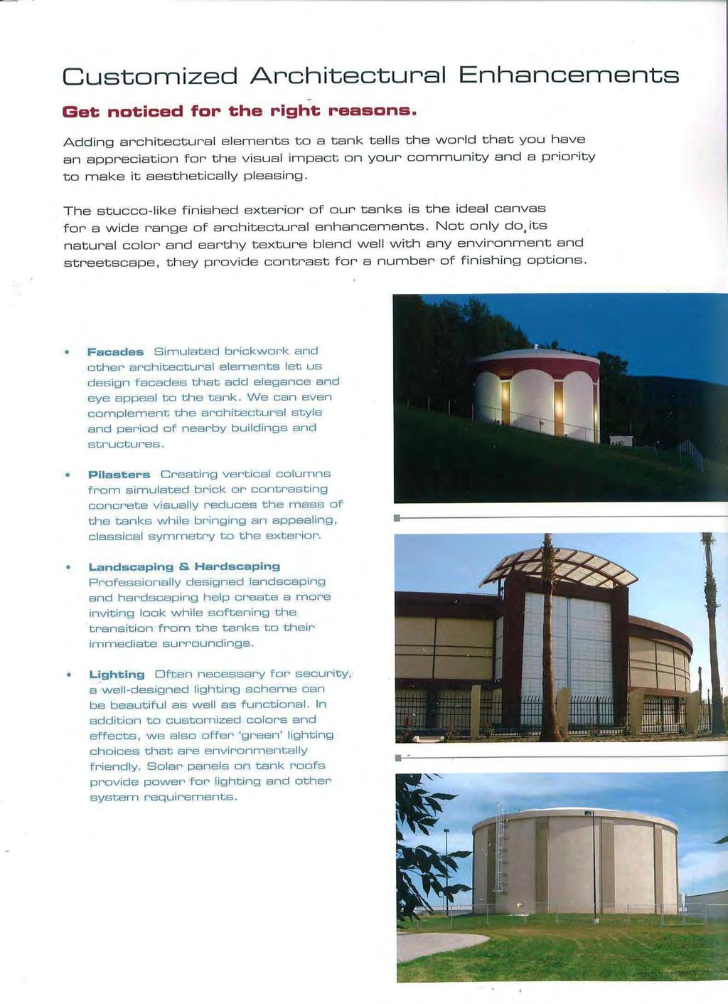
79
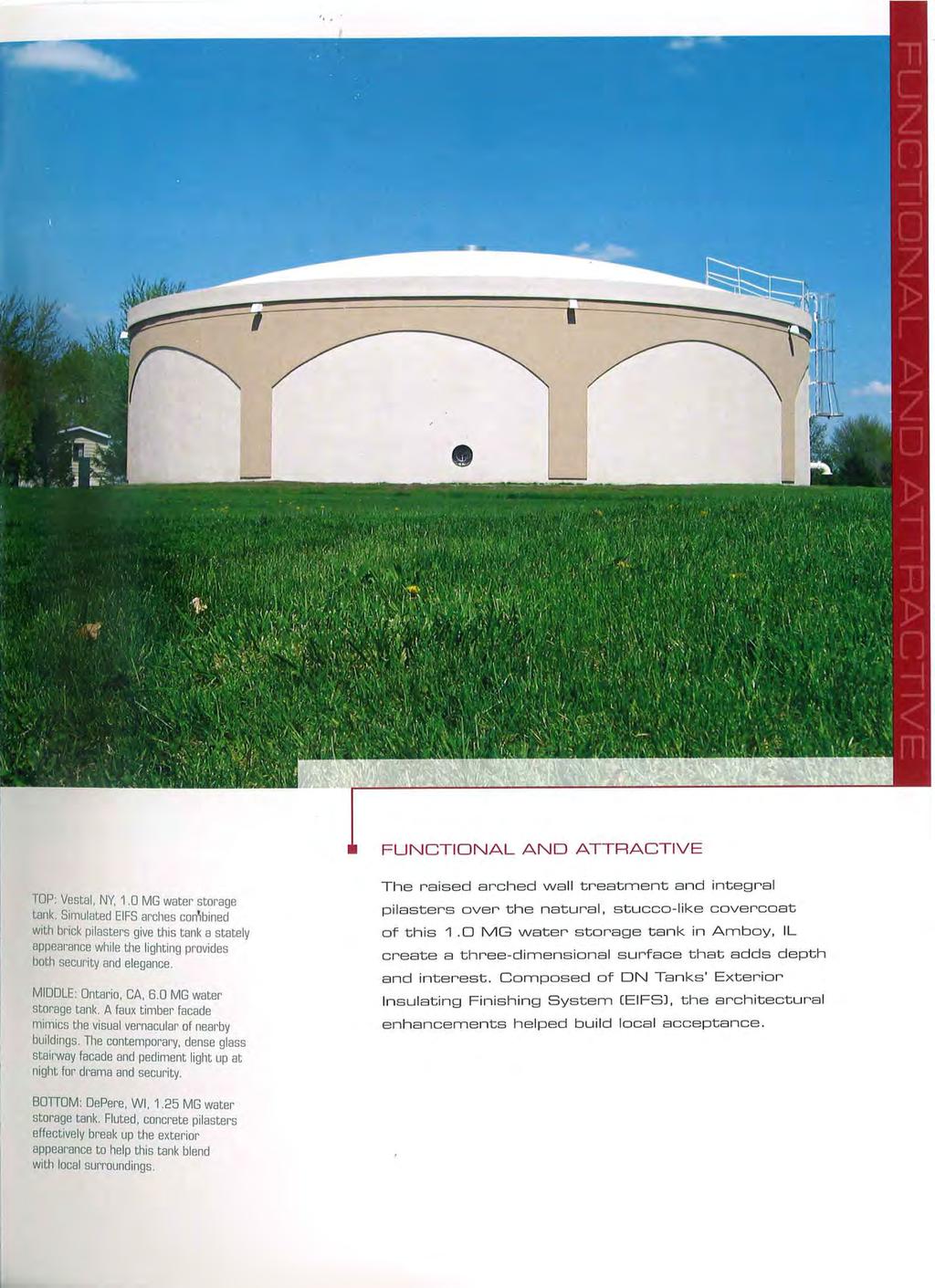
80

81
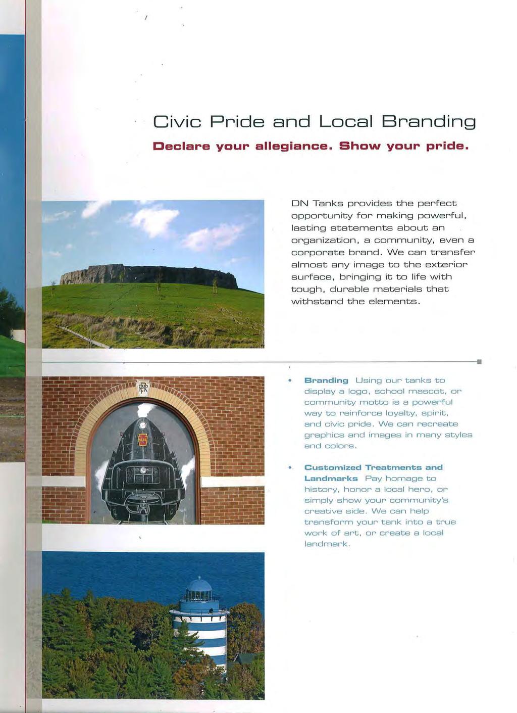
82
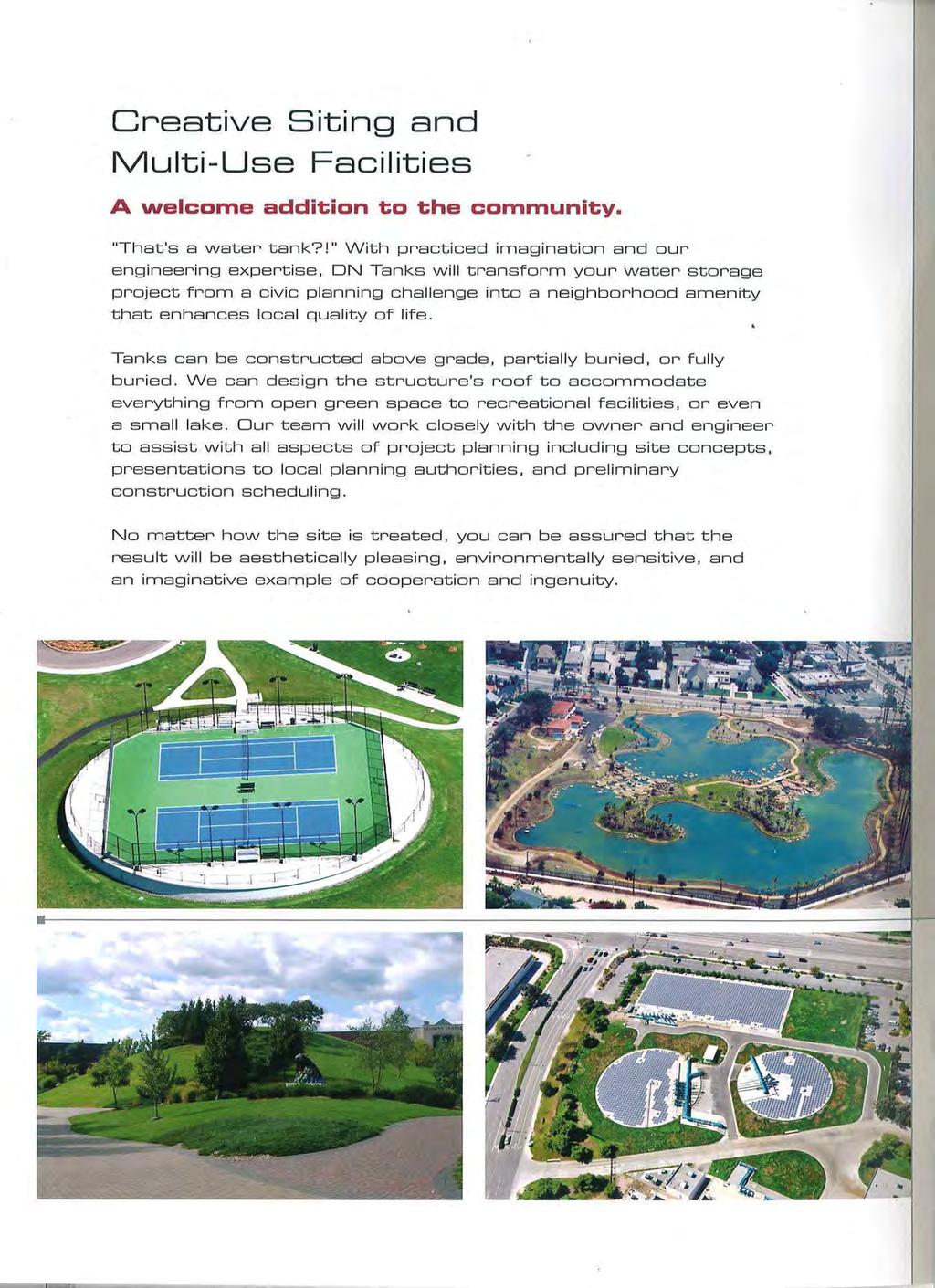
83

84
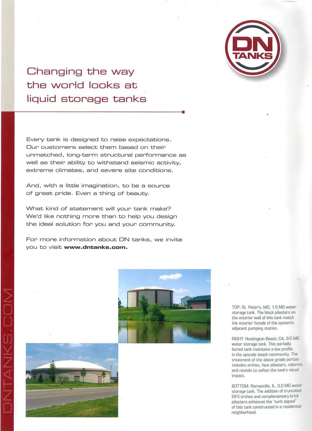
85
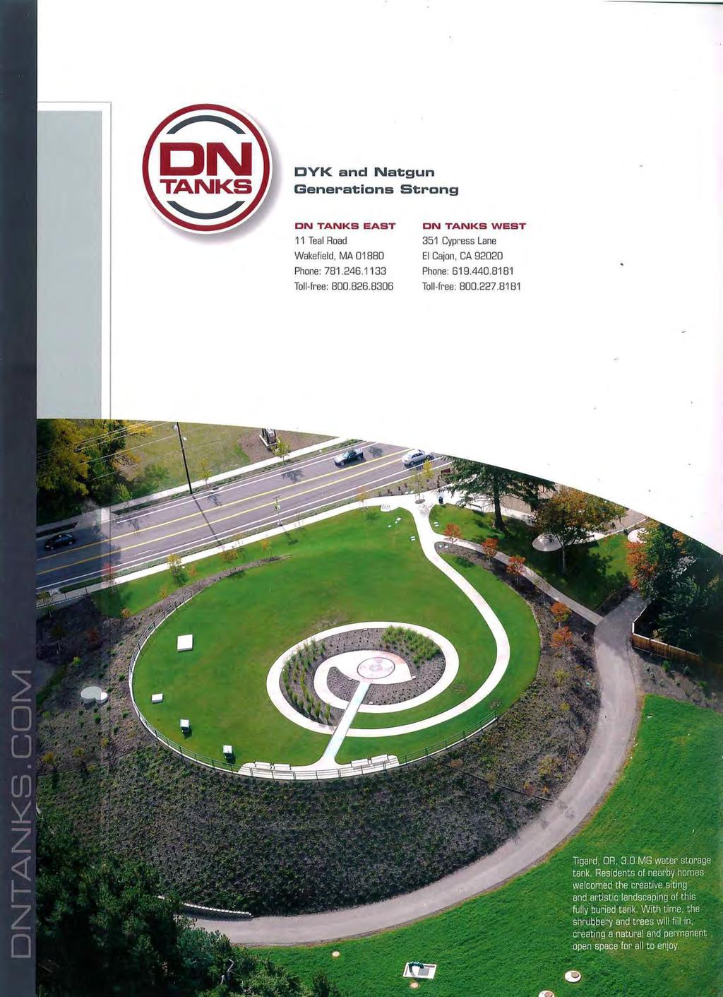
86


87 CONSTRUCTION PROCEDURES AWWA D110 Type I Prestressed Concrete Tanks

88 Site Preparation Floor & Footings Wall Construction Roof Options Vertical Prestressing Abrasive Blasting Circumferential Prestressing Advanced Technology Automated Shotcrete Appurtenances Tank Rendering Tank Gallery


89 DURABILITY FOR GENERATIONS TO COME At DN Tanks, we understand that a liquid storage tank is a critical component of infrastructure that serves a variety of storage needs, such as a community s potable water source, fire suppression source, an important step in the treatment of wastewater, a consistent source of recycled water, as well as many other uses. Each of these tanks are instrumental to the communities they serve. DN Tanks prestressed concrete storage tanks are individually designed with a full structural analysis to meet specific project needs. Quality, durability, and efficiency are ensured through specially trained and skilled field crews, advanced prestressing technology, and professional project management. Over 50 years of experience are ingrained into each AWWA D110 Type I prestressed concrete tank. Our years of commitment and focus in the prestressed concrete tank industry have cultivated expertise in engineering, estimating, project management, and construction. From project development and design assistance to construction and prestressing, DN Tanks dedicated team is ready to provide support services to ensure a successful tank project. We measure success by our lasting partnerships with clients and communities. KEY ATTRIBUTES OF DN TANKS AWWA D110 TYPE I PRESTRESSED CONCRETE TANKS Tank Capacities - from 40,000 gallons to 50 million gallons (MG) and above Custom Dimensions - water heights from 8 to over 100 and diameters from 25 to over 400 Siting Options - at grade, partially buried, differentially backfilled (hillsides), fully buried (with multi-use capabilities) Seismic Resilience - proven performance through Loma Prieta, Nisqually and Northridge earthquakes to name a few Enhanced Ductility - anchored flexible base and roof connections Bi-axial Wall Compression - provides longevity, durability and liquid tightness Best Long-term Value - coatings aren t required thus eliminating routine maintenance costs and down-time burdens Reinvesting in the Local Economy - use of materials, labor and equipment from within the community Enhanced Water Quality - concrete inherently insulates, keeping liquids at a more consistent temperature 1


90 SITE PREPARATION A properly prepared subgrade is essential to tank construction. Before the structural tank design begins, a licensed geotechnical engineer prepares a site specific geotechnical report. The report provides design parameters that include bearing capacity, anticipated settlements, seismic criteria, and recommended subgrade and foundation preparation. Subgrade preparation for each tank is completed in accordance with the civil site plans and the site specific geotechnical report Piping connections that penetrate through the floor (e.g. inlet, outlet, overflow, etc.) are encased in underslab concrete pipe blocks A waterstop is incorporated between the floor and pipe block to ensure a liquid tight connection Wall and roof pipe penetrations can be easily incorporated 2


91 FLOOR & FOOTINGS A typical prestressed concrete tank floor consists of the following features: A cast-in-place, highly-reinforced, concrete membrane floor with a slight upward slope to the center allows for drainage Monolithic or large section pours limit joints to improve tank performance and achieve construction efficiency A thickened perimeter wall footing to transmit the concentrated wall loads to the subgrade beneath A permanent PVC waterstop at all joints for water tightness Seismic base restraint cables are developed into the perimeter footing to account for site specific seismic loading Structural observation is performed by a Registered Engineer prior to the concrete pour Experienced field crews place the concrete and ensure it is vibrated, screeded, and finished to meet the project specifications 3

92 CAST-IN-PLACE WALL CONSTRUCTION Prestressed concrete places steel in tension and concrete in compression, allowing for both materials to resist forces in their ideal states. The corewall is designed to account for project specific parameters and loadings. A typical tank corewall consists of a 10 minimum uniform thickness. For larger capacity tanks, walls may be thicker and tapered on the inside face to accommodate increased loads. FEATURES OF AN AWWA D110 TYPE I WALL Enhanced Operational and Seismic Performance Anchored flexible base connection between the floor and wall (similar to a base isolation system) enhances ductility and reduces bending moments from hydrostatic, thermal, and seismic forces, allowing these structural elements to act independently Seismic base restraint cables anchored into the footing extend into the corewall, providing load transfer during a seismic event Quality Control Circumferential wall forms curved to the specific tank radius are equipped with equally spaced pour windows to enhance quality control, reduce overall drop height, and allow ease of access for concrete placement and vibration Walls are poured full height in up to 50 wide circumferential sections Rebar congestion is significantly reduced, promoting more efficient inspection and concrete placement Liquid Tightness and Durability Vertical prestressing threadbars cast in the wall provide vertical compression and minimize vertical bending moments caused by differential temperature and dryness conditions Horizontal joints are eliminated and vertical joints are minimized to provide superior water tightness All construction joints incorporate permanent PVC waterstops 4


93 5
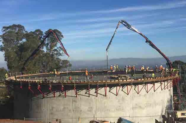
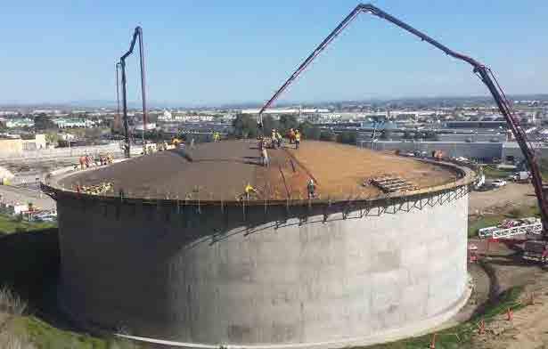
94 6


95 ROOF OPTIONS Prestressed concrete tanks can be designed with a variety of roof options. FLAT ROOF FEATURES Low profile cast-in-place, two-way flat slab roof minimizes visibility Option to bury or accommodate multi-use structures such as parks, recreation facilities, pump stations, etc. on the tank roof An anchored flexible wall/roof connection allows for thermal expansion of the roof slab while also providing seismic restraint Evenly spaced concrete columns, designed with drop panels and footings, support the roof and transfer the corresponding loads A slight upward slope to the center, matching the floor, provides drainage DOME ROOF FEATURES A clear-spanning concrete dome with no interior supports or obstructions can easily accomodate various equipment needs Typical dome height is 10% of the tank diameter Continuous reinforcement is incorporated in both radial and circumferential directions Circumferential prestressing applied at the dome ring places the dome in permanent compression 7


96 VERTICAL PRESTRESSING AWWA D110 Type I tanks incorporate vertical prestressing threadbars within the wall to provide vertical compression and counteract bending. Features include: High-strength steel threadbars are either 1 ¼ or 1 ¾ diameter depending on corewall thickness Threadbars are equipped with a screwed-on nut anchor at the top and bottom to eliminate stress concentrations Each threadbar is housed inside of a rigid PVC pipe to allow for proper installation A hydraulic ram is used to tension the threadbars after the concrete walls are poured Threadbars are tensioned to 137 kips or 173 kips for the respective diameter, with a tight force tolerance of 1.5% Force and elongation recordings are electronically and instantaneously produced for each vertical threadbar, documenting the applied stress After tensioning, threadbars are pressure grouted from the bottom up with a two-part epoxy to achieve a fully bonded system and corrosion protection 8


97 ABRASIVE BLASTING Prior to starting circumferential prestressing and shotcrete operations, DN Tanks advanced abrasive blasting system roughens the exterior corewall surface. System features include: Automated hydroblasting applies water at a high pressure of up to 40,000 psi to etch the wall to a precise roughened finish, providing a superior bonding surface An automated system reduces jobsite hazards, optimizes construction schedule and provides a consistent finish Hydroblasting is environmentally friendly as it requires very low water usage and eliminates dust 9

98 CIRCUMFERENTIAL PRESTRESSING Circumferential prestressing is the heart of the tank structure, counteracting the liquid load and placing the tank wall in 200 psi residual compression. DN Tanks significant industry advancements includes the automated machine application of tensioned, hot-dip galvanized, diameter 7-wire strand. By placing the strand in tension, and thereby the concrete wall in compression, the prestressed concrete tank incorporates both materials in their ideal states. The mechanical prestressing system allows application of a consistent prestressing force of 14,950 pounds with a tight tolerance of 1.5% of MUS. This greatly exceeds the AWWA minimum standard accuracy of 7% of the applied force. Strand is tensioned to 70% of MUS, placing the wall in permanent bi-axial compression to withstand the varying operational hydrostatic loads, as well as thermal and seismic dynamic loads. BENEFITS OF STRAND-WRAPPING: Improved accuracy & efficiency Tighter force tolerance Electronic spacing & recording Fewer splices Increased shotcrete bond Greater safety factor 10


99 ADVANCED TECHNOLOGY DN Tanks state-of-the-art circumferential prestressing equipment is able to perform multiple sophisticated tasks with one simple, automated, quality-controlled unit. In-line calibration and stress monitoring are utilized to provide complete accuracy in every step of the process. ELECTRONIC MONITORING & CONTINUOUS RECORDING Continuous electronic recording and instantaneous self-correcting force application are essential to ensure the proper stress is applied to the prestressing steel. The prestressing steel places the concrete into permanent compression and resists all hydrostatic loads. It is imperative that the stress is applied accurately. The automated system offers: Computerized, continuous electronic force readings for the highest quality control In-line calibration allowing for instantaneous control of the force applied A record of the force readings submitted to the Owner, providing confidence that the most critical part of the hydrostatic resistance has correctly been applied 11


100 AUTOMATED SHOTCRETE The advanced technology of the automated shotcrete process is proven to preserve the integrity of DN Tanks structures by providing corrosion protection and a permanent bond. FEATURES OF AUTOMATED SHOTCRETE Control of numerous variables such as uniform distance, angle, and applied thickness on large surface areas ensure complete encapsulation of the prestressing strand as well as a proper bond to the corewall Wet-mix shotcrete applied from a nozzle mounted on a mechanized tower travels at a controlled uniform speed and path A minimum final shotcrete cover of 1.5 inches, built up in multiple layers 12


101 APPURTENANCES Prestressed concrete tanks can accommodate a variety of accessories, such as roof and wall access hatches, interior and exterior ladders, vents, safety railings, level sensing equipment, or specialized security hardware. Our experienced team can help recommend and install appurtenances to meet specific project requirements. 13


102 1 PVC Waterstop 2 Elastomeric Wall-Base Bearing Pad 3 Tank Foundation 4 Vertical Prestressing Threadbars Housed in PVC Pipe Cast-in-Place Concrete Corewall 12 6 Seismic Base Restraint Cables 7 Continuous Circumferential Reinforcing 8 Ø 7-Wire Galvanized Circumferential Prestressing Strand 9 Shotcrete Encasement 10 Roof Shear Can 11 Wall Shear Can 12 Elastomeric Wall-Top Bearing Pad

103 Center Pin1 13 Base Unit and Engine1 7-Wire Galvanized Strand Reel1 Adjustable Tower1 Automated Shotcrete Arm and Nozzle1 Stressing Head1 Operations Cabin


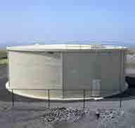
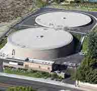
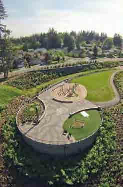


104 DN TANKS SHOWCASE
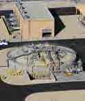


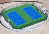

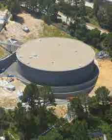

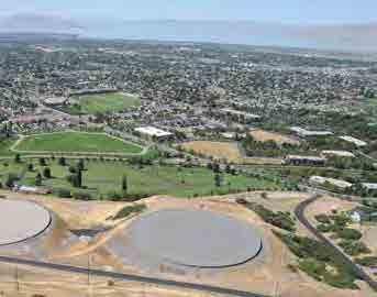
105

106 Generations Strong 351 Cypress Lane El Cajon, CA
Permanent Load Shifting Program
 1. Program Description Permanent Load Shifting (PLS) can help reduce system peak load by storing energy produced during off-peak period and shifting electricity use from on-peak to off-peak periods on
Chilled Water Plant Redesign
 17 Chilled Water Plant Redesign OVERVIEW The chilled water plant redesign includes the addition of a thermal energy storage system. This allows for economic and operational benefits for the facility by
WEST PLANT FEASIBILITY STUDY. The College of William & Mary EXECUTIVE SUMMARY (FINAL) APRIL 2013
 APRIL 2013") WEST PLANT FEASIBILITY STUDY EXECUTIVE SUMMARY (FINAL) The College of William & Mary APRIL 2013 RMF ENGINEERING, INC. CONSULTING ENGINEERS 5520 RESEARCH PARK DRIVE BALTIMORE, MARYLAND 21228 (410) 576-0505
WEST PLANT FEASIBILITY STUDY EXECUTIVE SUMMARY (FINAL) The College of William & Mary APRIL 2013 RMF ENGINEERING, INC. CONSULTING ENGINEERS 5520 RESEARCH PARK DRIVE BALTIMORE, MARYLAND 21228 (410) 576-0505
Large University Central Chiller Plant Design Considerations
 Carrier Engineering Newsletter Volume 5, Issue 3 Large University Central Chiller Plant Design Considerations Large campus chilled water plants have unique constraints and need careful evaluation for successful
D DAVID PUBLISHING. Optimizing Thermal Energy Storage Systems in the Hospitality Industry. 1. Introduction
 Journal of Energy and Power Engineering 8 (2014) 1991-2000 D DAVID PUBLISHING Optimizing Thermal Energy Storage Systems in the Hospitality Industry Patrick Wilkinson, Jesse Oshiro, Dean Perry and Helen
Applying Geothermal Technology for Large Scale Projects
 Jeff Urlaub, PE MEP Associates, LLC jeffu@mepassociats.com 715.832.5680 Engineering Future Focused Solutions Applying Geothermal Technology for Large Scale Projects Breakout Session Category (e.g. Residential)
CHILLED WATER THERMAL ENERGY STORAGE NEW MEXICO
 CHILLED WATER THERMAL ENERGY STORAGE NEW MEXICO HELLO Do you own a Thermal Energy Storage Tank? Energy Storage Energy is stored during off-peak periods, then distributed during peak periods. Examples of
Optimizing Central Chilled Water Systems
 Optimizing Central Chilled Water Systems OPTIMIZING CENTRAL CHILLED WATER SYSTEMS kent.peterson@p2seng.com 1 O P T I M I Z I N G C E N T R A L C H I L L E D W A T E R S Y S T E M S Kent W. Peterson, PE,
Xavier University of Louisiana
 Annual Savings Report Year 2 May 1, 2012 to April 30, 2013 July 2013 For Marion Bracy Vice President Xavier University Facilities Planning 1 Drexel Drive New Orleans LA 70125 (504) 520 1056 Submitted By
Section 2: Estimating Energy Savings and Incentives
 Section 2: Estimating Energy and Incentives 2.1 Estimating Energy and Incentives... 2 2.2 Customized Measures - Estimation Software... 2 2.2.1 AC&R I - High Efficiency Chiller... 4 2.2.2 AC&R I - Split/Packaged
Project Name: Example Building OFPC Project No.: 12345
 Energy Impact Statement Project Name: Example Building OFPC Project : 12345 Building Description and Assumptions: The design professional shall provide a brief narrative describing various building related
INCENTIVE ESTIMATOR HVAC USER GUIDE CONTENTS FLORIDA CUSTOM INCENTIVE PROGRAM
 INCENTIVE ESTIMATOR HVAC USER GUIDE FLORIDA CUSTOM INCENTIVE PROGRAM CONTENTS 1. Getting Started... 2 2. Measure Tool Description... 3 2.1. Appropriate Use of the Tool... 3 2.2. Applicable Types of Air
Ground-Coupled Heat Pump And Energy Storage
 Ground-Coupled Heat Pump And Energy Storage By Ed Lohrenz, Member ASHRAE; and Sergio Almeida, P.Eng., Member ASHRAE Ground-coupled heat pump (GCHP) systems consume less purchased energy than an HVAC system
SGM Engineering, Inc.
 SGM Engineering, Inc. 1. What is a typical Central Energy Plant consists of? BAS controls, chillers, pumps, cooling towers, electrical distribution, piping, chemicals, heating systems, and generators.
Thermal Energy Storage
 This article was published in ASHRAE Journal, June 2013. Copyright 2013 ASHRAE. Posted at www.ashrae.org. This article may not be copied and/or distributed electronically or in paper form without permission
CHILLED WATER DISTRIBUTION SYSTEM
 Campus-Wide System: A campus-wide central chilled water system has been developed in recent years and is being expanded to serve additional cooling loads as need arises and opportunity affords. This system
EnergyPro Building Energy Analysis. Single-story School Building
 EnergyPro Building Energy Analysis Single-story School Building EnergyPro Building Energy Analysis for a single-story school bulding Project Scope The purpose of the EnergyPro energy model was to evaluate
Characteristics of Energy Consumption by building type of a U.S. Navy Installation in Hot and Humid Climate
 Purdue University Purdue e-pubs International High Performance Buildings Conference School of Mechanical Engineering 216 Characteristics of Energy Consumption by building type of a U.S. Navy Installation
Mechanical Redesign. Existing System: The following schematic was devised below.
 Mechanical Redesign Existing System: The mechanical system explained in the existing conditions was simulated on an energy modeling system call equest. This program was used because of its strong detailed
Green Data Center CRYOGEL Ice Ball Thermal Storage
 Green Data Center CRYOGEL Ice Ball Thermal Storage Victor J. Ott, P.E. CRYOGEL, San Diego, CA Tuesday, March 1, 2011 4:30 5:30 PM, ACC, Room 207B Copyright Cryogel 2001 Telephone (858) 457-1837 Email:
Fifteen Year Plan for Energy Efficiency and Conservation Projects
 Fifteen Year Plan for Energy Efficiency and Conservation Projects Presented to the Board of Trustees of the Northeastern Ohio Universities Colleges of Medicine and Pharmacy, December, 2008, in accordance
Gregory W. Stevens and Ronald K. Ishii, Alternative Energy Systems Consulting, Inc.
 A Study of Optimizing the System Integration of Combined Heat and Power (CHP) with Absorption Cooling for Cold Storage Applications: Design Considerations, Modeling and Life Cycle Costing Gregory W. Stevens
Chilled Beams. The new system of choice?
 Chilled Beams The new system of choice? Presented By: Kevin M. Pope P.E. Jason Leffingwell Hammel Green And Abrahamson, Inc. and Ken Bauer, P.E., LEED AP Butters-Fetting Co., Inc. History of Chilled Beams
FRIGI-TECH OIL SUPPLEMENT TEST GAMMA BIOLOGICALS, INC MANGUM ROAD HOUSTON, TEXAS. performed by:
 FRIGI-TECH OIL SUPPLEMENT TEST GAMMA BIOLOGICALS, INC. 3700 MANGUM ROAD HOUSTON, TEXAS performed by: ADAMS MECHANICAL SERVICES, INC. 235 CORTLANDT HOUSTON, TEXAS TEST DATES: JUNE 16, 1989 - SEPTEMBER 10,
North Grounds Boiler and Chiller Plant Replacement
 Presenters: Justin Callihan, UVA Chiller Plants Associate Director Joe Witchger, HGA Energy & Infrastructure Group North Grounds Boiler and Chiller Plant Replacement Agenda Project Requirements UVA North
The Impact of VISIONWALL High Performance Windows on the Northern Telecom Building in Ottawa, Ontario
 The Impact of VISIONWALL High Performance Windows on the Northern Telecom Building in Ottawa, Ontario Visionwall Technologies Inc. 14904-123 Avenue Edmonton, Alberta, Canada T5V 1B4 Tel: 403 451 4000 Fax:
UNIVERSITY OF CALIFORNIA, SAN DIEGO
 BERKELEY DAVIS IRVINE LOS ANGELES MERCED RIVERSIDE SAN DIEGO SAN FRANCISCO SANT A BARBARA SANT A CRUZ OFFICE OF THE ASSIST ANT VICE CHANCELLOR CAMPUS ARCHITECT- FACILITIES DESIGN & CONSTRUCTION TEL: (858)
SURNA Grow Facility: Systems Comparison - IEA
 SURNA Grow Facility: Systems Comparison - IEA May 2016 SURNA Grow Facility This analysis provides the projected energy and associated cost comparison between the Surna proposed facility in comparison to
20 Add Hookups for Temporary Generators & Boilers
 NEW CODE 20 Add Hookups for Temporary Generators & Boilers I. Summary Issue: Buildings with extended service disruptions can use electricity and heat from temporary emergency generators and boilers. It
Side-by-Side Field Comparison of New and Rebuilt CFC-Free Chillers
 Side-by-Side Field Comparison of New and Rebuilt CFC-Free Chillers Henry Lau and Gregg D. Ander, Southern California Edison A large electric utility in Southern California has performed side-by-side field
Chilled Water Plant Assessment & Criteria Design
 Chilled Water Plant Assessment & Criteria Design Prepared for: Cleveland Airport System November 14, 2016 PREPARED BY: 1100 Superior Avenue Cleveland, Ohio 44114 (216)681-2020 TABLE OF CONTENTS SECTION
ORIGINAL YEAR OF CONSTRUCTION NUMBER OF BUILDING STORIES 02/06/2013 BUILDING SURVEY DATE
 0067 1110 WEST GREEN STREET URBANA, ILLINOIS 61801 SYSTEM CONDITION INDEX.810 PRIMARY BUILDING USE BUILDING SURVEY TEAM BUILDING SYSTEM REPLACEMENT COST $ 18,640,900 OFFICE BUILDING GROSS SQUARE FEET 175,513
Optimizing Clean Energy Systems with Thermal Energy Storage and/or Turbine Inlet Cooling
 Optimizing Clean Energy Systems with Thermal Energy Storage and/or Turbine Inlet Cooling Dharam V. Punwani, President Avalon Consulting, Inc. John S. Andrepont, President The Cool Solutions Company The
2017 STRATEGIC ENERGY AND WATER ANNUAL REPORT
 2017 STRATEGIC ENERGY AND WATER ANNUAL REPORT 2 NC STATE UNIVERSITY Energy and water are among NC State s most necessary and costly expenses. For more than a decade, the university s campus-wide energy
Shippensburg University
 Shippensburg University 1871 Old Main Drive Shippensburg, PA 17257 Central Chilled Water System Evaluation Professional: Entech Engineering, Inc. 4 South Fourth Street P.O. Box 32 Reading, PA 19603 Telephone:
Submitted to. Texas A&M University - Kingsville The Texas A&M University System. Submitted by. Yeqiao Zhu John Bryant Dan Turner David Claridge
 ESL-TR-99/12-07 Report of Energy Efficiency Study and Metering/Utilities Profile for Electricity Deregulation at the Texas A&M University - Kingsville (TAMU-K) Kingsville, Texas Submitted to Texas A&M
Chilled Water Energy Savings Study
 1 Chilled Water Energy Savings Study Pressure Dependent Valve Sizing and Valve Authority Pressure Independent Valves (Mechanical and Electronic) Chilled Water System Design MIT Beta Site Study-Correcting
South Jefferson High School Huyett Road Charles Town, WV 25414
 Thesis Proposal Mechanical System Redesign Report Charles Town, WV 25414 Prepared for Dr. Jelena Srebric The Pennsylvania State University By Jonathon Gridley Friday, December 15, 2006 1.0 Table of Contents
Xavier Energy Initiative
 Xavier Energy Initiative By Ron Perkins Report of August Site Visit To paraphrase Blaise Pascal, if I had more time I would have written a shorter report. In deference to those who do not share my enthusiasm
Project Information. Measure Description
 Project Information Project ID#: CE07M016 Measure: Multiple Electric : 452,593 kwh, 8.84 kw, 39.26 kw Facility Type School Technology: Multiple Measure Description CH-1 - Chiller Plant Optimization and
Georgetown University New Science Center
 Georgetown University New Science Center Final Thesis Proposal PENN STATE UNIVERSITY Prepared For: Dr. William P. Bahnfleth Department of Architectural Engineering Prepared By: Kevin M Edstrom Mechanical
Rowan University Energy Management Optimization of our Central Chilled Water System
 Rowan University Energy Management Optimization of our Central Chilled Water System Presented at the 2014 IDEA Annual Campus Energy Conference Atlanta, GA FOUR PILLARS OF ROWAN ENERGY MANAGEMENT: GENERATION
LOUISIANA STATE UNIVERSITY COMPREHENSIVE & STRATEGIC CAMPUS MASTER PLAN. APPENDIX N - Campus Utilities Assessment Findings
 LOUISIANA STATE UNIVERSITY COMPREHENSIVE & STRATEGIC CAMPUS MASTER PLAN APPENDIX N - Campus Utilities Assessment Findings Louisiana State University Campus Master Plan Campus Utilities Introduction Based
A new application of an old idea
 Thermal Energy Storage A new application of an old idea As the second-most populated country on this planet, India s ever-growing demand for energy has shown no signs of dwindling. A clearly strained electricity
Central Chilled Water Plant Sustainable Design. By : George Berbari, CEO DC PRO Engineering
 . By : George Berbari, CEO DC PRO Engineering Design Broad Objectives: Most Design Point Energy Efficient. Cost effective. Smallest foot print. Most Energy Efficient based on Year Round Operational. High
Analysis and System Design of a Large Chiller Plant for Korea, with or without Thermal Storage
 Analysis and System Design of a Large Chiller Plant for Korea, with or without Thermal Storage Christine Levin HVAC Designer Flack + Kurtz Consulting Engineers, LLP New York, New York Peter Simmonds Director
HVAC Variable Speed Pump Control System Diversity
 Monday, July 9, 2018 HVAC Variable Speed Pump Control System Diversity Monday Morning Minutes by Norm Hall, July 9, 2018 HVAC variable speed pump control does not have to be complicated. Often times a
Cornell University Chilled Water Best Management Practices Program Annual Report -
 Cornell University Chilled Water Best Management Practices Program - 2014 Annual Report - Prepared by: Cornell University Facilities Services Energy and Sustainability Utilities Report Date: 30 January
Outline Chilled Water T Study AHU Coil Overview Cooling Overview Test Setup Data Analysis Findings Summary
 Improved Chilled Water Plant Performance with New Energy Valve (EV) Outline Chilled Water T Study AHU Coil Overview Cooling Overview Test Setup Data Analysis Findings Summary 6 December 2012 Boston Hotels
2. Chilled Water Storage: A 4.4-million gallon chilled water storage tank improves Cornell s ability to meet peak cooling needs.
 SECTION 018130 ENERGY MODELING GUIDELINES APPENDIX A Modeling the District Heating and Cooling Systems of Cornell University for LEED Projects PART 1: GENERAL 1.01 PURPOSE A. Cornell is continually improving
A. Cornell s district energy systems include the following components:
 SECTION 018130 ENERGY MODELING GUIDELINES APPENDIX A Modeling the District Heating and Cooling Systems of Cornell University for LEED Projects PART 1: GENERAL 1.01 PURPOSE A. Cornell is continually improving
Texas Tech University Energy Savings Program October 2011 Update
 Texas Tech University Energy Savings Program October 2011 Update The Texas Tech Energy Savings Update is being submitted in accordance with Governor s Executive Order RP 49, Electric Conservation by State
Central Utilities at UNL: NU Corp & Development of Thermal Energy Storage (TES) at UNL East Campus
 at UNL East Campus") Central Utilities at UNL: NU Corp & Development of Thermal Energy Storage (TES) at UNL East Campus Big Ten and Friends Mechanical & Energy Conference U of Nebraska-Lincoln October 15, 2012 Before NU Corp
Central Utilities at UNL: NU Corp & Development of Thermal Energy Storage (TES) at UNL East Campus Big Ten and Friends Mechanical & Energy Conference U of Nebraska-Lincoln October 15, 2012 Before NU Corp
Matt Gudorf UCI Energy Manager
 Matt Gudorf UCI Energy Manager UNIVERSITY OF CALIFORNIA, IRVINE Comprehensive research university 22,216 Undergraduate Students $330 million sponsored research 27 lab buildings operating 24/7 ~7.5 Million
Level II - Whole Building Interval Electric Data with Tenant Plug Load System
 Level II - Whole Building Interval Electric Data with Tenant Plug Load System 1. Overview and Scope This specification describes the capabilities and data requirements for equipment or service providers
Science & Engineering Building I,
 Science & Engineering Building I, UC Merced UC Merced The University of California at Merced (UC Merced) is one of the first new research universities to be developed in the 21st Century. UC Merced aims
A HYBRID MONITORING-MODELING PROCEDURE FOR ANALYZING THE PERFORMANCE OF LARGE CENTRAL CHILLING PLANTS
 A HYBRID MONITORING-MODELING PROCEDURE FOR ANALYZING THE PERFORMANCE OF LARGE CENTRAL CHILLING PLANTS Ricardo Troncoso, P.E. Senior Engineer ACR Engineering, Incorporated 97 South Congress Avenue Austin,
Persistence Tracking in a Retro-commissioning Program
 Persistence Tracking in a Retro-commissioning Program Mike Eardley Architectural Energy Corporation Synopsis The persistence of energy savings and electrical demand reductions created by retrocommissioning
Commercial Retro-Commissioning Program Manual for 2015 SECTION 1
 Commercial Retro-Commissioning Program Manual for 2015 SECTION 1 Introduction The Commercial Retro-Commissioning Program (RCx) is designed to achieve demand and energy savings in commercial facilities.
ENERGY AUDIT REPORT MINIMUM REQUIREMENTS
 ENERGY AUDIT REPORT MINIMUM REQUIREMENTS Energy Audit Reports must contain the following: 1) Eligibility Criteria: a) Evidence demonstrating that the eligibility criteria were met. 2) Participant Information:
The ESP Handbook. Chapter 15 Obtaining Consumer Usage and Metering Information. Version 7.0 February 1, 2017
 The ESP Handbook Chapter 15 Obtaining Consumer Usage and Metering Information Version 7.0 February 1, 2017 SCE is committed to providing timely and accurate information to its customers or their authorized
This paper will discuss applications of an ice slurry generator that has been in production since The
 ICE SLURRY GENERATOR By Kirby P. Nelson, P.E. Presented at the IDEA Conference San Antonio, Texas June, 1998 Used with permission. ABSTRACT This paper will discuss applications of an ice slurry generator
CONSTRUCTION REQUIREMENTS
 CONSTRUCTION REQUIREMENTS Note: The buildings on the UCCS campus are divided into two categories: General Fund and Auxiliaries. General Fund Buildings include academic and administrative functions. Auxiliary
Chilled Water Loop Optimization. Kazimir Gasljevic Richard Dewey Sandro Sanchez
 Chilled Water Loop Optimization Kazimir Gasljevic Richard Dewey Sandro Sanchez WHAT WE STARTED WITH: LOOP OUTLINE: WHAT WE STARTED WITH: LOOP OUTLINE: - Justification for the loop WHAT WE STARTED WITH:
The Island University. A Campus of The Texas A&M University System Corpus Christi, Texas
 ! The Island University A Campus of The Texas A&M University System Corpus Christi, Texas This document was prepared to comply with the Governor s Executive Order RP49 - October 27, 2005 relating to energy
EnergyPro Building Energy Analysis. Nine-story Office Building
 EnergyPro Building Energy Analysis Nine-story Office Building EnergyPro Building Energy Analysis for an office building Project Scope The purpose of the EnergyPro energy model was to evaluate the energy
MENIFEE VALLEY CAMPUS MASTER PLAN DRAFT EIR MT. SAN JACINTO COMMUNITY COLLEGE DISTRICT. Appendices
 MENIFEE VALLEY CAMPUS MASTER PLAN DRAFT EIR MT. SAN JACINTO COMMUNITY COLLEGE DISTRICT Appendices Appendix J Utility Systems Data February 2017 MENIFEE VALLEY CAMPUS MASTER PLAN DRAFT EIR MT. SAN JACINTO
BOARD OF TRUSTEES OCTOBER 13, 2014
 Measure E BOARD OF TRUSTEES OCTOBER 13, 2014 FACILITIES UPDATE Measure Q 1 RECENTLY COMPLETED PROJECTS Santa Ana College Perimeter Site Improvements Building G Renovation Artesia Street Improvements Property
Comprehensive Energy Master Plan and Reallocation of Boiler 6 Bond Proceeds
 Comprehensive Energy Master Plan and Reallocation of Boiler 6 Bond Proceeds Timeline (Attachment 1): 2005 Budget Bill (HEA 1001,section 244,b) included $1.5 million for A&E/Permitting 2007 Budget Bill
Retrocommissioning Investigation Report
 Continuous Optimization for Commercial Buildings Program Retrocommissioning Investigation Report March 22, 2013 Prepared for: Thompson Rivers University International Building BC Hydro #:COP10-353 Prism
Gerald R. Ford Museum
 Gerald R. Ford Museum Grand Rapids, Michigan Executive Summary Building and Plant Energy Analysis Report: Part I Brendan J. Cullen The Pennsylvania State University AE Senior Thesis Mechanical Option September
Walter Reed National Military Medical Center Bethesda, MD
 Walter Reed National Military Medical Center Bethesda, MD Technical Report Two: Building and Central Plant Energy Analysis Prepared For: Dr. James D. Freihaut Prepared By: Justin Herzing Date: 10/28/09
STANFORD UNIVERSITY MEDICAL CENTER FACILITIES RENEWAL AND REPLACEMENT PROJECT UTILITIES AND SERVICES
 Revised 3/10 STANFORD UNIVERSITY MEDICAL CENTER FACILITIES RENEWAL AND REPLACEMENT PROJECT UTILITIES AND SERVICES This section contains the preliminary information for utility services to the following
Management Committee December 3, Johnson County Community College Retrocommissioning Report
 Johnson County Community College Retrocommissioning Report Management Committee December 3, 2014 What is Retrocommissioning? Retrocommissioning is a systematic process to improve an existing building s
Energy Reduction Strategy Through 2020
 Through 2020 Revised: August 2017 Executive Summary Auburn University is a land, sea and space grant university established in 1856. The university consists of 11,629,000 square feet on 1,840 acres and
Big Batteries that Enhance Turbine Inlet Cooling Systems
 Big Batteries that Enhance Turbine Inlet Cooling Systems Guy Frankenfield, PE (972) 823-3300 Guy.Frankenfield@dntanks.com www.dntanks.com Sponsored by: February 13, 2013; 1 PM (U.S. Central Time) http://www.meetingzone.com/presenter/default.aspx?partcec=414
CHAPTER/REGIONAL TECHNOLOGY AWARD - SHORT FORM
 CHAPTER/REGIONAL TECHNOLOGY AWARD - SHORT FORM 1. Category (Check one and indicate New or Existing, if applicable) Commercial Buildings New or Existing Institutional Buildings: Educational Facilities New
Cornell University Chilled Water Best Management Practices Program 2015 Annual Report
 Cornell University Chilled Water Best Management Practices Program 2015 Annual Report Prepared by: Cornell University Facilities Services Energy and Sustainability Utilities Report Date: 26 January 2016
UC Irvine Energy Efficiency Energy Storage Energy Optimization. Matt Gudorf CEM, LEED AP Assistant Director Energy, Engineering, and Inspection
 UC Irvine Energy Efficiency Energy Storage Energy Optimization Matt Gudorf CEM, LEED AP Assistant Director Energy, Engineering, and Inspection Quick Facts Established in 1965 Comprehensive Research University
I - 15 CORRIDOR CAMPUS MASTER PLAN DRAFT EIR MT. SAN JACINTO COMMUNITY COLLEGE DISTRICT. Appendices
 I - 15 CORRIDOR CAMPUS MASTER PLAN DRAFT EIR MT. SAN JACINTO COMMUNITY COLLEGE DISTRICT Appendices Appendix J Utility Systems Data August 2017 I - 15 CORRIDOR CAMPUS MASTER PLAN DRAFT EIR MT. SAN JACINTO
Coppin State University Physical Education Complex - Technical Report 2
 Coppin State University Physical Education Complex - Technical Report 2 Building and Plant Energy Analysis Report Kaylee M Damico Advisor: Dr. Jelena Srebric Location: Baltimore, MD Table of Contents Contents
District Cooling Sustainable Design. Presented by George Berbari CEO of DC PRO Engineering
 2016 District Cooling Presented by George Berbari CEO of DC PRO Engineering District Cooling Brief History & Future Central Chilled Water plants existed in the Middle East as early as the 1960 s. Few examples
ABSTRACT I. INTRODUCTION II. METHODS AND MATERIAL
 2017 IJSRSET Volume 3 Issue 2 Print ISSN: 2395-1990 Online ISSN : 2394-4099 Themed Section: Engineering and Technology Chiller and AHU Design for A commercial Usage S M Azfar Hashmi, Mirza Muneer Baig,
Energy Efficiency Baselines for LABORATORIES. PG&E s Customized New Construction and Customized Retrofit Incentive Programs.
 Energy Efficiency Baselines for LABORATORIES PG&E s Customized New Construction and Customized Retrofit Incentive Programs October 1, 2010 Funded By: Written By: 427 13 th Street Oakland, CA 94612 510.663.2070
Thermal Energy Storage (TES) Systems in Educational Facilities
 Systems in Educational Facilities") Thermal Energy Storage (TES) Systems in Educational Facilities Presenter: Larry M. Stoff, PE, LEED AP BD+C Director of Mechanical Engineering What We Will Talk About Today 1. What is a TES system 2. Types
Thermal Energy Storage (TES) Systems in Educational Facilities Presenter: Larry M. Stoff, PE, LEED AP BD+C Director of Mechanical Engineering What We Will Talk About Today 1. What is a TES system 2. Types
University of Southern California Main Campus Plant Energy use reduction of 49% compared to previous plants and control strategies.
 Foreword Most chiller based systems save energy when compared to packaged cooling equipment, but they waste a substantial amount of energy compared to their optimized state of operation. On an annual basis,
George Mason University
 2009 UTILITY MASTER PLAN UPDATE FINAL SUBMISSION George Mason University JULY 2009 RMF ENGINEERING, INC. CONSULTING ENGINEERS 5520 RESEARCH PARK DRIVE BALTIMORE, MARYLAND 21228 (410) 576-0505 Fax: (410)
Building Load and Energy Estimates Analysis. Instructor: Dr. Mumma. October 28, Thesis Building Sponsor s: INOVA Fairfax Hospital
 David Peterson Penn State AE, Mechanical INOVA Fairfax Hospital The INOVA Heart Institute David J. Peterson Mechanical Option Mechanical Technical Report #2b The INOVA HEART INSTITUTE AT INOVA Fairfax
Chilled Water Plant Statement of Capabilities
 ENGINEERED ENERGY SOLUTIONS INC. 166 West Ed Avenue Somerville, NJ 08876 Phone: (908) 252-3800 Fax: (908) 252-3801 Chilled Water Plant Statement of Capabilities Table of Contents S E C T I O N 1 History
CONTINUOUS COMMISSIONING OF SALT LAKE COMMUNITY COLLEGE SOUTH CITY CAMPUS
 CONTINUOUS COMMISSIONING OF SALT LAKE COMMUNITY COLLEGE SOUTH CITY CAMPUS Song Deng, P.E. and Dan Turner, P.E., Ph.D., Energy Systems Laboratory, Texas A&M University System, College Station, Texas Jim
MicroGrids and CHP. September 8, 2016
 MicroGrids and CHP Facilities Operations & Building Services Utilities Operations and Energy Management Chris Tietjen, Central Utility Plant & Cogen Facility Engineer September 8, 2016 UCONN Storrs Campus
Retro-commissioning and on-going commissioning 23 November 2016
 Retro-commissioning and on-going commissioning 23 November 2016 1 CONTENTS 1. Needs for Retro-Commissioning (RCx) 2. Retro-Commissioning (RCx) Definition and Scope 3. Briefing of RCx Process 4. Alternative
(For ASllRAE Staff Use Only)
") ASHRAE TECHNOLOGY AWARDS APPLICATION FORM (Page 1) APPLICATION MUST BE COMPLETE TO BE CONSIDERED FOR JUDGING (Required for Society-Level Competition) 18 (For ASllRAE Staff Use Only) I. Identification (0
ASHRAE TECHNOLOGY AWARDS APPLICATION FORM (Page 1) APPLICATION MUST BE COMPLETE TO BE CONSIDERED FOR JUDGING (Required for Society-Level Competition) 18 (For ASllRAE Staff Use Only) I. Identification (0
A Complex Organism. A Revitalized Campus
 Home A Complex Organism By Steven C. Severini, P.E., LEED AP September 28, 2006 The Centers for Disease Control and Prevention (CDC) is undergoing significant changes at its Atlanta campuses. With many
Auburn Facilities Energy Reduction Plan
 Auburn Facilities Energy Reduction Plan Revision 2: May 2012 Overall Plan: Auburn University Facilities will work to reduce energy usage, utility consumption, energy costs, and the University s carbon
3 Mechanical System Redesign
 3 Mechanical System Redesign 3.1 Considered Alternatives The MAC building offered many opportunities to change the existing design and explore an alternative different than the solution the original design
Capitol Area Development Study
 Capitol Area Development Study Thermal Utility Master Plan Austin, Texas November 17, 2017 Prepared for the Texas Facilities Commission and Page by: HDR Engineering, Inc. a Texas Registered Engineering
Economic Feasibility Study. September 12, 2008
 Economic Feasibility Study September 12, 2008 VERSION HISTORY Version Date Author Change Description 1.0 9-8-2009 Siemens SBT Initial creation. 1.1 9-9-2008 Siemens SBT 1.2 9-12-2008 Siemens SBT Deleted
Simulation of Source Energy Utilization and Emissions for HVAC Systems. A report ASHRAE TC 6.9 in response to the 991-TRP workstatement.
 Simulation of Energy Utilization and Emissions for HVAC Systems A report ASHRAE TC 6.9 in response to the 991-TRP workstatement submitted by Douglas T. Reindl, Ph. D, P.E. Director of Research University
Teague Research Center
 Continuous Commissioning Report for the Teague Research Center Building #445 Submitted to: Utilities Energy Office Physical Plant Department Texas A&M University Prepared by: Energy Systems Laboratory