Building Enclosure & Energy Performance of Log & Timber Homes
|
|
|
- Maria Hicks
- 6 years ago
- Views:
Transcription
1 EGH Building Enclosure & Energy Performance of Log & Timber Homes Testing and Modeling Summary " Douglas Fir Baseline Framed Improved Enclosure Improved Enclosure & Mechanical High Performance Enclosure 70 Abbotsford Kamloops Whistler Prince George Fort Nelson High Performance Enclosure & Mechanical PREPARED FOR: BC Log and Timber Frame Home Market Expansion Project SUBMITTED BY RDH Building Engineering Ltd. 224 West 8th Avenue Vancouver, BC V5Y 1N5 Canada PROJECT NUMBER DATE May 10, 2013 R:\ Log Wall\ Building Science Consulting Services\Report\ Research Report\ RPT Log Homes Code Compliance FINAL_.doc
2 Acknowledgements This report was prepared by RDH Building Engineering Ltd. with funding provided by the BC Log Home and Timber Frame Building Sector Market Expansion & Development Project and support and guidance from the BC Log and Timber Building Association (BCLTBIA). The BC Log Home and Timber Frame Building Sector Market Expansion & Development Project was funded by a consortium of partners: Western Economic Diversification Canada The Pine Beetle Epidemic Response Branch of the Ministry of Jobs, Tourism and Skills Training Southern Interior Development Initiative Trust Cariboo-Chilcotin Beetle Action Coalition Southern Interior Beetle Action Coalition The Cariboo-Chilcotin Beetle Action Coalition (CCBAC) acted as the lead financial and contract manager for the Project. RDH Building Engineering Ltd. gratefully acknowledges both the project funders and the BCLTBIA and its member companies for providing the funding and support to complete this testing and report RDH Building Engineering Ltd.
3 Table of Contents Acknowledgements 1. Introduction Laboratory Air Leakage and Water Penetration Testing Test Methodology Log Wall Assembly Construction Test Protocol Test Results Whole Building Air-tightness Testing Test Methodology Test Results Summary Energy Performance of Log Homes BC Building Code Requirements for Energy Efficiency Thermal Performance of Log Walls Archetypes for Energy Modeling Baseline House Inputs Energy Efficiency Measures Energy Simulation Results for Archetype Energy Simulation Results for Archetype Energy Simulation Results for Archetype Thermal Mass Radiant Barrier Coatings Conclusions Appendix A Laboratory Air Leakage and Water Penetration Test Reports Appendix B Whole House Air Leakage Test Results Appendix C Complete Energy Simulation Results RDH Building Engineering Ltd.
4
5 1. Introduction Log and timber home construction is a highly valued and traditional form of home building. Although log homes have provided effective housing for centuries, recent changes in the building code have made it difficult for home builders and building officials to confirm compliance with some of the prescriptive and performance based building code requirements. The building code primarily addresses stick-built wood-frame housing and although building codes do allow for alternative compliance paths, these paths are not well established for log homes. RDH was retained by the log and timber home building industry to help address three key aspects of performance and compliance with the building code: l Water Penetration Control: The current BC Building Codes exempts log walls from the rainscreen wall requirement on the basis that rainscreen walls are only required when cladding is present and log walls are not clad in the traditional sense. However, this interpretation is not uniformly understood and appropriately administered by building officials in all jurisdictions. In addition, there is a desire to proactively demonstrate water penetration control properties and develop appropriate code language for log wall assemblies that can be utilized in building codes. Strategies such as reduction in exposure with overhangs, mass wall characteristics of the logs, effective lateral joint design, and assembly interface and penetration details all contribute to effective water penetration control. l l Air-tightness: The current BC Building Code generally requires that air-tightness be incorporated into the full building enclosure. It provides examples of air-tightness strategies for various types of assemblies and lists air permeance for some materials but does not specifically address log home construction. Air-tightness is an important aspect of both rain penetration control and energy efficiency performance. It is therefore important that data exists regarding log wall air permeance and that overall log home air leakage can be controlled and quantified. Appropriate building code language for log homes also needs to be developed. Energy Performance: The building code provides prescriptive insulation (thermal conductivity) levels for walls and other elements of the building enclosure in Part 10. Log homes are currently exempt from these requirements but this will not be the case when the new requirements become mandatory at the end of These prescriptive requirements are difficult to meet with traditional log wall construction because walls do not contain a specific insulation layer with good thermal resistance properties. Whole building energy modeling can be utilized to demonstrate equivalent energy performance with the code mandated whole building baseline performance. Compliance is achieved through trade-offs in performance between thermal performance of walls, roofs, windows, as well as efficiency of mechanical systems and inclusion of air-tightness performance. Laboratory testing was performed on four test wall specimens to assess the water penetration resistance and air-tightness of log home wall assemblies. The intent of the testing was to identify performance issues that need to be addressed through changes in assembly construction and/or detailing. Chapter 2 provides a summary of this aspect of the project. To assess the overall air-tightness of log homes, air-tightness testing was completed for four houses: three log homes and one timber frame home. Air-tightness tests were completed to determine overall air leakage rates of typical log homes, and to identify areas for improvement in construction detailing that could lead to more air-tight houses. Chapter 3 provides a summary of this aspect of the project. To assess energy performance, whole building energy simulations were completed to determine how log homes can meet code with energy efficiency improvements to offset the lower wall insulation values. Computer energy simulations were completed for three archetype log homes. Chapter 4 provides a summary of this aspect of the project. Appendices provide more detailed information regarding all three aspects of the project RDH Building Engineering Ltd. PAGE 1 OF 50
6


7 2. Laboratory Air Leakage and Water Penetration Testing Laboratory testing was undertaken to determine the basic air-tightness and water penetration resistance characteristics for typical log wall assemblies. Additional testing was undertaken to identify opportunities for improved performance, and suggest areas where additional testing may be warranted Test Methodology Testing of the log home wall assemblies was undertaken using the testing facility at the Cascadia Windows Ltd. s manufacturing facility in Langley, BC (Fig.2.1 and Fig.2.2). The Cascadia facility is capable of testing specimens as large at 16 x 12. This apparatus can be used to perform water penetration resistance testing, air leakage testing, and structural testing. Fig.2.1 Front view of Cascadia Windows in-house Test Wall Fig.2.2 Rear view of Cascadia Windows in-house Test Wall The construction of the interface between the edges of the log wall assemblies, the perimeter mounting buck, and the test wall is critical to create air and water tight boundary conditions. If this interface is not constructed correctly, unintended air and water ingress may occur, affecting the results of the testing. Following completion of testing on the first two modules, additional information was distributed to the builders regarding the construction of the test modules and perimeter mounting bucks. After completion of testing on the first two modules it was hypothesized that venting the lateral groove to the exterior would moderate the pressure difference between the lateral grooves and the exterior thereby reducing the driving force for water penetration and improving the water penetration resistance of the wall assemblies. The venting means that the most air-tight part of the wall assembly within the lateral groove is at the interior seal. This location is where the majority of the air pressure drop will occur under wind driven rain conditions. Similarly, the air pressure drop between the exterior and the lateral groove is reduced or eliminated because of the direct venting path into the lateral groove. Water penetration requires a source, a hole, and a driving force. At the outside surface of the log wall the venting eliminates the primary driving force (air pressure differential due to the wind) because of the moderation effect of the venting, and therefore water penetration is unlikely to occur. At the inside, air-tight surface of the wall and lateral joint the wind induced air pressure difference does occur but since there is no water present, water penetration is unlikely to occur. This approach to controlling water penetration is generally known as rainscreen and is utilized in many building enclosure assembly designs. The third and fourth modules included provisions to vent the lateral groove to the exterior as part of supplementary testing in an attempt to demonstrate pressure moderation potential for the lateral groove. The lateral grooves were vented with two oversized tie-down rod chases that ran vertically the height of the test wall and exited to the exterior side of the wall on RDH Building Engineering Ltd. PAGE 3 OF 50


8 a diagonal in the bottom log (Fig.2.3). The walls were tested with the diagonal holes sealed (unvented) and open (vented) (Fig.2.4). Fig.2.5and Fig.2.6are elevations of Modules 3 and 4 indicating the location of the pressure taps. The pressure taps are used to measure the pressure difference between the lateral grooves and exterior. Fig.2.3 Rendering of how the lateral groove and venting of the log home test wall was achieved. Fig.2.4 Log home test wall with plug in the vent holes sealed. Fig.2.5 Elevation of Module 3 indicating location of the 5 pressure taps and threaded tie-down rods with oversized chases Fig.2.6 Elevation of Module 4 indicating location of the 8 pressure taps and threaded tie-down rods with oversized chases 2.2. Log Wall Assembly Construction A total of four log wall assemblies were tested: l l l Module 1: hand crafted, scribed fit, Douglas Fir logs with a log diameter of 14, and EMSeal gasket either side of the lateral groove (Fig.2.7). Module 2: mountain pine beetle killed manufactured d-logs, 5 ½ wide by 7 ½ tall, double tongue and lateral groove with Loctite PL Premium Polyurethane Construction Adhesive (Fig.2.8). Module 3: squared Red Cedar logs, 11 ½ by 11 ½, with a tongue and lateral groove with a p-gasket at either side (0) PAGE 4 OF 50 RDH Building Engineering Ltd


9 l Module 4: hand crafted, scribed fit, Douglas Fir logs with a log diameter of 14, and p-gasket at either side of the lateral groove (0). Each of the modules was constructed by a different log home builder, following instructions regarding overall specimen size and configuration provided by RDH. Refer to the attached test reports in Appendix A for further information regarding the constructions of the log wall assemblies. Fig.2.7 Module 1 Fig.2.8 Module RDH Building Engineering Ltd. PAGE 5 OF 50


10 Module 3 Module Test Protocol The test wall at Cascadia Windows was used to determine the air and water tightness of the completed assembly in general conformance ASTM E283 and ASTM E331, respectively. During the water testing, all panels were tested at 0, 150, 300 and 500 Pa unless the amount of water ingress prevented further testing. A full round of testing was performed twice on each of test modules 3 and 4, one round with the lateral grooves not vented and one round with the lateral grooves vented to the exterior. Refer to the test reports in Appendix A for further information regarding the setup and the type of equipment used to perform the testing Test Results Testing of the first two modules was performed October 7 and 8, 2011 and the testing of the last two modules was performed December 14 and 15, Table 2.1 provides a summary of the test results. Table 2.2 and Table 2.3 provide the pressure difference measured in both Modules 3 and 4 respectively. It is believed that the water ingress observed in Module 1 occurred as a result of water ingress between the edges of the log wall assembly and the perimeter mounting buck, and as such these results are likely not representative of the actual water penetration resistance characteristics of the wall assembly PAGE 6 OF 50 RDH Building Engineering Ltd
11 Table 2.1 Summary of test results. Module 1 Module 2 Lateral Grooves not Vented Module 3 Module 4 Lateral Grooves Vented Lateral Grooves not Vented Lateral Grooves Vented Test Results at 75 Pa Water Test Results L/s. m L/s. m L/s. m L/s. m L/s. m L/s. m 2 0 Pa FAIL 0 Pa PASS 0 Pa PASS 0 Pa PASS 150 Pa FAIL 300 Pa FAIL 150 Pa PASS 300 Pa PASS 500 Pa PASS 700 Pa PASS 150 Pa PASS 150 Pa PASS 150 Pa PASS 150 Pa PASS 300 Pa PASS 300 Pa PASS 300 Pa PASS 300 Pa PASS 500 Pa PASS 500 Pa PASS 500 Pa PASS 500 Pa PASS Table 2.2 Pressure difference at pressure tap locations in Module 3 Test # Lateral Grooves Vented or Not Vented Test ΔP (pa) (Interior to Exterior) ΔP (pa) at Pressure Tap Locations (Lateral Groove to Interior) Not vented Vented Vented 0 NA NA NA NA NA 4 Vented NA 5 Vented Vented Not vented NA NA NA NA 8 Not vented NA NA NA NA 9 Not vented NA NA NA NA RDH Building Engineering Ltd. PAGE 7 OF 50
12 Table 2.3 Pressure difference at pressure tap locations in Module 4 Test # Lateral Grooves Vented or Not Vented Test ΔP (pa) (Interior to Exterior) ΔP (pa) at Pressure Tap Locations (Lateral Groove to Interior) Not vented Vented Vented Vented 0 NA NA NA NA NA NA NA NA 5 Vented NA NA NA NA 6 Vented NA NA NA NA 7 Vented NA NA NA NA 8 Not vented NA NA NA NA 9 Not vented NA NA NA NA 10 Not vented NA NA NA NA Air leakage Table A (1) and (2) of the 2006 British Columbia Building Code, suggests that to be considered an air barrier a material should have an air leakage rate of less than 0.05 L/s-m 2 at 75 Pa when interior relative humidity is greater than 55%. All tested modules have an air leakage rate of much less than 0.05 L/s-m 2 at 75 Pa which exceeds (better) the building code requirements or recommendations Water ingress No water ingress was observed within the field of the wall, except for Module 1 where the water ingress observed was likely a result of poor construction of the test module perimeter rather than representative of a he performance of the wall itself. The current practice of using gasketing within the lateral grooves appears to be effective in controlling water penetration within the field area of the wall Pressure Moderation Venting of the lateral grooves to the exterior was effective in achieving some pressure moderation and therefore it is possible to utilize a pressure moderation, or rainscreen approach to further limit the risk of water penetration at lateral joints in log wall assemblies. At higher test pressures the moderation effect was less complete. Better pressure moderation may be achieved by increasing the size of the holes connecting the lateral grooves to the exterior, larger vertical holes through the logs, use of less gasketing material, or the creation of larger lateral air spaces. As no water ingress was observed during testing of both Modules 3 and 4 even without venting, it was not possible to fully determine if pressure moderation is critical to performance under specific conditions, or if it simply provides reduced risk of water penetration under all situations PAGE 8 OF 50 RDH Building Engineering Ltd
13 3. Whole Building Air-tightness Testing The control of air leakage through the building enclosure is important in order to reduce energy consumption for heating and cooling. Air leakage occurs through unintentional holes through the building enclosure; at interface joints between components and assemblies penetrations (mechanical and electrical). The air-tightness of a house is measured by conducting a blower door test. For this test, the house is pressurized and the air leakage rate of the house is calculated based on the fan speed and the pressure difference between inside and outside. Section 3.1 provides additional details on the blower door testing methodology. Air-tightness of homes is typically reported in units of air changes per hour, or ACH. The 2012 BCBC does not have a maximum air-tightness requirement for houses, though lower ACH rates will help achieve a better EnerGuide rating which is being proposed as part of the building compliance strategy for log homes. Houses are required to undergo air-tightness testing in order to receive an EnerGuide rating. The R-2000 standard (a voluntary Canadian standard for energy efficient houses) requires an air-tightness of 1.5 ACH measured at 50 Pa (ACH 50 ). The Passive House standard requires an airtightness of 0.6 ACH 50. Test results from a log home in Denmark were obtained, where the house achieved 0.87 ACH 50, indicating that low air-tightness ratings are possible with log home construction. Blower door tests were conducted for three log homes and one timber frame house to assess the overall air-tightness of log and timber frame homes, and to identify air leakage paths and areas for improvement. In addition to blower door tests, smoke testing and infrared thermography were used to more clearly identify air leakage paths for each house. The following sections detail testing methodology and results from the four homes that were tested Test Methodology The air-tightness testing procedure followed the methodology for the EnerGuide for Houses air-tightness test. This methodology follows the standard CGSB M86 Determination of the Air-tightness of Building Envelopes by the Fan Depressurization Method. The EnerGuide test requires a modification to the CGSB standard; that the house must be tested as operated (under normal operating conditions, without sealing intentional openings such as dryer vents, combustion air inlets, and fireplace chimneys). The EnerGuide test also includes an additional step that is not in the CGSB standard; testing the level of house depressurization with all of the exhaust appliances operating to check whether an appliance may be spilling combustion products. However, this test was not completed on the four log and timber frame houses since combustion spillage was not a focus of this study. The test procedure for the EnerGuide blower door test to obtain an ACH rating is as follows: 1. Prepare the house for the test: close all exterior windows and doors, turn off exhaust fans, open all interior doors, etc. 2. Connect tubing to the exterior of the blower door and extend it away from the house to the outside. 3. Install the blower door apparatus in an exterior doorway. This consists of a door made of fabric in a frame, or a solid panel, that covers the door opening, plus a fan that sits in the opening of the door cover (Fig.3.1). 4. Connect the manometer (pressure measuring instrument) and tubing to the fan airflow meter. 5. Ensure all gauges are set to zero. 6. With the fan off, seal the fan opening and record the inside-outside pressure difference. This gives a baseline measurement of the inside-outside pressure difference, particularly to determine the effect of wind. 7. Uncover the fan, turn the fan on and increase the speed until the inside-outside pressure difference reaches 50 Pa. 8. Record the airflow or fan pressure at different pressure readings, starting at 50 Pa and working down in 5 Pa increments RDH Building Engineering Ltd. PAGE 9 OF 50


14 Fig.3.1 Blower door test apparatus viewed from the exterior (left) and the interior (right). 9. Turn off the fan, seal the fan opening and record the inside-outside pressure difference. This is done to ensure the wind has not changed significantly since the start of the test, and to ensure the gauges are reading correctly. The pressure difference should be within 3 Pa of the initial reading. 10. To check air leakage locations, turn the fan high enough to obtain a 30 Pa reading, and walk around the house with a smoke pencil to view areas where smoke entered through the enclosure. In addition to the EnerGuide test procedure, additional qualitative testing was completed by pressurizing the house and using smoke and infrared thermography to locate air leakage sources. After the EnerGuide pressurization test was complete, the fan was turned around in order to pressurize the house. The house was pressurized to 50 Pa, and smoke was generated inside the house using a theatrical fog machine (Fig.3.2). Areas where smoke was visible at the outside were recorded as air leakage paths. Fig.3.2 Theatrical fog machine smoke testing apparatus. Following the smoke testing, the house was left pressurized for one hour. An infrared camera was used to take photos of the house from the exterior. These photos were compared to infrared photos of the house while it was depressurized to further assist in identifying air leakage paths PAGE 10 OF 50 RDH Building Engineering Ltd
. The house is one-storey with a cathedral ceiling and a heated crawlspace. Heating is provided by a gas furnace in the crawlspace.")

15 3.2. Test Results The following sections provide a summary of the air-tightness test results for each of the four homes that were tested. Complete test reports are provided in Appendix B Test House #1 The first test house is a log home in 100 Mile House, BC, built in 2003 (Fig.3.3). The house is one-storey with a cathedral ceiling and a heated crawlspace. Heating is provided by a gas furnace in the crawlspace. The house contains logs of four different species: spruce, pine, fir and cedar. The logs were measured to have a diameter of approximately 14. Air sealing of the log walls was completed by sealing joints at the exterior. Crawlspace walls had 2 XPS insulation inside of the concrete wall and acoustically sealed polyethylene placed over the insulation Fig.3.3 Air-tightness test house #1, 100 Mile House, BC. Floor plans were not available for this house; however the area was measured on site. The floor area of the house is approximately 1,110 sf. The total enclosure surface area (including crawlspace and slab) is approximately 3,870 sf, and the total volume (including the heated crawlspace) is approximately 17,500 ft 3. The depressurization test resulted in an air-tightness of 2.82 ACH 50. This corresponds to an equivalent leakage area of 86.3 in 2 at 10 Pa, or 46.3 in 2 at 4 Pa. Smoke testing while the house was depressurized showed air leakage around the windows and doors, particularly at operable windows (Fig.3.4). At windows, leakage appeared to occur both around the frame (between the window and the rough opening), as well as between the sash and the frame at operable units. A particularly large amount of leakage was observed at the back door to the house. Smoke testing while the house was pressurized showed air leakage around the windows and doors, as well as through the corner joints in the log wall (Fig.3.5). A significant amount of leakage was seen through the corner joint RDH Building Engineering Ltd. PAGE 11 OF 50
 thermography photos were taken of the house during depressurization and during pressurization.")

 but not in the depressurization photo (where cold")

16 Fig.3.4 Smoke infiltration observed at operable windows during smoke pencil testing from the exterior under depressurization. Fig.3.5 Smoke infiltration observed at corner joints and exterior door during smoke testing from the interior under pressurization. Infrared (IR) thermography photos were taken of the house during depressurization and during pressurization. It is important to compare the photos under the two conditions to identify air leakage paths rather than thermal bridges ; areas with less insulating value that can also show up as warm points in the thermal images. If an area shows up as a warm point in both the depressurization and pressurization photos then it is likely not an air leakage path but rather a thermal bridge. However if an area shows up as a warm point in the pressurization photo (where warm indoor air is being forced out of the house) but not in the depressurization photo (where cold outdoor air is being drawn into the house), then the point is likely an air leakage path. Infrared thermography photos need to be carefully interpreted for this reason. Fig.3.6 and Fig.3.7 show IR images during depressurization and pressurization. As with smoke testing, the IR images showed air leakage occurring at windows and doors, and through log wall corner joints PAGE 12 OF 50 RDH Building Engineering Ltd
 and")

, showing air leakage through the")

17 Fig.3.6 IR photo of the door during depressurization (left) and pressurization (right), showing air leakage around the door during pressurization. Fig.3.7 IR photo of a joint during depressurization (left) and pressurization (right), showing air leakage through the joint during pressurization RDH Building Engineering Ltd. PAGE 13 OF 50
 with a cathedral ceiling and an insulated crawlspace. Heating is provided by electric baseboards.")

18 3.2.2 Test House #2 The second test house is a log home located in 100 Mile House, BC, built in 2003 (Fig.3.8). This house is two-storeys (onestorey plus loft) with a cathedral ceiling and an insulated crawlspace. Heating is provided by electric baseboards. The house contains Lodgepole Pine logs which were measured to have a diameter of approximately 14. Air sealing of the log walls was completed by sealing joints at the interior. Crawlspace walls had 2 XPS insulation inside of the concrete wall; though it was noted the insulation stopped approximately 2 short of the top of the crawlspace wall. Fig.3.8 Air-tightness test house #2, 100 Mile House, BC. The area and volume of this house were calculated from floor plans. The floor area of the house is approximately 1,100 sf (660 sf at the first floor plus a 440 sf loft). The total enclosure surface area (including crawlspace and slab) is approximately 3,270 sf, and the total volume (including the crawlspace) is approximately 13,400 ft 3. The depressurization test resulted in an air-tightness of 4.57 ACH 50. This corresponds to an equivalent leakage area of in 2 at 10 Pa, or in 2 at 4 Pa. Smoke testing using a smoke pencil while the house was depressurized showed air leakage at two operable windows (bathroom window and one first floor back window); no leakage was observed through the other fixed and operable windows. Smoke testing using a theatrical fog machine while the house was pressurized showed air leakage through the corner joints in the log wall and around operable windows (Fig.3.9) PAGE 14 OF 50 RDH Building Engineering Ltd
 and around operable windows (right) during smoke testing from the")
 thermography photos were taken of the house during depressurization and during pressurization.")

 and pressurization (right), showing air leakage during")
19 Fig.3.9 Smoke infiltration observed at corner joint (left) and around operable windows (right) during smoke testing from the interior under pressurization. Infrared (IR) thermography photos were taken of the house during depressurization and during pressurization. Fig.3.10, Fig.3.11 and Fig.3.12 show IR images during depressurization and pressurization. Fig.3.13, Fig.3.14 and Fig.3.15 show additional IR images taken during pressurization where no depressurization photo exists, but air leakage paths can still be identified. The IR images show air leakage occurring at windows, doors and joints. Fig.3.10 IR photo of a window during depressurization (left) and pressurization (right), showing air leakage during pressurization around the window frame and at joints between logs where the logs meet the window RDH Building Engineering Ltd. PAGE 15 OF 50


20 Fig.3.11 IR photo of the gable and roof overhang during depressurization (left) and pressurization (right), showing air leakage at the joint during pressurization. Fig.3.12 IR photo of the foundation (crawlspace) wall and log wall interface during depressurization (left) and pressurization (right), showing air leakage through the crawlspace vent during pressurization. Fig.3.13 Air leakage at windows and joints under pressurization PAGE 16 OF 50 RDH Building Engineering Ltd


21 Fig.3.14 Air leakage at second floor door and at roof overhang joints under pressurization. Fig.3.15 Air leakage at joints under pressurization RDH Building Engineering Ltd. PAGE 17 OF 50


22 3.2.3 Test House #3 The third test house is a timber frame house with traditional wood stud infill wall construction in Chase, BC (Fig.3.16). The building is new, and at the time of testing interior finishes were being completed. This house is split level, with the main floor (split) plus a loft and a walkout basement, and a cathedral ceiling (Fig.3.17). Heating is provided by a gas furnace and radiant floor heating in the basement. The house has a gas fireplace that was not yet operational. Fig.3.16 Air-tightness test house #3, Chase, BC. Fig.3.17 Cathedral ceiling and timber frame construction viewed from the inside of test house #3, Chase, BC. The area and volume of this house were calculated from floor plans. The floor area of the house is approximately 2,840 sf. The total enclosure surface area is approximately 6,730 sf, and the total volume is approximately 33,400 ft 3. The depressurization test resulted in an air-tightness of 1.43 ACH 50. This corresponds to an equivalent leakage area of 130 in 2 at 10 Pa, or 90 in 2 at 4 Pa. Note that although this house achieved a lower ACH 50 rate than the first and second test PAGE 18 OF 50 RDH Building Engineering Ltd

. Fig.3.18 Smoke infiltration observed at sliding glass door between IGU and frame (left) and at operable window between sash and frame (right) under depressurization.")

 thermography photos were taken of the house during depressurization and during pressurization. Fig.3.20, Fig.3.21, Fig.3.22 and Fig.3.23 show IR images during depressurization and pressurization.")
23 houses, the equivalent leakage area is larger than the previous two houses. This occurs because of the large volume of test house #3, which lowers the ACH 50 rate (i.e. air leakage occurs over a larger volume). Smoke testing using a smoke pencil while the house was depressurized showed air leakage at all of the operable windows, between the sash and the frame. Leakage was also observed at the top right corner of the sliding glass door between the IGU and the frame (Fig.3.18). Fig.3.18 Smoke infiltration observed at sliding glass door between IGU and frame (left) and at operable window between sash and frame (right) under depressurization. Smoke testing using a theatrical fog machine while the house was pressurized showed air leakage around the sliding glass door (Fig.3.19). No air leakage was observed at the framing or at fixed windows. Fig.3.19 Theatrical fog machine used for smoke testing at a corner of the house (left) and smoke leakage observed around the sliding glass door (right) under depressurization. Infrared (IR) thermography photos were taken of the house during depressurization and during pressurization. Fig.3.20, Fig.3.21, Fig.3.22 and Fig.3.23 show IR images during depressurization and pressurization. Fig.3.24 and Fig.3.25 show additional IR images taken during pressurization. The IR images show air leakage occurring at windows, doors, joints, and at the roof to wall interface RDH Building Engineering Ltd. PAGE 19 OF 50

, showing air leakage during")


24 Fig.3.20 IR photo of a sliding glass door during depressurization (left) and pressurization (right), showing air leakage during pressurization around the door frame. Fig.3.21 IR photo of the gable and roof overhang during depressurization (left) and pressurization (right), showing air leakage at joints during pressurization PAGE 20 OF 50 RDH Building Engineering Ltd


 and at the roof")

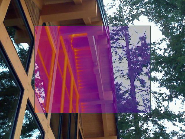
25 Fig.3.22 IR photo of a window during depressurization (left) and pressurization (right), showing air leakage at the corners during pressurization. Fig.3.23 IR photo of the roof to wall interface during depressurization (left) and pressurization (right), showing air leakage at this interface during pressurization. Fig.3.24 Air leakage at a vent (left) and at the roof to wall interface (right), both under pressurization RDH Building Engineering Ltd. PAGE 21 OF 50


26 Fig.3.25 Air leakage at the roof to wall interface, both under pressurization Test House #4 The fourth test house is a log home in New Westminster, BC, built in 2011 (Fig.3.26). This house is two-storeys plus a basement, with a cathedral ceiling. Heating is provided by a gas furnace as well as electric baseboards in the basement. The house also has a gas fireplace. The house is made from spruce logs which were measured to have diameters ranging from approximately 13 to 17. Joints between logs were gasketed. Fig.3.26 Air-tightness test house #4, New Westminster, BC. The area and volume of this house were calculated from floor plans. The floor area of the house is approximately 3,000 sf. The total enclosure surface area (including slab and ceiling areas) is approximately 4,400 sf, and the total volume (including the basement) is approximately 28,400 ft 3. The depressurization test resulted in an air-tightness of 6.43 ACH 50. This corresponds to an equivalent leakage area of in 2 at 10 Pa, or in 2 at 4 Pa. Smoke testing using a smoke pencil while the house was depressurized showed air leakage at operable windows and at the log wall corner joints (Fig.3.27). At the windows, significant leakage was observed at the operator hardware. Leakage PAGE 22 OF 50 RDH Building Engineering Ltd

.")

27 was also observed at the head and jamb between the frame and the rough opening, and between the sash and the frame of the operable unit. Fig.3.27 Smoke infiltration observed at corner joint during smoke testing from the interior under pressurization. Smoke testing was also performed using a theatrical fog machine while the house was pressurized. This testing showed significant leakage at various areas (Fig.3.28, Fig.3.29 and Fig.3.30). Leakage was observed around windows and doors (between the frame and the rough opening), at log wall corner joints, and at the roof soffit. Fig.3.28 Smoke leakage observed at log wall corner joint during pressurization RDH Building Engineering Ltd. PAGE 23 OF 50
 and at door (right) during")
 and at window jamb (right) during")


28 Fig.3.29 Smoke leakage observed at log wall corner joint (left) and at door (right) during pressurization. Fig.3.30 Smoke leakage observed at log wall corner joint (left) and at window jamb (right) during pressurization. Infrared (IR) thermography photos were taken of the house during depressurization and during pressurization; however, air leakage cannot be viewed from many of the images due to sun hitting the building affecting surface temperatures. Fig.3.31 shows IR images during depressurization and pressurization, where air leakage at the joint can be seen during pressurization PAGE 24 OF 50 RDH Building Engineering Ltd


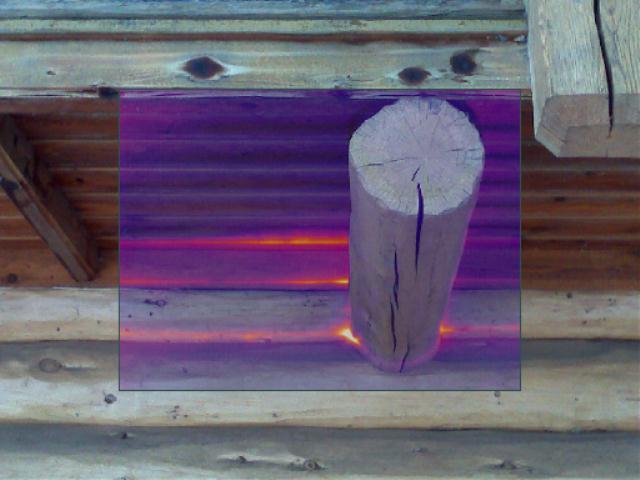
29 Fig.3.31 IR photo of a log wall corner joint during depressurization (left) and pressurization (right), showing air leakage during pressurization Summary Three log houses and one timber frame house were tested for whole building air-tightness. Table 3.1 provides a summary of the test results for the four houses. The timber frame house, achieved an ACH 50 rating of 1.43, below the R-2000 standard of 1.5. Areas for improvement identified included sealing at the roof to wall interface, corners, and more air-tight operable windows. The log homes tested had significant leakage at the log wall corner joints, as well as at window and door interfaces and at the roof to wall interface. The newest log house that was tested, which was built with gasketed joints between logs, resulted in the highest air leakage rate. Table 3.1 Summary of air-tightness testing results for depressurization test. Test House #1 Test House #2 Test House #3 Test House #4 Construction Type Log Log Timber Frame Log Year of Construction Log sealing approach Exterior Log Interface Sealed Interior Log Interface Sealed N/A Gasketed Air-tightness, ACH Equivalent leakage area at 10 Pa, in Equivalent leakage area at 4 Pa, in Air leakage observed during smoke testing and IR photos Operable windows, door, joints Operable windows, door, joints Operable windows and sliding glass doors, joints, roof to wall interface Operable windows and doors, joints, soffit RDH Building Engineering Ltd. PAGE 25 OF 50
30
31 4. Energy Performance of Log Homes 4.1. BC Building Code Requirements for Energy Efficiency BC Building Code The 2012 BC Building Code (BCBC) includes energy efficiency requirements for buildings in Part 10, Section 10.2 Energy Efficiency. Low-rise residential buildings are required to meet prescriptive insulation requirements for enclosure assemblies, or alternatively buildings can comply by achieving an EnerGuide rating of 77. The following is an excerpt from the 2012 BCBC on the energy efficiency requirements for low-rise residential buildings: Design 2) If a building is less than 5 storeys in building height, the parts of the building that are classified as Group C major occupancies shall be provided with thermal insulation that conforms to Table A or Sentence (3). a) between heated space and unheated space, exterior air and exterior soil, and b) between heating floor assemblies and heated space, unheated space, exterior air and exterior soil. 3) Thermal insulation required by Sentence (2) that does not conform to Table A shall Table 4.1 a) use energy computer modelling to achieve equivalent performance to the requirements in Table A. (see Appendix A), or b) achieving an EnerGuide Rating System rating of 77, verified by an EnerGuide Rating System energy advisor licensed by Natural Resources Canada to evaluate the energy efficiency of new houses. BCBC 2012 Table A Minimum Thermal Resistance of Insulation R SI, m2- C/W for Buildings of Residential Occupancy less than 5 Storeys in Building Height Building Assembly Value Required Value Required Value Required Less than 3500 Degree Days 3500 Degree to 4500 Degree Days More than 4500 Degree Days Attic Space(1) Roof Joist Assemblies (Cathedral Ceilings / Flat Roofs) Frame Walls(2) (including frame crawl space walls) Suspended Floors (framed) Suspended Floors (concrete slab) Foundation Walls (insulation to 600 mm below grade) Unheated Concrete Slabs on Ground at or above grade (insulation around edge of slab(3) and 500 mm vertical or horizontal from bottom edge of slab) Radiant Heating Slabs on Ground (insulation under all slab area and around edge of slab) Radiant Heating Suspended Floor Assembly Over Heated Area (insulation between heated floor and heated area below)(4) (1) The thermal resistance rating of attic space insulation may be reduced to value required for frame walls for a distance of RDH Building Engineering Ltd. PAGE 27 OF 50
32 a. 1.0 m from the exterior wall in buildings where the thermal resistance rating of the wall below is not required to exceed 3.5, or b. 1.5 m from the exterior wall in buildings where the thermal resistance rating of the wall below is not required to exceed (2) Stud/Frame type wall construction. This is not intended to apply to masonry, log or construction without a cavity. (3) The top edge of insulation between the slab edge and foundation wall may be protected with a pressure treated preserved wood filler strip not more than 50 mm thick. (4) Not applicable when heating elements or piping are located within a concrete topping on a suspended floor assembly or within an internally heated suspended slab. Although most log walls do not meet the prescriptive insulation requirements for frame walls, the code includes a note (note 2 above) that specifies this value does not apply to log wall construction. Log homes can still demonstrate compliance through the alternative path of computer energy modeling or EnerGuide rating EnerGuide Rating System The EnerGuide Rating System was established by Natural Resources Canada to rate the energy efficiency of houses in Canada. The system assigns ratings based on a scale of 0 to 100, where 100 represents a house that requires no purchased energy on an annual basis. Typical EnerGuide ratings according to the EnerGuide website are shown in Table 4.2. Note that the 2012 BCBC requires an EnerGuide rating of 77 if prescriptive enclosure insulation requirements are not met. Table 4.2 Typical EnerGuide ratings according to NRCan website. Type of House EGH Rating New House built to building code standards 65 to 72 New house with some energy efficiency improvements 73 to 79 Energy efficient new house 80 to 90 House requiring little or no purchased energy 91 to 100 EnerGuide ratings are determined by modeling a house in the energy simulation program HOT2000. This is a program provided by Natural Resources Canada that takes inputs regarding the geometry, enclosure, mechanical system, etc. of a house, and estimates the annual energy consumption for the given set of inputs. HOT2000 is used by EnerGuide energy advisors to determine the EGH rating of a house. HOT2000 is used for this study to assess the EGH rating and relative energy performance of typical log houses, compared to framed houses and log houses with energy efficiency improvements. The house geometry, enclosure details and mechanical details are entered into the program, and the program estimates the annual energy consumption of the house. To receive an EnerGuide rating a blower door test must also be performed when construction is complete to determine the actual air-tightness of the house. Three archetype log homes have been used for this study to create EnerGuide models and assess the energy performance of typical log homes compared to frame houses, and to investigate the impact of potential energy efficiency improvements Thermal Performance of Log Walls The thermal performance of walls and other building enclosure assemblies is typically specified in terms of an overall thermal resistance, measured in metric units of m 2 -K/W or imperial units of hr-ft 2 -F/Btu. Using metric units, this is typically denoted using R SI -value, versus R-value for imperial units PAGE 28 OF 50 RDH Building Engineering Ltd
33 The 2012 BCBC prescriptive insulation requirements include a minimum R-value of R SI -3.5 W/m 2 -K (R-20) for framed walls in locations with less than 4500 Heating Degree Days (HDDs), and R SI (R-22) in locations with more than 4500 HDDs. This would typically be met by using 2x6 framing filled with fibreglass batt insulation (high density batt to achieve R SI -3.85). The thermal performance of log walls depends on the thickness of the logs and the species of wood. ICC Standard on the Design and Construction of Log Structures includes calculated R-values for log walls. R-values are given based on the specific gravity of the species and average width, W L, of the logs. W L is defined as the average cross sectional area divided by the stack height (which is smaller than the average diameter of the log). The R-values given in ICC are calculated using W L (the calculation is given in Section ). Table 4.3 shows a selection of R-value per inch of wood from the standard ICC 400 (a property of the wood species). Table 4.3 ICC R-value per inch and R SI-value per mm of wood species. Log Species R-Value per inch (wood property) R SI -Value per mm (wood property) Western Red Cedar Red Spruce, White Fir, W. Spruce-Pine-Fir Black Spruce, E. Spruce-Pine-Fir, Eastern Softwoods, Eastern Spruce, Sitka Spruce, Western Softwoods Hem-Fir, Lodgepole Pine, Ponderosa Pine, Red-Canadian Pine Douglas Fir-Larch To confirm the R-value of log walls, two-dimensional heat transfer simulations of log walls were completed using the program THERM. THERM is a finite element analysis program used to calculate the effective R-value of building enclosure assemblies. This provides a more accurate R-value than a simpler calculation based on average width. The average width calculation may not correctly account for reduced heat loss at the joints (due to the non-linear nature of heat transfer), and therefore comparing the simulation results to ICC values will help assess the accuracy of this calculation. THERM simulations were completed for two wood species and four log sizes. The wood species Douglas Fir and Western Red Cedar were chosen since they represent a low and high R-value per inch wood species, respectively. A log diameter of 14 is typical based on discussions with BC log home builders, and therefore log diameters of 10, 14, and 18 were simulated for comparison. Each wall was simulated with a typical foam gasket joint and with an air space for comparison. Joint thicknesses were assumed to be 4, 5 and 6 for the 10, 14 and 18 diameter logs, respectively. The ICC inside and outside air film values were used in the THERM simulations. Fig.4.1 shows a sample log wall THERM simulation RDH Building Engineering Ltd. PAGE 29 OF 50


34 Fig.4.1 THERM simulation of log wall with foam gasket and air space. Fig.4.1 shows the results of the THERM simulations compared to the ICC R-values. Cases where the THERM simulations resulted in lower R-values than the standard values are bolded. The simulations of a joint with a foam gasket and air space provided lower R-values than in the ICC except for the 10 Western Red Cedar. With the joint full of foam, the 10 and 14 THERM simulations gave R-values higher than the standard values, however the 18 diameter simulations were lower than the standard R-values. Table 4.4 ICC and calculated R-values of log walls. Log Species and Size ICC R-Value, m2-k/w (hr-ft2-f/btu) [Table ] Calculated R-value, Joint with Gasket and Air Space, m2-k/w (hr-ft2-f/btu) Calculated R-value, Joint with Full Foam, m2-k/w (hr-ft2-f/btu) Douglas Fir, 10 diameter 1.47 (8.3) 1.44 (8.2) 1.51 (8.6) Douglas Fir, 14 diameter 2.02 (11.5) 1.94 (11.0) 2.08 (11.8) Douglas Fir, 18 diameter 2.59 (14.7) 2.24 (12.7) 2.40 (13.6) Western Red Cedar, 10 diameter 1.98 (11.2) 1.97 (11.2) 2.06 (11.7) Western Red Cedar, 14 diameter 2.75 (15.6) 2.62 (14.9) 2.85 (16.2) Western Red Cedar, 18 diameter 3.56 (20.2) 3.05 (17.3) 3.29 (18.7) 4.3. Archetypes for Energy Modeling Three archetype houses were modeled: a 1,200 sf two-storey house with a square floor plate and no basement, a 1,200 sf two-storey house with an L-shaped floor plate and a basement, and a large 2,400 sf two-storey house with a square floor plate and no basement. These archetypes were chosen to investigate a variety of typical house geometries, primarily large and small sizes and slab on grade or basement configurations PAGE 30 OF 50 RDH Building Engineering Ltd
. The house has a cathedral ceiling and does not have a basement.")


 and second floor plan (right)....................................................................................................................... 5197.")
35 4.3.1 Archetype 1 The first archetype is a two-storey log home with a floor area of approximately 1,200 sf (Fig.4.2 and Fig.4.3). The house has a cathedral ceiling and does not have a basement. The overall window to wall ratio of the house is 15% (including glazed doors). The first floor exterior walls are constructed from logs, and the second floor gable areas are assumed to be typical wood frame construction. The house also has second floor knee walls that are assumed to be framed construction. Fig.4.2 Archetype 1 front view (left) and back view (right). Fig.4.3 Archetype 1 first floor plan (left) and second floor plan (right) RDH Building Engineering Ltd. PAGE 31 OF 50
. The house has a cathedral ceiling and a basement. The overall window to wall ratio of the house is 18% (including glazed doors).")


36 4.3.2 Archetype 2 The second archetype is a two-storey log home with an above grade floor area of approximately 1,200 sf (Fig.4.4 and Fig.4.5). The house has a cathedral ceiling and a basement. The overall window to wall ratio of the house is 18% (including glazed doors). The first floor exterior walls are constructed from logs, and the second floor gable areas are assumed to be typical wood frame construction. The house also has second floor knee walls that are assumed to be framed construction. Fig.4.4 Archetype 1 front view (left) and back view (right). Fig.4.5 Archetype 2 first floor plan (left) and second floor plan (right) Archetype 3 The third archetype was created by doubling the footprint of the first archetype to create a larger house with a floor area of 2,400 sf, no basement and a rectangular footprint. The window to wall ratio of this archetype was kept constant at 15% PAGE 32 OF 50 RDH Building Engineering Ltd
37 4.4. Baseline House Inputs Table 4.5 shows the building enclosure, mechanical, and other inputs for the baseline house energy simulations in HOT2000. Building enclosure inputs are from the 2012 BCBC prescriptive requirements. Window U-values and mechanical system efficiencies are from the BC Energy Efficiency Act (EEA). Other inputs are standard EnerGuide assumptions. The baseline code compliant house was simulated with the above inputs, where all walls had the minimum code-compliant wall. Six log homes were simulated (where only the log wall R-value was changed compared to the code): two wood species and three log sizes. R-values were taken from ICC (shown in Table 4.4). Table 4.5 Baseline house inputs for energy simulations. Source Units <3500 HDD HDD >4500 HDD Building Enclosure Attic R-Value 1 BCBC m 2 -K/W Cathedral Ceiling R-Value BCBC m 2 -K/W Wall R-Value BCBC m 2 -K/W Suspended floors (framed) BCBC m 2 -K/W Door R-Value EEA m 2 -K/W Window U-Value EEA W/m 2 -K Window SHGC Typical Slab-on-grade (Unheated) (Insulation BCBC m 2 -K/W around edge of slab and 0.5 m vertical or horizontal from bottom edge of slab) Foundation Walls BCBC m 2 -K/W (insulation to 0.6 m below grade) Thermal Mass Light, Wood frame Temperatures (Constant) Heating Set Point EnerGuide C 21 Cooling Set Point EnerGuide C 25 Base Loads (Constant) Electric Appliances EnerGuide kwh/d 14 Lighting EnerGuide kwh/d 3 Other Electric EnerGuide kwh/d 3 Internal Gains Basement EnerGuide 15% Avg. Exterior Use EnerGuide kwh/d 4 Laundry EnerGuide Main Floor Hot Water Load EnerGuide L/d 225 Hot Water Temperature EnerGuide C 55 Occupancy EnerGuide 2 Adults & 2 Children, home 50% Power Generation On-Site Power Generation None Natural Air Infiltration Air Change Rate Typical ACH Heating/Cooling System Main Heating System Furnace - Natural Gas Induced Draft fan furnace Air Conditioning None Furnace Efficiency EEA AFUE 90% 1 R-values are for the thermal resistance of insulation (i.e. not overall effective R-values) RDH Building Engineering Ltd. PAGE 33 OF 50
38 Domestic Hot Water Energy Source Natural Gas Energy Factor EEA EF 0.62 Ventilation Equipment type HRV Supply BCBC L/s 22 Exhaust BCBC L/s 22 HRV 0 C HOT2000 % 55% standard HRV -25 C HOT2000 % 45% standard Cooling Efficiency % 0% Other Fans (exhaust) BCBC L/s Two bathroom exhaust fans, each 25 l/s 4.5. Energy Efficiency Measures Energy efficiency measures (EEMs) can be used to improve the overall energy performance of log homes to meet code requirements without requiring the addition of insulation at the log walls. EEMs were first investigated individually to view the relative impact of each measure on overall energy performance and to determine which measures have the greatest energy savings. EEMs were also simulated in groups of measures to view the overall impact of several measures implemented to improve the performance of log homes. The EEMs investigated are shown in Table 4.6. EEMs were simulated with 10 Douglas Fir log walls in order to view the impact on a lowest-performance log wall. EEMs are grouped into the following categories: roof or ceiling insulation beyond the code minimum, framed wall insulation beyond the code minimum (where framed walls exist, for example at gables and knee walls), windows better than the BC Energy Efficiency Act minimum requirement, slab-on-grade and below grade insulation beyond the code minimum, improved air-tightness, and mechanical equipment with efficiencies beyond the BC Energy Efficiency Act minimum. There are a variety of different enclosure assemblies and mechanical equipment that can achieve the energy efficiency measures listed in the table below. EEMs should be considered based on building specific factors and local preferences. For additional resources on how to achieve this performance, refer to the following sources: Table 4.6 t HPO Building Enclosure Design Guide, t ENERGY STAR product databases, PAGE 34 OF 50 Summary of individual Energy Efficiency Measures simulated in log home archetypes. Component Roof or Ceiling Insulation Framed Wall Insulation (at gables and knee walls) Windows Energy Efficiency Measures Simulated t R SI -6.3 (R-36) t R SI -7.7 (R-44) t R SI -9.2 (R-52) t R SI (R-60) t R SI -4.2 (R-24) t R SI -5.6 (R-32) t R SI -7.0 (R-40) t U-0.27, SHGC-0.3 (double glazed with low conductivity frame) t U-0.27, SHGC-0.5 (double glazed with low conductivity frame and high SHGC) t U-0.17, SHGC-0.3 (triple glazed with low conductivity frame) t U-0.17, SHGC-0.5 (triple glazed with low conductivity frame and high SHGC) Enclosure Assemblies to Achieve Energy Efficiency Measures Use spray foam insulation instead of fibreglass batt in stud space (higher R-value per inch), SIPs (structural insulated panel system), or exterior insulation outside of roof sheathing. Use spray foam insulation instead of fibreglass batt in stud space, or use exterior insulation outside of sheathing, or use double stud wall. Lower window U-values can be achieved by selecting triple glazed windows with low-e coatings, argon gas fill, low conductivity spacers, and low conductivity frames. High Solar Heat Gain Coefficient (SHGC) windows can offset heating energy but must be properly designed with overhangs to prevent overheating. RDH Building Engineering Ltd
39 Component Slab-On-Grade Insulation (where applicable) Below Grade Insulation (where applicable) Air-tightness Heating System & Efficiency Domestic Hot Water Efficiency Ventilation HRV Efficiency Energy Efficiency Measures Simulated t Full 2 under slab plus skirt t Full 4 under slab plus skirt t Full interior wall insulation, 2x4 with batt t Full interior wall insulation (2x4 with batt) and 2 foam under slab t Full interior wall insulation (2x4 with batt) and 4 foam under slab t Full exterior wall insulation (4 foam) and 4 foam under slab t 1.0 ACH t 0.5 ACH t High efficiency condensing furnace (95% AFUE) t Air source heat pump (HSPF 7.4) t High efficiency air source heat pump (HSPF 10.1) t High efficiency DHW (Energy Factor of 0.67) t 80% efficient at 0 C (77% at -25 C) Enclosure Assemblies to Achieve Energy Efficiency Measures Add foam insulation below the slab, plus an insulation skirt around the perimeter of the slab. Below grade wall insulation can be achieved with a stud cavity and fibreglass batt insulation, or better methods such as spray foam insulation or foam insulation at the interior or the exterior. Best practices must be followed to prevent moisture issues in below grade walls. More air-tight construction can be achieved through better detailing of joints, penetrations and interfaces. Three groups of EEMs were defined to view the combined energy impact on a log home. These cases were simulated with 10 and 14 Douglas Fir log walls, and 14 Western Red Cedar log walls. The groups are shown in Table 4.7. Table 4.7 Improved Groups of EEMs simulated with log home archetypes. Group High Performance Triple Glazed Windows and Heat Pump Energy Efficiency Measures t Roof R SI -6.3 (R-36) t Framed walls R SI -4.2 (R-24) t Windows U-0.27, SHGC-0.3 (double glazed with low conductivity frame) t Slab-on-grade full 2 under slab plus skirt (if applicable) t Below grade full interior wall insulation (2x4 with batt) and 2 foam under slab (if applicable) t Air-tightness 1.0 ACH t Air source heat pump, HSPF 7.4 (high efficiency condensing furnace in the North, 95% AFUE) t High efficiency DHW (Energy Factor of 0.67) t High efficiency HRV (80% efficient at 0 C) t Roof R SI -7.7 (R-44) t Framed walls R SI -5.6 (R-32) t Windows U-0.17, SHGC-0.3 (triple glazed with low conductivity frame) t Slab-on-grade full 4 under slab plus skirt (if applicable) t Below grade full exterior wall insulation (4 foam) and 4 foam under slab t Air-tightness 0.5 ACH t Air source heat pump, HSPF 7.4 (high efficiency condensing furnace in the North, 95% AFUE) t High efficiency DHW (Energy Factor of 0.67) t High efficiency HRV (80% efficient at 0 C) t Windows U-0.17, SHGC-0.3 (triple glazed with low conductivity frame) t Air source heat pump, HSPF 7.4 (high efficiency condensing furnace in the North, 95% AFUE) RDH Building Engineering Ltd. PAGE 35 OF 50
40 EGH Energy Simulation Results for Archetype 1 Energy simulations were performed for the baseline framed home, log home with various log species and sizes, and log home with various EEMs. Two goals can be assessed based on the simulation results: first, obtaining an EGH rating of 77 to meet current code, or 80 to meet likely future code levels. Second, obtaining performance as good as the baseline framed house, particularly since EGH numbers tend to be lower in colder climates. The following section summarizes the energy simulation results for Archetype 1. Appendix C. Complete results are provided in Energy Performance of Baseline Framed Home and Log Home Fig.4.6 shows the EGH rating numbers simulated for the archetype framed and log houses in five BC climates. Houses that achieve EGH-77 meet the 2012 BCBC code, as well as houses that are better than the baseline framed house. Houses that achieve EGH-80 are in a position to meet longer term code requirements. Note that EGH ratings tend to be lower in colder climates. The baseline framed house achieves EGH-80 in Abbotsford, EGH-79 in Kamloops, EGH-78 in Whistler and Prince George, and EGH-75 in Fort Nelson. The log homes are generally lower than the framed house due to the lower R-value of log walls, with the exception of 18 Western Red Cedar walls, which have a slightly higher R-value than the framed 2x6 walls with batt insulation. These results show that large logs of the highest R-value wood species would be required to meet current code with no other energy upgrades, however with future code changes to increase the energy efficiency of homes (i.e. as the framed wall insulation requirements increase), these houses will not likely meet code. EEMs are required to meet code through energy modeling or the EnerGuide rating system Baseline Framed Log, 10" DF Log, 14" DF Log, 18" DF Log, 10" WRC Log, 14" WRC Log, 18" WRC Abbotsford Kamloops Whistler Prince George Fort Nelson Fig.4.6 Energy simulation results for baseline framed and log homes, Archetype PAGE 36 OF 50 RDH Building Engineering Ltd
41 EGH EGH Individual EEMs Individual enclosure and mechanical EEMs were simulated with the baseline log home to view the impact of each measure. The majority of the measures improved the EGH rating by zero or one point compared to the baseline log wall. The two measures with the greatest impact on energy savings were high performance windows and a heat pump for space heating. Results for windows and heat pumps are shown here, while complete simulation results for all EEMs are provided in Appendix C. Fig.4.7 and Fig.4.8 show the simulation results for the baseline framed house, plus a log house with 14 Douglas Fir and 14 Western Red Cedar, respectively, with triple glazed windows or an Air Source Heat Pump (ASHP). The ASHP is not modeled in locations further north (Prince George and Fort Nelson) due to the design challenges of heat pumps in northern climates; heat pumps could be investigated in northern climates on a case by case basis. The results show that triple glazed windows (with a U-value of 0.17) achieve an EGH rating as good as or better than the baseline framed house for each climate and both log types. With Western Red Cedar logs, triple glazed windows achieve at least EGH-80 in all climates except Fort Nelson. ASHP s had the greatest energy savings of all of the EEMs individually; an ASHP achieves over EGH 80 in the three climates for which it was simulated. The simulation results for the individual EEMs show that triple glazed windows or ASHP heating systems alone can achieve compliance with the 2012 BCBC. Other individual EEMs do not have a big enough impact alone to achieve significant energy savings Abbotsford Kamloops Whistler Prince George Fort Nelson Baseline Framed 14" DF & Triple Glazed Windows 14" DF & Mid- Efficiency ASHP Fig.4.7 Energy simulation results for baseline framed house and 14 Douglas Fir log house with EEMs, Archetype 1. Abbotsford Kamloops Whistler Prince George Fort Nelson Baseline Framed 14" WRC & Triple Glazed Windows 14" WRC & Mid- Efficiency ASHP Fig.4.8 Energy simulation results for baseline framed house and 14 Western Red Cedar log house with EEMs, Archetype RDH Building Engineering Ltd. PAGE 37 OF 50
42 EGH EGH Groups of EEMs Fig.4.9 and Fig.4.10 show the energy simulation results for the groups of EEMs (defined in Table 4.7) with 14 Douglas Fir and Western Red Cedar logs, respectively. The plots show EEM measures for improved enclosure only, and improved enclosure plus improved mechanical system. The results show that log homes with a combination of EEMs can achieve EGH-80 in all climates for this archetype house, and over EGH-80 in the warmer BC climates. The enclosure only improvements result in EGH ratings of 80 to 82 in Abbotsford, Kamloops and Whistler. The enclosure and mechanical improvements result in EGH ratings of 83 to 84 in Abbotsford, Kamloops and Whistler. These improvements meet the 2012 BCBC via the EGH rating path (currently requiring EGH-77), and will likely meet future increases if the requirement goes up to EGH-80. In the colder climates of Prince George and Fort Nelson, the enclosure only changes result in EGH ratings of 76 to 80, while the enclosure and mechanical improvements result in EGH ratings of 78 to 81. These changes do not all meet the current EGH-77 and future EGH-80 target, however they result in much better energy performance than the baseline framed house and would therefore meet current code under the energy modeling path Abbotsford Kamloops Whistler Prince George Fort Nelson 14" Douglas Fir Baseline Framed Fig.4.9 Energy simulation results for groups of EEMs with 14 Douglas Fir log walls, Archetype 1. Improved Enclosure Improved Enclosure & Mechanical High Performance Enclosure High Performance Enclosure & Mechanical PAGE 38 OF 50 Abbotsford Kamloops Whistler Prince George Fort Nelson 14" Western Red Cedar Baseline Framed Improved Enclosure Improved Enclosure & Mechanical High Performance Enclosure High Performance Enclosure & Mechanical Fig.4.10 Energy simulation results for groups of EEMs with 14 Western Red Cedar log walls, Archetype 1. RDH Building Engineering Ltd
43 EGH Energy Simulation Results for Archetype 2 The primary difference between Archetype 1 and Archetype 2 is that Archetype 2 has an L-shaped floor plate (compared to a square floor plate in Archetype 1), and Archetype 2 has a basement (compared to slab-on-grade in Archetype 1). The following section summarizes the energy simulation results for Archetype 2. Complete results are provided in Appendix C Energy Performance of Baseline Framed Home and Log Home Fig.4.11 shows the EGH rating numbers simulated for the archetype framed and log houses in five BC climates. Houses that achieve EGH-77 meet the 2012 BCBC code, as well as houses that are better than the baseline framed house. Note that EGH ratings tend to be lower in colder climates. The baseline framed house achieves EGH-77 in Abbotsford, EGH-75 in Kamloops and Whistler, EGH-74 in Prince George, and EGH-71 in Fort Nelson. The log homes are generally lower than the framed house due to the lower R-value of log walls, with the exception of 18 Western Red Cedar walls, which have a slightly higher R-value than the framed 2x6 walls with batt insulation. The EGH ratings for Archetype 2 are lower than the ratings for Archetype 1 due to the lack of basement insulation; the 2012 BCBC does not require full basement insulation, which results in lower EGH numbers for houses with basements. The energy simulation results show that large logs of the highest R-value wood species would be required to meet current code with no other energy upgrades, however with future code changes to increase the energy efficiency of homes (i.e. as the framed wall insulation requirements increase), these houses would not likely meet code. EEMs are required to meet code through energy modeling or the EnerGuide rating system Baseline Framed Log, 10" DF Log, 14" DF Log, 18" DF Log, 10" WRC Log, 14" WRC Log, 18" WRC Abbotsford Kamloops Whistler Prince George Fort Nelson Fig.4.11 Energy simulation results for baseline framed and log homes, Archetype Individual EEMs Individual enclosure and mechanical EEMs were simulated with the baseline log home to view the impact of each measure. The majority of the measures improved the EGH rating by zero or one point compared to the baseline log wall. The two measures with the greatest impact on energy savings were high performance windows and a heat pump for space heating. Results for windows and heat pumps are shown here, while complete simulation results for all EEMs are provided in Appendix C RDH Building Engineering Ltd. PAGE 39 OF 50
44 EGH EGH.... Fig.4.12 and Fig.4.13 show the simulation results for the baseline framed house, plus a log house with 14 Douglas Fir and 14 Western Red Cedar, respectively, with triple glazed windows or an Air Source Heat Pump (ASHP). The ASHP is not modeled in locations further north (Prince George and Fort Nelson) due to the design challenges of heat pumps in northern climates; heat pumps could be investigated in northern climates on a case by case basis. The results show that triple glazed windows (with a U-value of 0.17) achieve an EGH rating better than the baseline framed house for each climate and both log types. ASHP s had the greatest energy savings of all of the EEMs individually; an ASHP achieves over EGH 80 in the three climates for which it was simulated. The simulation results for the individual EEMs show that triple glazed windows or ASHP heating systems alone can achieve compliance with the 2012 BCBC. Other individual EEMs do not have a big enough impact alone to achieve significant energy savings Abbotsford Kamloops Whistler Prince George Fort Nelson Baseline Framed 14" DF & Triple Glazed Windows 14" DF & Mid-Efficiency ASHP Fig.4.12 Energy simulation results for baseline framed house and 14 Douglas Fir log house with EEMs, Archetype Abbotsford Kamloops Whistler Prince George Fort Nelson Baseline Framed 14" WRC & Triple Glazed Windows 14" WRC & Mid-Efficiency ASHP Fig.4.13 Energy simulation results for baseline framed house and 14 Western Red Cedar log house with EEMs, Archetype PAGE 40 OF 50 RDH Building Engineering Ltd
45 EGH EGH Groups of EEMs Fig.4.14 and Fig.4.15 show the energy simulation results for the groups of EEMs (defined in Table 4.7) with 14 Douglas Fir and Western Red Cedar logs, respectively. The plots show EEM measures for improved enclosure only, and improved enclosure plus improved mechanical system. The results show that log homes with a combination of EEMs can achieve EGH-80 in all climates for this archetype house, and over EGH-80 in the warmer BC climates. The enclosure only improvements result in EGH ratings of 80 to 83 in Abbotsford, and 78 to 82 in Kamloops and Whistler. The enclosure and mechanical improvements result in EGH ratings of 84 to 86 in Abbotsford, Kamloops and Whistler. These improvements meet the 2012 BCBC via the EGH rating path (currently requiring EGH-77), and will likely meet future increases if the requirement goes up to EGH-80. In the colder climates of Prince George and Fort Nelson, the enclosure only changes result in EGH ratings of 75 to 81, while the enclosure and mechanical improvements result in EGH ratings of 76 to 83. These changes do not all meet the current EGH-77 and future EGH-80 target, however they result in much better energy performance than the baseline framed house and would therefore meet current code under the energy modeling path Abbotsford Kamloops Whistler Prince George Fort Nelson 14" Douglas Fir Baseline Framed Improved Enclosure Improved Enclosure & Mechanical Fig.4.14 Energy simulation results for groups of EEMs with 14 Douglas Fir log walls, Archetype 2. High Performance Enclosure High Performance Enclosure & Mechanical Abbotsford Kamloops Whistler Prince George Fort Nelson 14" Western Red Cedar Baseline Framed Improved Enclosure Improved Enclosure & Mechanical High Performance Enclosure High Performance Enclosure & Mechanical Fig.4.15 Energy simulation results for groups of EEMs with 14 Western Red Cedar log walls, Archetype RDH Building Engineering Ltd. PAGE 41 OF 50
46 EGH Energy Simulation Results for Archetype 3 Archetype 3 was modeled using the floor plans for Archetype 1 (square, slab-on-grade), and doubling the floor area to investigate a larger size log home. The following section summarizes the energy simulation results for Archetype 3. Complete results are given in Appendix C Energy Performance of Baseline Framed Home and Log Home Fig.4.16 shows the EGH rating numbers simulated for the archetype framed and log houses in five BC climates. Houses that achieve EGH-77 meet the 2012 BCBC code, as well as houses that are better than the baseline framed house. Note that EGH ratings tend to be lower in colder climates. The baseline framed house achieves EGH-77 in Abbotsford, EGH-75 in Kamloops, EGH-74 in Whistler, EGH-73 in Prince George, and EGH-71 in Fort Nelson. The log homes are generally lower than the framed house due to the lower R-value of log walls, with the exception of 18 Western Red Cedar walls, which have a slightly higher R-value than the framed 2x6 walls with batt insulation. The EGH ratings for Archetype 3 are lower than the ratings for Archetype 1 due to the larger size; EGH numbers tend to be lower for larger homes due to the higher energy consumption for space heating. The energy simulation results show that large logs of the highest R-value wood species would be required to meet current code with no other energy upgrades, however with future code changes to increase the energy efficiency of homes (i.e. as the framed wall insulation requirements increase), these houses would not likely meet code. EEMs are required to meet code through energy modeling or the EnerGuide rating system Baseline Framed Log, 10" DF Log, 14" DF Log, 18" DF Log, 10" WRC Log, 14" WRC Log, 18" WRC 60 Abbotsford Kamloops Whistler Prince George Fort Nelson Fig.4.16 Energy simulation results for baseline framed and log homes, Archetype Individual EEMs Not all individual enclosure and mechanical EEMs were simulated with Archetype 3 since the majority of these measures had only a small impact on energy savings in the previous two archetype simulations. However, the two measures with the greatest impact on energy were simulated: high performance windows and an air source heat pump PAGE 42 OF 50 RDH Building Engineering Ltd
47 EGH EGH.... Fig.4.17 and Fig.4.18 show the simulation results for the baseline framed house, plus a log house with 14 Douglas Fir and 14 Western Red Cedar, respectively, with triple glazed windows or an Air Source Heat Pump (ASHP). The ASHP is not modeled in locations further north (Prince George and Fort Nelson) due to the design challenges of heat pumps in northern climates; heat pumps could be investigated in northern climates on a case by case basis. The results show that triple glazed windows (with a U-value of 0.17) achieve an EGH rating better than the baseline framed house for each climate and both log types. ASHP s had the greatest energy savings of all of the EEMs individually; an ASHP achieves over EGH 80 in the three climates for which it was simulated. The simulation results for the individual EEMs show that triple glazed windows or ASHP heating systems alone can achieve compliance with the 2012 BCBC Abbotsford Kamloops Whistler Prince George Fort Nelson Baseline Framed 14" DF & Triple Glazed Windows 14" DF & Mid- Efficiency ASHP Fig.4.17 Energy simulation results for baseline framed house and 14 Douglas Fir log house with EEMs, Archetype Abbotsford Kamloops Whistler Prince George Fort Nelson Baseline Framed 14" WRC & Triple Glazed Windows 14" WRC & Mid- Efficiency ASHP Fig.4.18 Energy simulation results for baseline framed house and 14 Western Red Cedar log house with EEMs, Archetype Groups of EEMs Fig.4.19 and Fig.4.20 show the energy simulation results for the groups of EEMs (defined in Table 4.7) with 14 Douglas Fir and Western Red Cedar logs, respectively. The plots show EEM measures for improved enclosure only, and improved enclosure plus improved mechanical system. The results show that log homes with a combination of EEMs can achieve EGH-80 in all climates for this archetype house, and over EGH-80 in the warmer BC climates. The enclosure only improvements result in EGH ratings of 78 to 82 in RDH Building Engineering Ltd. PAGE 43 OF 50
48 EGH EGH.... Abbotsford, and 76 to 81 in Kamloops and Whistler. The enclosure and mechanical improvements result in EGH ratings of 83 to 85 in Abbotsford, Kamloops and Whistler. Most of these improvements meet the 2012 BCBC via the EGH rating path (currently requiring EGH-77), and will likely meet future increases if the requirement goes up to EGH-80. In the colder climates of Prince George and Fort Nelson, the enclosure only changes result in EGH ratings of 72 to 80, while the enclosure and mechanical improvements result in EGH ratings of 74 to 81. These changes do not all meet the current EGH-77 and future EGH-80 target, however they result in much better energy performance than the baseline framed house and would therefore meet current code under the energy modeling path " Douglas Fir Baseline Framed Improved Enclosure Improved Enclosure & Mechanical High Performance Enclosure 60 Abbotsford Kamloops Whistler Prince George Fort Nelson High Performance Enclosure & Mechanical Fig.4.19 Energy simulation results for groups of EEMs with 14 Douglas Fir log walls, Archetype " Western Red Cedar Baseline Framed Improved Enclosure Improved Enclosure & Mechanical High Performance Enclosure 60 Abbotsford Kamloops Whistler Prince George Fort Nelson High Performance Enclosure & Mechanical Fig.4.20 Energy simulation results for groups of EEMs with 14 Western Red Cedar log walls, Archetype Thermal Mass Thermal mass can improve the energy performance of buildings by storing and releasing energy, particularly solar radiation. For example, a house with thermally massive construction such as concrete or solid wood walls can absorb heat from the sun during the day and release it back into the house at night. The biggest benefit from thermal mass is typically seen in mild climates with daily temperature swings, and when thermal mass is insulated from heat loss PAGE 44 OF 50 RDH Building Engineering Ltd
49 Percent Space Heat Savings.... Log walls are more thermally massive than traditional framed construction. The impact of thermal mass on log home energy performance was investigated through additional energy modeling to determine whether thermal mass has an impact on energy savings. Various computer energy simulation programs model thermal mass differently. The most accurate simulation of thermal mass is performed using hourly energy modeling calculations, using programs such as EnergyPlus. While the program HOT2000 is typically used to model energy consumption of houses in Canada, it does not perform hourly calculations. HOT2000 contains an adjustment factor for thermal mass, however it is not as accurate as an hourly energy simulation program. To investigate the impact of thermal mass, energy simulations were performed using two programs: HOT2000 (since it is typically used to model houses in Canada, and is used to determine an EGH rating), and DesignBuilder (an hourly energy modeling program that uses the EnergyPlus engine, which more accurately simulates thermal mass). The simulation results from the two programs are compared to assess the impact of thermal mass in log homes Simulations using HOT2000 In HOT2000, the thermal mass of a house is defined by selecting one of four options: t Light, wood frame t Medium, wood frame t Heavy, masonry t Very heavy, concrete The default setting for framed houses is light, wood frame. For the log home simulations performed in the previous sections of this study, thermal mass was set to medium, wood frame for log homes. Simulations were run with the same R-values and changing only the thermal mass setting to view the impact of only the thermal mass on overall energy consumption, using Archetype 1 with 10 Douglas Fir log walls. Energy savings due to increasing the thermal mass in HOT2000 is very small, and results in no increase in EGH number. Fig.4.21 shows the percent space heat savings of the HOT2000 thermal mass settings, compared to the standard light, wood frame setting, in five BC climates. The percent savings is less than 2% for all cases, even with mass defined as heavy or very heavy. This indicates that any thermal mass savings will not provide significant energy benefit when modeled in HOT % 1.2% 1.0% 0.8% 0.6% 0.4% Medium, wood frame Heavy, masonry Very heavy, concrete 0.2% 0.0% Abbotsford Kamloops Whistler Prince George Fort Nelson Fig.4.21 Percent savings from changing thermal mass setting in HOT2000, compared to light, wood frame, using Archetype RDH Building Engineering Ltd. PAGE 45 OF 50


50 4.9.2 Simulations using DesignBuilder / EnergyPlus In the program DesignBuilder, each enclosure construction is defined by a series of layers that include the thermal conductivity and the heat capacity of each material. This information is used by the program to calculate the R-value and thermal mass of each enclosure assembly. In other words, log walls and their thermal mass properties are modeled explicitly in DesignBuilder. In order to assess the impact of thermal mass using the program DesignBuilder, the initial model of the log home archetype #1 was compared to the HOT2000 model. Fig.4.22 shows an image of the DesignBuilder model, which requires drawing the 3-dimensional geometry of the house. Inputs into the DesignBuilder model were kept the same as HOT2000 inputs as much as possible, though some adjustments had to be made due to differences between the two programs. Fig.4.22 Sketch-up drawing of Archetype 1 (left) and DesignBuilder energy simulation of Archetype 1 (right). The energy consumption modeled in DesignBuilder was compared to the energy modeled in HOT2000 to ensure the baseline simulations were consistent. For example, Fig.4.23 shows the energy consumption modeled in HOT2000 and DesignBuilder for the log home Archetype 1 in Prince George. The annual percent difference in heating energy is 3%, and percent difference of total annual energy consumption is 3% for this case. The DesignBuilder results are generally consistent with the HOT2000 results, and the DesignBuilder model was used to further investigate the impact of thermal mass. Heating Energy Consumption, kwh e 4,000 3,500 3,000 2,500 2,000 1,500 1, HOT2000 Heating DesignBuilder Heating Month Fig.4.23 Energy consumption of log home Archetype 1 modeled in HOT2000 and DesignBuilder, in Prince George. Simulations were run using the R-value of the log walls, but changing the construction from framed to solid wood (logs). In other words, a framed wall construction was created with less batt insulation to yield the same R-value as a log wall. The two simulations with identical R-values but different thermal mass characteristics were then compared to isolate the PAGE 46 OF 50 RDH Building Engineering Ltd
51 Percent Space Heat Savings.... impact of thermal mass. Simulations were run in three BC climates (Abbotsford, Kamloops and Prince George) since hourly climate files were not available for the other two locations simulated in HOT2000. Similar to the HOT2000 models, the results showed very small energy savings with higher thermal mass, with less than 1% space heat energy savings in each climate. Fig.4.24 shows the percent savings due to thermal mass modeled in DesignBuilder and HOT2000. The DesignBuilder program simulates higher savings in Kamloops and lower savings in Abbotsford and Prince George, though savings for all cases is very small and can be attributed to modeling error. 1.2% 1.0% 0.8% 0.6% 0.4% DesignBuilder HOT % 0.0% Abbotsford Kamloops Prince George Fig.4.24 Percent savings from thermal mass of log walls in DesignBuilder compared to framed construction, using Archetype Discussion The energy simulations indicate that thermal mass of log walls has a very small impact on the energy consumption for space heating. The thermal mass savings in log homes is not significant for several reasons. Firstly, thermal mass has its greatest benefits when it is insulated at the exterior. Since log walls do not have insulation outside of the thermal mass, stored energy is largely lost to the exterior instead of the interior. Another factor is the British Columbia climates tend to be cold in the winter without large daily temperature swings. The biggest benefit from thermal mass is seen in more mild climates with greater daily temperature swings. Based on the thermal mass simulations and analysis, the thermal mass effect of log walls does not provide significant energy savings in log homes relative to wood frame construction Radiant Barrier Coatings The addition of radiant barrier coatings has been suggested as a possible method of increasing the energy performance of log walls. These coatings may also be referred to as insulation coatings or low-e coatings, and are essentially a low emissivity coating that is applied to the log wall. Radiant barrier coatings work by reducing radiant heat transfer across the wall. In theory the coating could be applied at either the interior or the exterior, though there may be durability and weathering concerns if the coating is applied to the exterior. Radiant barrier coatings cannot be modeled in the program HOT2000, however they can be modeled in the program DesignBuilder. The DesignBuilder simulation of Archetype 1 (discussed in Section 4.9) was used to investigate the energy savings of radiant barrier coatings. Radiant barrier coatings are modeled in DesignBuilder by defining the emissivity of the surface in the wall construction, with a low emissivity at either the interior or the exterior. Data for a ceramic insulation coating from Advanced Coating Solutions LLC was used in the model, with an emissivity of 0.14 (data provided by the manufacturer). The coating was modeled at the interior of the wall or at the exterior of the wall, and simulation results were compared to the simulation of the log home without a coating RDH Building Engineering Ltd. PAGE 47 OF 50
52 Percent Space Heat Savings.... Fig.4.25 shows the percent savings of Archetype 1 with a radiant barrier coating at the interior or the exterior. The model resulted in less than 1% space heat savings when the coating is placed at the inside surface, and 5% to 8% space heat savings when the coating is placed at the outside surface (2% to 3% total energy savings). Savings are very small when the coating is placed at the inside due to the low temperature differences between the wall and the indoor space (less radiant heat transfer). At the exterior, although the model shows up to 8% space heat savings, the coating would likely not retain its low emissivity over time due to weathering from the outdoors, and these savings would likely not be realized. The durability of radiant barrier coatings applied at the exterior should be tested and verified if this approach is to be considered as an EEM for log homes. 8.0% Interior coating Exterior coating 7.0% 6.0% 5.0% 4.0% 3.0% 2.0% 1.0% 0.0% Abbotsford Kamloops Prince George Fig.4.25 Percent savings from radiant barrier coatings simulated in DesignBuilder using Archetype 1. Overall, potential energy savings due to radiant barrier coatings are low. Weathering and durability requires further testing if this measure is to be considered. In addition, there may be aesthetic issues with some coatings PAGE 48 OF 50 RDH Building Engineering Ltd
53 5. Conclusions This study was undertaken to help address three key aspects of building code compliance for log homes: water penetration control, air-tightness, and energy performance. The results of the water penetration testing thus far are encouraging. The only water ingress observed was during Module 1 where the observed water ingress was likely a result of poor construction detailing between the edge of the log wall assemblies and the perimeter buck, and as such these results are likely not representative of the actual wall performance characteristics. Otherwise, no water ingress was observed during the testing of wall assemblies. Air-tightness was investigated through lab testing of log walls, and through whole-house air-tightness testing of four houses. The lab testing was encouraging and showed that all assemblies tested have an air leakage rate much less than the 2006 BC Building Code air barrier requirement of 0.05 L/s-m 2 at 75 Pa. Log walls are therefore an acceptable air barrier material. For the whole house air-tightness testing, a depressurization test was conducted following the EnerGuide testing procedure to determine the air change rate at a pressure difference of 50 Pa (ACH 50 ). The log homes achieved ratings of 2.8 ACH 50, 4.6 ACH 50, and 6.43 ACH 50, while the timber frame house achieved a rating of 1.4 ACH 50. A reasonable target for an energy efficient new home is 1.5 ACH 50 (which is the R-2000 standard), and therefore improvements should be made to achieve better results in the log homes. Investigation of air leakage paths with smoke and infrared thermography showed that air leakage occurs through corner joints in the log walls, at windows and doors, and at the roof to wall interface. Better detailing of windows, doors, and roof to wall joints should be investigated. Alternative techniques for creating air-tight corner joints should also be investigated and tested. The prescriptive thermal insulation requirement for walls that is provided in the 2012 BC Building Code is difficult to meet with traditional log wall construction, and can only be achieved with large diameter logs and low conductivity wood species. However, the code provides alternative compliance paths using whole building computer energy modeling, either by achieving an EnerGuide rating of 77 or by demonstrating equivalent or better performance compared to a code minimum reference house. The energy simulations show that two energy efficiency measures in particular result in significant savings; high performance (triple glazed windows) and an air source heat pump. In the archetype houses that were simulated these measures alone would make the house compliant with the current code energy requirements. Combinations of these and other energy efficiency measures resulted in EnerGuide ratings of 80 and higher, indicating that energy efficient enclosures and mechanical systems together with traditional log walls can meet current and future code requirements for energy efficiency in British Columbia. Thermal mass and radiant barrier coatings do not provide significant energy savings in log homes. Several additional research tasks that go beyond the scope of the present study were identified: t Better detailing of joints and penetrations should be investigated, including joints between logs, log wall corner joints, windows and doors, and roof to wall connections. t Perform additional laboratory testing (air and water) to review current practices such as construction of corners of log walls and various penetrations such as windows. t Further evaluate the effectiveness of venting the lateral groove, particularly at corners and penetrations. t Once improved air-tightness practices have been used to construct a log home, the home should be tested following the EnerGuide blower door test procedure to assess the air-tightness of a log home with more air-tight construction. t Energy analysis should be completed for other jurisdictions, including the proposed National Building Code requirements and IECC 2012 requirements, since BC log and timber builders frequently export to other North American jurisdictions RDH Building Engineering Ltd. PAGE 49 OF 50


54
Energy Efficiency For Housing
 Ministry of Municipal Affairs and Housing Building and Development Branch MMAH Supplementary Standard SB-12 MMAH Supplementary Standard SB-12 Energy Efficiency For Housing 2016 update Draft for stakeholder
Supplementary Standard SB-12. Energy Efficiency For Housing
 OBC Excerpt: SB 12 Ministry of Municipal Affairs and Housing Building and Development Branch 2006 Building Code - Supplementary Standards Supplementary Standard SB-12 Energy Efficiency For Housing November
Supplementary Standard SB-12. Energy Efficiency For Housing
 Ministry of Municipal Affairs and Housing Building and Development Branch 2006 Building Code - Supplementary Standards Supplementary Standard SB-12 Energy Efficiency For Housing January 1, 2012 update
Building Envelope
 9.36.2. Building Envelope Module 2 BCBC 9.36. 2014 1 Richard Kadulski Architect 9.36.2. Building Envelope Focus is on total building performance, not just thermal insulation Heat transfer and air leakage
Energy Efficiency For Housing
 Ministry of Municipal Affairs Building and Development Branch MMA Supplementary Standard SB-12 MMA Supplementary Standard SB-12 Energy Efficiency For Housing July 7, 2016 update Effective Date: July 7,
2014 British Columbia Building Code Changes
 2014 British Columbia Building Code Changes A City of Prince George interpretation of the 2014 Building Code Changes for 9.32 & 9.36 The following changes reflect the most notable revisions and staff interpretations.
2012 Ontario Building Code Requirements for New Construction. Bradford West Gwillimbury Building Division March 5, 2012
 2012 Ontario Building Code Requirements for New Construction Bradford West Gwillimbury Building Division March 5, 2012 1 Ontario Building Code changes Applicable to permits applied for after December 31,
2015 MICHIGAN UNIFORM ENERGY CODE Effective: February 8, 2016
 CHEBOYGAN COUNTY DEPARTMENT OF BUILDING SAFETY 870 South Main Street P.O. Box 70 Cheboygan, Michigan 49721 Phone: (231) 627-8813 Fax: (231) 627-8454 www.cheboygancounty.net 2015 MICHIGAN UNIFORM ENERGY
Energy Efficiency Requirements 9.36
 The following information has been obtained from the HPO Illustrated Guide, Energy Efficiency Requirements for Houses in British Columbia, BCBC 9.36 & 9.32, Building Officials Association of British Columbia
2010 National Building Code Adoption and Associated Process Changes
 Building Inspection City of Moncton 655 Main Street Moncton, NB E1C 1E8 Phone: (506) 856-4375 Fax: (506) 856-4348 Bulletin No. 14 From: Randy Richard Date: February 9, 2015 Subject: 2010 National Building
A Closer Look Inspection Service 2015 IECC Residential DFW area handout
 103.2 Information required on construction documents 1. Designation of the Thermal Building Envelope on the plans 2. Insulation Material and their R Value 3. Fenestration U and SHGC values 4. Area weighted
Air Sealing for 5 ACH 50
 November 13th, 2018 Christopher Hine Air Sealing for 5 ACH 50 www.phrc.psu.edu Provider # 60114115 PPP ID: 1562 November 13th, 2018 Christopher Hine Air Sealing for 5 ACH 50 www.phrc.psu.edu Provider #
Guidelines for Using HOT2000 with the Performance Path of the 2010 National Building Code of Canada Subsection
 Guidelines for Using HOT2000 with the Performance Path of the 2010 National Building Code of Canada Subsection 9.36.5 Version 1.00 March 2013 Version 1.00 1 of 66 Table of Contents 1 INTRODUCTION...5 2
2009 IECC with St Louis Amendments. Fenestration U-factor Skylight U-factor Glazed fenestration SHGC NR 0.
 Comparison Between Residential 2009 IECC with St Louis amendments, the 2015 IECC, and 2015 IECC w/ Building Codes Review Committee (BCRC) proposals: Climate Zone 4 Note: This document does not contain
Residential Energy Code Update
 Residential Energy Code Update www.phrc.psu.edu August 28 th, 2018 Brian Wolfgang Provider # 60114115 PPP ID: 1562 Description On May 1, 2018, the PA Uniform Construction Code (PA UCC) Review and Advisory
SB-12, Chapter 3. Applicable to all building permit applications submitted after December 23, 2016
 Updated: July 7, 2016 Effective: January 1, 2017 Applicable to all building permit applications submitted after December 23, 2016 Building permit applications submitted before December 24, 2016 are regulated
Chapter 2: Foundation
 Chapter 2: Foundation Crawlspace [V502.1.2] [V502.1.2] [V502.1.3] Vents. Vents in the crawlspace help keep floor insulation and floor framing dry. Crawlspace vents also reduce the potential for radon buildup
9.36 Energy Efficiency
 9.36 Energy Efficiency Housing 1 Credits and Source Material National Research Council of Canada Manitoba Office of the Fire Commissioner City of Brandon Planning & Building Safety Department Canadian
Energy Efficiency: Designing Wood-Frame Buildings for Occupant Comfort
 Please add relevant logo here Energy Efficiency: Designing Wood-Frame Buildings for Occupant Comfort Presented by: Peter J. Arsenault, FAIA, NCARB, LEED-AP Disclaimer: This presentation was developed by
IECC Residential Significant Changes Summary. Tier I
 2009-2015 IECC Residential Significant Changes Summary Tier I R401.2 Compliance options for compliance are now prescriptive path, Total UA (which is part of prescriptive), Performance and the new Energy
Feature Zone IECC 2009 IECC
 Feature Zone 3 2006 IECC 2009 IECC Window U factor 0.65 0.50 Skylight U factor 0.65 0.65 Window SHGC 0.40 0.30 Ceiling R value 30 30 Wood frame R value 13 13 Mass wall R value 1 5 5/8 Floor R value 19
In addition to performing as an interior vapor retarder, MemBrain the Smart Vapor Retarder may be installed as a continuous, interior
 C e r t a i n Te e d The SMART Vapor Retarder & Air Barrier Film Air Barrier Installation Instructions for Wood Framing In addition to performing as an interior vapor retarder, MemBrain the Smart Vapor
Mark Lawton, P.Eng., FEC. Airtightness in Buildings A Canadian History June 2017
 Mark Lawton, P.Eng., FEC Airtightness in Buildings A Canadian History June 2017 History of What? Understanding Measurement Implementation Air in Buildings Carries moisture to cold surfaces where condensation
RESIDENTIAL ENERGY CODE. The 2015 International Energy Conservation Code (IECC) as modified below.
 as modified below.") 305-2-4-.10 RESIDENTIAL ENERGY CODE. The 2015 International Energy Conservation Code (IECC) as modified below. (1) IECC CHAPTER 1 SCOPE AND ADMINISTRATION. (a) SECTION R101 SCOPE AND GENERAL REQUIREMENTS.
305-2-4-.10 RESIDENTIAL ENERGY CODE. The 2015 International Energy Conservation Code (IECC) as modified below. (1) IECC CHAPTER 1 SCOPE AND ADMINISTRATION. (a) SECTION R101 SCOPE AND GENERAL REQUIREMENTS.
THE CITY OF FAYETTEVILLE ADOPTED THE 2009 INTERNATIONAL ENERGY CONSERVATION CODE (IECC) ON JULY 17, 2012
 ON JULY 17, 2012") THE CITY OF FAYETTEVILLE ADOPTED THE 2009 INTERNATIONAL ENERGY CONSERVATION CODE (IECC) ON JULY 17, 2012 Compliance with the code for new residential construction, additions, and substantial remodels will
THE CITY OF FAYETTEVILLE ADOPTED THE 2009 INTERNATIONAL ENERGY CONSERVATION CODE (IECC) ON JULY 17, 2012 Compliance with the code for new residential construction, additions, and substantial remodels will
International Code Council
 International Code Council ICC 400-2012 edition Standard on the Design and Construction of Log Structures Public Comments Draft #1 The ICC Standard Development Committee on Log Structures (IS-LOG committee)
ORDINANCE NO. XXXX BE IT ORDAINED BY THE GOVERNING BODY OF THE CITY OF LAWRENCE, KANSAS:
 ORDINANCE NO. XXXX AN ORDINANCE OF THE CITY OF LAWRENCE, KANSAS, REPEALING EXISTING CHAPTER V, ARTICLE 8 OF THE CODE OF THE CITY OF LAWRENCE, 2018 EDITION, AND AMENDMENTS THERETO, AND ENACTING, IN ITS
Project Name: Enforcement Agency: Permit Number:
 Installation (Page 1 of 4) If more than one person has responsibility for installation of the items on this certificate, each person shall prepare and sign a certificate applicable to the portion of construction
City of High Point Airport Overlay District Noise Level Reduction Design Standards
 City of High Point Airport Overlay District Noise Level Reduction Design Standards Part A. Residential Design Standards for Zone 3 I. NOISE LEVEL REDUCTION (NLR) REQUIREMENT FOR ZONE 3. The City of High
Town of Farragut RESIDENTIAL CONSTRUCTION ENERGY EFFICIENCY. LAST UPDATE: July 03, 2014
 Town of Farragut RESIDENTIAL CONSTRUCTION ENERGY EFFICIENCY LAST UPDATE: July 03, 2014 TABLE OF CONTENTS Front Cover Sheet Page 1 Table of Contents Page 2 Applying for a Gas/Mechanical Permit Page 2 Important
Energy Conservation Amendments to the Ontario Building Code
 Ministry of Municipal Affairs and Housing Ministère des Affaires municipales et du Logement Energy Conservation Amendments to the Ontario Building Code OBOA 54 Annual Meeting & Training Sessions October
HPW Protocol Reference Manual
 1 HPW Protocol Reference Manual Change Log: UPDATED BY DATE UPDATED VERSION UPDATE DETAILS 2 Table of Contents: HIGH PERFORMANCE WALL ASSEMBLY... 4 THERMAL SPECIFICATION... 4 REQUIREMENTS FOR HPW INSULATION...
Radon Vent Pipe System. Labeling Performance Indicators
 Section 6 Radon Vent Pipe Labeling Performance Indicators Radon Vent Pipe System Connected after sub-grade system installed Pipe cannot be trapped Provide space in chases Support at each floor level Discharge
Residential Data Collection Checklist 2009 International Energy Conservation Code Climate Zone 2
 Residential Data Collection Checklist 2009 International Energy Conservation Code Climate Zone 2 Building Name & Address: Subdivision: Lot #: Conditioned Floor Area: ft 2 State: County: Jurisdiction: Building
Charter Township of Washington
 Charter Township of Washington Building Department 57900 V an Dyke Washington, MI. 48094 Phone:(586) 786-0010 Ext. 211 Fax: 586-752-6463 2015 Michigan Residential Code Energy Worksheet for New Single-family
airflow in to, out of, and within buildings. These airflows are resisted by the airtightness of building elements including the exterior enclosure and
 Airflow in to, out of, and within buildings is a fundamental factor of indoor air quality, comfort, durability, and energy consumption. Multi-unit residential buildings are uniquely complex in this respect
EVALUATING THE ENERGY SAVINGS OF HIGH PERFORMANCE BUILDING ENCLOSRE RETROFITS Brittany Hanam, MASc, P.Eng. Graham Finch, MASc, P.Eng.
 EVALUATING THE ENERGY SAVINGS OF HIGH PERFORMANCE BUILDING ENCLOSRE RETROFITS Brittany Hanam, MASc, P.Eng. Graham Finch, MASc, P.Eng. ABSTRACT Building enclosure retrofits for multiunit residential buildings
BUILDING ENCLOSURE AIR TIGHTNESS TESTING Course Number: BCLUNA018-01P
 BUILDING ENCLOSURE AIR TIGHTNESS TESTING Course Number: BCLUNA018-01P Provider Number:404108121 Darek Brandt, PE Chief Engineer, Building Science Solutions AIA CES DISCLAIMER Credit(s) earned on completion
1. PREINSPECTION RESIDENTIAL ENERGY EFFICIENCY 7
 Chapter 4 Residential Energy Efficiency [Residential structures include R-3 buildings; R-2 and R-4 buildings three stories or less in height built to the International Building Code (see IBC classifications)]
MID-CONSTRUCTION BLOWER DOOR TESTING February 15, 2017
 MID-CONSTRUCTION BLOWER DOOR TESTING February 15, 2017 1 This webinar was made possible with a financial contribution from Natural Resources Canada through the Driving BC Demand for Energy Star for New
2015 Michigan Residential Code Energy Worksheet for New Single-family Residential Building
 2015 Michigan Residential Code Energy Worksheet for New Single-family Residential Building Building Department 52700 Van Dyke, Shelby Township, MI 48316 Phone (586) 731-5969 Fax (586) 803-2099 building@shelbytwp.org
Thermal Bridging in Residential Construction
 PHRC Webinar Series Tuesday, May 12, 2015 @ 1pm Thermal Bridging in Residential Construction Brian Wolfgang Housing Systems Specialist Pennsylvania Housing Research Center 219 Sackett Building University
U.S. EDITION RESIDENTIAL CONSTRUCTION DETAILS SAMPLE. A visual guide to construction detailing. Emma Walshaw
 RESIDENTIAL CONSTRUCTION DETAILS U.S. EDITION A visual guide to construction detailing Emma Walshaw Contents INTRODUCTION 4 PRINCIPLES OF CONSTRUCTION DETAILING 6 FOUNDATIONS 9 PRINCIPLES OF FOUNDATION
ILLUSTRATED GUIDE. Energy Efficiency Requirements for Houses in British Columbia. Climate Zone 4 Lower Mainland and Southern Vancouver Island
 ILLUSTRATED GUIDE Energy Efficiency Requirements for Houses in British Columbia Climate Zone 4 Lower Mainland and Southern Vancouver Island This guide has been developed to assist builders and residential
IRC 2012 Key Changes
 IRC 2012 Key Changes Overview of changes between the 2009 and 2012 IRC A Webinar Provided by The Pennsylvania Housing Research Center November 4, 2011 Presented by Mike Turns; Associate Director, PHRC
Hardin County Planning and Development Commission
 Location by Climate Zone: Hardin County (per Table N1101.2), and the entire state of Kentucky is located in Climate Zone 4, the HDD is 4000 to 4999. Building Requirements; Building Thermal Envelope The
Boulder City NV Prepared by (Print Name) Signature Date
 Signature Date") City of Boulder City Community Development Department Building & Safety Division 401 California Avenue Boulder City, NV 89005-2600 702-293-9282 (Main Line) 702-293-9392 (Fax) 2009 International Energy
City of Boulder City Community Development Department Building & Safety Division 401 California Avenue Boulder City, NV 89005-2600 702-293-9282 (Main Line) 702-293-9392 (Fax) 2009 International Energy
Module number 6 provides an on-line, self-paced training seminar on energy efficiency and energy conservation for residential buildings.
 Module number 6 provides an on-line, self-paced training seminar on energy efficiency and energy conservation for residential buildings. 1 This chapter sets forth the requirements for energy efficiency
2015 IECC Air Sealing Multifamily For Code Compliance Funding for Energy Code Training
 2015 IECC Air Sealing Multifamily For Code Compliance 2 Funding for Energy Code Training 1 Sponsor Also Recognize Resources Provided by Department of Energy: DOE Building America Program https://www.energycodes.gov/
Changes. With respect to Energy efficiency 2006 Code is 22% better than 1997 Code Code 37% better than 1997 Code
 New SB - 12 1 2 Changes With respect to Energy efficiency 2006 Code is 22% better than 1997 Code 2012 Code 37% better than 1997 Code 2017 Code 60% better than 1997 Code By 2030 looking towards Net Zero
WeatherSmart Air Barrier Installation Guide
 WeatherSmart Air Barrier Installation Guide 1 The intent of this document is to provide a guide for the installation of WeatherSmart as both a Weather Resistive Barrier (W.R.B.) and an Air Barrier Material
DESIGNING SAFE ROOMS AND SAFE HOMES WITH LOGIX.
 . Actual ICF-Built Home That Survived Katrina Table of Contents Section Page Overview Logix Wind Resistance Advantages...3 Logix Wall Engineering To 300 MPH Wind Rating...6 Fema-Compliant Design Specifications
REScheck Software Version Compliance Certificate
 REScheck Software Version 4.3.1 Compliance Certificate Project Title: Chow Residence Renovation Energy Code: 2009 IECC Location: Boston, Massachusetts Construction Type: Single Family Project Type: Addition/Alteration
General Contractor: Company Name: Location of Proposed Structure: Tax Map #: Lot #:
 New Hampshire Residential Energy Code Application Town of Sutton for Certification of Compliance for New Construction, Additions and/or Renovations to be submitted with completed building permit (EC-1
2015 Michigan Residential Code Energy Worksheet for New Single-family Residential Building
 2015 Michigan Residential Code Energy Worksheet for New Single-family Residential Building Building Department 52700 Van Dyke, Shelby Township, MI 48316 Phone (586) 731-5969 Fax (586) 803-2099 building@shelbytwp.org
Attic Access Hatch to have an area not less than 0.32m²/3.4ft² and no dimension less than 500mm with a min R-15 insulation value Crawlspace
 NOTABLE CODE REQUIREMENTS the following list represents important code requirements that shall be implemented into construction while still maintaining full compliance with all other requirements within
ENERGY EFFICIENT RETROFIT OF A HIGH-RISE MULTIFAMILY BUILDING
 ENERGY EFFICIENT RETROFIT OF A HIGH-RISE MULTIFAMILY BUILDING Brittany Hanam 1, Lorne Ricketts 2, Andrew Pape-Salmon 3 ABSTRACT The National Institute of Building Sciences estimates that over 70% of the
2018 IECC Residential Provisions with Corresponding IRC Sections
 Providing effective energy strategies for buildings and communities 2018 IECC Residential Provisions with Corresponding IRC Sections 11.14.2018 Who we are We assist buildings and communities in achieving
SectIon Energy Effldency
 SectIon 9.36. Energy Effldency The objective of this Code is to limit the probability that, as a resuft ofthe design or construction ofthe building, resources will be used in a manner that will have an
A.ENVELOPE AIR SEALING
 (Page 1 of 4) Note: The Energy Efficiency Standards Section 110.7 requires that all joints, penetrations and other openings in the building envelope that are potential sources of air leakage shall be caulked,
JRS ENGINEERING. Continuous Insulation Overall Effective. Presented by: Marty Deemter, P.Eng. Scott Croasdale, M.Eng, P.Eng, PE
 JRS ENGINEERING Building Envelope Consultants Continuous Insulation Overall Effective R-Value of Exterior Walls Presented by: Marty Deemter, P.Eng. Developed by: Scott Croasdale, M.Eng, P.Eng, PE Topics
IECC - RESIDENTIAL - ENERGY TAC
 IECC - RESIDENTIAL - ENERGY TAC W A R N I N G Copyright Notice: This document has been reproduced solely for considering proposed changes to the Florida Building Code with the permission of the International
THERMAL BRIDGING OF MASONRY VENEER CLADDINGS & ENERGY CODE COMPLIANCE
 12 th Canadian Masonry Symposium Vancouver, British Columbia, June 2-5, 2013 THERMAL BRIDGING OF MASONRY VENEER CLADDINGS & ENERGY CODE COMPLIANCE Graham Finch MASc PEng, Michael Wilson MEng PEng, & James
Town/City: State: Zip: Town/City: State: Zip: Phone: Cell: Phone: Cell:
 Town of Durham, N.H. Residential Energy Code Application for 2012 IECC Code for Certification of Compliance for New Construction, Additions and/or Renovations (EC-1A Form) Minimum Provisions Effective
FERO RAP TIE AND FAST SYSTEM THERMAL ANALYSIS
 FERO RAP TIE AND FAST SYSTEM THERMAL ANALYSIS Michael Wilson MEng PEng and James Higgins Dipl.T,,, RDH Building Engineering Ltd. Vancouver, BC, Canada Abstract Current industry standards for overall building
Quality Insulation Installation (QII) Insulation Installation (Page 1 of 4)
 Insulation Installation (Page 1 of 4)") Quality Insulation Installation (QII) Insulation Installation (Page 1 of 4) A. QUALITY (QII) PREPARATION FOR INSULATION 01 Air barrier installation and preparation for insulation was done and verified
Quality Insulation Installation (QII) Insulation Installation (Page 1 of 4) A. QUALITY (QII) PREPARATION FOR INSULATION 01 Air barrier installation and preparation for insulation was done and verified
Instructions for the Residential Building Data Collection Checklist 2009 International Energy Conservation Code with 2011 Georgia Amendments
 Instructions for the Residential Building Data Collection Checklist 2009 International Energy Conservation Code with 2011 Georgia Amendments Use of these instructions with a residential data collection
THE EFFECT OF WINDOW-WALL INTERFACE DETAILS ON WINDOW CONDENSATION POTENTIAL
 THE EFFECT OF WINDOW-WALL INTERFACE DETAILS ON WINDOW CONDENSATION POTENTIAL W. Maref 1, N. Van Den Bossche 2, M. Armstrong 1, M.A. Lacasse 1, H. Elmahdy 1 and R. Glazer 1 1-National Research Council Canada,
Public Notice New BC Building Code Requirements
 Public Notice New BC Building Code Requirements November 27, 2014 The City of Revelstoke Chief Building Official advises that as of December 19, 2014 a number of new BC Building Code requirements will
Supplement B - Taking Credit for Reduced Air Leakage in Residential Buildings
 Supplement B Taking Credit for Reduced Air Leakage in Residential Buildings In recent years, a growing number of Washington State Energy code (WSEC) submittals have attempted to take credit for energy
INSTALLING WATER-RESISTIVE BARRIERS & FLASHING
 INSTALLING WATER-RESISTIVE BARRIERS & FLASHING IN A TWO-LAYER STUCCO APPLICATION Fortifiber Building Systems Group provides this guide to assist installers by demonstrating a two-layer installation of
The Importance of Slab Edge & Balcony Thermal Bridges
 Exterior Exterior Thermal Break Prepared by Date RDH Building Engineering Ltd. September 24, 2013 Interior 18.6 C Interior 18.6 C Report # 2: Impact of Slab Thermal Breaks on Thermal Comfort and Condensation
BROCHURE # 108 CONSTRUCTION PLAN COMPONENTS
 BROCHURE # 108 CONSTRUCTION PLAN COMPONENTS Please note: This construction plan component list is to be used as a guide to assist you with your project. There may be elements unique to your project not
Table Air Barrier and Insulation Inspection Component Criteria
 Table 40.4. Air Barrier and Insulation Inspection Component Criteria NUMBER COMPONENT CRITERIA Air barrier and thermal barrier Exterior thermal envelope insulation for framed walls is installed in substantial
International Code Council. ICC XX Public Input Agenda based on input received on Initial Draft
 International Code Council ICC 1100-20XX Public Input Agenda based on input received on Initial Draft For April 25 26 (revised), 2017 Public Meeting in Schiller Park, IL April 2017 - Copyright 2017 International
SOUTHWEST ENERGY CODES CONFERENCE. This is how we do it! Getting to 3ACH50 and
 SOUTHWEST ENERGY CODES CONFERENCE This is how we do it! Getting to 3ACH50 and other 2012 IECC Requirements 2015 IECC Intent This code shall regulate the design and construction of buildings for the effective
2012 INTERNATIONAL ENERGY CONSERVATION CODE ADOPTION TOOLKIT OCTOBER 2012
 2012 INTERNATIONAL ENERGY CONSERVATION CODE ADOPTION TOOLKIT OCTOBER 2012 Building energy codes and standards have an important impact on the multifamily industry. Today, apartment properties face new
Spray Polyurethane Foam. Insulation and Air Barrier Requirements of the 2012 I-Codes. Spray Foam Coalition
 Spray Polyurethane Foam Design Guidance Insulation and Air Barrier Requirements of the 2012 I-Codes Spray Foam Coalition about the collaboration the center for the polyurathanes industry (CPI) of the
Chapter 1: Compliance
 Chapter 1: Compliance [101] Who Must Comply? All new residential construction must comply with the Washington State Energy Code (WSEC). Exceptions. Exempt from envelope requirements but needing to comply
7 AIR LEAKAGE TESTING OF INDIVIDUAL SUITES IN MULTI UNIT RESIDENTIAL BUILDINGS
 7 AIR LEAKAGE TESTING OF INDIVIDUAL SUITES IN MULTI UNIT RESIDENTIAL BUILDINGS Air leakage testing of six suites in four multi unit residential buildings in Vancouver, BC was performed to quantify air
CERTIFICATE OF FIELD VERIFICATION & DIAGNOSTIC TESTING (Page 1 of 8)
") CERTIFICATE OF FIELD VERIFICATION & DIAGNOSTIC TESTING (Page 1 of 8) Builder or Installer Name Builder or Installer Contact Telephone Plan/Permit (Additions or Alterations) Number Compliance Method (Prescriptive)
CERTIFICATE OF FIELD VERIFICATION & DIAGNOSTIC TESTING (Page 1 of 8) Builder or Installer Name Builder or Installer Contact Telephone Plan/Permit (Additions or Alterations) Number Compliance Method (Prescriptive)
Michigan Energy Code Training and Implementation Program
 Michigan Energy Code Training and Implementation Program 1.0 Hour Advanced Program Course Number 16202 Residential Energy Plan Review School of Planning, Design & Construction Michigan State University
Deer Ridge Consulting, Inc.
 Deer Ridge Consulting, Inc. Code Compliance Research Report 505 Deer Ridge Lane Ararat, VA 24053 Office: 276-755-9162 Fax: 866-441-1054 www.deer-ridge-consulting.com Subject: NCFI 12-008 Spray Polyurethane
Innovating Continuous Exterior Insulation. Theresa A. Weston, PhD. 1
 ABSTRACT Innovating Continuous Exterior Insulation Theresa A. Weston, PhD. 1 As the need to reduce energy usage and carbon consumption has increased, the need for energy efficient building envelopes has
Indoor Air Quality and Mechanical Ventilation (Page 1 of 5)
") Indoor Air Quality and Mechanical Ventilation (Page 1 of 5) Title 24, Part 6, Section 150.0(o) Ventilation for Indoor Air Quality. All dwelling units shall meet the requirements of ANSI/ASHRAE Standard62.2.
Indoor Air Quality and Mechanical Ventilation (Page 1 of 5) Title 24, Part 6, Section 150.0(o) Ventilation for Indoor Air Quality. All dwelling units shall meet the requirements of ANSI/ASHRAE Standard62.2.
INTERNATIONAL CODE COUNCIL 2009/2010 CODE DEVELOPMENT CYCLE
 INTENATIONAL CODE COUNCIL 09/10 CODE DEVELOPMENT CYCLE 09/10 FINAL ACTION AGENDA UPDATE #2 INTENATIONAL ENEGY CONSEVATION CODE Updated 10-22-10 October 25. 27-31, 10 CHALOTTE CONVENTION CENTE CHALOTTE,
Residential Requirements of the Texas Energy Code 2009 IRC Chap 11
 BUILDING ENERGY CODES UNIVERSITY Residential Requirements of the Texas Energy Code 2009 IRC Chap 11 Ken Baker PNNL-SA-65859 The Family of I-Codes International Building Code International Mechanical Code
Performance Requirements and Options in the International Energy Conservation Code. Mike Turns, Senior Program Manager
 Performance Requirements and Options in the International Energy Conservation Code Mike Turns, Senior Program Manager mturns@psdconsulting.com About PSD Programs Professional Services Software Design Implementation
Airport Vicinity Acoustic Insulation
 PLANNING, PROPERTY AND DEVELOPMENT DEPARTMENT Airport Vicinity Acoustic Insulation By-law No. 6419/94 of the City of Winnipeg to establish minimum acoustic insulation requirements for buildings within
Is Your Envelope Effective? BCBEC Luncheon January 29, 2009
 Is Your Envelope Effective? Patrick Roppel P Eng Patrick Roppel P.Eng BCBEC Luncheon January 29, 2009 Goals for this Presentation Why we might be concerned with heat loss through the envelope (U-value
Ducts in Conditioned Space High Performance Attics
 2016 Title 24 Codes & Standards Enhancement (CASE) Proposal Ducts in Conditioned Space High Performance Attics May 8, 2014 Matt Christie (TRC) Abhijeet Pande (TRC) Stakeholder Meeting: Agenda Code change
Manitoba Energy Code for Buildings. Part 3 Building Envelope
 Manitoba Energy Code for Buildings Part 3 Building Envelope Rick Marshall, P. Eng, LEED AP September 17, 2014 Manitoba Energy Code for Buildings (MECB) Training Day Part 3 - Scope Part 3 is concerned with
Fenestration Energy Performance:
 number 9 Builder Insight Fenestration Energy Performance: A Roadmap for Understanding Requirements for Residential Buildings in British Columbia Overview Energy performance requirements for windows, doors
DIVISION: THERMAL AND MOISTURE PROTECTION SECTION: THERMAL INSULATION SECTION: WATER-RESISTIVE BARRIERS/WEATHER BARRIERS
 0 Most Widely Accepted and Trusted ICC-ES Evaluation Report ICC-ES 000 (800) 423-6587 (562) 699-0543 www.icc-es.org ESR-1504 Reissued 03/2017 This report is subject to renewal 03/2018. DIVISION: 07 00
Compliance Certificate
 REScheck Software Version 4.6.3 Compliance Certificate Project Energy Code: 2012 IECC Location: Frederick, Colorado Construction Type: Single-family Project Type: New Construction Conditioned Floor Area:
1.1 BUILDING DESCRIPTION:
 1.1 BUILDING DESCRIPTION: Location: 2958 Princess Ave, North Vancouver, BC Building Type: Single Family Residential - Retrofit Certification Type: EnerPHit Year of Construction: 2017 Gross Floor Area:
PREP + INSULATION. DISCLAIMER: These tools are for illustrative purposes only and
 PREP + INSULATION HOME ENERGY UPGRADES What every contractor needs to know. Copyright 2012 Advanced Energy. All Rights Reserved 103 HOME ENERGY UPGRADES Prep + Insulation Contents Air sealing is a challenging
2. Heat Transfer is quantified in British Thermal Units (BTU s)
") Basic Concepts 2. Heat Transfer is quantified in British Thermal Units (BTU s) 1 Btu is approximately equal to the energy in a single match. 3 INNOVATION & INTEGRATION: Transforming the Energy Efficiency
Basic Concepts 2. Heat Transfer is quantified in British Thermal Units (BTU s) 1 Btu is approximately equal to the energy in a single match. 3 INNOVATION & INTEGRATION: Transforming the Energy Efficiency
Explaining the Thermal Bypass Checklist. Ed Minch, Energy Services Group Kelly Parker, GWS
 Explaining the Thermal Bypass Checklist Ed Minch, Energy Services Group Kelly Parker, GWS ENERGY STAR Thermal Bypass Checklist WHY? ENERGY STAR is roughly doubling the number of houses verified each year,
Step Code for Part 9 Buildings: Process and Case Studies
 Step Code for Part 9 Buildings: Process and Case Studies Conclusion Agenda: 1) Step Code review 2) Understanding the Step Code metrics 3) Who are/working with an Energy Advisor 4) Case study- getting a