Residential Floor & Roof Systems Product Guide
|
|
|
- Franklin Malone
- 6 years ago
- Views:
Transcription

1 Engineered Lumber Residential Floor & Roof Systems Product Guide Edition IV

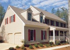
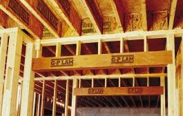
2 Build on the strength of Today s home designs call for advanced building materials like Georgia-Pacific engineered lumber. The strength of engineered lumber makes it the right choice for floor and roof systems, as well as beams and headers. Residential building trends, including large open spaces and high ceilings, create a demand for products that provide higher strength and greater stability over longer spans. Georgia-Pacific Wood I Beam joists and other engineered lumber products outperform conventional lumber in these applications, helping to ensure a solid floor system and maintain structural integrity. Engineered lumber helps eliminate the need for supporting posts in basements, garages and bonus rooms. Since most pipes, duct and wires can pass through the web of Wood I Beam joists, engineered lumber makes it possible for you to maximize ceiling heights, even in basements. When home designs feature walls of windows, grand front entrances, even wider doorways from room to room, engineered lumber products like G-P Lam LVL headers provide the strength and support required to handle the heavy loads. Engineered Lumber is an important part of every flooring system that is sturdy enough to support heavy furniture like pool tables, pianos or china cabinets. Take a closer look at the advantages offered by G-P engineered lumber: Strength Georgia-Pacific engineered lumber is manufactured to take advantage of the natural strengths found in wood. We combine high-grade wood fiber with specifically formulated resins to produce virtually defect-free engineered lumber. This manufacturing process enables G-P engineered lumber to resist shrinking, twisting and warping. As a result, engineered lumber is The Georgia-Pacific family of engineered lumber products includes: G-P Wood I Beam joists FiberStrong rim board G-P Lam LVL more consistent and has more loadcarrying capacity and spanning ability than regular sawn lumber. Easy installation Every piece is consistently true to size. Even though it s extremely strong, G-P engineered lumber is lightweight and easy to cut. Plus, wiring and plumbing pass easily through the web of Wood I Beam joists for more clearance and higher ceilings. Environmentally sound Engineered lumber makes more efficient use of trees because it is made using smaller, computer-evaluated lumber and plywood veneers. Engineered lumber requires between 40 to 50% less wood fiber than the equivalent conventional lumber. 2 Georgia-Pacific Corporation, January 2003


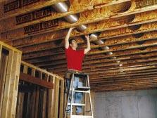
3 engineeredlumber. Wood I Beam Joists Floor Span Charts Bonus Room Floor Joist Selection Guide Consistently high quality G-P engineered lumber resists shrinking, crowning, twisting and warping, which means quieter floors and fewer callbacks. Plus, all Wood I Beam joists and G-P Lam LVL are backed by a limited lifetime warranty.* Cost effective The advantages of G-P engineered lumber go beyond superior performance. You ll find engineered lumber is the lowest total cost solution in the marketplace. The G-P Value Length method of ordering and shipping materials minimizes waste in labor and materials. Now, you can think like a framer instead of an engineer with a selection of standard sizes that can be trimmed on site to meet the needs of the job. "Jigsaw puzzle" job packs with dozens of lengths are eliminated, helping to greatly reduce the need for handling and cutting before joists get to the job. Dependable delivery and availability Georgia-Pacific manufactures engineered lumber to exacting standards at its mills, and G-P maintains an extensive inventory that s ready to be delivered through the largest distribution network in the industry. What does that mean to you? The quality engineered lumber you need is on your job site, when you need it. Customer & technical support Georgia-Pacific provides the knowhow to help you stay on top of current building practices. Plus, we can help you resolve day-to-day issues and provide technical assistance. Simply call us at BUILD GP. Simple-to-use software solutions Georgia-Pacific s exclusive Windows based software packages help you make the most of engineered lumber. FASTBeam analyzes a variety of load conditions to calculate structural joist and beam selections, choosing the optimum product based on cost, availability, size and spacing while dramatically reducing the time it takes to spec plans. FASTPlan, an easy-to-learn CAD program, is the quick, efficient way to draw accurate, detailed framing layouts and create materials lists. FASTOpt prepares precise cut lists to optimize materials, save time and reduce waste. Wood I Beam joists make it possible to maximize ceiling heights, create dramatic living spaces, and raise new opportunities for living areas in basements. Performance Based Joist Selection Guide FiberStrong Rim Board Roof Joist Span Charts Allowable Uniform Loads Floor PLF Allowable Uniform Loads Roof PLF Design Properties Architectural Specifications Framing Connectors Details Dead Load Material Weights Installation Notes and Safety Warnings Installation Do s and Don ts Typical Framing Fire Rated Assemblies Plumbing Details Floor Details Cantilever Details Roof Details Hole Location Charts G-P Lam LVL Bearing Details General Notes for Charts and Tables Floor Beams Window, Patio Door and Garage Door Headers Roof Hip and Valley Beam Bearing Length Requirements..40 Allowable Uniform Loads Fastening Recommendations Tapered Cut Allowable End Reactions Hole Chart and Connectors Framing Connectors Beam and Header Design Properties Architectural Specifications *See complete warranty for terms, conditions and limitations. Georgia-Pacific Corporation, January

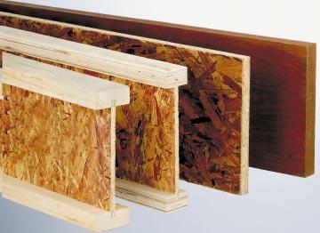
4 Wood I Beam Joists GPI Series 1 3 /4" 2 5 /16" 2 1 /2" WI Series 2 1 /2" 2 1 /2" 3 1 /2" NOTE: WI series joists have solid sawn lumber flanges. GPI series joists have LVL flanges. Not all products are available at all distribution centers; contact G-P for availability. *See complete warranty for terms, conditions and limitations. 9 /2" or 9 /2", 11, 11 /8" 11 /8",or 14" 14 ",or 16" GPI 20 GPI 40 GPI 65 All Wood I Beam joists have FiberStrong web 9 /2", 11, 11, 11 /8",or 14" 14 ",or 16 " 14 ",or 16" WI 40 WI 60 WI 80 4 Georgia-Pacific Corporation, January 2003


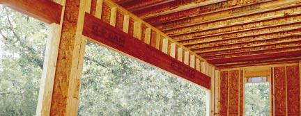
5 Greater load-carrying capacity, firmer-feeling floors Lightweight and cost effective, WI and GPI Series Wood I Beam joists are the builder s choice for residential floor and roof systems. A wide selection of sizes and flange choices make it easy to specify the materials that are right for the homes you build, whether you re building smaller tract homes or custom plans. Each joist features a FiberStrong OSB web with high-grade solid sawn lumber or G-P Lam LVL flanges. The wider flanges offered by the 40, 60, 65 and 80 series joists provide broader gluing and nailing surfaces for floor and roof sheathing, helping to save time and money for builders. Occupants enjoy the benefits of firm, level floors and smooth, flat ceilings. More stable floors When used as a part of a flooring system, Wood I Beam joists can help floors stay quiet over time, reducing bothersome and costly callbacks. Conventional lumber can shrink, twist and warp as the moisture found naturally in the wood evaporates. Floors can bow, nails pull away from the joists, and the floor decking slides up and down against the nails, creating annoying squeaks. In contrast, Wood I Beam joists are more stable by design. The wide flange helps reduce vibration, creating a firmer feeling floor. Wood I Beam joists Features & Benefits All series of Wood I Beam joists have a FiberStrong web. GPI 20 Series have 1-3 4" LVL flange width and are available in 9-1 2" and 11-7/8" depths. GPI 40 Series have 2-5/16" LVL flange width and are available in 9-1/2", 11-7/8" and 14" depths. GPI 65 Series have 2-1/2" LVL flange width and are available in 11-7/8", 14" and 16" depths. WI 40 Series have 2-1/2" Lumber flange width and are available in 9-1/2", 11-7/8" and 14" depths. WI 60 Series have 2-1/2" Lumber flange width and are available in 11-7/8", 14" and 16" depths. WI 80 Series have 3-1/2" Lumber flange width and are available in 11-7/8", 14" and 16" depths. All joists are available in value lengths of 24', 28', 32', 36', 40', 44' and 48'. Lengths up to 60' may be special ordered. All Wood I Beam joists are backed by a Limited Lifetime Warranty*. Floor Span Charts Bonus Room Floor Joist Selection Guide Performance Based Joist Selection Guide FiberStrong Rim Board Roof Joist Span Charts Allowable Uniform Loads Floor PLF Allowable Uniform Loads Roof PLF Design Properties Architectural Specifications Framing Connectors Wood I Beam joists help eliminate the need for support posts in basements, garages and bonus rooms. Georgia-Pacific Corporation, January
6 System Performance The ultimate goal in the design of a floor or roof system is the end user s safety and satisfaction. Although joists used at spans indicated in this guide meet or exceed minimum code criteria and will safely support the loads imposed on them, judgement must be used to adequately meet user expectation levels. These expectations may vary from one user to another. The specifier should consider the meaning of a given deflection limit in terms of allowable deflection and the effects this could have on the system. For example, L/360 (span/360) for a 30 span is 1 of deflection. L/240 would be 1-1/2, and L/180 would be 2 of deflection. Consideration might also be given to cases in which a joist with a long span parallels a short span or a foundation end wall. For example, a 30 span with up to 1 of allowable live load deflection could be adjacent to an end wall with no deflection, causing a noticeable difference in floor levels under full design load. A stiffer floor will result from using a live load deflection limit of L/480 versus the code minimum L/360. A roof system with less total load deflection than the code required L/180 may be achieved by using a criterion of L/240. In addition to more stringent deflection limits, several other factors may improve overall floor performance. Reducing joist spacing and/or increasing the subfloor thickness will lessen deflection between adjacent joists and increase load sharing. For increased floor stiffness, we recommend gluing the subfloor to the joists before nailing or screwing rather than nailing alone. For additional stiffness, glue tongue and groove joints. Surfaces must be clean and dry before gluing. As with any construction, it is essential to follow proper installation procedures. Joists must be plumb and anchored securely to supports before system sheathing is attached. Supports for multiple span joists must be level. To minimize settlement when using hangers, joists should be firmly seated in the hanger bottoms. Leave a 1 16 gap between joist end and header. Vibrations may occur in floor systems with very little dead load, as in large empty rooms. A ceiling attached to the bottom of the joists will generally dampen vibration as will interior partition walls running perpendicular to the joists. If a ceiling will not be attached to the bottom of the joists, vibration can be minimized by nailing a continuous 2 x 4 perpendicular to the bottom of the joists at midspan running from end wall to end wall. Where future finishing of the ceiling is likely, x-bridging or Wood I Beam blocking panels may be used in place of the 2 x 4. GPI and WI Series Joists Residential Floor Span Charts Span Illustrations Simple Spans Multiple Spans (see note 4) 40 PSF Load + 10 PSF Dead Load Improved Performance 1 (L/480) 40 PSF Load + 20 PSF Dead Load Improved Performance 1 (L/480) 6 Joist Joist Spacing (Simple Span) Spacing (Multiple Span) Depth 12 o.c. 16 o.c o.c. 24 o.c. 12 o.c. 16 o.c o.c. 24 o.c. GPI GPI GPI WI WI WI Joist Joist Spacing (Simple Span) Spacing (Multiple Span) Depth 12 o.c. 16 o.c o.c. 24 o.c. 12 o.c. 16 o.c o.c. 24 o.c. GPI GPI '-03 17' GPI WI WI WI NOTES: 1. These span charts are based on uniform loads, as noted above; live load deflection is limited to L/480 for better performance. Floor performance is greatly influenced by the stiffness of the floor joists. Experience has shown that joists designed to the code minimum live load deflection (L/360) will result in a floor which may not meet the expectations of some end users. G-P strongly recommends floor spans for Wood I Beam joists be limited to those given above, which are based on L/480 live load deflection. (One-third stiffer than required by code.) 2. Spans are clear distances between supports, and are based on composite action with gluednailed APA Rated Sheathing or Sturd-I-Floor of minimum thickness 19/32 (40/20 or 20 oc) for joist spacing of 19.2 or less, or 23/32 (48/24 or 24 oc) for a joist spacing of 24. Adhesive must meet APA AFG-01 or ASTM D3498. Apply a continuous line of glue (about 1/4 diameter) to top flange of joists. All surfaces must be clean and dry. If sheathing is nailed only (not recommended), reduce spans by Minimum end bearing length is 1-3/4. Minimum intermediate bearing length is 3-1/2. 4. End spans of multiple-span joists must be at least 40% of the adjacent span. 5. For loading other than that shown above, refer to Uniform Load Tables, use G-P FASTBeam selection software, or contact G-P Engineered Lumber Technical Services. 6. Not all products are available at all distribution centers; contact G-P for availability. Georgia-Pacific Corporation, January 2003
7 Bonus Room Floor Joist Selection Guide L X WI Joists (Series Depth) GPI 65 (Depth) (Span) (Kneewall Spacing Spacing Location) 12 o.c. 16 o.c o.c. 24 o.c. 12 o.c. 16 o.c o.c. 24 o.c Call G-P Call G-P Call G-P Call G-P Call G-P Call G-P Call G-P * Call G-P Call G-P Call G-P Call G-P 16 Call G-P Call G-P Call G-P Call G-P Call G-P 16 Call G-P Call G-P Call G-P Call G-P Call G-P 16 Call G-P Call G-P Call G-P Call G-P Call G-P Call G-P 16 Call G-P Call G-P Call G-P Call G-P Call G-P Call G-P 16 * Call G-P Call G-P Call G-P Call G-P Call G-P Call G-P 16 * Call G-P Call G-P Call G-P Call G-P Call G-P Call G-P 16 * Call G-P Call G-P Call G-P *Under these conditions, live load deflection meets building code, but does not meet L/480. Worst case is L/467. Design Parameters: 1. Glued and nailed floor sheathing. 2. Deflection limits: L/240 total load, L/480 live load, unless noted otherwise. 3. Roof loads of 30 PSF live load at 115% (snow load). 4. Roof dead load of 12 PSF (asphalt shingles). 5. Roof rafter slope between 8/12 and 12/ Kneewall weight of 40 PLF. 7. Attic storage load of 20 PSF live load (outside the kneewalls). 8. Floor live load of 40 PSF (between the kneewalls). 9. Attic and floor dead load of 10 PSF. 10. Straight gable roof framing. No hip framing is permitted. 11. For all other conditions, call Georgia-Pacific Engineered Lumber. X 2 x roof and wall framing Bonus Room Wood I Beam Floor Joist X L DO NOT DO or DO Rafter Rafter Extend floor sheathing to outside face of wall. Rafter Do not bevel cut joist beyond inside face of wall. Wood I Beam blocking or FiberStrong rim board required at bearing for lateral support Hanger Georgia-Pacific Corporation, January
8 Performance Based Joist Selection Guide Determine span, select desired performance level, choose joist option. Performance Criteria Load Deflection Deflection 1. Code allowed minimum* L/360 L/ Improved performance L/480 L/ (24 for WI 80) 3. High performance L/600 L/ (19.2 for WI 80) Max Joist Spacing Recommended Sheathing/ Sturd-I-Floor Product Selection Guide based on joist span. Determine span, select desired performance level, choose joist option. Products above the bold line in each column are limited to 1 /2 live load deflection when fully loaded /24 APA Rated Sheathing (glue is recommended) G-P Plus Plywood Sturd-I-Floor 24 o.c. or 48/24 APA Rated Sheathing, glued and nailed 7 8 G-P ToughPly plywood, glued and nailed Floor 1. CODE ALLOWED MINIMUM* 2. IMPROVED PERFORMANCE 3. HIGH PERFORMANCE Span Joist Depth Spacing Depth Spacing Depth Spacing GPI o.c o.c o.c. 40 Series o.c o.c o.c. 14 WI o.c o.c o.c. GPI o.c o.c o.c. WI o.c o.c o.c. GPI o.c o.c o.c. 40 Series o.c o.c o.c. 15 WI o.c o.c o.c. GPI o.c o.c o.c. WI o.c o.c o.c. GPI o.c o.c o.c. 40 Series o.c o.c o.c. 16 WI o.c o.c o.c. GPI o.c o.c o.c. WI o.c o.c o.c. GPI o.c o.c o.c. 40 Series o.c o.c o.c. 17 WI o.c o.c o.c. GPI o.c o.c o.c. WI o.c o.c o.c. GPI o.c o.c o.c. 40 Series o.c o.c o.c. 18 WI o.c o.c o.c. GPI o.c o.c o.c. WI o.c o.c o.c. GPI o.c o.c. Does not work 40 Series o.c o.c o.c. 19 WI o.c o.c o.c. GPI o.c o.c o.c. WI o.c o.c o.c. 40 Series o.c o.c. 20 WI o.c o.c. GPI o.c o.c. WI o.c o.c. 40 Series 14 * 16 o.c o.c. WI o.c o.c. 21 GPI o.c o.c. NOTE: WI o.c o.c. 40 Series Please refer to 14 * 12 o.c o.c. 22 WI o.c o.c. Improved Performance GPI o.c o.c. WI 80 or High Performance o.c o.c. 40 Series 14 * 12 o.c. Does not work 23 WI o.c o.c. GPI o.c o.c. WI o.c o.c. WI o.c. Does not work 24 GPI o.c o.c. WI o.c o.c. *Not Recommended. Experience suggests the end user may not be satisfied with the minimum system performance. NOTES: 1. Table assumes normal residential loads of 40 PSF live load and 10 PSF dead load except for High Performance column. High Performance system is based on 40 PSF live load, 20 PSF dead load. 2. Table assumes simple span applications. 3. If load bearing walls from above do not stack directly to walls or beams below, call G-P. 4. Many combinations of series, depth and on center spacing can provide desired performance levels; the recommendations in this table are based on performance, costs and installation factors. For other options contact Georgia-Pacific (8 ) Layout Guide for 19.2 o.c. Spacing (16 ) (24 ) 8 Georgia-Pacific Corporation, January 2003
9 FiberStrong Rim Board Sizes and Weights Depth 9 1 / / Weight (plf) Capacities Vertical Load: Rim or starter joist = 4850 plf. Horizontal load (lateral seismic or wind): 200 plf using a load duration factor of 160% 7 /8 lag or through bolt attaching ledger to rim board: 350 lbs. lateral load per bolt Lateral loads for nails in wide face of rim board: Design per 1997 NDS using Douglas Fir-Larch values Thickness 1 1 /8 Length 12 1 /2" sheathing Optional blocking for diaphragm nailing 2 x _ PT ledger attached per detail F6A below 8d nails at 69 o.c. (toe-nail) 8d nail top and bottom flange of I-joist FiberStrong used as starter joist FiberStrong rim board Constructed according to connection requirements below. Connection Requirements To joist: Face-nail rim board to each joist with two (2) 8d nails, one each into top and bottom flange. To plate: Toe-nail rim board to wall plate with 8d nails at 6 o.c. or 16d nails at 12 o.c. Subfloor: Attach floor sheathing to rim board per building code or structural panel manufacturer s specifications (closest oncenter nail spacing is 6 ). For shear transfer (lateral seismic or wind) of up to 200 PLF, use 8d at 6 o.c. Approved Applications FiberStrong rim board has been tested and approved as a rim board and starter joist by APA-EWS. FiberStrong rim board is not recommended as a structural joist, rafter, header or ledger. For such applications, consider Wood I Beam joists or G-P Lam LVL or contact Georgia-Pacific. F6A Sheathing To rim: Ledger: Face-nail rim boards together at corners with three (3) 8d nails. To attach a ledger use 1 2 through bolts with nuts and washers or 1 2 lag screws (minimum length of 4 ) with washers. Maintain 2 edge distances on ledger and rim board. For lag screws, drill 5 16 lead holes in rim board and 1 2 holes in ledger. Caulk holes with high quality caulking immediately before inserting the bolts or lag screws. Caution: The lag screw should be inserted in a lead hole by turning with a wrench, not by driving with a hammer. Overtorquing can significantly reduce the lateral resistance of the lag screw and should therefore be avoided. APA rim board 2x PT ledger 2-4 galvanized or stainless steel washers for spacers Extend flashing below 2x ledger and over siding Georgia-Pacific Corporation, January
10 Roof Joist Maximum Span Chart 125% (Non-Snow) 1. Roof joists to be sloped min. 1 4 in 12. No camber provided. 2. Maximum deflection is limited to L/180 at total load, L/240 at live load. 3. Maximum slope is limited to 12 in 12 for use of these tables. 4. Tables may be used for simple and multiple spans. 5. End spans of multiple-span joists must be at least 40% of the adjacent span. 6. For other loads or on-center spacing, see allowable uniform load table. 7. Minimum end bearing length is Minimum intermediate bearing length is Roof joist span measured horizontally Load Joist Slope of 4/12 or less Slope of over 4/12 through 8/12 Slope of over 8/12 through 12/12 (PSF) Joist Depth 16 o.c o.c. 24 o.c. 16 o.c o.c. 24 o.c. 16 o.c o.c. 24 o.c. GPI GPI Non-Snow % GPI Dead 10 WI WI WI Load Joist Slope of 4/12 or less Slope of over 4/12 through 8/12 Slope of over 8/12 through 12/12 (PSF) Joist Depth 16 o.c o.c. 24 o.c. 16 o.c o.c. 24 o.c. 16 o.c o.c. 24 o.c. GPI GPI Non-Snow % GPI Dead 15 WI WI WI Load Joist Slope of 4/12 or less Slope of over 4/12 through 8/12 Slope of over 8/12 through 12/12 (PSF) Joist Depth 16 o.c o.c. 24 o.c. 16 o.c o.c. 24 o.c. 16 o.c o.c. 24 o.c. GPI GPI Non-Snow % GPI Dead 20 WI WI WI Georgia-Pacific Corporation, January 2003
11 Roof Joist Maximum Span Chart 115% (Snow) Load Joist Slope of 4/12 or less Slope of over 4/12 through 8/12 Slope of over 8/12 through 12/12 (PSF) Joist Depth 16 o.c o.c. 24 o.c. 16 o.c o.c. 24 o.c. 16 o.c o.c. 24 o.c. GPI GPI Snow % GPI Dead 15 WI WI WI Load Joist Slope of 4/12 or less Slope of over 4/12 through 8/12 Slope of over 8/12 through 12/12 (PSF) Joist Depth 16 o.c o.c. 24 o.c. 16 o.c o.c. 24 o.c. 16 o.c o.c. 24 o.c. GPI GPI Snow % GPI Dead 15 WI WI WI Load Joist Slope of 4/12 or less Slope of over 4/12 through 8/12 Slope of over 8/12 through 12/12 (PSF) Joist Depth 16 o.c o.c. 24 o.c. 16 o.c o.c. 24 o.c. 16 o.c o.c. 24 o.c. GPI GPI Snow % GPI Dead 15 WI WI WI Load Joist Slope of 4/12 or less Slope of over 4/12 through 8/12 Slope of over 8/12 through 12/12 (PSF) Joist Depth 16 o.c o.c. 24 o.c. 16 o.c o.c. 24 o.c. 16 o.c o.c. 24 o.c. GPI GPI Snow % GPI Dead 15 WI WI WI Georgia-Pacific Corporation, January
12 General Notes, Allowable Uniform Loads Floor and Roof 1. Table values are based on clear distance between supports and may be used for simple or multiple spans. End spans of multiple span joists must be at least 40% of adjacent span. 2. For cases with cantilevers or point loads, use G-P FASTBeam Software or contact G-P. 3. Both live and total loads must be checked live load against the row and total load against the row. When no value is shown in the row, total load will govern. 4. Verify that the deflection criteria herein are accepted by local codes and authorities. 5. Provide lateral support at bearing points and continuous lateral support along the compression flange of each joist. 6. Minimum end bearing length is Minimum intermediate bearing length is For double joists, double the table values and connect joists per detail F For proper installation procedures, refer to appropriate sections in this publication. GPI and WI Series Joists Allowable Uniform Loads Floor Pounds per lineal foot (PLF) Joist GPI 20 GPI 40 WI 60 WI 40 GPI 65 WI 80 Depth 9 1 / /8 9 1 / / / / / / / NOTES: 1. Refer to General Notes above. 2. Table does not include additional stiffness from composite action with glue-nailed or nailed decking. 3. L/480 live load deflection is recommended (See System Performance narrative.) For L/360 (minimum code deflection) multiply L/480 value times load deflection is limited to L/240. Joist Span: L/ L/ L/ L/ L/ L/ L/ L/ L/ L/ L/ L/ L/ L/ L/ L/ L/ L/ L/ L/ L/ L/ L/ L/ L/ L/ L/ L/ L/ L/ L/ L/ L/ L/ L/ L/ L/ L/ L/ L/ L/ L/ L/ L/ L/ L/ L/ L/ L/ L/ L/ PSF to PLF Conversion Load in lbs. per lineal foot (PLF) o.c. spacing LOAD IN LBS. PER SQUARE FOOT (PSF) spacing factor Joist Spacing L1 L2 L1/2 L2/2 Calculating Uniformly Distributed Load (plf): L1(ft.) L2(ft.) ( + LL(psf) = LL(plf) 2 2 ) x L1(ft.) L2(ft.) ( + TL(psf) = TL(plf) 2 x 2 ) Check resulting loads against those in the appropriate chart. 12 Georgia-Pacific Corporation, January 2003
13 GPI and WI Series Joists Allowable Uniform Loads Roof Joist Depth Joist Span: 9 1 /2 GPI 20 GPI 40 WI 60 WI 40 GPI 65 WI /8 9 1 / / / / / / / NOTES: 1. Refer to General Notes on the previous page. 2. All roof joists to be sloped 1 4 in 12 minimum. Up-the-Slope Spans & Cutting Lengths for Sloped Roofs Joist Depth Slope Slope Factor Amount to Increase Length for Plumb Cut (Lp in feet) in in in in in in in in in in in in in Pounds per lineal foot (PLF) L / % % L / % % L / % % L / % % L / % % L / % % L / % % L / % % L / % % L / % % L / % % L / % % L / % % L / % % L / % % L / % % L / % % Use of this table for horizontal spans should be limited to roof slopes of 2 per foot or less. For greater slopes, convert horizontal span to up-the-slope span using the chart below. 4. load deflection is limited to L/180. For less deflection use the L/240 row. Georgia-Pacific Corporation, January L Lh x SLOPE FACTOR Joist Depth Lh L=Lh x SLOPE FACTOR + Lp (in Ft.) EXAMPLE: 7/12 slope and 20-0 horizontal span, 2-0 overhang (horizontal) one end 22 x 1.16 = up-the-slope If a 14 joist will be used, add 0.68 feet = x 12 = 2.4 or approximately 2¹ ₂. L = 26-2¹ ₂ Lp
14 Design Properties For Wood I Beam Joists Allowable Moment Allowable Allowable Reactions Joist Joist Weight a EI Single b,f Repetitive c,f Shear f End d,f Intermediate e,f C Depth (lbs/ft) (10 6 inch 2 lbs) (ft-lbs) (ft-lbs) (lbs) (lbs) (lbs) (10 6 ft-lbs/in) GPI GPI GPI WI WI WI NOTES: a. Weight of joists for dead load calculations. For shipping weights contact Georgia-Pacific. b. For a single joist. c. For use when a minimum of 3 joists are spaced 24 o.c. or less. d. Allowable end reaction is based on a minimum bearing length of without bearing stiffeners. For a bearing length of 4, the allowable end reaction may be set equal to the tabulated shear value. Interpolation of the end reaction between and 4 bearing is permitted. For end reactions values over 1,550 lbs., bearing stiffeners are required. e. Allowable intermediate reaction is based on a minimum bearing length of f. Allowable moment, shear, and reaction values are for normal duration loading and may be increased for other load durations in accordance with code. g. APPROXIMATE DEFLECTION* (Inches) = 22.5 x W x L 4 W x L 2 W = Uniform Load (lbs/foot) + EI C L = Span (feet) EI = Stiffness Constant *Constants have been adjusted to maintain unit consistency. C = Shear Deflection Constant Wood I Beam Joist Cross Sections GPI Series WI Series 1 3 /4" 2 5 /16" 2 1 /2" 2 1 /2" 2 1 /2" 3 1 /2" 9 1 /2" or 9 1 /2", 11 7 /8 " 11 7 /8",or 14" 11 7, 14 " /8",or 16" 9 1 /2", 11 7 /8",or 14" 11 7, 14 " /8",or 16 " 11 7, 14 " /8",or 16" GPI 20 GPI 40 GPI 65 WI 40 WI 60 WI 80 All Wood I Beam joists have FiberStrong web 14 Georgia-Pacific Corporation, January 2003
15 Wood I Beam Architectural Specifications Part 1 General 1.0 Description: A. Work in this section includes, but is not limited to: Prefabricated Wood I Beam GPI 20, GPI 40, GPI 65, WI 40, WI 60 and WI 80 ceiling, floor, and roof joists with FiberStrong webs and lumber flanges (WI) or LVL flanges (GPI). B. Related work specified elsewhere: Rough carpentry. 1.1 Submittals: A. Product data: Submit manufacturer s descriptive literature indicating material composition, thicknesses, dimensions, loading and fabrication details. B. Shop drawings or installation guide: Manufacturer s literature indicating installation details. Include locations and details of bearing, blocking, bridging, and cutting and drilling of webs for work by others. 1.2 Quality Assurance: A. Certification: All Georgia-Pacific Wood I Beam joists have been qualified to ASTM D5055 by APA-The Engineered Wood Association. 1.3 Delivery, Storage and Handling: A. Delivery: Deliver materials to the job site in manufacturer s original packaging, containers and bundles with manufacturer s brand name and identification intact and legible. B. Storage and handling: Store and handle materials to protect against contact with damp and wet surfaces, exposure to weather, breakage and damage. Provide air circulation under covering and around stacks of materials. Individual joists shall be handled in the upright position. 1.4 Limitations: A. Loads: Concentrated loads shall not be applied to the bottom flange. B. Cutting: Except for cutting to length, top and bottom flanges of Wood I Beam floor and roof joists shall not be cut, drilled or notched. C. Wood I Beam joists are for use in covered, dry conditions only. Part 2.0 Products 2.1 Prefabricated Wood Beams and Joists: A. Acceptable products: 1. Georgia-Pacific Corporation, WI Georgia-Pacific Corporation, WI Georgia-Pacific Corporation, WI Georgia-Pacific Corporation, GPI Georgia-Pacific Corporation, GPI Georgia-Pacific Corporation, GPI 65. B. Characteristics: 1. Flanges: High-grade lumber flanges. a. WI 40: 2¹ ₂. b. WI 60: 2¹ ₂. c. WI 80: 3¹ ₂. LVL flanges. a. GPI 20: 1³ ₄. b. GPI 40: c. GPI 65: Webs: ³ ₈ thick APA Rated FiberStrong OSB. 3. Beam depths: a. GPI 20: 9¹ ₂ and 11⁷ ₈ as required for loading, deflection and span. b. GPI 40 or WI 40: 9¹ ₂, 11⁷ ₈ and 14 as required for loading, deflection and span. c. WI 60: 11⁷ ₈, 14 and 16 as required for loading, deflection and span. d. GPI 65: 11⁷ ₈, 14 and 16 as required for loading, deflection and span. e. WI 80: 11⁷ ₈, 14 and 16 as required for loading, deflection and span. 4. Beam length: As required for span and bearing. 2.2 Accessories: A. Nails: 8d, 10d, and 12d box, sinker, and common nails. B. Bracing and blocking: 1. Bearing stiffeners: 2 x 4 or combination of ³ ₈, ¹ ₂ or ⁵ ₈ plywood or OSB. 2. Band joists and continuous closure at load-bearing walls: per standard approved Wood I Beam details. 3. Lateral support at intermediate supports of multiple span joists: Wood I Beam blocking. C. Joist hangers: 1. Model numbers are shown for United Steel Products and Simpson Strong-Tie connectors. Contact Georgia-Pacific for other acceptable connectors. Part 3 Execution 3.0 General: A. Provide Wood I Beam floor and roof joists where indicated on drawings using hangers and accessories specified. B. Install Wood I Beam joists in accordance with manufacturer s recommendations. C. Install and brace Wood I Beam floor and roof joists to prevent dominoing of system and buckling of top flange. 3.2 Accessories: Install accessories where indicated and in accordance with manufacturer s instructions. Georgia-Pacific Corporation, January
16 Framing Connectors for Wood I Beam Joists USP Lumber Connectors * TMP TMPH Joist GPI 20 Joist Width GPI 40 Joist Width WI 40, 60 & GPI 65 Joist Width Joist Depth Top Cpcy 1, 2 Nailing 7 Cpcy 1, 3 Nailing Double Cpcy 1,3,4 Field Cpcy 1, 3, 5 Cpcy Nailing 7 Nailing 7 1, 6 Lbs- Face Lbs- Face Lbs- Sloped Lbs- Variable Lbs- Nailing 7 Mount 100% H J Mount 100% H J Mount 100% H J & Skewed 115% H J Pitch 115% P J TH d x d x THF d 10d x THF d 10d x TMU d 10d x TMP d 10d x TH d x d x THF d 10d x THF d 10d x TMU d 10d x TMP d 10d x THO d x d x THF d 10d x THF d 10d x TMU d 10d x TMP d 10d x THO d x d x THF d 10d x THF d 10d x TMU d 10d x TMP d 10d x THO d x d x THF d 10d x THF d 10d x TMU d 10d x TMP d 10d x THO d x d x THF d 10d x THF d 10d TMU d 10d x TMP d 10d x THO d x d x THF d 10d x THF d 10d TMU d 10d x TMP d 10d x THO d x d x THF d 10d x THF d 10d TMU d 10d x TMP d 10d x THO d x d x THF d 10d x THF d 10d TMU d 10d x TMP d 10d x THO d x d x THF d 10d x 1 WI 1 2 HD d 10d TMU d 10d x TMP d 10d x THO d x d x THF d 10d x HD d 10d TMU d 10d x TMP d 10d x Joist Width THO d x d x THF d 10d x HD d 10d TMU d 10d x TMP d 10d x *Georgia-Pacific stocks a full line of USP lumber connectors. Simpson Strong-Tie Connectors NOTES: 1. Capacity is for the stated duration of load 100% floor loading 115% roof snow loading. Connector capacity depends on the model selected, quantity and size of nails used, and the size and type of fastener support. Douglas Fir-Larch or Southern Pine web filler material has been assumed for all I-joist series and depths except for all WI 80 depths where S-P-F has been used. Higher capacities may be available based on different header materials; please refer to appropriate reference/design guide from the connector manufacturer for expanded design information. Some connector/header/fastener combinations may not meet maximum joist reaction capacities and a qualified engineer should be consulted. VPA and TMP connectors are based on S-P-F wood plates. Clinch nails across grain when possible. 2. Top mount hanger capacities shown are based on the same series and depth of Wood I Beam joists carried. To achieve design capacity shown, use 10d nails for single thick G-P Lam LVL beams and 16d nails for double thick (3 1 2 ) G-P LVL, Douglas Fir-Larch or Southern Pine glulam beams. Refer to detail F Hangers capacities are based on the lesser value of single thick G-P Lam LVL, Douglas Fir-Larch or Southern Pine Glulam beams or the same series and depth of Wood I Beam joists carried. Refer to detail F13 and R1. 4. Bearing stiffeners required for Wood I Beam applications. Refer to detail F Beveled bearing stiffeners are required. Refer to detail R8. Maximum slope is 12/12. A tie strap is required for all Wood I Beam applications with 16 joist depths or slopes of 7/12 and greater. Refer to detail R1. 6. TMP connectors may be used for slopes of 1/12 through 6/12. For greater slopes use TMPH series connectors with bearing stiffeners. 7. Nailing key. H column indicates size of nails to connect hanger to supporting header. J column indicates nails to attach the hanger to the joist. P indicates nails to connect to plate. Fill all nail holes as required by hanger manufacturer. 10d x is 9 gauge x 1 1 2, 10d is 9 gauge x 3, 16d is 8 gauge x NOTE: Model numbers shown are for United Steel Products Company, Inc (East) & (West) and Simpson Strong-Tie Company, Inc Some locations carry similar products produced by other manufacturers. Contact your local building material retailer or Georgia-Pacific for conversion information and details. Other designs are available for specialized applications. 16 Joist GPI 20 Joist Width GPI 40 Joist Width WI 40, 60 & GPI 65 Joist Width WI 80 Joist Width Cpcy 1, 2 Cpcy 1, 3 Nailing Double Cpcy 1,3,4 Field Cpcy 1, 3, 5 Cpcy Joist Nailing 7 7 Nailing 7 Nailing 7 1 Nailing Top Lbs- 7 Face Lbs- Face Lbs- Sloped Lbs- Variable Lbs- Depth Mount 100% H J Mount 100% H J Mount 100% H J & Skewed 115% H J Pitch 115% P J ITT d x d x IUT d 10d x MIU d 10d x LSSUI d 10d x VPA d 10d x ITT d x d x IUT d 10d x MIU d 10d x LSSUI d 10d x VPA d 10d x ITT d x d x IUT d 10d x MIU4.75/ d 10d x LSSUI d 10d x VPA d 10d x ITT d x d x IUT d 10d x MIU4.75/ d 10d x LSSUI d 10d x VPA d 10d x ITT d x d x IUT d 10d x MIU4.75/ d 10d x LSSUI d 10d x VPA d 10d x ITT d x d x IUT d 10d x MIU d 10d x LSSUH d 10d x VPA d 10d x ITT d x d x IUT d 10d x MIU d 10d x LSSUH d 10d x VPA d 10d x ITT d x d x IUT d 10d x MIU d 10d x LSSUH d 10d x VPA d 10d x MIT d x d x IUT d 10d x MIU d 10d x LSSUH d 10d x VPA d 10d x ITT d x d x IUT d 10d x HU d 16d LSSU d 10d x VPA d 10d x ITT d x d x IUT d 10d x HU d 16d LSSU d 10d x VPA d 10d x MIT d x d x IUT d 10d x HU d 16d LSSU d 10d x VPA d 10d x Georgia-Pacific Corporation, January 2003
17 Wood I Beam Details Dead Load Material Weights Pounds per square foot (PSF) Material PSF Sheathing and Decking (based on 36 pcf) plywood plywood plywood plywood plywood OSB OSB OSB OSB OSB Tough-Ply x decking x decking x decking gage metal deck gage metal deck Ceilings 1 2 gypsum board gypsum board Metal suspension system with acoustical tile Wood suspension system with acoustical tile plaster with lath Roofing 2-15 lb. and 1-90 lb. rolled lb. and 1-90 lb. rolled ply and gravel ply and gravel ply and gravel Single ply membrane and gravel Asphalt shingles Tough-Glass Tough-Glass Plus Summit Summit III Wood shingles Asbestos-cement shingles Clay tile (minimum) Concrete tile (Monier ) Spanish tile Material PSF Miscellaneous Mechanical ducts Skylight, metal frame 3 8 glass Stucco Floor Fill lightweight concrete regular concrete GYP-CRETE Floor Finish Hardwood (nominal 1 ) Carpet and pad Linoleum or soft tile ceramic or quarry tile (without mortar) mortar bed mortar bed x Framing (12 on center) 2x4 (for 16 o.c. divide by 1.33) x6 (for 16 o.c. divide by 1.33) x8 (for 16 o.c. divide by 1.33) x10 (for 16 o.c. divide by 1.33) x12 (for 16 o.c. divide by 1.33) GPI (for 19.2 o.c. divide by 1.6) WI (for 19.2 o.c. divide by 1.6) See page 14 for weight per lineal foot Interior Walls (wood or steel studs) 5 8 gypsum each side gypsum one side plaster one side Plaster both sides Exterior Walls (2x6 studs with insulation) 5 8 gypsum and siding gypsum and stucco Windows, glass, frame and sash gypsum and brick veneer Note: Wall weights are per square foot of wall Multiply weight times wall height for plf. Insulation (per 1 thickness) Rigid Batts G-P Technical Services recommends PSF for miscellaneous dead loads. Installation Notes and Safety Warnings Installation Do s and Don ts Typical Framing Fire Rated Assemblies Plumbing Details Floor Details Cantilever Details Roof Details Hole Location Charts Georgia-Pacific Corporation, January
18 Storage and Handling A. Bundles should be stored level. B. Wood I Beam joists shall not be stored in direct contact with the ground and should be protected from weather. C. Do not open bundles until time of installation. Use care when handling bundles and individual components to prevent injury to handlers or damage by forklifts or cranes. D. Stack and handle beams in the upright position. E. Twisting of joists, or applying loads to the joist when flat can damage the joist. F. Damaged Wood I Beam joists should not be used. Safety Warning Wood I Beam joists will not support workers or other loads until properly installed and braced. To minimize risk of injury, each Wood I Beam joist shall be properly fastened as it is erected. Continuous closure and/or blocking panels must be installed and attached prior to installing floor or roof sheathing. Lateral restraint, such as an existing deck or braced end wall, must be established at the ends of the bay. Alternatively, a temporary or permanent deck (sheathing) may be nailed to the first 4 feet of joists at the end of the bay. Rows of temporary bracing at right angles to joists must be fastened with a minimum of two 8d nails (10d box nails if net thickness of bracing exceeds 1") to the upper surface of each parallel joist and the established lateral restraint. Bracing should be 1x4 minimum and at least 8' long with on-center spacing not to exceed 10'. Ends of adjoining bracing should lap over at least two joists. Stack building materials over main beams or walls only. Improper storage or installation, failure to follow applicable building codes, failure to follow proper load tables, failure to use acceptable hole sizes and locations, or failure to use bearing stiffeners when required can result in serious accidents. Installation notes must be followed carefully. Do not allow workers or loads on Wood I Beam joists until properly installed and braced as outlined above. Stack building materials over main beams or walls only. Installation Notes A. Except for cutting to length, top and bottom flanges of Wood I Beam joists shall not be cut, drilled or notched. B. Concentrated loads shall only be applied to the upper surface of the top flange, not suspended from the bottom flange. Contact G-P for exceptions. C. Any fastening, resistance to uplift or member not specifically detailed is subject to local approval. D. When nailing sheathing to top flange, follow sheathing manufacturer s nailing recommendations, but maintain spacing in the ranges shown below: Sheathing Nail Spacing Requirements GPI 20 GPI 40, WI 40, WI 60, Nail Size GPI 65 WI 80 Min. Max. Min. Max. Min. Max. 8d Box, 8d Common d Box, 12d Box d Common, 12d Common NOTES: 1. If more than one row of nails is required, rows must be offset by at least 1 2 ( 3 4 for WI joists) and staggered gauge staples may be substituted for 8d nails if staples penetrate the joist at least Do not use nails larger than those shown above when attaching sheathing to flanges of Wood I Beam joists. Example: When using 8d common nails and GPI 20 series joists, space no closer (min.) than 3 o.c. and no farther (max.) than 16 o.c. E. End bearing length must be at least 1-3/4". Intermediate bearings of multiple span joists shall be at least 3-1/2". F. Engineered lumber must not remain in direct contact with concrete or masonry construction and shall be used in dry use conditions only. G. Wood I Beam joists must be restrained against rotation at the ends of joists by use of rim joists, blocking panels, or cross bridging. To laterally support cantilevered joists, blocking panels must also be installed over supports nearest the cantilever. H. Additionally, rim joists, blocking panels or squash blocks must be provided under all exterior walls and interior bearing walls to transfer loads from above to the wall or foundation below. I. Plywood or OSB subfloor nailed to the top flange of a Wood I Beam joist is adequate to provide lateral support. J. The top flanges must be kept straight within 1/2" of true alignment. K. In all details where plywood is referenced for backer block, filler block or stiffener material, rated OSB sheathing of the same thickness may be substituted. 18 Georgia-Pacific Corporation, January 2003
19 Installation Do s and Don ts DO NOT Do not cut or notch flanges (except birdsmouth cuts in roof details R4 & R6.) DO DO NOT DO Do not violate hole chart rules. (See Hole Charts on pages 30 & 31) DO NOT Do not birdsmouth cut bottom flange at high end of rafter. DO Wood I Beam Support beam Wood I Beam Continuous wedge or approved fastener Support beam (Refer to detail R2.) DO NOT DO or DO Do not hang Wood I Beam joist by top flange or web. Rim Board Hanger DO NOT DO or DO Rafter Rafter Extend floor sheathing to outside face of wall. Rafter Do not bevel cut joist beyond inside face of wall. Wood I Beam blocking or FiberStrong rim board required at bearing for lateral support Hanger Georgia-Pacific Corporation, January
20 Typical Framing R1 R7 R11 R3 R4 or R5 R8 P1 R6 R10a R10b Optional overhangs F15a optional x-bridging F15b Masonry hanger Face mount hanger Flush ledger Temporary bracing Incomplete as shown. Refer to SAFETY WARNING on page 18 for complete bracing information, typ. F9 F2 F10 Dropped ledger F12 or F13 F11 F14 F19 C3 F7 F5 F6 FiberStrong rim board Non-stacking loads require additional consideration. C5 20 Georgia-Pacific Corporation, January 2003
21 Fire Rated Assemblies for Wood I Beam Joists For alternate assemblies, including a two-hour rated system, contact Georgia-Pacific. One-Hour Fire-Resistive Floor-Ceiling Assembly (Applicable to all Wood I Beam joists) Floor APA Rated Sturd-I-Floor T&G wood structural panel, face grain perpendicular to joists, glued-nailed to joists with 1 4 bead of exterior construction adhesive and 8d common nails spaced per code requirements. Maximum joist spacing 24 o.c. Ceiling Two layers 5 8 Type X gypsum wallboard applied with long dimension perpendicular to joists base layer attached to bottom flange of joists with Type S drywall screws, 24 o.c., face layer attached to joists through base layer with 1 7 8" Type S drywall screws 12 o.c. at joints and intermediate joists and Type G drywall screws 12 o.c. placed 2 back on either side of end joints. Joints offset 24 from base layer end and edge joints. Plumbing Details One-Hour Fire-Resistive Floor-Ceiling Assembly (Applicable to WI series joists only) Floor APA Rated Sturd-I-Floor T&G wood structural panel, face grain perpendicular to joists, glued-nailed to joists with 1 4 bead of construction adhesive and 8d common nails spaced per code requirements. T&G joints glued with 1 4 bead of construction adhesive. Maximum joist spacing 24 o.c.; minimum bearing on supports 2. Furring 25 gauge steel resilient or hat channels, perpendicular to I-joists in continuous rows spaced up to 16 o.c. (up to 24 o.c. if joist spacing does not exceed 16 o.c.), attached to bottom flange of each I-joist with one Type S (resilient channel) or two 1 Type S drywall screws (hat channel). Center channel splices under I-joists and overlap a minimum of Install additional channels midway between adjacent continuous channels, at locations of end joints in base layer. Ends of these channels must extend a minimum of 6 beyond the edge joints of adjoining gypsum wallboard panels. Ceiling Two layers 5 8 Type X gypsum applied with long dimension perpendicular to channels base layer attached to channels with Type S drywall screws 24 o.c. face layer attached to channels through base layer with Type S drywall screws 12 o.c. joints offset at least 24 from base layer end and edge joints, end joints centered on channels. At end joints, also attach face layer to base layer with type G screws 12 o.c. spaced 2 from joint. P1 JOIST SPACING BELOW PLUMBING WALL Parallel to wall P2 JOIST SPACING BELOW PLUMBING Joist Spacing Joist 2 x 4 Wall 2 x 6 Wall GPI , 60 and 65 Series 6 8 WI Non-load bearing only Tub above Chart dimension Every third joist may be shifted up to 3 to avoid plumbing interference. Every third joist may be shifted up to 3 to avoid plumbing interference. Georgia-Pacific Corporation, January
22 Floor Details F1 ATTACHMENT AT END BEARING F2 BLOCKING PANEL, EXTERIOR Vertical load transfer = 2000 plf max. One 10d box or sinker nail each side at bearing, typical for all wood bearings. Wood I Beam blocking panel 1-3/4 minimum end bearing length at all floor and roof details To avoid splitting flange, start nails at least 1-1/2 from end. Drive nails at an angle to prevent splitting of bearing plate. 8d nails at 6 o.c. (or per design professional s specs., but complying with Installation Note D, page 18.) F3 WOOD I BEAM RIM JOIST Vertical load transfer = 2000 plf max. F4 SQUASH BLOCKS & SINGLE RIM Vertical load transfer = 2000 plf max. along load bearing wall based on bearing stress of 390 psi. Wood I Beam rim joist 23/32 48/24 APA rated sheathing Squash Blocks (2x4 minimum) Minimum 1-3/4 joist bearing at wall For siding use backer block per F13. 8d nails at 6 o.c. (or per design professional s specs., but complying with Installation Note D, page 18.) 1/16 8d nails Toe-nail rim joist to top flange of joist with 10d nail See detail F7 for blocking requirements. Check local building code for appropriate detail in areas of high lateral load. F5 Optional blocking for diaphragm nailing FIBERSTRONG RIM BOARD CLOSURE Vertical load transfer = 4850 plf F6 DECK ATTACHMENT Sheathing G-P FiberStrong rim board 2x PT ledger Fill holes with high-quality caulking 2-4 galvanized or stainless steel 2 washers for spacers G-P FiberStrong rim board 2 (min) Extend flashing below 2x ledger and over siding G-P FiberStrong rim board (3) 8d nails at corners 8d nail top and bottom flange 8d nails at 6 on center toe-nail to plate, typical Siding 1/2 sheathing 8d nails at 6 on center toe-nail to plate, typical 8d nail top and bottom flange Metal flashing 1/2 sheathing 2 x PT ledger attached with 1/2 diameter x 4 through bolts with washers and nuts (or 1/2 x 4 lag screws). 350# per bolt. Lower fastener may alternately be located in rimboard. Maintain 2" edge distance. Caution: The lag screw should be inserted in a lead hole by turning with a wrench, not by driving with a hammer. Over-torquing can significantly reduce the lateral resistance of the lag screw and should therefore be avoided. 22 Georgia-Pacific Corporation, January 2003
23 Floor Details F7 BLOCKING PANELS USED FOR BRACING Single layer 23/32 : rated sheathing (plywood or OSB) rim provides 1000 plf vertical load transfer (two layers=2000 plf). 23/32 plywood or OSB rim allowed only with joist depths up to 11-7/8 unless used with 2 x 4 min. squash blocks as shown in detail F4. F8 BEVEL CUT JOIST Do not bevel cut joist beyond inside face of support. Blocking panels installed for a minimum of 4 at each building corner and at least 4 every 25 of wall length. Use 8d nails at 6 o.c. Note: Wood I Beam blocking or x-bridging required at bearing for lateral support. F9 Check local building code for appropriate detail in areas of high lateral load. BLOCKING PANEL, INTERIOR Vertical load transfer = 2000 plf max. along load bearing wall. Load bearing wall must stack over blocking and wall or beam below.* When two joists meet over wall, provide 1-3/4 minimum bearing for each joist and install blocking panel to support both joists. Blocking panels not required when joists are continuous over wall and no load bearing wall exists above. F10 Check local building code for appropriate detail in areas of high lateral load. SQUASH BLOCKS AT INTERIOR BEARING Vertical load transfer = 2000 plf max along load bearing wall. Load bearing wall must stack over squash blocks and wall or beam below.* 1/16 Attach joist with one 10d box or sinker nail on each side of bearing. 8d nails at 6 o.c. (or per design professional s specs., but complying with Installation Note D, see page 18.) *Non-stacking walls require additional consideration. Squash block (2x4 minimum) Not required if no load bearing wall exists above. Bearing wall, G-P Lam LVL or glulam beam 8d nails *Non-stacking walls require additional consideration. Check local building code for appropriate detail in areas of high lateral load. F11 DOUBLE JOIST CONSTRUCTION Joist Joist Regular Filler Blocking* Full-depth Filler Blocking Depth Use in details F12, C4 & R7 Use in details F13 & F14 GPI GPI GPI 65 WI 40 WI WI x6 2 x x6 2 x x OSB/plywood 2 x OSB/plywood x OSB/plywood 2 x OSB/plywood 14" 2 x OSB/plywood 2 x OSB/plywood x OSB/plywood 2 x OSB/plywood x OSB/plywood 2 x OSB/plywood 14" 2 x OSB/plywood 2 x OSB/plywood 16" 2 x OSB/plywood 2 x OSB/plywood (2) 2 x 8 (2) 2 x 8 14" (2) 2 x 8 (2) 2 x 10 16" (2) 2 x 8 (2) 2 x 12 1/8 gap Filler blocking 1. Support back of web during nailing to prevent damage to web-flange connection. 2. Leave ¹ ₈ gap between top of filler blocking and bottom of top flange. 3. Block solid between joists for full length of span. 4. Place joists together and nail from each side with 2 rows of 10d nails at 12 o.c., clinched when possible. Stagger rows from opposite sides by Georgia-Pacific Corporation, January
24 Floor Details F12 FLOOR OPENING, TOP MOUNT HANGERS Backer Blocks* Joist Joist Depth Material Depth GPI , x GPI , GPI 65, WI 40, WI , 14, WI , 14, 16 2x *Block must be long enough to permit required nailing without splitting. A Backer Block (use if hanger load exceeds 250 lbs.) Before installing a backer to a double joist, drive an additional (3) 10d nails into the web where the backer will fit. Clinch when possible. Install backer tight to top flange. Use (10) 10d nails, clinched when possible. Assemble double joist per detail F11. (regular filler) B F13 FLOOR OPENING, FACE MOUNT HANGERS Backer block Before installing a backer to a double joist, drive an additional (3) 10d nails into the web where the backer will fit. Clinch when possible. Install backer tight to top flange. Use (10) 10d nails, clinched when possible. Assemble double joist per detail F11. (full-depth filler) Bearing stiffeners may be required at hangers. (See detail F18) Backer Blocks* Joist Joist Depth Material Depth GPI , GPI , , , 8 3 4, GPI 65, WI 40, WI 60 WI , , 14, , 14, net 6 1 4, 8 3 4, , , , *Block must be long enough to permit required nailing without splitting. Backer depth to equal joist depth minus A Backer blocks both sides of web. B F14 STRINGER TO JOIST CONNECTION Double Wood I Beam construction per detail F11 (full depth filler). Backer blocking size and installation per detail F13. Hangers for 14 (max) Stringer Nailing Requirement United Steel Products MSH 218 Minimum (12) 10d nails into double joists or OR single or double LVL header. Minimum Simpson Strong-Tie THA 218 (4) 10d x nails into stringer. For stringers longer than 14 or stringer reaction greater than 700 lbs., call G-P. 24 Georgia-Pacific Corporation, January 2003
25 Floor Details F15 JOIST TO BEAM CONNECTION F16 JOIST TO BEAM CONNECTION, STEP DOWN A Bearing stiffeners may be required at hangers. (See detail F18) G-P Lam LVL or Glulam Beam Bearing plate. Plate must be flush with inside face of beam. Face mount hanger Note: Bearing stiffeners may be required (see detail F18). Top mount hangers* *Appropriate face mount hangers may be substituted. Top mount hangers* Steel Beam B Note: Solid wood blocking of the steel beam required for face mount hangers on steel beam. Ledger for floor sheathing attachment G-P Lam LVL or Glulam Beam F17 JOIST TO BEAM CONNECTION, STEP DOWN F18 BEARING STIFFENERS Gap (1/4 ±) 23/32 48/24 APA rated sheathing or G-P approved rim. 8d nails Bearing stiffeners may be required at hangers. (See detail F18) G-P Lam LVL or Glulam Beam Joist Minimum Nails Stiffener Size GPI (3) 10d GPI (3) 10d GPI (3) 10d WI (3) 10d WI (3) 10d WI (min.) (3) 12d 2 ± Clinch nails when possible Plywood or OSB stiffeners each side at: - Hangers with side nailing - Hangers with sides not containing top flange of joists. - Birdsmouth cuts APA rated sheathing or Sturd-I-Floor 2 ± See detail F7 for blocking requirements. Hanger Tight fit F19 SQUASH BLOCKS AT CONCENTRATED LOADS 1/16 gap F20 WEB STIFFENERS Concentrated load from above 1/4 gap Use when concentrated loads exceed the values in the chart below. Install stiffeners per detail F18 but tight against top flange and gap at bottom. Verify adequacy of joist to carry concentrated load. Solid block all posts to bearing below with equal number of squash blocks Joist Depth Web stiffeners required if all series concentrated load exceeds lbs lbs lbs lbs. Georgia-Pacific Corporation, January
26 Cantilever Reinforcement Requirements for GPI or WI Joists ROOF LOADINGS Roof TL = 35 psf TL = 45 psf TL = 55 psf Joist Truss LL not to exceed 20 psf LL not to exceed 30 psf LL not to exceed 40 psf Depth Span Joist spacing Joist spacing Joist spacing X 1 2 X X X 1 2 X X X 2 X X X X X 2 X X X X 1 2 X X 2 X X X X 1 2 X X 2 X X X X X X X X X 1 2 X X X 1 2 X X X X 1 2 X X X X 1 2 X X X X X X X X X X 0 1 X X X 0 1 X X X X 0 1 X X X X 0 2 X X X X X X X X X X 0 1 X X X 0 1 X X X X 0 2 X X X X 0 2 X X X 0 1 X X 0 2 X X 0 - No reinforcement is required. See Detail C Single Reinforcement is required. See Detail C Double Reinforcement is required. See Detail C3 or C4. X - Joist does not work. Select closer spacing or deeper joist. NOTES: 1. Assumes floor load of 40 psf live load at L/480, 10 psf dead load and maximum joist simple spans. 2. Assumes exterior wall load of 80 plf. Wall load based on 3-0 maximum width window or door openings. For larger openings, or multiple 3-0 width openings spaced less than 6-0 o.c., additional joists beneath the opening s cripple studs may be required. 3. Roof loads use a load duration factor of 115%. See detail F9 ROOF SPAN See details C1, C2, C3, C4 Wood I Beam joist reinforcement may be required at cantilever. See table above. 2-0 Max. 26 Georgia-Pacific Corporation, January 2003
27 Cantilever Details C1 CANTILEVER, UNREINFORCED For allowable wall/roof loads on cantilever, use chart to left, use FASTBeam software or contact Georgia-Pacific. X-bridging or Wood I Beam blocking panels (see detail F2) required at cantilevers and continuing for 4 on each side of cantilevered area. C2 CANTILEVER, REINFORCED Single Sheathing (Option I) X-bridging or Wood I Beam blocking panels (see detail F2) required at cantilevers and continuing for 4 on each side of cantilevered area. 23/32 APA rated sheathing or FiberStrong rim board. Note: Wood I Beam joists shall be protected from the weather. Uniform loads only *Cantilever length may not exceed 1/4 the adjacent span (L). In addition: A) If end of cantilever supports wall/roof loads, max. cantilever length is 2-0. B) If no loads are placed on end of cantilever, max. cantilever length is 4-0. For other conditions contact Georgia-Pacific. L/4 max.* L 23/32 APA rated sheathing or FiberStrong rim board. 2-0 max Note: FiberStrong rim board or 48/24 APA rated sheathing (face grain horizontal) required one side of joist. Depth must match the full depth of the joist. Nail to joist flange with 8d nails at 6 o.c. 2-0 C3 CANTILEVER, REINFORCED Double Sheathing (Option II) X-bridging or Wood I Beam blocking panels (see detail F2) required at cantilevers and continuing for 4 on each side of cantilevered area. DOUBLE REINFORCEMENT NAILING PATTERN Nail with 8d nails at 6 o.c. Offset nailing on opposite side of flange to avoid splitting. 6 23/32 APA rated sheathing or FiberStrong rim board. 2-0 max Note: FiberStrong rim board or 48/24 APA rated sheathing (face grain horizontal) required both sides of joist. Depth must match the full depth of the joist. Nail to joist flanges with 8d nails at 6 o.c. Offset nailing on opposite sides of flange to avoid splitting. C4 CANTILEVER, REINFORCED Double Joist (Option III) X-bridging or Wood I Beam blocking panels (see detail F2) required at cantilevers and continuing for 4 on each side of cantilevered area. C5 CANTILEVER, DROPPED X-bridging or Wood I Beam blocking panels (see detail F2) required at cantilevers and continuing for 4 on each side of cantilevered area. Load bearing wall not allowed. Backer block depth (detail F13) to match that of full-depth filler blocking (detail F11). Install backer tight to bottom flange. Nail with 2 rows of 10d nails at 6 o.c. & clinch /32 APA rated sheathing or FiberStrong rim board max 4-0 Uniform loads only 1-1/2 x L 4 0 min. Note: Block together full length with full-depth filler blocking. See detail F11 for filler size. Use 2 rows of 10d nails at 12 o.c. from each side; offset opposite side nailing by 6. For flange widths greater than 2 1 2, use 3 rows of 10d nails at 12 o.c. from each side; offset opposite side nailing by 6 o.c. Clinch nails when possible. 2x8 min. (designed by others) nailed to backer block & web with 2 rows of 10d nails at 6 o.c. & clinched when possible. L 4 0 max. Blocking panels required at cantilevers and continuing for 4 on each side of cantilever area. Georgia-Pacific Corporation, January
28 L Engineered Lumber Residential Guide Roof Details R1 RIDGE-JOIST CONNECTION 12/12 maximum slope Adjustable slope hanger (see page 16) KANT-SAG LSTI22 or SIMPSON LSTA21 strap* with (16) 10d 1-1/2 nails R2 UPPER END, BEARING ON WALL Wood I Beam blocking panel, x-bridging, 23/32 48/24 APA rated sheathing, or proper depth of FiberStrong rim board as continuous closure. See details F2, F5 and F7. Beveled bearing stiffener each side (see detail F18) Ridge beam (G-P Lam LVL or Glulam) Follow detail F1 for nailing to bearing plate. Additional uplift connections may be required. *Strap required for 16 joist depth or members with slope of 7/12 or greater. Beveled wood plate or variable slope connector Follow detail F1 for nailing to bearing plate. Additional uplift connections may be required. R3 JOISTS ABOVE RIDGE SUPPORT BEAM R4 BIRDSMOUTH CUT Low end of joist only. 3/4 x 2-0 plywood gusset (face grain horizontal) each side with (12) 8d nails clinched or strap with (16) 10d 1-1/2 nails applied to top flange per detail R1. Bearing stiffener each side (See detail R8) Wood I Beam blocking panel (see detail F2) Double beveled wood plate. Optional overhang 2 0 (max) Follow detail F1 for nailing to bearing plate. Additional uplift connections may be required. G-P Lam LVL or glulam support beam. Wood I Beam blocking panel or x-bridging (see detail F2) Follow detail F1 for nailing to bearing plate. Additional uplift connections may be required. Notch Wood I Beam to provide full bearing for bottom flange. R5 JOISTS ON BEVELED PLATE Wood I Beam blocking panel or x-bridging (see detail F2). R6 BIRDSMOUTH CUT Low end of joist only Bearing stiffener each side (see detail R8) 2-0 max. 2x4 block to attach fascia Cantilever length may not exceed 1/4 of the adjacent span (L). Follow detail F1 for nailing to bearing plate. Additional uplift connections may be required. L/4 max.* *Not to exceed 4-0 Continuous beveled plate or variable pitch connector. Follow detail F1 for nailing to bearing plate. Additional uplift connections may be required. 2-0 max. X-bridging or Wood I Beam blocking panels. Validate use of x-bridging with local code. 28 Georgia-Pacific Corporation, January 2003
29 Roof Details R7 ROOF OPENING, FACE MOUNT HANGERS R8 BEVELED CUT BEARING STIFFENER Bevel cut bearing stiffener to match roof slope. See detail F18 for attachment information. Bearing stiffeners may be required. (see detail F18) Face mount hanger I-joist or G-P Lam LVL Follow detail F1 for nailing to bearing plate. Additional uplift connections may be required. Adjustable slope hanger Beveled backer block (see detail F13) G-P Lam LVL or double joist (see detail F11) Follow detail F1 for nailing to bearing plate. Additional uplift connections may be required. R10 OPTIONAL OVERHANG EXTENSIONS May be used with detail R4, R5, and R6 (Low end only.) Follow detail F1 for nailing to bearing plate. Additional uplift connections may be required. Bearing stiffener each side. (see detail F18) B 2x4 nailed to side of top flange with 10d box nails at 8 o.c. Place 2x4 cripple stud at plate, under 2x4 overhang. Bevel cut to match roof slope. R11 OVERHANG PARALLEL TO JOIST When L exceeds joist spacing, double joist may be required. L L(2-0 max.) 4-0 min. A Stop Wood I Beam joist at wall line and extend top flange with 2x4. Support extension with 2x4 nailed to web of joist with 2 rows of 8d nails at 8 o.c. clinched. Extend 2x4 support at least 4 into joist span and nail to top flange with 8d nails at 8 o.c. 2-0 max. 2x4 cripple 24 o.c. max. X-bridging or Wood I Beam blocking panels. Validate use of x-bridging with local code. 2x4 outrigger notched around top flange of Wood I Beam joist. 8d toe-nail to plate and top flange. Follow detail F1 for nailing to bearing plate. Additional uplift connections may be required. Gable end wall Up-the-Slope Spans & Cutting Lengths for Sloped Roofs Joist Depth Slope Slope Factor Amount to Increase Length for Plumb Cut (Lp in feet) in in in in in in in in in in in in in L Lh x SLOPE FACTOR Joist Depth Lh L=Lh x SLOPE FACTOR + Lp (in Ft.) EXAMPLE: 7/12 slope and 20-0 horizontal span, 2-0 overhang (horizontal) one end 22 x 1.16 = up-the-slope If a 14 joist will be used, add 0.68 feet = x 12 = 2.4 or approximately 2¹ ₂. L = 26-2¹ ₂ Lp BEARING WALL 29
30 Hole Location for GPI Joists Simple or Multiple Span Do not drill or cut flanges. chart dimension See note #4 chart dimension fk Chart dimension is minimum distance from inside face of support to nearest edge of hole. Joist Joist Depth Clear Span Round Hole Diameter '-6'' 0'-6'' 1'-0'' 2'-0'' 3'-0'' 3'-6'' 0'-6'' 1'-0'' 2'-0'' 3'-6'' 4'-6'' 5'-0'' 1'-0'' 2'-0'' 3'-0'' 4'-6'' 5'-6'' 6'-6'' 1'-0'' 2'-0'' 3'-6'' 5'-0'' 6'-6'' 7'-0'' 1'-6'' 3'-0'' 4'-6'' 6'-0'' 7'-6'' 8'-6'' 0'-6'' 0'-6'' 1'-0'' 3'-0'' 5'-6'' 7'-0'' 0'-6'' 0'-6'' 1'-0'' 1'-0'' 2'-0'' 2'-6'' 3'-0'' 4'-0'' 5'-0'' 0'-6'' 0'-6'' 1'-0'' 2'-0'' 3'-0'' 3'-6'' 4'-0'' 5'-6'' 6'-6'' 0'-6'' 1'-0'' 2'-0'' 3'-0'' 4'-0'' 5'-0'' 5'-6'' 6'-6'' 7'-6'' 0'-6'' 0'-6'' 1'-6'' 3'-0'' 4'-0'' 5'-0'' 5'-6'' 7'-6'' 8'-6'' 0'-6'' 1'-6'' 3'-0'' 4'-0'' 5'-6'' 6'-6'' 7'-0'' 9'-0'' 0'-6'' 0'-6'' 1'-6'' 3'-0'' 5'-0'' 5'-6'' 6'-6'' 8'-6'' 10'-0'' 0'-6'' 0'-6'' 1'-0'' 1'-0'' 3'-0'' 4'-0'' 5'-0'' 7'-6'' 9'-6'' Example below 0'-6'' 0'-6'' 1'-0'' 1'-0'' 1'-0'' 1'-0'' 1'-0'' 1'-0'' 1'-0'' 1'-0'' 2'-0'' 3'-6'' 0'-6'' 0'-6'' 1'-0'' 1'-0'' 1'-0'' 1'-0'' 1'-0'' 1'-6'' 2'-6'' 2'-6'' 3'-6'' 5'-0'' 0'-6'' 0'-6'' 1'-0'' 1'-0'' 1'-0'' 1'-6'' 2'-0'' 3'-0'' 3'-6'' 4'-0'' 5'-0'' 6'-6'' 0'-6'' 0'-6'' 1'-0'' 1'-0'' 2'-0'' 2'-6'' 3'-0'' 4'-0'' 5'-0'' 5'-0'' 6'-6'' 0'-6'' 0'-6'' 1'-0'' 1'-0'' 1'-6'' 2'-6'' 3'-0'' 4'-6'' 5'-6'' 5'-6'' 7'-0'' 8'-6'' 0'-6'' 0'-6'' 1'-0'' 1'-6'' 3'-0'' 3'-6'' 4'-0'' 5'-6'' 6'-6'' 7'-0'' 8'-6'' 0'-6'' 0'-6'' 1'-0'' 1'-0'' 1'-6'' 2'-6'' 3'-0'' 5'-0'' 6'-0'' 6'-6'' 8'-6'' 10'-6'' 0'-6'' 0'-6'' 1'-0'' 1'-0'' 3'-0'' 3'-6'' 4'-6'' 6'-0'' 7'-6'' 8'-0'' 10'-0'' 0'-6'' 0'-6'' 1'-0'' 1'-0'' 1'-6'' 2'-6'' 3'-6'' 5'-6'' 7'-0'' 7'-6'' 9'-6'' 12'-0'' 0'-6'' 0'-6'' 1'-0'' 1'-0'' 1'-0'' 2'-0'' 3'-0'' 5'-6'' 7'-0'' 7'-6'' 10'-0'' 12'-6'' 0'-6'' 0'-6'' 1'-0'' 1'-0'' 1'-0'' 1'-0'' 1'-0'' 1'-0'' 1'-6'' 1'-6'' 2'-6'' 3'-6'' 5'-0'' 6'-0'' 0'-6'' 0'-6'' 1'-0'' 1'-0'' 1'-0'' 1'-0'' 1'-0'' 2'-0'' 2'-6'' 2'-6'' 4'-0'' 5'-0'' 6'-6'' 7'-6'' 0'-6'' 0'-6'' 1'-0'' 1'-0'' 1'-0'' 1'-0'' 1'-0'' 1'-6'' 2'-6'' 2'-6'' 4'-0'' 5'-6'' 7'-0'' 8'-6'' 0'-6'' 0'-6'' 1'-0'' 1'-0'' 1'-0'' 1'-0'' 1'-6'' 3'-0'' 3'-6'' 4'-0'' 5'-6'' 7'-0'' 8'-6'' 0'-6'' 0'-6'' 1'-0'' 1'-0'' 1'-0'' 1'-0'' 1'-0'' 1'-6'' 2'-6'' 3'-0'' 4'-6'' 6'-6'' 8'-6'' 10'-6'' 0'-6'' 0'-6'' 1'-0'' 1'-0'' 1'-0'' 1'-0'' 1'-0'' 2'-6'' 4'-0'' 4'-0'' 6'-0'' 8'-0'' 10'-0'' 0'-6'' 0'-6'' 1'-0'' 1'-0'' 1'-0'' 1'-0'' 1'-0'' 1'-6'' 3'-0'' 3'-0'' 5'-0'' 7'-6'' 9'-6'' 12'-0'' 0'-6'' 0'-6'' 1'-0'' 1'-0'' 1'-0'' 1'-0'' 1'-0'' 2'-6'' 4'-0'' 4'-6'' 6'-6'' 9'-0'' 11'-0'' 0'-6'' 0'-6'' 1'-0'' 1'-0'' 1'-0'' 1'-0'' 1'-0'' 2'-6'' 4'-0'' 4'-0'' 6'-6'' 9'-0'' 11'-6'' 14'-0'' 0'-6'' 0'-6'' 1'-0'' 1'-0'' 1'-0'' 1'-0'' 1'-6'' 3'-6'' 5'-0'' 5'-6'' 8'-0'' 10'-0'' 12'-6'' 15'-6'' Not Permitted NOTES: 1. Hole locations are based on worst case of simple and multiple span conditions with uniform floor loads of 40 PSF live load and 10 or 20 PSF dead load, spans from pages 6 or Holes not greater than 1.5 in diameter can be placed anywhere in the web, but the hole must be spaced a minimum horizontal clear distance of 2 times its diameter (but not less than 1 ) from any adjacent hole. 3. For holes greater than 1.5 diameter, minimum clear distance between a) two round holes is 2 times the diameter of the larger hole b) a round hole and a rectangular hole is the larger of 2 times the hole diameter or twice the rectangular hole width 4. For multiple holes: The clear distance between the holes must equal or exceed twice the diameter of the largest hole, or twice the longest side of a rectangular hole. 5. For joists with more than one span, use the longest span to determine hole location in either span. 6. All holes shown on this chart may be located vertically anywhere within the web; a clear distance of at least 1 8 must be maintained from the hole edge to the inner surface of the closest flange. EXAMPLE: Determine the allowable location of a 9 round hole in a 14 deep GPI joist which spans 20. Enter the chart in the left column and find 14 joist depth, move to the right and find 20 in the joist span column and move across the chart to intersect the 9 round hole column. The nearest allowable location to either bearing is Georgia-Pacific Corporation, January 2003
31 Hole Location for WI Joists Simple or Multiple Span Do not drill or cut flanges. chart dimension See note #4 chart dimension fk Chart dimension is minimum distance from inside face of support to nearest edge of hole. Joist Joist Circular Hole Diameter Depth Span Example below NOTES: 1. Hole locations are based on worst case of simple and multiple span conditions with uniform floor loads of 40 PSF live load and 10 or 20 PSF dead load, spans from pages 6 or Holes not greater than 1.5 in diameter can be placed anywhere in the web, but the hole must be spaced a minimum horizontal clear distance of 2 times its diameter (but not less than 1 ) from any adjacent hole. 3. For holes greater than 1.5 diameter, minimum clear distance between a) two round holes is 2 times the diameter of the larger hole b) a round hole and a rectangular hole is the larger of 2 times the hole diameter or twice the rectangular hole width 4. For multiple holes: The clear distance between the holes must equal or exceed twice the diameter of the largest hole, or twice the longest side of a rectangular hole. Not Permitted 5. For joists with more than one span, use the longest span to determine hole location in either span. 6. All holes shown on this chart may be located vertically anywhere within the web; a clear distance of at least 1 8 must be maintained from the hole edge to the inner surface of the closest flange. EXAMPLE: Determine the allowable location of a 9 round hole in a 14 deep WI joist which has multiple spans of 16 and 20. Enter the chart in the left column and find 14 joist depth, move to the right and find 20 in the joist span column and move across the chart to intersect the 9 round hole column. The nearest allowable location to either bearing is 6-6. Georgia-Pacific Corporation, January

32 G-P Lam LVL Depths: Thicknesses: or Lengths: Available in lengths up to 60 feet. 32 Georgia-Pacific Corporation, January 2003

33 Structural Support for Today s Homes Today, home designs often include grand entrances, wider doorways between rooms, and dramatic window configurations. G-P Lam LVL is designed for use as floor beams, headers for garage doors, windows and door, and ridge and hip beams. Multiple pieces of G-P Lam LVL can be assembled easily to obtain greater thicknesses, providing additional strength to carry heavier loads. Greater load capacity means longer, uninterrupted spans. For better performance, G-P Lam LVL features FiberGuard sealant to provide protection from moisture damage that can cause splits, cupping and warping. The LVL is evenly coated on all four sides and both ends with a wood-tone modified acrylic emulsion film, helping to reduce the moisture absorption rate and to reduce the damage that an unprotected product may sustain. FiberGuard sealant also includes UV inhibitors to minimize color change caused by the sun's ultraviolet rays. G-P Lam LVL Features & Benefits Thicknesses of 1-3/4" and 3-1/2" Standard depths of 9-1/4", 9-1/2", 11-1/4", 11-7/8", 14", 16", & 18" (20", 22", & 24" by special order) Value Lengths of 24', 28', 32', 36', 40', 44' and 48' (lengths to 60' by special order) High design values for bending, stiffness and shear strength High strength-to-weight ratio, more than 50% stronger than solid sawn products Consistent manufacturing minimizes defects and reduces waste on the job Installs as easily as ordinary lumber FiberGuard sealant offers jobsite protection from moisture Backed by a Limited Lifetime Warranty* Bearing Details General Notes for Charts and Tables Floor Beams Window and Patio Door Headers 2-Story Garage Door Headers 2-Story Window and Patio Door Headers Roof Only Garage Door Headers Roof Only Roof Hip and Valley Beam Charts Bearing Length Requirements Notes for Allowable Uniform Load Charts Allowable Uniform Loads Floor 100% Roof 115% (Snow) Roof 125% (Non-Snow) Fastening Recommendations for Top-Loaded, Multiple Piece Members Fastening Recommendations for Side-Loaded, Multiple Piece Members Tapered Cut Allowable End Reaction Truss Roof Tapered Cut Allowable End Reaction Conventional (Stick) Roof Hole Chart and Connectors Framing Connectors Beam and Header Design Properties Architectural Specifications *See complete warranty for terms, conditions and limitations. Georgia-Pacific Corporation, January
WOOD I BEAM JOISTS PAGE 4 GEORGIA-PACIFIC WOOD PRODUCTS APR 2015 ENGINEERED LUMBER RESIDENTIAL GUIDE
 WOOD I BEAM JOISTS 4 GEORGIA-PACIFIC WOOD PRODUCTS APR 2015 ENGINEERED LUMBER RESIDENTIAL GUIDE Wood I Beam Joist features and benefits Engineered to deliver consistent stiffness and strength characteristics
GP LAM LVL WOOD I BEAM JOISTS FIBERSTRONG RIM BOARD. Edition 11. Engineered Lumber product Guide WHAT YOU DON T SEE MATTERS
 GP LAM LVL WOOD I BEAM JOISTS FIBERSTRONG RIM BOARD Edition 11 Engineered Lumber product Guide WHAT YOU DON T SEE MATTERS table of contents WOOD I BEAM JOISTS FIBERSTRONG RIM BOARD GP LAM LVL Wood I Beam
LPI 56 Technical Guide
 LPI 56 Technical Guide Floor & Roof Applications Product Specifications & Design Values 2 Floor Tables 3 Uniform Floor Load (PLF) Tables: Simple s 4 Uniform Floor Load (PLF) Tables: Continuous s 5 Uniform
Wood I Beam Joists. Wood I Beam TM. Joists
 Wood I Beam Joists Wood I Beam TM Joists Introduction......................4 System Performance...............5 Floor Joist Spans..................6 Bonus Room Floor Joist Selection Guide...................7
BROADSPAN. I-Joist Design Brochure. Design properties for I-joist applications in the U.S. for residential floor systems. I-Joist Design Brochure
 BROADSPAN I-Joist Design Brochure Design properties for I-joist applications in the U.S. for residential floor systems I-Joist Design Brochure Product Profiles BSI-400 Series 9¹ ₂ 11⁷ ₈ 14 16 1¹ ₄ -1³
Wood I Beam Joists GPI Series (LVL Flanges) WI Series (Lumber Flanges)
 WI Series (Lumber Flanges)") Wood I Beam Joists GPI Series (LVL Flanges) WI Series (Lumber Flanges) All Wood I Beam joists have an enhanced OSB web. Referenced dimensions are nominal and used for design purposes. Not all products
Wood I Beam Joists GPI Series (LVL Flanges) WI Series (Lumber Flanges) All Wood I Beam joists have an enhanced OSB web. Referenced dimensions are nominal and used for design purposes. Not all products
Murphy LVL Limit States Design Guide 2.0 E-LVL 2.2 E-LVL
 Murphy LVL Limit States Design Guide 2.0 E-LVL 2.2 E-LVL Our Company At Murphy Company we take pride in providing our customers with premium quality products and services. Our LVL is manufactured to provide
PFC-5804* Reissued February 1, Filing Category: DESIGN Wood
 PFC-50* Reissued February 1, 2003 ICBO Evaluation Service, Inc. 530 Workman Mill Road, Whittier, California 9001 www.icboes.org Filing Category: DESIGN Wood PACIFIC WOODTECH CORPORATION PWI JOISTS PACIFIC
OUR COMPANY OUR WARRANTY OUR GUARANTEE
 DESIGN MANUAL-USA FRAMED BY QUALITY BUILT WITH SUCCESS OUR COMPANY At International Beams Inc. we take pride in providing our customers with premium quality products and services. Our full range of engineered
ICBO Evaluation Service, Inc Workman Mill Road, Whittier, California *Revised April 2003
 PFC-5804* Reissued February 1, 2003 ICBO Evaluation Service, Inc. 5360 Workman Mill Road, Whittier, California 90601 www.icboes.org Filing Category: DESIGN Wood PACIFIC WOODTECH CORPORATION PWI JOISTS
SECTION PLATE CONNECTED WOOD TRUSSES
 SECTION 06173 PLATE CONNECTED WOOD TRUSSES PART 1 GENERAL 1.01 SUMMARY A. Section Includes: 1. Shop fabricated wood trusses for roof and floor framing. 2. Bridging, bracing, and anchorage. B. Related Sections:
MAX-CORE I-JOIST DESIGN MANUAL-US
 MAX-CORE I-JOIST DESIGN MANUAL-US FRAMED BY QUALITY BUILT WITH SUCCESS OUR COMPANY At International Beams Inc. we take pride in providing our customers with premium quality products and services. Our full
1¾" VERSA-LAM WESTERN HEAdER GuidE
 1¾" VERSA-LAM 1.7 2400 WESTERN HEAdER GuidE for products manufactured in White City, Oregon 11/29/2012 1¾" 1.7 2400 VL Guide 2 VERSA-LAM Products 1¾" VERSA-LAM 1.7 2400 An Introduction to VERSA-LAM Products
Technical Data for. Headers. and Beams
 L A M I N A T E D V E N E E R L U M B E R Technical Data for Headers and Beams E A S T E R N E N G I N E E R E D W O O D P R O D U C T S OUR COMPANY Our total focus on engineered wood products and providing
GLOBAL LVL HEADERS, BEAMS AND COLUMNS. 1.9E-2850Fb. 1.9E-2850Fb. User guide User guide. lvlglobal.com
 GLOBAL LVL HEADERS, BEAMS AND COLUMNS 1.9E-2850Fb GLOBAL LVL HEADERS, BEAMS AND COLUMNS 1.9E-2850Fb User guide User guide lvlglobal.com Global LVL, the product of choice for all of your residential, commercial
Typical Deck. CONSTRUCTION TIP SHEET 5 Basic Decks w/ 60 lb Live Loading
 CONSTRUCTION TIP SHEET 5 w/ 60 lb Live Loading April 1, 2017 This Tip Sheet reflects code requirements of the 2015 International Residential Code (IRC) with Washington State Amendments which update the
Commercial Design Manual for I-Joists. The GREEN. Building. Solution
 International Beams Commercial Design Manual for I-Joists The GREEN Building Solution January 2010 P A G E 1 I N T E R N A T I O N A L B E A M S Our Company At International Beams Inc. we take pride in
2.2E Parallam PSL Deep Beam
 #TJ-7001 SPECIFIER S GUIDE 2.2E Parallam PSL Deep Beam Featuring 20" 24" Deep Trus Joist Parallam PSL Beams Ideal for multi-family and light commercial applications Offers high strength and consistent
Open-Web Trusses. Including Red-L, Red-W, Red-S, Red-M and Red-H Trusses. Design Flexibility. Outstanding Strength-to-Weight Performance
 Open-Web Trusses Including Red-L, Red-W, Red-S, Red-M and Red-H Trusses Download your free copy at RedBuilt.com. Specify Open-Web trusses for your next project using RedSpec single-member sizing software.
Typical Deck. CONSTRUCTION TIP SHEET 5 Basic Decks w/ 60 psf Live Loading
 CONSTRUCTION TIP SHEET 5 Basic Decks w/ 60 psf Live Loading April 1, 2017 This Tip Sheet reflects code requirements of the 2015 International Residential Code (IRC) with Washington State Amendments which
Open-Web Trusses. Including Red-L, Red-W, Red-S, Red-M and Red-H Trusses. Design Flexibility. Outstanding Strength-to-Weight Performance
 Open-Web Trusses Including Red-L, Red-W, Red-S, Red-M and Red-H Trusses Download your free copy at RedBuilt.com. Specify Open-Web trusses for your next project using RedSpec single-member sizing software.
WOOD I-JOIST AWARENESS GUIDE
 WOOD I-JOIST AWARENESS GUIDE American Wood Council Flange Web Flange American Forest & Paper Association WOOD I-JOIST AWARENESS GUIDE The American Wood Council is part of the wood products group of the
BROADSPAN. LVL Design Brochure. Design properties for LVL header and beam applications in the U.S. for residential floor and roof systems
 BROADSPAN LVL Design Brochure Design properties for LVL header and beam applications in the U.S. for residential floor and roof systems LVL Design Brochure Product Line You ve probably been building with
Featuring Selection and Installation Information for Lateral Wind Loads
 #TJ-8000 SPECIFIER S GUIDE 1¼" TIMBERSTRAND LSL RIM BOARD AND 1 1 8" TJ RIM BOARD Featuring Selection and Installation Information for Lateral Wind Loads For Use in ASCE/SEI 7-05 Basic Wind Speed Regions
DIVISION: WOOD, PLASTICS AND COMPOSITES SECTION: WOOD I-JOISTS REPORT HOLDER: PACIFIC WOODTECH CORPORATION
 0 Most Widely Accepted and Trusted ICC-ES Evaluation Report ICC-ES 000 (800) 423-6587 (562) 699-0543 www.icc-es.org ESR-1225 Reissued 10/2017 This report is subject to renewal 10/2019. DIVISION: 06 00
CHAPTER 5 FLOORS SECTION R501
 CHAPTER 5 FLOORS SECTION R501 GENERAL R501.1 Application. The provisions of this chapter shall control the design and construction of the floors for all buildings including the floors of attic spaces used
DIVISION: WOOD, PLASTICS AND COMPOSITES SECTION: WOOD I JOISTS REPORT HOLDER: LOUISIANA PACIFIC CORPORATION
 0 Most Widely Accepted and Trusted ICC ES Report ICC ES 000 (800) 423 6587 (562) 699 0543 www.icc es.org ESR 1305 Reissued 08/2016 This report is subject to renewal 08/2018. DIVISION: 06 00 00 WOOD, PLASTICS
2.2E Parallam PSL Deep Beam
 #TJ-7001 SPECIFIER S GUIDE 2.2E Parallam PSL Deep Beam Featuring 20" 24" Deep Trus Joist Parallam PSL Beams Ideal for multi-family and light commercial applications Offers high strength and consistent
Attachment A. USG Minimum Design and Construction Requirements for Wood Framed Structures
 Attachment A USG Minimum Design and Construction Requirements for Wood Framed Structures 1. General Design Criteria 1.1. Per Adopted Georgia State Minimum Standard Building Code 1.2. Minimum Live Loads
SECTION WOOD FRAMING. A. Includes But Not Limited To 1. Furnish and install wood framing and blocking as described in Contract Documents.
 SECTION 06110 WOOD FRAMING PART 1 GENERAL 1.1 SUMMARY A. Includes But Not Limited To 1. Furnish and install wood framing and blocking as described in Contract Documents. B. Products Installed But Not Supplied
O PEN J OIST SPECIFIER GUIDE
 US Edition O PEN J OIST SPECIFIER GUIDE Friendly Field Adjustability Built by Peace of mind underfoot www.openjoisttriforce.com This brochure is intended to provide general information for designer and
O PEN J OIST SPECIFIER GUIDE
 US Edition O PEN J OIST SPECIFIER GUIDE Friendly Field Adjustability Built by Peace of mind underfoot www.openjoisttriforce.com This brochure is intended to provide general information for designer and
Build A Better Floor, Every Step Of The Way. LPCorp.com
 Build A Better Floor, Every Step Of The Way LPCorp.com LP Engineered Wood Floor Components: The Systematic Way To Build Faster, Stronger, Better Floors All Together Now LP Engineered Wood Floor Components
2.2E Parallam PSL Deep Beam
 #TJ-7001 SPECIFIER S GUIDE 2.2E Parallam PSL Deep Beam Featuring 20" 24" Deep Trus Joist Parallam PSL Beams Ideal for multi-family and light commercial applications Offers high strength and consistent
DIVISION: WOOD, PLASTICS AND COMPOSITES SECTION: LAMINATED VENEER LUMBER REPORT HOLDER: REDBUILT LLC EVALUATION SUBJECT:
 0 Most Widely Accepted and Trusted ICC ES Evaluation Report ICC ES 000 (800) 42 6587 (562) 699 054 www.icc es.org ESR 299 Reissued 01/2019 This report is subject to renewal 01/2021. DIVISION: 06 00 00
Including RedForm LVL, RedForm-I65, I90 and I90H Joists. Lightweight for Fast Installation. Compatible with Standard Framing
 FORMING AND SHORING Including RedForm LVL, RedForm-I65, I90 and I90H Joists Lightweight for Fast Installation Compatible with Standard Framing Available in Long Lengths Uniform and Predictable Resource-efficient
I-Joist and LVL Installation Guide
 Engineered wood products WOOD The miracle Material Wood is the right choice for a host of construction applications. It is the earth s natural, energy efficient and renewable building material. Engineered
LVL Product Guide 2.0E LVL 1.5E LVL
 LVL Product Guide 2.0E LVL 1.5E LVL Our Company Anthony Forest Products Company, a family-owned business founded in 1916, is headquartered in El Dorado, Arkansas. The company operates a southern pine lumber
SECTION WOOD FRAMING. A. Includes But Not Limited To: 1. Furnish and install wood framing and blocking as described in Contract Documents.
 SECTION 06 1100 WOOD FRAMING PART 1 - GENERAL 1.1 SUMMARY A. Includes But Not Limited To: 1. Furnish and install wood framing and blocking as described in Contract Documents. B. Products Installed But
INSTALLATION. US Version. Includes AJS 140 / 150 / 20 / 190 / 25 and VERSA-LAM BEAMS. Lifetime Guaranteed Quality and Performance
 The information in this document pertains to use in the UNITED STATES ONLY, Allowable Stress Design. Refer to the ALLJOIST Specifier Guide Canada for use in Canada, Limit States Design. INSTALLATION Guide
Anchor bolts ASTM F1554, Gr. 36 Wide flange beams ASTM A992, Fy = 50 ksi Misc. structural steel ASTM A36, Fy = 36 ksi
 STRUCTURAL NOTES MATERIAL STRENGTHS Structural Steel Reinforcing Steel Concrete Masonry Structural Lumber Anchor bolts ASTM F1554, Gr. 36 Wide flange beams ASTM A992, Fy = 50 ksi Misc. structural steel
POST FRAME BUILDING STANDARDS
 CASS COUNTY, MISSOURI BUILDING CODES, ENVIRONMENTAL HEALTH AND ZONING DEPARTMENT 30508 S. West Outer Road, Harrisonville, MO 64701 P- (816) 380-8134 F- (816) 380-8130 POST FRAME BUILDING STANDARDS 201.3
Ready-to-Frame Solutions for the Fire Protection of Floors. LP SolidStart LSL and LP FlameBlock I-Joists. U.S. Technical Guide U.S.
 U.S. Technical Guide U.S. TECHNICAL GUIDE LP SolidStart LSL and LP FlameBlock I-Joists Ready-to-Frame Solutions for the Fire Protection of Floors Please verify availability with the LP SolidStart Engineered
LP OSB Sheathing & Structural 1 Sheathing
 Rated OSB Sheathing Roof Panels Span Ratings Max. Live Load Thickness Span Rating for Roofs (lbs)** 3/8" 24/0 30 7/16" 24/16 40 15/32" 32/16 70 1/2" 32/16 70 19/32" 40/20 130 23/32" 48/24 175 1-1/8" 48
DIVISION: WOOD, PLASTICS AND COMPOSITES SECTION: WOOD I JOISTS REPORT HOLDER: STARK TRUSS COMPANY, INC.
 0 Most Widely Accepted and Trusted ICC ES Evaluation Report ICC ES 000 (800) 2 6587 (562) 699 05 www.icc es.org ESR 2919 Reissued 11/2017 This report is subject to renewal 11/2019. DIVISION: 06 00 00 WOOD,
HOLDOWN & STRAP SCHEDULE
 SHEAR WALL SCHEDULE STRUCTURAL DESIGN CRITERIA GOVERNING CODE SOIL BEARING PRESSURE HOLDOWN & STRAP SCHEDULE MARK SHEATHING SHEATH BOTH SIDES NAILS EDGE SPACING NOTES MARK SW 7/" OSB NO 8d " OC - A SW
FIGURE R502.2 FLOOR CONSTRUCTION
 CHAPTER 5 FLOORS 11 I SECTION R501 GENERAL R501.1 Application. The provisions of this chapter shall control the design and construction of the floors for all buildings including the floors of attic spaces
Joint Evaluation Report ICC-ES (800) (562)
 (562)") 0 Joint Evaluation Report ICC-ES (800) 423-6587 (562) 699-0543 www.icc-es.org 000 ESR-1262 Reissued 01/2018 This report is subject to renewal 01/2019. DIVISION: 06 00 00 DIVISION NAME SECTION: 06 17 33
0 Joint Evaluation Report ICC-ES (800) 423-6587 (562) 699-0543 www.icc-es.org 000 ESR-1262 Reissued 01/2018 This report is subject to renewal 01/2019. DIVISION: 06 00 00 DIVISION NAME SECTION: 06 17 33
Joint Evaluation Report
 0 Joint Evaluation Report ICC ES (800) 423 6587 (562) 699 0543 www.icc es.org 000 ESR 1040 Reissued 09/2018 Revised 03/2019 This report is subject to renewal 09/2019. DIVISION: 06 00 00 WOOD, PLASTICS
CHAPTER 5 FLOORS SECTION R501
 CHAPTER 5 FLOORS SECTION R501 GENERAL R501.1 Application. The provisions of this chapter shall control the design and construction of the floors for all buildings including the floors of attic spaces used
CH. 9 WOOD CONSTRUCTION
 CH. 9 WOOD CONSTRUCTION PROPERTIES OF STRUCTURAL LUMBER Grading Load carrying capacity effected by: - Size and number of knots, splits & other defects - Direction of grain - Specific gravity of wood Grading
Residential Deck Safety, Construction and Repair. Juneau Permit Center, 4 th Floor Marine View Center,(907) February 2016
 February 2016") February 2016 Residential Deck Safety, Construction and Repair Juneau Permit Center, 4 th Floor Marine View Center,(907)586-0770 This handout is designed to help you build your deck to comply with the
February 2016 Residential Deck Safety, Construction and Repair Juneau Permit Center, 4 th Floor Marine View Center,(907)586-0770 This handout is designed to help you build your deck to comply with the
Joint Evaluation Report
 0 Joint Evaluation Report ICC-ES (800) 423-6587 (562) 699-0543 www.icc-es.org 000 ESR-1040 Reissued 09/2016 This report is subject to renewal 09/2018. DIVISION: 06 00 00 WOOD, PLASTICS AND COMPOSITES SECTION:
Joint Evaluation Report
 0 Joint Evaluation Report ICC-ES (800) 423-6587 (562) 699-0543 www.icc-es.org 000 ESR-1040 Reissued 09/2018 This report is subject to renewal 09/2019. DIVISION: 06 00 00 WOOD, PLASTICS AND COMPOSITES SECTION:
Roseburg Framing System
 www.roseburg.com Roseburg EWP RESIDENTIAL Design and Installation Guide Limit States Design Roseburg Framing System RFPI -Joist RigidLam LVL RigidLam LVL Columns RigidRim Rimboard CANADA July 2017 quality
SPECIFIER GUIDE I-JOISTS. PKI 10, PKI 20, PKI 23, PKI 35 Plus, PKI 40, PKI 50 - CANADA
 SPECIFIER GUIDE I-S PKI 10, PKI 20, PKI 23,, PKI 40, PKI 50 - CANADA PKI 10 SERIES Depths: 9 1/2, 11 7/8, 14 Chord Size: 2 1/2 x 1 1/2 Webstock: 3/8 OSB CCMC # 14001-R UES 431 APA PR-L315C PinkWood manufactures
HILLSBOROUGH TOWNSHIP CODE ENFORCEMENT
 HILLSBOROUGH TOWNSHIP CODE ENFORCEMENT SAMPLE GUIDE FOR RESIDENTIAL DECKS revised 7 16 Call before you dig! 1 800 272 1000 New Jersey One Call. Utility Mark Out. THIS GENERIC GUIDE IS NOT ALL INCLUSIVE
Roseburg Framing System
 www.roseburg.com Roseburg EWP RESIDENTIAL Design and Installation Guide Roseburg Framing System RFPI -Joist RigidLam LVL RigidLam LVL Studs RigidLam LVL Columns RigidLam LVL Stair Stringers RigidRim Rimboard
DECK PERMIT APPLICATION
 DECK PERMIT APPLICATION APPLICANT S INFORMATION Name: Company Name: Current address: City: State: ZIP Code: Phone: Email: PROPERTY OWNER S INFORMATION Name: Property Address: Phone: E-mail: City: State:
VOLUNTARY - EARTHQUAKE HAZARD REDUCTION IN EXISTING HILLSIDE BUILDINGS (Division 94 Added by Ord. No. 171,258, Eff. 8/30/96.)
") DIVISION 94 VOLUNTARY - EARTHQUAKE HAZARD REDUCTION IN EXISTING HILLSIDE BUILDINGS (Division 94 Added by Ord. No. 171,258, Eff. 8/30/96.) SEC. 91.9401. PURPOSE. (Amended by Ord. No. 172,592, Eff. 6/28/99,
DIVISION 94 VOLUNTARY - EARTHQUAKE HAZARD REDUCTION IN EXISTING HILLSIDE BUILDINGS (Division 94 Added by Ord. No. 171,258, Eff. 8/30/96.) SEC. 91.9401. PURPOSE. (Amended by Ord. No. 172,592, Eff. 6/28/99,
Building permits are not required for patios made of concrete or pavers on grade.
 DECKS CITY OF BEMIDJI BUILDING DEPARTMENT (218) 759-3573 www.ci.bemidji.mn.us This handout is intended only as a guide and is based in part on the 2007 Minnesota State Building Code, Bemidji City Ordinances
Introducing TJ Insulated Structural Framing Components
 #TJ-9009 SPECIFIER S GUIDE TJ INSULATED HEADERS, RIM BoaRD, AND CORNERS Introducing TJ Insulated Structural Framing Components Helps meet the 2011 Federal Energy Star Homes and 2009 International Energy
ACCESSORY STRUCTURE Building permit information For 1 & 2-family dwellings
 ACCESSORY STRUCTURE Building permit information For 1 & 2-family dwellings Building Safety Department 400-2 nd Street South St. Cloud, MN 56301 (320) 255-7239 A building permit is required for any accessory
Framing Methods Structural Components
 Framing Methods Structural Components Balloon Framing *Balloon framing or Eastern framing the exterior studs run from the top of the foundation to the top of the highest level. Benefits of this type of
Building Division Informational Handout
 CITY OF SAN JOSÉ, CALIFORNIA Building Division Informational Handout Conventional Light Frame Construction Design Provisions 2007 CBC Handout No. 2-21 Published: 1/1/08 Page 1 of 3 This document summarizes
18" and 20" TJI. 360 TJI 560 Joists
 #2042 SPECIFIER S GUIDE and TJI 360 TJI 560 Joists LIMITED AVAILABILITY Featuring Silent Floor Joists for Residential Applications Environmentally Responsible Uniform and Predictable Resists Bowing, Twisting,
Specifications. Materials and Fabrication. Physical Properties. Environmental Impact. Sizes. Installation - General Requirements.
 Specifications Materials and Fabrication Physical Properties LP FlameBlock Fire-Rated OSB Sheathing panels are made of oriented strand board (OSB) with a fire-resistant, cementitious coating (Pyrotite
BOISE CASCADE - BC FRAMER 3.0 US MAIN FLOOR File Name:
 BOISE CASCADE - BC FRAMER 3.0 US MAIN FLOOR File Name: Y0-0948.bcf 9/30/200 0:37 AM Customer: PRO-BUILD KENNEWICK / JASON Company: BOISE BUILDING MATERIALS DISTRIBUTION Job Name: AHO / 964L City, State:
ICC-ES Evaluation Report Reissued September 1, 2011 This report is subject to renewal in two years.
 ICC-ES Evaluation Report www.icc-es.org (800) 423-6587 (562) 699-0543 ESR-1336 Reissued September 1, 2011 This report is subject to renewal in two years. A Subsidiary of the International Code Council
WALL CONSTRUCTION CHAPTER 6
 CHAPTER 6 WALL CONSTRUCTION SECTION R601 GENERAL R601.1 Application. The provisions of this chapter shall control the design and construction of all walls and partitions for all buildings. R601.2 Requirements.
twelve wood construction: materials & beams ARCHITECTURAL STRUCTURES: FORM, BEHAVIOR, AND DESIGN DR. ANNE NICHOLS SUMMER 2014 lecture
 ARCHITECTURAL STRUCTURES: FORM, BEHAVIOR, AND DESIGN DR. ANNE NICHOLS SUMMER 2014 lecture twelve wood construction: materials & beams Wood Beams 1 Wood Beam Design National Design Specification National
DIVISION: WOOD, PLASTICS AND COMPOSITES SECTION: SHOP FABRICATED WOOD TRUSSES REPORT HOLDER: BARRETTE STRUCTURAL DISTRIBUTION, INC.
 0 Most Widely Accepted and Trusted ICC ES Report ICC ES 000 (800) 43 6587 (56) 699 0543 www.icc es.org ESR 999 Reissued 0/07 This report is subject to renewal 0/08. DIVISION: 06 00 00 WOOD, PLASTICS AND
PR-L274 Nordic Structures Revised April 16, 2017
 Nordic TM PR-L274 Nordic Structures Revised April 16, 2017 Products: NI-20, 40, 40x, 60, 70, 80, 80x, 90, and 90x Prefabricated Wood I-s Nordic Structures 1100 Avenue des Canadiens-de-Montréal, Suite 504
Load Design Charts. R-CONTROL SIPs STRUCTURAL INSULATED PANELS. CONTROL, NOT COMPROMISE.
 R-CONTROL s STRUCTURAL INSULATED PANELS Note: Information deemed reliable at time of printing. Please visit www.r-control.com for latest information. June 2012 CONTROL, NOT COMPROMISE. www.r-control.com
Typical Deck Details Based on the 2009 International Residential Code (Designed and Printed August 2010)
") 1307 West Lehigh Street Bethlehem, PA 18018 610-866-9663 Office info@keycodes.net www.keycodes.net Typical Deck Details Based on the 2009 International Residential Code (Designed and Printed August 2010)
1307 West Lehigh Street Bethlehem, PA 18018 610-866-9663 Office info@keycodes.net www.keycodes.net Typical Deck Details Based on the 2009 International Residential Code (Designed and Printed August 2010)
Plywood, Composite Wood Products, High-Pressure Laminates
 Section 5 Plywood, Composite Wood Products, High-Pressure Laminates Contents 5.0.0 American Plywood Association (APA) grading guidelines 5.1.0 Plywood types and typical applications 5.1.1 APA-registered
twelve wood construction: materials & beams Wood Beam Design Wood Properties Timber National Design Specification
 ARCHITECTURAL STRUCTURES: FORM, BEHAVIOR, AND DESIGN DR. ANNE NICHOLS SUMMER 2017 lecture twelve wood construction: materials & beams Wood Beams 1 Lecture 12 Architectural Structures F2009abn Wood Beam
twelve wood construction: materials & beams Wood Beam Design Wood Properties Timber National Design Specification
 ARCHITECTURAL STRUCTURES: FORM, BEHAVIOR, AND DESIGN DR. ANNE NICHOLS SUMMER 2016 lecture twelve wood construction: materials & beams Wood Beams 1 Lecture 12 Architectural Structures F2009abn Wood Beam
twelve wood construction: materials & beams Wood Beam Design Timber Wood Properties National Design Specification
 ARCHITECTURAL STRUCTURES: FORM, BEHAVIOR, AND DESIGN DR. ANNE NICHOLS SUMMER 20178 lecture twelve wood construction: materials & beams Wood Beams 1 Lecture 12 Architectural Structures F2009abn Wood National
CHAPTER 5 FLOORS SECTION R501
 CHAPTER 5 FLOORS SECTION R501 GENERAL R501.1 Application. The provisions of this chapter shall control the design and construction of the floors for all buildings including the floors of attic spaces used
RESIDENTIAL WOOD DECK CONSTRUCTION GUIDE
 RESIDENTIAL WOOD DECK CONSTRUCTION GUIDE Based on The 2009 Michigan Residential Code Revised September 25, 2014 Wood Deck Construction in accordance with this guide is acceptable in the following Michigan
INSULATION RETROFIT DESIGN ENERGY SOLUTIONS CENTRE YUKON GOVERNMENT
 INSULATION RETROFIT DESIGN ENERGY SOLUTIONS CENTRE YUKON GOVERNMENT MAY 2009 prepared by N. A. JACOBSEN, P.Eng. CIVIL ENGINEERING CONSULTANT Whitehorse, Yukon ENERGY SOLUTIONS CENTRE YUKON GOVERNMENT MAY
TJI Pro 120TS Joists Featuring the Silent Floor System for Residential Applications
 TJI Pro Joists Featuring the Silent Floor System for Residential Applications Environmentally Responsible Uniform and Predictable Resists Bowing, Twisting and Shrinking Lightweight for Fast Installation
INTERNATIONAL BEAMS. Commercial Design Manual for I-Joists. The GREEN. Building. Solution
 INTERNATIONAL BEAMS Commercial Design Manual for I-Joists The GREEN Building Solution JANUARY 2010 P A G E 1 I N T E R N A T I O N A L B E A M S Our Company At International Beams Inc. we take pride in
twelve wood construction: materials & beams Wood Beam Design Wood Properties Timber National Design Specification
 ARCHITECTURAL STRUCTURES: FORM, BEHAVIOR, AND DESIGN DR. ANNE NICHOLS SUMMER 2014 lecture twelve wood construction: materials & beams Wood Beams 1 Lecture 12 Architectural Structures F2009abn Wood Beam
LISTING INFORMATION OF International Beams - IB Series Joists SPEC ID: 27316
 LISTING INFORMATION OF International Beams - IB Series Joists SPEC ID: 27316 International Beams Inc. 2010 Boul. St-Elzear Quest Laval, QC H7L 3N4 CANADA This report is for the exclusive use of Intertek
ADVANCED FRAMING LUMBER
 ADVANCED FRAMING LUMBER When it's built right, it's oncenter! QUALITY SERVICE VALUE Product Guide At A Glance Introduction 2 Design Properties 2 Wall Stud Design Example 3 Studs - Vertical Load 4 Wall
SECTION A. ACSE 7 Minimum Loads for Buildings and other Structures.
 SECTION 06 12 00 STRUCTURAL INSULATED PANELS ------------------------------------------------------------------------------------------------------------ PART 1- GENERAL ----------------------------- 1.1
Supplemental Plan Correction Sheet for LA Residential Code Prescriptive Design (2011 LARC)
") Supplemental Plan Correction Sheet for LA Residential Code Prescriptive Design (2011 LARC) Plan Check Submittal Date: Plan Check #: Permit App.# Job Address: Applicant: Phone: ( ) P.C. Engineer: Phone:
Supplemental Plan Correction Sheet for LA Residential Code Prescriptive Design (2011 LARC) Plan Check Submittal Date: Plan Check #: Permit App.# Job Address: Applicant: Phone: ( ) P.C. Engineer: Phone:
Part 1: Vocabulary Select the best answer and write the corresponding letter in the space provided.
 Name: Date: References: Architecture: Residential Drafting and Design (Chapter 18) at http://www.g wonlinetextbooks.com/. ***Use the classroom Username and Password to access the textbook, not your personally
REAR PORCH/COVER PATIO
 REAR PORCH/COVER PATIO 1108 S. BUCHANAN STREET ARLINGTON, VA PROJECT TEAM DRAWING INDEX 9818 SUDLEY MANOR DR MANASSAS, VA DESIGNER H.D. DESIGN BUILD, LLC HENDERSON E. DIAZ IVE MANASSAS, VA GENERAL DRAWINGS
#G445 Plans, 48'x28' x 10' detached garage with bonus room By SDS-CAD Specialized Design Systems
 Architectural asphalt shingles and horizontal True Wood 7" Reveal siding over structural panel. Nailing schedule is 6" on ends 12" on centers 6d nails. Trusses are engineered on Bonus attic trusses 24"
Roseburg Framing System
 www.roseburg.com EWP Design Guide Roseburg Framing System RFPI -Joist RigidLam LVL RigidLam LVL Studs RigidLam LVL Columns RigidLam LVL Stair Stringers RigidRim Rimboard quality engineered wood products
Pacific Woodtech Corporation Revised January 26, 2018
 PWI s PR-L262 Pacific Woodtech Corporation Revised January 26, 2018 Products: PWI-20, 30, 40, 45, 47, 50, 60, 70, 77, 77w, and 90 Series I-joists Pacific Woodtech Corporation, 1850 Park Lane, Burlington,
Fundamentals of Wood Design and Engineering
 Fundamentals of Wood Design and Engineering Session 3 Wood Design Introduction to Wood Engineering; Codes & Standards; Load combinations, weights of building materials and tributary area; Simple beam design:
CARROLL COUNTY BUREAU OF PERMITS AND INSPECTIONS RESIDENTIAL CODE COMPLIANCE GUIDELINES FOR DECKS
 CARROLL COUNTY BUREAU OF PERMITS AND INSPECTIONS RESIDENTIAL CODE COMPLIANCE GUIDELINES FOR DECKS Code Reference: Chapter 97, Code of Public Local Laws and Ordinances of Carroll County and The International
Trusted WOOD I JOISTS SECTION: 06 ON WEB i. Conformity! ICC-ES Evaluation. Copyright 2015
 0 ICC ES Report ICC ES (800) 42 6587 (562) 699 054 www.icc es.orgg 000 Most Widely Accepted and Trusted ESR 2974 Reissued 07/4 This report is subject to renewal 07/5. DIVISION: 06 00 00 WOOD, PLASTICS
DIVISION: WOOD, PLASTICS AND COMPOSITES SECTION: WOOD I JOISTS REPORT HOLDER: NORDIC ENGINEERED WOOD
 0 ICC ES Report ICC ES (800) 423 6587 (562) 699 0543 www.icc es.org 000 Most Widely Accepted and Trusted ESR 1742 Valid: 04/15 to 04/17 DIVISION: 06 00 00 WOOD, PLASTICS AND COMPOSITES SECTION: 06 17 33
International Beams Revised June 15, 2018
 IB Series I-s PR-L252 International Beams Revised June 15, 2018 Products: IB400, 600, 800 and 900 Prefabricated Wood I-s International Beams, 240 South Pineapple Avenue, Suite 510, Sarasota, FL 34236 www.internationalbeams.com